


Languages
Pages
Legal


1
Metro Network Design Metro Network Design
David TipperGraduate Telecommunications and Networking
ProgramUniversity of PittsburghTelcom 2110 Slides 9Telcom 2110 Slides 9
Taxonomy
• The various network design classifications can be combined
Network DesignSize
Metro AccessWAN
Wired
Size
Wired Wireless. . . . . . . . . .
Technology
Stage
TELCOM 2110 2
VPN. . . . . . . . . .
greenfield greenfield incremental
Stage
For example may have a wireless incremental access network design problemThe techniques used to design the network will depend on the classification
2
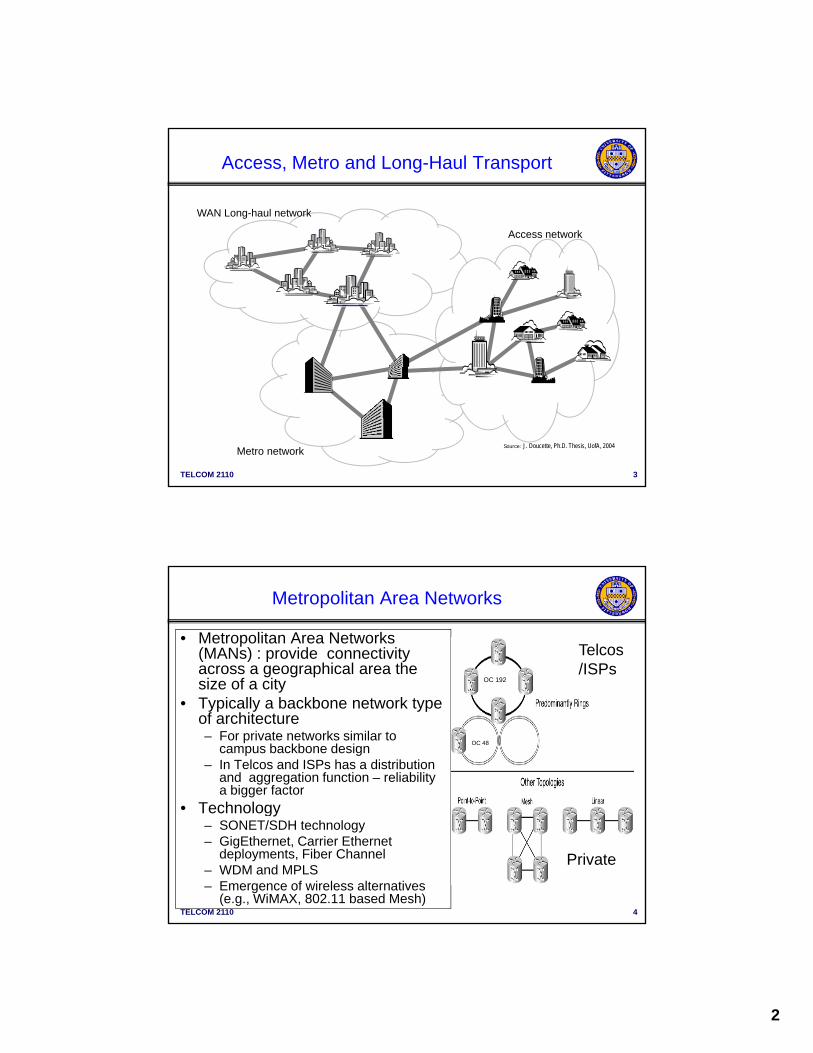
Access, Metro and Long-Haul Transport
WAN Long-haul network
Access network
TELCOM 2110 3
Metro networkSource: J. Doucette, Ph.D. Thesis, UofA, 2004
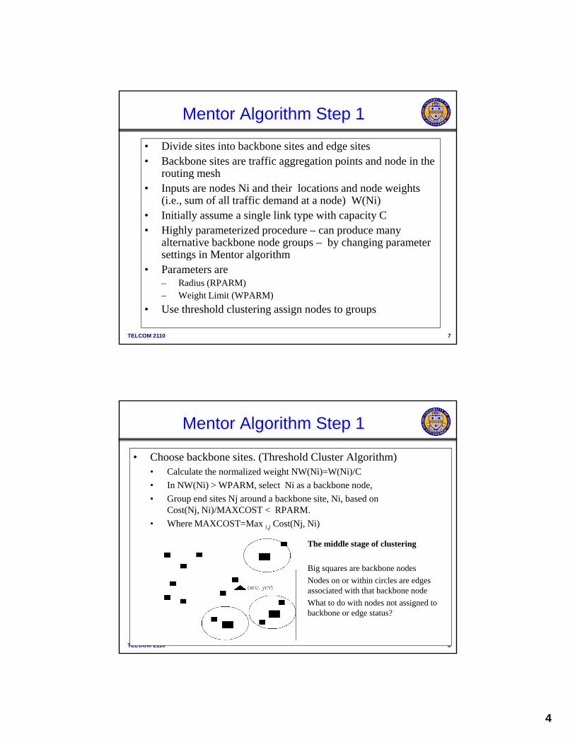
• Metropolitan Area Networks (MANs) : provide connectivity across a geographical area the size of a city
Metropolitan Area Networks
Telcos/ISPs
OC 192size of a city • Typically a backbone network type
of architecture– For private networks similar to
campus backbone design– In Telcos and ISPs has a distribution
and aggregation function – reliability a bigger factor
Technolog
OC 48
TELCOM 2110 4
• Technology– SONET/SDH technology– GigEthernet, Carrier Ethernet
deployments, Fiber Channel– WDM and MPLS– Emergence of wireless alternatives
(e.g., WiMAX, 802.11 based Mesh)
Private

3
• Cost and Reliability are a bigger factor than access network
• Typically seek to minimize cost • Subject to Constraints for example
Basic MAN Backbone Network Design
• Subject to Constraints … for example– Average Packet Delay must be < maximum– Reliability requirements– Throughput, etc.
• Approaches are a bit different for private/campus network and service provider
• Many algorithms in the literature
TELCOM 2110 5
Many algorithms in the literature – Graph theory based (e.g., MENTOR,
MENTOUR)– Optimization based, (e.g., SONET Toolkit
from Telcordia - used by many LECs to plan MANs)
– Heuristics – routing based (will see some with WANs)
Mentor (MEsh Network Topological Optimization and Routing) Algorithm Builds backbone and access network together – good for
Mesh Network Design Algorithms
Builds backbone and access network together good for campus type design
1. Backbone selection (classify backbone/edge sites) Threshold clustering
2. Creation of the initial topology Prim-Dijkstra tree or Backbone tour
3. Link addition
TELCOM 2110 6
Utilization based
4. Access topology Star , Esau-William, MSLA, etc.
Low complexity – reasonable quality – in some design tools
4
• Divide sites into backbone sites and edge sites • Backbone sites are traffic aggregation points and node in the
routing mesh
Mentor Algorithm Step 1
routing mesh• Inputs are nodes Ni and their locations and node weights
(i.e., sum of all traffic demand at a node) W(Ni)• Initially assume a single link type with capacity C• Highly parameterized procedure – can produce many
alternative backbone node groups – by changing parameter settings in Mentor algorithm
TELCOM 2110 7
g g• Parameters are
– Radius (RPARM)– Weight Limit (WPARM)
• Use threshold clustering assign nodes to groups
• Choose backbone sites. (Threshold Cluster Algorithm)• Calculate the normalized weight NW(Ni)=W(Ni)/C
• In NW(Ni) > WPARM select Ni as a backbone node
Mentor Algorithm Step 1
• In NW(Ni) > WPARM, select Ni as a backbone node,
• Group end sites Nj around a backbone site, Ni, based onCost(Nj, Ni)/MAXCOST < RPARM.
• Where MAXCOST=Max i,j Cost(Nj, Ni)
The middle stage of clustering
Big squares are backbone nodes
TELCOM 2110 8
Big squares are backbone nodes
Nodes on or within circles are edges associated with that backbone node
What to do with nodes not assigned to backbone or edge status?
5
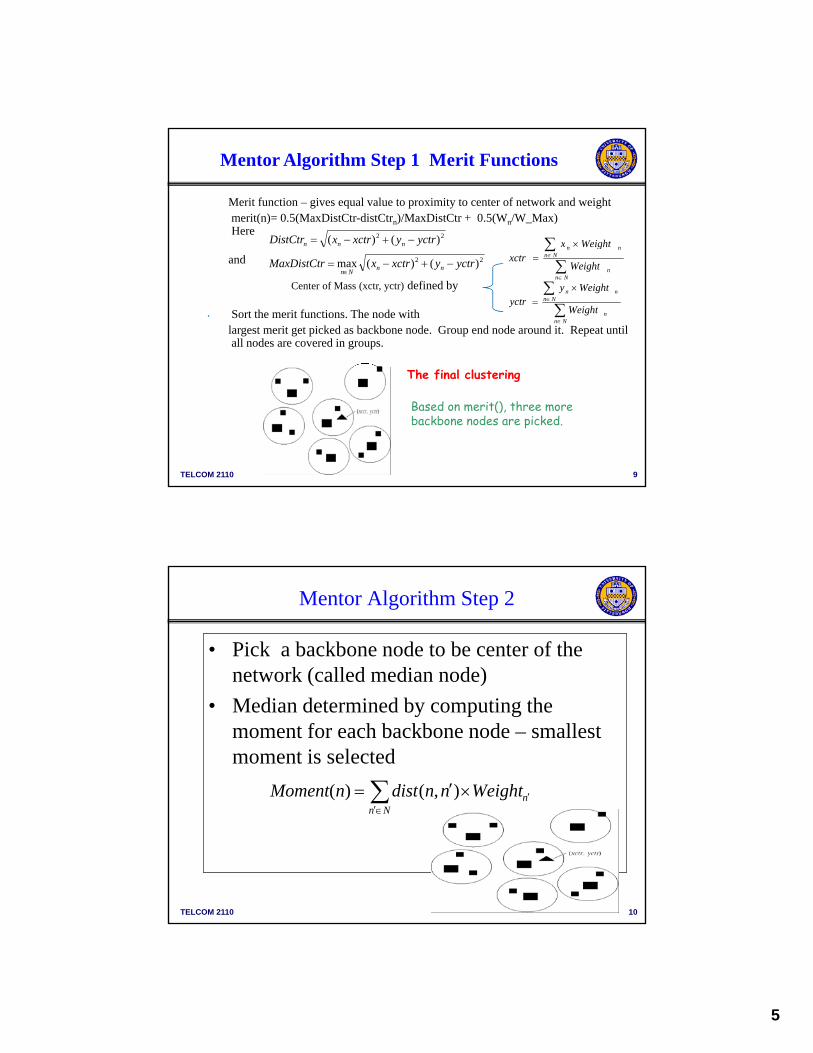
Merit function – gives equal value to proximity to center of network and weight merit(n)= 0.5(MaxDistCtr-distCtrn)/MaxDistCtr + 0.5(Wn/W_Max)Here 22 )()( yctryxctrxDistCtr nnn nn Weightx
Mentor Algorithm Step 1 Merit Functions
and
Center of Mass (xctr, yctr) defined by
• Sort the merit functions. The node with largest merit get picked as backbone node. Group end node around it. Repeat until all nodes are covered in groups.
22 )()(max yctryxctrxMaxDistCtr nnNn
Nnn
Nnnn
Weight
gxctr
Nnn
Nnnn
Weight
Weightyyctr
TELCOM 2110 9
Based on merit(), three more backbone nodes are picked.
The final clustering
Mentor Algorithm Step 2
• Pick a backbone node to be center of the network (called median node)( )
• Median determined by computing the moment for each backbone node – smallest moment is selected
nWeightnndistnMoment ),()(
TELCOM 2110 10
Nn
6
• Build a tree rooted at median connecting all nodes – Try to restrict interior tree nodes to backbone nodes
• Tree can be build using MST or SPT but Prim-Dijkstra is
Mentor Algorithm Step 3
• Tree can be build using MST or SPT , but Prim-Dijkstra is often recommended, recall link cost in Prim-Dijkstra:
)),(),((min nodeneighbordistneighborrootdistneighbors 10
TELCOM 2110 11
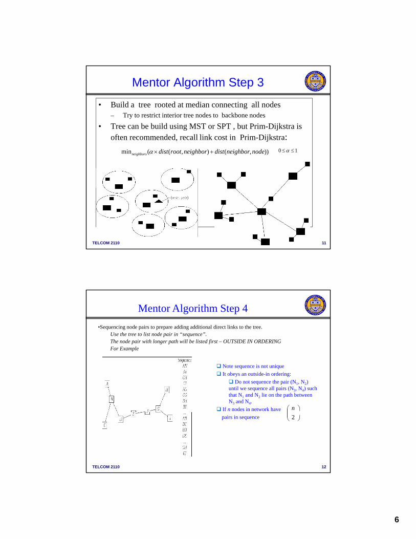
•Sequencing node pairs to prepare adding additional direct links to the tree. Use the tree to list node pair in “sequence”.The node pair with longer path will be listed first – OUTSIDE IN ORDERING For Example
Mentor Algorithm Step 4
p
Note sequence is not unique
It obeys an outside-in ordering:
Do not sequence the pair (N1, N2) until we sequence all pairs (N3, N4) such that N1 and N2 lie on the path between N3 and N4.
If n nodes in network have
n
TELCOM 2110 12
pairs in sequence
2

7
• For each nonadjacent node pair in the tree (Ni,Nj), select a home node H
• In (Ni,Nj) are two hops apart, home node is node between them
Mentor Algorithm Step 5 Homing
• If more than two hops apart, there are multiple candidates for home node H. For example consider (N1,N2) separated by N3 and N4.
• Where N3 is first node in path from N1 to N2 and N4 is the first node in path from N2 to N1if Cost(N1, N3) + Cost(N3,N2) <= Cost(N1, N4) + Cost(N4,N3) then
N3 is the home otherwise N4
TELCOM 2110 13
N3 is the home otherwise N4
•In general pick H that gives minimum costCost(Ni, H) + Cost(H,Nj) <= Cost(Ni, Nx) + Cost(Nx,Nj).
- H and Nx are intermediate nodes along the path.
• Decide which node pairs deserve direct links.• Start with the top node pair (N1,N2) in the sequence.
C l l t th b f b i li k d d
Mentor Algorithm Step 6
• Calculate the number of basic links needed
n=ceil(Traf(N1,N2)/C).• Compute resulting link utlization u=Traf(N1,N2)/(n*C)
• If u > utilmin, add direct link between N1 and N2.
• If u < utilmin, do not add direct link, but instead direct traffic 1 hop through the tree,
TELCOM 2110 14
• Add Traf(N1,N2) to Traf(N1,H) and Traf(H,N2). Here H is the home of (N1,N2).
• Remove (N1,N2) from the sequence and repeat Step 6 again until all node pairs are processed.
• Idea is to aggregate traffic to justify links connecting sites several hops apart in tree
8
• The three basic steps: backbone selection, tree building, and direct link addition are all O(n2) where n is the number of nodes.
Complexity of Mentor Algorithm
• It can be executed pretty fast.• Typically we will generate a set of designs based on the
same threshold parameter WPARM, RPARM,– Use vary in the restricted Prim-Dijkstra tree and/or vary utilmin . Prim-Dijkstra tree is parameterized by
)),(),((min nodeneighbordistneighborrootdisti hb 10
TELCOM 2110 15
The smaller the value of utilmin, the easier it is to add direct links.
• We then pick the best design from the set
)),(),((min nodeneighbordistneighborrootdistneighbors
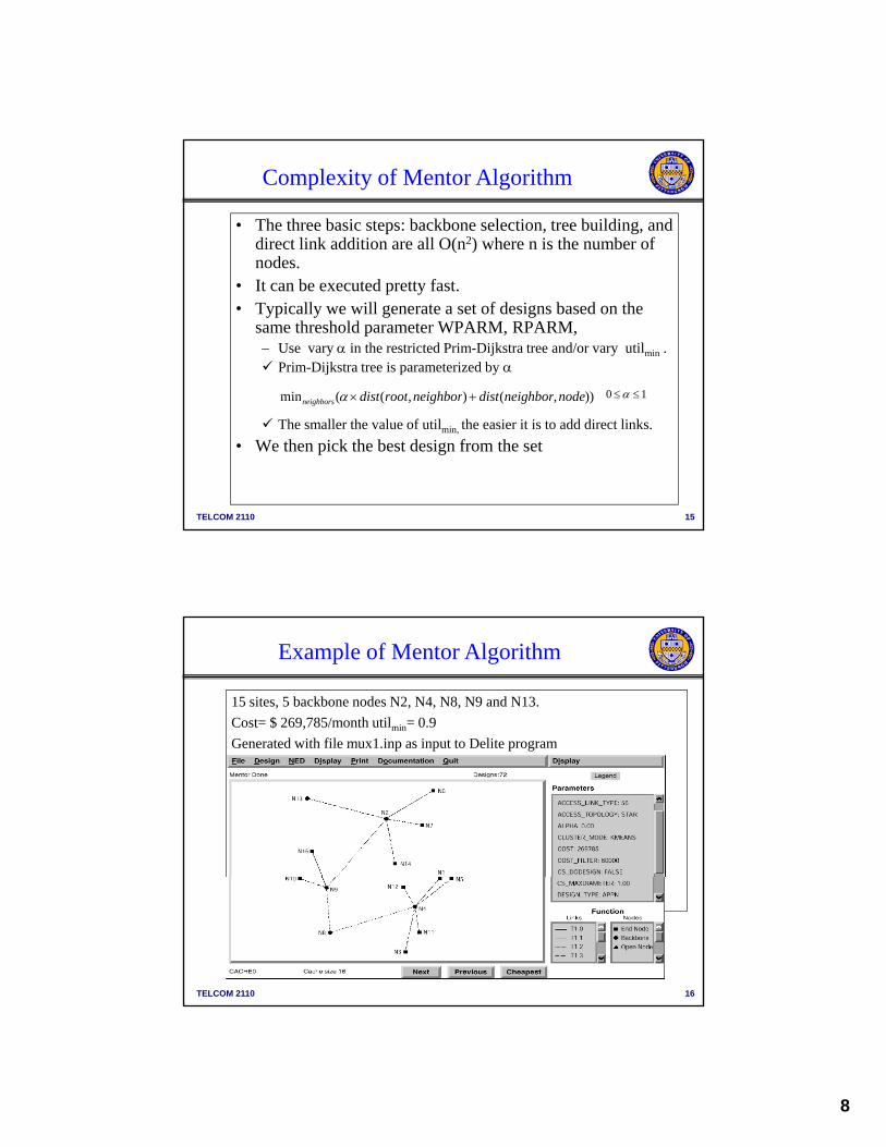
15 sites, 5 backbone nodes N2, N4, N8, N9 and N13.
Cost= $ 269,785/month utilmin= 0.9
Generated with file mux1 inp as input to Delite program
Example of Mentor Algorithm
Generated with file mux1.inp as input to Delite program
TELCOM 2110 16
9
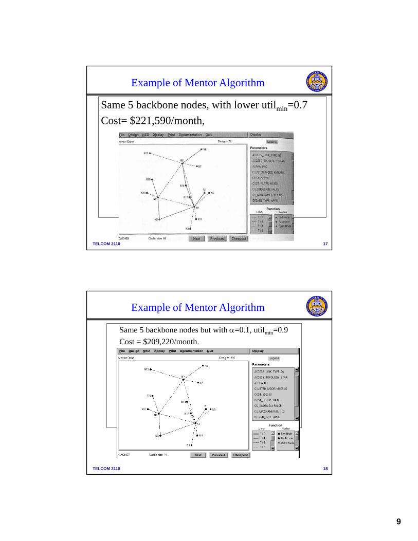
Same 5 backbone nodes, with lower utilmin=0.7
Cost= $221,590/month,
Example of Mentor Algorithm
TELCOM 2110 17
Same 5 backbone nodes but with =0.1, utilmin=0.9
Cost = $209,220/month.
Example of Mentor Algorithm
TELCOM 2110 18
10
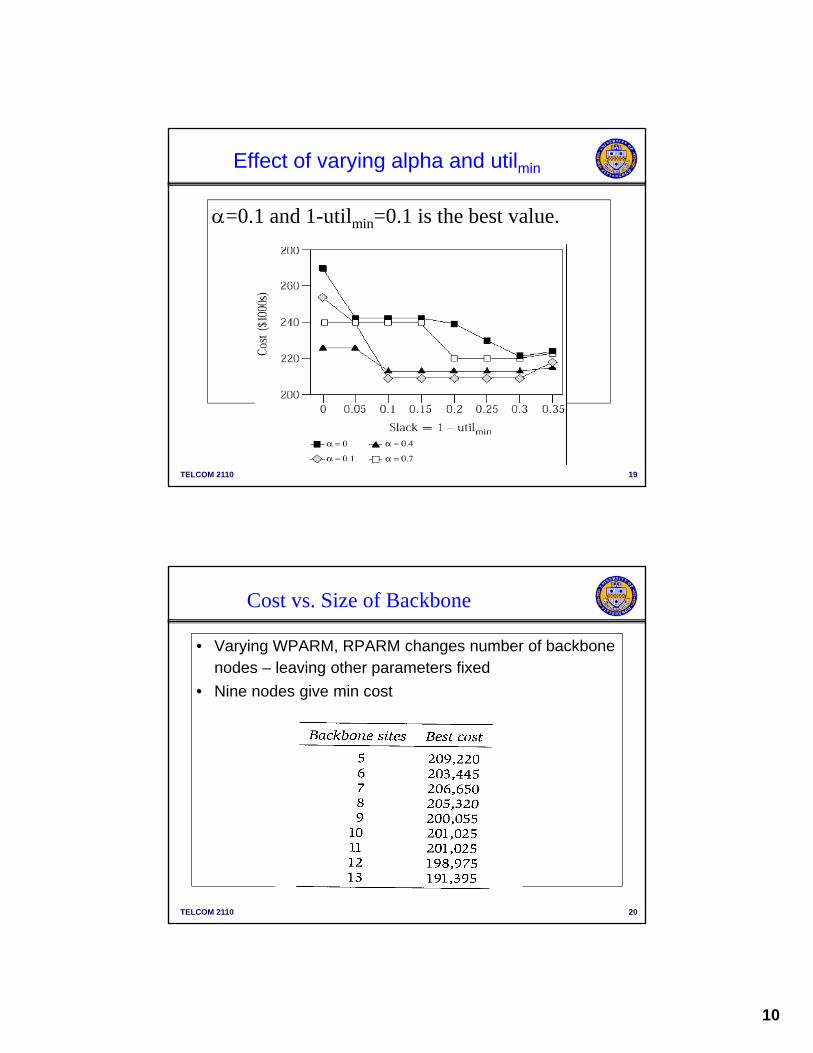
=0.1 and 1-utilmin=0.1 is the best value.
Effect of varying alpha and utilmin
TELCOM 2110 19
Cost vs. Size of Backbone
• Varying WPARM, RPARM changes number of backbone nodes – leaving other parameters fixed
Ni d i i• Nine nodes give min cost
TELCOM 2110 20

11
Reliability Issues
Given a network of nodes and links, one measure of reliability of the network is the probability that the working nodes are connectedconnected.
So far the cost-optimized networks that we have studied are often tree like. Tree designs have low reliability in many cases.
One measure of reliability is the connectedness of the network – a network is K –connected if it can loose K links and a path still exist between every source-destination pair.
Many real backbone networks are 2 or more connected
TELCOM 2110 21
y• If using MENTOR algorithm, one can simply change the
parameters WPRAM, RPARM, , utilmin to make the network more dense (at a greater cost )
• Alternative is MENTour algorithm
Remember steps in Mentor Algorithm 1. Backbone selection (classify backbone/edge sites)
Threshold clustering
MENTour
Threshold clustering
2. Creation of the initial topology Prim-Dijkstra tree
3. Link addition Utilization Based
4. Access topology Star , Esau-William, MSLA, etc.
TELCOM 2110 22
MENTour modifies Step 2 replacing tree rooted at median node with a Ring (tour) using nearest neighbor algorithm As in MENTOR should generate many designs by varying parameter
settings
12
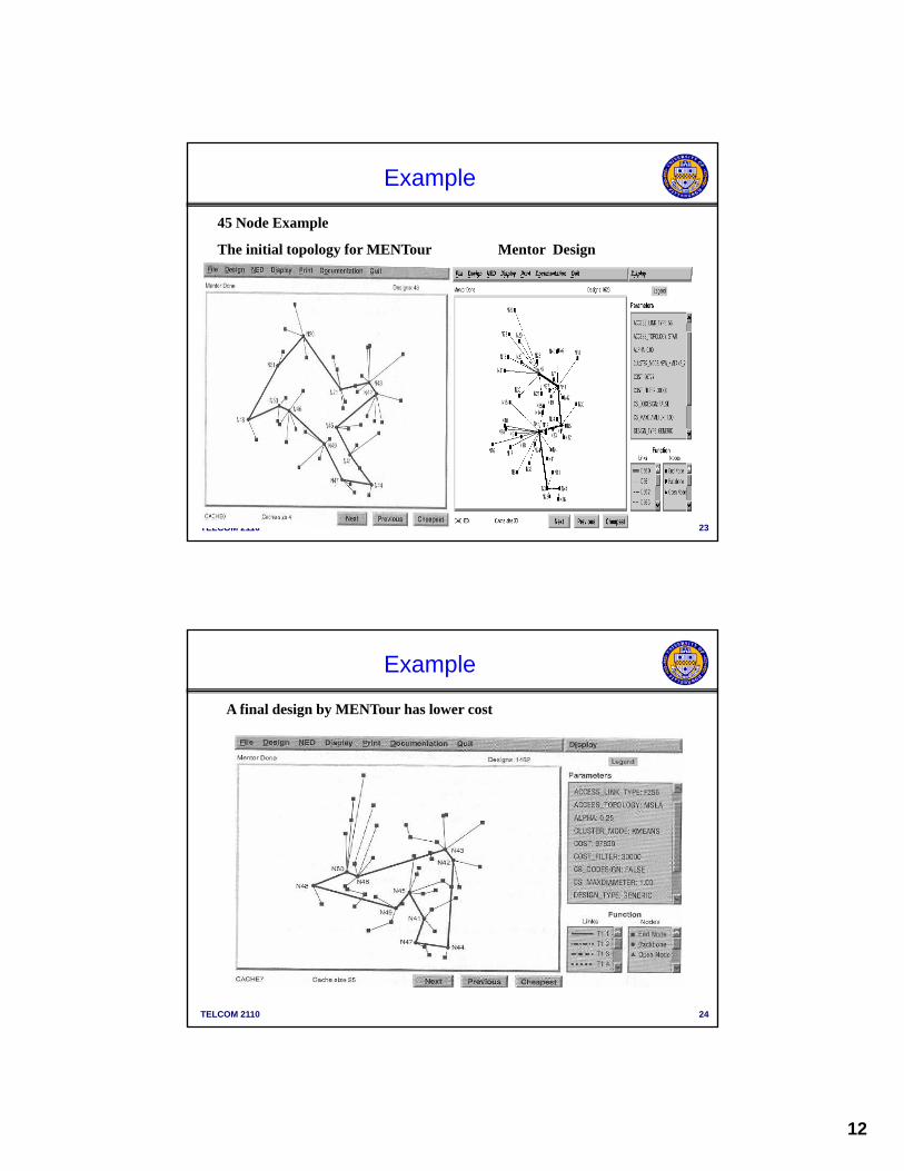
45 Node Example
The initial topology for MENTour Mentor Design
Example
TELCOM 2110 23
A final design by MENTour has lower cost
Example
TELCOM 2110 24

13
MAN Design
• Majority of MANs in use by Telcos and ISPs are based on rings in order to provide fault tolerance
• SONET/SDH is currently the bulk of implementationsSONET/SDH is currently the bulk of implementations• Can implement rings in other technology though (GigE),
wireless, etc.
TELCOM 2110 25
MAN Design
• MANs for Telcos typically have a distribution/collector structure with increasing channel rate as approach long haul networkhaul network
TELCOM 2110 26

14
Typical LEC Network Topology
HUB
Core Network
Collector Ring
HUBCO
CO CO
Metro Network
COHUBCO
HUBCO
OBusiness
Inter-Office Facilities
CO
VIP VIP
ISPISPCO = Central OfficeDLC = Digital Loop CarrierDSLAM = DSL Access MultiplexerISP = Internet Service ProviderONU = Optical Network Unit
TELCOM 2110 27
NU
xDSL
xDSL
LAN
IP, GbE
BusinessAccessRing
Access
DSLAM
DLCDLC
POS
ONT ONT•••PON
ADM
ONT = Optical Network TerminationPOS = Passive Optical SplitterPON = Passive Optical NetworkVIP = Video Information Provider
Synchronous Optical Network (SONET)
• The ANSI standard for synchronous data transmission on optical media.
• Provide end-to-end circuit-switched connectionsProvide end to end circuit switched connections• Provide efficient mechanism for multiplexing low-
speed connections into higher-speed connections– Define a base rate of 51.84 Mbps and a set of multiples
of the base rate known as "Optical Carrier levels (OCx)"
• Provide efficient way to extract low-speed streams from a high-speed stream at intermediate nodes
TELCOM 2110 28
• High availability (99.99% to 99.999%)– Rings have rapid service restoration in the
event of failures
15
The image cannot be displayed. Your computer may not have enough memory to open the image, or the image may have been corrupted. Restart your computer, and then open the file again. If the red x still appears, you may have to delete the image and then insert it again.
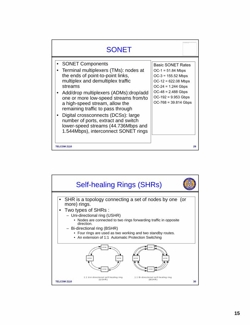
SONET
Basic SONET RatesOC-1 = 51.84 MbpsOC-3 = 155 52 Mbps
• SONET Components• Terminal multiplexers (TMs): nodes at
the ends of point-to-point links OC 3 155.52 MbpsOC-12 = 622.08 MbpsOC-24 = 1.244 GbpsOC-48 = 2.488 GbpsOC-192 = 9.953 GbpsOC-768 = 39.814 Gbps
the ends of point to point links, multiplex and demultiplex traffic streams
• Add/drop multiplexers (ADMs):drop/add one or more low-speed streams from/to a high-speed stream, allow the remaining traffic to pass throughDi it l t (DCS ) l
TELCOM 2110 29
• Digital crossconnects (DCSs): large number of ports, extract and switch lower-speed streams (44.736Mbps and 1.544Mbps), interconnect SONET rings
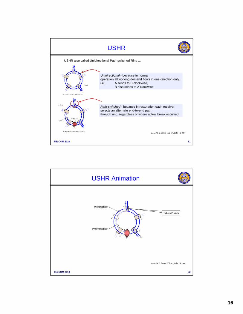
Self-healing Rings (SHRs)
• SHR is a topology connecting a set of nodes by one (or more) rings.
• Two types of SHRs :Two types of SHRs :– Uni-directional ring (USHR)
• Nodes are connected to two rings forwarding traffic in opposite direction.
– Bi-directional ring (BSHR)• Four rings are used as two working and two standby routes. • An extension of 1:1 Automatic Protection Switching
A D MA D M
TELCOM 2110 30
1 :1 B i-d ire c t io n a l s e lf-h e a lin g r in g(B S H R )
A D M A D M
A D M
1 :1 U n i-d ire c t io n a l s e lf -h e a lin g r in g(U S H R )
A D M A D M
A D M
16
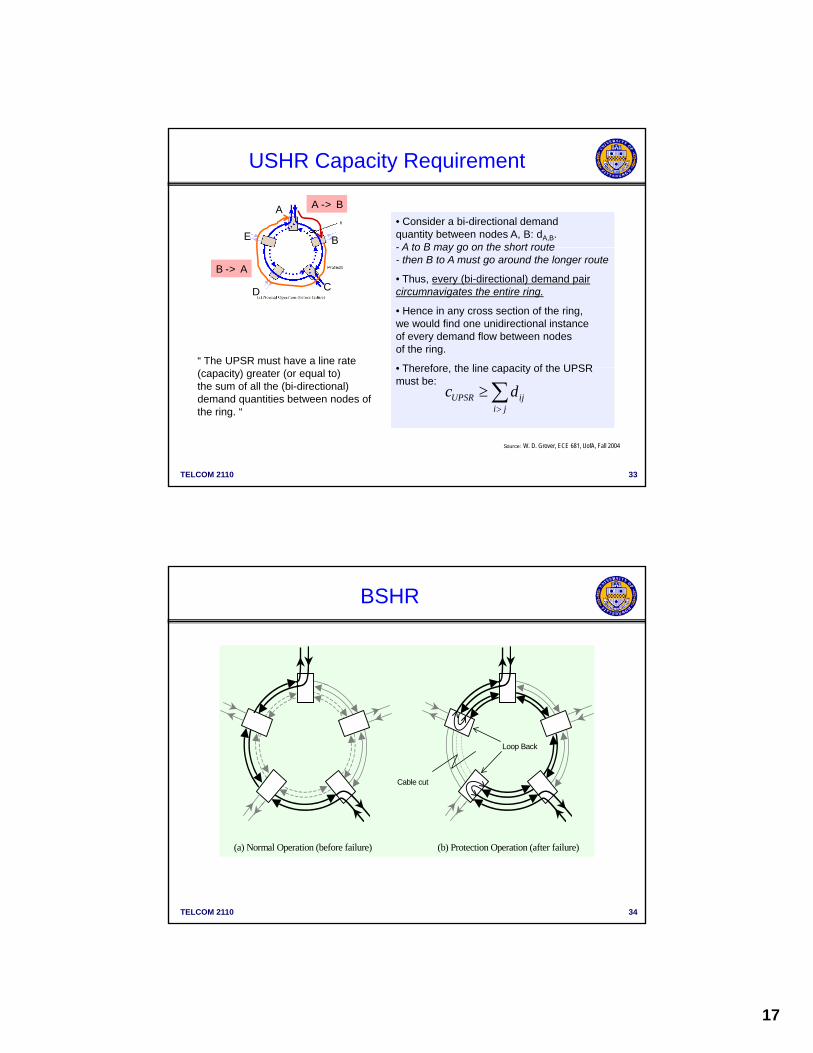
USHR also called Unidirectional Path-switched Ring ...
USHR
Unidirectional - because in normal operation all working demand flows in one direction only. i.e., A sends to B clockwise,
B also sends to A clockwise
Path-switched - because in restoration each receiver l t lt t d t d th
TELCOM 2110 31
selects an alternate end-to-end paththrough ring, regardless of where actual break occurred.
Source: W. D. Grover, ECE 681, UofA, Fall 2004
USHR Animation
Protection fibre
Working fibre 1
2
3
4
5
Tail-end Switch
TELCOM 2110 32
Source: W. D. Grover, ECE 681, UofA, Fall 2004
17
• Consider a bi-directional demand quantity between nodes A, B: dA,B.- A to B may go on the short route
A
E B
A -> B
USHR Capacity Requirement
- A to B may go on the short route- then B to A must go around the longer route
• Thus, every (bi-directional) demand paircircumnavigates the entire ring.
• Hence in any cross section of the ring,we would find one unidirectional instanceof every demand flow between nodes of the ring.
• Therefore the line capacity of the UPSR
D C
B -> A
“ The UPSR must have a line rate
TELCOM 2110 33
• Therefore, the line capacity of the UPSRmust be:
UPSR iji j
c d
(capacity) greater (or equal to)the sum of all the (bi-directional)demand quantities between nodes of the ring. “
Source: W. D. Grover, ECE 681, UofA, Fall 2004
BSHR
Cable cut
Loop Back
TELCOM 2110 34
(a) Normal Operation (before failure) (b) Protection Operation (after failure)

18
Bi-directional - because in normal operation working demand flows travel in opposite directions over the same
BSHR
(a) Normal Operation (before failure) (b) Protection Operation (after failure)
Cable cut
Loop Back
opposite directions over the sameroute through the ring
Also called Bi-directional Line-switched Ring (BLSR)
Line-switched - because in restoration the compositeoptical line transmission signal is switched to the other direction around the ring (on the other fibre pair)“ The BLSR must have a line rate
TELCOM 2110 35
g ( p )specifically around the failed section.
Note implication: Protection fibre capacity must equal the largest-working capacitycross-section of any span on the ring.
The BLSR must have a line rate (capacity) greater (or equal to)the largest sum of demands routedover any one span of the ring. “
BSHR
Protection fibres
Working fibres
Loop-back
1
2
34
5
TELCOM 2110 36
Loop-back
Source: W. D. Grover, ECE 681, UofA, Fall 2004
19
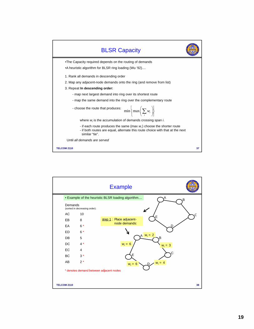
•The Capacity required depends on the routing of demands
•A heuristic algorithm for BLSR ring loading (Wu ‘92)....
1. Rank all demands in descending order
BLSR Capacity
1. Rank all demands in descending order
2. Map any adjacent-node demands onto the ring (and remove from list)
3. Repeat In descending order:
- map next largest demand into ring over its shortest route
- map the same demand into the ring over the complementary route
- choose the route that produces:min max i
i
w
TELCOM 2110 37
where wi is the accumulation of demands crossing span i.
- if each route produces the same {max wi } choose the shorter route- if both routes are equal, alternate this route choice with that at the next
similar “tie”.
Until all demands are served
i
• Example of the heuristic BLSR loading algorithm....
Demands(sorted in decreasing order):
AC 10
AB
C
Example
AC 10
EB 8
EA 6 *
ED 6 *
DB 5
DC 4 *
EC 4
AB
step 1 : Place adjacent-node demands:
wi = 6 wi = 3
wi = 2
D
CE
TELCOM 2110 38
BC 3 *
AB 2 * D
CE
* denotes demand between adjacent nodes
wi = 6 wi = 4

20
Remaining demands(sorted):
AC 10
EB 8
AB
step 2 : Consider routing of the AC demand:
6
wi = 2+ 10 = 12
Example
min max iw
EB 8
DB 5
EC 4
D
CE
wi = 6
wi = 6 wi = 4
wi = 13
AB
wi = 16 wi = 3
wi = 2
i
TELCOM 2110 39
D
CE
wi = 16 wi = 14 shorter route is preferred:
map AC via route A-B-C (max wi = 13)
Remaining demands(sorted):
EB 8
AB
step 3 : Consider routing of the EB demand:
14
wi = 20
Example
EB 8
DB 5
EC 4
D
CE
wi = 14
wi = 6 wi = 4
wi = 13
AB
wi = 6 wi = 21
wi = 12
TELCOM 2110 40
D
CE
wi = 14 wi = 12 shorter route is again preferred:
map EB via route E-A-B
(max wi = 20)
21
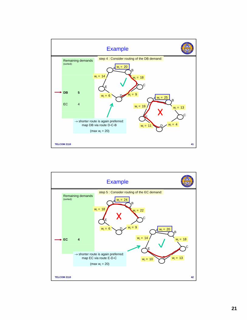
Remaining demands(sorted):
AB
step 4 : Consider routing of the DB demand:
14
wi = 20
Example
DB 5
EC 4
D
CE
wi = 14
wi = 6 wi = 9
wi = 18
AB
wi = 19 wi = 13
wi = 25
TELCOM 2110 41
shorter route is again preferred: map DB via route D-C-B
(max wi = 20)
D
CE
wi = 11 wi = 4
Remaining demands(sorted):
AB
step 5 : Consider routing of the EC demand:
18
wi = 24
Example
EC 4
D
CE
wi = 18
wi = 6 wi = 9
wi = 22
AB
wi = 14 wi = 18
wi = 20
TELCOM 2110 42
shorter route is again preferred: map EC via route E-D-C
(max wi = 20)
D
CE
wi = 10 wi = 13
22
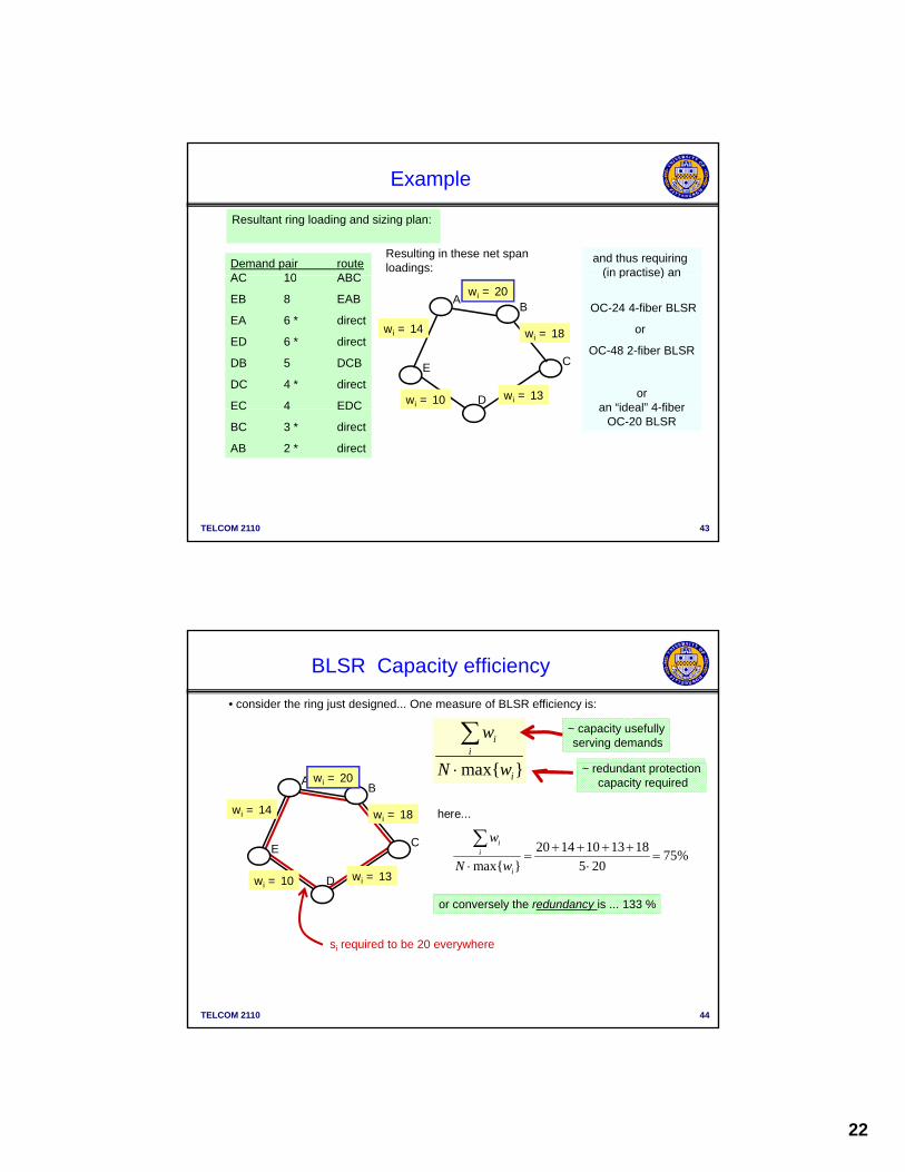
Resultant ring loading and sizing plan:
Demand pair routeAC 10 ABC
Resulting in these net span loadings:
and thus requiring (in practise) an
Example
D
AB
CE
wi = 14
wi = 10 wi = 13
wi = 18
wi = 20AC 10 ABC
EB 8 EAB
EA 6 * direct
ED 6 * direct
DB 5 DCB
DC 4 * direct
EC 4 EDC
(in practise) an
OC-24 4-fiber BLSR
or
OC-48 2-fiber BLSR
oran “ideal” 4-fiber
TELCOM 2110 43
EC 4 EDC
BC 3 * direct
AB 2 * direct
an ideal 4 fiberOC-20 BLSR
• consider the ring just designed... One measure of BLSR efficiency is:
ii
w ~ capacity usefullyserving demands
BLSR Capacity efficiency
D
AB
CE
wi = 14
wi = 10 wi = 13
wi = 18
wi = 20 max{ }iN w ~ redundant protectioncapacity required
20 14 10 13 1875%
max{ } 5 20
ii
i
w
N w
here...
TELCOM 2110 44
or conversely the redundancy is ... 133 %
si required to be 20 everywhere
23
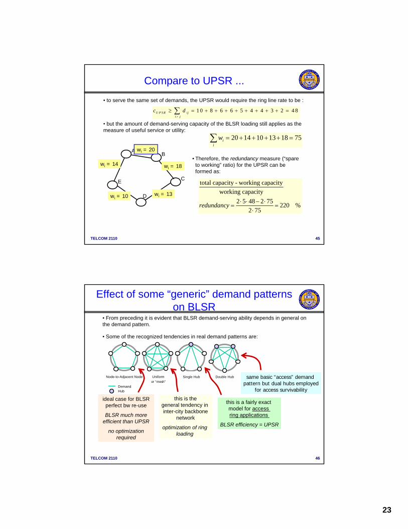
• to serve the same set of demands, the UPSR would require the ring line rate to be :
1 0 8 6 6 5 4 4 3 2 4 8U P S R iji j
c d
• but the amount of demand-serving capacity of the BLSR loading still applies as the
Compare to UPSR ...
AB
CE
wi = 14 wi = 18
wi = 20
but the amount of demand-serving capacity of the BLSR loading still applies as the measure of useful service or utility:
20 14 10 13 18 75ii
w
• Therefore, the redundancy measure (“spare to working” ratio) for the UPSR can be formed as:
total capacity - working capacity
TELCOM 2110 45
Dwi = 10 wi = 13
total capacity working capacity
working capacity
2 5 48 2 75220 %
2 75redundancy
• From preceding it is evident that BLSR demand-serving ability depends in general on the demand pattern.
• Some of the recognized tendencies in real demand patterns are:
Effect of some “generic” demand patterns on BLSR
HubDemand
Node-to-Adjacent Node Double HubSingle HubUniform
or “mesh”
ideal case for BLSRf t b
this is thegeneral tendency in this is a fairly exact
same basic “access” demand pattern but dual hubs employed
for access survivability
TELCOM 2110 46
perfect bw re-use
BLSR much moreefficient than UPSR
no optimization required
general tendency in inter-city backbone
network
optimization of ring loading
ymodel for access ring applications
BLSR efficiency = UPSR

24
SHRs Restoration Capability
• USHR– 100% restoration for a single link failure but no g
protection against a node failure.
• BSHR– 100% restoration for a single link or ADM failure.
– Fully automatic for a fast restoration.
– Spare capacity of each link can be shared between
TELCOM 2110 47
p p ytwo working paths.
– More expensive but usually less than twice as expensive
• SONET rings operate at OC-n line rates and the STS-1 tributaries are the “channels”
• The nodes of a ring are equipment called “Add-Drop Multiplexers” (ADMs)
• SONET rings typically have a maximum of 16 active nodes, plus “glass-through” sites
Rings
SONET rings typically have a maximum of 16 active nodes, plus glass through sites
• “Glass-throughs” are just nodes transited by the ring, but where no ADM is present
• “Glass-throughs” may be simply fiber splices or a regenerator point (“pass throughs”)
• Demand splitting refers to whether or not the total demand exchanged between two nodes has to be kept together on the same route of a ring or can be ‘split’
• Time slot interchange (TSI) refers to whether the ADMs have the ability to cross-connect timeslot contents (assign a new time slot to a demand on the next span)
• More recent Optical rings have a DWDM optical line signal and add / drop single
TELCOM 2110 48
p g p g p gwavelengths or wave-bands
- the logical “channel” is a wavelength () or waveband- UPSR < - > OPPR (Optical Path Protection Ring)- BLSR < - > OSPR (Optical Shared Protection Ring)- ADM < - > OADM- TSI (Time slot interchange) < - > conversion
25
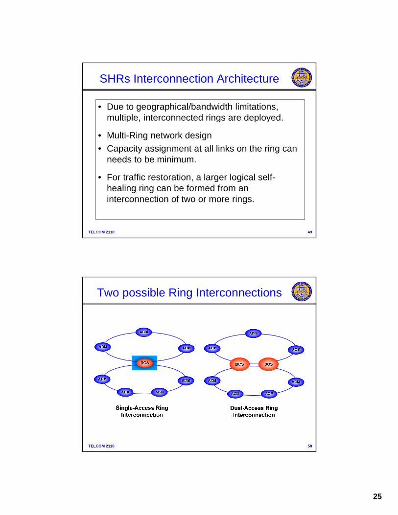
SHRs Interconnection Architecture
• Due to geographical/bandwidth limitations, multiple, interconnected rings are deployed.p , g p y
• Multi-Ring network design
• Capacity assignment at all links on the ring can needs to be minimum.
• For traffic restoration, a larger logical self-
TELCOM 2110 49
For traffic restoration, a larger logical selfhealing ring can be formed from an interconnection of two or more rings.
Two possible Ring Interconnections
TELCOM 2110 50
26
C
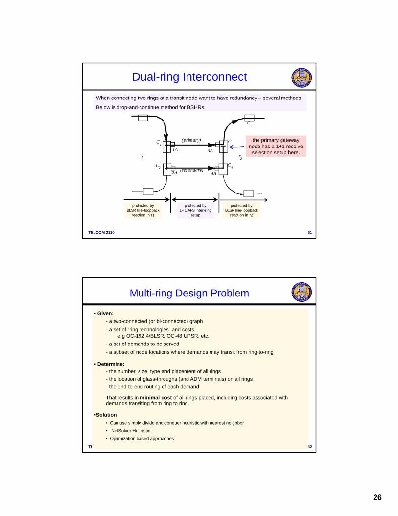
Dual-ring Interconnect
When connecting two rings at a transit node want to have redundancy – several methods
Below is drop-and-continue method for BSHRs
1A
2A
3A
4A
(primary)
(secondary)
r1 r
2
C3
C4
C1
C2
C5
the primary gateway node has a 1+1 receive
selection setup here.
TELCOM 2110 51
protected byBLSR line-loopback
reaction in r1
protected byBLSR line-loopback
reaction in r2
protected by1+1 APS inter-ring
setup
• Given:
- a two-connected (or bi-connected) graph
- a set of “ring technologies” and costs. e g OC 192 4/BLSR OC 48 UPSR etc
Multi-ring Design Problem
e.g OC-192 4/BLSR, OC-48 UPSR, etc.
- a set of demands to be served.
- a subset of node locations where demands may transit from ring-to-ring
• Determine:
- the number, size, type and placement of all rings
- the location of glass-throughs (and ADM terminals) on all rings
- the end-to-end routing of each demand
TELCOM 2110 52
That results in minimal cost of all rings placed, including costs associated with demands transiting from ring to ring.
•Solution
• Can use simple divide and conquer heuristic with nearest neighbor
• NetSolver Heuristic
• Optimization based approaches

27
• Upper bound on number of ring candidates to consider:
logic: Every combination of 2, 3, 4....up to N nodes defines a prospective collectionof active ADM nodes that could be grouped together to define one ring.
On the complexity of multi-ring design
2
2 1N
N
i
NQ N
i
• Upper bound on the number of different multi-ring designs that exist:
logic: Now, every combination of 1, 2, 3, 4....up to some pre-determined maximumnumber of rings can be considered for feasibility and cost as a multi-ring design solution.
- in ideal case of rings with no capacity limit
TELCOM 2110 53
in ideal case of rings with no capacity limit,can show that more than N-1 rings not needed.
1
1
N
j
Q
j
and ... also multiply by the number of “ring technologies”
being considered.
60
7010
Question: How big is ?
10
20
30
40
50
60
No
. of
Po
ss
ible
De
sig
ns
10
10
10
10
10
10
TELCOM 2110 54
0
3 4 5 6 7 8 9 10 11 12 13 14 15 16
No. of Node s
10
illustration: a 10 node network: 1013 possible rings, 1021 possible multi-ring networks
(over 100 million years to evaluate all designs at 10 6 design evaluations / sec.) !

28
Concept
• graph coverage: ....a set of rings that covers every edge of the graph. This is one class of ring network.
in a BLSR how well are the w quantities “balanced” ? (since
Key concepts in multi-ring design
• Balance
• Capture
• Span elimination
• Dual-ring interconnect
....in a BLSR, how well are the wi quantities balanced ? (sincethe largest of them dictates the protection capacity).
....to what extent does a given ring tend to serve demands that both originate and terminate in the same ring.
....a multi-ring design may not “cover” all graph edges, if the working demands can take non-shortest path routes.
....for the highest service availability, some demands may employ geographically redundant duplicate inter-ring transfers
TELCOM 2110 55
• transit sites
•glass-throughs
geographically redundant duplicate inter ring transfers
....not all nodes may be sites where demands can switch rings.
....each ring needs ADMs where demands add / drop, but not elsewhere ( ~> Express rings etc.).
• a set of rings that uses or overlies all edges of the physical facilities graph is called a “ring cover”.
• “Coverage-based” design is a special (simpler) case of multi-ring design.
M ll th i i t t t ll d d t il t “ ll
Graph coverage
• More generally the aim is to protect all demands, not necessarily to “cover all spans.” “span eliminations”
TELCOM 2110 56
a three ring “cover”a single ring design
that may also serve alldemands…
Q. what is implied?
example
Source: W. D. Grover, ECE 681, UofA, Fall 2004
29
Net Solver (Gardner, et al., Globecom ‘95)
• Objective– Find min-cost ring design that serves all demands.
• Key Assumptions & Constraintsy p & C– Cost is calculated based on fixed and variable costs.
– Requires an initial ring design.
– Ring capacity is fixed and modular (rings not “ideal”).
• Methodology1. Route demands over the initial set of rings using either (1) shortest path, (2)
shortest ring transition, or (3) minimum congestion routing (user-defined).
2. Compute the total cost of the initial design.
TELCOM 2110 57
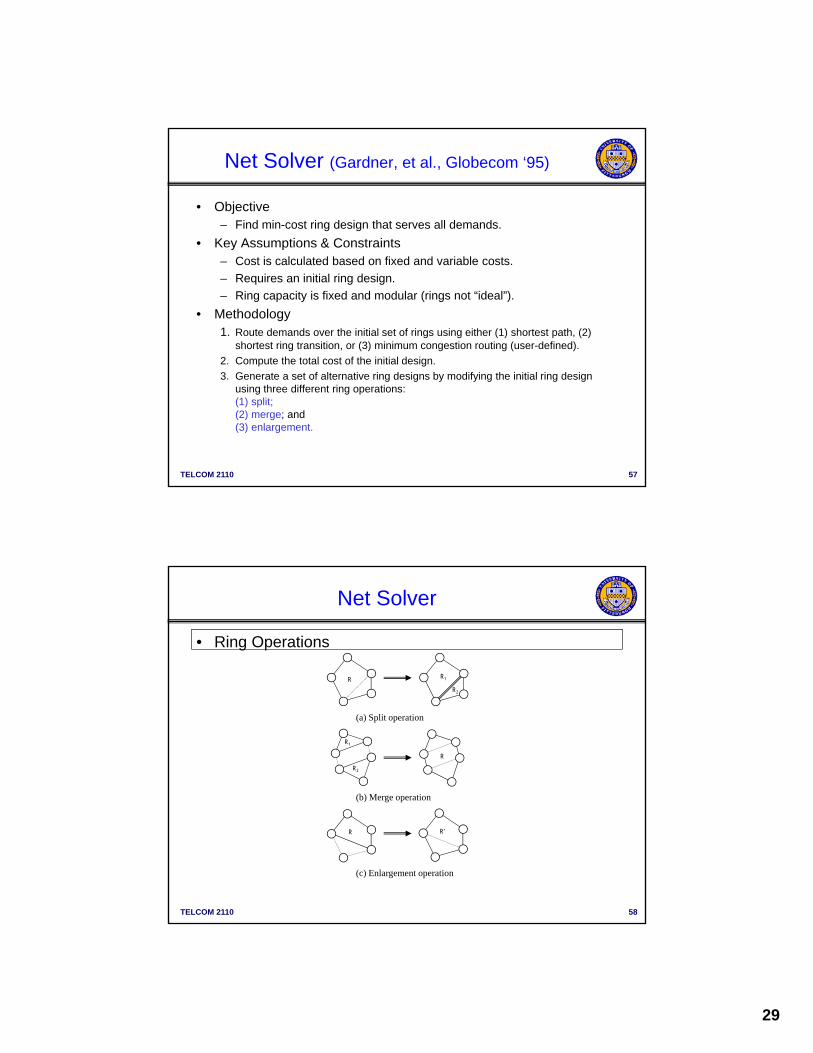
3. Generate a set of alternative ring designs by modifying the initial ring design using three different ring operations:(1) split; (2) merge; and (3) enlargement.
Net Solver
• Ring Operations
R R1
R2
R
R1
R2
(a) Split operation
(b) Merge operation
TELCOM 2110 58
R R’
(c) Enlargement operation
30
Net Solver (cont’d)
• Methodology (cont’d)4. Route demands and compute the total cost for each alternative
designdesign.
5. Select the design with the lowest total cost.
6. Repeat steps 3-5 until no further improvements in cost can be obtained.
• Capabilities– BLSR, UPSR and mixed designs.
TELCOM 2110 59
– Accounts for fixed ring capacities.
– Identifies the location of active/passive nodes and demand routing.
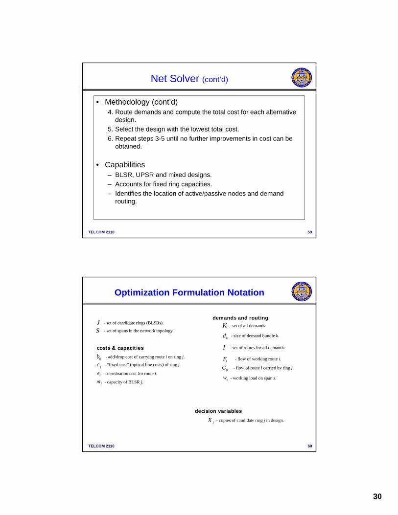
Optimization Formulation Notation
S - set of spans in the network topology.
J - set of candidate rings (BLSRs). K - set of all demands.
d size of demand bundle k
demands and routing
swjm - capacity of BLSR j.
- working load on span s.
jc - “fixed cost” (optical line costs) of ring j.
I - set of routes for all demands.
ijb - add/drop cost of carrying route i on ring j.
ie - termination cost for route i.
kd - size of demand bundle k.
iF - flow of working route i.
ijG - flow of route i carried by ring j.
costs & capacities
TELCOM 2110 60
jX - copies of candidate ring j in design.
decision variables
31
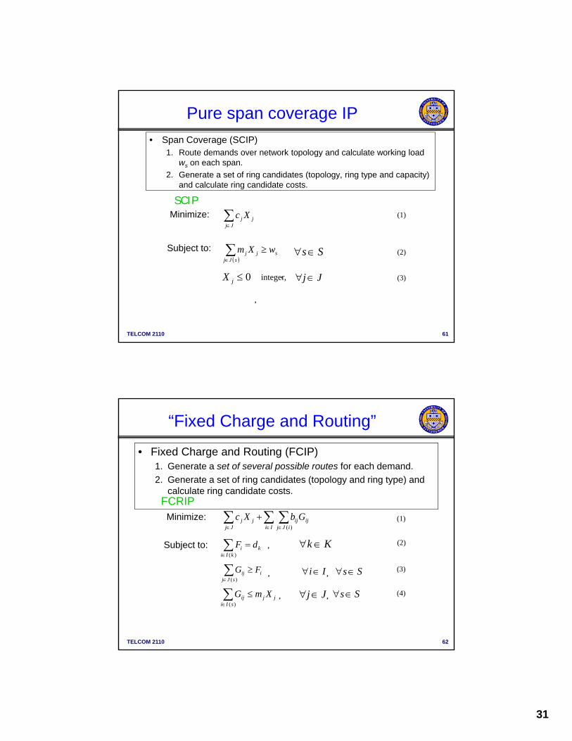
Pure span coverage IP
• Span Coverage (SCIP)1. Route demands over network topology and calculate working load
ws on each span.
2 Generate a set of ring candidates (topology ring type and capacity)2. Generate a set of ring candidates (topology, ring type and capacity) and calculate ring candidate costs.
SCIPMinimize:
Subject to:
Jjsjj wXm Ss (2)
(1)Jj
jj Xc
TELCOM 2110 61
,
,
sJj
0jX integer, Jj (3)
“Fixed Charge and Routing”
• Fixed Charge and Routing (FCIP) 1. Generate a set of several possible routes for each demand.
2. Generate a set of ring candidates (topology and ring type) and2. Generate a set of ring candidates (topology and ring type) and calculate ring candidate costs.
Minimize:
FCRIP
Subject to:
Ii iJj
ijijJj
jj GbXc)(
(1)
)(kIi
ki dF , Kk (2)
G ( )
TELCOM 2110 62
)(sJj
iij FG Ii Ss, ,(3)
)(sIi
jjij XmG , Jj Ss, (4)
32
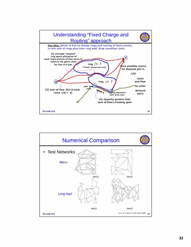
Understanding “Fixed Charge and Routing” approach
D
(3) amongst “stacked” ring spans allocation of
Key idea: Solver is free to choose rings and routing of flows jointly,to min cost of rings plus inter-ring add/ drop transition costs
O
D
ring
ring
j J
j J
three possible routes for demand pair k,
I(k)
route and flow
for otheradd/ drop
(“fixed” optical line cost)
each ring’s portion of flow sums to total on the given route
for that O-D pair
TELCOM 2110 63
(2) sum of flow F(i) to each route I(k) = dk
for other
demand pairs
(4) capacity greater thansum of flows crossing span
routing dependentadd/ drop costs
add/ dropcosts
Numerical Comparison
1
23
4
1415
0
2 3 4
5
9
10
11 1315 19
• Test Networks
1
1116
2122
26
27
28
29
30
5
6
7
8
9
10
11
1213
3
5
7
10
11
12
13
14
15
16
17
18
20
22 23
33
38
39
40
42
43
Net15 Net20
Metro
1
6
7
8
12
14
16
17
18
TELCOM 2110 64
2
34
56
7
8
9
10
12
13
14
15
17
18
192023
24
25
31
32
1
2
4
6
7
8
9
16 18
19
21
22 23
24
25
26
27
28
29
30
31
32
3435
36 37
41
Net32 Net43
Long-haul
Source: W. D. Grover, ECE 681, UofA, Fall 2004

33
Numerical Results
• Modeling Assumptions– Ring types: 12- OSPR and 48- OSPR.
Cost model: 4 times capacity for twice the cost– Cost model: 4 times capacity for twice the cost.
– No restrictions on inter-ring transition locations.
• Experimental Procedure1.Formulated each IP in AMPL mathematical
programming language.
2 Populated AMPL data sets
TELCOM 2110 65
2.Populated AMPL data sets.
3.Generated problem instances using AMPL and solved with CPLEX.
4.Entered solutions into SONET Planner (Nortel Networks) to obtain final detailed costing.
Results
Cost ($000s)
RingBuilder SCIP FCRIP
* - time limit exceeded, best feasible solution shown.
RingBuilder SCIP FCRIP
Net15 6,535 5,810 7,187*
Net20 9,886 10,083 8,953*
Net32 91,596 90,291 96,368*
Net45 116,674 130,100* -
RingBuilder SCIP FCRIP
TELCOM 2110 66
RingBuilder SCIP FCRIP
Net15 6.2 1.6 43,200
Net20 10.5 38.7 43200
Net32 8.5 361 43,200
Net45 1,233 43,200 -
43,200 sec = 12 hour run-time limit

34
MANs
• Discussed a few algorithms/approaches to MAN design– Graph theory based (e.g., MENTOR, MENTOUR)– Optimization based (focus largely on ring networks ) Op ( g y g )
• (e.g., SONET Toolkit from Telcordia – RingBuilder – TRLabs, etc.)
– Heuristics – routing based (will see some with WANs)
• MANs are evolving with newer technology– DWDM and multi-provisioning– Virtual Private LAN Service (VPLS) over service provider network
(GEthernet interconnect over MAN)– WiMAX for wireless last mile or MAN interconnect
TELCOM 2110 67
WiMAX for wireless last mile or MAN interconnect– SAN (Storage Area Networks)– Etc.
Top Related