


Languages
Pages
Legal


Measurements in Fluid Mechanics058:180:001 (ME:5180:0001)
Time & Location: 2:30P - 3:20P MWF 218 MLH
Office Hours: 4:00P – 5:00P MWF 223B-5 HL
Instructor: Lichuan [email protected]
http://lcgui.net

2
Lecture 5. Dynamic response of measuring systems

3
Models of dynamic response
Dynamic measuring system - at least one of inputs is time dependent
Description of dynamic response - differential equation that contains time derivatives.
- Linear dynamic response: linear differential equation
Simple dynamic response
- Non-linear dynamic response: non-linear differential equation
Zero-order systems
K – static sensitivity
- approximated by single, linear, ordinary differential equation with constant coefficients
x – input y – output t – time
constant coefficients: ai , i=1,2,,n ; bj , j=1,2,,m
- example of zero-order systems: electric resistor
- time independent
4
Models of dynamic response
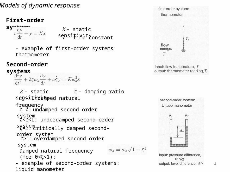
First-order systems
Second-order systems
K – static sensitivity
– time constant
- example of first-order systems: thermometer
K – static sensitivity – damping ratio n – undamped natural frequency
=0: undamped second-order system
=1: critically damped second-order system
0<<1: underdamped second-order system
>1: overdamped second-order system
Damped natural frequency (for 0<<1):
- example of second-order systems: liquid manometer
5
Type of input
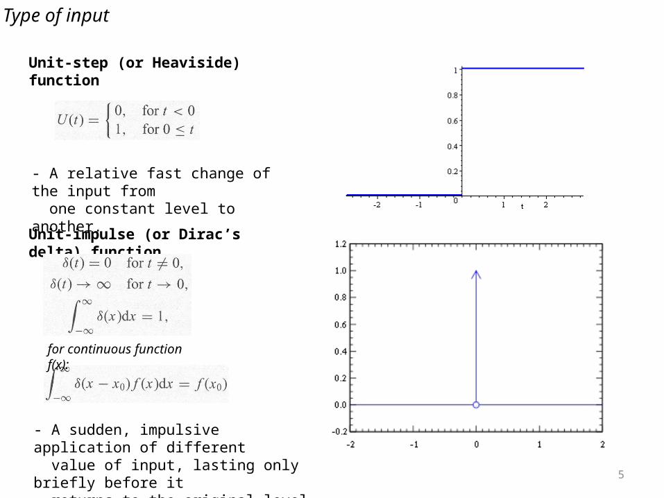
Unit-step (or Heaviside) function
Unit-impulse (or Dirac’s delta) function
- A relative fast change of the input from one constant level to another.
- A sudden, impulsive application of different value of input, lasting only briefly before it returns to the original level
for continuous function f(x):

6
Type of input
Unit-slope ramp function
Periodic function
- A gradual change of the input, starting from a constant level persisting monotonically.
- Function f(t) with period T so that f(t)=f(t+nT)
T
- Can be decomposed in Fourier series

7
Dynamic response of first-order system
Step response
𝑥 (𝑡 )=𝐴𝑈 (𝑡 )
𝜏𝑑𝑦𝑑𝑡
+𝑦=𝐾𝐴𝑈 (𝑡 )=𝐾𝐴 for t ≥ 0
𝑦 (𝑡 )𝐾𝐴
=1−𝑒−𝑡 /𝜏
∆ 𝑥 (𝑡 )𝐴
=1−𝑦 (𝑡 )𝐾𝐴
=𝑒−𝑡 /𝜏
t/ 1 2 3 4
x/A 37% 13.5% 5% 1.8%

8
Dynamic response of first-order system
Impulse response
𝑥 (𝑡 )=𝐴𝛿 (𝑡 ) , 𝜏𝑑𝑦𝑑𝑡
+𝑦=𝐾𝐴𝛿 (𝑡 ) , 𝑦 (𝑡 )𝐾𝐴
= 1𝜏𝑒−𝑡 /𝜏 ,
∆ 𝑥 (𝑡 )𝐴
=−1𝜏𝑒− 𝑡 /𝜏
t/ 1 2 3 4
-x/A 37% 13.5% 5% 1.8%
Ramp response
𝑥 (𝑡 )=𝐴𝑟 (𝑡 ) , 𝜏𝑑𝑦𝑑𝑡
+𝑦=𝐾𝐴𝑟 (𝑡 ) ,𝑦 (𝑡 )𝐾𝐴
=𝑒−𝑡 /𝜏+𝑡−𝜏 ,∆ 𝑥 (𝑡 )𝐴
=−𝜏 𝑒− 𝑡𝜏+𝜏
t/ 1 2 3 4
-(x/A-) 37% 13.5% 5% 1.8%
9
Dynamic response of first-order system
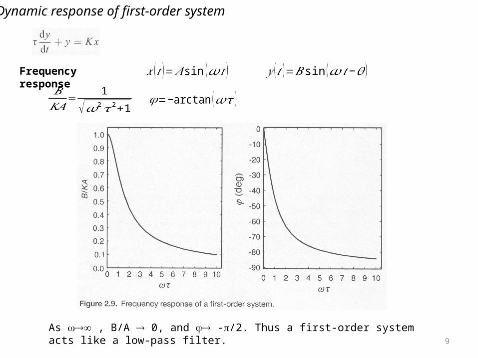
Frequency response 𝑥 (𝑡 )=𝐴 sin (𝜔𝑡 ) 𝑦 (𝑡 )=𝐵 sin (𝜔 𝑡−𝜃 )𝐵𝐾𝐴
=1
√𝜔2𝜏2+1𝜑=−arctan (𝜔𝜏 )
As , B/A 0, and -/2. Thus a first-order system acts like a low-pass filter.

10
Dynamic response of second-order system
Step response
- Damping ratio determines response
- Critically damped & overdamped system output increases monotonically towards static level
- output of underdamped system oscillates about the static level with diminishing amplitude.
- Lightly damped system (<<1) are subjected to large-amplitude oscillation that persist over a long time and obscure a measurement.

11
Dynamic response of second-order system
Impulse response
Ramp response
- Critically damped & overdamped system output increases monotonically towards static level
- underdamped system oscillates with diminishing amplitude.
- undamped system with large-amplitude oscillation

12
Dynamic response of second-order system
Frequency response
𝑥 (𝑡 )=𝐴 sin (𝜔𝑡 ) 𝑦 (𝑡 )=𝐵 sin (𝜔 𝑡−𝜃 )
𝐵𝐾𝐴
=1
√ [ 1− (𝜔 /𝜔𝑛)2 ]2+4 𝜁 2𝜔2/𝜔𝑛
2𝜑=−arctan ( 2𝜁𝜔/𝜔𝑛
1− (𝜔/𝜔𝑛)2 )
- Critically damped & overdamped systems act like low-pass filters and have diminishing output amplitudes
- Undamped systems have infinite output amplitude when =n
𝜁 >√2/2- Underdamped systems with have no resonant peak
𝜔𝑟=𝜔𝑛√1− 2𝜁 2
- Underdamped systems with present a peak at resonant frequency.
0<𝜁 <√2/2
13
Dynamic response of higher-order and non-linear system
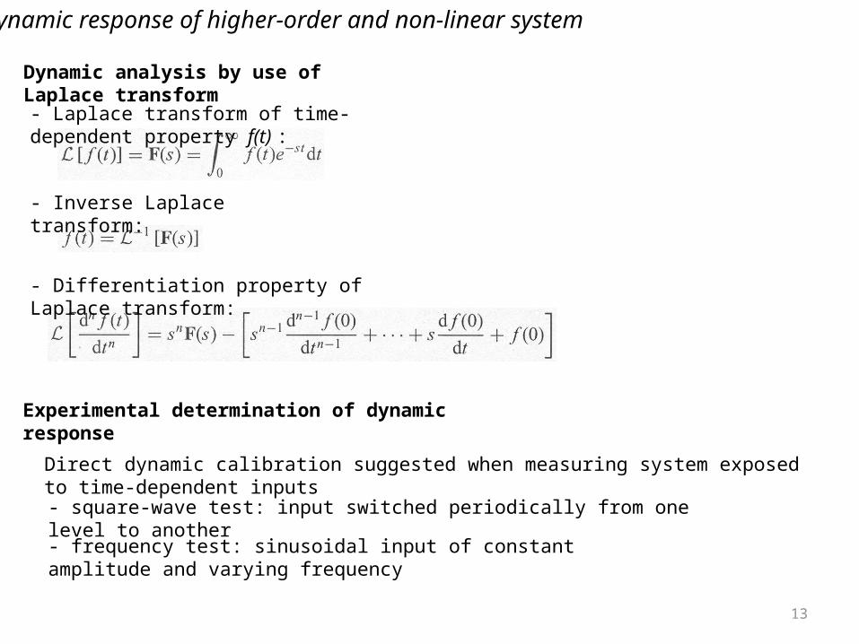
Dynamic analysis by use of Laplace transform
- Laplace transform of time-dependent property f(t) :
- Inverse Laplace transform:
- Differentiation property of Laplace transform:
Experimental determination of dynamic response
- square-wave test: input switched periodically from one level to another
- frequency test: sinusoidal input of constant amplitude and varying frequency
Direct dynamic calibration suggested when measuring system exposed to time-dependent inputs

14
Distortion, loading and cross-talk
Flow distortion
- caused by instrument inserted in flow
Loading of measuring system
- measuring component extracts significant power from flow
Instrument cross-talk
- output of one measuring component acts as undesired input to the other

15
Homework
- Questions and Problems: 10 on page 43
- Read textbook 2.3-2.4 on page 31-41
- Due on 09/02
Top Related