


Languages
Pages
Legal

© Fraunhofer
MATERIAL DEVELOPMENT AND PROCESSING ASPECTS OF CO-SINTERED CERAMIC ELECTRODES FOR ALL SOLID-STATE BATTERIES
Katja Waetzig, Jochen Schilm, B. Matthey, St. Barth, K. Nikolowski, M. Wolter
Dresden, 20th of September 2017
© Fraunhofer 2
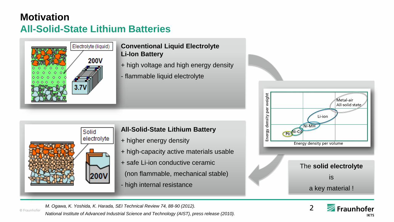
Motivation
All-Solid-State Lithium Batteries
Conventional Liquid Electrolyte
Li-Ion Battery
+ high voltage and high energy density
- flammable liquid electrolyte
M. Ogawa, K. Yoshida, K. Harada, SEI Technical Review 74, 88-90 (2012).
National Institute of Advanced Industrial Science and Technology (AIST), press release (2010).
All-Solid-State Lithium Battery
+ higher energy density
+ high-capacity active materials usable
+ safe Li-ion conductive ceramic
(non flammable, mechanical stable)
- high internal resistance
The solid electrolyte
is
a key material !
© Fraunhofer 3
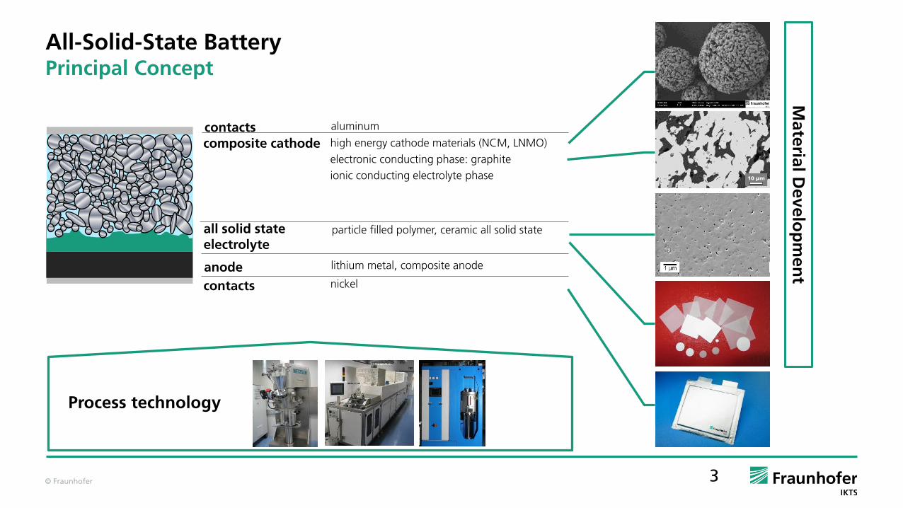
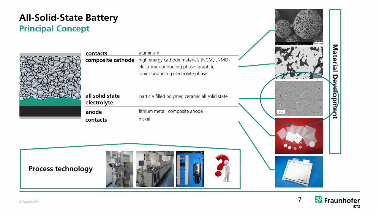
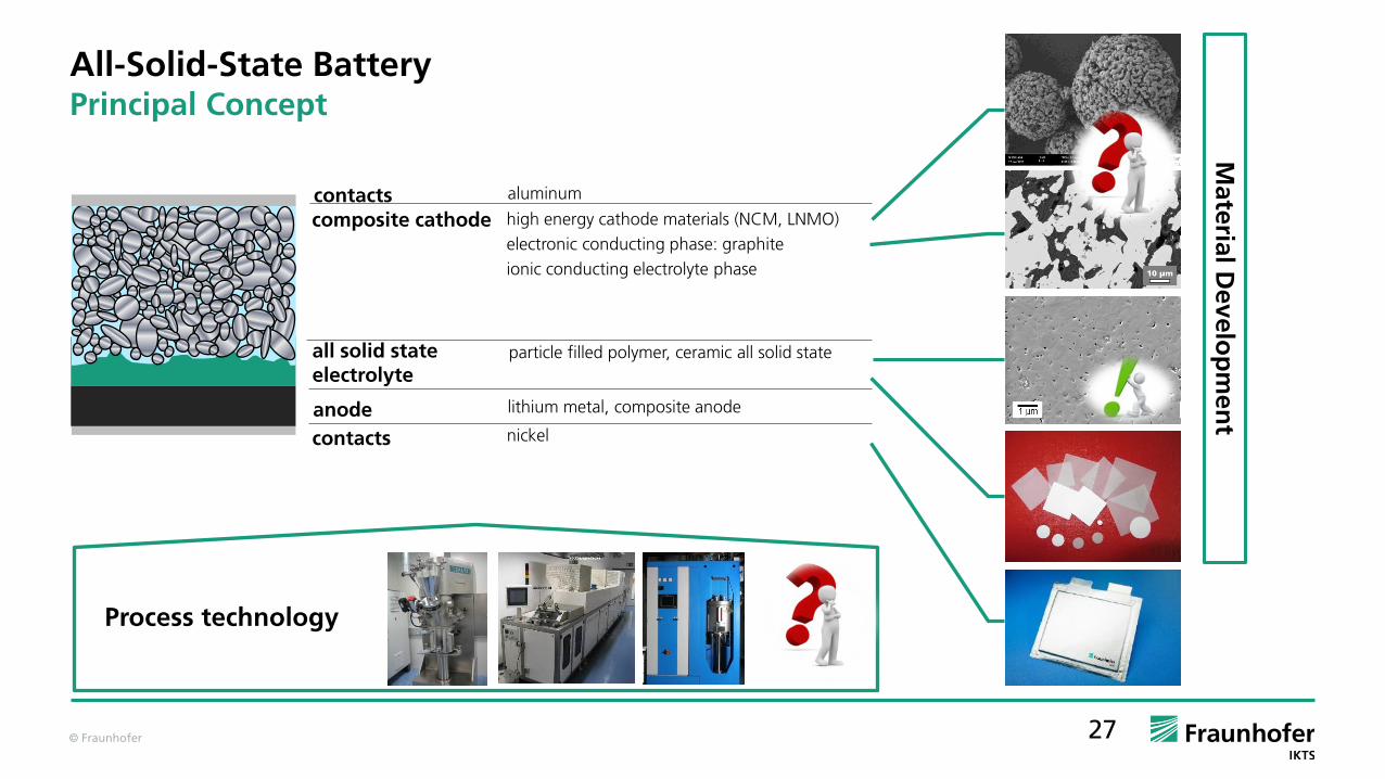
All-Solid-State BatteryPrincipal Concept
Process technology
contacts
contacts
anode
all solid state electrolyte
composite cathode
nickel
lithium metal, composite anode
particle filled polymer, ceramic all solid state
high energy cathode materials (NCM, LNMO)
electronic conducting phase: graphite
ionic conducting electrolyte phase
aluminum
Mate
rial D
evelo
pm
en
t
© Fraunhofer 4
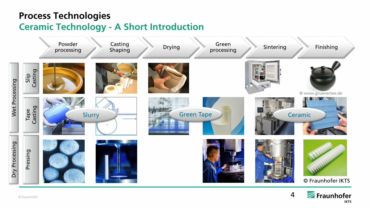
Process TechnologiesCeramic Technology - A Short Introduction
© www.gruenertee.de
Powderprocessing
Casting Shaping
DryingGreen
processingSintering Finishing
We
tP
roce
ssin
gD
ry P
roce
ssin
g
© Fraunhofer IKTS
Tap
e
Ca
stin
gSli
p
Ca
stin
gP
ress
ing
Green TapeSlurry Ceramic

© Fraunhofer 5
Processing of All-Solid-State BatteriesMultilayer as Established Ceramic Technology
Solid Oxide
Fuel Cell(SOFC)
Sensors and
Actors
Substrates
Is it possible to process All-Solid-State Batteries as multilayered ceramic?
Technology Thickness before Sintering(µm)
Thickness after Sintering(µm)
Tape Casting 50 - 500 40 - 400
Screen Printing 10 - 100 8 - 80
Other Printing Techniques < 10 < 8
© Fraunhofer 6
Powderprocessing
Casting Shaping
DryingGreen
processingSintering Finishing
electrolyte
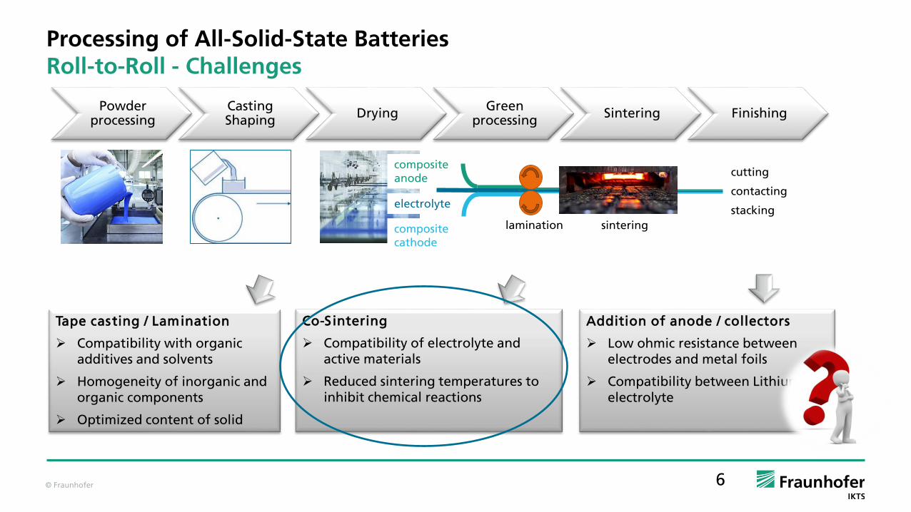
Processing of All-Solid-State BatteriesRoll-to-Roll - Challenges
compositecathode
lamination sintering
compositeanode
Tape casting / Lamination
Compatibility with organic additives and solvents
Homogeneity of inorganic and organic components
Optimized content of solid
Co-Sintering
Compatibility of electrolyte and active materials
Reduced sintering temperatures to inhibit chemical reactions
Addition of anode / collectors
Low ohmic resistance between electrodes and metal foils
Compatibility between Lithium and electrolyte
cutting
contacting
stacking
© Fraunhofer 7
All-Solid-State BatteryPrincipal Concept
Process technology
contacts
contacts
anode
all solid state electrolyte
composite cathode
nickel
lithium metal, composite anode
particle filled polymer, ceramic all solid state
high energy cathode materials (NCM, LNMO)
electronic conducting phase: graphite
ionic conducting electrolyte phase
aluminum
Mate
rial D
evelo
pm
en
t
© Fraunhofer 8
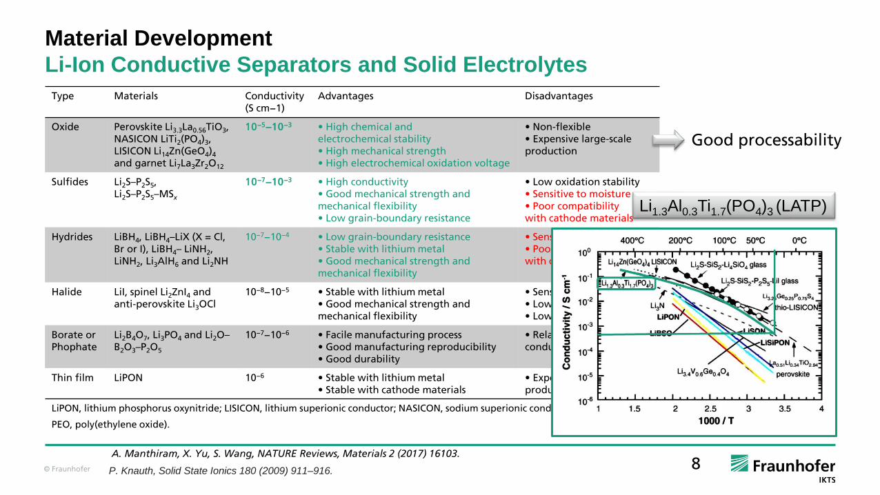
Material Development
Li-Ion Conductive Separators and Solid Electrolytes
A. Manthiram, X. Yu, S. Wang, NATURE Reviews, Materials 2 (2017) 16103.
P. Knauth, Solid State Ionics 180 (2009) 911–916.
Type Materials Conductivity(S cm−1)
Advantages Disadvantages
Oxide Perovskite Li3.3La0.56TiO3, NASICON LiTi2(PO4)3, LISICON Li14Zn(GeO4)4
and garnet Li7La3Zr2O12
10−5−10−3 • High chemical andelectrochemical stability• High mechanical strength• High electrochemical oxidation voltage
• Non-flexible• Expensive large-scaleproduction
Sulfides Li2S–P2S5, Li2S–P2S5–MSx
10−7−10−3 • High conductivity• Good mechanical strength andmechanical flexibility• Low grain-boundary resistance
• Low oxidation stability• Sensitive to moisture• Poor compatibilitywith cathode materials
Hydrides LiBH4, LiBH4–LiX (X = Cl, Br or I), LiBH4– LiNH2, LiNH2, Li3AlH6 and Li2NH
10−7−10−4 • Low grain-boundary resistance• Stable with lithium metal• Good mechanical strength andmechanical flexibility
• Sensitive to moisture• Poor compatibilitywith cathode materials
Halide LiI, spinel Li2ZnI4 and anti-perovskite Li3OCl
10−8−10−5 • Stable with lithium metal• Good mechanical strength andmechanical flexibility
• Sensitive to moisture• Low oxidation voltage• Low conductivity
Borate orPhophate
Li2B4O7, Li3PO4 and Li2O–B2O3–P2O5
10−7−10−6 • Facile manufacturing process• Good manufacturing reproducibility• Good durability
• Relatively lowconductivity
Thin film LiPON 10−6 • Stable with lithium metal• Stable with cathode materials
• Expensive large-scaleproduction
LiPON, lithium phosphorus oxynitride; LISICON, lithium superionic conductor; NASICON, sodium superionic conductor;
PEO, poly(ethylene oxide).
Good processability
Li1.3Al0.3Ti1.7(PO4)3 (LATP)
© Fraunhofer 9
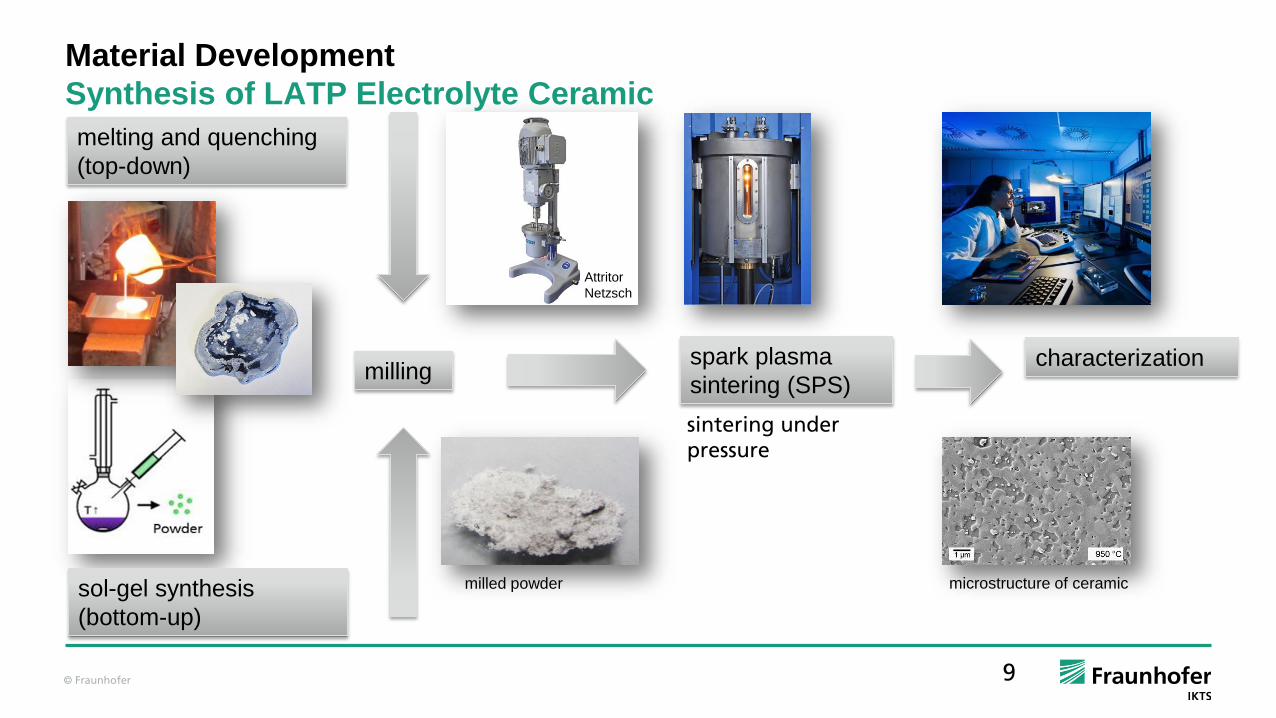
Material Development
Synthesis of LATP Electrolyte Ceramic
Attritor
Netzsch
melting and quenching
(top-down)
sol-gel synthesis
(bottom-up)
millingspark plasma
sintering (SPS)
milled powder microstructure of ceramic
characterization
sintering underpressure

© Fraunhofer 10
Material Development
Characterization of LATP Powder
Particle size distribution
comparable particle size of both
powders after intense milling
Sintering shrinkage
comparable sintering shrinkage of
both powders
Phase analysis
phase purity of synthesized
powder
secondary phases after melting
and quenching

© Fraunhofer 11
Material Development
Characterization of LATP Ceramic
Ceramic made of
synthesized and milled
powder:
fine grains
less porosity
reduced content of
secondary phases
Ceramic made of melted,
quenched and milled
powder:
fine grains
less porosity
high content of
secondary phases

© Fraunhofer 12
Highest total ionic conductivity of ceramic made of synthesized and milled LATP powder 1 .10-3 S/cm
Material Development
Characterization of LATP Ceramic
Material Development
Li conductive tapes made of LATP ceramic

© Fraunhofer 13
All-Solid-State BatteryPrincipal Concept
Process technology
contacts
contacts
anode
all solid state electrolyte
composite cathode
nickel
lithium metal, composite anode
particle filled polymer, ceramic all solid state
high energy cathode materials (NCM, LNMO)
electronic conducting phase: graphite
ionic conducting electrolyte phase
aluminum
Mate
rial D
evelo
pm
en
t

© Fraunhofer 14
Activematerial
Electronic conducting
material
Ion conductingmaterial
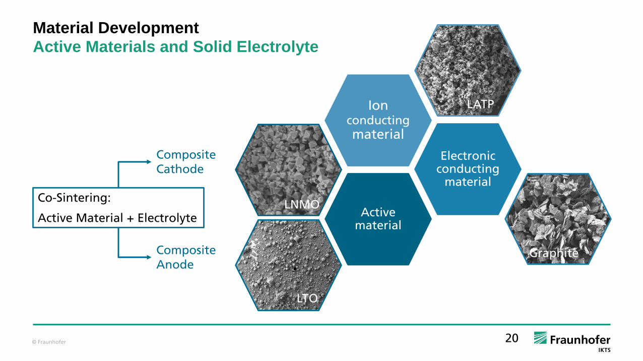
Material Development
Active Materials and Solid Electrolyte
LTO
LNMO
LATP
Graphite
Composite Cathode
Composite Anode
Co-Sintering:
Active Material + Electrolyte
© Fraunhofer 15
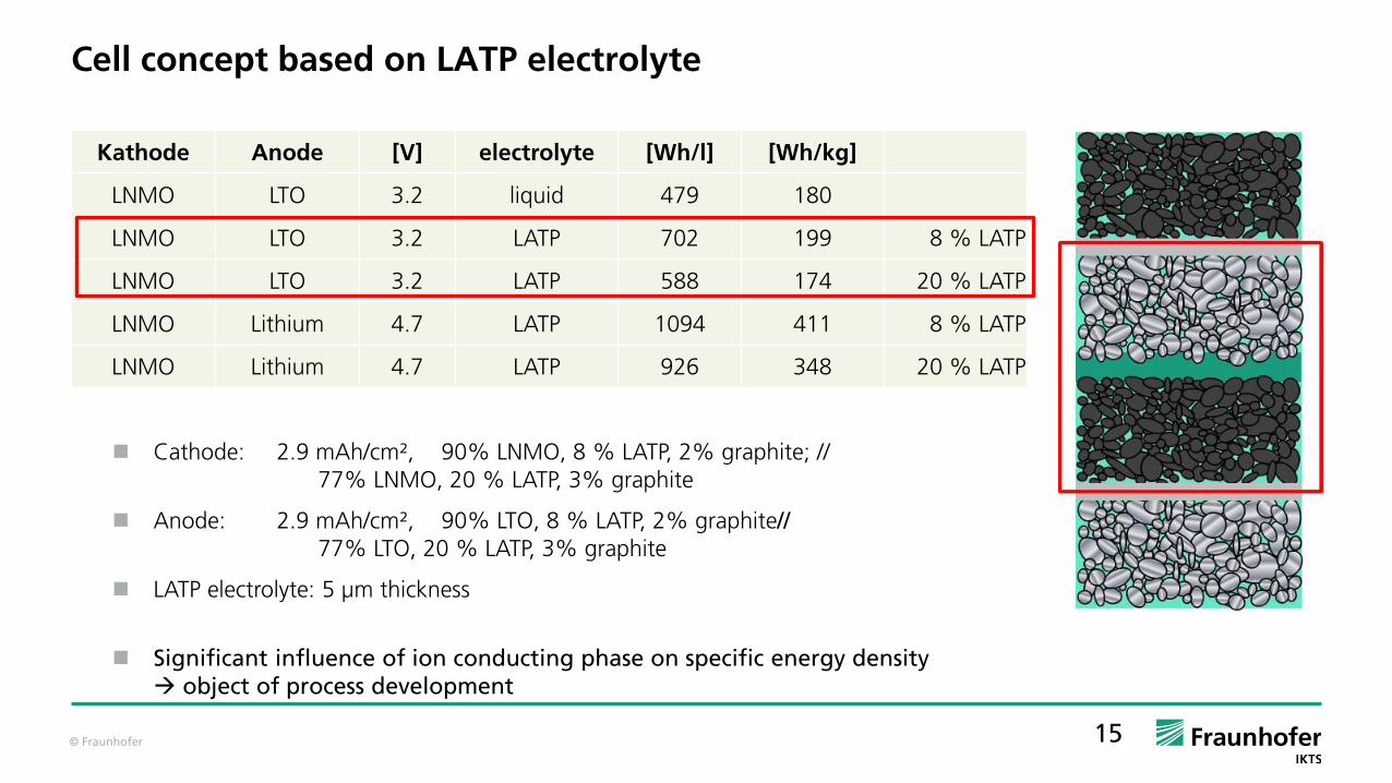
Cell concept based on LATP electrolyte
Cathode: 2.9 mAh/cm², 90% LNMO, 8 % LATP, 2% graphite; //77% LNMO, 20 % LATP, 3% graphite
Anode: 2.9 mAh/cm², 90% LTO, 8 % LATP, 2% graphite//77% LTO, 20 % LATP, 3% graphite
LATP electrolyte: 5 µm thickness
Significant influence of ion conducting phase on specific energy density object of process development
Kathode Anode [V] electrolyte [Wh/l] [Wh/kg]
LNMO LTO 3.2 liquid 479 180
LNMO LTO 3.2 LATP 702 199 8 % LATP
LNMO LTO 3.2 LATP 588 174 20 % LATP
LNMO Lithium 4.7 LATP 1094 411 8 % LATP
LNMO Lithium 4.7 LATP 926 348 20 % LATP

© Fraunhofer 16
Cell concept based on LATP electrolyte
Kathode Anode [V] electrolyte [Wh/l] [Wh/kg]
LNMO LTO 3.2 liquid 479 180
LNMO LTO 3.2 LATP 702 199 8 % LATP
LNMO LTO 3.2 LATP 588 174 20 % LATP
LNMO Lithium 4.7 LATP 1094 411 8 % LATP
LNMO Lithium 4.7 LATP 926 348 20 % LATP
Lithium Anode Composite Anode made of LTO / LATP
+ higher potential difference (4.7 V)
+ increased energy density per volume / weight
+ processing with conventional technologies
+ no safety risk
+ no dendrite growth
+ high rate capability
- Processing under inert atmosphere
- higher safety risk
- dendrite growth
- lower potential difference (3.2 V)
- moderate energy density per volume / weight

© Fraunhofer
Material Development – Composite CathodePowder synthesis of cathode material LiNi0.5Mn1.5O4 (LNMO)
Investigation of synthesis parameters for material
properties adapted to solid state battery application
Scale up spray drying process, granulate particles
parameters for LNMO-synthesis
Precursor composition nucleation, morphology acetate-salts
Pre-Calcination (T, t) homogeneity 5 h at 800 °C followed by grinding
Calcination (T, t) phase, crystallite size additional 5 h at 800 °C
g kg
© Fraunhofer 18
0.01 0.1 1 10 1000
1
2
3
4
5
6
q3(x
) (1
/d)
particel size distribution (µm)
LNMO
1 3 5 7 9 11 15 20 25 55 60 65 710
20
40
60
80
100
120
140
LNMO
sp
ecific
ca
pa
city (
mA
h/g
)
cyclenumber
0,1
C
1 C
1 C
2 C
0,5
C
0,1
C
0,2
C
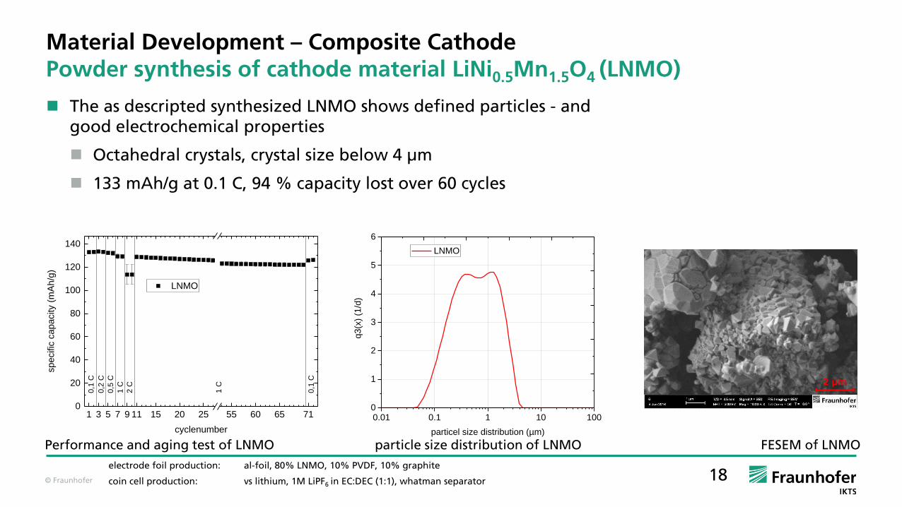
Performance and aging test of LNMO particle size distribution of LNMO
electrode foil production: al-foil, 80% LNMO, 10% PVDF, 10% graphite
coin cell production: vs lithium, 1M LiPF6 in EC:DEC (1:1), whatman separator
FESEM of LNMO
2 µm
The as descripted synthesized LNMO shows defined particles - and good electrochemical properties
Octahedral crystals, crystal size below 4 µm
133 mAh/g at 0.1 C, 94 % capacity lost over 60 cycles
Material Development – Composite CathodePowder synthesis of cathode material LiNi0.5Mn1.5O4 (LNMO)
© Fraunhofer 19
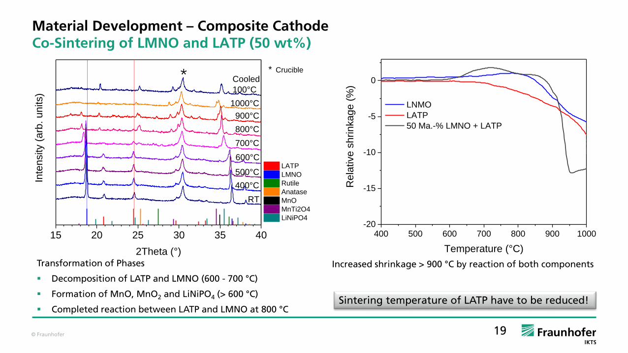
Material Development – Composite CathodeCo-Sintering of LMNO and LATP (50 wt%)
Transformation of Phases
Decomposition of LATP and LMNO (600 - 700 °C)
Formation of MnO, MnO2 and LiNiPO4 (> 600 °C)
Completed reaction between LATP and LMNO at 800 °C
Increased shrinkage > 900 °C by reaction of both components
15 20 25 30 35 40
Cooled
100°C
600°C
1000°C
800°C
900°C
700°C
500°C
400°C
Inte
nsity (
arb
. u
nits)
2Theta (°)
RT
* Crucible
LATP
LMNO
Rutile
Anatase
MnO
MnTi2O4
LiNiPO4
*
400 500 600 700 800 900 1000-20
-15
-10
-5
0
Re
lative
sh
rin
ka
ge
(%
)
Temperature (°C)
LNMO
LATP
50 Ma.-% LMNO + LATP
Sintering temperature of LATP have to be reduced!
© Fraunhofer 20
Activematerial
Electronic conducting
material
Ion conductingmaterial
Material Development
Active Materials and Solid Electrolyte
LTO
LNMO
LATP
Graphite
Composite Cathode
Composite Anode
Co-Sintering:
Active Material + Electrolyte

© Fraunhofer 21
Material Development – Composite Anode
Commercial Li4Ti5O12 material
Commercial powder from Huntsman; Hombitec LTO5
Measured capacity 169 mAh/g (at 0.1 C) in conventional electrode morphology
Only slightly sintered agglomerates; primary particles <1µm particle size good characteristics for solid state electrodes

© Fraunhofer 22
Material Development – Composite Anode
Co-Sintering of LTO and LATP (50 wt%)
Transformation of Phases
Formation of Anatase (> 500 °C)
Transformation of Anatase Rutile (> 800 °C)
Formation of Li3PO4 (> 600 °C)
Completed reaction between LATP and LTO at 1000 °C
Increased shrinkage > 820 °C by reaction of both components
15 20 25 30 35 40
Cooled
100°C
600°C
1000°C
800°C
900°C
700°C
500°C
400°C
Inte
nsity (
arb
. un
its)
2Theta (°)
RT
* Crucible
LATP
LTO
Rutile
Anatase
Li3PO4
*
400 500 600 700 800 900 1000-20
-15
-10
-5
0
Rela
tive s
hri
nka
ge
(%
)
Temperature (°C)
LTO
LATP
50 Ma.-% LTO + LATP

© Fraunhofer
Sintering Densityg/cm³
ConductivityS/cm
LATP SPS 850°C 2.82 (97%) 5 * 10-4
LATP+LTO SPS 850 °C 3.23 (~100%) not measurable
No continuous pathways of Li conductive LATP electrolyte through microstructure
Granules
Dense phase
Reaction zonearound granule
Reaction zone arounddense phase
Microstructure of Spark Plasma Sintered LTO and LATP mixture (850 °C)
Theoretical DensitiesLATP: 2.92 g/cm³LTO: 3.48 g/cm3
50 wt% LATP and 50 wt% LTO: 3.20 g/cm³
Material Development – Composite Anode
Co-Sintering of LTO and LATP (50 wt%)
© Fraunhofer
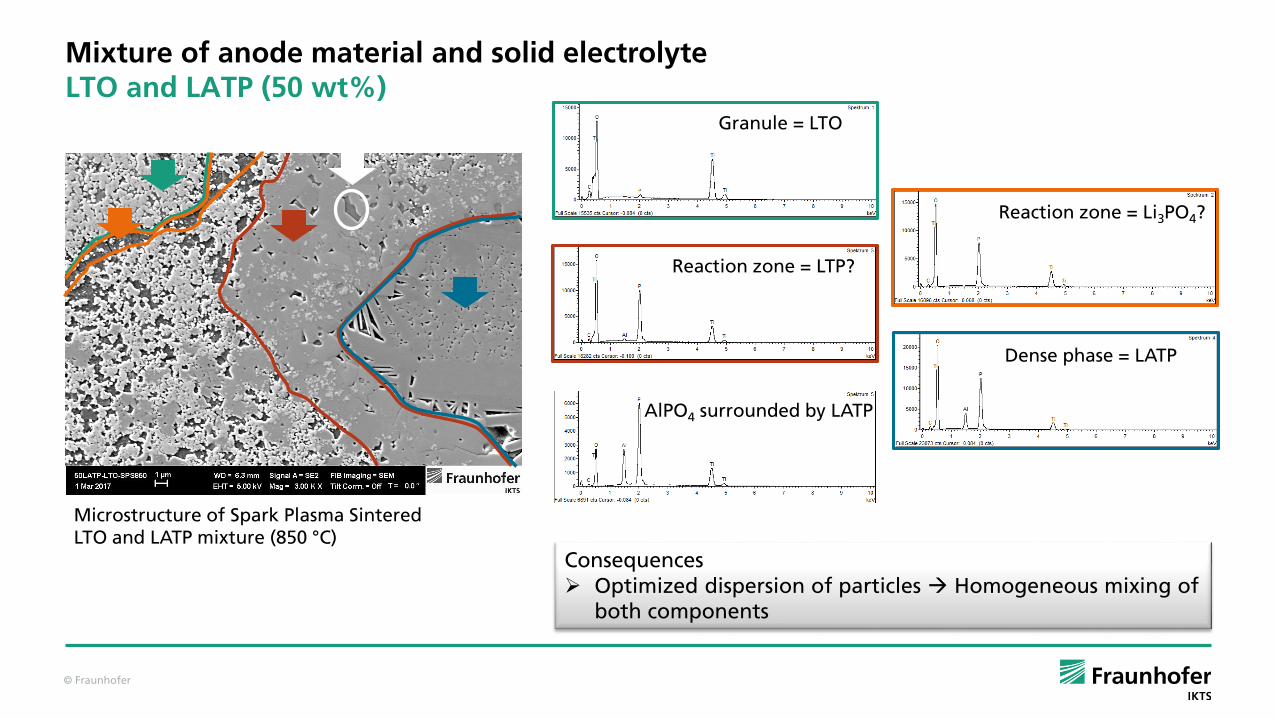
Consequences Optimized dispersion of particles Homogeneous mixing of
both components
Mixture of anode material and solid electrolyteLTO and LATP (50 wt%)
Microstructure of Spark Plasma SinteredLTO and LATP mixture (850 °C)
Granule = LTO
Reaction zone = Li3PO4?
AlPO4 surrounded by LATP
Reaction zone = LTP?
Dense phase = LATP

© Fraunhofer
Sintering Densityg/cm³
ConductivityS/cm
low intensive mixing
LATP SPS 850°C 2.82 (97%) 5 * 10-4
LATP+LTO SPS 850 °C 3.23 (~100%) not measurable
high intensive mixing
LATP+LTO SPS 850°C 3.01 (81.1%) not measurable
LATP+LTO SPS 750°C 2.23 (69.6%) 9 * 10-7
Pathway of Li conductive LATP electrolyte through microstructure Inhomogeneous microstructure
Microstructure of LTO and LATP mixture (SPS 750 °C)
Theoretical DensitiesLATP: 2.92 g/cm³LTO: 3.48 g/cm3
50 wt% LATP and 50 wt% LTO: 3.20 g/cm³
Material Development – Composite Anode
Co-Sintering of LTO and LATP (50 wt%)

© Fraunhofer 26
Materials DevelopmentConclusion
Temperatures for co-sintering should be:Anode < 500 ° C; Cathode < 600 ° C
Next Steps:
Investigation of graphite stability in binary and ternary mixtures of electrode materials
Investigation of mixing parameters for optimum dispersion of the particles (percolating network of LATP and graphite)
Investigation of approaches to liquid phase sintering reduction of sintering temperatures
Optimization of densification of the electrode microstructure (minimum porosity)
© Fraunhofer 27
All-Solid-State BatteryPrincipal Concept
Process technology
contacts
contacts
anode
all solid state electrolyte
composite cathode
nickel
lithium metal, composite anode
particle filled polymer, ceramic all solid state
high energy cathode materials (NCM, LNMO)
electronic conducting phase: graphite
ionic conducting electrolyte phase
aluminum
Mate
rial D
evelo
pm
en
t
© Fraunhofer 28
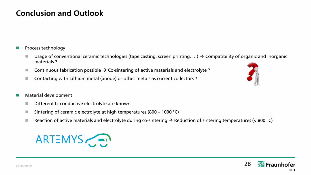
Conclusion and Outlook
Process technology
Usage of conventional ceramic technologies (tape casting, screen printing, …) Compatibility of organic and inorganic materials ?
Continuous fabrication possible Co-sintering of active materials and electrolyte ?
Contacting with Lithium metal (anode) or other metals as current collectors ?
Material development
Different Li-conductive electrolyte are known
Sintering of ceramic electrolyte at high temperatures (800 – 1000 °C)
Reaction of active materials and electrolyte during co-sintering Reduction of sintering temperatures (< 800 °C)

© Fraunhofer 29
Acknowledgement
Department of M. Kusnezoff – Fraunhofer IKTS
I. Eichler, K. Jungnickel, C. Frey, D. Wagner, A. Rost, M. Fritsch, V. Sauchuk
Department of M. Wolter – Fraunhofer IKTS
C. Heubner, A. Nickol, M. Seidel
Department of M. Herrmann – Fraunhofer IKTS
A. Potthoff, M. Striegler, B. Weise, and colleagues
“KerFolyt” funded by the Fraunhofer internal program MEF (Grant No. 600660)
“EMBATT1.0” funded by the Europäische Fonds für regionale Entwicklung (EFRE) and the Freistaat Sachsen
“EMBATT2.0” funded by the German Federal Ministry of Education and Research BMBF (No. 03XP0068G)
“ARTEMYS” funded by the German Federal Ministry of Education and Research BMBF
www.ikts.fraunhofer.de
Thank you for your attention!
Top Related