


Languages
Pages
Legal


Nano Res
1
Mass production of Co3O4@CeO2 core@shell
nanowires for catalytic CO oxidation
Jiangman Zhena,b #, Xiao Wanga #, Dapeng Liua (), Zhuo Wanga,b, Junqi Lia,b, Fan Wanga,b,
Yinghui Wanga and Hongjie Zhanga ()
Nano Res., Just Accepted Manuscript • DOI: 1 10.1007/s01274-015-0704-3
http://www.thenanoresearch.com on December 24 2014
© Tsinghua University Press 2014
Just Accepted
This is a “Just Accepted” manuscript, which has been examined by the peer-review process and has been
accepted for publication. A “Just Accepted” manuscript is published online shortly after its acceptance,
which is prior to technical editing and formatting and author proofing. Tsinghua University Press (TUP)
provides “Just Accepted” as an optional and free service which allows authors to make their results available
to the research community as soon as possible after acceptance. After a manuscript has been technically
edited and formatted, it will be removed from the “Just Accepted” Web site and published as an ASAP
article. Please note that technical editing may introduce minor changes to the manuscript text and/or
graphics which may affect the content, and all legal disclaimers that apply to the journal pertain. In no event
shall TUP be held responsible for errors or consequences arising from the use of any information contained
in these “Just Accepted” manuscripts. To cite this manuscript please use its Digital Object Identifier (DOI®),
which is identical for all formats of publication.
Nano Research
DOI 10.1007/s01274-015-0704-3
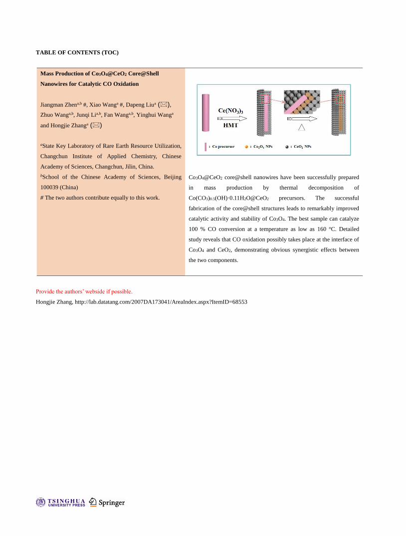
TABLE OF CONTENTS (TOC)
Mass Production of Co3O4@CeO2 Core@Shell
Nanowires for Catalytic CO Oxidation
Jiangman Zhena,b #, Xiao Wanga #, Dapeng Liua (),
Zhuo Wanga,b, Junqi Lia,b, Fan Wanga,b, Yinghui Wanga
and Hongjie Zhanga ()
aState Key Laboratory of Rare Earth Resource Utilization,
Changchun Institute of Applied Chemistry, Chinese
Academy of Sciences, Changchun, Jilin, China.
bSchool of the Chinese Academy of Sciences, Beijing
100039 (China)
# The two authors contribute equally to this work.
Co3O4@CeO2 core@shell nanowires have been successfully prepared
in mass production by thermal decomposition of
Co(CO3)0.5(OH)·0.11H2O@CeO2 precursors. The successful
fabrication of the core@shell structures leads to remarkably improved
catalytic activity and stability of Co3O4. The best sample can catalyze
100 % CO conversion at a temperature as low as 160 oC. Detailed
study reveals that CO oxidation possibly takes place at the interface of
Co3O4 and CeO2, demonstrating obvious synergistic effects between
the two components.
Provide the authors’ webside if possible.
Hongjie Zhang, http://lab.datatang.com/2007DA173041/AreaIndex.aspx?ItemID=68553
Mass Production of Co3O4@CeO2 Core@Shell
Nanowires for Catalytic CO Oxidation
Jiangman Zhena,b #, Xiao Wanga #, Dapeng Liua (), Zhuo Wanga,b, Junqi Lia,b, Fan Wanga,b, Yinghui
Wanga and Hongjie Zhanga ()
Received: day month year
Revised: day month year
Accepted: day month year
(automatically inserted by
the publisher)
© Tsinghua University Press
and Springer-Verlag Berlin
Heidelberg 2014
KEYWORDS
Co3O4@CeO2, core@shell,
nanowires, CO oxidation,
synergistic effects
ABSTRACT
In this paper, Co3O4@CeO2 core@shell nanowires were successfully prepared via
thermal decomposition of Co(CO3)0.5(OH)·0.11H2O@CeO2 core@shell nanowire
precursors. As the CO oxidation catalyst, Co3O4@CeO2 shows remarkably
enhanced catalytic performance compared to Co3O4 nanowires and CeO2 NPs,
demonstrating obvious synergistic effects between the two components. It also
suggests that the CeO2 shell coating can effectively keep Co3O4 nanowires from
agglomeration, and hence remarkably improve the structure stability of Co3O4
catalyst. And the fabrication of the well dispersed core@shell structure results in
a maximized interface area between Co3O4 and CeO2 as well as a smaller Co3O4
size, which might be responsible for the enhanced catalytic activity of
Co3O4@CeO2. Further study reveals that CO oxidation possibly takes place at
the interface of Co3O4 and CeO2. The influence of calcination temperatures and
component ratio between Co3O4 and CeO2 have been then investigated in detail
on the catalytic performance of Co3O4@CeO2 core@shell nanowires, the best of
which obtained by calcination at 250 oC for 3 h with a Ce molar content about
38.5 % can catalyze 100 % CO conversion at a lower temperature of 160 oC.
More importantly more than 2.5 g of the Co3O4@CeO2 core@shell nanowires can
be produced in one pot by this simple process, which would be beneficial to
their practical applications as automobile exhaust gas treatment catalysts.

www.theNanoResearch.com∣www.Springer.com/journal/12274 | Nano Research
2 Nano Res.
1 Introduction
Catalytic oxidation of carbon monoxide (CO) has
drawn continuous attention because of the serious
health effects associated with exposure to CO.
Co3O4, a typical spinel-structure transition metal
oxide, has been subjected to intense interest recently
due to its excellent ability for catalytic CO oxidation,
and has been regarded as an alternative to noble
metal catalysts[1-5]. Co3O4 nanorods synthesized by
Xie’s group have shown good catalytic performance,
which can catalyze CO oxidation at a low
temperature of –77 oC in a trace moist stream of
normal feed gas[2]. They attributed this to the
abundance of active Co3+ species on {110} planes of
the Co3O4 nanorods. Besides, the size of Co3O4
nanostructure is also thought to be important in
determining its catalytic activity[4,5]. However, there
is still few reports concerning optimizing the
stability of Co3O4 catalysts, because for practical
needs, catalysts are often required to be working at
relatively high temperatures without removing a
mass of streams. Under such conditions,
nanomaterials are apt to aggregate or deform,
resulting in heavy loss of catalytic active centers
and serious catalytic deterioration and even
inactivation. Therefore, the synthesis of Co3O4
catalysts with high activity as well as stability has
become an area of great focus in material science.
Fabrication of core@shell structures has been
identified as an efficient way to inhibit agglomeration
so as to improve the stability of nanomaterials[6-15]. In
this consideration numerous kinds of oxides, such as
CeO2, SiO2, and ZrO2, have been adopted as the
stable shell components[6,7,8,12,15]. In particular, CeO2, a
typical kind of multifunctional rare earth oxide,
receives intense attention due to its wide applications
in catalysis[16-25]. It possesses strong oxygen storage
capacity that makes it highly active in oxidation
reaction. More importantly, it can also show excellent
synergistic effects with other catalytic active
components. For instance, Ag@CeO2, Pt@CeO2,
Au@CeO2 and Pd@CeO2 core@shell catalysts have
exhibited good activity and high-temperature
stability as oxidation reaction catalysts[12,22-25]. Hence
it is reasonably considered that the activity as well as
the stability of Co3O4 catalyst could be optimized
through the facile fabrication of Co3O4@CeO2
core@shell structures.
Generally, core@shell structures are synthesized
through hydrolysis of the precursors to deposit the
shell component onto a preformed core[25]. However,
it is necessary to do some surface modification on the
core in advance so as to avoid independent
nucleation of the shell component. This
layer-by-layer technology is a multistep process that
requires precise control and complex surface
modification, so it is not conducive to large-scale
synthesis and has seriously limited the practical
applications of such catalysts. Besides, the reverse
micelle method can be used to prepare core@shell
structures[6,9]. However, the synthetic procedure is
also multistep and consumes considerable time and
energy. Meanwhile, to get the specific core@shell
structures, organic species such as surfactants have
been largely used[25,26], some of which are hard to be
removed completely, and hence the catalytic active
centers of nanocatalysts might be contaminated,
resulting in unsatisfactory catalytic activity.
Consequently, it seems more meaningful to develop
an effective way to realize the facile, clean and mass
production of Co3O4@CeO2 core@shell structures.
Here, we report the synthesis of high-quality
Co3O4@CeO2 core@shell structures in gram level.
First, Co(CO3)0.5(OH)·0.11H2O nanowires were
prepared as precursors[27], and then they were
coated by a CeO2 shell followed by the previously
reported strategy[28]. After calcination in air, the
as-obtained Co(CO3)0.5(OH)·0.11H2O@CeO2
core@shell nanowires can be thermally decomposed
and transformed into the final monodisperse
Address correspondence to Dapeng Liu, [email protected]; Hongjie Zhang, [email protected]

www.theNanoResearch.com∣www.Springer.com/journal/12274 | Nano Research
3 Nano Res.
Co3O4@CeO2 core@shell nanowires built up by
Co3O4 and CeO2 nanoparticles (NPs). In order to
investigate the transformation process, thermal
gravimetric analysis (TGA) of
Co(CO3)0.5(OH)·0.11H2O@CeO2 has been done in
combination with the CO catalytic test, X-ray
diffraction (XRD), scanning electron microscope
(SEM) and transmission electron microscopic (TEM)
analyses. Then the influence of calcination
temperatures on the catalytic performance of
Co3O4@CeO2 core@shell nanowires was
systematically investigated to study the optimal
condition for catalytic CO oxidation.
2 Experimental
Preparation of Co(CO3)0.5(OH)·0.11H2O nanowires
(Co precursor): Co(CO3)0.5(OH)·0.11H2O nanowires
were synthesized by a previously reported
hydrothermal procedure[27]. Typically, 0.56 g of
CoSO4·7H2O was dissolved in 40 mL of a mixture
containing 7 mL of glycerol and 33 mL of deionized
water. After stirred for about 10 min, a transparent
solution was obtained, into which 0.10 g of urea
was then added. 30 min later, the solution was
transferred into a 50 mL Teflon-lined stainless steel
autoclave, followed by heating at 170 oC for a
period of 24 h in an electric oven. Afterwards the
autoclave was cooled naturally to room
temperature. The products were collected and
washed with deionized water and ethanol for three
times by centrifugation, and then dried at 60 oC
overnight.
Preparation of Co(CO3)0.5(OH)·0.11H2O@CeO2
core@shell nanowires (Co precursor@CeO2): 0.1 g of
Co(CO3)0.5(OH)·0.11H2O nanowires were
ultrasonically dispersed in a mixed solution of 50
mL of water and 50 mL of ethanol, and then 0.65
mmol Ce(NO3)3 and 20 mL of 0.02 g/mL
hexamethylenetetramine (HMT) aqueous solution
were added in turn. Then the temperature of the
solution was increased to 70 oC and refluxed for 2 h
before cooled to room temperature. The products
were purified by centrifugation and washed with
deionized water and ethanol for three times, and
then dried at 60 oC and named as
Co(CO3)0.5(OH)·0.11H2O@CeO2-1. By tuning the
amount of Ce(NO3)3 and HMT, another three
Co(CO3)0.5(OH)·0.11H2O@CeO2 precursors were
synthesized followed by the above procedure, and
the as-obtained products were named as
Co(CO3)0.5(OH)·0.11H2O@CeO2-2 (1.3 mmol
Ce(NO3)3, 30 mL of HMT solution),
Co(CO3)0.5(OH)·0.11H2O@CeO2-3 (0.325 mmol
Ce(NO3)3, 10 mL of HMT solution) and
Co(CO3)0.5(OH)·0.11H2O@CeO2-4 (0.16 mmol
Ce(NO3)3, 5 mL of HMT solution), respectively.
Preparation of Co3O4@CeO2 core@shell
nanowires: The precursor of
Co(CO3)0.5(OH)·0.11H2O@CeO2-1 were calcined at
250, 350 and 500 oC for 3 h in air, and the
corresponding products are named as
Co3O4@CeO2-1-250, Co3O4@CeO2-1-350 and
Co3O4@CeO2-1-500, respectively. For control,
Co(CO3)0.5(OH)·0.11H2O@CeO2-2, -3, and –4 were all
calcined at 250 oC for 3 h in air as well, and the
corresponding products were named as
Co3O4@CeO2-2-250, Co3O4@CeO2-3-250, and
Co3O4@CeO2-4-250, respectively.
Preparation of Co3O4 nanowires:
Co(CO3)0.5(OH)·0.11H2O nanowires were directly
calcined at 250 oC for 3 h in air.
Preparation of Co3O4-CeO2 hybrids: 0.03 g of the
as-prepared Co3O4 nanowires were ultrasonically
dispersed in a mixed solution of 12 mL of water and
12 mL of ethanol, and then 0.24 mmol Ce(NO3)3 and
10 mL of 0.02 g/mL HMT aqueous solution were
added in turn. Then the temperature of the solution
was increased to 70 oC and refluxed for 2 h before
being cooled to room temperature. The products
were purified by centrifugation and washed with
deionized water and ethanol for three times, and
then dried at 60 oC.
Preparation of pure CeO2 NPs: 1 mmol Ce(NO3)3
was dissolved in a mixed solution of 20 mL of

www.theNanoResearch.com∣www.Springer.com/journal/12274 | Nano Research
4 Nano Res.
deionized water and 20 mL of ethanol. Then 25 mL
of 0.02 g/mL HMT aqueous solution was added.
Then the temperature of the mixture was increased
to 70 oC and refluxed for 2 h before being cooled to
room temperature. The products were purified by
centrifugation and washed with deionized water
and ethanol for three times, and then dried at 60 oC.
Finally, the products were calcined in air at 250 oC
for 3 h in air.
Preparation of Co3O4-CeO2 mixtures: 0.058 g of
the above mentioned Co3O4 nanowires and 0.042 g
of CeO2 NPs were physical mixed by grinding in an
agate mortar for half an hour.
Characterization: The XRD data of the products
were collected on a Rigaku-D/max 2500 V X-ray
diffractometer with Cu-K radiation ( = 1.5418 Å ),
with an operation voltage and current maintained
at 40 kV and 40 mA. TEM images were obtained
with a TECNAI G2 high-resolution transmission
electron microscope operating at 200 kV. A
HITACHI S-4800 field emission scanning electron
microscope (FE-SEM) was used to characterize the
morphology of the samples. X-ray photoelectron
spectroscopy (XPS) measurement was performed
on an ESCALAB-MKII 250 photoelectron
spectrometer (VG Co.) with Al-K X-ray radiation
as the X-ray source for excitation. TGA curves of the
sample was acquired by using a SDT 2960 thermal
analyzer at a heating rate of 10 oC min-1 in air
atmosphere within a temperature range between 20
and 700 oC. A GC 9800 gas chromatography tester
was employed to obtain the CO conversion curves
of the samples. N2 sorption isotherms were
obtained at 77 K on an Auto-sorb-1 apparatus.
Inductively coupled plasma (ICP) analyses were
performed with a Varian Liberty 200
spectrophotometer to determine the Ce content.
H2-temperature-programmed reduction (TPR) was
conducted on a TPDRO 1100 apparatus supplied by
Thermo-Finnigan Company. Before detection by the
TCD, the gas was purified by a trap containing CaO
+ NaOH materials in order to remove the H2O and
CO2. For each time, 30 mg of the sample was heated
from room temperature to 900 °C at a rate of
10 °C/min. A gaseous mixture of 5 vol. % H2 in N2
was used as reductant at a flow rate of 20 mL/min.
Catalytic tests: 25 mg of catalysts were put in a
stainless steel reaction tube. The CO oxidation
catalytic tests were performed under an atmosphere
of 1 % CO and 20 % O2 in N2 at a fixed space
velocity of 50 mL/min. The composition of the gas
was monitored on-line by gas chromatography.
3 Results and discussion
Figure 1. (A) SEM and (B and C) TEM images of Co precursor;
(D) SEM and (E and F) TEM images of Co precursor@CeO2
(Inset: HRTEM of CeO2).
Scheme 1. Schematic process for preparation of Co3O4@CeO2
core@shell nanowires.
The as-obtained samples were characterized by
SEM and TEM. From the SEM and TEM images
(Figure 1A to 1C), it can be clearly seen that Co
precursor is composed by uniform and well
dispersed nanowires with several micrometres in
length and tens of nanometers in width. After

www.theNanoResearch.com∣www.Springer.com/journal/12274 | Nano Research
5 Nano Res.
coated with a CeO2 shell, the smooth surface of Co
precursor nanowire becomes obviously rough
(Figure 1D to 1F), indicating the success of CeO2
shell coating process. The as-prepared products
well keep the wire-like morphology as Co precursor
and each nanowire is completely wrapped by a
shell built up by hundreds of 6 nm sized CeO2 NPs
self-assembled together. The inset in Figure 1F
shows the lattice spacing of 0.31 nm which
corresponds well to the characteristic (111) plane of
fluorite-phase CeO2. Combining with the XRD
results (Figure S1) it firmly demonstrates the
core@shell structure formation of
Co(CO3)0.5(OH)·0.11H2O@CeO2. More than 3 g of
Co(CO3)0.5(OH)·0.11H2O@CeO2 can be obtained in
one pot (see Figure S2), and its schematic
fabrication has been summarized to a two-step
process as described in Scheme 1.
Catalytic oxidation of CO is chosen here as the
model reaction to evaluate the catalytic
performance of the samples. In order to study the
details about the transformation of
Co(CO3)0.5(OH)·0.11H2O as well as its influence on
the catalytic performance, the CO oxidation cycling
tests of Co(CO3)0.5(OH)·0.11H2O@CeO2-1 have been
done in the temperature range from 50 to 250 oC. As
shown in Figure 2 and S3, it can be found that
during the tests the value of T100 (the temperature
for 100 % CO conversion) kept decreasing until the
fifth cycle to 160 oC and then remained stable at 160
oC in the following cycles. In general, catalysts often
degrade more or less under long-term and
high-temperature catalytic conditions due to
aggregation, growth or some other reasons like
poisoning. The abnormal enhancement of the
catalytic activity aroused our great interests to
investigate this phenomenon in depth.
As reported by Lou, et al[27], the transformation of
Co(CO3)0.5(OH)·0.11H2O to Co3O4 starts at about 200
oC, so it is considered that such transformation
would proceed during the catalytic process. Firstly,
TGA was employed to get the detailed information
of the decomposition process of
Co(CO3)0.5(OH)·0.11H2O@CeO2-1. Figure 3 shows
that the major weight loss (about 10 %) takes place
in the temperature range of 230 to 300 °C, which is
in consistence with its corresponding DSC analysis
(Figure S4). This part of loss should be attributed to
the decomposition of carbonates and hydroxide
groups of Co(CO3)0.5(OH)·0.11H2O[27].
Coincidentally, the first cycling curve of CO
conversion fully supports the TGA-DSC results that
above 230 °C the sample can totally catalyze CO
oxidation due to the transformation of
Co(CO3)0.5(OH)·0.11H2O into Co3O4.
1 2 3 4 5 6 7 8 9 100
50
100
150
200
250
StableT100 (
oC
)
Cycle
Decrease
Figure 2. Cycling tests of Co(CO3)0.5(OH)·0.11H2O@CeO2-1
for CO conversion.
50 100 150 200 250 300 350
0
20
40
60
80
100
70
80
90
100
110
120
Wei
ght
Los
s (%
)
CO
Con
vers
ion
(%
)
Temperature (oC)
Figure 3. TGA curve and the first cycling curve of CO
conversion of Co(CO3)0.5(OH)·0.11H2O@CeO2-1.
www.theNanoResearch.com∣www.Springer.com/journal/12274 | Nano Research
6 Nano Res.
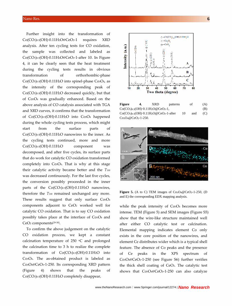
Further insight into the transformation of
Co(CO3)0.5(OH)·0.11H2O@CeO2-1 requires XRD
analysis. After ten cycling tests for CO oxidation,
the sample was collected and labeled as
Co(CO3)0.5(OH)·0.11H2O@CeO2-1-after 10. In Figure
4, it can be clearly seen that the heat treatment
during the cycling tests results in obvious
transformation of orthorhombic-phase
Co(CO3)0.5(OH)·0.11H2O into spinel-phase Co3O4, as
the intensity of the corresponding peak of
Co(CO3)0.5(OH)·0.11H2O decreased quickly, but that
of Co3O4 was gradually enhanced. Based on the
above analysis of CO catalysis associated with TGA
and XRD curves, it confirms that the transformation
of Co(CO3)0.5(OH)·0.11H2O into Co3O4 happened
during the whole cycling tests process, which might
start from the surface parts of
Co(CO3)0.5(OH)·0.11H2O nanowires to the inner. As
the cycling tests continued, more and more
Co(CO3)0.5(OH)·0.11H2O component was
decomposed, and after five cycles, its surface parts
that do work for catalytic CO oxidation transformed
completely into Co3O4. That is why at this stage
their catalytic activity became better and the T100
was decreased continuously. For the last five cycles,
the conversion possibly proceeded in the inner
parts of the Co(CO3)0.5(OH)·0.11H2O nanowires,
therefore the T100 remained unchanged any more.
These results suggest that only surface Co3O4
components adjacent to CeO2 worked well for
catalytic CO oxidation. That is to say CO oxidation
possibly takes place at the interface of Co3O4 and
CeO2 components[29-30].
To confirm the above judgement on the catalytic
CO oxidation process, we kept a constant
calcination temperature of 250 oC and prolonged
the calcination time to 3 h to realize the complete
transformation of Co(CO3)0.5(OH)·0.11H2O into
Co3O4. The as-obtained product is labeled as
Co3O4@CeO2-1-250. Its corresponding XRD pattern
(Figure 4) shows that the peaks of
Co(CO3)0.5(OH)·0.11H2O completely disappear,
Figure 4. XRD patterns of (A)
Co(CO3)0.5(OH)·0.11H2O@CeO2-1, (B)
Co(CO3)0.5(OH)·0.11H2O@CeO2-1-after 10 and (C)
Co3O4@CeO2-1-250.
Figure 5. (A to C) TEM images of Co3O4@CeO2-1-250, (D
and E) the corresponding EDX mapping analysis.
while the peak intensity of Co3O4 becomes more
intense. TEM (Figure 5) and SEM images (Figure S5)
show that the wire-like structure maintained well
after either CO catalytic test or calcination.
Elemental mapping indicates element Co only
exists in the core position of the nanowires, and
element Ce distributes wider which is a typical shell
feature. The absence of Co peaks and the presence
of Ce peaks in the XPS spectrum of
Co3O4@CeO2-1-250 (see Figure S6) further verifies
the thick shell coating of CeO2. The catalytic test
shows that Co3O4@CeO2-1-250 can also catalyze
www.theNanoResearch.com∣www.Springer.com/journal/12274 | Nano Research
7 Nano Res.
100 % CO conversion at 160 oC (see Figure 6) which
is the same with that of
Co(CO3)0.5(OH)·0.11H2O@CeO2-1-after 10. All these
proofs point to the fact that
Co(CO3)0.5(OH)·0.11H2O@CeO2 should go through a
intermediate core@shell@shell state of
Co(CO3)0.5(OH)·0.11H2O@Co3O4@CeO2, and finally
turns into Co3O4@CeO2, as described in Scheme 1.
Despite the difference of the core components
between Co(CO3)0.5(OH)·0.11H2O@Co3O4-1-after 10
and Co3O4@CeO2-1-250, they show much similar
catalytic activities, firmly indicating that only those
surface Co3O4 components interfaced with CeO2 do
work well for catalytic CO oxidation.
50 100 150 200 250 300 3500
20
40
60
80
100
Co3O
4 @CeO
2-1-250
Co
nv
ersi
on
of
CO
(%
)
Temperature (oC)
Figure 6. CO conversion curve of Co3O4@CeO2-1-250.
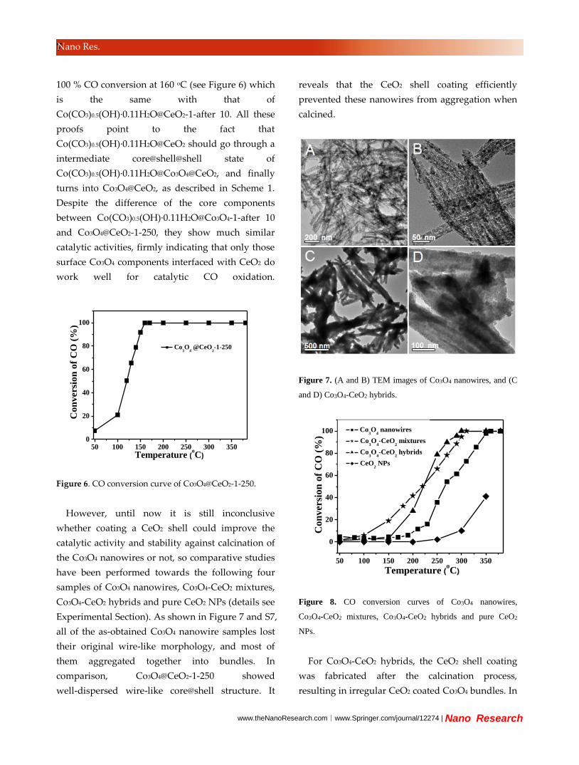
However, until now it is still inconclusive
whether coating a CeO2 shell could improve the
catalytic activity and stability against calcination of
the Co3O4 nanowires or not, so comparative studies
have been performed towards the following four
samples of Co3O4 nanowires, Co3O4-CeO2 mixtures,
Co3O4-CeO2 hybrids and pure CeO2 NPs (details see
Experimental Section). As shown in Figure 7 and S7,
all of the as-obtained Co3O4 nanowire samples lost
their original wire-like morphology, and most of
them aggregated together into bundles. In
comparison, Co3O4@CeO2-1-250 showed
well-dispersed wire-like core@shell structure. It
reveals that the CeO2 shell coating efficiently
prevented these nanowires from aggregation when
calcined.
Figure 7. (A and B) TEM images of Co3O4 nanowires, and (C
and D) Co3O4-CeO2 hybrids.
50 100 150 200 250 300 350
0
20
40
60
80
100
Con
ver
sio
n o
f C
O (
%)
Temperature (oC)
Co3O
4 nanowires
Co3O
4-CeO
2 mixtures
Co3O
4-CeO
2 hybrids
CeO2 NPs
Figure 8. CO conversion curves of Co3O4 nanowires,
Co3O4-CeO2 mixtures, Co3O4-CeO2 hybrids and pure CeO2
NPs.
For Co3O4-CeO2 hybrids, the CeO2 shell coating
was fabricated after the calcination process,
resulting in irregular CeO2 coated Co3O4 bundles. In

www.theNanoResearch.com∣www.Springer.com/journal/12274 | Nano Research
8 Nano Res.
other words, the CeO2 shell coating should proceed
before calcined, so Co3O4 nanowires could be
efficiently prevented from aggregation during the
calcination process, resulting in the remarkably
improved structure stability of Co3O4 catalysts. The
sizes of Co3O4 NPs in Co3O4 nanowires, Co3O4-CeO2
mixtures and Co3O4-CeO2 hybrids are 9.9, 10.0 and
10.1 nm, respectively (XRD patterns see Figure S8),
calculated by the Scherrer equation. Whereas the
Co3O4 NPs in Co3O4@CeO2-1-250 show a much
smaller size of about 5.9 nm. Obviously, the coating
of CeO2 shell leads to much smaller Co3O4 NPs,
which might be responsible for the optimization of
the catalytic activity.
In the following, the influence of the CeO2 shell
was discussed on the catalytic activity of Co3O4
catalysts. As shown in Figure 8, Co3O4 nanowires
can catalyze 100 % CO conversion at 360 oC. More
worse, the CO conversion for pure CeO2 NPs was
only 40 % at 350 oC. While Co3O4-CeO2 mixtures
and Co3O4-CeO2 hybrids can catalyze 100 % CO
conversion at lower temperatures of about 320 and
300 oC, respectively. The enhancement of their
catalytic activities could be ascribed to the
synergistic effects between Co3O4 and CeO2.29-31
However, Co3O4@CeO2-1-250 can catalyze 100 % CO
conversion at a much lower temperature of 160 oC.
The optimal catalytic activity of Co3O4@CeO2-1-250
compared to Co3O4-CeO2 mixtures and Co3O4-CeO2
hybrids could be ascribed to the fabrication of the
well-dispersed core@shell structures explained by
the following points: (1) the maximized interface
area resulting from the well-dispersed core@shell
structure, which is beneficial for CO oxidation; (2)
the smaller Co3O4 size resulted from the effective
CeO2 shell coating of the core@shell structure. This
comparative test well supports the above
hypothesis that the fabrication of Co3O4@CeO2
core@shell structures is efficient to optimize the
catalytic activity and stability of Co3O4 catalysts.
As known, calcination process is fundamentally
important to exert a significant impact on the
physical and chemical properties of materials[3,33].
Calcination time, calcination atmosphere, especially
calcination temperature could greatly affect the
catalytic performance of the catalysts[12,26]. So the
effects of calcination temperature need to be further
investigated towards our core@shell catalysts.
Co(CO3)0.5(OH)·0.11H2O@CeO2-1 precursors were
then calcined at 350 and 500 oC, and thus obtained
products are named as Co3O4@CeO2-1-350 and
Co3O4@CeO2-1-500, respectively. As shown in
Figure S9 and S10, Co3O4@CeO2-1-350 and
Co3O4@CeO2-1-500 are in similar wire-like
core@shell structures compared with
Co3O4@CeO2-1-250.
Figure 9. XRD patterns of (A) Co3O4@CeO2-1-250, (B)
Co3O4@CeO2-1-350, and (C) Co3O4@CeO2-1-500.
XRD patterns in Figure 9 present that the peaks of
CeO2 show no difference among Co3O4@CeO2-1-250,
Co3O4@CeO2-1-350 and Co3O4@CeO2-1-500.
However, there are some obvious differences of the
Co3O4 peaks among the three samples. As the
calcination temperature was increased from 250 oC
to 350 oC to 500 oC, the intensity of the Co3O4 peaks
become stronger, and the peaks become sharper
indicating its better crystallinity of
Co3O4@CeO2-1-500 than Co3O4@CeO2-1-350 than
Co3O4@CeO2-1-250. The size of the Co3O4 NPs are
5.9, 10.1 and 12.7 nm for Co3O4@CeO2-1-250,
Co3O4@CeO2-1-350 and Co3O4@CeO2-1-500,

www.theNanoResearch.com∣www.Springer.com/journal/12274 | Nano Research
9 Nano Res.
respectively. The XPS spectra of Co3O4@CeO2-1-350
and Co3O4@CeO2-1-500 in Figure S11 both show five
Ce peaks and no obvious Co peaks, which are
similar to Co3O4@CeO2-1-250. It suggests both
Co3O4@CeO2-1-350 and Co3O4@CeO2-1-500 have the
similar shell coating of CeO2 compared to
Co3O4@CeO2-1-250. The N2 adsorption–desorption
isotherm of the three samples is depicted in Figure
S12, indicating Type IV behavior of nanoporous
Co3O4@CeO2-1-250, Co3O4@CeO2-1-350 and
Co3O4@CeO2-1-500 with high surface area of 144.9,
121.4, 64.0 m2g-1 and average pore width of 6.14,
8.11, 9.79 nm, respectively.
The test of catalytic CO oxidation (Figure 10) was
then conducted to evaluate the catalytic
performance of Co3O4@CeO2-1-350 and
Co3O4@CeO2-1-500 compared with Co3O4@CeO2-250.
The T100 of the three Co3O4@CeO2 samples follows
such an order: Co3O4@CeO2-1-250 (160 °C) <
Co3O4@CeO2-1-350 (250 °C) < Co3O4@CeO2-1-500 (>
380 °C). Co3O4@CeO2-1-250, which is obtained by
calcination at the lowest temperature shows the
highest catalytic activity. In order to study the
synergetic effects of Co3O4 and CeO2, the catalysts
were investigated by H2-TPR. Two broad TPR
peaks (Figure 11A) observed at 380 °C and 750 °C
50 100 150 200 250 300 350
0
20
40
60
80
100
Co
nv
ersi
on
of
CO
(%
)
Temperature (oC)
Co3O
4@CeO
2-1-350
Co3O
4@CeO
2-1-500
Figure 10. CO conversion curves of Co3O4@CeO2-1-350 and
Co3O4@CeO2-1-500.
200 400 600 800
× 3
× 3
E
D
C
B
403 oC
750 oC
308 oC
380 oC
374 oC
410 oC
420 oC
316 oC
357 oC
750 oC
750 oC
487 oC
Temperature (oC)
Inte
nsi
ty (
a.u
.)
750 oC
A
× 3
Figure 11. H2-TPR profiles: (A) pure CeO2; (B) Co3O4
nanowires; (C) Co3O4@CeO2-1-500; (D) Co3O4@CeO2-1-350
and (E) Co3O4@CeO2-1-250.
for CeO2 can be attributed to the reduction of
surface capping oxygen and bulk oxygen of CeO2,
respectively[12,32]. The two peaks at around 374 °C
and 487 °C in Figure 11B could be attributed to the
two reduction steps of Co3O4 species[1]. It can be
seen from Figure 11C-E that the Co3O4 reduction
peaks of Co3O4@CeO2-1-250, Co3O4@CeO2-1-350 and
Co3O4@CeO2-1-500 all shifted towards lower
temperature to about 308, 316, 357 oC for the first
peak and 403, 410, 420 oC for the second peak,
respectively, indicating a typical synergistic effect
between Co3O4 and CeO2. The previous work
reported that the a lower calcination temperature
favors reducing the degree of Co3O4@CeO2 interface
breakage that improves the oxidizability of Co3O4.26
That is why the oxidizability of Co3O4 in these
samples follows such a sequence that
Co3O4@CeO2-1-250 > Co3O4@CeO2-1-350 >
Co3O4@CeO2-1-500, which is in agreement with the
changing trends of their catalytic activities. If we
enlarge the curve in the temperature range of
650 °C to 900 °C for three times, the signal at 750 °C
for CeO2 could be still clearly seen, indicating the
existence of bulk oxygen of CeO2. Based on the
www.theNanoResearch.com∣www.Springer.com/journal/12274 | Nano Research
10 Nano Res.
above results and discussions, it is concluded that
the optimal catalytic activity of Co3O4@CeO2-1-250
can be ascribed to the following reasons. (1) better
oxidizability of Co3O4, which might be caused by
the lower degree of Co3O4@CeO2 interface breakage
resulting from the lower calcination temperature[26];
(2) the smaller sized Co3O4 NPs than the other two
samples; (3) the bigger BET surface area than the
other two samples[34]; (4) worse crystallinity of
Co3O4@CeO2-1-250 that might bring more surface
defects and thus higher surface energy, which are in
favor of the CO adsorption, resulting in the optimal
catalytic activity for CO oxidation[3].
Besides calcination temperatures, the component
ratio of hetero-catalysts also play a significant role in
the catalytic performance[32]. So by simply varying
the amount of Ce(NO3)3, a series of Co3O4@CeO2
core@shell nanowires have been synthesized to
investigate the effects of component ratio between
Co3O4 and CeO2 on their catalytic activities. The
corresponding samples are named as
Co3O4@CeO2-2-250, Co3O4@CeO2-3-250, and
Co3O4@CeO2-4-250 (experimental details see
Experimental Section). As shown in Figure S13 and
S14, the three comparative samples show similar
core@shell wire-like structure to Co3O4@CeO2-1-250,
except for the CeO2 shell thickness. The average
diameters of Co3O4@CeO2 core@shell nanowires,
estimated by the size distribution data, are 120, 95, 65,
and 53 nm for Co3O4@CeO2-2-250, Co3O4@CeO2-1-250,
Co3O4@CeO2-3-250, and Co3O4@CeO2-4-250
respectively, indicating that the corresponding
average CeO2 shell thicknesses become thinner and
thinner. The Co and Ce contents were determined by
ICP-MS. As shown in Table S1, the Ce molar contents
are 50.3 %, 38.5 %, 18.2 % and 8.9 % for
Co3O4@CeO2-2-250, Co3O4@CeO2-1-250,
Co3O4@CeO2-3-250, and Co3O4@CeO2-4-250,
respectively. Figure S15 presents the XRD patterns of
Co3O4@CeO2-2-250, Co3O4@CeO2-3-250, and
Co3O4@CeO2-4-250 that he peak positions and shapes
of the three samples are the same with
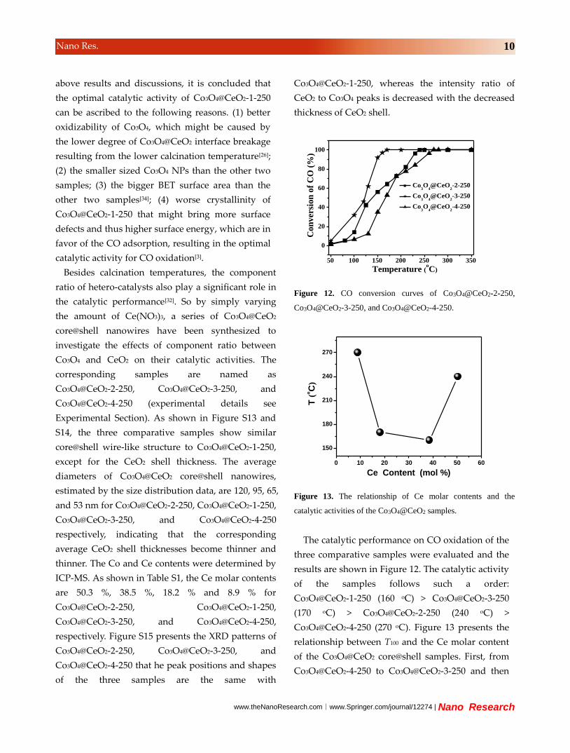
Co3O4@CeO2-1-250, whereas the intensity ratio of
CeO2 to Co3O4 peaks is decreased with the decreased
thickness of CeO2 shell.
50 100 150 200 250 300 350
0
20
40
60
80
100
Co3O
4@CeO
2-2-250
Co3O
4@CeO
2-3-250
Co3O
4@CeO
2-4-250
Co
nv
ersi
on
of
CO
(%
)
Temperature (oC)
Figure 12. CO conversion curves of Co3O4@CeO2-2-250,
Co3O4@CeO2-3-250, and Co3O4@CeO2-4-250.
0 10 20 30 40 50 60
150
180
210
240
270
T (
oC
)
Ce Content (mol %)
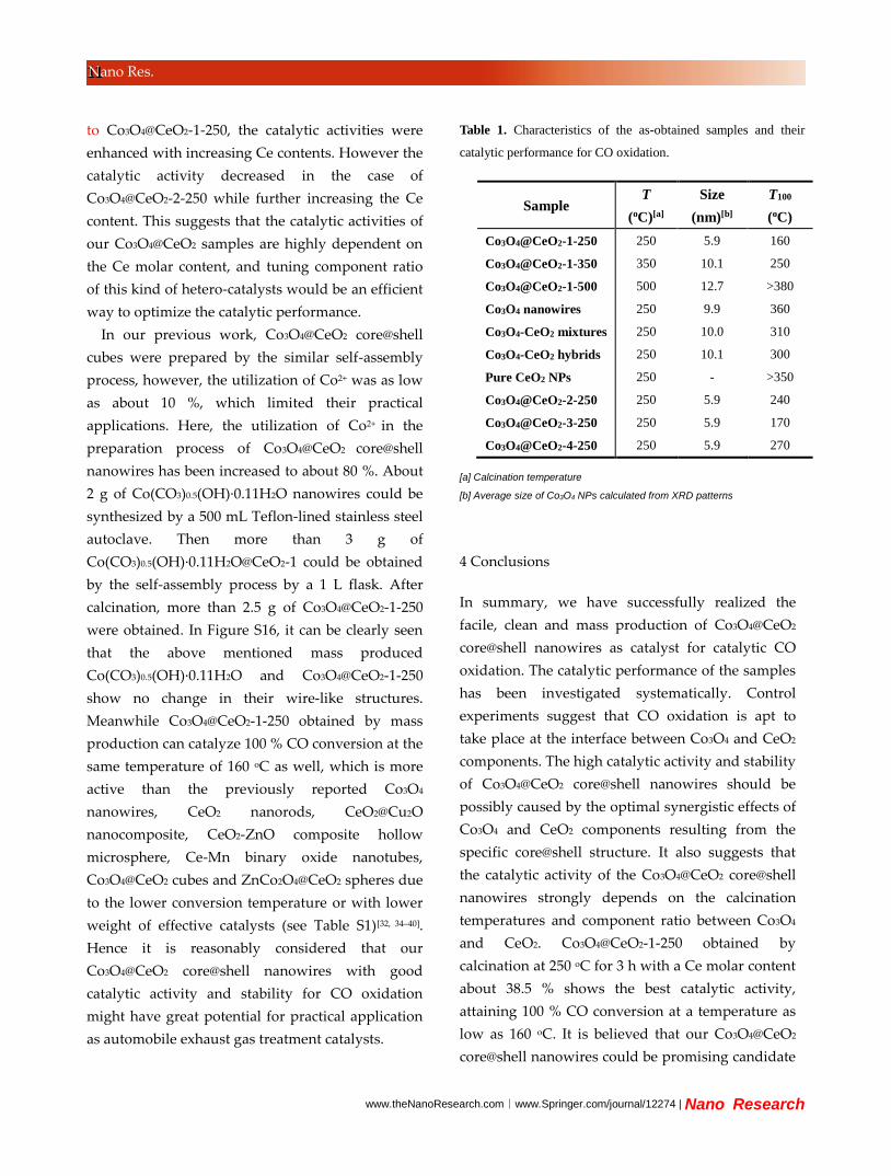
Figure 13. The relationship of Ce molar contents and the
catalytic activities of the Co3O4@CeO2 samples.
The catalytic performance on CO oxidation of the
three comparative samples were evaluated and the
results are shown in Figure 12. The catalytic activity
of the samples follows such a order:
Co3O4@CeO2-1-250 (160 oC) > Co3O4@CeO2-3-250
(170 oC) > Co3O4@CeO2-2-250 (240 oC) >
Co3O4@CeO2-4-250 (270 oC). Figure 13 presents the
relationship between T100 and the Ce molar content
of the Co3O4@CeO2 core@shell samples. First, from
Co3O4@CeO2-4-250 to Co3O4@CeO2-3-250 and then
www.theNanoResearch.com∣www.Springer.com/journal/12274 | Nano Research
11 Nano Res.
to Co3O4@CeO2-1-250, the catalytic activities were
enhanced with increasing Ce contents. However the
catalytic activity decreased in the case of
Co3O4@CeO2-2-250 while further increasing the Ce
content. This suggests that the catalytic activities of
our Co3O4@CeO2 samples are highly dependent on
the Ce molar content, and tuning component ratio
of this kind of hetero-catalysts would be an efficient
way to optimize the catalytic performance.
In our previous work, Co3O4@CeO2 core@shell
cubes were prepared by the similar self-assembly
process, however, the utilization of Co2+ was as low
as about 10 %, which limited their practical
applications. Here, the utilization of Co2+ in the
preparation process of Co3O4@CeO2 core@shell
nanowires has been increased to about 80 %. About
2 g of Co(CO3)0.5(OH)·0.11H2O nanowires could be
synthesized by a 500 mL Teflon-lined stainless steel
autoclave. Then more than 3 g of
Co(CO3)0.5(OH)·0.11H2O@CeO2-1 could be obtained
by the self-assembly process by a 1 L flask. After
calcination, more than 2.5 g of Co3O4@CeO2-1-250
were obtained. In Figure S16, it can be clearly seen
that the above mentioned mass produced
Co(CO3)0.5(OH)·0.11H2O and Co3O4@CeO2-1-250
show no change in their wire-like structures.
Meanwhile Co3O4@CeO2-1-250 obtained by mass
production can catalyze 100 % CO conversion at the
same temperature of 160 oC as well, which is more
active than the previously reported Co3O4
nanowires, CeO2 nanorods, CeO2@Cu2O
nanocomposite, CeO2-ZnO composite hollow
microsphere, Ce-Mn binary oxide nanotubes,
Co3O4@CeO2 cubes and ZnCo2O4@CeO2 spheres due
to the lower conversion temperature or with lower
weight of effective catalysts (see Table S1)[32, 34–40].
Hence it is reasonably considered that our
Co3O4@CeO2 core@shell nanowires with good
catalytic activity and stability for CO oxidation
might have great potential for practical application
as automobile exhaust gas treatment catalysts.
Table 1. Characteristics of the as-obtained samples and their
catalytic performance for CO oxidation.
[a] Calcination temperature
[b] Average size of Co3O4 NPs calculated from XRD patterns
4 Conclusions
In summary, we have successfully realized the
facile, clean and mass production of Co3O4@CeO2
core@shell nanowires as catalyst for catalytic CO
oxidation. The catalytic performance of the samples
has been investigated systematically. Control
experiments suggest that CO oxidation is apt to
take place at the interface between Co3O4 and CeO2
components. The high catalytic activity and stability
of Co3O4@CeO2 core@shell nanowires should be
possibly caused by the optimal synergistic effects of
Co3O4 and CeO2 components resulting from the
specific core@shell structure. It also suggests that
the catalytic activity of the Co3O4@CeO2 core@shell
nanowires strongly depends on the calcination
temperatures and component ratio between Co3O4
and CeO2. Co3O4@CeO2-1-250 obtained by
calcination at 250 oC for 3 h with a Ce molar content
about 38.5 % shows the best catalytic activity,
attaining 100 % CO conversion at a temperature as
low as 160 oC. It is believed that our Co3O4@CeO2
core@shell nanowires could be promising candidate
Sample T
(oC)[a]
Size
(nm)[b]
T100
(oC)
Co3O4@CeO2-1-250
Co3O4@CeO2-1-350
Co3O4@CeO2-1-500
Co3O4 nanowires
Co3O4-CeO2 mixtures
Co3O4-CeO2 hybrids
Pure CeO2 NPs
Co3O4@CeO2-2-250
Co3O4@CeO2-3-250
Co3O4@CeO2-4-250
250
350
500
250
250
250
250
250
250
250
5.9
10.1
12.7
9.9
10.0
10.1
-
5.9
5.9
5.9
160
250
>380
360
310
300
>350
240
170
270

www.theNanoResearch.com∣www.Springer.com/journal/12274 | Nano Research
12 Nano Res.
catalysts for CO oxidation as automobile exhaust
gas treatment catalysts. This work supplies a
feasible way to fabricate core@shell structures for
the exploration and optimization of this kind of
hetero-nanocatalysts.
Acknowledgements
This work was supported by the financial aid from
the National Natural Science Foundation of China
(Grant Nos. 91122030, 51272249, 21210001, 21221061
and 21401186), and the National Key Basic Research
Program of China (No. 2014CB643802).
Electronic Supplementary Material: Supplementary
material is available in the online version of this
article at http://dx.doi.org/10.1007/s12274-***-****-*
(automatically inserted by the publisher). References
[1] Hu, L. H.; Sun, K. Q.; Peng, Q.; Xu, B. Q.; Li, Y. D.
Surface active sites on Co3O4 nanobelt and nanocube
model catalysts for CO oxidation. Nano Res. 2010, 3,
363–368.
[2] Xie, X. W.; Li, Y.; Liu, Z. Q.; Haruta, M.; Shen, W. J.
Low-temperature oxidation of CO catalysed by Co3O4
nanorods. Nature 2009, 458, 746–749.
[3] Song, W. Q.; Poyraz, Al. S.; Meng, Y. T.; Ren, Z.; Chen,
S. Yu.; Suib, S. L. Mesoporous Co3O4 with controlled
porosity: inverse micelle synthesis and high-performance
catalytic CO oxidation at −60° C. Chem. Mater. 2014, 26,
4629−4639.
[4] Pandey, A. D.; Jia, C. J.; Schmidt, W. S.; Leoni, M.;
Schwickardi, M.; Schu th, F.; Weidenthaler, C.
Size-controlled synthesis and microstructure investigation
of Co3O4 nanoparticles for low-temperature CO oxidation.
J. Phys. Chem. C 2012, 116, 19405−19412.
[5] Jia, C. J.; Schwickardi, M.; Weidenthaler, C.; Schmidt, W.;
Korhonen, S.; Weckhuysen, B. M.; Schuth, F. Co3O4-SiO2
nanocomposite: a very active catalyst for CO oxidation
with unusual catalytic behavior. J. Am. Chem. Soc. 2011,
133, 11279–11288.
[6] Lu, Z. H.; Jiang, H. L.; Yadav, M.; Aranishi, K.; Xu, Q.
Synergistic catalysis of Au-Co@SiO2 nanospheres in
hydrolytic dehydrogenation of ammonia borane for
chemical hydrogen storage. J. Mater. Chem. 2012, 22,
5065–5071.
[7] Arnal, P. M.; Comotti, M.; Schuth, F.
High-temperature-stable catalysts by hollow sphere
encapsulation. Angew. Chem. Int. Ed. 2006, 45,
8224–8227.
[8] Ge, J. P.; Zhang, Q.; Zhang, T. R.; Yin, Y. D.
Core-satellite nanocomposite catalysts protected by a
porous silica shell; controllable reactivity, high stability,
and magnetic recyclability. Angew. Chem. Int. Ed. 2008,
47, 8924–8928.
[9] Zhang, T. T.; Zhao, H. Y.; He, S. N.; Liu, K.; Liu, H. Y.;
Yin, Y. D.; Gao, C. B. Unconventional route to
encapsulated ultrasmall gold nanoparticles for
high-temperature catalysis. Acs. Nano. 2014, 8,
7297–7304.
[10] Yu, K.; Wu, Z. C.; Zhao, Q. R.; Li, B. X.; Xie, Y.
High-temperature-stable Au@SnO2 core/shell supported
catalyst for CO oxidation. J. Phys. Chem. C 2008, 112,
2244–2247.
[11] Zhou, H. P.; Wu, H. S.; Shen, J.; Yin, A. X.; Sun, L. D.;
Yan, C. H. Thermally stable Pt/CeO2
hetero-nanocomposites with high catalytic activity. J. Am.
Chem. Soc. 2010, 132, 4998–4999.
[12] Zhang, J.; Li, L. P.; Huang, X. S.; Li, G. S. Fabrication of
Ag–CeO2 core–shell nanospheres with enhanced catalytic
performance due to strengthening of the interfacial
interactions. J. Mater. Chem. 2012, 22, 10480–10487.
[13] Lee, I.; Zhang, Q.; Ge, J. P.; Yin, Y. D.; Zaera, F.
Encapsulation of supported Pt nanoparticles with
mesoporous silica for increased catalyst stability. Nano
Res. 2011, 4, 115–123.
[14] Chen, J. C.; Zhang, R. Y.; Han, L.; Tu, B.; Zhao, D. Y.
One-pot synthesis of thermally stable gold@mesoporous
silica core–shell nanospheres with catalytic activity. Nano
Res. 2013, 6, 871–879.
[15] Zhang, N.; Xu, Y. J. Aggregation- and leaching-resistant,

www.theNanoResearch.com∣www.Springer.com/journal/12274 | Nano Research
13 Nano Res.
reusable, and multifunctional Pd@CeO2 as a robust
nanocatalyst achieved by a hollow core–shell strategy.
Chem. Mater. 2013, 25, 1979–1988.
[16] Feng, L.; Hoang, D. T.; Tsung, C. K.; Huang, W. Y.; Lo,
S. H. Y.; Wood, J. B.; Wang, H.; Tang, J. Y.; Yang, P. D.
Catalytic properties of Pt cluster-decorated CeO2
nanostructures. Nano Res. 2011, 4, 61–71.
[17] Zhang, Y.; Hou, F.; Tan, Y. W. CeO2 nanoplates with a
hexagonal structure and their catalytic applications in
highly selective hydrogenation of substituted
nitroaromatics. Chem. Commun. 2012, 48, 2391–2393.
[18] Lee, Y. J.; He, G. H.; Akey, A. J.; Si, R.; Stephanopoulos,
M. F.; Herman, I. P. Raman analysis of mode softening in
nanoparticle CeO2-δ and Au-CeO2-δ during CO oxidation.
J. Am. Chem. Soc. 2011, 133, 12952–12955.
[19] Xu, L. S; Ma, Y. S.; Zhang, Y. L.; Jiang, Z. Q.; Huang, W.
X. Direct evidence for the interfacial oxidation of CO
with hydroxyls catalyzed by Pt/Oxide nanocatalysts. J.
Am. Chem. Soc. 2009, 131, 16366–16367.
[20] Tian, J.; Sang, Y. H.; Zhao, Z. H.; Zhou, W. J.; Wang, D.
Z.; Kang, X. L.; Liu, H.; Wang, J. Y.; Chen, S. W.; Cai, H.
Q.; Huang, H. Enhanced photocatalytic performances of
CeO2/TiO2 nanobelt heterostructures. Small 2013, 9,
3864–3872.
[21] Mak, A. C.; Yu, C. L.; Yu, Ji. C.; Zhang, Z. D.; Ho, C. A
lamellar ceria structure with encapsulated platinum
nanoparticles. Nano Res. 2008, 1, 474–482.
[22] Wang, X.; Liu, D. P.; Song, S. Y.; Zhang, H. J. Pt@CeO2
multicore@shell self-assembled nanospheres: clean
synthesis, structure optimization, and catalytic
applications. J. Am. Chem. Soc. 2013, 135, 15864−15872.
[23] Kayama, T.; Yamazaki, K.; Shinjoh, H. Nanostructured
ceria-silver synthesized in a one-pot redox reaction
catalyzes carbon oxidation. J. Am. Chem. Soc. 2010, 132,
13154–13155.
[24] Guo, H.; He, Y. B.; Wang, Y. P.; Liu, L. X.; Yang, X. J.;
Wang, S. X.; Huang, Z. J.; Wei, Q. Y.
Morphology-controlled synthesis of cage-bell Pd@CeO2
structured nanoparticle aggregates as catalysts for the
low-temperature oxidation of CO. J. Mater. Chem. A
2013, 1, 7494–7499.
[25] Li, B. X.; Gu, T.; Ming, T.; Wang, J. X.; Wang, P.; Wang,
J. F.; Yu, J. C. (Gold core)@(ceria shell) nanostructures
for plasmon-enhanced catalytic reactions under visible
light. Acs. Nano. 2014, 8, 8152–8162.
[26] Wu, B. H., Zhang, H., Chen, C., Lin, S. C., Zheng, N. F.
Interfacial activation of catalytically inert Au (6.7
nm)–Fe3O4 dumbbell nanoparticles for CO oxidation.
Nano Res. 2009, 2, 975–983.
[27] Wang, B.; Zhu, T.; Wu, H. B.; Xu, R.; Chen, J. S.; Lou, X.
W(David). Porous Co3O4 nanowires derived from long
Co(CO3)0.5(OH)·0.11H2O nanowires with improved
supercapacitive properties. Nanoscale 2012, 4,
2145–2149.
[28] Zhen, J. M.; Wang, X.; Liu, D. P.; Song, S. Y.; Wang, Z.;
Wang, Y. H.; Li, J. Q.; Wang, F.; Zhang, H. J.
Co3O4@CeO2 core@shell cubes: designed synthesis and
optimization of catalytic properties. Chem. Eur. J. 2014,
20, 4469–4473.
[29] Luo, J. Y.; Meng, M.; Zha, Y. Q.; Guo, L. H.
Identification of the active sites for CO and C3H8 total
oxidation over nanostructured CuO−CeO2 and
Co3O4−CeO2 catalysts. J. Phys. Chem. C 2008, 112,
8694–8701.
[30] Hornes, A.; Hungria, A. B.; Bera, P.; Camara, A. L.;
Garcia, M. F.; Arias, A. M.; Barrio, L.; Estrella, M.; Zhou,
G.; Fonseca, J. J.; Hanson, J. C.; Rodriguez, J. A. Inverse
CeO2/CuO catalyst as an alternative to classical direct
configurations for preferential oxidation of CO in
hydrogen-rich stream. J. Am. Chem. Soc. 2010, 132,
34−35.
[31] Wu, H.; Xu, M.; Wang, Y. C.; Zheng, G. F. Branched
Co3O4/Fe2O3 nanowires as high capacity lithium-ion
battery anodes. Nano Res. 2013, 6, 167–173.
[32] Wang, F.; Wang, X.; Liu, D. P.; Zhen, J. M.; Li, J. Q.;
Wang, Y. H.; Zhang, H. J. High-performance
ZnCo2O4@CeO2 core@shell microspheres for catalytic
CO oxidation. ACS Appl. Mater. Interfaces DOI: 10.
1021/am505853p.
[33] Li, W. Y.; Xu, K. B.; An, L.; Jiang, F. R.; Zhou, X. Y.;
Yang, J. M.; Chen, Z. G.; Zou, R. J.; Hu, J. Q. Effect of
temperature on the performance of ultrafine MnO2

www.theNanoResearch.com∣www.Springer.com/journal/12274 | Nano Research
13 Nano Res.
nanobelt supercapacitors. J. Mater. Chem. A 2014, 2,
1443–1447.
[34] Tüysüz, H.; Hwang, Y. J.; Khan, S. B.; Asiri, A. M.;
Yang, P. D. Mesoporous Co3O4 as an electrocatalyst for
water oxidation. Nano Res. 2013, 6, 47–54.
[35] Sun, Y.; Lv, P.; Yang, J. Y.; He, L.; Nie, J. C.; Liu, X. W.;
Li, Y. D. Ultrathin Co3O4 nanowires with high catalytic
oxidation of CO. Chem. Commun. 2011, 47,
11279–11281.
[36] Li, J.; Zhang, Z. Y.; Tian, Z. M.; Zhou, X. M.; Zheng, Z.
P.; Ma, Y. Y.; Qu, Y. Q. Low pressure induced porous
nanorods of ceria with high reducibility and large oxygen
storage capacity: synthesis and catalytic applications. J.
Mater. Chem. A 2014, 2, 16459–16466.
[37] Bao, H. Z.; Zhang, Z. H.; Hua, Q.; Huang, W. X.
Compositions, structures, and catalytic activities of
CeO2@Cu2O nanocomposites prepared by the
template-assisted method. Langmuir 2014, 30,
6427−6436.
[38] Xie, Q. S.; Zhao, Y.; Guo, H. Z.; Lu, A. L.; Zhang, X. X.;
Wang, L. S.; Chen, M. S.; Peng, D. L. Facile preparation
of well-dispersed CeO2−ZnO composite hollow
microspheres with enhanced catalytic activity for CO
oxidation. ACS Appl. Mater. Interfaces 2014, 6, 421−428.
[39] Chen, G. Z.; Rosei, F.; Ma, D. L. Interfacial
reaction-directed synthesis of Ce–Mn binary oxide
nanotubes and their applications in CO oxidation and
water treatment. Adv. Funct. Mater. 2012, 22, 3914–3920.
[40] Guan, Y. J.; Hensen, E. J. M.; Liu, Y.; Zhang, H. D.;
Feng, Z. C.; Li, C. Template-free synthesis of sphere, rod
and prism morphologies of CeO2 oxidation catalysts.
Catal. Lett. 2010, 137, 28–34.

www.theNanoResearch.com∣www.Springer.com/journal/12274 | Nano Research
15 Nano Res.
Top Related