


Languages
Pages
Legal


Marvelmind Indoor Navigation System
Operating manual
v2018_01_11
www.marvelmind.com

2
Table of contents
1. Version changes ........................................................................................................................... 4
2. Executive summary ...................................................................................................................... 5
3. Basics of the system ..................................................................................................................... 7
3.1 What’s in the box .......................................................................................................................... 7
3.2 Indoor Navigation System architecture ......................................................................................... 8
3.3 Indoor “GPS” System close-up and internal view ......................................................................... 9
4. System elements ........................................................................................................................ 10
4.1 Stationary beacons ..................................................................................................................... 10
4.2 Mobile beacon (“hedgehog”) ....................................................................................................... 11
4.3 Ultrasonic coverage .................................................................................................................... 12
4.4 Modem/router .............................................................................................................................. 13
4.5 Charging beacons and other details ........................................................................................... 14
4.6 DIP switch modes ....................................................................................................................... 15
5. Setting up the system ................................................................................................................. 16
5.1 First setup of your device ............................................................................................................ 16
5.2 HEX programming ...................................................................................................................... 17
5.3 DFU Programming ...................................................................................................................... 18
5.4 Setup the Dashboard SW ........................................................................................................... 21
5.5 Dashboard signs,menu and parameters .................................................................................... 26
5.5.1 CEILING and MIRRORING buttons on the Dashboard ....................................................... 26
5.5.2 Radio frequency band and Carrier frequency ...................................................................... 26
5.5.3 Different hedgehog colors in the Dashboard ....................................................................... 27
5.6 SW feature descriptions .............................................................................................................. 28
5.6.1 Submaps feature .................................................................................................................. 28
5.6.2 Paired beacons .................................................................................................................... 34
5.6.3 Load and save map ............................................................................................................. 35
5.6.4 Payload streaming ............................................................................................................... 36
5.6.5 IMU feature .......................................................................................................................... 37
6. Interfaces .................................................................................................................................... 38
6.1 Beacon HW v4.9 external interface 4x4 pinout top view ............................................................ 39
6.2 Modem HW v4.9 external interface pinout top view ................................................................... 40
7. Advanced system settings and optimization .............................................................................. 41
7.1 How to place beacons ................................................................................................................ 41
7.2 Using Oscilloscope ..................................................................................................................... 42
7.3 Proper ultrasonic signal detection ............................................................................................... 43
7.4 Using hedgehog.log file .............................................................................................................. 44
7.5 System accuracy evaluation ....................................................................................................... 44
7.6 Enable special mode of the Dashboard ...................................................................................... 45
7.7 Force the beacon to emit radio frequency .................................................................................. 46

3
7.8 Settings to obtain correct north direction .................................................................................... 47
7.9 Communication of Pixhawk with Marvelmind mobile beacon ..................................................... 48
7.10 Sending path to robot ................................................................................................................. 49
7.11 Proper ultrasonic coverage ......................................................................................................... 51
7.12 Sensors settings: example for 2D and mobile beacon ............................................................... 54
7.13 Powering beacons ...................................................................................................................... 55
8. Frequently Asked Questions ...................................................................................................... 56
9. Contacts ..................................................................................................................................... 58

4
1. Version changes
V2017_12_29
- SW features paragraph updates
- General updates
- Sending path to robot
- Radio frequency band switch in latest Dashboard version
- Sending path to robot
- Paired beacons feature description
- Submap feature help video
- Different hedgehog colors in the Dashboard
- FAQ updates
V2017_11_01
- Added Sensors settings
- Added Dashboard features
- FAQ
- Fresh Dashboard screenshots
- General updates
V2017_09_08
- Added estimation of accuracy of distances measurement
- Added Raw inertial sensors data
- Added Communication of Pixhawk with Marvelmind mobile beacon
- Added Optimal settings for stationary beacons in small and big rooms
- Added Optimal settings for noisy environment
V2017_07_20
- Cleaned up description and some corrections were added
- Description of HW v4.5 removed from this manual and given in the previous version of the
manual, which can be found here:
http://www.marvelmind.com/pics/marvelmind_navigation_system_manual_HW_v4.5.pdf
- Description of HW v4.9 added
- Introduced plastic housing for beacons and modem
- Introduced 915MHz variant for the US market (HW v4.9 only)
- General updates and description improvements
- Submaps added
- Description of Dashboard buttons
- HEX and DFU firmware general updates + new links
- Obtaining raw data from inertial sensors
- Settings to get correction north direction
V2016_05_21:
- Detailed description of HW v4.5 added (5-sensor beacon)
- New Dashboard with multiple submaps introduced
- Some less relevant older HW versions descriptions are removed
- General updates and description improvements

5
2. Executive summary
Marvelmind Indoor Navigation System is an off-the-shelf indoor navigation
system designed to provide precise (±2cm) location data to autonomous robots,
vehicles (AGV), and copters. It also used to track other objects that the mobile
beacon installed on, for example, virtual reality (VR) systems, helmets for
construction workers or miners, etc.
The navigation system based on stationary ultrasonic beacons which united by
radio interface in a license-free band. The location where a mobile beacon
installed is calculated based on the propagation delay of an ultrasonic signal
(Time-Of-Flight or TOF) to a set of stationary ultrasonic beacons using
trilateration.
The stationary beacons form the map automatically. No manual entering of
coordinates or distance measurement is required. If the stationary beacons not
moved, the map built only once and the system is then ready to function after 7–
10 seconds after the modem powered
Key requirements proper system functionality
- For 3D (X, Y, Z) tracking - An unobstructed sight by a mobile beacon of three or
more stationary beacons simultaneously
- For 2D (X, Y) tracking - An unobstructed sight by a mobile beacon of two
stationary or more stationary beacons simultaneously
Distance to the nearest 2 or 3 beacons – not more than 30 meters

6
Key capabilities:
Parameter Technical Specifications
Distance
between
beacons
Reach up to 50 meters in lab conditions. Recommended distance is 30 meters (Transducer4 to
Transducer4 looking straight at each other and other transducers are off)
Coverage
area
- Reach up to 1000 m2 with the Starter Set configurations
- Coverage for larger territories is similar to cellular networks
Location
precision - Absolute: 1–3% of the distance to the beacons
- Differential precision: ±2 cm
Location
update rate
- 0.5–45Hz
- Can be set manually
- Depends on the distance between the mobile and stationary beacons (shorter distance—higher update rate)
- Depends on the number of mobile beacons (update rate of 25Hz for 1 mobile beacon, 25Hz/2 for 2 mobile beacons, and 25Hz/3 for 3 mobile beacons)
- Depends on the radio interface profile (500kbps vs. 38kbps)
- Slightly depends on the number of stationary beacons—different than for mobile beacons
Power supply
Internal: LiPol battery 1000mAh
- Battery lifetime depends on usage
- Stationary beacon with 16Hz update rate => up to 72h (tested).
- Stationary beacon with 1Hz update rate => ~72h*16 => 1 month
- Mobile beacon with 8Hz update rate – 12h (tested)
External: micro USB – recommended for permanent use
Weight Mobile beacon from starter set:
- 59 grams (including battery 1000mAh and housing and antenna 50mm)
- 27 grams (bare board w/o battery)
Beacon size Size: 55x55x33 mm (with 50mm antenna: 55x55x65mm)

7
3. Basics of the system
3.1 What’s in the box
Starter Set:
- 4 x Stationary beacons
- 1 x Mobile beacon (aka “hedgehog”)
1 x Modem/Router
* Starter set includes beacons without IMU. Exact appearance may wary
depending on the hardware version. Characteristics are the same or better
unless specifically noted

8
3.2 Indoor Navigation System architecture
Marvelmind Indoor Navigation System provides high-precision (± 2 cm) indoor
coordinates for autonomous robots and systems (“indoor GPS”). A brief
description of the key elements of the system given on the scheme below

9
3.3 Indoor “GPS” System close-up and internal view

10
4. System elements
4.1 Stationary beacons
- Should be mounted on walls and ceilings—above
the robot and with ultrasonic sensors facing
down—to provide the most robust unobstructed
ultrasonic signal coverage to the robot. However,
for automatic landing and indoor navigation of
copters, for example, it is recommended to install
mobile beacon horizontally downwards looking on
the belly of the copter.
- The position of the beacons and the angles of the
positions should be chosen in such a way that
maximum ultrasonic signal coverage is provided
for the maximum territory. Proper ultrasonic
coverage is the utmost important element for the
system to function effectively
- Stationary beacons send out and receive
ultrasound when the map is being formed They
only receive the ultrasound once the map is
formed and frozen
- Stationary beacons have no exterior differences with mobile beacons
- Inertial measurement unit (IMU) not installed on the stationary beacons
- The mobile and stationary beacons can be easily interchangeably by selecting
the option (except for IMU) in the Dashboard
- There are 433MHz and 915MHz versions available. A proprietary radio protocol
is used for communication and synchronization. Other ISM bands are available
upon request as well
- Stationary beacon with full-size 165mm antenna (for 433 MHz)
* Full-size 165 mm antenna is optional

11
4.2 Mobile beacon (“hedgehog”)
- The mobile and stationary beacons can be easily interchanged by selecting the
option in the Dashboard
- The mobile beacons designed placed on
a robotic vehicle, copter/drone, AGV, or
helmet to trace its location. Formally
speaking, location of the mobile beacon
is traced—not the robot itself. Since the
sizes and the location of the central point
of the mobile beacon and the robot are
different, the difference taken into
account in the robot’s software (SW).
- It’s recommended to place the mobile
beacon horizontally to provide optimal
ultrasonic coverage in the upper
hemisphere.
- Its sensors must not cover with anything
that can reduce the strength of ultrasonic
signal. For example, the system won’t
normally work if one puts the mobile
beacon in a plastic box
- The beacon’s coordinates are updated according to the rate set on the
Dashboard.
- The system may contain one or several mobile beacons. Current implementation
relies on a time-division multiple access approach. Thus, if two mobile beacons
are activated they share the same system bandwidth. It means that, if the 16 Hz
update rate is selected and there are 2 mobile beacons in the system, each
beacon’s location will be updated with the rate of 16Hz/2 ~ 8Hz. If there are 3
mobile beacons => 16Hz/3 ~ 5Hz, etc. Future SW implementation may contain
different solution that will improve update rates in setups with multiple mobile
beacons
- Location data is obtained either from the “hedgehog” via USB (virtual UART),
UART, SPI, or from the modem/router via USB (virtual UART). More information
on interfaces can be found here
- Data from the beacon sent in a streaming format identical to that of GPS (NMEA
0183)
- There are 433MHz and 915MHz versions available. Proprietary radio protocol is
used for communication and synchronization
- The “hedgehog” has been successfully integrated with W indows PC, Linux
machines, Raspberry Pi, Arduino boards, Intel boards, etc.:

12
4.3 Ultrasonic coverage
Each of the sensors on the beacons has ~90° of ultrasonic coverage

13
4.4 Modem/router
- Modem is the central controller of the system. It must be
powered at all time when the Navigation System is
working. It recommended that an active USB hub used for
that purpose or even a regular cellular phone USB power
supply. A USB power bank also can be used
- The modem is also used to set up the system, monitor it,
and interact with the Dashboard
- It can be placed anywhere within radio coverage for
permanent radio connection with all beacons—usually in
the radius of up to 100 meters with antennas from the
Starter Set
- Radio coverage further extended to a few hundred meters
by using a lower bitrate of 38kbps and full-size (165mm
for a 433MHz band) antennas, which been tested up to
400 m in ideal conditions
- There are 433MHz and 915MHz versions available
- A proprietary radio protocol used for communication and
synchronization

14
4.5 Charging beacons and other details
- The Beacon has 5 sensors (transducers): RX1,
RX2, RX3, RX4, and RX5
- Charging occurs automatically every time a USB
charger is attached to the board. LED 1 is active
and lights red
- It takes 1–2 hours to fully charge the board’s
battery
- If you plan using a charger for permanent
powering of the beacon, make sure that the
power source is not noisy (+5V is not noisy). The
performance can be monitored by going to
Dashboard => View => Oscilloscope.
Read the paragraph Using Oscilloscope
- When the board is charged and turned on, LED 2 will blink every few seconds, if
to press RESET button and modem is active. If modem is not active or works on
a different radio channel, the beacon automatically goes into sleep mode after 1
minute

15
4.6 DIP switch modes
1) Power = OFF, DFU = OFF: Charging is possible; beacon disconnected from
internal battery. This mode recommended if you want to keep the battery fully
charged for a long time and to store the beacon on the shelf (
2) Power = ON, DFU = OFF (pictured below): Normal working mode for the
beacon. The beacon fully powered and will wake up every a few seconds to
monitor radio signals from the modem. Power consumption is still minimal if the
beacon sleeps; the battery can last for many weeks or months. It is recommended
the beacon be kept in this mode and the DIP switch not be touched at all unless
you plan to store the beacon on the shelf. If that’s the case, then mode 1 is
recommended
3) Power = ON, DFU = ON: DFU programming mode. It is used for the initial SW
uploading or when the HEX SW cannot be uploaded from the Dashboard

16
5. Setting up the system
5.1 First setup of your device
- The steps below describe the very first time you set up of the system.
- Unpack the system. Watch the help video: https://youtu.be/IyXB3UXHdeQ
Note that the video is shot for the previous hardware (HW) version (4.5)
- Check that your boards charged; see that all switches on the beacons are in
the correct position (Power = ON; DFU = OFF). See the paragraph DIP switch
modes
- Press the RESET button on each beacon. If LED 2 is not blinking, it means
your board turned off or discharged. Check the position of the DIP switch again
or charge the beacon via USB

17
5.2 HEX programming
- After charging boards, download the latest stable SW package from
https://marvelmind.com/pics/marvelmind_SW_2017_11_15.zip
- Run the Dashboard and update the SW for all beacons and modem using
Dashboard => Firmware => Choose the file => Program
- If you see the message “Not found modem connection to computer through
USB” in the Dashboard, it usually means that the driver is not installed. To install
the driver, download it with link at top and run the installation file, then click on
the link under and install the driver
- Ensure that:
(a) You are programming the modem’s SW to the modem and the beacon’s SW to
the beacon;
(b) You are using SW for 4.9, if you have HW v4.9; and
- You have the SW from the same SW pack, i.e., the Dashboard SW, modem SW,
and beacon SW must be from the same SW pack. Don’t mix SW releases

18
5.3 DFU Programming
DFU programming or SW uploading used when HEX SW uploading in the
Dashboard cannot be used. For example, when you are updating from a very old
SW version or when the SW includes major changes to the system, the only
possible way to update the SW will be via DFU programming
After the DFU SW upgrade, futures SW upgrades can be done in a regular
manner via the Dashboard
To start programming, move the beacon’s DIP switch to the DFU programming
mode, as described in the paragraph on DIP switch modes.
Download the latest SW package, unzip it, and select the proper version of the
SW for your HW and for your frequency variant. Remember that for DFU
programming, you should use DFU SW (DfuSe), not Dashboard.
Download DfuSe v 3.04:
http://www.marvelmind.com/downloads/Software.zip.
Here you will find different versions of DfuSe. v3.0.3 or v3.0.5, whichever works
the best for your Windows.
http://www.marvelmind.com/downloads/DFU/DfuSe_Demo_V3.0.5_Setup.exe - v3.0.5
Download the latest SW package. It includes DFU driver (file) for the beacon:
https://marvelmind.com/pics/marvelmind_SW_2017_11_15.zip
- Put DIP switch into Power = ON, DFU = ON
- Connect the beacon via USB to your PC
- Run DfuSe before starting the Dashboard
- Press the RESET button on your beacon
- In the upper left corner of the DfuSe program, you will see a device
connected in the DFU mode

19
- Choose the DFU driver (file) for the beacon
- Click the UPGRADE button
- After a couple of seconds, the DFU will be uploaded to the beacon. Make sure it
actually takes 1–3 seconds and does not happen immediately. Otherwise, the
SW has not really uploaded. If the DFU appears to upload immediately, check
the "Choose" button you used or change the version of DfuSe SW you selected.
- Move the DIP switch into Power = ON, DFU = OFF
- Start the Dashboard and press the RESET button on the beacon.
- Check SW on the beacon afterwards
- Everything should be OK with SW now. DFU programming is complete
Follow the same scenario for the modem:
Here is the link for the modem DFU programming. The steps are similar to those
for beacon DFU programming
- After uploading DFU driver by DfuSe short circuit holes temporarily as shown on
the picture (for v4.9) press UPGRADE button in the DfuSe program
- After a couple of seconds, the DFU will be uploaded to the modem. Make sure it
actually takes 1-3 seconds and does not happen immediately. Otherwise, the SW
has not really uploaded. If the DFU appears to upload immediately, check the
"Choose" button you used or change the version of DfuSe SW to a different one
- Disconnect the short circuit

20
- Start the Dashboard and press RESET button
If you experience difficulties in DFU programming, please check and do the
following:
- Change your operation system (from Windows 10 to Windows 7 or vice versa).
- Install a different DfuSe version (whichever works best with your Windows)

21
5.4 Setup the Dashboard SW
If you’ve uploaded the latest firmware for all of the boards you can start to activate the
system
- While the beacon and modem are connected to the Dashboard, click the
DEFAULT button on the Dashboard to upload the default settings
- Write down the beacon’s address for future use or change the address at your
convenience as shown here
- Press the RESET button on your beacons and modem after programming.
- After programming devices with the latest software, the modem and beacons are
ready for use
- Place the stationary beacons on the walls vertically in a way that will provide
optimal ultrasonic coverage. It is recommended that you start with a simple 4m
x6m room and place the stationary beacons on the opposite walls at a height of
1.85m (default). After familiarizing yourself with the system more complex
configurations can be made. The help video can be found here.
- Connect the modem/router via USB to a Windows PC with the Dashboard
installed
- Run the Dashboard. In the left corner of the Dashboard, the modem should show
as connected
- Wake up all the beacons by clicking on the buttons in the Dashboard on the panel

22
- It may take up to 8 seconds for the beacons to wake up
- If the modem is not active and is not powered, the beacons will go into sleep
mode automatically after 1 minute
- The system may run the frequency search, if it is the very first time you’re
waking up the beacons. If this step does not work, disconnect the modem and
connect that beacon again via USB. Press the DEFAULT button in the
Dashboard and read all the buttons to make sure that the radio settings are
really the default ones
- Compare the radio settings on the modem and the radio settings on the
beacon. They must be the same
- Now you can check the height position of the beacons, RSSI, radio channel,
threshold, etc. on the panel on the right corner of the Dashboard
- It is possible to manage 30 beacons simultaneously. In current version one
modem supports 30 beacons. If you do not see some of your connected
beacons on the map, you may need to scroll to find their addresses
- Double click on the device both to put it into sleep mode and to wake it up
- The map will form and zoom in automatically

23
- If the map does not form well, check the table of distances in the left corner of the
Dashboard. The cells must be colored in white; it means the distances between
stationary beacons are measured correctly

24
- If you see in the table some empty cells or marked yellow/red, it is an indication
that distances between Some beacons are measured inconsistently or not
measured at all. Try to re-position them because usually there is an obstruction
of some sort in the between the beacons. It also may be different height of
beacons’ positon. Reset all these beacons.
Use View => Table of distances to monitor the measured distances between
beacons
- Freeze the map by clicking the button. Stationary beacons will stop measuring
relative distances and will be ready to measure distance from the mobile
beacon(s)
- Turn on and wake up the mobile beacon following the same steps as with the
stationary beacon: https://youtu.be/A4aRsjH2-_E

25
- If you see on the devices’ panel in the Dashboard that the beacon is colored
orange, it means there are some differences in some of the settings between
beacons. For example, some sensors may be off or some ultrasonic or radio
settings may be different. You can change the settings for sensors manually by
clicking on the panel on the upper right corner of the Dashboard to change the
cells from gray to green to turn on sensor. It is recommended that the default
settings on all beacons and the modem be used if this is your first time using the
system
- After you freeze the map of stationary beacons, wake up the mobile beacon. After
it wakes up, it will be traceable in 5-7 seconds
- The system is now fully operational
- In the dashboard, you can upload a picture / map of your room. When the picture
is loaded, you can drag the beacons to the points where they are actually located.
After dragging two beacons, the picture with beacons will be combined in scale.
Use the "Substrate" button on the top toolbar

26
5.5 Dashboard signs, menu and parameters
The main parameters of the connected band are shown on the long panel on the right
side of the Dashboard
- Check our help video for a deeper understanding of the Dashboard menu
- Here is the detailed explanation of the beacons’ settings
5.5.1 CEILING and MIRRORING buttons on the Dashboard
- The MIRRORING button allows the map to be display as
a mirror reflection
- The CEILING button shows where the mobile beacon is
located with respect to the stationary beacons
- When the arrow points up , it means that the mobile beacon is
below the stationary beacons
- When the arrow points down , it means that the mobile beacon is
above the stationary beacons
5.5.2 Radio frequency band and Carrier frequency
When you connect a device to your PC at first time Carrier frequency matches
its type
Radio frequency band parameter allows to use different frequency bands and
avoid interference as well as channels.
For beacons and modems 433 MHz allowable Radio bands 315 and 433, for
beacons and modems 915 MHz allowable Radio bands 868 and 915, but
when using antennas at 433 MHz it is possible to use both 315 and 433 MHz

27
5.5.3 Different hedgehog colors in the Dashboard
Blue - normal mode and confident tracking
Orange - system provides the best location data possible, but confidence
is lower, than blue
- usually, means lost radio packets or no
ultrasound coverage

28
5.6 SW feature descriptions
Here we describe the most useful and main features in the Dashboard.
5.6.1 Submaps feature
Submaps is a very powerful feature that allows building large maps (full
business center, factory, warehouse with total area of 10,000...300,000 or
more) based on smaller submaps (30...1000m2)
A submap is a part of the map. It includes a subset of used beacons covering
part of the navigation area. Current version of Marvelmind system can include up
to 10 submap. Please also check our help video.
Follow these steps:
1. Choose the beacons which will be added to certain submap0…submapN
2. Connect the modem and put all the beacons into sleeping mode
3. Click “erase map” button for removing some current settings of beacons and
submaps
4. Wake up all the beacons which should be served by submap0
5. Wait a little for map will automatically build. If needed use mirroring function
6. Freeze the map
7. Add the new submap by clicking “+” button. New submap is automatically
chosen as active
8. Wake up the beacons which should be served by submap1. By default, all
the beacons are served by the last unfrozen submap
9. If the new submap should include beacons which are at the moment served
by previous submaps (intersected submaps) click on each beacon, then
right-mouse-click=>Add to current submap
10. If the new submap has 1 or 2 common beacons with previous submaps, it
will settle as a part of the already built map. Two common beacons give a
tight binding. If there is only one common beacon it’s possible to drag and
drop the submap. If submaps do not have common beacons it is needed to
drag and drop the selected submap using the mouse and holding down the
CTRL button. Rotation of submap can be executed by using the mouse
wheel.
11. Align submaps using M1/M2 parameter
12. Set Service Zones for each submap

29
Starting submaps
• Hedgehogs do not belong to any submap and can move between sub-map areas. Hedgehogs can be served not by only one submap at the same time. By default, the map consists of single sub-map, Submap0,
• After adding new beacons to the system (waking them up), they appear in the first not frozen submap, or in the Submap0 if all the beacons are frozen
• Pressing the “+” button, add new empty submap to the system.
• Press the button with the submap number (Submap0, Submap1 etc.) - select the corresponding submap
• In this state, if the modem button is pushed, the list of parameters on the
right side represents some of the parameters of the selected submap,
for example, “Starting beacon trilateration,” “Starting set of beacons,” etc.

30
• The system after adding beacons to the Submap0, adding new submap
and the selection of Submap0
• Now we have 4 beacons, all in Submap0 (it can be seen near the table
of distances)
• When the submap selected, the context menu of beacons buttons
(available by right clicking the mouse) have the functions of adding and
removing the beacons from the submap. In the picture above, we are
removing beacon 3 from Submap0.” Then we switch to Submap1 and
add this beacon to the submap
• When the submap selected, the beacons that do not belong to the
submap are colored gray. In the same way, continue with removing
beacon 10 from Submap0 and adding it to Submap1

31
• Now there are two beacons in Submap1, so this submap is built.
“Submap 0” is built as well. Now we can freeze both submaps
• If pressing the “freeze map” button when the submap is selected, only
the selected submap will be frozen. If pressing the “freeze map” button
when the modem button is selected, all submaps will be frozen
• Now we have two good submaps, but they are not correctly located
relative to each other. On the right side exist the parameters of shift and
rotation for the selected submap; they can be filled in by hands. But a
more user friendly way is to drag and drop the selected submap using
the mouse and holding down the CTRL button.
• Rotation of submap can be executed by using the mouse wheel. The
mirroring button also can be used; it affects only submaps that are
selected
• After some movement, rotation, and mirroring of submaps, we can locate
the submaps close to their real relative location
• Now the system is ready to use; we can wake up and track the mobile
hedgehog
• In some cases the hedgehog can be lost between the submaps if this
area is not covered by any of the submaps.

32
• Submaps can be removed from system using the context menu of the
submap selection button (available with a right mouse click)M1/M2
parameter used for precise superposing submaps which do not have
common beacons. So submaps cannot be aligned automatically
To align submaps:
1. Build the system like in previous instruction (1-11)
2. Put M2 in mode on by clicking the icon. Place the hedgehog near the
boundary between two submaps. You will see 2 orange hedgehogs
blinking, this is how the hedge is seen in two submaps
3. To align submaps correctly (CTRL + scroll/drag) against each other, until
the orange mobile beacons are fully overlapped
4. Replace hedgehog to 1 or 2 points and repeat replacing submap for
better superposing

33
Next step is to set service zones
• Double click on submap icon and choose “Set area on map” in order
to tell the system which beacons will serve in which areas and to make
the map with submaps far more robust
• Put points around submap, move them to provide service area for current
submap. Service areas will cross each other. If hedgehogs get lost
between two submaps expand the service area

34
5.6.2 Paired beacons
Two hedgehogs can be paired and work together as a single beacon without
update rate reduction.
Moreover, each beacon streams out in this mode not only its own location, but
direction where the pair is facing. This feature hugely simplifies autonomous
driving and flight. Here is updated protocol with the changes
Please, also check our help video.
Follow these steps:
1. Wake up stationary beacons and freeze the map
2. Wake up two hedgehogs which were pre-installed on
robot/copter/drone
3. Choose one beacon and go to “Pairing mode” parameter and
activate
4. Write the “Address of paired beacon”, means number of the
beacon, current selected hedgehog is paired with
5. Now choose location against center in parameters relatively the
second beacon
6. Go to “Base of the pair” parameter and write actual distance
between paired hedgehogs. Do the same for 2nd hedgehog

35
5.6.3 Load and save map
Save Map/Load Map feature and buttons are active now. You can build a very
complex map with submaps and save all settings for the map, submaps, and all
beacons including their ultrasonic gain, triggers, etc.

36
5.6.4 Payload streaming
Mobile beacon streaming user payload to modem. See the table with speed vs.
payload.
All measurements were made with update rate setting 16 Hz. Real update rate is
limited by distance, radio profile and payload data size
System configuration Radio profile
kbps User payload data per cycle,
bytes Real update
rate, Hz
User payload
maximum data rate
(bytes per second)
2 stationary beacons
3 meters maximum
distance
500 (FEC) 0 16 0
32 16 512
153 (FEC) 0 16 0
32 16 512
38.4 (FEC) 0 9 0
32 8 256
38.4 (no FEC) 0 14 0
32 13 416
4 stationary beacons
11 meters distance
(limitation distances
auto)
500 (FEC) 0 14 0
32 14 448
153 (FEC) 0 12 0
32 12 384
38.4 (FEC) 0 6 0
32 6 192
38.4 (no FEC) 0 9 0
32 9 288

37
5.6.5 IMU feature

38
6. Interfaces
Indoor “GPS” system supports many external interfaces that can feed measured
location data to an external system (robot, copter, VR, etc.).
There are two different ways to obtain the mobile beacons’ location data from the
system
1. From the mobile beacons
o Each mobile beacon knows its own position and does not
know the positions of the other mobile beacons
2. From modem/router
o Knows position of every mobile beacon in the system
Data from the mobile beacons and from the modem can be obtained at the same
time, if necessary
A list of the supported interfaces is shown below.
More information on the interfaces can be found here:
http://marvelmind.com/#Interfaces
39
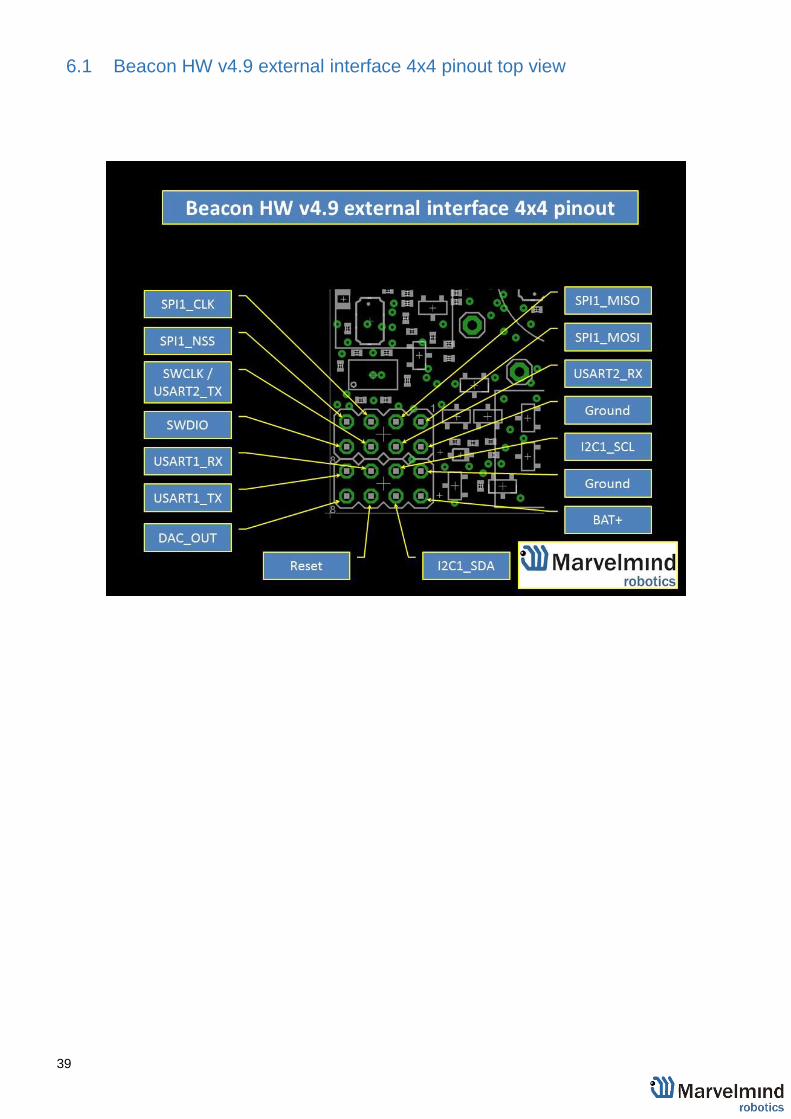
6.1 Beacon HW v4.9 external interface 4x4 pinout top view

40
6.2 Modem HW v4.9 external interface pinout top view

41
7. Advanced system settings and optimization
Start using advanced settings only when you know what you are doing
If you ran into troubles, connect the beacon or modem to the PC via USB and
use the DEFAULT button. It will upload “factory settings” to the board while
keeping the device address untracked
7.1 How to place beacons
Avoid placing beacons on long sound-conducting objects
This is a very rare but may happen in some special circumstances.
The best practice is to place beacons (stationary and mobile) in places that would
not result in the transfer of ultrasound energy from the beacon’s board/case
directly to the place it is attached via a medium other than air. For example, solid
attachment of a beacon to a long horizontal metal tube may result in the following:
• Sound emitted from the beacon propagates directly to the metal tube.
• Propagation losses inside metal are much smaller than in the air
Moreover, the tube may act as a low-loss waveguide.
• If the tube is solid enough and long enough, there may be a weird effect
where the receiving beacon receives the signal sooner than expected,
i.e., sooner than the distance divided by the speed of sound in air. That
happens because the speed of sound in metal is much higher than the
speed of sound in the air. The ultrasound signal may even look stronger
than the real signal propagated through the air due to the lower amount
of losses of ultrasonic in metal than in the air
• It is good practice to place beacons on something relatively soft or
something that does not conduct sound
Place beacons in a way that provides the proper ultrasonic coverage. It
must be one beacon in the line of sight of minimum 2 beacons. Try to locate
them under ceilings to avoid shadows, walls etc.
• Optimal settings for stationary beacons in small and big rooms
Use 30–50 ultrasonic pulses for larger places and the default 5 pulses for
smaller places.
• Optimal settings for noisy environment

42
There are several ways to reduce impact:
Mobile beacons can be placed very close to the source of noise without harm,
but stationary beacons should be placed further from the noise because they are
receiving the ultrasound, whereas the mobile beacon is emitting the ultrasound
7.2 Using Oscilloscope
Monitor ultrasonic signal from one beacon to another
Use Dashboard => View => Oscilloscope to monitor ultrasonic signals from
one beacon to another.
It is a very powerful tool, because it gives also information on the background
noise, level of the signal, echo, etc. With this tool, it is easy to set up the proper
ultrasonic threshold on the Dashboard
Echo
External noises look
similarly.
Thus,
choose the
ultrasonic
threshold
below this
value, for
Type the reference
beacon
number. and
press Enter
Choose the
beacon
to test
Ultrasonic
sign
al

43
7.3 Proper ultrasonic signal detection
When external noise is high:
- Identify the source. Usual suspects:
- Ultrasonic-based volume or movement detection alarm systems
- Other robots using ultrasonic
- Parktronics
- Sources of very strong white or impulse noise (air guns, air press,
cutters, vacuum cleaner, etc.)
- Rotors of drones/copters
Marvelmind Indoor Navigation System uses proprietary 31kHz frequency for
ultrasonic signal and employs additional filtering to combat external noise.
This also makes the system rather immune against the “usual suspects.”
However, if the external noise is too strong, its source is too close, or it’s
emitting a strong signal on frequencies close to 31kHz or white noise, the
system functionality can be affected.
The best things to do in this case are to (1) identify the beacons that are
affected. Usually, they are those that are the closest to the source of noise;
(2) manually reduce the gain of the affected stationary beacons so that the
signal from the mobile beacon would have a 1000–1800 amplitude. That
would give the best signal-to-noise ratio. Don’t make the gain too high. The
noise will be amplified, but the desired signal will be saturated and signal-to-
noise ratio will be poor.
The gain settings may be very non-linear. There is almost no change at 4000
to 3000. But around 2500, the gain starts reducing very quickly (1200 – for
some HW versions). By setting the gain manually, it is possible to find the
optimal gain to obtain the highest signal to noise ratio so the system can work
even in very challenging external conditions.
When the map is formed, only the mobile beacon is emitting, whereas
stationary beacons are not. Thus, it does not matter how close the mobile
beacon is to the source of the noise.
But it matters how close the stationary beacons are to those sources. So select
the positions of the stationary beacons accordingly - place them further from
the sources of noise

44
7.4 Using hedgehog.log file
The system automatically records all measured positions in the hedgehog.log
file that is stored in the same folder as the Dashboard.exe file
The data is written in csv format; each line describes the position of one of the
hedgehogs at a certain moment
The line format is described here
7.5 System accuracy evaluation
1) Accuracy of distances measurement.
Marvelmind navigation system can measure distances between beacons with accuracy of +/- 2cm if it uses correct ultrasound speed in measurements
The ultrasound speed depends of many factors: temperature of air, pressure, humidity and so on
The main factor is temperature. In temperature range of -20…+50 °C the speed
of ultrasound changes on about 0.6 m/ (s* °C). It gives distance error about (0.6
/ 340) *100% ~ 0.17%/ °C. So caused by incorrect temperature setting absolute
error of distance measurement is 0.17% of real distance between beacons. For
example, with distance 30 meters and 5 °C error, this gives 0.85%*30 ~ 0.25
meters’ error. Marvelmind system allows to setup temperature of air in the system
settings
2) Accuracy of position measurement.
Marvelmind system uses trilateration algorithm to calculate position by distances. The inaccuracy of position calculation is related to inaccuracy of distances measurement and to geometry of relative location of stationary and mobile beacons.
Basic trilateration formulas are given in this article: https://en.wikipedia.org/wiki/Trilateration
As you see, the position of mobile beacons X, Y, Z is calculated from positions of 3 stationary beacons which are set by values of d, i, j. One of the beacons was shifted to (0,0) position to simplify formulas in the article. In formulas for X, Y we see d and j in denominators. This means that with low values of d and j small error of this value can cause large position error.
Please see the picture of the beacons in the article - in more simple words, in means that if one of three beacons is close to line connecting other two beacons, it gives increased inaccuracy of locating mobile beacon. For example, assume d= 10, i= 5, j= 0.1, r1= 7, r2= 7, r3= 4.8. We get x= 5, y= 2.4375, z = 4.25. If we suppose that j=0.101 (0.1 cm error), we receive x= 5, y= -0.06, z= 4.89. You see very large Y error. Another example for Z. Assume mobile beacon is relative close to plane of stationary beacons:
d= 8, i= 4, j= 6, r1= 5.02, r2= 5.02, r3= 3.01. This gives X=4, Y= 3.01169, Z= 0.36. If we suppose r3= 3.0 (1 cm error), we receive X=4, Y= 3.016, Z= 0.44. Error on
Z is about 8 cm.
Also, with r1= 5, r2= 5, r3= 3, Z will be 0. As you see, low change of distances
causes large change of Z value near the plane
45
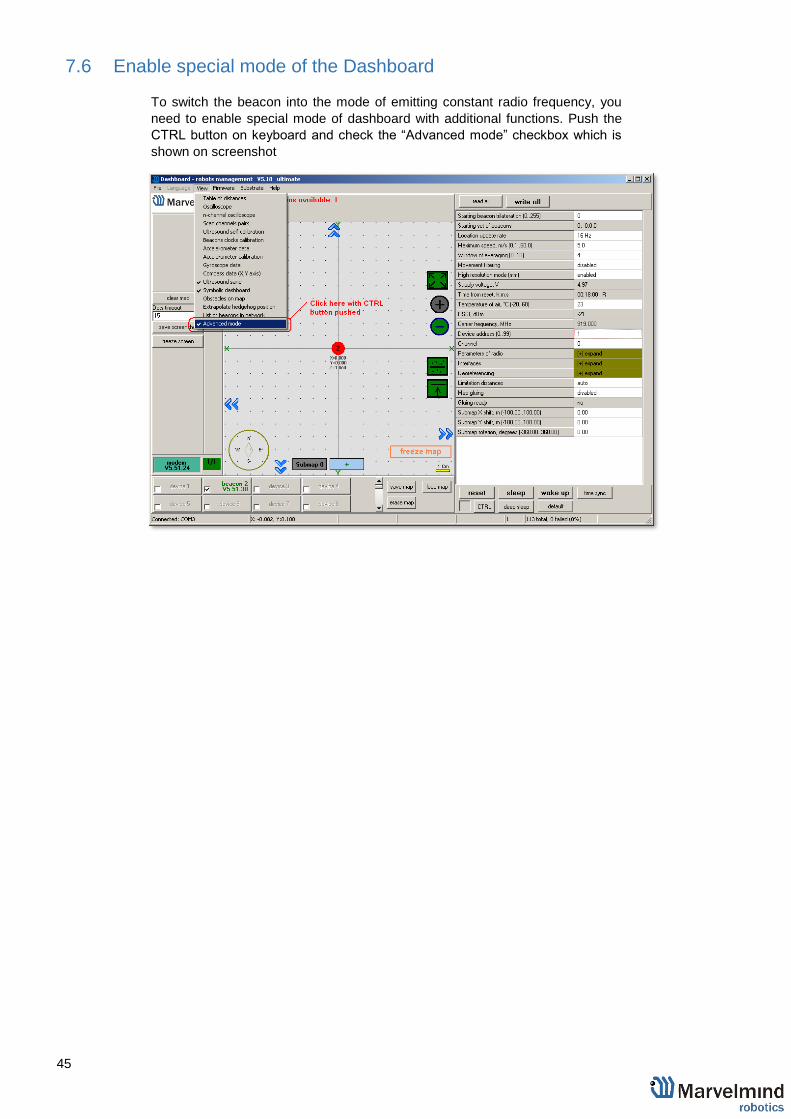
7.6 Enable special mode of the Dashboard
To switch the beacon into the mode of emitting constant radio frequency, you
need to enable special mode of dashboard with additional functions. Push the
CTRL button on keyboard and check the “Advanced mode” checkbox which is
shown on screenshot

46
7.7 Force the beacon to emit radio frequency
Click on the button with the beacon on bottom of the window (“beacon 2” in this
example) and enter the frequency of emission as shown on following screenshot
After this, the beacon starts permanent emission of selected frequency
Communication with modem will be lost, and after some time the beacon will
disappear in dashboard
To return communication with beacon, press hardware reset button on the
beacon
After reset, the beacon may restart emission on the same frequency because it
was entered in dashboard.
If you need to change frequency of emission, repeat this instruction starting from
section 2, or enter another frequency value in window shown on last screenshot
and then make the hardware reset of the beacon

47
7.8 Settings to obtain correct north direction
In some cases, it is necessary to obtain a correct north orientation of the map for
NMEA output from Marvelmind system. For example, when using a Marvelmind
mobile beacon as the navigation data source for Pixhawk installed on a copter,
correct north is required for correct yaw control of the copter. The Marvelmind
system cannot determine north automatically, so the user should make
corrections after building and freezing the map. It can be done in one of two ways:
7. Rotate the Marvelmind map using the dashboard, as shown on
the attached screenshot.
8. You can also view the video:
https://www.youtube.com/watch?v=AsYXrtg7aVU&feature=youtu.be
Enter the angle correction (the angle shown on screenshot) on the Pixhawk side
from the Mission Planner of APM Planner.
Refer to the parameter "BCN_ORIENT_YAW":
http://ardupilot.org/copter/docs/parameters.html?highlight=bcn_orient_yaw
Beacons may issue raw sensor data. To learn how to obtain this data, please
check this protocol:
https://drive.google.com/open?id=0ByNFYpty-t_CRWxSWmhKTkkzVzg
See section 1.3. The data output comes from UART and the USB (virtual UART)
on the mobile beacon.
You can receive the data byte-by-byte and check for the required packet header
See an example here:
http://www.marvelmind.com/downloads/2017_02_08_C_example.zip

48
7.9 Communication of Pixhawk with Marvelmind mobile beacon
The Marvelmind mobile beacon can be connected to Pixhawk (and to any other
hardware or software that inputs GPS according to the NMEA0183 protocol).
The mobile beacon can send GPS data via UART and USB (virtual UART)
interfaces. For further explanation, please check out this document

49
7.10 Sending path to robot
1. The dashboard sends request to modem via USB.
Procedure of sending these requests in dashboard is shown on second
screenshot.
This format of request is described in section 8 of modem protocol:
https://marvelmind.com/wp-content/uploads/2017/08/modem_usb_protocol_2017_01_27.pdf
2. modem transmits data to the hedgehog via radio, using our proprietary protocol

50
3. the hedgehog communicates with robot via UART. Hegehog sends data according to
section 2.3.1 of this protocol:
https://www.marvelmind.com/pics/marvelmind_beacon_interfaces_v2017_09_13.pdf
The robot should confirm receiving data by response packet shown in section
2.3
This communication on the robot side is implemented in the Arduino example on
our site. As you can see in the protocol, robot should not request the waypoints,
the hedgehog will send the waypoints when they will be transmitted from
dashboard. But robot should confirm receiving each waypoint by this packet:
[0x03,0x47,0x01,0x02,0x00, <2 bytes of checksum>]

51
7.11 Proper ultrasonic coverage
The single most important requirement for the system to work well is to have
proper ultrasonic coverage
Each sensor has an ultrasonic beam of ~90 degrees. Outside of that range, the
emitting power and sensitivity drops quite rapidly. From the left, right, or back of
the ultrasonic sensor, the signal is highly attenuated. Thus, it is crucial to provide
proper ultrasonic coverage for the area where the robot will be moving.
- It is also very important to provide proper ultrasonic coverage to the stationary
beacons when the map is being formed.
Mobile beacon (“hedgehog” or “hedge”) is designed to be placed
horizontally
- The mobile beacon has four horizontal and one vertical sensor, each covering its
own sector. Together, they cover 360 degrees horizontally and 180 degrees in the
upper hemisphere. The lower hemisphere is highly attenuated, so don’t expect
ultrasonic coverage in that area.
It is advised that the mobile beacon be placed as high as possible on the robot if
the stationary beacons are above the mobile beacon. This minimizes shadows
from other objects, people, etc.

52
- Example of proper positioning of the mobile beacon can be found here:
https://youtu.be/PFgNPkLGCDk.
The beacon is placed horizontally and above other objects that can cast a shadow
on the stationary beacons
Keep the radio signal’s strength under control
- The RSSI (Dashboard => right menu) of any beacon/modem must not be higher
than -25dBm. Otherwise, the system may malfunction.
It is recommended the distance between the modem and beacons be no less than
0.5–1m. Beacons can be placed as close to each other as needed. If a beacon is
extremely close to the modem, disconnect the antenna from the beacon. Monitor
the Received Signal Strength Indicator (RSSI). It must be in the range of -25 to -
70dBm. An RSSI of less than -70dBm will work too, but packet losses may start
occurring. The quality of the radio connection very much depends on external
interference as well because the used band is ISM (either 915MHz or 433MHz)
and there are numerous co-existing systems

53
Use 30 - 50 periods (pulses) in settings instead of the default 5. Select:
Ultrasound settings => Number of periods
When you have large errors in position estimation (more than a 1m inaccuracy),
use the embedded Oscilloscope on Dashboard => View to determine which
stationary beacon is jammed
Reduce the gain of the ultrasonic manually depending on your system
• Multibyte numbers are transmitted starting from low byte (little endian format)
Negative values represented as two's complement
For example:
a 32-bit integer value '-100' is represented as FFFFFF9C
(transmitted as sequence 9C, FF, FF, FF in little endian format)
This value is detected as negative by '1' value of MSB
and converted by subtracting 2^32: 0xFFFFFF9C- 0x100000000 = -0x64= -100

54
7.12 Sensors settings: example for 2D and mobile beacon
Beacon 2
Beacon 3
2D
Hedgehog 7
Beacon 2
RX1 and RX4 emit ultrasound in normal mode for better ultrasonic signal exchange with Beacon 3. In frozen mode RX2 added as working sensor. The rest sensors are turned off Changing sensors’ settings could be found in
the panel in the upper right corner of the
Dashboard during your beacon is connected to
the computer
Beacon 3
RX3 and RX4 emit ultrasound in
normal mode for better
ultrasonic signal exchange
with Beacon 2. In frozen
mode RX2 added as
working sensor. The rest
sensors are turned off

55
7.13 Powering beacons
Modes of operations
1. Stationary beacons powered from a clean source of +5V USB
2. Mobile beacon powered from a clean source of +5V USB from a robot
3. Operations based on internal LiPol 3.7V 1000 mAh cell
- Typical power consumption in deep sleep mode is 50uA, which provides ~2 years
of shelf time with a regular 1000mAh battery. The beacon can be woken up from
deep sleep only by pressing HW RESET button
- In regular sleep mode, the beacons wake up automatically every 2 seconds for
~20ms to monitor external calls from the modem/router. That causes some
additional consumption, but it can still be left for several months in sleep mode
- Active mode work time directly depends on the location update rate. For example:
o With the standard 1000mAh battery and 16Hz update rate, the
expected work time will be 97h => 8 days (assuming a 12-hour
working day).
With the extended 4300mAh battery and 1Hz location update rate, the expected work time
will be ~5800h or 484 days (assuming a 12-hour working day)

56
8. Frequently Asked Questions 8.
Please check this forum for more information. Here we will answer the most
common questions
1 What is the proper way to place the beacons?
The actual distance between beacons must be ≤ 30 m. Provide the line
of sight from one beacon to minimum two others
2 How far can beacons be located from modem?
In the open space the distance from the modem to the beacon can reach
several hundred kilometers
3 What if hedgehog shown as orange circle or inside
in the Dashboard?
In the open space the distance from the modem to the beacon can reach
several hundred kilometers
4 What is the obstacle for ultrasound?
The real obstacles for ultrasound are walls (concrete), glass, metal. If
you need to cover a multiple-floor territory you can use our Submap
feature in which case the tracking will not be interrupted
5 How the system works in very low and very high temperatures?
The optimal conditions for the system is 0 ºС - 40 ºС
6 Are beacons resistant to explosions, dust, dirt, water, noise?
- Low-frequency noise (motor noise, industrial equipment) does not
interfere with the normal operation of the system
- We now working on IP67 version of beacon. It can work underwater at
a depth of one meter up to half an hour. It will be fully resistant to dust,
t will have protected housing and sensors
7 Is ultrasound harmful for human
We are surrounded by ultrasound impact. For example: parktronic,
automatic doors, security alarms. Ultrasound is not harmful as you
used to think
8 What is the time of delay between positioning the object and
respond?
The delay is directly proportional to the update rate. For example, if
update rate is 16 Hz delay is 60 ms

57
9 What if losing hedgehog after 0.6 m
By default, the service area for mobile beacons is limited and mobile
beacon not positioning far from stationary beacons.
The limit is 1.5x times the maximum distance between the stationary
beacons. To expand the service area, please follow the instructions
shown in the attached screenshot. Notice that positioning the mobile
beacon far from stationary beacons and close to their plane may result
in increased positioning error because of bad geometry of
measurement
Top Related