


Languages
Pages
Legal


User Manual
1
Inclined Digital Inclinometer System User Manual
Man191
4.2.0
07/08/2014
L Williams T Millward
C Rasmussen
Phil Day P Royle
Chris
Rasmussen
Manual No.
Revision
Date
Originator
Checked
Authorised for
Issue
User Manual
2
Contents
Section 1 : Introduction ................................................................................................................................. 3
Section 2 : Equipment Supplied .................................................................................................................. 4
2.01 The Cable Reel and Probe ............................................................................................................ 4 2.02 The Digital Readout (Field PC) and Accessories ..................................................................... 4 2.03 Remote Handheld Activator (Key Fob) ..................................................................................... 4 2.04 Specifications ................................................................................................................................. 4 2.05 Before First Use .............................................................................................................................. 4
Section 3 : About ‘In-Port’ Software ........................................................................................................ 5
3.01 Purpose ............................................................................................................................................ 5 3.02 System requirements ................................................................................................................... 5 3.03 Interacting with the system ........................................................................................................ 5 3.04 Finding your way around ............................................................................................................. 5 3.05 The Virtual Keyboard .................................................................................................................... 5 3.06 Help – I’m Lost! ............................................................................................................................. 6 3.07 Installing In-port from the memory card ................................................................................. 6
Section 4 : ‘In-Port’ Software ...................................................................................................................... 8
4.01 Basic concept of operation........................................................................................................... 8 4.02 Setting Up Bluetooth on the Field PC ........................................................................................ 8 4.03 Admin and User Modes ................................................................................................................. 9 4.04 Starting the program .................................................................................................................. 10 4.05 Start up screen ............................................................................................................................ 10 4.06 Admin screen 1 – Site Set-up ................................................................................................... 10 4.07 FormSet2 – Borehole Set-up .................................................................................................... 11 4.08 To amend or delete existing boreholes ................................................................................... 11 4.09 To add boreholes to a site:........................................................................................................ 12 4.10 To amend or delete existing boreholes ................................................................................... 12 4.11 User Screen 1 (FormUse1) ........................................................................................................ 12 4.12 FormUse2 – Readings ................................................................................................................. 13 4.13 Comparison of Last Two Reading Sets .................................................................................... 15 4.14 Download Readings screen ........................................................................................................ 16 4.15 Transferring Downloaded Files to a PC ................................................................................... 17 4.16 Register key fob ........................................................................................................................... 17
Section 5 : Operating Procedure .............................................................................................................. 19
5.01 Introduction & Reading Overview ............................................................................................ 19 5.02 Checking the Equipment Before Use ....................................................................................... 19 5.03 Taking Readings .......................................................................................................................... 19
Section 6 : Maintenance ............................................................................................................................... 21
6.01 Care And Maintenance Of The Inclinometer System ........................................................... 21 6.02 Charging The System ................................................................................................................. 21 6.03 Field PC Battery Life .................................................................................................................... 23 6.04 Calibration ..................................................................................................................................... 24 6.05 Troubleshooting ........................................................................................................................... 25
Appendix A. CE Declaration ........................................................................................................................ 26
User Manual
3
Section 1 : Introduction
The Soil Instruments Inclined Digital Bluetooth Inclinometer System is designed and built using the latest technology.
The readings are acquired and displayed using ‘In-Port’ Soil Instruments Field PC based software. Bluetooth technology and the remote handheld activator (Key Fob) are used for taking readings.
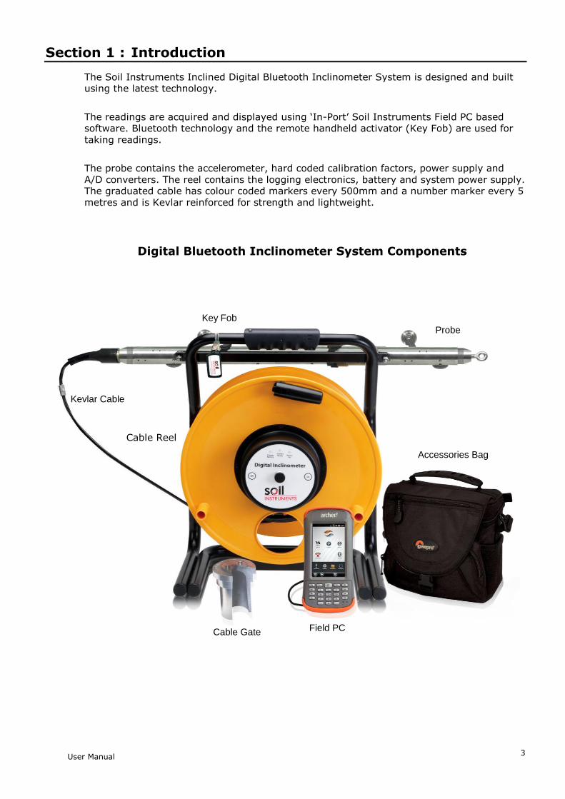
The probe contains the accelerometer, hard coded calibration factors, power supply and A/D converters. The reel contains the logging electronics, battery and system power supply. The graduated cable has colour coded markers every 500mm and a number marker every 5 metres and is Kevlar reinforced for strength and lightweight.
Digital Bluetooth Inclinometer System Components
Key Fob
Field PC
Cable Reel
Probe
Kevlar Cable
Cable Gate
Accessories Bag
User Manual
4
Section 2 : Equipment Supplied
Cable Reel and Accessories (charger and leads)
Uniaxial Inclinometer Probe with connector to attach cable
Shock resistant and water proof Rugged Digital Readout (Field PC) and Accessories case
Remote Handheld Activator (Key Fob)
2.01 The Cable Reel and Probe
The cable reel contains a charging socket in the centre of the reel. The Uniaxial Inclined Inclinometer Probe is attached to the cable with a strong durable waterproof plug and socket arrangement. (Always ensure this is fully hand tightened before taking readings)
2.02 The Digital Readout (Field PC) and Accessories
The Field PC communicates to and from the reel by means of Bluetooth technology and so requires no leads or cables. It is supplied with a lead for downloading to a PC or laptop via a USB connection, a charger is also supplied. The Field PC comes with Soil Instruments ‘In-Port’ and Microsoft Active Sync software already installed.
2.03 Remote Handheld Activator (Key Fob)
The Key fob comes with a sprung clip for attaching to the Field PC case or elsewhere. It enables the user to take readings without having to touch the Field PC screen. If preferred, readings can be taken using the ‘read’ button on the Field PC, the key fob, or a combination of both to suit personal preference.
2.04 Specifications
Please refer to the datasheet for the current specification for the particular instrument delivered. If in doubt please contact Soil Instruments.
2.05 Before First Use
IMPORTANT If the Field PC has not been used for a prolonged period of time; it may loose battery power and also may then loose its ‘In-Port’ installation. The Field PC is designed to retain programs even if the battery is allowed to fully discharge, however we recommend that the battery is charged on a regular basis and that the reel and Field PC are allowed to fully charge before the system is first used.

User Manual
5
Section 3 : About ‘In-Port’ Software
3.01 Purpose
‘In-Port’ is a program to take readings from our digital Inclinometers. It uses Bluetooth wireless technology to communicate with the Inclinometer, receive the readings, perform checksums and store the results. In_port also hold details of active boreholes, allows for new boreholes to be set up and prompts the user through the reading process.
3.02 System requirements
‘In-Port’ will run on any Personal Digital Assistant (Field PC), which runs the Microsoft Pocket PC operating system, version 2003 or higher. It does not need any of the programmable buttons on the Field PC to function, but any one of these buttons can be programmed to start up the software – see your Field PC’s user manual for details. It has a footprint of approximately 124Kb and uses about 3.5Mb of memory when running. In addition, the database it uses has an initial footprint of approximately 250Kb; this will slowly grow as readings are taken, but should never exceed 1 or 2 MB, provided readings are regularly downloaded and deleted.
3.03 Interacting with the system
There are three user modes within the ‘In-Port’ software, two for controlling and entering data into the program and one for direct communication with the probe reel to take readings. For using the program we have:
The stylus. This is situated in its holder at the top of the Field PC. Deliver a brief, firm tap with this at the appropriate point on the screen to press a button, change the value of a check box, etc, or to place the cursor in order to enter text. Text is entered using
The virtual keyboard. See section 4.06 below for more detail on this.
The Key Fob. For direct communication with the probe reel there is the Key Fob. This is a button-activated radio transmitter that tells the probe to take a reading and send the data to ‘In-Port’ software. A momentary press on the button operates the Key Fob. It does not need to be pointed at the probe directly, but will work better when it is. It is not very effective when solid objects such as walls intervene.
3.04 Finding your way around
When the system is started for the first time, or after a soft reset of the Field PC, the Today screen will be displayed. To access the ‘In-Port’ software, tap on the Start button at the top left to drop down the Programs menu. In here you will see ‘In-Port’. Tap this to start the program. When a program is running, tap the same place (where the name of the current program or form appears), or on the Windows icon in the very top left-hand corner, to drop down the programs menu.
In the bottom right of the Today screen will be the Bluetooth icon. Tap on this and select Turn Bluetooth On/Off as needed.
For other functions not specific to ‘In-Port’, see the built-in help or the Field PC user manual.
When ‘In-Port’ is running, actions will be selected either from buttons on screen or from the menu bar at the bottom of each screen.
3.05 The Virtual Keyboard
This is a software equivalent of a keyboard. It is displayed or hidden by tapping the keyboard icon in the bottom right of the screen (this is only visible when a program is running that can use the keyboard for input). To use it, simply tap the required key. Tap the Shift button for a single upper-case letter or special character, or tap on CAP for continuous entering of shifted characters. More special characters, especially accented letters, are available by tapping the “áü” key.
User Manual
6
Before starting to use the virtual keyboard, ensure the cursor is positioned at the point where you need the text to appear (by tapping that point on the screen).
3.06 Help – I’m Lost!
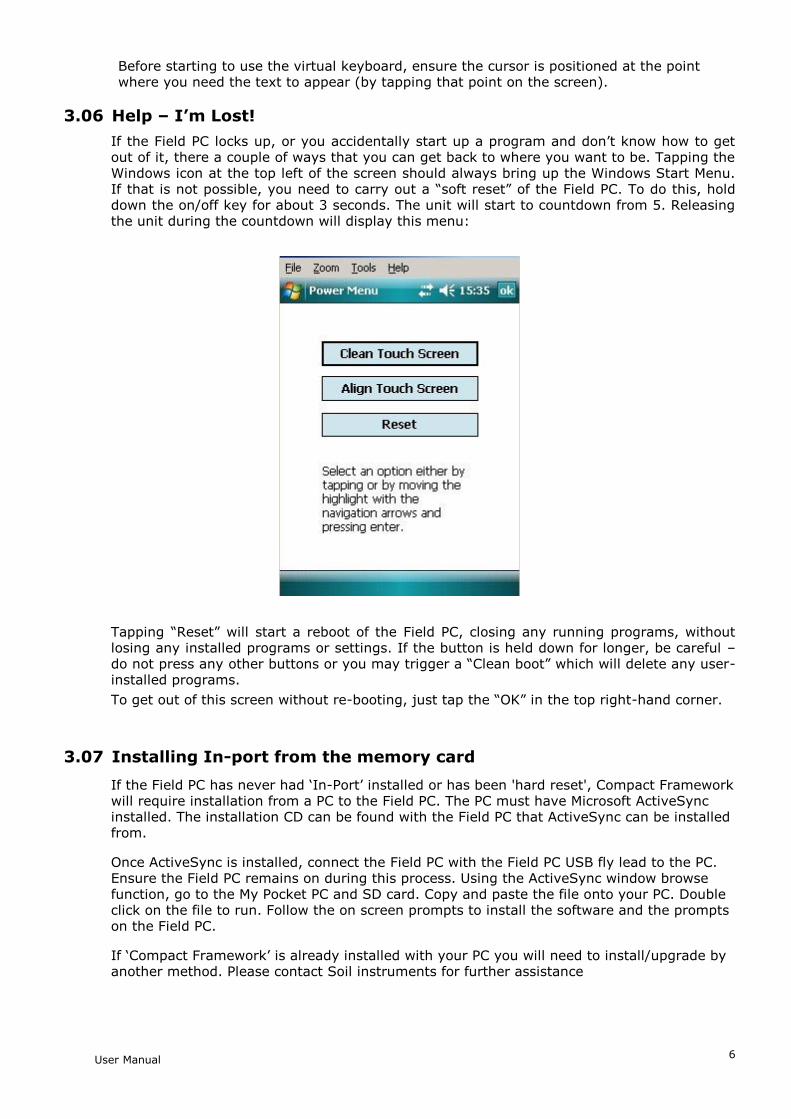
If the Field PC locks up, or you accidentally start up a program and don’t know how to get out of it, there a couple of ways that you can get back to where you want to be. Tapping the Windows icon at the top left of the screen should always bring up the Windows Start Menu. If that is not possible, you need to carry out a “soft reset” of the Field PC. To do this, hold down the on/off key for about 3 seconds. The unit will start to countdown from 5. Releasing the unit during the countdown will display this menu:
Tapping “Reset” will start a reboot of the Field PC, closing any running programs, without losing any installed programs or settings. If the button is held down for longer, be careful – do not press any other buttons or you may trigger a “Clean boot” which will delete any user-installed programs.
To get out of this screen without re-booting, just tap the “OK” in the top right-hand corner.
3.07 Installing In-port from the memory card
If the Field PC has never had ‘In-Port’ installed or has been 'hard reset', Compact Framework will require installation from a PC to the Field PC. The PC must have Microsoft ActiveSync installed. The installation CD can be found with the Field PC that ActiveSync can be installed from.
Once ActiveSync is installed, connect the Field PC with the Field PC USB fly lead to the PC. Ensure the Field PC remains on during this process. Using the ActiveSync window browse function, go to the My Pocket PC and SD card. Copy and paste the file onto your PC. Double click on the file to run. Follow the on screen prompts to install the software and the prompts on the Field PC.
If ‘Compact Framework’ is already installed with your PC you will need to install/upgrade by another method. Please contact Soil instruments for further assistance
User Manual
7
If the ‘In-Port’ program is lost for any reason (in other words, does not appear in either the “Start” menu or the “Programs” screen), it must be re-installed from the supplied memory (Storage Card) card. Use the File Explorer program to navigate to the card, as follows:
tap on “Programs” in the Start menu, then on “File Explorer”
from the top left-hand drop-down menu, choose “My Device”. If this is not visible, click on the first item in the drop-down list and repeat this until “My Device” is visible.
click on “Storage Card”
two programs must be installed. To install, just click on the name once, and wait until installation is complete. The following programs must be installed, in the order shown. If any one of them says it already exists, just say yes when asked if it is OK to overwrite it.
1. sqlce30.ppc.wce4.armv4.cab
2. In_port.cab
(There should be a message saying, “re-installing ‘In-Port’ will overwrite any existing database, so the database should be copied elsewhere before re-installing. It can be found in the “Storage Card” folder, and is called “DB_Inport2.sdf”.)
When prompted, install the files onto the ‘Device’ not the ‘SD’ card.
The program will now be in the “Program Files” screen, but probably not in the Start menu, as the Field PC will have returned to its factory settings and the limit on the number of programs in the menu will have been reached. To rectify this, Tap on Start – Settings. On the “Personal” tab, select “Menus”. By checking and unchecking options, you will be able to customise the Start menu.
Note: On some Field PC’s a warning may be generated when installing any of the above, saying the program may not display correctly as it was designed for a previous version of Windows Mobile Software. This message can be safely ignored.
IMPORTANT INFORMATION
We strongly recommend that you back up the information from the Field PC storage card on a regular basis to prevent loss of data and software due to
accidental deletion by users.
Although the software can be re-installed, the database and information created by users can not be recovered if accidentally deleted.

User Manual
8
Section 4 : ‘In-Port’ Software
4.01 Basic concept of operation
‘In-Port’ is the set-up and borehole logging software for the Soil Instruments range of Digital Inclinometers. The same program can be used to read Vertical, Horizontal or Inclined inclinometers. A mix of differently oriented boreholes can even be defined for the same site. It uses Bluetooth wireless technology to take and receive readings from an inclinometer, and saves those readings to a database. They can then be downloaded to a text-format file, which can then be transferred to a PC, using Microsoft’s ActiveSync software, for later loading into In-Site analysis software. To use ‘In-Port’ to read an inclinometer, the site and its boreholes must have been defined, using the “Admin” mode. The typical model of use is:
i. Define the site
ii. Define all boreholes
iii. Take readings
iv. Download readings for a site and, optionally, delete them
v. Transfer readings to PC and process using software such as In-Site
Steps (i) and (ii) are done only once for each site. Steps (iii) to (v) will be carried out each time readings are taken, although steps (iv) and (v) can be delayed – in other words, repeated sets of readings can be taken before downloading them.
More detailed information on these procedures will be found in the following sections.
IMPORTANT it is essential that the “local settings” for both Field PC and PC are the same – ie they are both set to “English (UK)”, “English (United States)”, “French”, etc. Also, it is not advisable to switch the Field PC from one locale to another when readings are in the database. Delete any existing readings before changing local settings.
4.02 Setting Up Bluetooth on the Field PC
The Field PC and reel are shipped fully set-up and ready for use. If for some reason Bluetooth does not start when ‘In-Port’ is run (the blue ‘comms ready’ light on the reel should be illuminated), follow the procedure below to re-connect to the reel via Bluetooth when ‘In-Port’ is started.
Note: Exit ‘In-Port’ before following these instructions
Ensure the reel and the Field PC are switched on and within 1.5 metres of one another.
From the start menu screen tap the small Bluetooth Icon at the bottom right of the screen:
or, from the ‘Start’ menu, select ‘Settings’ then the ‘Connections’ tab at the bottom of the screen, then tap on the Bluetooth icon that will then be seen.
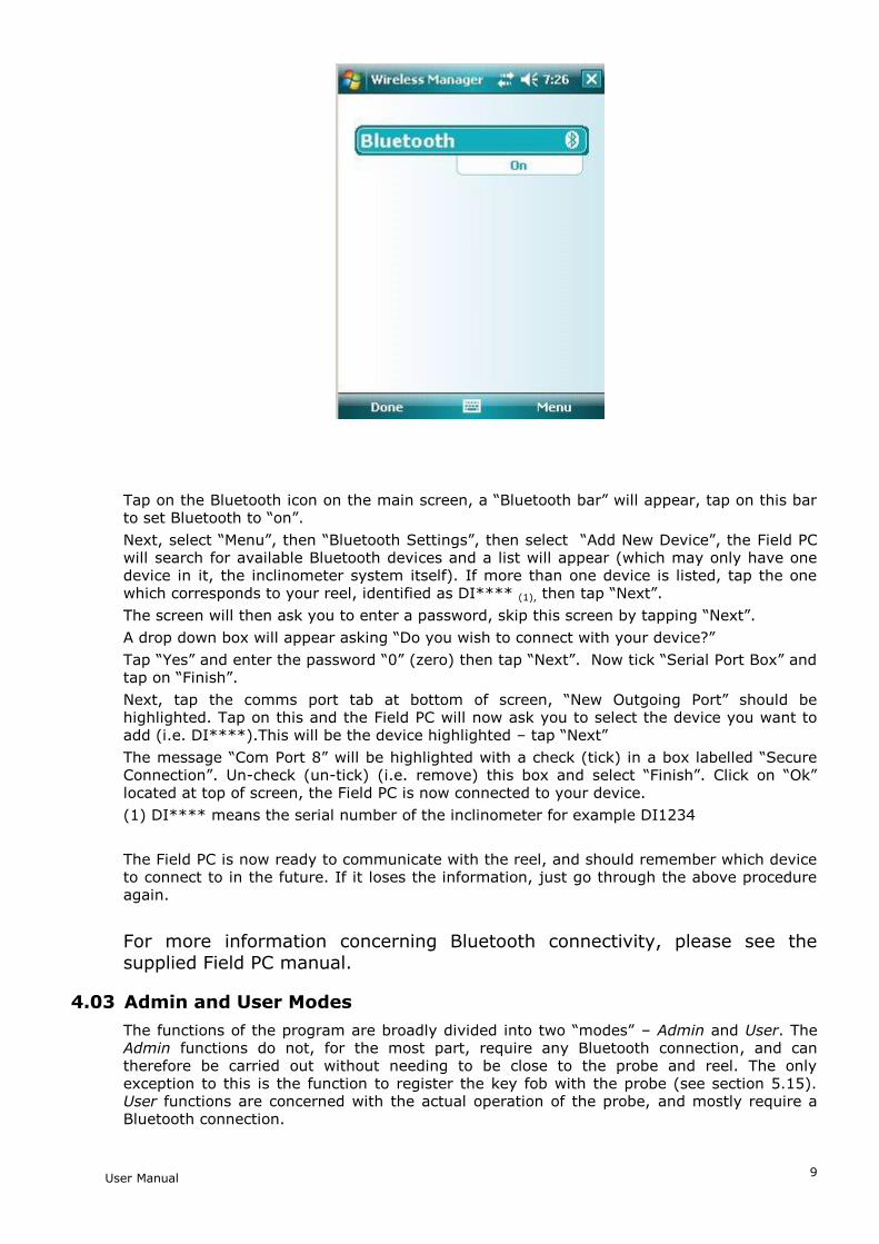
Once the icon above has been tapped the initial Bluetooth screen will appear:
User Manual
9
Tap on the Bluetooth icon on the main screen, a “Bluetooth bar” will appear, tap on this bar to set Bluetooth to “on”.
Next, select “Menu”, then “Bluetooth Settings”, then select “Add New Device”, the Field PC will search for available Bluetooth devices and a list will appear (which may only have one device in it, the inclinometer system itself). If more than one device is listed, tap the one which corresponds to your reel, identified as DI**** (1), then tap “Next”.
The screen will then ask you to enter a password, skip this screen by tapping “Next”.
A drop down box will appear asking “Do you wish to connect with your device?”
Tap “Yes” and enter the password “0” (zero) then tap “Next”. Now tick “Serial Port Box” and tap on “Finish”.
Next, tap the comms port tab at bottom of screen, “New Outgoing Port” should be highlighted. Tap on this and the Field PC will now ask you to select the device you want to add (i.e. DI****).This will be the device highlighted – tap “Next”
The message “Com Port 8” will be highlighted with a check (tick) in a box labelled “Secure Connection”. Un-check (un-tick) (i.e. remove) this box and select “Finish”. Click on “Ok” located at top of screen, the Field PC is now connected to your device.
(1) DI**** means the serial number of the inclinometer for example DI1234
The Field PC is now ready to communicate with the reel, and should remember which device to connect to in the future. If it loses the information, just go through the above procedure again.
For more information concerning Bluetooth connectivity, please see the supplied Field PC manual.
4.03 Admin and User Modes
The functions of the program are broadly divided into two “modes” – Admin and User. The Admin functions do not, for the most part, require any Bluetooth connection, and can therefore be carried out without needing to be close to the probe and reel. The only exception to this is the function to register the key fob with the probe (see section 5.15). User functions are concerned with the actual operation of the probe, and mostly require a Bluetooth connection.
User Manual
10
4.04 Starting the program
Ensure the reel is turned on if you are planning to enter ‘User Mode’. When the program is started, Bluetooth is automatically turned on when entering ‘User Mode’. This is confirmed by the blue ‘comms ready’ light on the reel. If Bluetooth does not start see section 5.02 to re-set the connection (it will then be automatic).
To start In_Port, tap the stylus on the word “Start” at the top left of the screen (or the Windows icon in the very top left corner). A menu of available programs will drop down. Tap on “In_port”.
Note: it is possible, under certain circumstances, that the program may not appear in the Start menu. If so, it may still be under Start – Programs. If it is here, you can get it into the menu by using Start – Settings – Personal – Menus as described at the end of section 4.07.
If it is not here either, it must be fully re-installed as in section 4.07 above.
4.05 Start up screen
Here, the user is given the choice of which mode to work in, either by tapping the appropriate radio button and then “GO”, or by choosing a mode from the “Mode” menu. As stated above, if “User” mode is chosen ensure the reel is switched on first and that approx 7-10 seconds after ‘Enter Use Mode’ has been selected and ‘Go’ pressed, that the ‘comms ready’ blue light on the reel illuminates.
If “Admin” is selected, the user is presented with FormSet1 – Site set-up. If “User” is chosen, the default screen that appears is User screen 1.
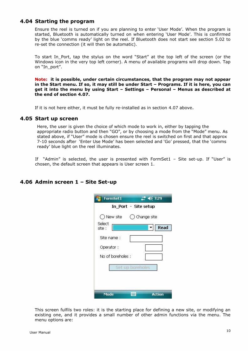
4.06 Admin screen 1 – Site Set-up
This screen fulfils two roles: it is the starting place for defining a new site, or modifying an existing one, and it provides a small number of other admin functions via the menu. The menu options are:
User Manual
11
Action | Exit - exit program
Action | Register key fob with reel - see section 5.16
Action | Start again - new probe – this returns to the Start-up screen, after closing any open Bluetooth connection (This command is available on all screens and is , effectively, also the way to change from one mode to another)
Action | Download Readings – See section 5.13
The user is initially presented with two choices:
New Site
Change Site
If (a) is selected, the radio buttons are hidden and a new field appears, “6-character site code”. This code can be up to 6 alphanumeric characters – which should be unique, meaningful and easily remembered. The rest of the fields can then be filled in: enter a site name, 3-character Operator Id and the number of boreholes this site will have (this can be amended later, if necessary).
When (b) is selected, a drop-down box of the available sites will appear. Select the desired one of these and tap “Read”. The site’s details will be shown.
In either case, to go on to amend the site further or to continue to set it up, tap on “Set-up Boreholes”. This will then display FormSet2:
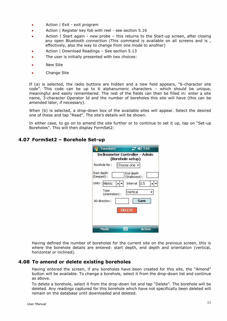
4.07 FormSet2 – Borehole Set-up
Having defined the number of boreholes for the current site on the previous screen, this is where the borehole details are entered: start depth, end depth and orientation (vertical, horizontal or inclined).
4.08 To amend or delete existing boreholes
Having entered the screen, if any boreholes have been created for this site, the “Amend” button will be available. To change a borehole, select it from the drop-down list and continue as above.
To delete a borehole, select it from the drop-down list and tap “Delete”. The borehole will be deleted. Any readings captured for this borehole which have not specifically been deleted will remain on the database until downloaded and deleted.
User Manual
12
NOTE: Once a borehole has been created, it should not thereafter be renamed, or any
readings associated with it in the database will be lost.
4.09 To add boreholes to a site:
Enter a borehole number in the top box (although these are traditionally referred to as “borehole numbers” they can in fact be alphanumeric – up to a total of 6 characters).
Enter Start Depth (the point at which the inclinometer readings will begin – i.e. the lowest point of the hole) and End Depth (the top of the hole).
Select the Units of measurement for this borehole – English or Metric. (Note: English only applies to vertical inclinometers where the probe gauge length is 24 inches. Inclined and horizontal inclinometers are always 500mm probe gauge length and therefore Metric must always be selected with these).
NOTE: this only affects the options available for the Interval data wheel. The setting of “Units” is NOT used when taking readings – it is taken from the calibration data stored in the probe, as it is inseparably connected with the probe length.
Select the Interval between reading points.
The software is designed for all three types of inclinometer: Vertical, Inclined and Horizontal. Choose the correct type from the drop-down list.
Enter a 3-character code for the A0 direction. This code will always appear in any drop-down list of boreholes, as a reminder to the user of how the probe should be oriented in the hole.
Tap “Save”
At this point, the “Amend” button will be enabled. If you want to go back and amend a borehole, tap “Amend” and the “Borehole No” text box will change to a drop-down list of existing holes. Tap one to select it, make any changes and tap “Save”. The changes will be saved and the text box will once more be ready for the next new borehole.
When all the holes specified in the previous screen have been defined, a message to that effect will be displayed. The “Amend” button will now be disabled, as amending (or deleting, via the “Delete” button) are now the only options. To amend a hole now, just select it from the drop-down list and continue as above.
4.10 To amend or delete existing boreholes
Having entered the screen, if any boreholes have been created for this site, the “Amend” button will be available. To change a borehole, select it from the drop-down list and continue as above.
To delete a borehole, select it from the drop-down list and tap “Delete”. The borehole will be deleted. Any readings captured for this borehole which have not specifically been deleted will remain on the database until downloaded and deleted.
NOTE: Once a borehole has been created, it should not thereafter be renamed, or any readings associated with it in the database will be lost.
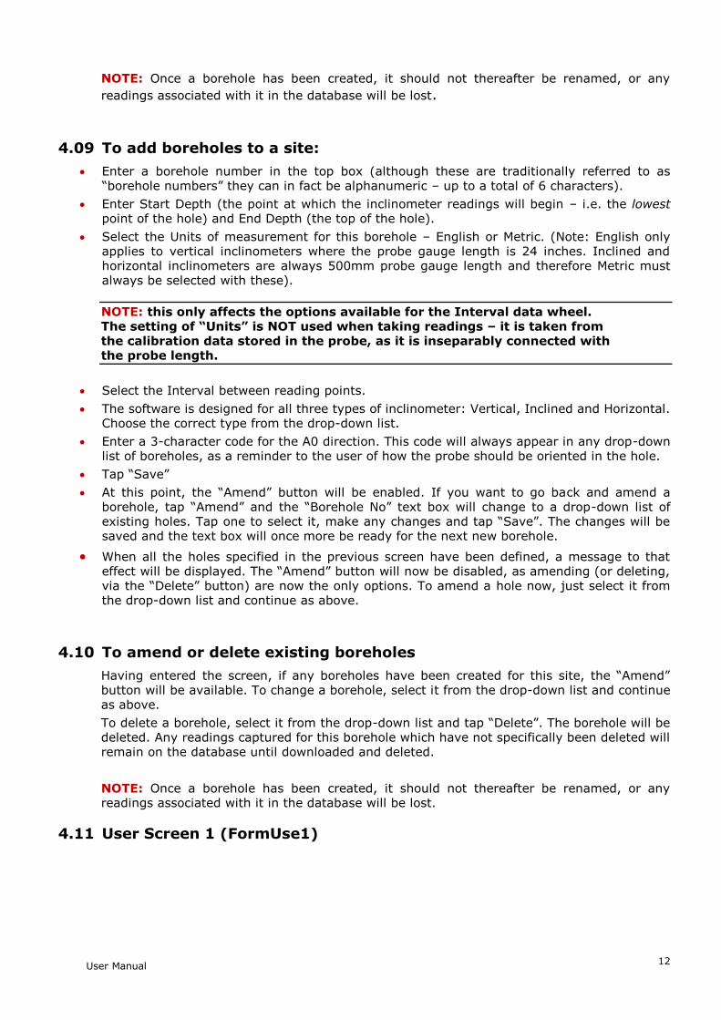
4.11 User Screen 1 (FormUse1)
User Manual
13
IMPORTANT: before selecting this screen, ensure that Bluetooth is switched on (i.e. the blue ‘comms ready’ light on the reel is illuminated)
This is where the user chooses the site to be read. From the drop-down box of site names, one is selected. A three-character Operator Id can be entered if desired. If this is left blank, the Operator ID specified in the Site Setup screen will be used (the Operator ID appears in the downloaded data files). Tapping on “Get Readings” will take the user to the second User screen, where the actual readings are taken.
There is also the option here to enable the program’s stabilisation check. This, when a borehole is selected will wait 90 seconds, then cause repeated readings to be taken 30 seconds apart, until two successive readings are within 0.02 mm of each other. The program will not continue until this condition is met. It will also carry out the same test on the repeat run with the probe rotated 180º. To omit this check, clear the box, this is checked by default.
When this screen is first entered, the Field PC will interrogate the reel and retrieve the probe calibration data from it, to apply to the readings. If there is any problem with this step, the “Get Readings” button will not be available. If the problem is with the data returned from the reel, an appropriate error message will be displayed. Please refer to the ‘troubleshooting’ section at the end of this manual for advice should this happen.
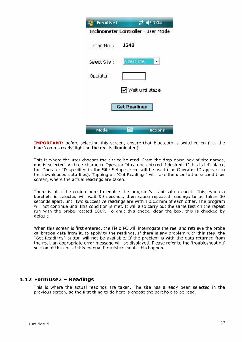
4.12 FormUse2 – Readings
This is where the actual readings are taken. The site has already been selected in the previous screen, so the first thing to do here is choose the borehole to be read.
User Manual
14
Note: for Horizontal and Inclined inclinometers, the “B Rdng” box will not
be shown.
Select a borehole from the drop-down list. The start depth will be displayed. The direction will initially be shown as “A0”.
Incomplete reading sets
At this stage, if a previous set of readings for this borehole was not completed, the program will invite the user to carry on from the point where the readings were interrupted. If they say “No” to this, the partial set of readings will be lost, and it will be necessary to start again, taking a full set of readings.
To take a reading, position the inclinometer to the correct depth and either press the key fob or tap the “Read” button. The reel will sound a single beep to indicate it has received the read request. The probe will take a number of readings and return the maximum and minimum values, which will be averaged and displayed. If the difference between the two values is greater than a pre-determined value, an error message will be displayed, indicating that the probe was not stable in the borehole. In this case, the user is given the option of repeating the reading or accepting it as it is.
If the reading is valid, the readings in the A and B directions (or just A, as appropriate) will briefly be displayed. After 2 seconds, there will be a double beep from the reel, the readings will be cleared and the “Read” button re-enabled. The Field PC will then automatically decrement the displayed depth to that of the next lowest position.
This will continue until the last position (shallowest depth) is reached. At this point, for a Vertical or Horizontal Inclinometer, the user will be prompted to turn the probe through 180° and re-lower (or re-insert) it to take the A180 direction readings. When taking these, a checksum will be performed by adding the A0 and A180 (and B0 and B180 if relevant) readings. This value will be displayed. If it is greater than a predefined value, a warning will be given, but the reading will still be accepted. Please see section 6.04 for more information on checksums.
When all readings have been taken (in both directions if appropriate), they are saved to the database on the Field PC. The user now has the option to choose another borehole and repeat the process.
User Manual
15
In case of an error having been made while taking readings, there is the option to go back to a specific depth and repeat the readings from that point. Simply select the appropriate depth from the “To Depth” data wheel and tap on “Go Back”, lower the probe to the selected depth, then just continue taking readings as usual. All readings from this point to the last reading taken will be overwritten.
Allow the probe to settle for a couple of seconds after pulling up the hole to each depth marker before pressing the key-fob or tapping the ‘read’ button. This will reduce any errors from the maximum and minimum readings being too far apart.
As with any inclinometer system, allow the probe the rest at the bottom of the borehole for 10-15 minutes to temperature equalise before the first reading in the A0 axis. To do this, switch the reel on, lower the probe and wait for the allotted time.
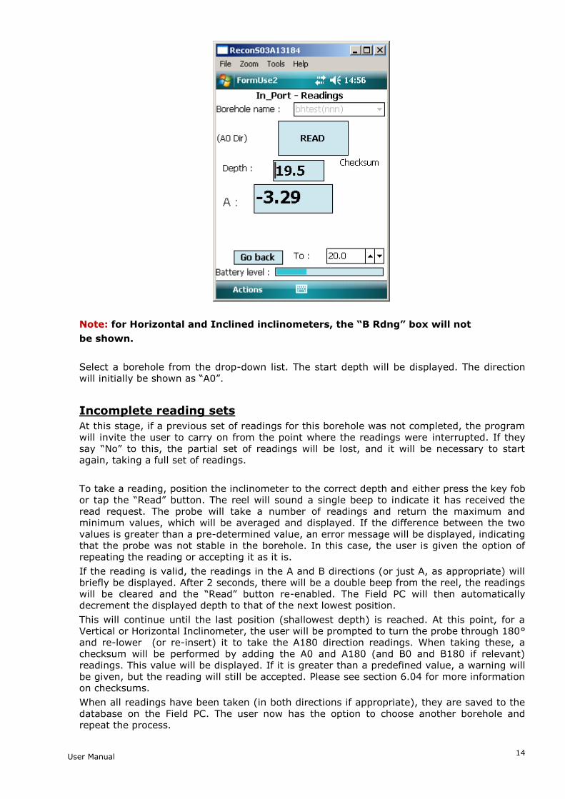
4.13 Comparison of Last Two Reading Sets
In-Port version 2.7 onwards has the facility to graph the difference between the last two reading sets (surveys) allowing the user to quickly and easily have confidence in the quality of the data just taken, to use this feature, proceed as follows.
At the end of a reading run, the menu option “Actions Compare with last set” will become available. Clicking on this will show the A and B face readings just taken, compared with the previous run. They are shown as variation from that run, so the previous run shows as a straight line at 0, with the new readings shown as difference from the previous reading at the same depth. A screenshot is displayed below. The graph can be expanded to make the differences easier to see. Select ‘Expand’ at the bottom right of the Compare Reading Runs Screen to access this (again, screenshot below).
Above, Compare reading runs screen
User Manual
16
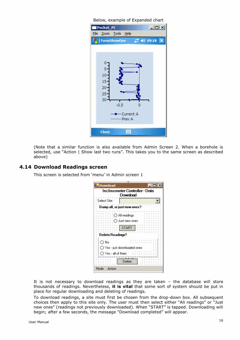
Below, example of Expanded chart
(Note that a similar function is also available from Admin Screen 2. When a borehole is selected, use “Action | Show last two runs”. This takes you to the same screen as described above)
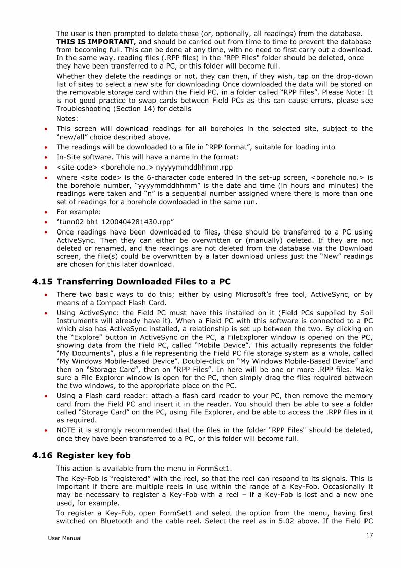
4.14 Download Readings screen
This screen is selected from ‘menu’ in Admin screen 1
It is not necessary to download readings as they are taken – the database will store thousands of readings. Nevertheless, it is vital that some sort of system should be put in place for regular downloading and deleting of readings.
To download readings, a site must first be chosen from the drop-down box. All subsequent choices then apply to this site only. The user must then select either “All readings” or “Just new ones” (readings not previously downloaded). When “START” is tapped. Downloading will begin; after a few seconds, the message “Download completed” will appear.
User Manual
17
The user is then prompted to delete these (or, optionally, all readings) from the database. THIS IS IMPORTANT, and should be carried out from time to time to prevent the database from becoming full. This can be done at any time, with no need to first carry out a download. In the same way, reading files (.RPP files) in the "RPP Files" folder should be deleted, once they have been transferred to a PC, or this folder will become full.
Whether they delete the readings or not, they can then, if they wish, tap on the drop-down list of sites to select a new site for downloading Once downloaded the data will be stored on the removable storage card within the Field PC, in a folder called “RPP Files”. Please Note: It is not good practice to swap cards between Field PCs as this can cause errors, please see Troubleshooting (Section 14) for details
Notes:
This screen will download readings for all boreholes in the selected site, subject to the “new/all” choice described above.
The readings will be downloaded to a file in “RPP format”, suitable for loading into
In-Site software. This will have a name in the format:
<site code> <borehole no.> nyyyymmddhhmm.rpp
where <site code> is the 6-character code entered in the set-up screen, <borehole no.> is the borehole number, “yyyymmddhhmm” is the date and time (in hours and minutes) the readings were taken and “n” is a sequential number assigned where there is more than one set of readings for a borehole downloaded in the same run.
For example:
“tunn02 bh1 1200404281430.rpp”
Once readings have been downloaded to files, these should be transferred to a PC using ActiveSync. Then they can either be overwritten or (manually) deleted. If they are not deleted or renamed, and the readings are not deleted from the database via the Download screen, the file(s) could be overwritten by a later download unless just the “New” readings are chosen for this later download.
4.15 Transferring Downloaded Files to a PC
There two basic ways to do this; either by using Microsoft’s free tool, ActiveSync, or by means of a Compact Flash Card.
Using ActiveSync: the Field PC must have this installed on it (Field PCs supplied by Soil Instruments will already have it). When a Field PC with this software is connected to a PC which also has ActiveSync installed, a relationship is set up between the two. By clicking on the “Explore” button in ActiveSync on the PC, a FileExplorer window is opened on the PC, showing data from the Field PC, called “Mobile Device”. This actually represents the folder “My Documents”, plus a file representing the Field PC file storage system as a whole, called “My Windows Mobile-Based Device”. Double-click on “My Windows Mobile-Based Device” and then on “Storage Card”, then on “RPP Files”. In here will be one or more .RPP files. Make sure a File Explorer window is open for the PC, then simply drag the files required between the two windows, to the appropriate place on the PC.
Using a Flash card reader: attach a flash card reader to your PC, then remove the memory card from the Field PC and insert it in the reader. You should then be able to see a folder called “Storage Card” on the PC, using File Explorer, and be able to access the .RPP files in it as required.
NOTE it is strongly recommended that the files in the folder "RPP Files" should be deleted, once they have been transferred to a PC, or this folder will become full.
4.16 Register key fob
This action is available from the menu in FormSet1.
The Key-Fob is “registered” with the reel, so that the reel can respond to its signals. This is important if there are multiple reels in use within the range of a Key-Fob. Occasionally it may be necessary to register a Key-Fob with a reel – if a Key-Fob is lost and a new one used, for example.
To register a Key-Fob, open FormSet1 and select the option from the menu, having first switched on Bluetooth and the cable reel. Select the reel as in 5.02 above. If the Field PC

User Manual
18
successfully established communication, the screen will now show a large blue message, “PRESS Key-Fob”. Press the Key-Fob briefly until a continuous beep is heard from the cable reel (this will take at least 5 seconds). After a short time, the message “PRESS AGAIN” will appear. Press the Key-Fob once, no sound will be heard. After a short wait, the “OK” message appears, the Key-Fob is now registered with the reel and ready for use.
User Manual
19
Section 5 : Operating Procedure
5.01 Introduction & Reading Overview
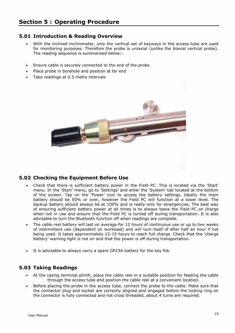
With the inclined inclinometer, only the vertical set of keyways in the access tube are used for monitoring purposes. Therefore the probe is uniaxial (unlike the biaxial vertical probe). The reading sequence is summarised below:-
Ensure cable is securely connected to the end of the probe
Place probe in borehole and position at far end
Take readings at 0.5 metre intervals
5.02 Checking the Equipment Before Use
Check that there is sufficient battery power in the Field PC. This is located via the ‘Start’ menu. In the ‘Start’ menu, go to ‘Settings’ and enter the ‘System’ tab located at the bottom of the screen. Tap on the ‘Power’ icon to access the battery settings. Ideally the main battery should be 50% or over, however the Field PC will function at a lower level. The backup battery should always be at 100% and is really only for emergencies. The best way of ensuring sufficient battery power at all times is to always leave the Field PC on charge when not in use and ensure that the Field PC is turned off during transportation. It is also advisable to turn the Bluetooth function off when readings are complete.
The cable reel battery will last on average for 12 hours of continuous use or up to two weeks of intermittent use (dependent on workload) and will turn itself of after half an hour if not being used. It takes approximately 12-15 hours to reach full charge. Check that the ‘charge battery’ warning light is not on and that the power is off during transportation.
It is advisable to always carry a spare GP23A battery for the key fob.
5.03 Taking Readings
At the casing terminal plinth, place the cable reel in a suitable position for feeding the cable through the access tube and position the cable reel at a convenient location.
Before placing the probe in the access tube, connect the probe to the cable. Make sure that the connector plug and socket are correctly aligned and engaged before the locking ring on the connector is fully connected and not cross threaded, about 4 turns are required.

User Manual
20
Insert the probe into the keyway with the fixed wheels facing downwards and lower to the end of the borehole. Take care to prevent the cable from snagging as it enters the access tube.
From the cable reel location, carefully pull the cable back so that the next 0.5m mark rests on the edge of the access tube. This positions the probe for reading to commence. The distance must be noted for entry into the borehole set-up screen on the Field PC and can be found by examining the cable metre marks.
Turn on the power to the cable reel. Once the power is switched on, a green light will blink intermittently. It is advisable to wait for 5 to 10 minutes for the probe to stabilise (adjust to the temperature in the borehole). Note: Not allowing for temperature stabilisation could result in unstable readings.
Switch on the Field PC and turn the Bluetooth function on by selecting the icon in the bottom right hand corner of the screen and choosing the ‘Turn Bluetooth ON’ option. Once Bluetooth is activated, the icon will turn blue on the Field PC.
Open ‘In-Port’ and Enter User Mode (Take readings). Select the Bluetooth device. Once this is selected, a blue light will be activated on the cable reel informing you that the comms is ready. You can now browse to the pre-defined site required. Once the site is selected, click the Get Readings button. (For more detail, refer to the chapter ‘In-Port’ Software) .
You will now see the depth of the installation displayed and underneath it the reading. Once you are ready, hold the button down on the key fob, (alternatively, the ‘Read’ button can be used and if preferred this can be pressed using your finger rather than the Stylus.) First, a single beep confirms that the keyfob has been acknowledged, however the reading has not yet been stored, a second double beep confirms the reading has been taken. It is after this second beep that you can continue, pulling up the cable to the next marker. If the reading is not quite stable, a dialogue box will appear informing you that the probe has not yet stabilised. You are given the option of accepting the reading anyway, or cancelling and re-reading the depth.
At every five-metre reading, the background colour of the ‘Depth’ box changes to red, reminding you to check the depth of the cable markers against the depths on the Field PC. This corresponds with the depth markers at these positions on the cable. Using this system means that If a mistake has been made you will only need to go back to the last five meters. To go back, simply press the ‘GO BACK’ button. A dialogue box will ask you to confirm that you want to go back down the borehole, click ‘Yes’. Another box will remind you to lower the probe back to the correct depth. You can now use the up and down arrow keys to scroll to the depth required. When you are ready, simply click the key fob to continue.
Once this process has been completed for the readings a dialogue box will inform you that the borehole readings are completed. Click OK. The reading is now complete. To exit In_Port, go to the Actions tab at the bottom tool bar and choose the exit option.
The readings displayed on the screen whilst taking readings are mm/gauge length or inches/gauge length depending on whether you have a metric or imperial system. I.e. they are reduced incremental data with all calibrations applied.
For downloading the readings, refer to section 5.9 in chapter 5 – ‘In-Port’ Software.

User Manual
21
Section 6 : Maintenance
6.01 Care And Maintenance Of The Inclinometer System
Treat all items with respect and handle with CARE.
Ensure that the Probe Unit and Field PC are protected from shock during transit. Although the system is robust, dropping the probe may cause damage to the sensors, always secure the probe in the probe holder on the cable reel.
Take care not to ‘drop’ the cable markers into the cable gate when changing depth as this will strain the cable and cause accelerated wear to the markers – move the cable from current depth to the next depth carefully.
Ensure that the dust cap is always fitted in the charger socket when the charger is removed.
Always wipe off dirt and moisture from the probe and cable after use.
Do not expose the inclinometer probe to temperatures outside the range of -25 to +75°C.
After use, check that the inclinometer probe it mechanically sound and lubricate the wheels, bracket and spindles with light machine oil. The wheels should be lubricated again directly before the next use.
Keep the cable clean and free from kinks. When lowering the inclinometer probe into the access tube, ensure that the cable is not allowed to chafe against the sharp edge of the casing and that loose cable does not snag against sharp objects.
Check the cable marks periodically against a steel tape laid on a flat surface.
To minimise the risk of the inclinometer probe jamming in the access tube, take the following precautions:
Cap all access tubes which are not being used to prevent foreign matter such as pebbles, pencils etc. falling into the tube.
Where continuous filling is taking place make sure the top of the access tube is at least 1 metre above the surrounding fill material so that it can be seen easily.
Where necessary, use a test probe prior to taking readings.
Place protective barriers around all installations.
If, in spite of these precautions, you experience a jammed probe unit, try to ease it gently past the obstruction. If you have to resort to a sharp tug on the cable limit the operation to the force of one man only - a force in excess of 1500kN may cause failure of the strain cord and thus a lost probe. If the probe appears irretrievably stuck contact Soil Instruments Ltd and seek advice on alternative retrieval methods.
6.02 Charging The System
1. Charging The Field PC
Please refer to the Field PC user manual for guidance.
2. Charging The Inclinometer System
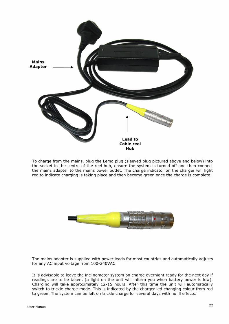
The system is supplied with a mains a charger, which is pictured below
User Manual
22
To charge from the mains, plug the Lemo plug (sleeved plug pictured above and below) into the socket in the centre of the reel hub, ensure the system is turned off and then connect the mains adapter to the mains power outlet. The charge indicator on the charger will light red to indicate charging is taking place and then become green once the charge is complete.
The mains adapter is supplied with power leads for most countries and automatically adjusts for any AC input voltage from 100-240VAC
It is advisable to leave the inclinometer system on charge overnight ready for the next day if readings are to be taken, (a light on the unit will inform you when battery power is low). Charging will take approximately 12-15 hours. After this time the unit will automatically switch to trickle charge mode. This is indicated by the charger led changing colour from red to green. The system can be left on trickle charge for several days with no ill effects.
Mains Adapter
Lead to Cable reel
Hub

User Manual
23
The charger can be used when the cable reel but not the charger, is wet, for example after being used in the rain, but the charging must take place in a dry environment such as in a workshop or office
Always wipe the inclinometer probe unit and cable dry after use, check that the inclinometer probe is mechanically sound and lubricate the wheels etc with light machine oil. The wheels should be lubricated again directly before the next use.
Keep the cable clean and free from kinks. When lowering the inclinometer probe into the access tube ensure that the cable is not allowed to chafe against the sharp edge of the casing and that loose cable does not snag against sharp objects.
Replacing the Battery – Key Fob
It is advisable to always carry a spare GP23A battery for the key fob. To replace the battery, remove the two screws located on the back, (you will need a terminal screwdriver with a Phillips head). Remove old battery and replace with new, ensuring that the battery terminals are in the correct position, (+ and – are marked on the plastic).
6.03 Field PC Battery Life
The Field PC battery life depends on whether the High Capacity battery (standard on systems supplied by Soil Instruments) or the Standard battery is being used, on the backlight settings, the ambient temperature, state of charge and the way in which the system is used. As a guide to battery life a Field PC and Digital Inclinometer were tested in our factory with the inclinometer transmitting readings to the Field PC every 10 seconds (i.e. as fast as the faster operator could use the instrument in the field). This test resulted in the battery life shown in the chart below.
It must be remembered that all batteries decay as the age and therefore it may be necessary to replace the Field PC battery after 12-18 months of use dependant on the site and user requirements. It should also be remembered that the chart on page 23 is a guide, actual performance will vary.
PDA Battery Test With Soil Instruments Digital Inclinometer
0
10
20
30
40
50
60
70
80
90
100
00:0
0
00:3
0
01:0
0
01:3
0
02:0
0
02:3
0
03:0
0
03:3
0
04:0
0
04:3
0
05:0
0
05:3
0
06:0
0
06:3
0
07:0
0
07:3
0
08:0
0
Time in Hours
% C
harg
e R
em
ain
ing
High Capacity Battery,Backlight Set To 100%
High Capacity Battery,Backlight Set To 50%
Field PC battery Test with Digital Inclinometer

User Manual
24
6.04 Calibration
Any inclinometer system should be regularly calibrated to ensure that the readings taken with the system are accurate. Soil Instruments recommends calibration on a yearly basis. To remind the user that the system should be calibrated, after 12 months from the last calibration, when ‘In-Port’ is started on the Field PC a warning message will appear. To keep work interruption to a minimum, this message will appear once every 7 days.
This message can be cleared by tapping the confirmation tab below the message and the system will then respond completely as normal. It is recommended though that the system is returned for calibration as soon as possible.
The User Screen shows a Battery Level bar. Once a reading has been taken (in other words, data have been sent back from the reel), the user screen will show this bar indicating the reel battery level. The bar’s start and end voltages are 13v (right hand end) and 11v (left hand end). It does not change colour at all – the indication of the state of the battery is the position of the bar.
When the reel voltage reaches about 11.8v, a warning is given that the battery is getting low and when it reaches 11.2, a further warning is given that the battery is about to run out.
User Manual
25
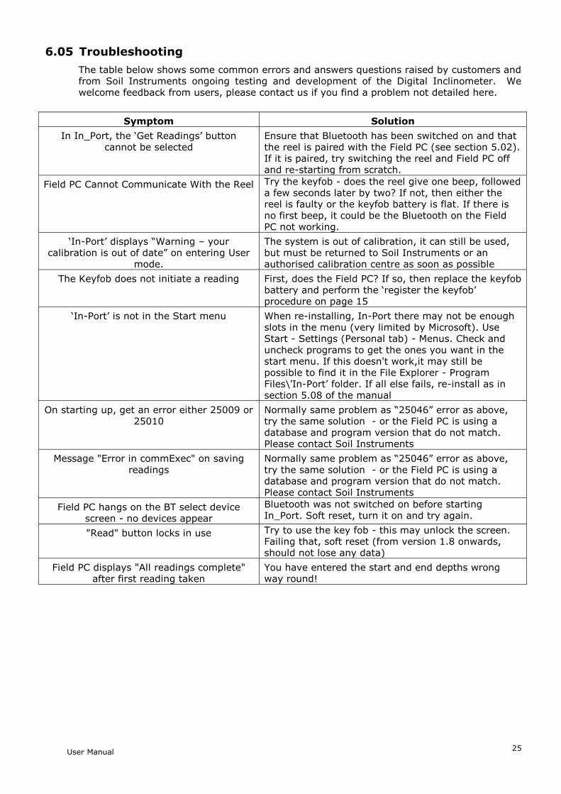
6.05 Troubleshooting
The table below shows some common errors and answers questions raised by customers and from Soil Instruments ongoing testing and development of the Digital Inclinometer. We welcome feedback from users, please contact us if you find a problem not detailed here.
Symptom Solution
In In_Port, the ‘Get Readings’ button cannot be selected
Ensure that Bluetooth has been switched on and that the reel is paired with the Field PC (see section 5.02). If it is paired, try switching the reel and Field PC off and re-starting from scratch.
Field PC Cannot Communicate With the Reel Try the keyfob - does the reel give one beep, followed a few seconds later by two? If not, then either the reel is faulty or the keyfob battery is flat. If there is no first beep, it could be the Bluetooth on the Field PC not working.
‘In-Port’ displays “Warning – your calibration is out of date” on entering User
mode.
The system is out of calibration, it can still be used, but must be returned to Soil Instruments or an authorised calibration centre as soon as possible
The Keyfob does not initiate a reading First, does the Field PC? If so, then replace the keyfob battery and perform the ‘register the keyfob’ procedure on page 15
‘In-Port’ is not in the Start menu When re-installing, In-Port there may not be enough slots in the menu (very limited by Microsoft). Use Start - Settings (Personal tab) - Menus. Check and uncheck programs to get the ones you want in the start menu. If this doesn't work,it may still be possible to find it in the File Explorer - Program Files\’In-Port’ folder. If all else fails, re-install as in section 5.08 of the manual
On starting up, get an error either 25009 or 25010
Normally same problem as “25046” error as above, try the same solution - or the Field PC is using a database and program version that do not match. Please contact Soil Instruments
Message "Error in commExec" on saving readings
Normally same problem as “25046” error as above, try the same solution - or the Field PC is using a database and program version that do not match. Please contact Soil Instruments
Field PC hangs on the BT select device screen - no devices appear
Bluetooth was not switched on before starting In_Port. Soft reset, turn it on and try again.
"Read" button locks in use Try to use the key fob - this may unlock the screen. Failing that, soft reset (from version 1.8 onwards, should not lose any data)
Field PC displays "All readings complete" after first reading taken
You have entered the start and end depths wrong way round!
User Manual
26
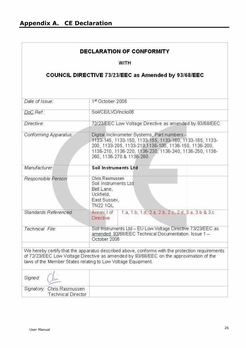
Appendix A. CE Declaration

User Manual
27

User Manual
28
Bell Lane, Uckfield, East Sussex
TN22 1QL, United Kingdom t: +44 (0) 1825 765044 e: [email protected] w: www.soilinstruments.com
Soil Instruments Ltd. Registered in England. Number: 07960087. Registered Office: 3rd Floor, Ashley Road, Altrincham, Cheshire, WA14 2DT
Top Related