


Languages
Pages
Legal


MACHINE VISION GROUP
GPGPU-based surface inspection from structured
white lightMiguel Bordallo1, Karri Niemelä 2, Olli Silvén1
1 Center for Machine Vision Research - University of Oulu, Finland2 VTT - Technical Research Center of Finland, Oulu, Finland
Jari Hannuksela, Olli SilvénMachine Vision Group, Infotech Oulu
Department of Electrical and Information EngineeeringUniversity of Oulu, Finland

MACHINE VISION GROUP
Contents
IntroductionAutomatic Surface Inspection
• Phase extraction from white structured light• Practical problems
Measuring Prototype• Design and construction• GPU as a computing engine• Experimental setup
Description of the system • Algorithms and Implementation
Experiments• Qualitative results• Speed and scalability
Summary

MACHINE VISION GROUP
Motivation
• Automatic surface inspection used in the industry:– To detect all kinds of surface defects – To measure the overall quality of a produced
piece
• Most convenient inspection method should provide exact 3D information
• High speed of production lines need:– Fast imaging methods – Lots of computational power
• Systems must be cost effective:– Standard PCs – Graphics Processing Units (GPUs)

MACHINE VISION GROUP
GPU as a computing engine
• All computers and many embedded systems include a GPU• Standard PCs and components• Cost-effective systems• Highly scalable• GPU can be treated as an independent entity
• Graphics Processing Units offer important parallelization capabilities• GPUs offer ”many-core” computation• Thousands of threads can be executed concurrently.• GPU and CPU can be used concurrently• If data transfer is small, CPU load remains low (CPU can be used for other tasks)
• CUDA is a highly optimized and attractive accelerator interface

MACHINE VISION GROUP
Surface topography from white structured light (SLS)
• Phase-shifting methods:– Based on fringe pattern projections or structured light – Extensively utilized in topography measurement– Provide for high resolution height measurements on each
pixel.
• The illuminator projects a sine pattern:– On a moving target – In a synchronized manner
• The camera system obtains suitable input pictures using:– Pulse-like illumination – Synchronized camera subsystem – Certain known rate

MACHINE VISION GROUP
Phase measurement
In practice δ1, δ2, δ3 are not known in beforehand
If δ1, δ2, δ3 are known:
And the height:
The input images are defined by the following:
MACHINE VISION GROUP
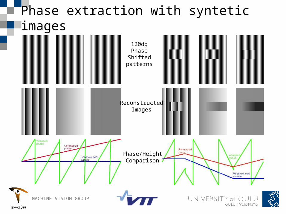
Phase extraction with syntetic images
120dgPhaseShifted
patterns
ReconstructedImages
Phase/HeightComparison

MACHINE VISION GROUP
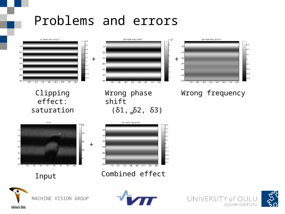
Problems and errors
Clipping effect: saturation
Wrong phase shift
(δ1, δ2, δ3)
Wrong frequency
Combined effect
+ +
=
MACHINE VISION GROUP
Problems and errors
Clipping effect: saturation
Wrong frequency
Combined effectInput
+ +
=
+
Wrong phase shift
(δ1, δ2, δ3)

MACHINE VISION GROUP
Problems and errors
Clipping effect: saturation
Wrong frequency
Combined effectInput Result
+ +
=
+ =
Wrong phase shift
(δ1, δ2, δ3)

MACHINE VISION GROUP
Prototype design

MACHINE VISION GROUP
Prototype design
• VTT prototype: Sine period of 250um– Camera: Basler Scout scA 1600-14gm. 1628x1236 pixels, Area
4.4*4.4um2– Interface: GiGE, 17 frames per second– Optics: Optosigma Telecentric (TC1236). Pixel size 30 µm – Illuminator: 9 Luxeon K2 Red LEDS + collimating lens. 3 channels
• Laptop: Lenovo W700– CPU: Intel Core 2 Extreme QX9300 2.53 GHz – GPU: Nvidia Quadro FX3700 (128 cores)– IDE: Visual Studio. CUDA & C code environments
• Motor Line Controller: ATMEL microcontroler and PC– Line speed: 0,3 m/s
• Samples used: – Offline: 10 cents coin, printed electronics (10 µm thick)– Online: MDF-fiberboard

MACHINE VISION GROUP
Prototype construction

MACHINE VISION GROUP
Application flow

MACHINE VISION GROUP
Application flow

MACHINE VISION GROUP
Application flow

MACHINE VISION GROUP
Application flow

MACHINE VISION GROUP
Application flow

MACHINE VISION GROUP
Application flow

MACHINE VISION GROUP
Application flow

MACHINE VISION GROUP
Application flow

MACHINE VISION GROUP
Input images
Full frame size: 1628x1236 pixels, 8 or 10 bpp, grayscale, 17 fps

MACHINE VISION GROUP
Input images
64x256 correlation area
Full frame size: 1628x1236 pixels, 8 or 10 bpp, grayscale, 17 fps

MACHINE VISION GROUP
Image registration
• Based on modified phase correlation– Tukey window + FFT-based (+ Gaussian filtering)– Robust to blur (even motion blur)– Robust to image intensity changes– Fast to compute
• Easy to parallelize– CUDA FFT routines already optimized– Per-pixel operations
• Identifies corresponding pixels– Subpixel level access as a CUDA texture object
• Predict initial phase shift for phase computation• Fine tune the motor displacements & camera
rate
600x300ROIs
MACHINE VISION GROUP
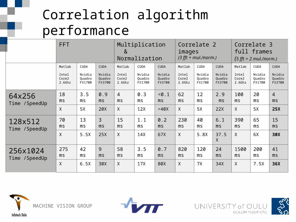
Correlation algorithm performance
FFT Multiplication & Normalization
Correlate 2 images (3 fft + mul./norm.)
Correlate 3 full frames(5 fft + 2 mul./norm.)
Matlab
Intel Core22.6Ghz
CUDA
NvidiaQuadroFX1700
CUDA
NvidiaQuadroFX3700
Matlab
Intel Core22.6Ghz
CUDA
NvidiaQuadroFX1700
CUDA
NvidiaQuadroFX3700
Matlab
Intel Core22.6Ghz
CUDA
NvidiaQuadroFX1700
CUDA
NvidiaQuadroFX3700
Matlab
Intel Core22.6Ghz
CUDA
NvidiaQuadroFX1700
CUDA
NvidiaQuadroFX3700
64x256Time /SpeedUp
18 ms
3.5 ms
0.9 ms
4 ms
0.3 ms
<0.1 ms
62 ms
12 ms
2.9 ms
100 ms
20 ms
4 ms
X 5X 20X X 12X >40X X 5X 22X X 5X 25X
128x512Time /SpeedUp
70 ms
13 ms
3 ms
15 ms
1.1 ms
0.2 ms
230 ms
40 ms
6.1 ms
390 ms
65 ms
15 ms
X 5.5X 25X X 14X 67X X 5.8X 37.5X
X 6X 30X
256x1024Time /SpeedUp
275 ms
42 ms
9 ms
58 ms
3.5 ms
0.7 ms
820 ms
120 ms
24 ms
1500 ms
200 ms
41 ms
X 6.5X 30X X 17X 80X X 7X 34X X 7.5X 36X

MACHINE VISION GROUP
Advanced Phase Shifting Algorithm (APSA)
• First introduced by Z. Wang in 2004 • Iterative algorithm
– Initial estimation of phase difference (δ1, δ2, δ3)• from correlation and previous frames
– Phase of each pixel is computed• Using a CUDA 2-dimensional kernel
– Average phase of the image is computed• By adding together the values of all the pixels• Using CUDPP parallel reductions
– Average phase is the new phase difference– Iterate until convergent and error < threshold
• Result is a phase wrapped image– Range between -π and π
Wrapped image

MACHINE VISION GROUP
APSA times
Algorithm MATLAB time C/CUDA time Size Mpix/s
SpeedUp
APSA1: Phase extraction (CUDA)
130,0 ms/iteration 10,9 ms/iteration
350x826
26,52 11x
APSA2: Average phase (CUDA)
470,0 ms/iteration 18,8 ms/iteration
350x826
15,11 24x
APSA 10 iterations 6200 ms 300 ms 350x826
0,95 20x
MACHINE VISION GROUP
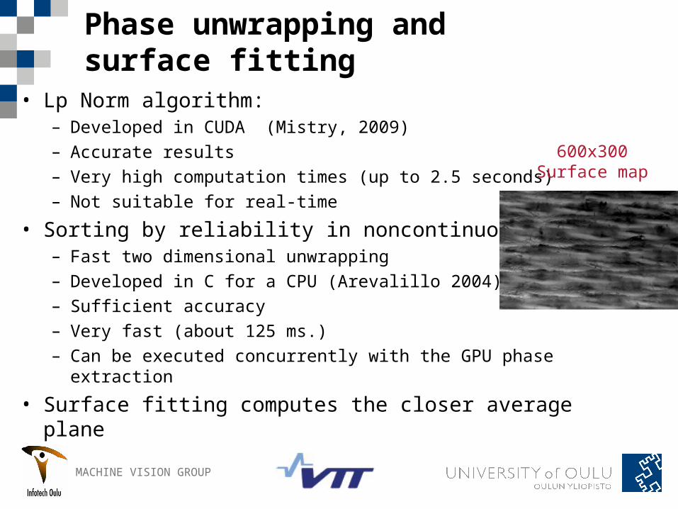
Phase unwrapping and surface fitting
• Lp Norm algorithm:– Developed in CUDA (Mistry, 2009)– Accurate results– Very high computation times (up to 2.5 seconds)– Not suitable for real-time
• Sorting by reliability in noncontinuous path:– Fast two dimensional unwrapping– Developed in C for a CPU (Arevalillo 2004)– Sufficient accuracy– Very fast (about 125 ms.)– Can be executed concurrently with the GPU phase
extraction
• Surface fitting computes the closer average plane
600x300Surface map

MACHINE VISION GROUP
Display system

MACHINE VISION GROUP
Automatic calibration system
• Phase maps measured continuously in real time– The information of the phase extraction process can be
used to improve further results and conditions.
• Synchronizes – Illumination, – Camera capture– Motor speed
• Input parameters:– Correlation results (adjust motor speed)– Phase average (adjust illumination and camera capture
Phase tuning and system calibration improve the results gradually

MACHINE VISION GROUP
Real-time tests: MDF fibreboard sample

MACHINE VISION GROUP
Real time tests: 3D representation

MACHINE VISION GROUP
Printed electronics sample

MACHINE VISION GROUP
Complete system
Image size: 3 ROI of 600x300Computation time: < 150 ms.Frame rate: > 5 fps.Resolution: 30µm per pixel. Phase
unwrapping
Copy Images as texture
Get input framesN = 1
CPU GPU
Get Correlation ROI
Get SurfaceROI
Get pixel phase
Get average phaseAPSA1
Get average phaseAPSA2
Get phase map
Surface fitting
Forward correlation
values
Forward phase average values
Perform correlation

MACHINE VISION GROUP
Complete system
Image size: 3 ROI of 600x300Computation time: < 150 ms.Frame rate: > 5 fps.Resolution: 30µm per pixel. Phase
unwrapping
Get input framesN = 1
CPU GPU
Surface fitting
Forward correlation
values
Forward phase average values
Copy Images as texture
Get Correlation ROI
Get SurfaceROI
Get pixel phase
Get average phaseAPSA1
Get average phaseAPSA2
Get phase map
Perform correlation

MACHINE VISION GROUP
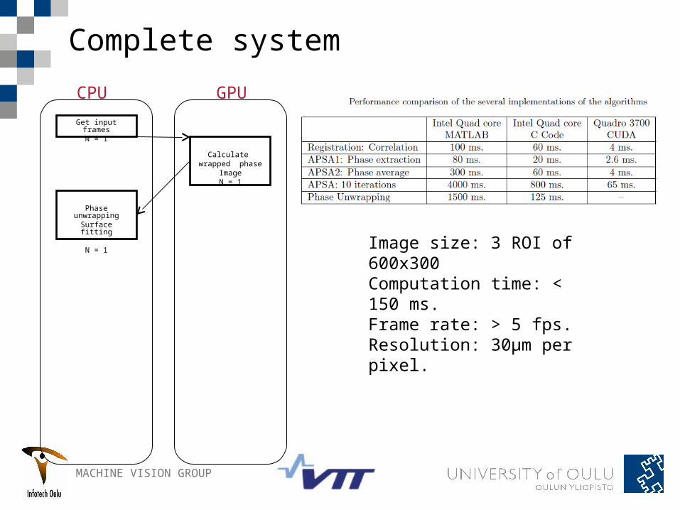
Complete system
Image size: 3 ROI of 600x300Computation time: < 150 ms.Frame rate: > 5 fps.Resolution: 30µm per pixel. Phase
unwrapping
Surface ftting
Get input framesN = 1
CPU GPU
Calculate wrapped phase
ImageN = 1
MACHINE VISION GROUP
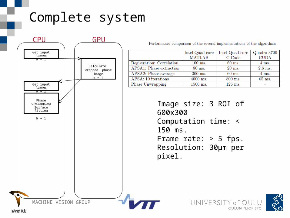
Complete system
Image size: 3 ROI of 600x300Computation time: < 150 ms.Frame rate: > 5 fps.Resolution: 30µm per pixel.
Phase unwrapping
Surface fitting
N = 1
Calculate wrapped phase
ImageN = 1
Get input framesN = 1
CPU GPU
MACHINE VISION GROUP
Complete system
Image size: 3 ROI of 600x300Computation time: < 150 ms.Frame rate: > 5 fps.Resolution: 30µm per pixel.
Phase unwrapping
Surface fitting
N = 1
Calculate wrapped phase
ImageN = 1
Get input framesN = 1
Get input framesN = 2
CPU GPU

MACHINE VISION GROUP
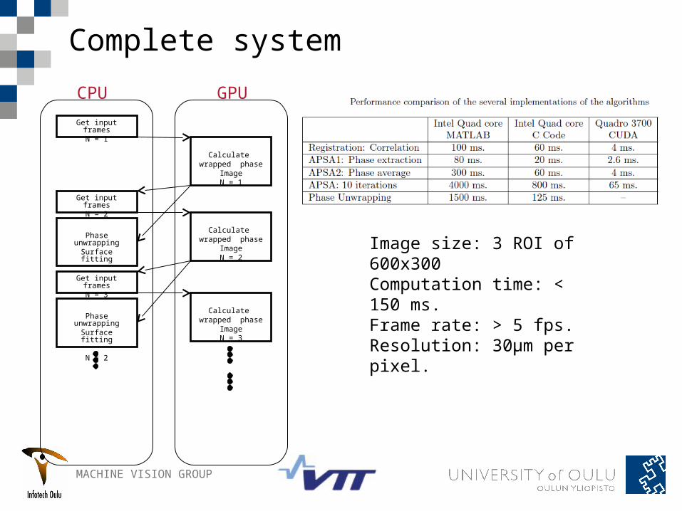
Complete system
Image size: 3 ROI of 600x300Computation time: < 150 ms.Frame rate: > 5 fps.Resolution: 30µm per pixel.
Phase unwrapping
Surface fitting
N = 1
Calculate wrapped phase
ImageN = 1
Calculate wrapped phase
ImageN = 2
Get input framesN = 1
Get input framesN = 2
CPU GPU

MACHINE VISION GROUP
Complete system
Image size: 3 ROI of 600x300Computation time: < 150 ms.Frame rate: > 5 fps.Resolution: 30µm per pixel.
Phase unwrapping
Surface fitting
N = 1
Calculate wrapped phase
ImageN = 1
Calculate wrapped phase
ImageN = 2
Phase unwrapping
Surface fitting
N = 2
Calculate wrapped phase
ImageN = 3
Get input framesN = 1
Get input framesN = 2
Get input framesN = 3
CPU GPU

MACHINE VISION GROUP
Complete system
Image size: 3 ROI of 600x300Computation time: < 150 ms.Frame rate: > 5 fps.Resolution: 30µm per pixel.
Phase unwrapping
Surface fitting
N = 1
Calculate wrapped phase
ImageN = 1
Calculate wrapped phase
ImageN = 2
Phase unwrapping
Surface fitting
N = 2
Calculate wrapped phase
ImageN = 3
Get input framesN = 1
Get input framesN = 2
Get input framesN = 3
Get input framesN = n
Phase unwrapping
Surface fitting
N = n-1
Calculate wrapped phase
ImageN = n
CPU GPU

MACHINE VISION GROUP
Summary• A sine projection technique is a suitable method to optically measure a layer-like surface topography
• The system could be used in rapid motor lines with proper synchronization
• An integrated automatic calibration system helps synchronization and increases quality and robustness
•High accuracy can be achieved with fast imaging methods and intensive computation
• Time critical algorithms can be executed with GPU-based parallel computing

MACHINE VISION GROUP
Thank you!
• Any questions ???
Top Related