


Languages
Pages
Legal


101
44–6 mm 99 0429 82 046–8 mm 99 0429 282 04
54–6 mm 99 0437 82 056–8 mm 99 0437 282 05
8 6–8 mm 99 0487 282 08
44–6 mm 99 0429 43 046–8 mm 99 0429 57 04
54–6 mm 99 0437 43 056–8 mm 99 0437 57 05
4 4–6 mm 99 0529 14 04
~60
Ø 20
M12 x
1
SW 18mm
Ø 20
,2M1
2 x 1
SW 18mm SW 14mm SW 13mm
~60
Ø 20
,2M1
2 x 1
SW 18mm SW 14mm SW 13mm
~60
~60
Ø 20
M12 x
1
Automation Technology 713 series
Contacts 3 4 5 8 12
Wire gauge max. 0,75 mm2 (max. AWG 20), Power max. 1,5 mm2 (max. AWG 16), screw clamp 0,14–0,75 mm2 (AWG 26–18) max. 0,5 mm2 (max. AWG 20) max. 0,25 mm2 (max. AWG 24)
Mechanical operation Optalloy > 50 Mating cycles, Gold > 100 Mating cycles Gold > 100 Mating cycles
Temperature range – 40 °C /+ 85 °C, Outdoor – 40 °C /+ 100 °C, screw clamp – 25 °C /+ 80 °C
Rated voltage 250 V 60 V 30 V
Pollution degree 3
Rated current (40°C) 4 A 4 A, Power 8 A 4 A, Power cont. 1-4 8 A, cont. 5 2 A 2 A 1,5 A
Contact plating screw clamp termination: CuSnZn (Optalloy), others Au (Gold) Au (Gold)
Material of housing PA
Specifications Cable connector plastic version
Description Drawing
Male cable connector, screw clamp, solder termination on contact 12/wire clamp
Male cable connector, stainless steel locking ring, screw clamp
Male cable connector, plastic locking system, screw clamp
Male cable connector, crimp
• Screw locking acc. to DIN EN 61076-2-101• Degree of protection IP67• Moulded versions• Easy assembly• Excellent EMC shielding • Versions with shielding rings/iris type spring• Angled connectors adjustable in 4 positions• Outdoor versions
Degree of protection IP68/IP69
M12 A-Coding
Contacts Cable outlet Screw clamp 1) Wire clamp
34–6 mm 99 0429 07 04 –6–8 mm 99 0429 158 04 –
4
2,5–3,5 mm 99 0429 314 04 –4–6 mm 99 0429 14 04 99 0525 14 046–8 mm 99 0429 12 04 99 0525 12 04
54–6 mm 99 0437 14 05 99 0537 14 056–8 mm 99 0437 12 05 99 0537 12 05
8 6–8 mm 99 0487 12 08 –
12 1) 6–8 mm 99 0491 12 12 –
More versions and information on www.binder-connector.com 1) Version with solder contacts.
Crimp contacts see page 103/129
NEW
102
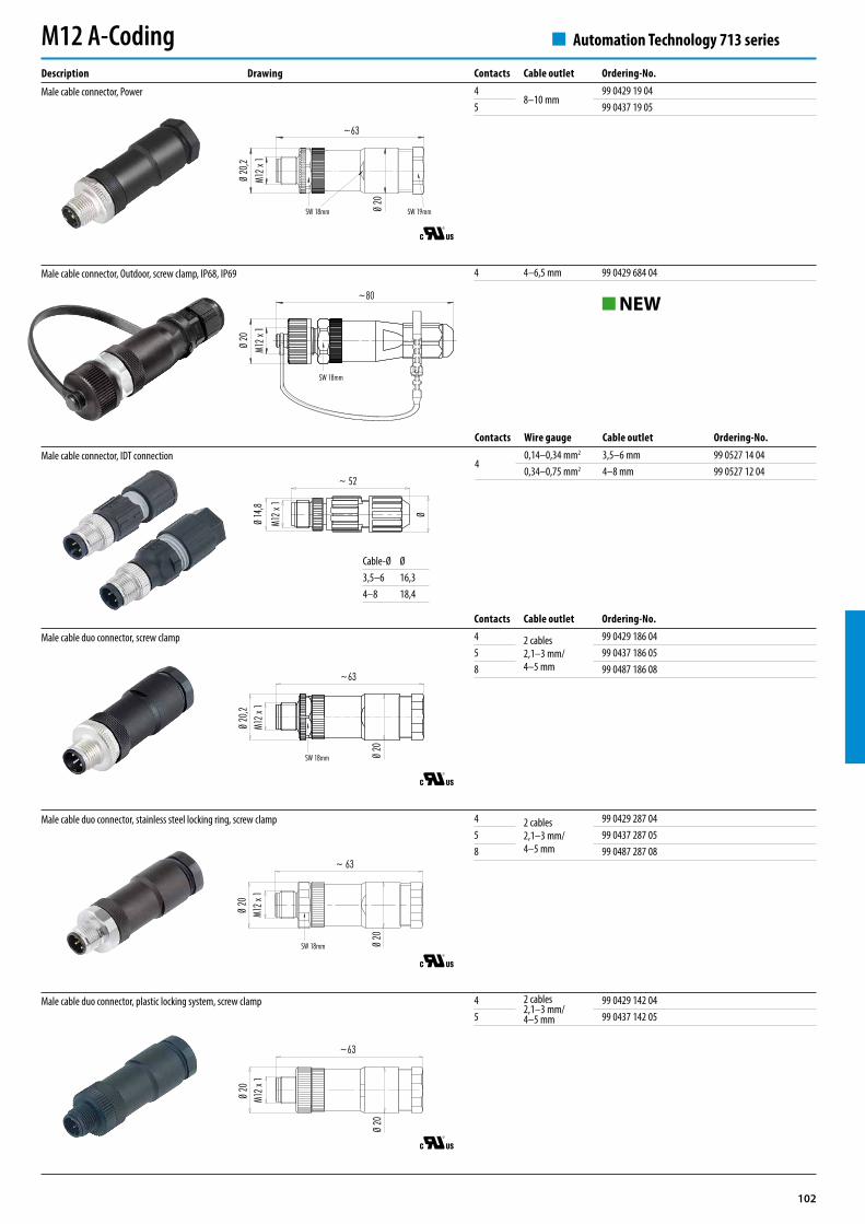
4 4–6,5 mm 99 0429 684 04M1
2 x 1
Ø 20
,2
~63
SW 18mm Ø 20
SW 19mm
M12 x
1Ø
20
~80
SW 18mm
Ø
~ 52
Ø 14
,8
M12 x
1
~63
Ø 20
,2M1
2 x 1
Ø 20
SW 18mm
M12 x
1
Ø 20
~ 63
Ø 20
SW 18mm
~63
Ø 20
M12 x
1
Ø 20
Contacts Cable outlet Ordering-No.4
8–10 mm99 0429 19 04
5 99 0437 19 05
Contacts Cable outlet Ordering-No.4 2 cables
2,1–3 mm/4–5 mm
99 0429 186 045 99 0437 186 058 99 0487 186 08
Automation Technology 713 series
Description Drawing
Male cable connector, Power
Male cable connector, Outdoor, screw clamp, IP68, IP69
Male cable connector, IDT connection
Male cable duo connector, screw clamp
Male cable duo connector, stainless steel locking ring, screw clamp
Male cable duo connector, plastic locking system, screw clamp
M12 A-Coding
Cable-Ø Ø3,5–6 16,34–8 18,4
Contacts Wire gauge Cable outlet Ordering-No.
40,14–0,34 mm2 3,5–6 mm 99 0527 14 040,34–0,75 mm2 4–8 mm 99 0527 12 04
4 2 cables2,1–3 mm/4–5 mm
99 0429 287 045 99 0437 287 058 99 0487 287 08
4 2 cables2,1–3 mm/4–5 mm
99 0429 142 045 99 0437 142 05
NEW
103
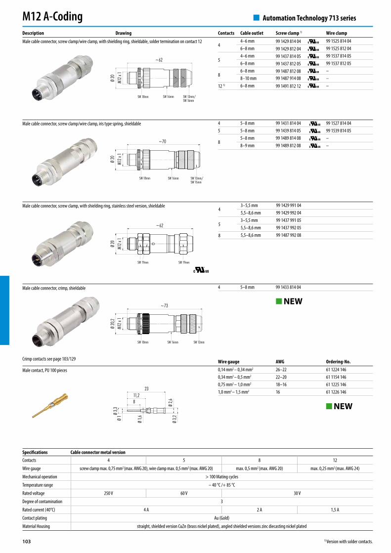
4 5–8 mm 99 1431 814 04 99 1527 814 045 5–8 mm 99 1439 814 05 99 1539 814 05
85–8 mm 99 1489 814 08 –8–9 mm 99 1489 812 08 –
~62
Ø 20
M12 x
1
SW 18mm SW 16mm SW 13mm/SW 16mm
M12 x
1
~70
Ø 20
SW 18mm SW 16mm SW 13mm/SW 15mm
43–5,5 mm 99 1429 991 045,5–8,6 mm 99 1429 992 04
53–5,5 mm 99 1437 991 055,5–8,6 mm 99 1437 992 05
8 5,5–8,6 mm 99 1487 992 08
M12 x
1Ø 2
0
~62
SW 19mm SW 19mm
M12 x
1
~73
Ø 20
,2
SW 18mm SW 16mm SW 13mm
4 5–8 mm 99 1433 814 04
11,28
Ø 1,6
23
Ø 1Ø
3,3
Ø 2,6
Ø 3,2
Automation Technology 713 series
Contacts 4 5 8 12
Wire gauge screw clamp max. 0,75 mm2 (max. AWG 20), wire clamp max. 0,5 mm2 (max. AWG 20) max. 0,5 mm2 (max. AWG 20) max. 0,25 mm2 (max. AWG 24)
Mechanical operation > 100 Mating cycles
Temperature range – 40 °C /+ 85 °C
Rated voltage 250 V 60 V 30 V
Degree of contamination 3
Rated current (40°C) 4 A 2 A 1,5 A
Contact plating Au (Gold)
Material Housing straight, shielded version CuZn (brass nickel plated), angled shielded versions zinc diecasting nickel plated
Specifications Cable connector metal version
Description Drawing
Male cable connector, screw clamp/wire clamp, with shielding ring, shieldable, solder termination on contact 12
Male cable connector, screw clamp/wire clamp, iris type spring, shieldable
Male cable connector, crimp, shieldable
Male cable connector, screw clamp, with shielding ring, stainless steel version, shieldable
M12 A-CodingContacts Cable outlet Screw clamp 1) Wire clamp
44–6 mm 99 1429 814 04 99 1525 814 046–8 mm 99 1429 812 04 99 1525 812 04
54–6 mm 99 1437 814 05 99 1537 814 056–8 mm 99 1437 812 05 99 1537 812 05
86–8 mm 99 1487 812 08 –8–10 mm 99 1487 914 08 –
12 1) 6–8 mm 99 1491 812 12 –
Crimp contacts see page 103/129
NEW
Male contact, PU 100 pieces
Wire gauge AWG Ordering-No.0,14 mm2 – 0,34 mm2 26–22 61 1224 1460,34 mm2 – 0,5 mm2 22–20 61 1154 1460,75 mm2 – 1,0 mm2 18–16 61 1225 1461,0 mm2 – 1,5 mm2 16 61 1226 146
NEW
1) Version with solder contacts.
104
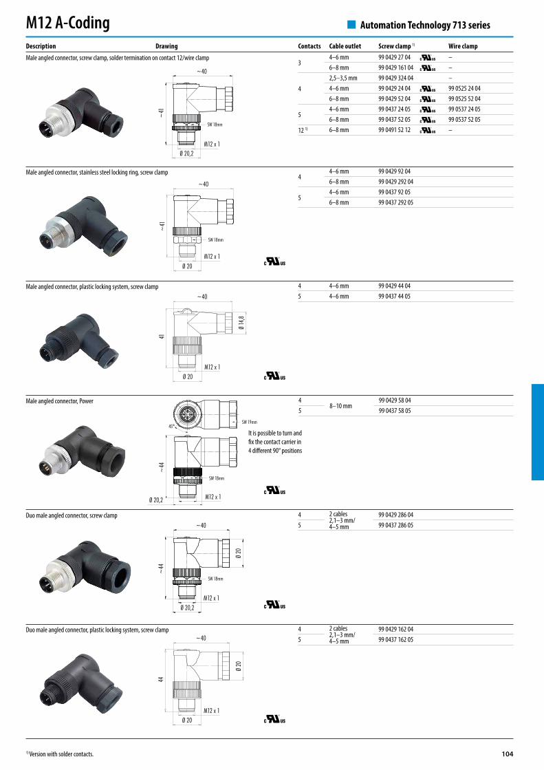
44–6 mm 99 0429 92 046–8 mm 99 0429 292 04
54–6 mm 99 0437 92 056–8 mm 99 0437 292 05
4 4–6 mm 99 0429 44 045 4–6 mm 99 0437 44 05
44
Ø 20M12 x 1
~40
Ø 20
~44
Ø 20,2M12 x 1
~40
Ø 20
SW 18mm
~44
M12 x 1
45°
Ø 20,2
SW 18mm
SW 19mm
M12 x 1Ø 20
41
Ø 14
,8
~40
~41
Ø 20,2M12 x 1
~40
SW 18mm
~40
M12 x 1Ø 20
~41
SW 18mm
48–10 mm
99 0429 58 045 99 0437 58 05
Automation Technology 713 series
Description Drawing
M12 A-Coding
Male angled connector, screw clamp, solder termination on contact 12/wire clamp
Male angled connector, stainless steel locking ring, screw clamp
Male angled connector, plastic locking system, screw clamp
Male angled connector, Power
Duo male angled connector, screw clamp
Duo male angled connector, plastic locking system, screw clamp
Contacts Cable outlet Screw clamp 1) Wire clamp
34–6 mm 99 0429 27 04 –6–8 mm 99 0429 161 04 –
4
2,5–3,5 mm 99 0429 324 04 –4–6 mm 99 0429 24 04 99 0525 24 046–8 mm 99 0429 52 04 99 0525 52 04
54–6 mm 99 0437 24 05 99 0537 24 056–8 mm 99 0437 52 05 99 0537 52 05
12 1) 6–8 mm 99 0491 52 12 –
It is possible to turn and fix the contact carrier in 4 different 90° positions
4 2 cables2,1–3 mm/4–5 mm
99 0429 286 045 99 0437 286 05
4 2 cables2,1–3 mm/4–5 mm
99 0429 162 045 99 0437 162 05
1) Version with solder contacts.
105
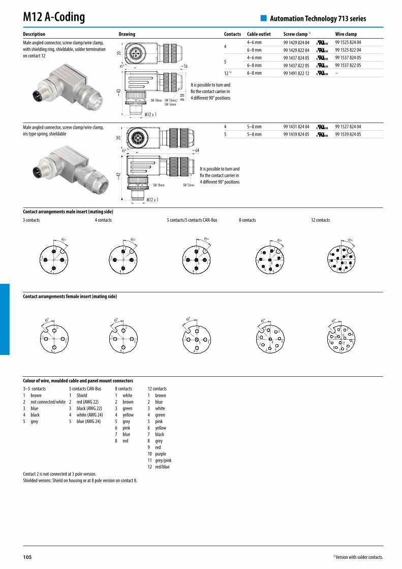
4 5–8 mm 99 1431 824 04 99 1527 824 045 5–8 mm 99 1439 824 05 99 1539 824 05
20
~56
~43
M12 x 1
Ø 18
SW 18mm
45°
SW 13mm/SW 16mm
~42
~64
20
M12 x 1
SW 18mm
45°
SW 13mm
1
23
4
56
7 8
45°
9
10
11 121
2
3
4
45°
1
2
3
4
5
45°
1
23
4
5 67
8
45°
1
2
3
4
45°
1
2 34
5
678
910 11
12
45°
1
2
3
4
45°
1
2
3
4
45°
1
2
3
4
5
45°
1
23
4
56
7 8
45°
Automation Technology 713 seriesM12 A-Coding
Contact arrangements male insert (mating side)
Contact arrangements female insert (mating side)
4 contacts 5 contacts/5 contacts CAN-Bus 12 contacts8 contacts3 contacts
Colour of wire, moulded cable and panel mount connectors3–5 contacts 5 contacts CAN-Bus 8 contacts 12 contacts12345
brownnot connected/whiteblueblackgrey
12345
Shieldred (AWG 22)black (AWG 22)white (AWG 24)blue (AWG 24)
12345678
whitebrowngreenyellowgreypinkbluered
123456789101112
brownbluewhitegreenpinkyellowblackgreyredpurplegrey/pinkred/blue
Contact 2 is not connected at 3 pole version.Shielded verions: Shield on housing or at 8 pole version on contact 8.
Description Drawing
Male angled connector, screw clamp/wire clamp, iris type spring, shieldable
Contacts Cable outlet Screw clamp 1) Wire clamp
44–6 mm 99 1429 824 04 99 1525 824 046–8 mm 99 1429 822 04 99 1525 822 04
54–6 mm 99 1437 824 05 99 1537 824 056–8 mm 99 1437 822 05 99 1537 822 05
12 1) 6–8 mm 99 1491 822 12 –
Male angled connector, screw clamp/wire clamp, with shielding ring, shieldable, solder termination on contact 12
It is possible to turn and fix the contact carrier in 4 different 90° positions
It is possible to turn and fix the contact carrier in 4 different 90° positions
1) Version with solder contacts.
106
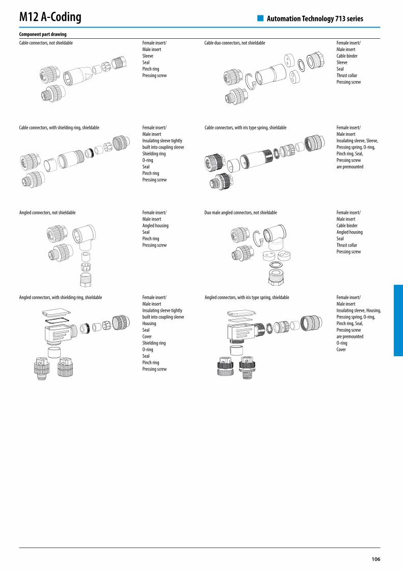
Automation Technology 713 seriesM12 A-CodingComponent part drawing
Cable connectors, not shieldable
Angled connectors, not shieldable
Cable duo connectors, not shieldable
Duo male angled connectors, not shieldable
Female insert/Male insertSleeveSealPinch ringPressing screw
Female insert/Male insertAngled housing SealPinch ringPressing screw
Female insert/Male insertCable binderSleeveSealThrust collarPressing screw
Female insert/Male insertCable binderAngled housing SealThrust collarPressing screw
Cable connectors, with shielding ring, shieldable
Angled connectors, with shielding ring, shieldable
Cable connectors, with iris type spring, shieldable
Angled connectors, with iris type spring, shieldable
Female insert/Male insertInsulating sleeve tightly built into coupling sleeveShielding ringO-ringSealPinch ringPressing screw
Female insert/Male insertInsulating sleeve tightly built into coupling sleeveHousingSealCoverShielding ringO-ringSealPinch ringPressing screw
Female insert/Male insertInsulating sleeve, Sleeve, Pressing spring, O-ring,Pinch ring, Seal,Pressing screware premounted
Female insert/Male insertInsulating sleeve, Housing, Pressing spring, O-ring,Pinch ring, Seal,Pressing screw are premountedO-ringCover
107
Ø 14
,5
48,431
L
Ø 14
,5M1
2 x 1
Kabel-Ø ≤ 5,5 mm Kabel-Ø > 5,5 mm
Ø 9
Ø 12
,6
SW 13mm
Ø 14
,5
48,431
L
Ø 14
,5M1
2 x 1
SW 13mm
Ø 14
,5M1
2 x 1 48,5 L
Ø 14
,5
31
Kabel-Ø ≤ 5,5 mm Kabel-Ø > 5,5 mm
Ø 9
Ø 12
,6
EMV
3 x 0,342 m 77 3529 0000 20703–0200 77 3529 0000 50703–02005 m 77 3529 0000 20703–0500 77 3529 0000 50703–0500
4 x 0,342 m 77 3529 0000 20704–0200 77 3529 0000 50704–02005 m 77 3529 0000 20704–0500 77 3529 0000 50704–0500
5 x 0,252 m 77 3529 0000 20705–0200 77 3529 0000 50705–02005 m 77 3529 0000 20705–0500 77 3529 0000 50705–0500
8 x 0,252 m 77 3529 0000 20708–0200 77 3529 0000 50708–02005 m 77 3529 0000 20708–0500 77 3529 0000 50708–0500
Ø 14
,5
48,431
L
Ø 14
,5M1
2 x 1
VASW 13mm
Kabel-Ø ≤ 5,5 mm Kabel-Ø > 5,5 mm
Ø 9
Ø 12
,6
M12 x
1Ø
14,5
Ø 14
,5
48,431
L
SW 13mm
M12 x
1Ø
14,5
Ø 14
,5
48,431
SW 13mm
5 – 77 9839 0000 00005
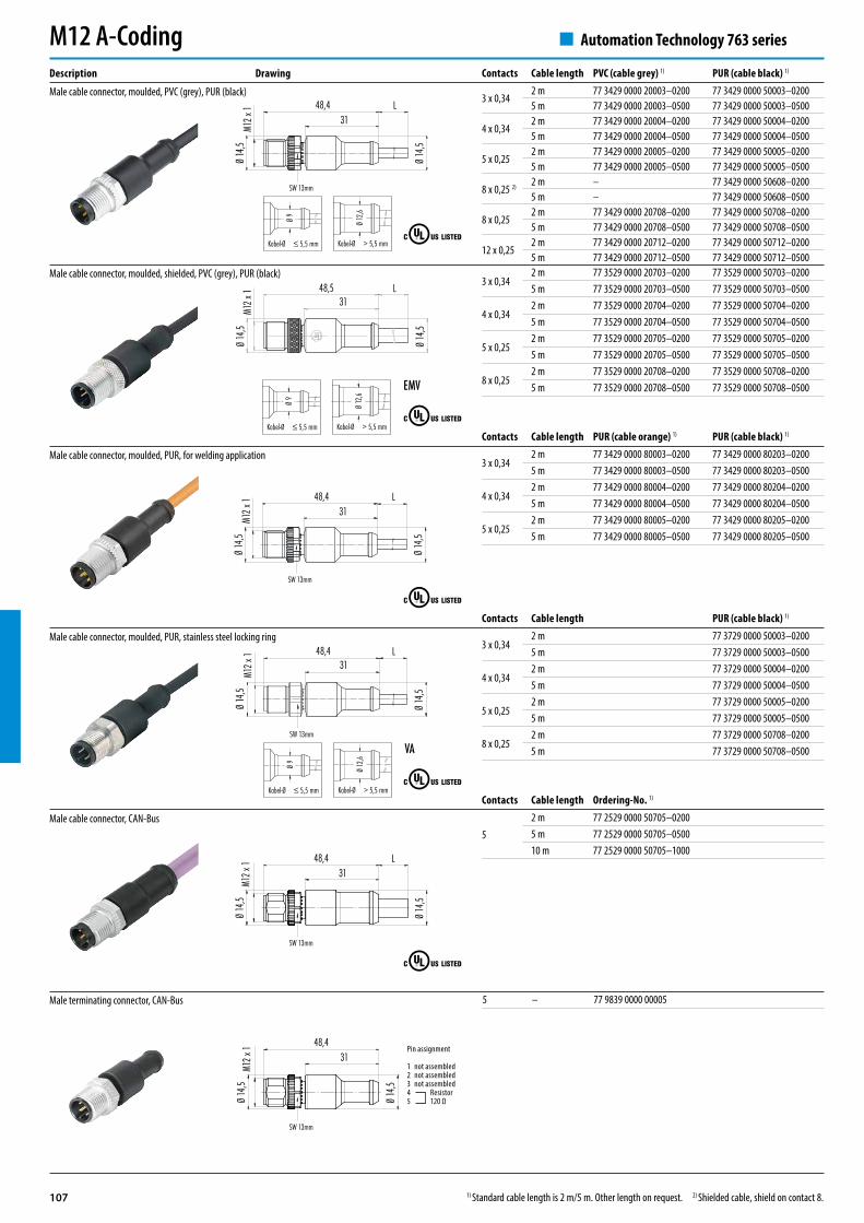
Automation Technology 763 series
Description Drawing
Male cable connector, moulded, PVC (grey), PUR (black)
Male cable connector, moulded, PUR, for welding application
Male cable connector, moulded, PUR, stainless steel locking ring
Male cable connector, CAN-Bus
Male terminating connector, CAN-Bus
Male cable connector, moulded, shielded, PVC (grey), PUR (black)
M12 A-Coding
1) Standard cable length is 2 m/5 m. Other length on request. 2) Shielded cable, shield on contact 8.
Contacts Cable length PVC (cable grey) 1) PUR (cable black) 1)
3 x 0,342 m 77 3429 0000 20003–0200 77 3429 0000 50003–02005 m 77 3429 0000 20003–0500 77 3429 0000 50003–0500
4 x 0,342 m 77 3429 0000 20004–0200 77 3429 0000 50004–02005 m 77 3429 0000 20004–0500 77 3429 0000 50004–0500
5 x 0,252 m 77 3429 0000 20005–0200 77 3429 0000 50005–02005 m 77 3429 0000 20005–0500 77 3429 0000 50005–0500
8 x 0,25 2) 2 m – 77 3429 0000 50608–02005 m – 77 3429 0000 50608–0500
8 x 0,252 m 77 3429 0000 20708–0200 77 3429 0000 50708–02005 m 77 3429 0000 20708–0500 77 3429 0000 50708–0500
12 x 0,252 m 77 3429 0000 20712–0200 77 3429 0000 50712–02005 m 77 3429 0000 20712–0500 77 3429 0000 50712–0500
Contacts Cable length Ordering-No. 1)
52 m 77 2529 0000 50705–02005 m 77 2529 0000 50705–050010 m 77 2529 0000 50705–1000
Contacts Cable length PUR (cable orange) 1) PUR (cable black) 1)
3 x 0,342 m 77 3429 0000 80003–0200 77 3429 0000 80203–02005 m 77 3429 0000 80003–0500 77 3429 0000 80203–0500
4 x 0,342 m 77 3429 0000 80004–0200 77 3429 0000 80204–02005 m 77 3429 0000 80004–0500 77 3429 0000 80204–0500
5 x 0,252 m 77 3429 0000 80005–0200 77 3429 0000 80205–02005 m 77 3429 0000 80005–0500 77 3429 0000 80205–0500
Pin assignment
1 not assembled2 not assembled3 not assembled4 Resistor5 120 Ω
Contacts Cable length PUR (cable black) 1)
3 x 0,342 m 77 3729 0000 50003–02005 m 77 3729 0000 50003–0500
4 x 0,342 m 77 3729 0000 50004–02005 m 77 3729 0000 50004–0500
5 x 0,252 m 77 3729 0000 50005–02005 m 77 3729 0000 50005–0500
8 x 0,252 m 77 3729 0000 50708–02005 m 77 3729 0000 50708–0500
108
Ø 12
,6
38,531,25 L
Ø 14,5M12 x 1
3224
,5
SW 13 mm
Kabel-Ø ≤ 5,5 mm
Kabel-Ø > 5,5 mm
Ø 9
Ø 12
,6
VA
M12 x 1
Ø 12
,6
38,531,25 L
Ø 14,5
3224
,5
Kabel-Ø ≤ 5,5 mm
Kabel-Ø > 5,5 mm
Ø 9
Ø 12
,6EMV
M12 x 1
Ø 12
,6
38,531,25 L
Ø 14,5
SW 13 mm3224
,5
Kabel-Ø ≤ 5,5 mm
Kabel-Ø > 5,5 mm
Ø 9
Ø 12
,6
3 x 0,342 m 77 3527 0000 20703–0200 77 3527 0000 50703–02005 m 77 3527 0000 20703–0500 77 3527 0000 50703–0500
4 x 0,342 m 77 3527 0000 20704–0200 77 3527 0000 50704–02005 m 77 3527 0000 20704–0500 77 3527 0000 50704–0500
5 x 0,252 m 77 3527 0000 20705–0200 77 3527 0000 50705–02005 m 77 3527 0000 20705–0500 77 3527 0000 50705–0500
8 x 0,252 m 77 3527 0000 20708–0200 77 3527 0000 50708–02005 m 77 3527 0000 20708–0500 77 3527 0000 50708–0500
M12 x 1
Ø 12
,6
38,531,25 L
Ø 14,5
SW 13 mm3224
,5
M12 x 1
Ø 12
,6
38,531,25 L
Ø 14,5
SW 13 mm3224
,5
+14
–3
+14
+32
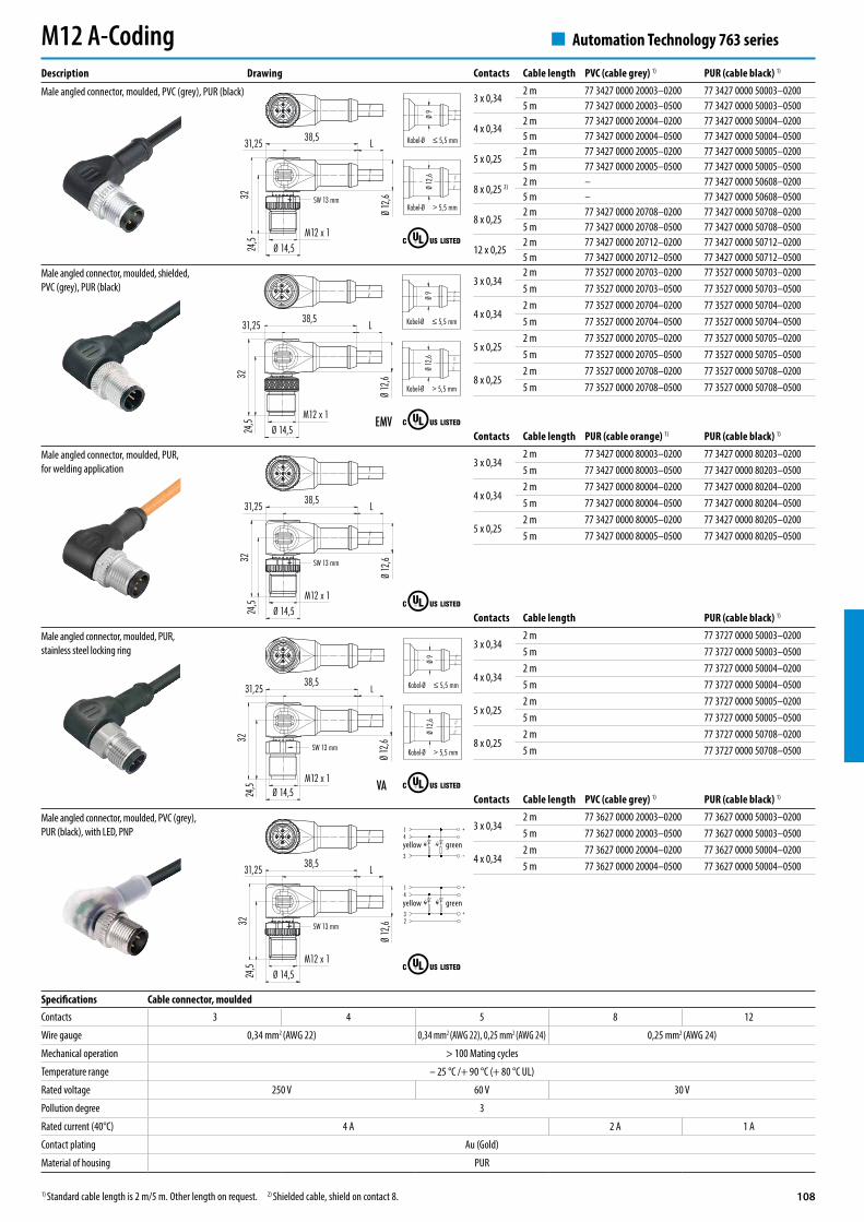
Automation Technology 763 series
Description Drawing
Male angled connector, moulded, PVC (grey), PUR (black)
Male angled connector, moulded, PUR, for welding application
Male angled connector, moulded, PUR, stainless steel locking ring
Male angled connector, moulded, PVC (grey), PUR (black), with LED, PNP
Male angled connector, moulded, shielded, PVC (grey), PUR (black)
M12 A-Coding
1) Standard cable length is 2 m/5 m. Other length on request. 2) Shielded cable, shield on contact 8.
Contacts Cable length PVC (cable grey) 1) PUR (cable black) 1)
3 x 0,342 m 77 3427 0000 20003–0200 77 3427 0000 50003–02005 m 77 3427 0000 20003–0500 77 3427 0000 50003–0500
4 x 0,342 m 77 3427 0000 20004–0200 77 3427 0000 50004–02005 m 77 3427 0000 20004–0500 77 3427 0000 50004–0500
5 x 0,252 m 77 3427 0000 20005–0200 77 3427 0000 50005–02005 m 77 3427 0000 20005–0500 77 3427 0000 50005–0500
8 x 0,25 2) 2 m – 77 3427 0000 50608–02005 m – 77 3427 0000 50608–0500
8 x 0,252 m 77 3427 0000 20708–0200 77 3427 0000 50708–02005 m 77 3427 0000 20708–0500 77 3427 0000 50708–0500
12 x 0,252 m 77 3427 0000 20712–0200 77 3427 0000 50712–02005 m 77 3427 0000 20712–0500 77 3427 0000 50712–0500
Contacts Cable length PVC (cable grey) 1) PUR (cable black) 1)
3 x 0,342 m 77 3627 0000 20003–0200 77 3627 0000 50003–02005 m 77 3627 0000 20003–0500 77 3627 0000 50003–0500
4 x 0,342 m 77 3627 0000 20004–0200 77 3627 0000 50004–02005 m 77 3627 0000 20004–0500 77 3627 0000 50004–0500
Contacts Cable length PUR (cable orange) 1) PUR (cable black) 1)
3 x 0,342 m 77 3427 0000 80003–0200 77 3427 0000 80203–02005 m 77 3427 0000 80003–0500 77 3427 0000 80203–0500
4 x 0,342 m 77 3427 0000 80004–0200 77 3427 0000 80204–02005 m 77 3427 0000 80004–0500 77 3427 0000 80204–0500
5 x 0,252 m 77 3427 0000 80005–0200 77 3427 0000 80205–02005 m 77 3427 0000 80005–0500 77 3427 0000 80205–0500
Specifications Cable connector, mouldedContacts 3 4 5 8 12
Wire gauge 0,34 mm2 (AWG 22) 0,34 mm2 (AWG 22), 0,25 mm2 (AWG 24) 0,25 mm2 (AWG 24)
Mechanical operation > 100 Mating cycles
Temperature range – 25 °C /+ 90 °C (+ 80 °C UL)
Rated voltage 250 V 60 V 30 V
Pollution degree 3
Rated current (40°C) 4 A 2 A 1 A
Contact plating Au (Gold)
Material of housing PUR
yellow green
yellow green
Contacts Cable length PUR (cable black) 1)
3 x 0,342 m 77 3727 0000 50003–02005 m 77 3727 0000 50003–0500
4 x 0,342 m 77 3727 0000 50004–02005 m 77 3727 0000 50004–0500
5 x 0,252 m 77 3727 0000 50005–02005 m 77 3727 0000 50005–0500
8 x 0,252 m 77 3727 0000 50708–02005 m 77 3727 0000 50708–0500
109
44–6 mm 99 0430 82 046–8 mm 99 0430 282 04
54–6 mm 99 0436 82 056–8 mm 99 0436 282 05
8 6–8 mm 99 0486 282 08
4 4–6 mm 99 0530 14 04
~54
Ø 20
M12 x
1
SW 18mm
Ø 20
,2M1
2 x 1
SW 18mm SW 14mm SW 13mm
~57
Ø 20
,2M1
2 x 1
SW 18mm SW 14mm SW 13mm
~57
~54
Ø 20
M12 x
1
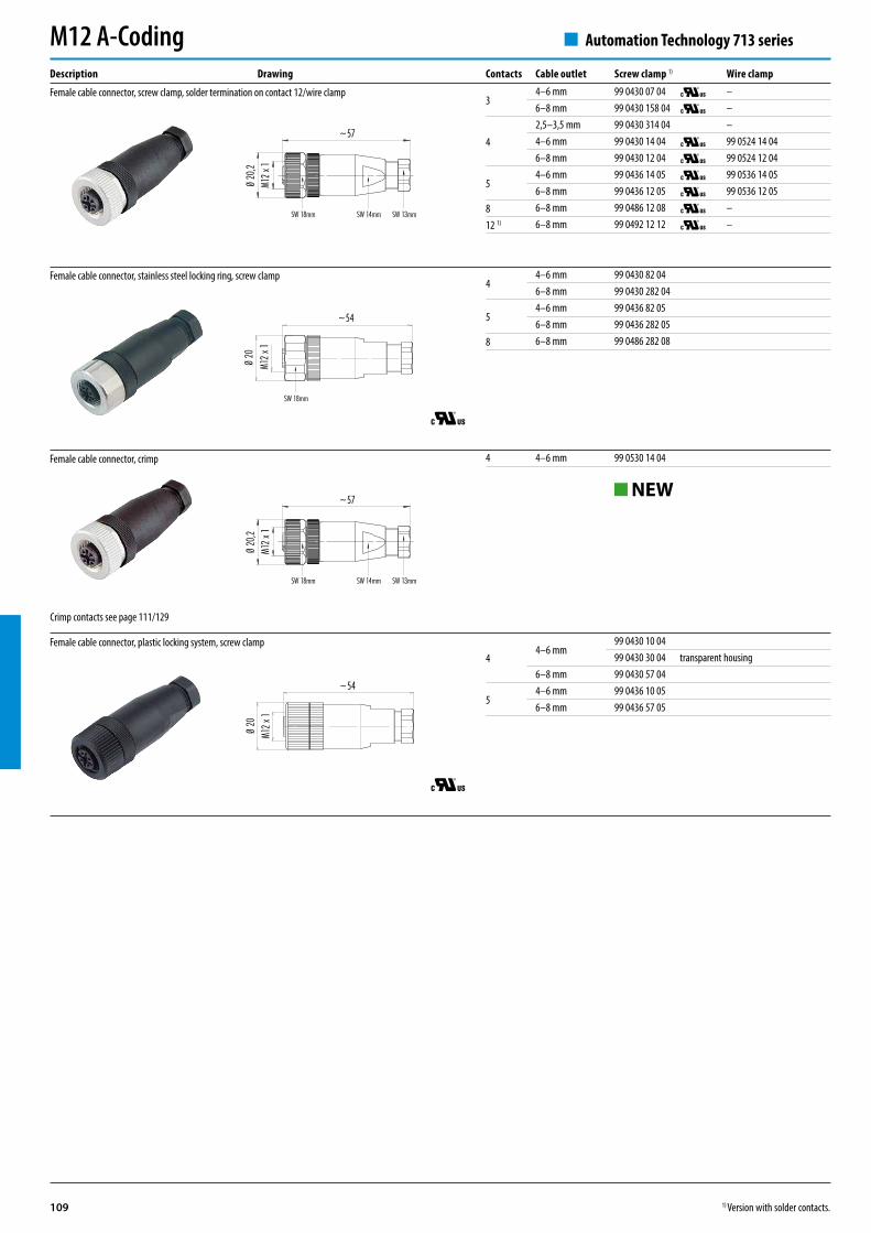
Automation Technology 713 series
Description Drawing
Female cable connector, screw clamp, solder termination on contact 12/wire clamp
Female cable connector, stainless steel locking ring, screw clamp
Female cable connector, plastic locking system, screw clamp
Female cable connector, crimp
M12 A-CodingContacts Cable outlet Screw clamp 1) Wire clamp
34–6 mm 99 0430 07 04 –6–8 mm 99 0430 158 04 –
4
2,5–3,5 mm 99 0430 314 04 –4–6 mm 99 0430 14 04 99 0524 14 046–8 mm 99 0430 12 04 99 0524 12 04
54–6 mm 99 0436 14 05 99 0536 14 056–8 mm 99 0436 12 05 99 0536 12 05
8 6–8 mm 99 0486 12 08 –
12 1) 6–8 mm 99 0492 12 12 –
Crimp contacts see page 111/129
44–6 mm
99 0430 10 0499 0430 30 04 transparent housing
6–8 mm 99 0430 57 04
54–6 mm 99 0436 10 056–8 mm 99 0436 57 05
NEW
1) Version with solder contacts.
110
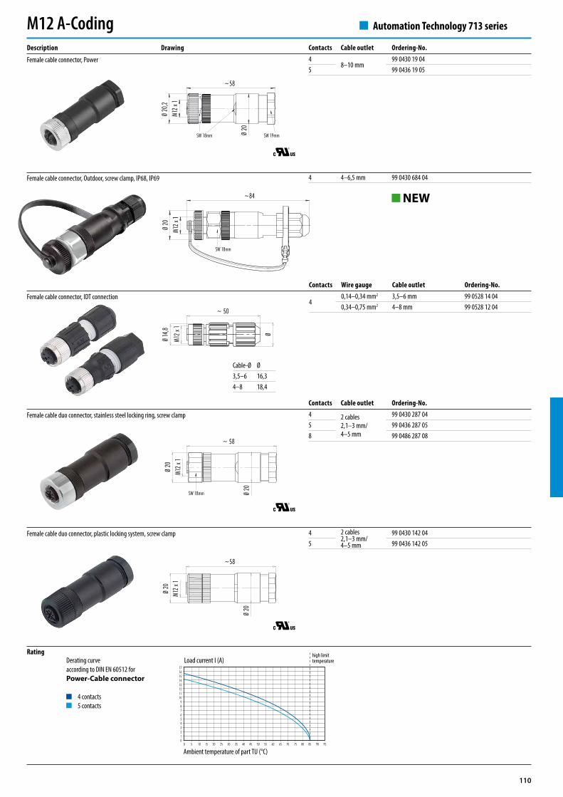
4 4–6,5 mm 99 0430 684 04
~58
Ø 20
M12 x
1
Ø 20
M12 x
1
Ø 20
~ 58
Ø 20
SW 18mm
M12 x
1Ø
20
SW 18mm
~84
~ 50
Ø
Ø 14
,8
M12 x
1M1
2 x 1
Ø 20
,2
~58
Ø 20
SW 18mm SW 19mm
17161514131211109876543210
0 5 10 15 20 25 30 35 40 45 50 55 60 65 70 75 80 85 90 95
Contacts Cable outlet Ordering-No.4
8–10 mm99 0430 19 04
5 99 0436 19 05
Contacts Cable outlet Ordering-No.4 2 cables
2,1–3 mm/4–5 mm
99 0430 287 045 99 0436 287 058 99 0486 287 08
Automation Technology 713 series
Description Drawing
Female cable connector, Power
Female cable connector, Outdoor, screw clamp, IP68, IP69
Female cable connector, IDT connection
Female cable duo connector, stainless steel locking ring, screw clamp
Female cable duo connector, plastic locking system, screw clamp
M12 A-Coding
Cable-Ø Ø3,5–6 16,34–8 18,4
Contacts Wire gauge Cable outlet Ordering-No.
40,14–0,34 mm2 3,5–6 mm 99 0528 14 040,34–0,75 mm2 4–8 mm 99 0528 12 04
RatingDerating curve according to DIN EN 60512 for Power-Cable connector
4 contacts5 contacts
Load current I (A)
Ambient temperature of part TU (°C)
4 2 cables2,1–3 mm/4–5 mm
99 0430 142 045 99 0436 142 05
NEW
high limit temperature

111
4 5–8 mm 99 1432 814 04 99 1528 814 045 5–8 mm 99 1438 814 05 99 1540 814 05
85–8 mm 99 1488 814 08 –8–9 mm 99 1488 812 08 –
43–5,5 mm 99 1430 991 045,5–8,6 mm 99 1430 992 04
53–5,5 mm 99 1436 991 055,5–8,6 mm 99 1436 992 05
8 5,5–8,6 mm 99 1486 992 08
4 5–8 mm 99 1434 814 04
SW 16mm SW 13mm/SW 16mm
~57
Ø 20
M12 x
1
SW 18mm
~65
M12 x
1Ø
20
SW 18mm SW 16mm SW 13mm/SW 15mm
M12 x
1Ø 2
0
~57
SW 19mm SW 19mm
~65
M12 x
1Ø
20
SW 18mm SW 16mm SW 13mm
Ø 1,8 10,9 1,6
17,3
Ø 3,2
Automation Technology 713 series
Description Drawing
Female cable connector, screw clamp/wire clamp, with shielding ring, shieldable, solder termination on contact 12
Female cable connector, screw clamp/wire clamp, iris type spring, shieldable
Female cable connector, crimp, shieldable
Female contact, PU 100 pieces
Female cable connector, screw clamp, with shielding ring, stainless steel version, shieldable
M12 A-CodingContacts Cable outlet Screw clamp 1) Wire clamp
44–6 mm 99 1430 814 04 99 1526 814 046–8 mm 99 1430 812 04 99 1526 812 04
54–6 mm 99 1436 814 05 99 1538 814 056–8 mm 99 1436 812 05 99 1538 812 05
86–8 mm 99 1486 812 08 –8–10 mm 99 1486 914 08 –
12 1) 6–8 mm 99 1492 812 12 –
Crimp contacts see page 111/129 Wire gauge AWG Ordering-No.0,14 mm2 – 0,34 mm2 26–22 61 1227 1460,34 mm2 – 0,5 mm2 22–20 61 1155 1460,75 mm2 – 1,0 mm2 18–16 61 1228 1461,0 mm2 – 1,5 mm2 16 61 1229 146
NEW
NEW
1) Version with solder contacts.

112
44–6 mm 99 0430 92 046–8 mm 99 0430 292 04
54–6 mm 99 0436 92 056–8 mm 99 0436 292 05
48–10 mm
99 0430 58 045 99 0436 58 05
~40
M12 x 1Ø 20
~38
SW 18mm
Ø 20,2M12 x 1
~38
~40
SW 18mm
M12 x 1Ø 20
38
Ø 14
,8
~39
M12 x 1Ø 20,2
SW 18mm
SW 19mm45°
20~
38
~56
M12 x 1
Ø 18
SW 18mm
45°
SW 13mm/SW 16mm
45°
~37
20
~64
M12 x 1
SW 18mm SW 13mm
4 5–8 mm 99 1432 824 04 99 1528 824 045 5–8 mm 99 1438 824 05 99 1540 824 05
Automation Technology 713 series
Description Drawing
M12 A-Coding
Female angled connector, screw clamp, solder termination on contact 12/wire clamp
Female angled connector, stainless steel locking ring, screw clamp
Female angled connector, plastic locking system, screw clamp
Female angled connector, Power
Contacts Cable outlet Screw clamp 1) Wire clamp
34–6 mm 99 0430 27 04 –6–8 mm 99 0430 161 04 –
4
2,5–3,5 mm 99 0430 324 04 –4–6 mm 99 0430 24 04 99 0524 24 046–8 mm 99 0430 52 04 99 0524 52 04
54–6 mm 99 0436 24 05 99 0536 24 056–8 mm 99 0436 52 05 99 0536 52 05
12 1) 6–8 mm 99 0492 52 12 –
It is possible to turn and fix the contact carrier in 4 different 90° positions
Female angled connector, screw clamp/wire clamp, iris type spring, shieldable
Female angled connector, screw clamp/wire clamp, with shielding ring, shieldable, solder termination on contact 12
Contacts Cable outlet Screw clamp 1) Wire clamp
44–6 mm 99 1430 824 04 99 1526 824 046–8 mm 99 1430 822 04 99 1526 822 04
54–6 mm 99 1436 824 05 99 1538 824 056–8 mm 99 1436 822 05 99 1538 822 05
12 1) 6–8 mm 99 1492 822 12 –
It is possible to turn and fix the contact carrier in 4 different 90° positions
It is possible to turn and fix the contact carrier in 4 different 90° positions
44–6 mm
99 0430 00 0499 0430 20 04 transparent housing
6–8 mm99 0430 69 0499 0430 68 04 transparent housing
54–6 mm 99 0436 00 056–8 mm 99 0436 69 05
1) Version with solder contacts.
113
Ø 14
,5
43,931
L
Ø 14
,5M1
2 x 1
SW 13mm
Kabel-Ø ≤ 5,5 mm Kabel-Ø > 5,5 mm
Ø 9
Ø 12
,6
Ø 14
,5
43,931
L
Ø 14
,5M1
2 x 1
SW 13mm
Kabel-Ø ≤ 5,5 mm Kabel-Ø > 5,5 mm
Ø 9
Ø 12
,6
Kabel-Ø ≤ 5,5 mm Kabel-Ø > 5,5 mm
Ø 9
Ø 12
,6
Ø 14
,5
43,931
L
Ø 14
,5M1
2 x 1
VASW 13mm
Ø 14
,5M1
2 x 1 43,9 L
Ø 14
,5
31
EMV
Kabel-Ø ≤ 5,5 mm Kabel-Ø > 5,5 mm
Ø 9
Ø 12
,6
Ø 14
,5
43,931
L
Ø 14
,5M1
2 x 1
SW 13mm
3 x 0,342 m 77 3530 0000 20703–0200 77 3530 0000 50703–02005 m 77 3530 0000 20703–0500 77 3530 0000 50703–0500
4 x 0,342 m 77 3530 0000 20704–0200 77 3530 0000 50704–02005 m 77 3530 0000 20704–0500 77 3530 0000 50704–0500
5 x 0,252 m 77 3530 0000 20705–0200 77 3530 0000 50705–02005 m 77 3530 0000 20705–0500 77 3530 0000 50705–0500
8 x 0,252 m 77 3530 0000 20708–0200 77 3530 0000 50708–02005 m 77 3530 0000 20708–0500 77 3530 0000 50708–0500
+14
–3
+14
+32
Ø 14
,5
43,931
L
Ø 14
,5M1
2 x 1
SW 13mm
Automation Technology 763 series
Description Drawing
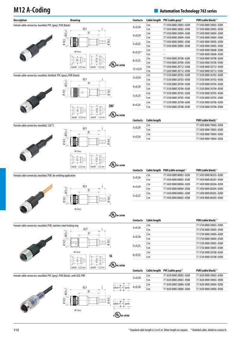
Female cable connector, moulded, PVC (grey), PUR (black)
Female cable connector, moulded, 120 °C
Female cable connector, moulded, PUR, for welding application
Female cable connector, moulded, PUR, stainless steel locking ring
Female cable connector, moulded, PVC (grey), PUR (black), with LED, PNP
Female cable connector, moulded, shielded, PVC (grey), PUR (black)
M12 A-Coding
1) Standard cable length is 2 m/5 m. Other length on request. 2) Shielded cable, shield on contact 8.
Contacts Cable length PVC (cable grey) 1) PUR (cable black) 1)
3 x 0,342 m 77 3430 0000 20003–0200 77 3430 0000 50003–02005 m 77 3430 0000 20003–0500 77 3430 0000 50003–0500
4 x 0,342 m 77 3430 0000 20004–0200 77 3430 0000 50004–02005 m 77 3430 0000 20004–0500 77 3430 0000 50004–0500
5 x 0,252 m 77 3430 0000 20005–0200 77 3430 0000 50005–02005 m 77 3430 0000 20005–0500 77 3430 0000 50005–0500
8 x 0,25 2) 2 m – 77 3430 0000 50608–02005 m – 77 3430 0000 50608–0500
8 x 0,252 m 77 3430 0000 20708–0200 77 3430 0000 50708–02005 m 77 3430 0000 20708–0500 77 3430 0000 50708–0500
12 x 0,252 m 77 3430 0000 20712–0200 77 3430 0000 50712–02005 m 77 3430 0000 20712–0500 77 3430 0000 50712–0500
Contacts Cable length PUR (cable black) 1)
3 x 0,342 m 77 3430 0000 70003–02005 m 77 3430 0000 70003–0500
4 x 0,342 m 77 3430 0000 70004–02005 m 77 3430 0000 70004–0500
Contacts Cable length PVC (cable grey) 1) PUR (cable black) 1)
3 x 0,342 m 77 3630 0000 20003–0200 77 3630 0000 50003–02005 m 77 3630 0000 20003–0500 77 3630 0000 50003–0500
4 x 0,342 m 77 3630 0000 20004–0200 77 3630 0000 50004–02005 m 77 3630 0000 20004–0500 77 3630 0000 50004–0500yellow green
yellow green
Contacts Cable length PUR (cable orange) 1) PUR (cable black) 1)
3 x 0,342 m 77 3430 0000 80003–0200 77 3430 0000 80203–02005 m 77 3430 0000 80003–0500 77 3430 0000 80203–0500
4 x 0,342 m 77 3430 0000 80004–0200 77 3430 0000 80204–02005 m 77 3430 0000 80004–0500 77 3430 0000 80204–0500
5 x 0,252 m 77 3430 0000 80005–0200 77 3430 0000 80205–02005 m 77 3430 0000 80005–0500 77 3430 0000 80205–0500
Contacts Cable length PUR (cable black) 1)
3 x 0,342 m 77 3730 0000 50003–02005 m 77 3730 0000 50003–0500
4 x 0,342 m 77 3730 0000 50004–02005 m 77 3730 0000 50004–0500
5 x 0,252 m 77 3730 0000 50005–02005 m 77 3730 0000 50005–0500
8 x 0,252 m 77 3730 0000 50708–02005 m 77 3730 0000 50708–0500

114
Ø 14
,5
M12 x
1Ø
14,5
43,930,9
L
SW 13mm
Ø 14
,5
43,930,9
Ø 14
,5M1
2 x 1
SW 13mm
5 – 77 9840 0000 00005
Automation Technology 763 series
Description Drawing
Female cable connector, CAN-Bus
Female terminating connector, CAN-Bus
M12 A-Coding
1) Standard-Cable length 2 m/5 m/10 m. Other length on request.
Contacts Cable length Ordering-No. 1)
52 m 77 2530 0000 50705–02005 m 77 2530 0000 50705–050010 m 77 2530 0000 50705–1000
Pin assignment
1 not assembled2 not assembled3 not assembled4 Resistor5 120 Ω
Contacts 3 4 5 8 12
Wire gauge 3 x 0,34 mm2 (AWG 22) 4 x 0,34 mm2 (AWG 22) 5 x 0,34 mm2 (AWG 24) 8 x 0,25 mm2 (AWG 24) 12 x 0,25 mm2 (AWG 24)
Material jacket PVC PUR PVC PUR PVC PUR PVC PUR PVC PUR
Insulation of wire PVC PP PVC PP PVC PP PVC PP PVC PP
Design of wire (mm) 32 x 0,1
Cable diameter (mm) 4,5 4,3 4,8 4,7 4,8 4,7 6 6,6 6,5
Temperature range cable in move PVC: – 5 °C /+ 105 °C PUR: – 25 °C /+ 90 °C (in chain flex application + 60 °C)
Temperature range cable fixed PVC: – 40 °C /+ 105 °C PUR: – 50 °C /+ 90 °C
Bending radius (at 10 x D) 2 Mio. 5 Mio. 2 Mio. 5 Mio. 2 Mio. 5 Mio. 2 Mio.
Approval UL/CSA
UL-style PVC: AWM 2517 PUR: AWM 20549
Chain flex application bending radius min. 10 x D, permitted acceleration 5 m/s2
Specifications Standard Cable
Contacts 3 4 5 8
Wire gauge 3 x 0,34 mm2 (AWG 22) 4 x 0,34 mm2 (AWG 22) 5 x 0,25 mm2 (AWG 24) 8 x 0,25 mm2 (AWG 24)
Material jacket PVC PUR PVC PUR PVC PUR PVC PUR
Insulation of wire PVC PP PVC PP PVC PP PVC PP
Design of wire (mm) 42 x 0,1 32 x 0,1
Cable diameter (mm) 5 4,6 5,4 4,7 5,7 4,8 6,8 6
Temperature range cable in move PVC: – 5 °C /+ 105 °C PUR: – 25 °C /+ 90 °C (in chain flex application + 60 °C)
Temperature range cable fixed PVC: – 20 °C /+ 105 °C PUR: – 50 °C /+80 °C PVC: – 40 °C /+ 105 °C PUR: – 50 °C /+80 °C
Bending radius (at 10 x D) 2 Mio.
Approval UL/CSA
Cover screen grid 85 %
Chain flex application bending radius min. 10 x D, permitted acceleration 5 m/s2
Contacts 5
Wire gauge 1 x 2 x AWG 22 and 1 x 2 x AWG 24
Material jacket PUR
Insulation of wire Polyolefine
Design of wire (mm) 19 x 0,16/19 x 0,13
Cable diameter (mm) 7,2
UL-style AWM 1581, AWM 444
Specifications Shielded cable
Specifications CAN-Bus Cable

115
Ø 12
,6
38,531,2 L
Ø 14,5M12 x 1
27,5
20 VA
Kabel-Ø ≤ 5,5 mm
Kabel-Ø > 5,5 mm
Ø 9
Ø 12
,6
Ø 12
,6
38,531,2 L
Ø 14,5M12 x 1
27,5
20 EMV
Kabel-Ø ≤ 5,5 mm
Kabel-Ø > 5,5 mm
Ø 9
Ø 12
,6
Ø 12
,6
38,531,2 L
Ø 14,5M12 x 1
27,5
20
SW 13 mm
Kabel-Ø ≤ 5,5 mm
Kabel-Ø > 5,5 mm
Ø 9
Ø 12
,6
Ø 12
,6
38,531,2 L
Ø 14,5M12 x 1
27,5
20
SW 13 mm
Kabel-Ø ≤ 5,5 mm
Kabel-Ø > 5,5 mm
Ø 9
Ø 12
,6
3 x 0,342 m 77 3534 0000 20703–0200 77 3534 0000 50703–02005 m 77 3534 0000 20703–0500 77 3534 0000 50703–0500
4 x 0,342 m 77 3534 0000 20704–0200 77 3534 0000 50704–02005 m 77 3534 0000 20704–0500 77 3534 0000 50704–0500
5 x 0,252 m 77 3534 0000 20705–0200 77 3534 0000 50705–02005 m 77 3534 0000 20705–0500 77 3534 0000 50705–0500
8 x 0,252 m 77 3534 0000 20708–0200 77 3534 0000 50708–02005 m 77 3534 0000 20708–0500 77 3534 0000 50708–0500
Ø 12
,6
38,531,2 L
Ø 14,5M12 x 1
27,5
20
SW 13 mm
Ø 12
,6
38,531,2 L
Ø 14,5M12 x 1
27,5
20
SW 13 mm
+14
–3
+14
+32
Automation Technology 763 series
Description Drawing
Female angled connector, moulded, PVC (grey), PUR (black)
Female angled connector, moulded, PUR, for welding application
Female angled connector, moulded, 120 °C
Female angled connector, moulded, PUR, stainless steel locking ring
Female angled connector, moulded, PVC (grey), PUR (black), with LED, PNP
Female angled connector, moulded, shielded, PVC (grey), PUR (black)
M12 A-Coding
1) Standard cable length is 2 m/5 m. Other length on request. 2) Shielded cable, shield on contact 8.
Contacts Cable length PVC (cable grey) 1) PUR (cable black) 1)
3 x 0,342 m 77 3434 0000 20003–0200 77 3434 0000 50003–02005 m 77 3434 0000 20003–0500 77 3434 0000 50003–0500
4 x 0,342 m 77 3434 0000 20004–0200 77 3434 0000 50004–02005 m 77 3434 0000 20004–0500 77 3434 0000 50004–0500
5 x 0,252 m 77 3434 0000 20005–0200 77 3434 0000 50005–02005 m 77 3434 0000 20005–0500 77 3434 0000 50005–0500
8 x 0,25 2) 2 m – 77 3434 0000 50608–02005 m – 77 3434 0000 50608–0500
8 x 0,252 m 77 3434 0000 20708–0200 77 3434 0000 50708–02005 m 77 3434 0000 20708–0500 77 3434 0000 50708–0500
12 x 0,252 m 77 3434 0000 20712–0200 77 3434 0000 50712–02005 m 77 3434 0000 20712–0500 77 3434 0000 50712–0500
Contacts Cable length PVC (cable grey) 1) PUR (cable black) 1)
3 x 0,342 m 77 3634 0000 20003–0200 77 3634 0000 50003–02005 m 77 3634 0000 20003–0500 77 3634 0000 50003–0500
4 x 0,342 m 77 3634 0000 20004–0200 77 3634 0000 50004–02005 m 77 3634 0000 20004–0500 77 3634 0000 50004–0500
yellow green
yellow green
Contacts Cable length PUR (cable black) 1)
3 x 0,342 m 77 3434 0000 70003–02005 m 77 3434 0000 70003–0500
4 x 0,342 m 77 3434 0000 70004–02005 m 77 3434 0000 70004–0500
Contacts Cable length PUR (cable orange) 1) PUR (cable black) 1)
3 x 0,342 m 77 3434 0000 80003–0200 77 3434 0000 80203–02005 m 77 3434 0000 80003–0500 77 3434 0000 80203–0500
4 x 0,342 m 77 3434 0000 80004–0200 77 3434 0000 80204–02005 m 77 3434 0000 80004–0500 77 3434 0000 80204–0500
5 x 0,252 m 77 3434 0000 80005–0200 77 3434 0000 80205–02005 m 77 3434 0000 80005–0500 77 3434 0000 80205–0500
Contacts Cable length PUR (cable black) 1)
3 x 0,34
2 m 77 3734 0000 50003–02005 m 77 3734 0000 50003–05002 m LED, PNP 77 3834 0000 50003–02005 m LED, PNP 77 3834 0000 50003–0500
4 x 0,342 m 77 3734 0000 50004–02005 m 77 3734 0000 50004–0500
5 x 0,252 m 77 3734 0000 50005–02005 m 77 3734 0000 50005–0500
8 x 0,252 m 77 3734 0000 50708–02005 m 77 3734 0000 50708–0500
Top Related