


Languages
Pages
Legal

Merlin Gerin Modicon Square D Telemecanique
Catalogue
LV power air circuit-breakersand switch-disconnectors
Masterpact Merlin Gerin52
387
Sans titre-1 21/12/01, 9:261

As standards, specifications and designs change from time to time, please ask for confirmationof the information given in this publication.
5, rue Nadar92506 Rueil-Malmaison CedexFrance
Tel: +33 (0)1 41 29 82 00Fax:+33 (0)1 47 51 80 20
http://www.schneiderelectric.com
Schneider Electric SA
ce document a été imprimé sur du papier écologique.
0000
000
© 1
996
Sch
neid
er E
lect
ric S
A -
All
right
res
erve
d
0000 000 12-96
This document has been printed on ecological paper.
Created by:Photos: SchneiderPrinting by:
Sans titre-1 21/12/01, 9:262
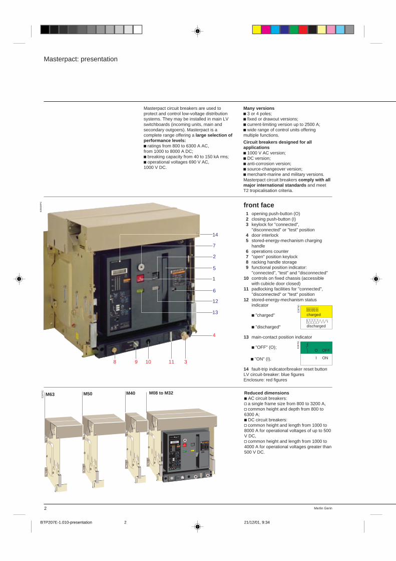
front face1 opening push-button (O)2 closing push-button (I)3 keylock for "connected",
"disconnected" or "test" position4 door interlock5 stored-energy-mechanism charging
handle6 operations counter7 "open" position keylock8 racking handle storage9 functional position indicator:
"connected", "test" and "disconnected"10 controls on fixed chassis (accessible
with cubicle door closed)11 padlocking facilities for "connected",
"disconnected" or "test" position12 stored-energy-mechanism status
indicator
c "charged"
c "discharged"
13 main-contact position indicator
c "OFF" (O);
c "ON" (I).
14 fault-trip indicator/breaker reset buttonLV circuit-breaker: blue figuresEnclosure: red figures
Masterpact: presentation
Masterpact circuit breakers are used toprotect and control low-voltage distributionsystems. They may be installed in main LVswitchboards (incoming units, main andsecondary outgoers). Masterpact is acomplete range offering a large selection ofperformance levels:c ratings from 800 to 6300 A AC,from 1000 to 8000 A DC;c breaking capacity from 40 to 150 kA rms;c operational voltages 690 V AC,1000 V DC.
2 Merlin Gerin
Many versionsc 3 or 4 poles;c fixed or drawout versions;c current-limiting version up to 2500 A;c wide range of control units offeringmultiple functions.
Circuit breakers designed for allapplicationsc 1000 V AC version;c DC version;c anti-corrosion version;c source-changeover version;c merchant-marine and military versions.Masterpact circuit breakers comply with allmajor international standards and meetT2 tropicalisation criteria.
Reduced dimensionsc AC circuit breakers:v a single frame size from 800 to 3200 A,v common height and depth from 800 to6300 A;c DC circuit breakers:v common height and length from 1000 to8000 A for operational voltages of up to 500V DC,v common height and length from 1000 to4000 A for operational voltages greater than500 V DC.
push to reset
I
I1 I2 I3
90%
50%
20%
STR 58 UE
0.63Io
Ir
0.8
0.5 1
xIn
90
105%Ir
.88.9 .92
.95
.981.8
.85
xIo
Im tm
3
4 56
8
101.52
xIo
.3
.4 .3
.1
.1.2
on I2t off
.2
0
Ir fault
tr
Im fault
tm
I
faultIh
th
t
i
test
+ S –
– T +
T
F
Ihth
400
500 600800
1000
1200250
320
A
.3
.4 .4
.2
.1.2
on I2t off
.3
.1
I
off2
xIn
Ir :
Im :
th :
I
IG LI
G
LLG
LIG
off
reset V
tr
60
120 240
480
1530
at 1,5Ir
4
6
8 12
17
22
Ic1Ic2
.86
.9 .93.95
.98
1.8
.85
.7
.8 .85
.95
.5.6
xIr
.9
1
R
xIr
test
Opush OFF
connected
test
disconnected
O OFFdischarged
I
push ON
MERLIN GERIN
M32 H1masterpact
IEC 947-2
00000
Ui
Ue
Icu
Ics
Icw
1000V
380/440V
100kA
100kA
75kA 1s
50/60Hz
480/690V
85kA
85kA
M63 M50 M40 M08 à M32
charged
discharged
O OFF
I ON
E28
791
E28
761
E28
760
M08 to M32
0359
28P
C
11
14
7
2
5
1
6
12
13
4
39 108
BTP207E-1.010-presentation 21/12/01, 9:342
3Merlin Gerin
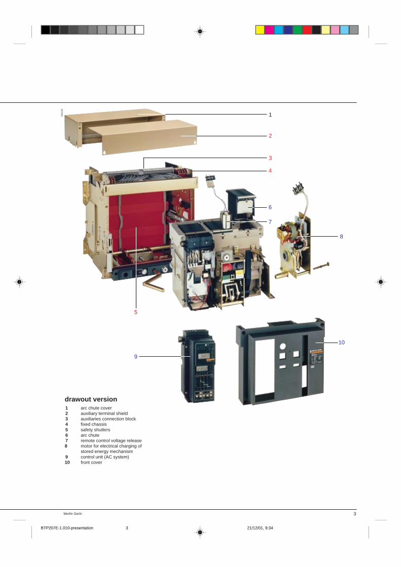
drawout version1 arc chute cover2 auxiliary terminal shield3 auxiliaries connection block4 fixed chassis5 safety shutters6 arc chute7 remote control voltage release8 motor for electrical charging of
stored energy mechanism9 control unit (AC system)10 front cover
1
2
3
6
7
8
10
9
5
4
0151
59
BTP207E-1.010-presentation 21/12/01, 9:343
Merlin Gerin4
Automatic source-changeover controller
Fixed circuit breaker
50%
20%
STR 58 U
0.63Io Ir tr
0.8
0.5 1
xIn
90
105
τ tr
%Ir
.88.9 .92
.95
.981.8
.85
xIo
60120 240
480
1530
at 1.5Ir
Im tm
3
4 56
8
101.52
xIr
.3
.4 .3
.1
.1.2
on I2t off
.2
0
Ir fault
tr
Im fault
tm
I
faultIh
th
i
test
+ –
– +
T
R
test
Ih 1200A Max th
400500 600
800
1000
1200250320
A
.3
.4 .4
.2
.1.2
on I2t off
.3
.1
I
8
12 1419
22
Max.24
xIn
Ic1 Ic2
.86
.9 .93.95
.98
1.8.85
xIr
.7.8 .85
.95
.5.6
.9
1xIr
Ir :
Im :
th :
min.norm
overcurrent
ground
isolation renforcéeclasse II
séparation totaleentre chaque phase
déclencheurs voltmétriquesaccessibles à l'avant
Masterpact: presentation
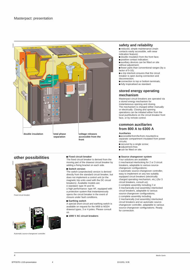
safety and reliabilityc reduced, simple maintenance (maincontacts easily accessible, with wearindication feature);c double insulation from the front face;c positive contact indication;c auxiliary devices can be fitted on sitewithout adjustment;c fewer parts than conventional ranges (by afactor of 5-10);c a trip interlock ensures that the circuitbreaker is open during connection anddisconnection;c connection to top or bottom terminals;c fully tropicalised as standard.
stored energy operatingmechanismMasterpact circuit breakers are operated viaa stored energy mechanism forinstantaneous opening and closing.The mechanism is charged either manuallyor electrically. Closing and openingoperations can be initiated either from thelocal pushbuttons on the circuit breaker frontface, or by remote control.
common auxiliariesfrom 800 A to 6300 AAuxiliariesc accessible from the front, mounted in aseparate compartment insulated from powercircuits;c secured by a single screw;c adjustment-free;c can be fitted on site.
ccccc Source changeover systemFour solutions are available:v mechanical interlocking for 2 or 3 circuitbreakers, adaptable to various source-changeover configurations;v automatic source-changeover controller,easy to implement on any two suitablyequipped circuit breakers (electricallycharged operating mechanism, etc.) (for 3circuit breakers, consult us);v complete assembly including 2 or3 mechanically (rod assembly) interlockedcircuit breakers, adaptable to varioussource-changeover configurations;v complete assembly including2 mechanically (rod assembly) interlockedcircuit breakers and an automatic source-changeover controller, adaptable to varioussource-changeover configurations. Readyfor connection.
other possibilities ccccc Fixed circuit breakerThe fixed circuit breaker is derived from themoving part of the drawout circuit breaker byadding a fixing bracket on each side.
ccccc Switch versionThe switch (unprotected) version is deriveddirectly from the standard circuit breaker, butdoes not implement a control unit (or themagnetic trip units used with the DC circuitbreakers). Available models are:v standard: type HI and NI;v high performance: type HF, equipped witha protection system that instantaneouslyopens the circuit breaker in the event ofclosure under fault conditions.
ccccc Earthing switchA special short-circuit and earthing switch isavailable on request for the M08 to M32Hdrawout types, 3 or 4 poles. Please consultus.
ccccc 1000 V AC circuit breakers
E29
490
voltage releasesaccessible from thefront
total phaseseparation
double insulation
0359
2905
3061
0530
60
0530
58
BTP207E-1.015-presentation 21/12/01, 9:354
Merlin Gerin 5
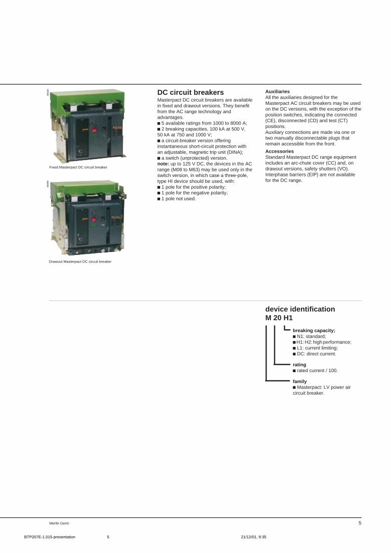
Drawout Masterpact DC circuit breaker
Fixed Masterpact DC circuit breaker
device identificationM 20 H1
breaking capacity;c N1: standard;c H1: H2: high performance;c L1: current limiting;c DC: direct current.
ratingc rated current / 100.
familyc Masterpact: LV power aircircuit breaker.
DC circuit breakersMasterpact DC circuit breakers are availablein fixed and drawout versions. They benefitfrom the AC range technology andadvantages.c 5 available ratings from 1000 to 8000 A;c 2 breaking capacities, 100 kA at 500 V,50 kA at 750 and 1000 V;c a circuit-breaker version offeringinstantaneous short-circuit protection withan adjustable, magnetic trip unit (DINA);c a switch (unprotected) version.note: up to 125 V DC, the devices in the ACrange (M08 to M63) may be used only in theswitch version, in which case a three-pole,type HI device should be used, with:c 1 pole for the positive polarity;c 1 pole for the negative polarity;c 1 pole not used.
AuxiliariesAll the auxiliaries designed for theMasterpact AC circuit breakers may be usedon the DC versions, with the exception of theposition switches, indicating the connected(CE), disconnected (CD) and test (CT)positions.Auxiliary connections are made via one ortwo manually disconnectable plugs thatremain accessible from the front.
AccessoriesStandard Masterpact DC range equipmentincludes an arc-chute cover (CC) and, ondrawout versions, safety shutters (VO).Interphase barriers (EIP) are not availablefor the DC range.
8609
486
096
BTP207E-1.015-presentation 21/12/01, 9:355
Merlin Gerin6
Masterpact: presentation
Masterpact circuit breakers are the productof Merlin Gerin’s vast experience in the fieldof power circuit breakers. They incorporateall the qualities of traditional air circuitbreakers while drawing on certain of theadvantages specific to moulded-case circuitbreakers. In particular, they require nopreventive maintenance.
ease of installationMasterpact is a complete and rationallydesigned range.c 10 ratings;c 4 breaking-capacity levels;c 6 control units;c a complete range of auxiliaries andaccessories;c numerous versions (three and four-poledevices, fixed and drawout versions, etc.).
Masterpact circuit breakers are easy toincorporate in switchboards.c a single frame size from 800 to 3200 A,thus making for standardised columns;c an upper safety clearance equal to zerodue to the arc-chute cover, on both the fixedand drawout versions;c built-in measurement functions in thecontrol units;c auxiliaries are the same for the entirerange and may be easily implemented (onlya screwdriver is required).
Masterpact circuit breakers are easy toconnect to the main distribution system.c all types of connections are available(horizontal and vertical terminals, front andmixed connections);c connections are possible with bars of anythickness;c connection to the input power source ispossible on the upper or lower terminals ofthe circuit breakers.
Due to their small size, Masterpact circuitbreakers can replace most existingcircuit breakers.
continuity of serviceMasterpact circuit breakers are designedwith continuity of service in mind. Theresult is:c total time discrimination on the N1 and H1circuit breakers and maximum discriminationon H2 circuit breakers;c factory pre-setting of Masterpact circuitbreakers which never require any periodicmaintenance;c high electrical endurance: 10 000 cycles at1600 A and 30 cycles at 50 kA, withoutmaintenance;c preventive indications: load-sheddingindication switch, long-time thresholdoverrun alarm, etc.;c easy access to the main contacts fittedwith mechanical wear indicators. An optionalfunction on the STR68 control unit is theremote indication of contact wear, thusmaking possible continuous monitoring ofcircuit breakers during their service life.
operating safetyThe insulating casing of Masterpactcircuit breakers provides for:c user safety:v double insulation on the front face(class II),v auxiliary circuits in a compartmentinsulated from the power circuits;c switchboard safety when the circuitbreaker is in the open position:v each pole is effectively isolated in its ownhousing,v limitation of external disturbances.Positive contact indicationThe position indicator cannot indicate«open» unless the poles are effectivelyseparated by the required distance.The circuit breakers automatically openduring racking in and out .
reliabilityc Masterpact circuit breakers comprise tentimes fewer parts than traditional devices.They are easier to produce and morereliable.c the Masterpact circuit-breaker factory iscertified ISO 9002;c the design of Masterpact circuit breakersis modular with delayed differentiation(highest possible number of common partson all models). The result is shorter deliverytimes and enhanced reliability.
,
0366
3402
5179
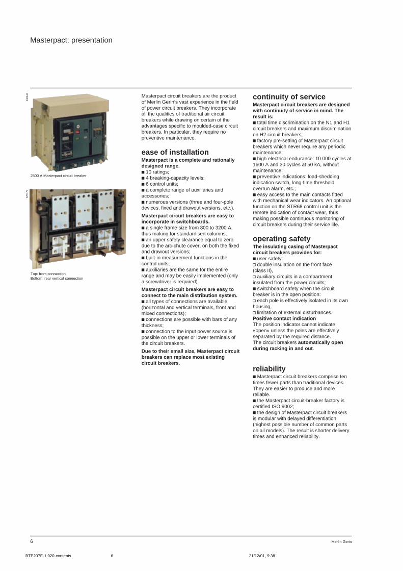
2500 A Masterpact circuit breaker
Top: front connectionBottom: rear vertical connection
BTP207E-1.020-contents 21/12/01, 9:386

7
LV power aircircuit breakers andswitch-disconnectors
Masterpact
2/ functions andcharacteristics
page
generales characteristics 0circuit breaker selection 0switch-disconnectors 0dimensions an weights 0control unit selection 0control unit accessories 0electrical auxiliaries 0mechanical accessories 0source changeover systems 0
BTP207E-2.001-content 21/12/01, 9:397

Merlin Gerin8
MERLIN GERINmasterpactM32 H2Ui 1000V 50/60Hz
Ue 380/440V 480/690V
Icu 100kA 85kA
Ics 100kA 85kA
Icw 75kA 1s
IEC 947-2
Masterpact: functions and characteristics
general characteristics
Standardised characteristics indicated onthe rating plate:Ui: rated insulation voltageUe: rated operational voltageIcu: ultimate breaking capacity, for variousvalues of the rated operational voltage UeIcs: service breaking capacityIcw: short-time withstand current
: suitable for isolation
Masterpact circuit breakers comply with allthe major international standards:c International standard IEC 947-2;c North American standards (please consultus):UL 489, ANSI C37-50, CSA C22-2,NEMA AB1 et SG3;c Japanese standards: JIS 160 and C 8372.
They also comply with the following nationalstandards:c France NF C 63-120;c Germany VDE 0660;c United Kingdom BS 4752;c Australia AS ;c Italy CEI.Masterpact circuit breakers comply with thespecifications of the marine classificationcompanies (Veritas, Lloyd's Register ofShipping, Det Norske Veritas, etc.).
IEC 947-2This standard replaces IEC 157-1,applicable since 1973.The circuit breaker selection criteria areunchanged, but the new standard providesthe user with a better guarantee concerningquality and performance.Circuit breakers are subjected to tests thatare more representative of real operatingconditions.IEC 947-2 also clarifies the notion ofbreaking capacity.c Icu : the ultimate breaking capacity, whichmust be greater than or equal to the 3-phaseshort-circuit current at the point ofinstallation of the circuit breaker, a valueunlikely to be reached under real conditions;c Ics : the service breaking capacity,generally expressed as a percentage of theultimate breaking capacity (25, 50, 75 or100 % of Icu). It corresponds to a short-circuit current that is more likely to bereached under real conditions. The circuitbreaker must continue to operate normallyafter having interrupted a current equal toIcs several times;c Icw : short-time withstand current forcircuit breakers belonging to category B(category B refers to circuit breakers withtime discrimination and category A to thosewithout time discrimination).Furthermore, IEC 947-2 takes into accountrecent technological advances:c suitability for isolation recognised forcircuit breakers having passed specialelectrical and mechanical tests;c industrial earth-fault circuit breakerscovered by an appendix;c definition of tests designed to ensurecoordination between two circuit breakers.
conformity with standards
tropicalisationAs standard, Masterpact circuit breakerscomply with NF C 63-100 standard level 2conditions (95 % relative humidity at 45 °Cor 80 % at 55 °C, hot and humid climateconditions). They also comply with thefollowing standards:c IEC 68-2-30 damp heat;c IEC 68-2-2 dry heat;c IEC 68-2-11 salt spray;c IEC 68-2-1 low temperatures during
storage.Corrosive atmospheres: Special grease orother surface coatings available (pleaseconsult us).
pollution degreeMasterpact circuit breakers are certified foroperation in pollution degree IVenvironments as defined byIEC standard 947 (industrial environments).
E29
049
BTP207E-2.020-gen. charact.. 21/12/01, 9:408
9Merlin Gerin
positive contact indicationAll Masterpact circuit breakers offer positivecontact indication. The toggle positionrigorously reflects the position of the maincontacts. It can indicate the "OFF" positiononly if the contacts are effectively open anda suitable distance apart.
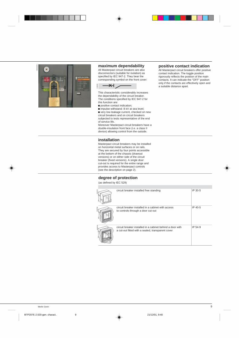
degree of protection(as defined by IEC 529)
circuit breaker installed free standing IP 30-5
circuit breaker installed in a cabinet with access IP 40-5to controls through a door cut-out
circuit breaker installed in a cabinet behind a door with IP 54-9a cut-out fitted with a sealed, transparent cover
installationMasterpact circuit breakers may be installedon horizontal metal surfaces or on rails.They are secured by four points accessibleat the bottom of the chassis (drawoutversions) or on either side of the circuitbreaker (fixed versions). A single doorcut-out is required for the entire range andprovides access to Masterpact controls(see the description on page 2)..
0359
32R
C
E28
757
E28
758
E28
763
maximum dependabilityAll Masterpact circuit breakers are alsodisconnectors (suitable for isolation) asspecified by IEC 947-2. They bear thecorresponding symbol on the front cover:
This characteristic considerably increasesthe dependability of the circuit breaker.The conditions specified by IEC 947-2 forthis function are:c positive contact indication;c impulse withstand: 8 kV at sea level;c very low leakage current, checked on newcircuit breakers and on circuit breakerssubjected to tests representative of the endof service life.Moreover Masterpact circuit breakers have adouble-insulation front face (i.e. a class IIdevice) allowing control from the outside.
E18
569
BTP207E-2.020-gen. charact.. 21/12/01, 9:409
Merlin Gerin6
Masterpact: functions and characteristics
circuit breaker selection
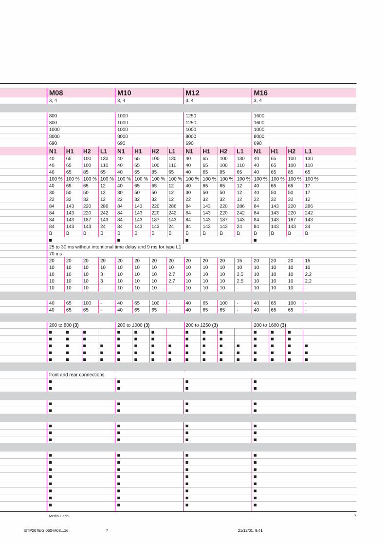
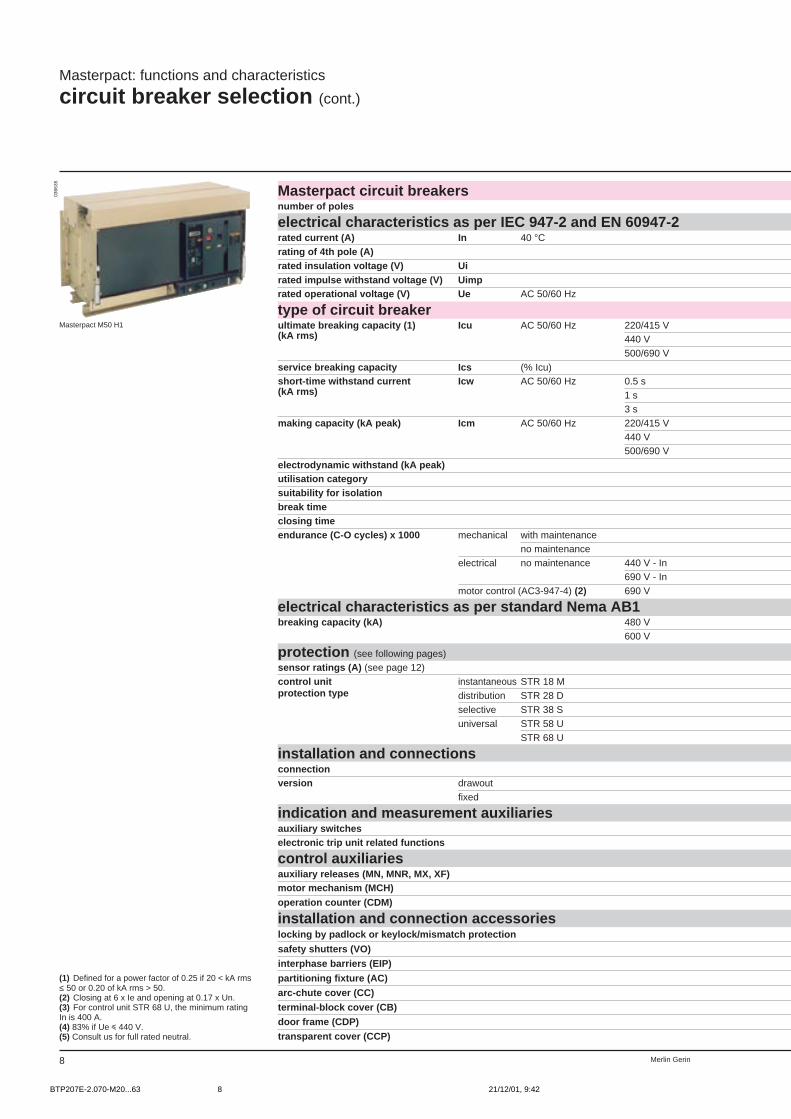
(1) Defined for a power factor of 0.25 if 20 < kA rms≤ 50 or 0.20 of kA rms > 50.(2) Closing at 6 x Ie and opening at 0.17 x Un.(3) For control unit STR 68 U, the minimum ratingIn is 400 A.
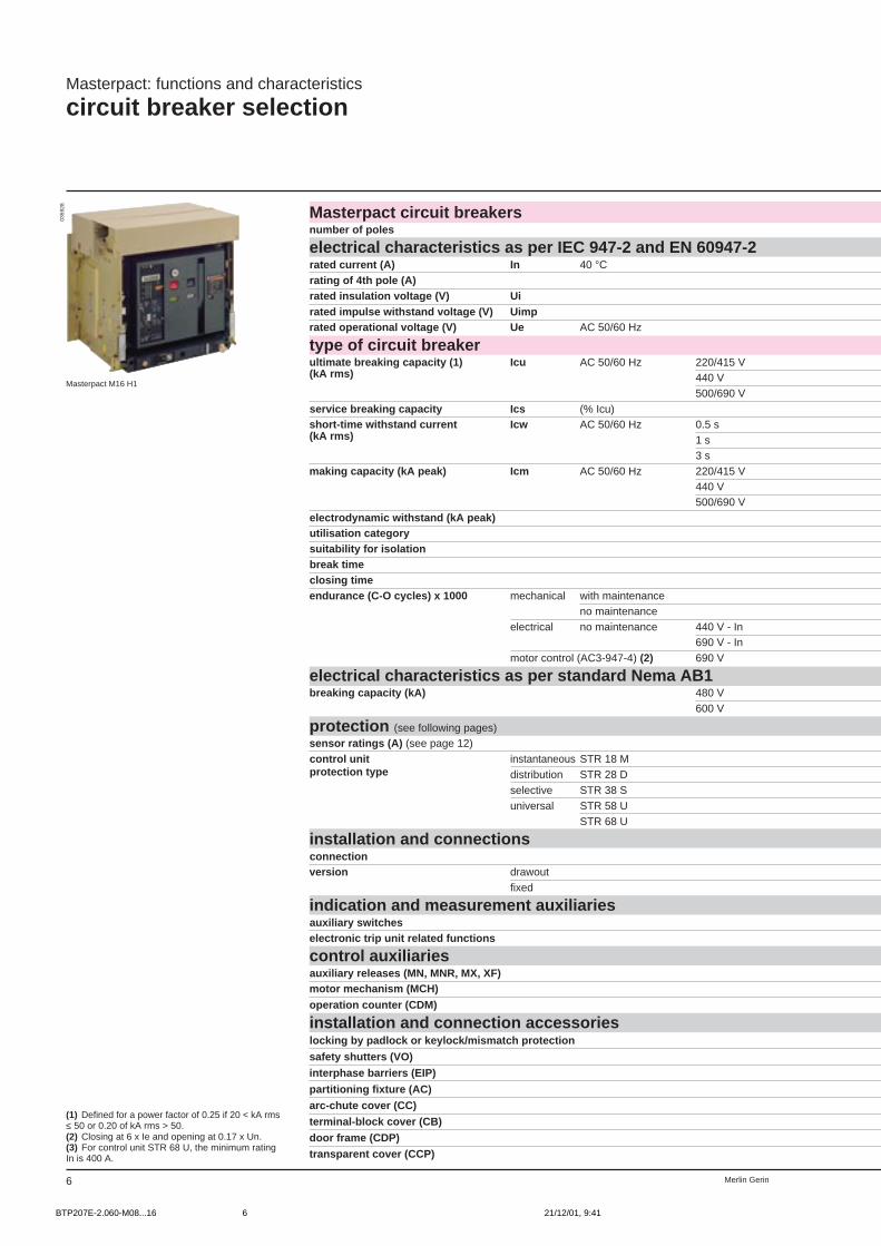
Masterpact circuit breakersnumber of poles
electrical characteristics as per IEC 947-2 and EN 60947-2rated current (A) In 40 °Crating of 4th pole (A)rated insulation voltage (V) Uirated impulse withstand voltage (V) Uimprated operational voltage (V) Ue AC 50/60 Hz
type of circuit breakerultimate breaking capacity (1) Icu AC 50/60 Hz 220/415 V(kA rms) 440 V
500/690 Vservice breaking capacity Ics (% Icu)short-time withstand current Icw AC 50/60 Hz 0.5 s(kA rms) 1 s
3 smaking capacity (kA peak) Icm AC 50/60 Hz 220/415 V
440 V500/690 V
electrodynamic withstand (kA peak)utilisation categorysuitability for isolationbreak timeclosing timeendurance (C-O cycles) x 1000 mechanical with maintenance
no maintenanceelectrical no maintenance 440 V - In
690 V - Inmotor control (AC3-947-4) (2) 690 V
electrical characteristics as per standard Nema AB1breaking capacity (kA) 480 V
600 V
protection (see following pages)sensor ratings (A) (see page 12)control unit instantaneous STR 18 Mprotection type distribution STR 28 D
selective STR 38 Suniversal STR 58 U
STR 68 U
installation and connectionsconnectionversion drawout
fixed
indication and measurement auxiliariesauxiliary switcheselectronic trip unit related functions
control auxiliariesauxiliary releases (MN, MNR, MX, XF)motor mechanism (MCH)operation counter (CDM)
installation and connection accessorieslocking by padlock or keylock/mismatch protection
safety shutters (VO)interphase barriers (EIP)
partitioning fixture (AC)arc-chute cover (CC)terminal-block cover (CB)door frame (CDP)transparent cover (CCP)
0359
28
Masterpact M16 H1
BTP207E-2.060-M08...16 21/12/01, 9:416
7Merlin Gerin
M08 M10 M12 M163, 4 3, 4 3, 4 3, 4
800 1000 1250 1600800 1000 1250 16001000 1000 1000 1000
8000 8000 8000 8000690 690 690 690
N1 H1 H2 L1 N1 H1 H2 L1 N1 H1 H2 L1 N1 H1 H2 L140 65 100 130 40 65 100 130 40 65 100 130 40 65 100 13040 65 100 110 40 65 100 110 40 65 100 110 40 65 100 11040 65 85 65 40 65 85 65 40 65 85 65 40 65 85 65100 % 100 % 100 % 100 % 100 % 100 % 100 % 100 % 100 % 100 % 100 % 100 % 100 % 100 % 100 % 100 %40 65 65 12 40 65 65 12 40 65 65 12 40 65 65 1730 50 50 12 30 50 50 12 30 50 50 12 40 50 50 1722 32 32 12 22 32 32 12 22 32 32 12 22 32 32 1284 143 220 286 84 143 220 286 84 143 220 286 84 143 220 28684 143 220 242 84 143 220 242 84 143 220 242 84 143 220 24284 143 187 143 84 143 187 143 84 143 187 143 84 143 187 14384 143 143 24 84 143 143 24 84 143 143 24 84 143 143 34B B B B B B B B B B B B B B B Bc c c c25 to 30 ms without intentional time delay and 9 ms for type L170 ms20 20 20 20 20 20 20 20 20 20 20 15 20 20 20 1510 10 10 10 10 10 10 10 10 10 10 10 10 10 10 1010 10 10 3 10 10 10 2.7 10 10 10 2.5 10 10 10 2.210 10 10 3 10 10 10 2.7 10 10 10 2.5 10 10 10 2.210 10 10 - 10 10 10 - 10 10 10 - 10 10 10 -
40 65 100 - 40 65 100 - 40 65 100 - 40 65 100 -40 65 65 - 40 65 65 - 40 65 65 - 40 65 65 -
200 to 800 (3) 200 to 1000 (3) 200 to 1250 (3) 200 to 1600 (3)c c c c c c c c c c c cc c c c c c c c c c c cc c c c c c c c c c c c c c c cc c c c c c c c c c c c c c c cc c c c c c c c c c c c c c c c
front and rear connectionsc c c cc c c c
c c c cc c c c
c c c cc c c cc c c c
c c c cc c c cc c c cc c c cc c c cc c c cc c c cc c c c
BTP207E-2.060-M08...16 21/12/01, 9:417
Merlin Gerin8
Masterpact: functions and characteristics
circuit breaker selection (cont.)
Masterpact circuit breakersnumber of poles
electrical characteristics as per IEC 947-2 and EN 60947-2rated current (A) In 40 °Crating of 4th pole (A)rated insulation voltage (V) Uirated impulse withstand voltage (V) Uimprated operational voltage (V) Ue AC 50/60 Hz
type of circuit breakerultimate breaking capacity (1) Icu AC 50/60 Hz 220/415 V(kA rms) 440 V
500/690 Vservice breaking capacity Ics (% Icu)short-time withstand current Icw AC 50/60 Hz 0.5 s(kA rms) 1 s
3 smaking capacity (kA peak) Icm AC 50/60 Hz 220/415 V
440 V500/690 V
electrodynamic withstand (kA peak)utilisation categorysuitability for isolationbreak timeclosing timeendurance (C-O cycles) x 1000 mechanical with maintenance
no maintenanceelectrical no maintenance 440 V - In
690 V - Inmotor control (AC3-947-4) (2) 690 V
electrical characteristics as per standard Nema AB1breaking capacity (kA) 480 V
600 V
protection (see following pages)sensor ratings (A) (see page 12)control unit instantaneous STR 18 Mprotection type distribution STR 28 D
selective STR 38 Suniversal STR 58 U
STR 68 U
installation and connectionsconnectionversion drawout
fixed
indication and measurement auxiliariesauxiliary switcheselectronic trip unit related functions
control auxiliariesauxiliary releases (MN, MNR, MX, XF)motor mechanism (MCH)operation counter (CDM)
installation and connection accessorieslocking by padlock or keylock/mismatch protection
safety shutters (VO)interphase barriers (EIP)
partitioning fixture (AC)arc-chute cover (CC)terminal-block cover (CB)door frame (CDP)transparent cover (CCP)
0366
35
Masterpact M50 H1
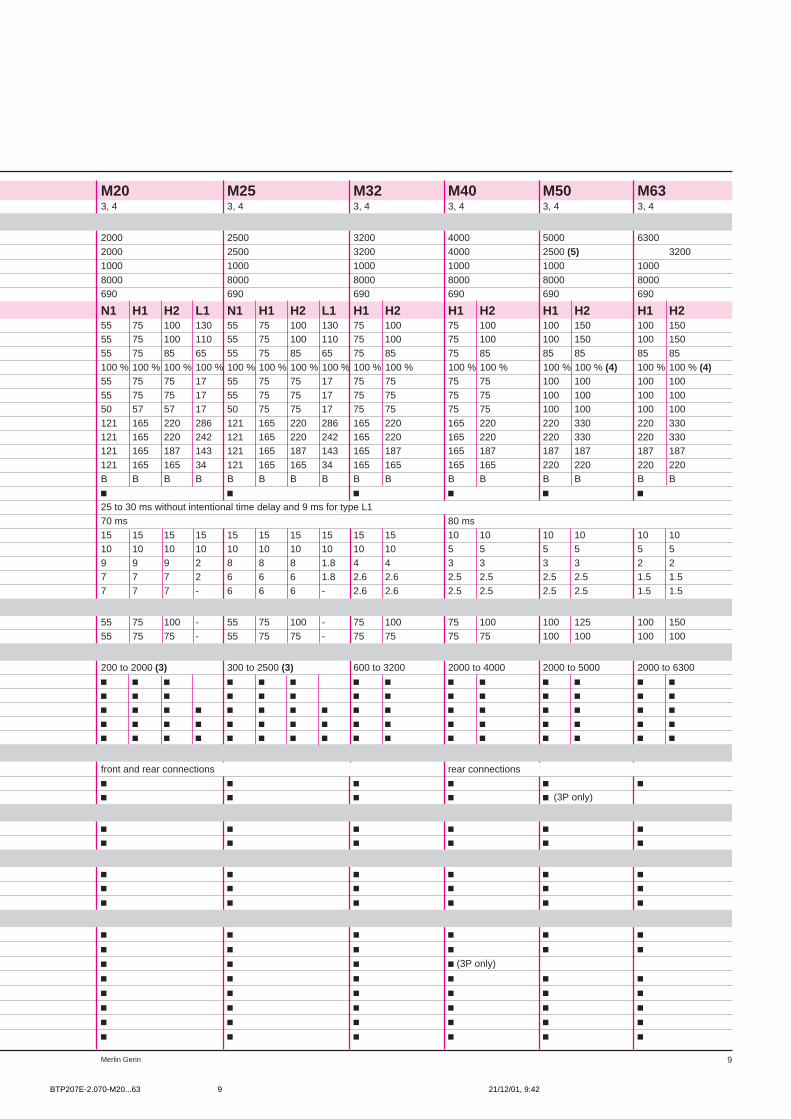
(1) Defined for a power factor of 0.25 if 20 < kA rms≤ 50 or 0.20 of kA rms > 50.(2) Closing at 6 x Ie and opening at 0.17 x Un.(3) For control unit STR 68 U, the minimum ratingIn is 400 A.(4) 83% if Ue i 440 V.(5) Consult us for full rated neutral.
BTP207E-2.070-M20...63 21/12/01, 9:428
9Merlin Gerin
M20 M25 M32 M40 M50 M633, 4 3, 4 3, 4 3, 4 3, 4 3, 4
2000 2500 3200 4000 5000 63002000 2500 3200 4000 2500 (5) 32001000 1000 1000 1000 1000 1000
8000 8000 8000 8000 8000 8000690 690 690 690 690 690
N1 H1 H2 L1 N1 H1 H2 L1 H1 H2 H1 H2 H1 H2 H1 H255 75 100 130 55 75 100 130 75 100 75 100 100 150 100 15055 75 100 110 55 75 100 110 75 100 75 100 100 150 100 15055 75 85 65 55 75 85 65 75 85 75 85 85 85 85 85100 % 100 % 100 % 100 % 100 % 100 % 100 % 100 % 100 % 100 % 100 % 100 % 100 % 100 % (4) 100 % 100 % (4)55 75 75 17 55 75 75 17 75 75 75 75 100 100 100 10055 75 75 17 55 75 75 17 75 75 75 75 100 100 100 10050 57 57 17 50 75 75 17 75 75 75 75 100 100 100 100121 165 220 286 121 165 220 286 165 220 165 220 220 330 220 330121 165 220 242 121 165 220 242 165 220 165 220 220 330 220 330121 165 187 143 121 165 187 143 165 187 165 187 187 187 187 187121 165 165 34 121 165 165 34 165 165 165 165 220 220 220 220B B B B B B B B B B B B B B B Bc c c c c c25 to 30 ms without intentional time delay and 9 ms for type L170 ms 80 ms15 15 15 15 15 15 15 15 15 15 10 10 10 10 10 1010 10 10 10 10 10 10 10 10 10 5 5 5 5 5 59 9 9 2 8 8 8 1.8 4 4 3 3 3 3 2 27 7 7 2 6 6 6 1.8 2.6 2.6 2.5 2.5 2.5 2.5 1.5 1.57 7 7 - 6 6 6 - 2.6 2.6 2.5 2.5 2.5 2.5 1.5 1.5
55 75 100 - 55 75 100 - 75 100 75 100 100 125 100 15055 75 75 - 55 75 75 - 75 75 75 75 100 100 100 100
200 to 2000 (3) 300 to 2500 (3) 600 to 3200 2000 to 4000 2000 to 5000 2000 to 6300c c c c c c c c c c c c c cc c c c c c c c c c c c c cc c c c c c c c c c c c c c c cc c c c c c c c c c c c c c c cc c c c c c c c c c c c c c c c
front and rear connections rear connectionsc c c c c cc c c c c (3P only)
c c c c c cc c c c c c
c c c c c cc c c c c cc c c c c c
c c c c c cc c c c c cc c c c (3P only)
c c c c c cc c c c c cc c c c c cc c c c c cc c c c c c
BTP207E-2.070-M20...63 21/12/01, 9:429

Merlin Gerin10
Masterpact: functions and characteristics
circuit breaker selection (cont.)
Masterpact 1000 V AC
Masterpact 1000 V AC circuit breakersnumber of poles
electrical characteristics as per IEC 947-2 and EN 60947-2rated current (A) In 40 °Crating of 4th pole (A)rated insulation voltage (V) Uirated impulse withstand voltage (V) Uimprated operational voltage (V) Ue AC 50/60 Hz
type of circuit breakerultimate breaking capacity (1) Icu AC 50/60 Hz 220/415 V(kA rms) 440 V
500/690 V1000 V
service breaking capacity Ics (% Icu)short-time withstand current Icw AC 50/60 Hz 0.5 s(kA rms) 1 s
3 smaking capacity (kA peak) Icm AC 50/60 Hz 220/415 V
440 V500/690 V1000 V
electrodynamic withstand (kA peak)utilisation categorysuitability for isolationbreak timeclosing timeendurance (C-O cycles) x 1000 mechanical with maintenance
no maintenanceelectrical no maintenance 440 V - In
690 V - Inmotor control (AC3-947-4) (2) 690 V
protection (see following pages)sensor ratings (A) (see page 12)control unit instantaneous STR 18 Mprotection type distribution STR 28 D
selective STR 38 Suniversal STR 58 U
STR 68 U
installation and connectionsconnectionversion drawout
fixed
indication and measurement auxiliariesauxiliary switcheselectronic trip unit related functions
control auxiliariesauxiliary releases (MN, MNR, MX, XF)motor mechanism (MCH)operation counter (CDM)
installation and connection accessorieslocking by padlock or keylock/mismatch protection
safety shutters (VO)interphase barriers (EIP)partitioning fixture (AC)arc-chute cover (CC) (as standard on the 1000 V version)
terminal-block cover (CB)door frame (CDP)transparent cover (CCP)
(1) Defined for a power factor of 0.25 if 20 < kA rms≤ 50 or 0.20 of kA rms > 50.(2) Closing at 6 x Ie and opening at 0.17 x Un.(3) For control unit STR 68 U, the minimum ratingIn is 400 A.
Masterpact M20 H1 1000 V
0523
80
BTP207E-2.080-M08...32 21/12/01, 9:4210

11Merlin Gerin
M08 M10 M12 M16 M20 M25 M323, 4 3, 4 3, 4 3, 4 3, 4 3, 4 3, 4
800 1000 1250 1600 2000 2500 3200800 1000 1250 1600 2000 2500 32001000 1000 1000 1000 1000 1000 1000
8000 8000 8000 8000 8000 8000 80001000 1000 1000 1000 1000 1000 1000
H1 H1 H1 H1 H1 H1 H165 65 65 65 75 75 7565 65 65 65 75 75 7565 65 65 65 75 75 7545 45 45 45 45 45 45100 % 100 % 100 % 100 % 100 % 100 % 100 %45 45 45 45 45 45 4545 45 45 45 45 45 4532 32 32 32 45 45 4595 95 95 95 95 95 95143 143 143 143 165 165 165143 143 143 143 165 165 165143 143 143 143 165 165 165143 143 143 143 165 165 165B B B B B B Bc c c c c c c25 to 30 ms without intentional time delay and 9 ms for type L170 ms20 20 20 20 15 15 1510 10 10 10 10 10 1010 10 10 10 9 8 410 10 10 10 7 6 2.610 10 10 10 7 6 2.6
200 to 800 (3) 200 to 1000 (3) 200 to 1250 (3) 200 to 1600 (3) 200 to 2000 (3) 300 to 2500 (3) 600 to 3200c c c c c c cc c c c c c cc c c c c c cc c c c c c cc c c c c c c
rear connections only / supply by upstream terminals mandatoryc c c c c c c
c c c c c c cc c c c c c c
c c c c c c cc c c c c c cc c c c c c c
c c c c c c cc c c c c c cc c c c c c cc c c c c c cc c c c c c cc c c c c c cc c c c c c cc c c c c c c
BTP207E-2.080-M08...32 21/12/01, 9:4211
Merlin Gerin12
Masterpact: functions and characteristics
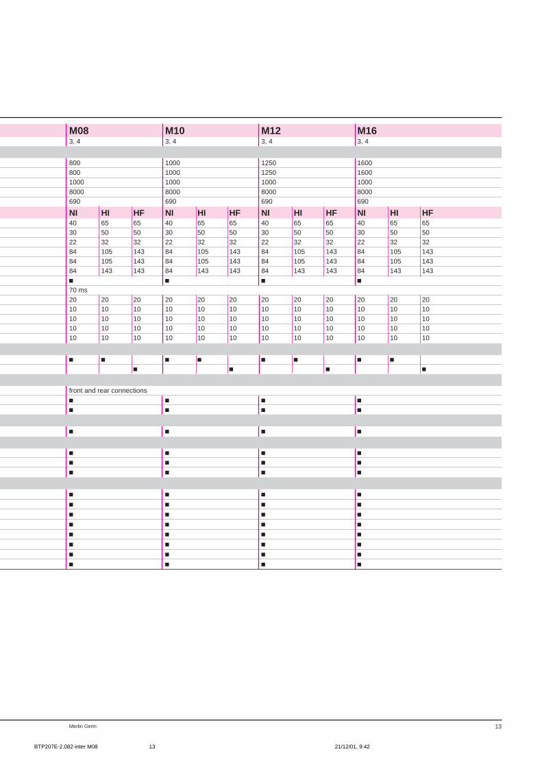
switch-disconnectors
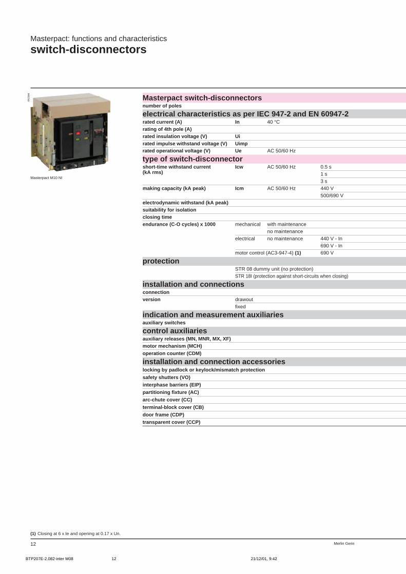
Masterpact switch-disconnectorsnumber of poles
electrical characteristics as per IEC 947-2 and EN 60947-2rated current (A) In 40 °Crating of 4th pole (A)rated insulation voltage (V) Uirated impulse withstand voltage (V) Uimprated operational voltage (V) Ue AC 50/60 Hz
type of switch-disconnectorshort-time withstand current Icw AC 50/60 Hz 0.5 s(kA rms) 1 s
3 smaking capacity (kA peak) Icm AC 50/60 Hz 440 V
500/690 Velectrodynamic withstand (kA peak)suitability for isolationclosing timeendurance (C-O cycles) x 1000 mechanical with maintenance
no maintenanceelectrical no maintenance 440 V - In
690 V - Inmotor control (AC3-947-4) (1) 690 V
protectionSTR 08 dummy unit (no protection)STR 18I (protection against short-circuits when closing)
installation and connectionsconnectionversion drawout
fixed
indication and measurement auxiliariesauxiliary switches
control auxiliariesauxiliary releases (MN, MNR, MX, XF)motor mechanism (MCH)operation counter (CDM)
installation and connection accessorieslocking by padlock or keylock/mismatch protection
safety shutters (VO)interphase barriers (EIP)partitioning fixture (AC)arc-chute cover (CC)
terminal-block cover (CB)door frame (CDP)transparent cover (CCP)
(1) Closing at 6 x Ie and opening at 0.17 x Un.
Masterpact M10 NI
0523
84
BTP207E-2.082-inter M08 21/12/01, 9:4212
13Merlin Gerin
M08 M10 M12 M163, 4 3, 4 3, 4 3, 4
800 1000 1250 1600800 1000 1250 16001000 1000 1000 1000
8000 8000 8000 8000690 690 690 690
NI HI HF NI HI HF NI HI HF NI HI HF40 65 65 40 65 65 40 65 65 40 65 6530 50 50 30 50 50 30 50 50 30 50 5022 32 32 22 32 32 22 32 32 22 32 3284 105 143 84 105 143 84 105 143 84 105 14384 105 143 84 105 143 84 105 143 84 105 14384 143 143 84 143 143 84 143 143 84 143 143c c c c70 ms20 20 20 20 20 20 20 20 20 20 20 2010 10 10 10 10 10 10 10 10 10 10 1010 10 10 10 10 10 10 10 10 10 10 1010 10 10 10 10 10 10 10 10 10 10 1010 10 10 10 10 10 10 10 10 10 10 10
c c c c c c c cc c c c
front and rear connectionsc c c cc c c c
c c c c
c c c cc c c cc c c c
c c c cc c c cc c c cc c c cc c c cc c c cc c c cc c c c
BTP207E-2.082-inter M08 21/12/01, 9:4213
Merlin Gerin12
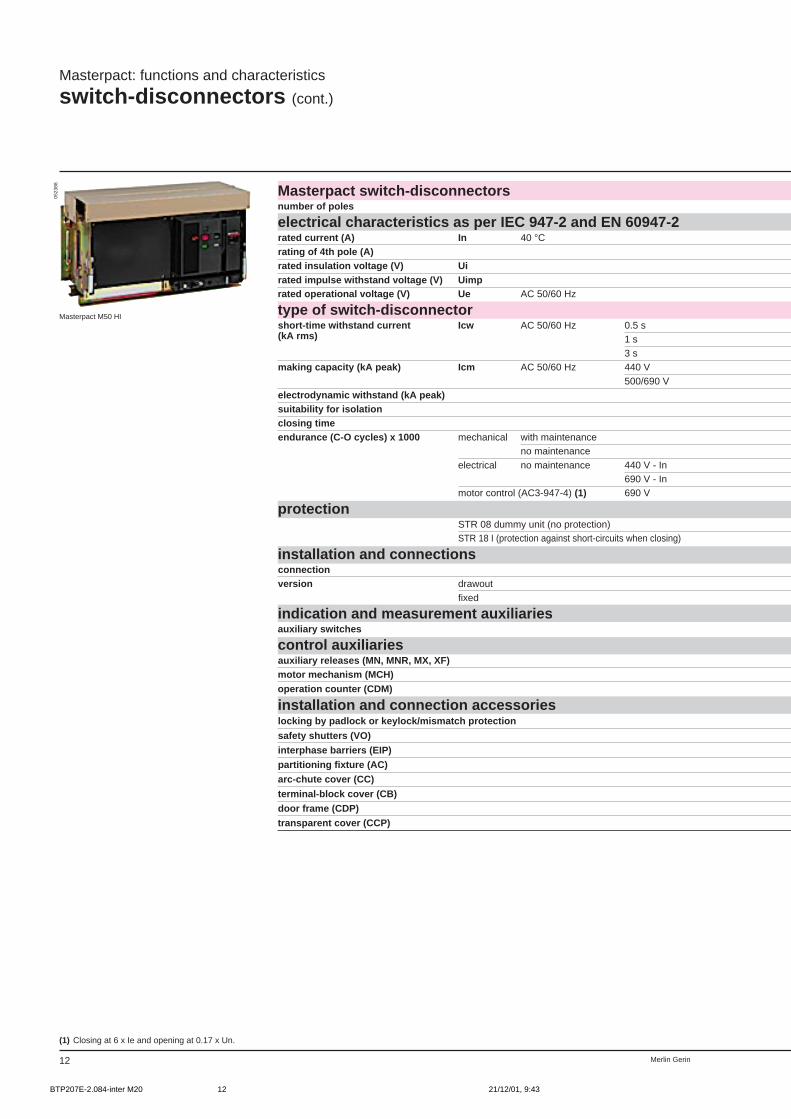
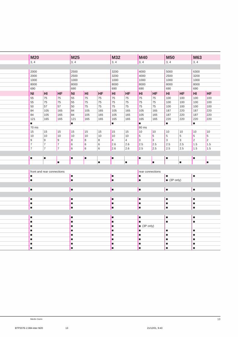
Masterpact: functions and characteristics
switch-disconnectors (cont.)
Masterpact switch-disconnectorsnumber of poles
electrical characteristics as per IEC 947-2 and EN 60947-2rated current (A) In 40 °Crating of 4th pole (A)rated insulation voltage (V) Uirated impulse withstand voltage (V) Uimprated operational voltage (V) Ue AC 50/60 Hz
type of switch-disconnectorshort-time withstand current Icw AC 50/60 Hz 0.5 s(kA rms) 1 s
3 smaking capacity (kA peak) Icm AC 50/60 Hz 440 V
500/690 Velectrodynamic withstand (kA peak)suitability for isolationclosing timeendurance (C-O cycles) x 1000 mechanical with maintenance
no maintenanceelectrical no maintenance 440 V - In
690 V - Inmotor control (AC3-947-4) (1) 690 V
protectionSTR 08 dummy unit (no protection)STR 18 I (protection against short-circuits when closing)
installation and connectionsconnectionversion drawout
fixed
indication and measurement auxiliariesauxiliary switches
control auxiliariesauxiliary releases (MN, MNR, MX, XF)motor mechanism (MCH)operation counter (CDM)
installation and connection accessorieslocking by padlock or keylock/mismatch protection
safety shutters (VO)interphase barriers (EIP)partitioning fixture (AC)arc-chute cover (CC)
terminal-block cover (CB)door frame (CDP)transparent cover (CCP)
(1) Closing at 6 x Ie and opening at 0.17 x Un.
Masterpact M50 HI
0523
88
BTP207E-2.084-inter M20 21/12/01, 9:4312
13Merlin Gerin
M20 M25 M32 M40 M50 M633, 4 3, 4 3, 4 3, 4 3, 4 3, 4
2000 2500 3200 4000 5000 63002000 2500 3200 4000 2500 32001000 1000 1000 1000 1000 1000
8000 8000 8000 8000 8000 8000690 690 690 690 690 690
NI HI HF NI HI HF HI HF HI HF HI HF HI HF55 75 75 55 75 75 75 75 75 75 100 100 100 10055 75 75 55 75 75 75 75 75 75 100 100 100 10050 57 57 50 75 75 75 75 75 75 100 100 100 10084 105 165 84 105 165 105 165 105 165 187 220 187 22084 105 165 84 105 165 105 165 105 165 187 220 187 220121 165 165 121 165 165 165 165 165 165 220 220 220 220c c c c c c70 ms 80 ms15 15 15 15 15 15 15 15 10 10 10 10 10 1010 10 10 10 10 10 10 10 5 5 5 5 5 59 9 9 8 8 8 4 4 3 3 3 3 2 27 7 7 6 6 6 2.6 2.6 2.5 2.5 2.5 2.5 1.5 1.57 7 7 6 6 6 2.6 2.6 2.5 2.5 2.5 2.5 1.5 1.5
c c c c c c c cc c c c c c
front and rear connections rear connectionsc c c c c cc c c c c (3P only)
c c c c c c
c c c c c cc c c c c cc c c c c c
c c c c c cc c c c c cc c c c (3P only)
c c c c c cc c c c c cc c c c c cc c c c c cc c c c c c
BTP207E-2.084-inter M20 21/12/01, 9:4313
Merlin Gerin12
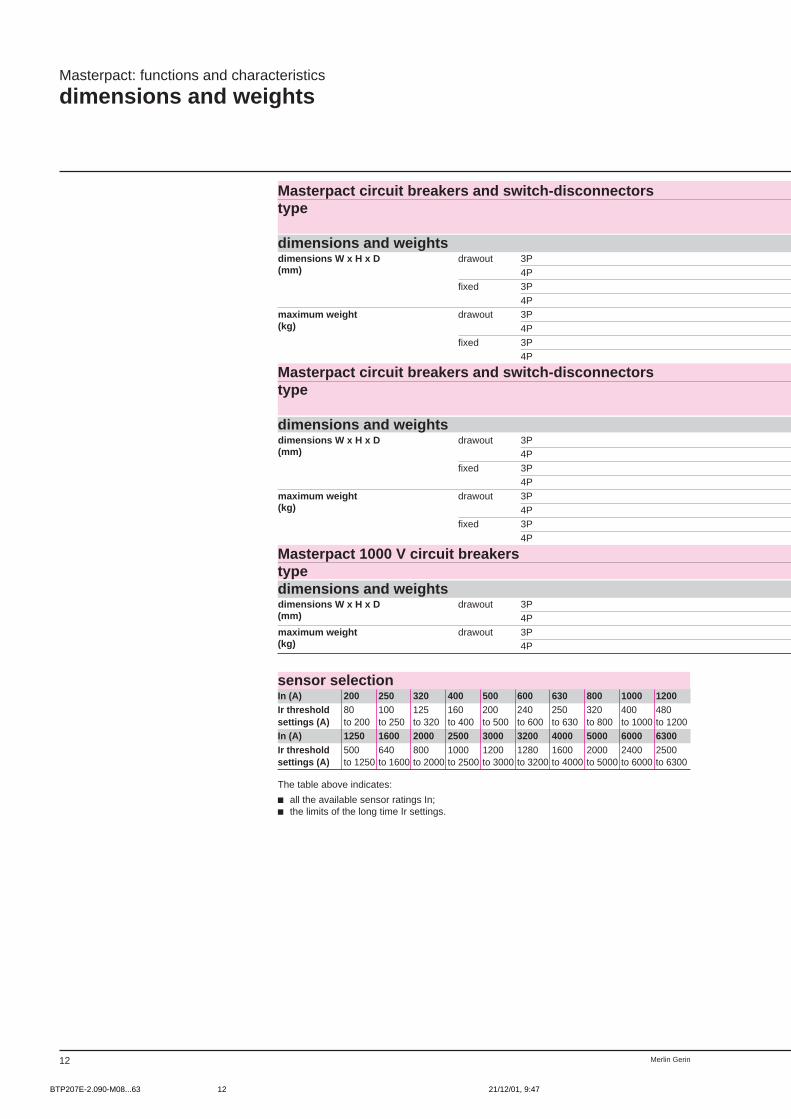
Masterpact: functions and characteristics
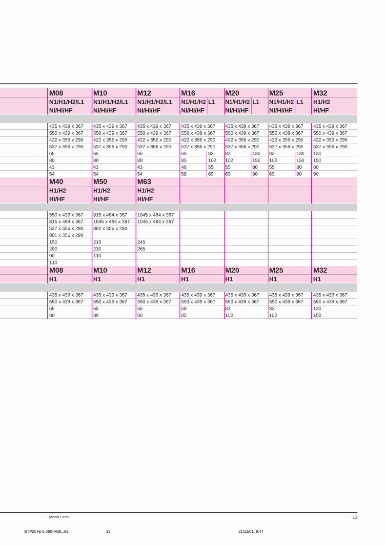
dimensions and weights
Masterpact circuit breakers and switch-disconnectorstype
dimensions and weightsdimensions W x H x D drawout 3P(mm) 4P
fixed 3P4P
maximum weight drawout 3P(kg) 4P
fixed 3P4P
Masterpact circuit breakers and switch-disconnectorstype
dimensions and weightsdimensions W x H x D drawout 3P(mm) 4P
fixed 3P4P
maximum weight drawout 3P(kg) 4P
fixed 3P4P
Masterpact 1000 V circuit breakerstypedimensions and weightsdimensions W x H x D drawout 3P(mm) 4Pmaximum weight drawout 3P(kg) 4P
sensor selectionIn (A) 200 250 320 400 500 600 630 800 1000 1200Ir threshold 80 100 125 160 200 240 250 320 400 480settings (A) to 200 to 250 to 320 to 400 to 500 to 600 to 630 to 800 to 1000 to 1200In (A) 1250 1600 2000 2500 3000 3200 4000 5000 6000 6300Ir threshold 500 640 800 1000 1200 1280 1600 2000 2400 2500settings (A) to 1250 to 1600 to 2000 to 2500 to 3000 to 3200 to 4000 to 5000 to 6000 to 6300
The table above indicates:
c all the available sensor ratings In;c the limits of the long time Ir settings.
BTP207E-2.090-M08...63 21/12/01, 9:4712
13Merlin Gerin
M08 M10 M12 M16 M20 M25 M32N1/H1/H2/L1 N1/H1/H2/L1 N1/H1/H2/L1 N1/H1/H2 L1 N1/H1/H2 L1 N1/H1/H2 L1 H1/H2NI/HI/HF NI/HI/HF NI/HI/HF NI/HI/HF NI/HI/HF NI/HI/HF HI/HF
435 x 439 x 367 435 x 439 x 367 435 x 439 x 367 435 x 439 x 367 435 x 439 x 367 435 x 439 x 367 435 x 439 x 367550 x 439 x 367 550 x 439 x 367 550 x 439 x 367 550 x 439 x 367 550 x 439 x 367 550 x 439 x 367 550 x 439 x 367422 x 356 x 290 422 x 356 x 290 422 x 356 x 290 422 x 356 x 290 422 x 356 x 290 422 x 356 x 290 422 x 356 x 290537 x 356 x 290 537 x 356 x 290 537 x 356 x 290 537 x 356 x 290 537 x 356 x 290 537 x 356 x 290 537 x 356 x 29065 65 65 69 82 82 130 82 130 13080 80 80 85 102 102 150 102 150 15043 43 43 46 55 55 80 55 80 8054 54 54 58 69 69 90 69 90 90
M40 M50 M63H1/H2 H1/H2 H1/H2HI/HF HI/HF HI/HF
550 x 439 x 367 815 x 484 x 367 1045 x 484 x 367815 x 484 x 367 1045 x 484 x 367 1045 x 484 x 367537 x 356 x 290 802 x 356 x 290801 x 356 x 290150 215 245200 230 26590 110110
M08 M10 M12 M16 M20 M25 M32H1 H1 H1 H1 H1 H1 H1
435 x 439 x 367 435 x 439 x 367 435 x 439 x 367 435 x 439 x 367 435 x 439 x 367 435 x 439 x 367 435 x 439 x 367550 x 439 x 367 550 x 439 x 367 550 x 439 x 367 550 x 439 x 367 550 x 439 x 367 550 x 439 x 367 550 x 439 x 36765 65 65 69 82 82 13080 80 80 85 102 102 150
BTP207E-2.090-M08...63 21/12/01, 9:4713
Merlin Gerin14
16080 1250 2000 2500 4000 6300500032001600400
STR 18 M
STR 28 D
STR 38 S
STR 58 U
STR 68 U
Masterpact: functions and characteristics
control unit selection
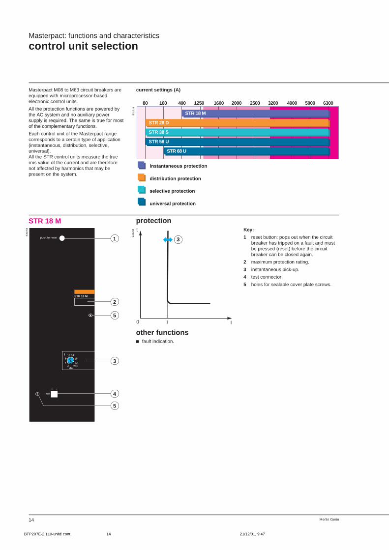
Masterpact M08 to M63 circuit breakers areequipped with microprocessor-basedelectronic control units.
All the protection functions are powered bythe AC system and no auxiliary powersupply is required. The same is true for mostof the complementary functions.
Each control unit of the Masterpact rangecorresponds to a certain type of application(instantaneous, distribution, selective,universal).All the STR control units measure the truerms value of the current and are thereforenot affected by harmonics that may bepresent on the system.
current settings (A)
protectionSTR 18 M
3
I I
t
0
push to reset
STR 18 M
I
xIn
test
+ –
1
812 14
19
22max2
4
2
5
3
4
5
Key:
1 reset button: pops out when the circuitbreaker has tripped on a fault and mustbe pressed (reset) before the circuitbreaker can be closed again.
2 maximum protection rating.
3 instantaneous pick-up.
4 test connector.
5 holes for sealable cover plate screws.
instantaneous protection
distribution protection
selective protection
universal protection
E31
218
E31
219
E30
703
other functionsc fault indication.
BTP207E-2.110-unité cont. 21/12/01, 9:4714
15Merlin Gerin
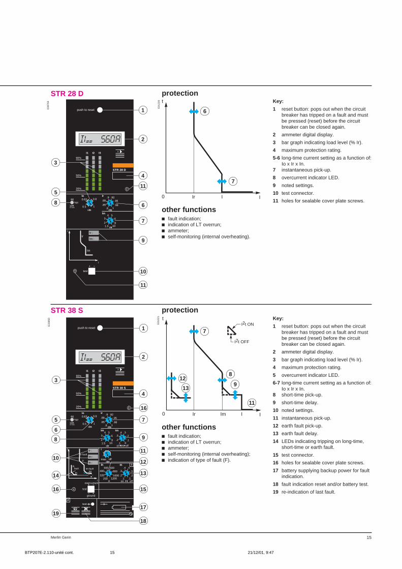
protectionSTR 28 DKey:
1 reset button: pops out when the circuitbreaker has tripped on a fault and mustbe pressed (reset) before the circuitbreaker can be closed again.
2 ammeter digital display.
3 bar graph indicating load level (% Ir).
4 maximum protection rating.
5-6 long-time current setting as a function of:Io x Ir x In.
7 instantaneous pick-up.
8 overcurrent indicator LED.
9 noted settings.
10 test connector.
11 holes for sealable cover plate screws.
push to reset
II1 I2 I3
90%
50%
20%
STR 28 D
Io
xIn
90
105%Ir
xIoIm
xIr
Ir
Im
t
i
test
+ –
Ir :
Im :
Ir
1
.88.9 .92
.95
.981.8
.850.5
0.63 0.8
1
34 5
6
8101.5
2
2
3
4
115
6
7
9
8
10
11
protectionSTR 38 SKey:
1 reset button: pops out when the circuitbreaker has tripped on a fault and mustbe pressed (reset) before the circuitbreaker can be closed again.
2 ammeter digital display.
3 bar graph indicating load level (% Ir).
4 maximum protection rating.
5 overcurrent indicator LED.
6-7 long-time current setting as a function of:Io x Ir x In.
8 short-time pick-up.
9 short-time delay.
10 noted settings.
11 instantaneous pick-up.
12 earth fault pick-up.
13 earth fault delay.
14 LEDs indicating tripping on long-time,short-time or earth fault.
15 test connector.
16 holes for sealable cover plate screws.
17 battery supplying backup power for faultindication.
18 fault indication reset and/or battery test.
19 re-indication of last fault.
push to reset
II1 I2 I3
90%
50%
20%
STR 38 S
xIn xIoIm tm
xIr on I2t off
Ir fault
tr
Im faulttm
I
faultIh
th
t
i
test
+ –
– +
T
Ftest
Ih th
A on I2t off
I
xIn
Ir :
Im :
th :
overcurrent
ground
1
2
3
4
1690
105%Ir
Io
0.5
0.63 0.8
1
Ir
.88.9 .92
.95
.981.8
.85
34 5
6
8101.5
2
.3.4 .3
.2
.10.1
.2
max. off
400500 600
800
10001200250
320
.3.4 .4
.3
.2.1.1
.2
5
6
7
8 9
12
11
1314
16 15
1918
17
10
7
6
I IIr
t
0
other functionsc fault indication;c indication of LT overrun;c ammeter;c self-monitoring (internal overheating).
11
Ir Im
8
I I
t
0
7
912
13
I2t ON
I2t OFF
other functionsc fault indication;c indication of LT overrun;c ammeter;c self-monitoring (internal overheating);c indication of type of fault (F).
E30
704
E31
220
E31
221
E33
950
BTP207E-2.110-unité cont. 21/12/01, 9:4715
Merlin Gerin16
Masterpact: functions and characteristics
control unit selection (cont.)
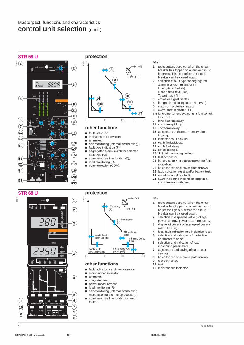
protectionSTR 58 U
push to reset
II1 I2 I3
90%
50%
20%
STR 58 U
τ tr
Ir fault
tr
Im faulttm
I
faultIh
th
t
i
test
+ –
– +
T
R
Ftest
Ir :
Im :
th :
Max.
norm
overcurrent
ground
2
3
4
5
21
6
7
8
21
16
V
reset V II+T L+I
L+I+T
ToffL
L+T
xIn
Io
0.5
0.63 0.8
1
90
105%Ir
.88.9 .92
.95
.981.8
.85
Ir
xIo
60120 240
48015
30
tr
at 1.5IrIm tm
xIr on I2t off
34 5
6
8101.5
2
.3.4 .3
.2
.10.1
.2
I
xInoff
2219
141284
2
Ih 1200A Max th
A on I2t off
400500 600
800
10001200250
320
.3.4 .4
.3
.2.1.1
.2
Ic1 Ic2
xIr
.86.9 .93
.95
.9818
.85
.7.8 .85
.9
.951.5
.6
xIr
1
12
9
10
11
13
15
14
17
19
24 18
2023
22
protectionSTR 68 U
STR 68 U
reset
1 2 3 max
A
Ir Im I
s
Ih
tmth
fault
adjustments
24 V DC
test
KA
S
1
tr
A
trip no trip MEM
test
2%
load monitoringmaintenance
N 1 2 3
Hz
Cos ϕ
kW
MWh
+–
685812
V
10
88
9
7
611
5
4
3
2
2
1Key:
1 reset button: pops out when the circuitbreaker has tripped on a fault and mustbe pressed (reset) before the circuitbreaker can be closed again.
2 selection of displayed value (voltage,power, energy, power factor, frequency).
3 display of current or interrupted current(when flashing).
4 local fault indication and indication reset.5 selection and indication of protection
parameter to be set.6 selection and indication of load
monitoring parameters.7 adjustment and saving of parameter
settings.8 holes for sealable cover plate screws.9 test connector.10 test.11 maintenance indicator.
Ir Im I I
t
0
I2t ON
I2t OFFLT setting(Ir)
ST pick-up(Im)
ST time delay(tm)
instantaneouspick-up (I)
earth fault time delay (th)
earth faultpick-up (Ih)
LT time delay(tr)
other functionsc fault indications and memorisation;c maintenance indicator;c ammeter;c integrated test;c power measurement;c load monitoring (R);c self-monitoring (internal overheating,
malfunction of the microprocessor);c zone selective interlocking for earth
faults.
other functionsc fault indication;c indication of LT overrun;c ammeter;c self-monitoring (internal overheating);c fault type indication (F);c segregated alarm switch for selected
fault type (V);c zone selective interlocking (Z);c load monitoring (R);c communication (COM).
9
13
Ir Im
10
I I
t
0
8
1114
15
I2t ON
I2t OFF
E30
705
E31
222
E31
223
E33
949
Key:
1 reset button: pops out when the circuitbreaker has tripped on a fault and mustbe pressed (reset) before the circuitbreaker can be closed again.
2 selection of fault type for segregatedalarm: Ir and/or Im and/or IhL: long-time fault (Ir)I: short-time fault (Im/l)T: earth fault (Ih)
3 ammeter digital display.4 bar graph indicating load level (% Ir).5 maximum protection rating.6 overcurrent indicator LED.7-8 long-time current setting as a function of:
Io x Ir x In.9 long-time trip delay10 short-time pick-up.11 short-time delay.12 adjustment of thermal memory after
tripping.13 instantaneous pick-up.14 earth fault pick-up.15 earth fault delay.16 noted settings.17-18 load monitoring settings.19 test connector.20 battery supplying backup power for fault
indication.21 holes for sealable cover plate screws.22 fault indication reset and/or battery test.23 re-indication of last fault.24 LEDs indicating tripping on long-time,
short-time or earth fault.
BTP207E-2.120-unité cont. 21/12/01, 9:5016
17Merlin Gerin
I
t
0
Ih
Th
I2t ON
I2t OFF
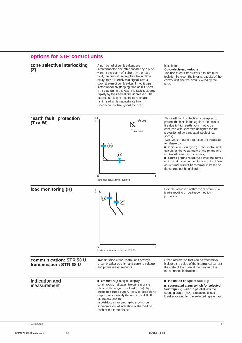
options for STR control units
zone selective interlocking(Z)
"earth fault" protection(T or W)
This earth fault protection is designed toprotect the installation against the risks offire due to high earth faults (not to beconfused with schemes designed for theprotection of persons against electricalshock).Two types of earth protection are availablefor Masterpact:c residual current type (T): the control unitcalculates the vector sum of the phase andneutral (if distributed) currents;c source ground return type (W): the controlunit acts directly on the signal received froman external current transformer installed onthe source earthing circuit.
earth fault curves for the STR 58
load monitoring (R) Remote indication of threshold overrun forload-shedding or load-reconnectionpurposes.
I
t
0
Ic2Ic1
load monitoring curves for the STR 58
communication: STR 58 Utransmission: STR 68 U
Transmission of the control unit settings,circuit breaker position and current, voltageand power measurements.
indication andmeasurement
c ammeter (I): a digital displaycontinuously indicates the current of thephase with the greatest load (Imax). Bypressing a scroll button, it is also possible todisplay successively the readings of I1, I2,I3, Ineutral and Ih.In addition, three bargraphs provide animmediate visual indication of the load oneach of the three phases.
E26
037
E31
225
A number of circuit breakers areinterconnected one after another by a pilot-wire. In the event of a short-time or earthfault, the control unit applies the set timedelay only if it receives a signal from adownstream circuit breaker. If not, it tripsinstantaneously (tripping time as 0.1 short-time setting). In this way, the fault is clearedrapidly by the nearest circuit breaker. Thethermal stresses in the installation areminimised while maintaining timediscrimination throughout the entire
installation.Opto-electronic outputsThe use of opto-transistors ensures totalisolation between the internal circuits of thecontrol unit and the circuits wired by theuser.
Other information that can be transmittedincludes the value of the interrupted current,the state of the thermal memory and themaintenance indications
c indication of type of fault (F);
c segregated alarm switch for selectedfault type (V) , wired in parallel with theopening button (MX), it disables circuitbreaker closing for the selected type of fault.
BTP207E-2.120-unité cont. 21/12/01, 9:5017

Merlin Gerin18
Masterpact: functions and characteristics
control unit selection (cont.)
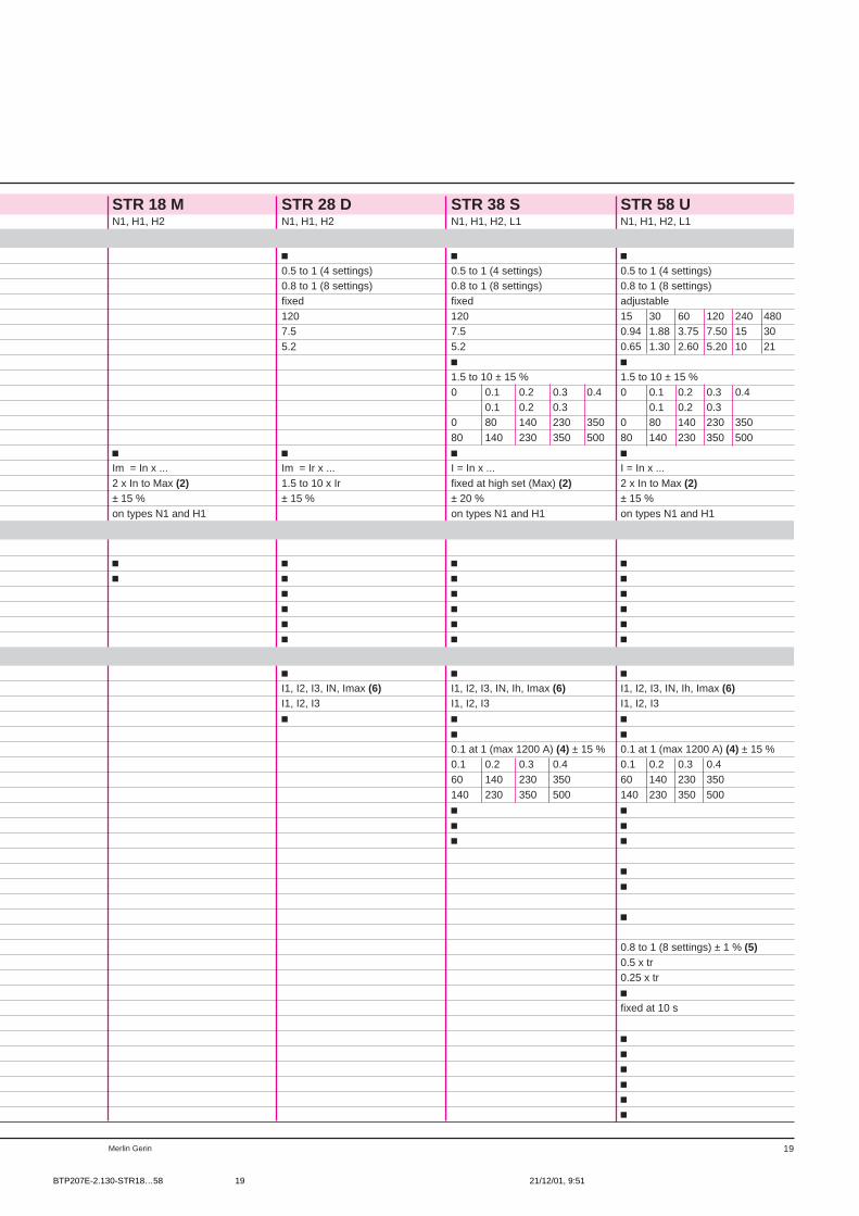
STR 18 M to STR 58 U
control unittype of circuit breaker
basic protectionlong time protection LT
current setting (Ir) as a function of Io and Ir Io = In x ...settings tripping between 1.05 and 1.20 x Ir Ir = Io x ...time delay (tr)accuracy: + 0 - 20 % tr at 1.5 Ir (s)
tr at 6 Ir (s)tr at 7.2 Ir (s)
short-time protection STpick-up (Im) adjustable by Im setting Im = Ir x ...time delay (tm) tm setting with I2t OFF
tm setting with I2t ONmax. overcurrent time before tripping (ms)max. break time (ms)
instantaneous protection Ipick-up settingsetting rangeaccuracyOFF switch on front face
basic functionsfault indication
for tripping on a fault indicator button on front facefault trip alarm contact (SDE)
for LT setting overrun LED (lights up at 0.9 Ir and flashes at 1.05 Ir)LT overrun alarm contact (optional)self-powered
self-monitoring internal overheating
optional functionsammeter (I) display between 0.2 and 1.20 In
current readings with an accuracy of ± 1.5 % (1) (3)bargraph indication of current levels with a resolution of 10 %self-powered
earth fault protection: residual current (T) or source ground return (W) type on requestpick-up adjustable by Ih setting Ih = In x ...time delay (th) th setting with I2t ON and I2t OFF
max. overcurrent time before tripping (ms)max. break time (ms)
indication of type of fault (F) (LT - CT/Inst. - Earth) by LEDs on front facepower supply with battery module
with external power supply by AD module
segregated alarm switch for selected fault type (V) (LT - CT/Inst. - Earth)output via relay contactpower supply by AD module
zone selective interlocking (Z)by opto-electronic contact on ST and earth (T/W) fault
load monitoring (R)adjustment of load limit thresholds by Ic1 and Ic2 settings Ic1 = Ir x ... / Ic2 = Ir x ...time delay tr1 at 1.5 Ic1time delay tr2 at 1.5 Ic2output via opto-electronic contact 0.1 A / 240 Vtime delay for load reconnection
communication (COM)2 outputs for data transmission to Dialpact moduletransmitted values all control unit settings
alarms: Ir warning, fault type, self-monitoringload monitoring thresholdscurrent values I1, I2, I3, IN
power supply by AD module
STR 58 U
0484
49
(1) Plus the uncertainty of the built-in transformers:± 3 %.
(2) Max = In x ... N1/H1 H2 L1630 A 22 28 14800 - 1000 A 22 28 101200 - 1600 A 22 24 82000 A 17 20 62500 A 12 14 63000 - 3200 A 10 12 –4000 - 6300 A 8 10 –
(3) Continuous display for the phase with thegreatest load.
(4) 0.2 x In to 1200 A without external powersupply or 0.1 x In with external power supply.
(5) Accuracy with respect to the long time LTprotection.
(6) Resettable maximum ammeter.
BTP207E-2.130-STR18…58 21/12/01, 9:5118
19Merlin Gerin
STR 18 M STR 28 D STR 38 S STR 58 UN1, H1, H2 N1, H1, H2 N1, H1, H2, L1 N1, H1, H2, L1
c c c0.5 to 1 (4 settings) 0.5 to 1 (4 settings) 0.5 to 1 (4 settings)0.8 to 1 (8 settings) 0.8 to 1 (8 settings) 0.8 to 1 (8 settings)fixed fixed adjustable120 120 15 30 60 120 240 4807.5 7.5 0.94 1.88 3.75 7.50 15 305.2 5.2 0.65 1.30 2.60 5.20 10 21
c c1.5 to 10 ± 15 % 1.5 to 10 ± 15 %0 0.1 0.2 0.3 0.4 0 0.1 0.2 0.3 0.4
0.1 0.2 0.3 0.1 0.2 0.30 80 140 230 350 0 80 140 230 35080 140 230 350 500 80 140 230 350 500
c c c cIm = In x ... Im = Ir x ... I = In x ... I = In x ...2 x In to Max (2) 1.5 to 10 x Ir fixed at high set (Max) (2) 2 x In to Max (2)± 15 % ± 15 % ± 20 % ± 15 %on types N1 and H1 on types N1 and H1 on types N1 and H1
c c c cc c c c
c c cc c cc c cc c c
c c cI1, I2, I3, IN, Imax (6) I1, I2, I3, IN, Ih, Imax (6) I1, I2, I3, IN, Ih, Imax (6)I1, I2, I3 I1, I2, I3 I1, I2, I3c c c
c c0.1 at 1 (max 1200 A) (4) ± 15 % 0.1 at 1 (max 1200 A) (4) ± 15 %0.1 0.2 0.3 0.4 0.1 0.2 0.3 0.460 140 230 350 60 140 230 350140 230 350 500 140 230 350 500c cc cc c
cc
c
0.8 to 1 (8 settings) ± 1 % (5)0.5 x tr0.25 x trcfixed at 10 s
cccccc
BTP207E-2.130-STR18…58 21/12/01, 9:5119
Merlin Gerin20
Masterpact: functions and characteristics
control unit selection (cont.)
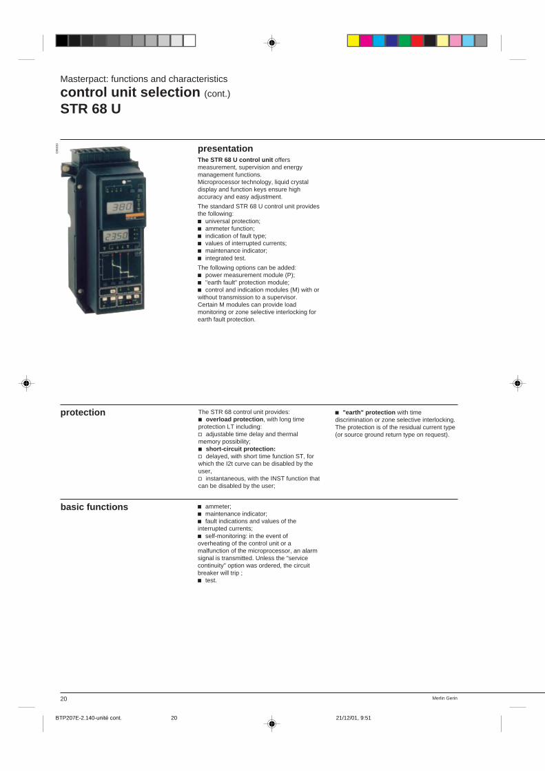
STR 68 U
presentationThe STR 68 U control unit offersmeasurement, supervision and energymanagement functions.Microprocessor technology, liquid crystaldisplay and function keys ensure highaccuracy and easy adjustment.
The standard STR 68 U control unit providesthe following:c universal protection;c ammeter function;c indication of fault type;c values of interrupted currents;c maintenance indicator;c integrated test.
The following options can be added:c power measurement module (P);c "earth fault" protection module;c control and indication modules (M) with orwithout transmission to a supervisor.Certain M modules can provide loadmonitoring or zone selective interlocking forearth fault protection.
The STR 68 control unit provides:c overload protection , with long timeprotection LT including:v adjustable time delay and thermalmemory possibility;c short-circuit protection:v delayed, with short time function ST, forwhich the I2t curve can be disabled by theuser,v instantaneous, with the INST function thatcan be disabled by the user;
protection
0366
30
c "earth" protection with timediscrimination or zone selective interlocking.The protection is of the residual current type(or source ground return type on request).
basic functions c ammeter;c maintenance indicator;c fault indications and values of theinterrupted currents;c self-monitoring: in the event ofoverheating of the control unit or amalfunction of the microprocessor, an alarmsignal is transmitted. Unless the "servicecontinuity" option was ordered, the circuitbreaker will trip ;c test.
BTP207E-2.140-unité cont. 21/12/01, 9:5120

21Merlin Gerin
optional functions c power measurement (P);c indication and control (M)Thirty-one different modules offer variouscombinations of functions including:v load monitoring,v trip indication,v self-monitoring,v zone selective interlocking for "earth fault"protection,v transmission of data to a supervisor(modules M17 to M31 only).Each STR 68 U control unit can be equippedwith only one M module.For the function offered by each M module,(see page xxx).
c "earth fault" protection (T)Of the residual current type (or sourceground return type on request), it is possibleto obtain zone selective interlocking bycombining the T option with the appropriateM option.
BTP207E-2.140-unité cont. 21/12/01, 9:5121
Merlin Gerin22
Masterpact: functions and characteristics
control unit selection (cont.)
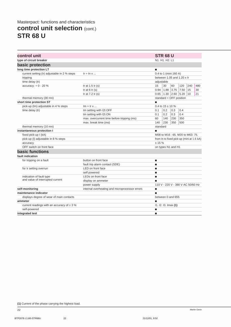
STR 68 U
control unit STR 68 Utype of circuit breaker N1. H1. H2. L1
basic protectionlong time protection LT c
current setting (Ir) adjustable in 2 % steps Ir = In x ... 0.4 to 1 (mini 160 A)tripping between 1.05 and 1.20 x Irtime delay (tr) adjustableaccuracy: + 0 - 20 % tr at 1.5 Ir (s) 15 30 60 120 240 480
tr at 6 Ir (s) 0.94 1.88 3.75 7.50 15 30tr at 7.2 Ir (s) 0.65 1.30 2.60 5.20 10 21
thermal memory (30 mn) standard + OFF positionshort time protection ST c
pick-up (Im) adjustable in 4 % steps Im = Ir x ... 0.4 to 15 ± 10 %time delay (tr) tm setting with I2t OFF 0.1 0.2 0.3 0.4
tm setting with I2t ON 0.1 0.2 0.3 0.4max. overcurrent time before tripping (ms) 60 140 230 350max. break time (ms) 140 230 350 500
thermal memory (10 mn) standardinstantaneous protection I c
fixed pick-up I (kA) M08 to M16 : 65. M20 to M63: 75.pick-up (I) adjustable in 8 % steps from In to fixed pick-up (mini at 1.6 kA)accuracy ± 15 %OFF switch on front face on types N1 and H1
basic functionsfault indication
for tripping on a fault button on front face cfault trip alarm contact (SDE) c
for Ir setting overrun LED on front face cself powered c
indication of fault type LEDs on front face cand value of interrupted current display on ammeter c
power supply 110 V - 220 V - 380 V AC 50/60 Hzself-monitoring internal overheating and microprocessor errors cmaintenance indicator c
displays degree of wear of main contacts between 0 and 655ammeter c
current readings with an accuracy of ± 3 % I1. I2. I3. Imax (1)self-powered c
integrated test c
(1) Current of the phase carrying the highest load.
BTP207E-2.160-STR68U 21/12/01, 9:5222
23Merlin Gerin
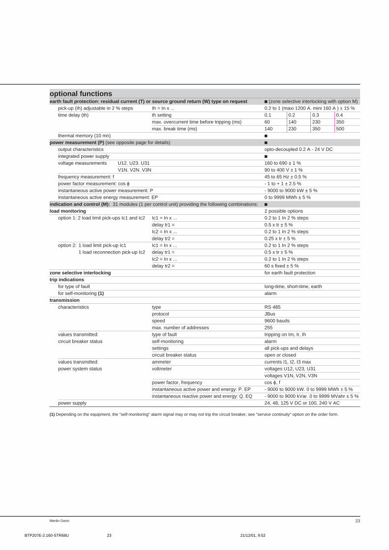
optional functionsearth fault protection: residual current (T) or source ground return (W) type on request c (zone selective interlocking with option M)
pick-up (Ih) adjustable in 2 % steps Ih = In x ... 0.2 to 1 (maxi 1200 A. mini 160 A ) ± 15 %time delay (th) th setting 0.1 0.2 0.3 0.4
max. overcurrent time before tripping (ms) 60 140 230 350max. break time (ms) 140 230 350 500
thermal memory (10 mn) cpower measurement (P) (see opposite page for details) c
output characteristics opto-decoupled 0.2 A - 24 V DCintegrated power supply cvoltage measurements U12. U23. U31 160 to 690 ± 1 %
V1N. V2N. V3N 90 to 400 V ± 1 %frequency measurement: f 45 to 65 Hz ± 0.5 %power factor measurement: cos ϕ - 1 to + 1 ± 2.5 %instantaneous active power measurement: P - 9000 to 9000 kW ± 5 %instantaneous active energy measurement: EP 0 to 9999 MWh ± 5 %
indication and control (M): 31 modules (1 per control unit) providing the following combinations: cload monitoring 2 possible options
option 1: 2 load limit pick-ups Ic1 and Ic2 Ic1 = In x ... 0.2 to 1 In 2 % stepsdelay tr1 = 0.5 x tr ± 5 %Ic2 = In x ... 0.2 to 1 In 2 % stepsdelay tr2 = 0.25 x tr ± 5 %
option 2: 1 load limit pick-up Ic1 Ic1 = In x ... 0.2 to 1 In 2 % steps1 load reconnection pick-up Ic2 delay tr1 = 0.5 x tr ± 5 %
Ic2 = In x ... 0.2 to 1 In 2 % stepsdelay tr2 = 60 s fixed ± 5 %
zone selective interlocking for earth fault protectiontrip indications
for type of fault long-time, short-time, earthfor self-monitoring (1) alarm
transmissioncharacteristics type RS 485
protocol JBusspeed 9600 baudsmax. number of addresses 255
values transmitted: type of fault tripping on Im, Ir, Ihcircuit breaker status self-monitoring alarm
settings all pick-ups and delayscircuit breaker status open or closed
values transmitted: ammeter currents I1, I2, I3 maxpower system status voltmeter voltages U12, U23, U31
voltages V1N, V2N, V3Npower factor, frequency cos ϕ, finstantaneous active power and energy: P. EP - 9000 to 9000 kW. 0 to 9999 MWh ± 5 %instantaneous reactive power and energy: Q. EQ - 9000 to 9000 kVar. 0 to 9999 MVahr ± 5 %
power supply 24, 48, 125 V DC or 100, 240 V AC
(1) Depending on the equipment, the "self-monitoring" alarm signal may or may not trip the circuit breaker, see "service continuity" option on the order form.
BTP207E-2.160-STR68U 21/12/01, 9:5223
Merlin Gerin24
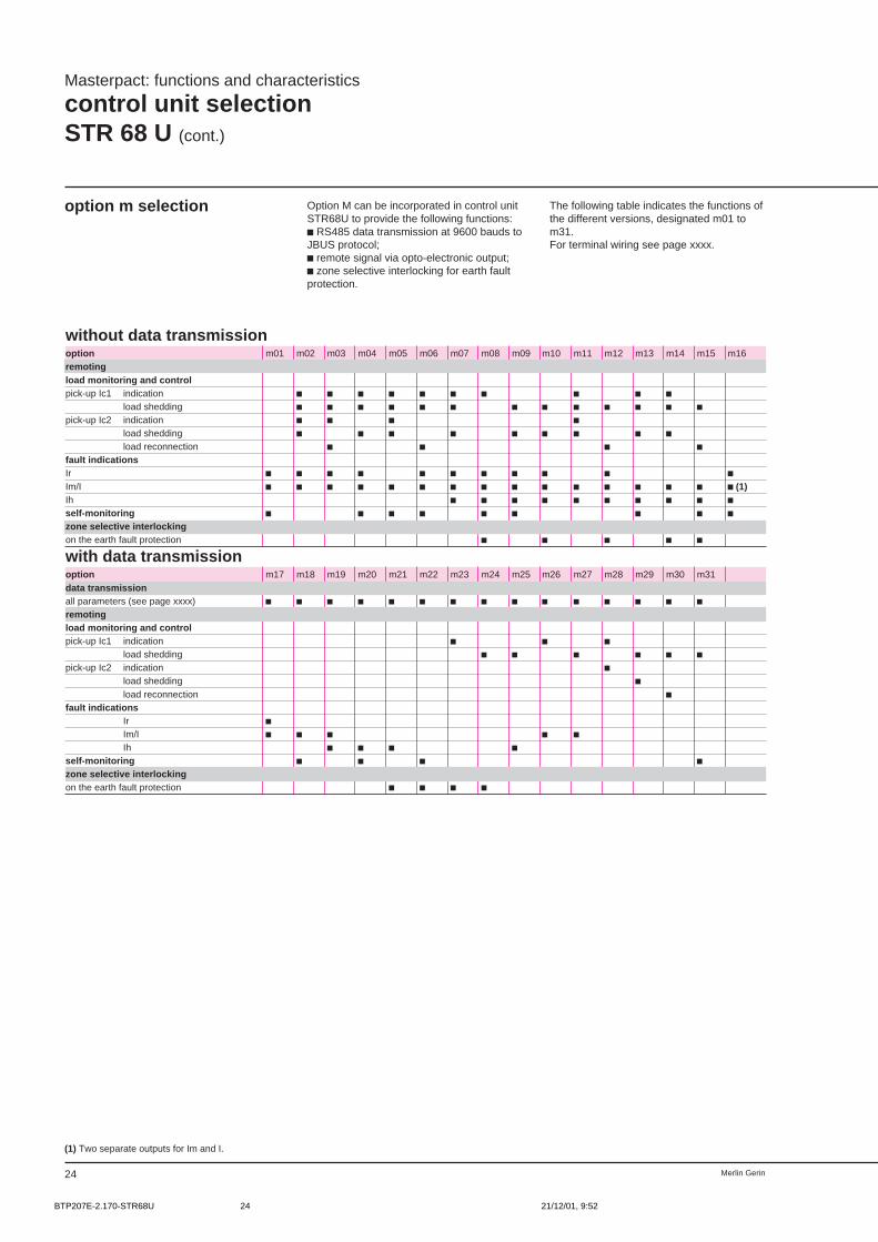
option m selection Option M can be incorporated in control unitSTR68U to provide the following functions:c RS485 data transmission at 9600 bauds toJBUS protocol;c remote signal via opto-electronic output;c zone selective interlocking for earth faultprotection.
The following table indicates the functions ofthe different versions, designated m01 tom31.For terminal wiring see page xxxx.
without data transmissionoption m01 m02 m03 m04 m05 m06 m07 m08 m09 m10 m11 m12 m13 m14 m15 m16remotingload monitoring and controlpick-up Ic1 indication c c c c c c c c c c
load shedding c c c c c c c c c c c c cpick-up Ic2 indication c c c c
load shedding c c c c c c c c cload reconnection c c c c
fault indicationsIr c c c c c c c c c c cIm/I c c c c c c c c c c c c c c c c (1)Ih c c c c c c c c c cself-monitoring c c c c c c c c czone selective interlockingon the earth fault protection c c c c c
with data transmissionoption m17 m18 m19 m20 m21 m22 m23 m24 m25 m26 m27 m28 m29 m30 m31data transmissionall parameters (see page xxxx) c c c c c c c c c c c c c c cremotingload monitoring and controlpick-up Ic1 indication c c c
load shedding c c c c c cpick-up Ic2 indication c
load shedding cload reconnection c
fault indicationsIr cIm/I c c c c cIh c c c c
self-monitoring c c c czone selective interlockingon the earth fault protection c c c c
Masterpact: functions and characteristics
control unit selectionSTR 68 U (cont.)
(1) Two separate outputs for Im and I.
BTP207E-2.170-STR68U 21/12/01, 9:5224
25Merlin Gerin
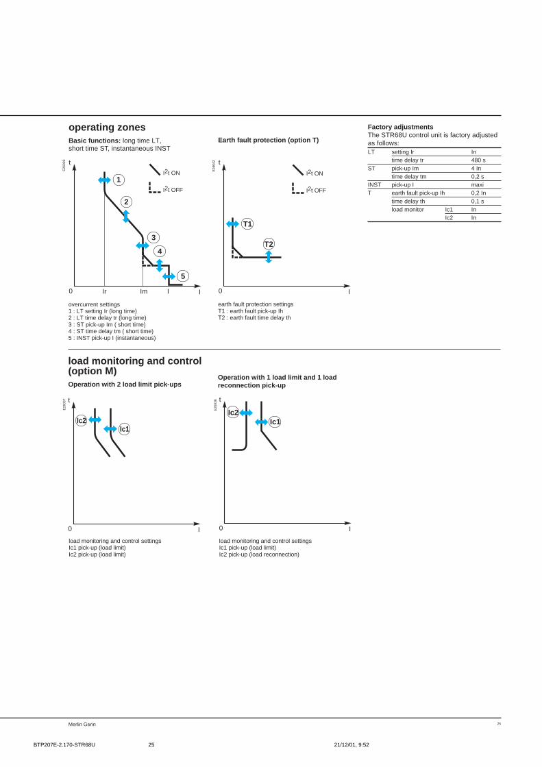
Factory adjustmentsThe STR68U control unit is factory adjustedas follows:LT setting Ir In
time delay tr 480 sST pick-up Im 4 In
time delay tm 0,2 sINST pick-up I maxiT earth fault pick-up Ih 0,2 In
time delay th 0,1 sload monitor Ic1 In
Ic2 In
Earth fault protection (option T)
operating zonesBasic functions: long time LT,short time ST, instantaneous INST
2
5
Ir Im
3
I I
t
0
1
4
I2t ON
I2t OFF
I
t
0
T1
T2
I2t ON
I2t OFF
overcurrent settings1 : LT setting Ir (long time)2 : LT time delay tr (long time)3 : ST pick-up Im ( short time)4 : ST time delay tm ( short time)5 : INST pick-up I (instantaneous)
earth fault protection settingsT1 : earth fault pick-up IhT2 : earth fault time delay th
load monitoring and control(option M)Operation with 2 load limit pick-ups
I
t
0
Ic2Ic1
I
t
0
Ic2Ic1
load monitoring and control settingsIc1 pick-up (load limit)Ic2 pick-up (load limit)
load monitoring and control settingsIc1 pick-up (load limit)Ic2 pick-up (load reconnection)
Operation with 1 load limit and 1 loadreconnection pick-up
E26
037
E26
038
E26
039
E26
042
BTP207E-2.170-STR68U 21/12/01, 9:5225
Merlin Gerin26
Masterpact: functions and characteristics
control unit accessories
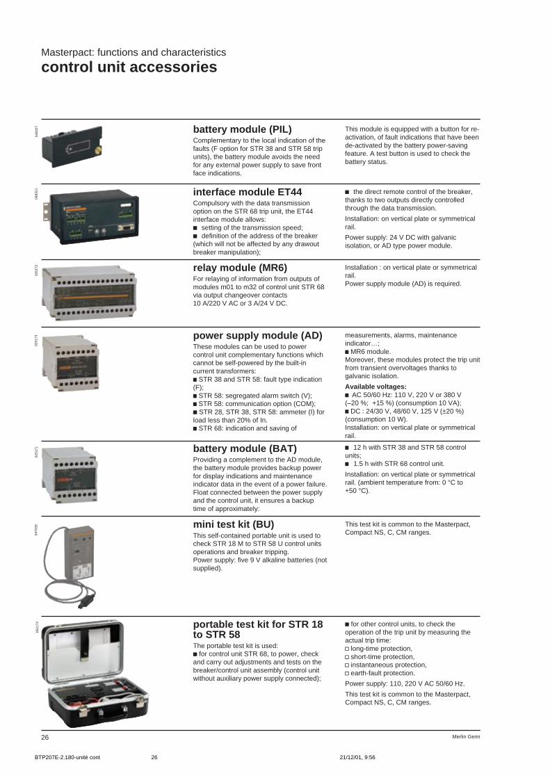
battery module (PIL)Complementary to the local indication of thefaults (F option for STR 38 and STR 58 tripunits), the battery module avoids the needfor any external power supply to save frontface indications.
This module is equipped with a button for re-activation, of fault indications that have beende-activated by the battery power-savingfeature. A test button is used to check thebattery status.
interface module ET44Compulsory with the data transmissionoption on the STR 68 trip unit, the ET44interface module allows:c setting of the transmission speed;c definition of the address of the breaker(which will not be affected by any drawoutbreaker manipulation);
c the direct remote control of the breaker,thanks to two outputs directly controlledthrough the data transmission.
Installation: on vertical plate or symmetricalrail.
Power supply: 24 V DC with galvanicisolation, or AD type power module.
0483
2704
8321
relay module (MR6)For relaying of information from outputs ofmodules m01 to m32 of control unit STR 68via output changeover contacts10 A/220 V AC or 3 A/24 V DC.
Installation : on vertical plate or symmetricalrail.Power supply module (AD) is required.
0251
72
power supply module (AD)These modules can be used to powercontrol unit complementary functions whichcannot be self-powered by the built-incurrent transformers:c STR 38 and STR 58: fault type indication(F);c STR 58: segregated alarm switch (V);c STR 58: communication option (COM);c STR 28, STR 38, STR 58: ammeter (I) forload less than 20% of In.c STR 68: indication and saving of
0251
73 measurements, alarms, maintenanceindicator…;c MR6 module.Moreover, these modules protect the trip unitfrom transient overvoltages thanks togalvanic isolation.
Available voltages:c AC 50/60 Hz: 110 V, 220 V or 380 V(–20 %; +15 %) (consumption 10 VA);c DC : 24/30 V, 48/60 V, 125 V (±20 %)(consumption 10 W).Installation: on vertical plate or symmetricalrail.
0470
3505
2172
battery module (BAT)Providing a complement to the AD module,the battery module provides backup powerfor display indications and maintenanceindicator data in the event of a power failure.Float connected between the power supplyand the control unit, it ensures a backuptime of approximately:
c 12 h with STR 38 and STR 58 controlunits;c 1.5 h with STR 68 control unit.
Installation: on vertical plate or symmetricalrail. (ambient temperature from: 0 °C to+50 °C).
mini test kit (BU)This self-contained portable unit is used tocheck STR 18 M to STR 58 U control unitsoperations and breaker tripping.Power supply: five 9 V alkaline batteries (notsupplied).
This test kit is common to the Masterpact,Compact NS, C, CM ranges.
0251
71
portable test kit for STR 18to STR 58The portable test kit is used:c for control unit STR 68, to power, checkand carry out adjustments and tests on thebreaker/control unit assembly (control unitwithout auxiliary power supply connected);
c for other control units, to check theoperation of the trip unit by measuring theactual trip time:v long-time protection,v short-time protection,v instantaneous protection,v earth-fault protection.
Power supply: 110, 220 V AC 50/60 Hz.
This test kit is common to the Masterpact,Compact NS, C, CM ranges.
BTP207E-2.180-unité cont 21/12/01, 9:5626
27Merlin Gerin
Masterpact: functions and characteristics
auxiliary power supplies
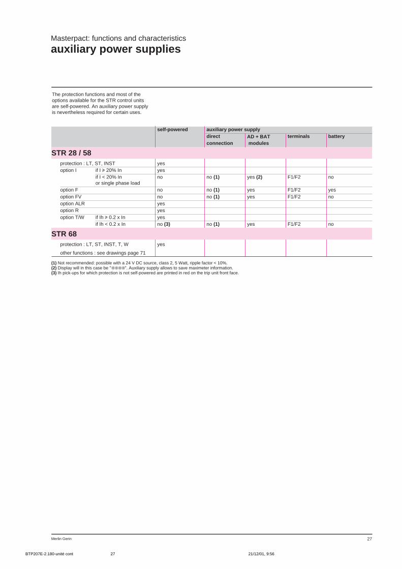
The protection functions and most of theoptions available for the STR control unitsare self-powered. An auxiliary power supplyis nevertheless required for certain uses.
(1) Not recommended: possible with a 24 V DC source, class 2, 5 Watt, ripple factor < 10%.(2) Display will in this case be "". Auxiliary supply allows to save maximeter information.(3) Ih pick-ups for which protection is not self-powered are printed in red on the trip unit front face.
self-powered auxiliary power supplydirect AD + BAT terminals batteryconnection modules
STR 28 / 58protection : LT, ST, INST yesoption I if I u 20% In yes
if I < 20% In no no (1) yes (2) F1/F2 noor single phase load
option F no no (1) yes F1/F2 yesoption FV no no (1) yes F1/F2 nooption ALR yesoption R yesoption T/W if Ih u 0.2 x In yes
if Ih < 0.2 x In no (3) no (1) yes F1/F2 no
STR 68protection : LT, ST, INST, T, W yes
other functions : see drawings page 71
BTP207E-2.180-unité cont 21/12/01, 9:5627

Merlin Gerin14
Masterpact: functions and characteristics
auxiliaries
electrical operatingmechanismAdded to the manual charging mechanism,a motor charges and automaticallyrecharges the stored-energy spring uponbreaker closing making possible fastO-C-O cycles.Opening and closing operations areinstantaneous.The manual mechanism remains availablefor emergency use.
The electrical operating mechanismincludes:c the gear motor(MCH);c a closing release (XF);c a shunt release (MX) or an undervoltagerelease (MN) for opening;c "springs charged" limit switch changeovercontact (CH).The addition of the electrical operatingmechanism does not alter circuit breakerdimensions.
characteristics geared motor MCHpower supply 50/60 Hz (V) 100/127 - 200/240 - 250/277 - 380 - 415 - 440 - 480
consumption (VA) 180DC (V) 24/30 - 48/60 - 100/125 - 200/250 consumption (W) 180
motor start-up surge 2 to 3 In for 0.1 scharging time 3 to 4 s
0132
82
BTP207E-2.202-circuit-breaker 21/12/01, 9:5814

15Merlin Gerin
operation counter(CDM)With gear-motor option only. The operationcounter is read from the front and gives thetotal number of breaker operating cycles.
0359
32
BTP207E-2.202-circuit-breaker 21/12/01, 9:5815
Merlin Gerin16
Masterpact: functions and characteristics
auxiliaries (cont.)
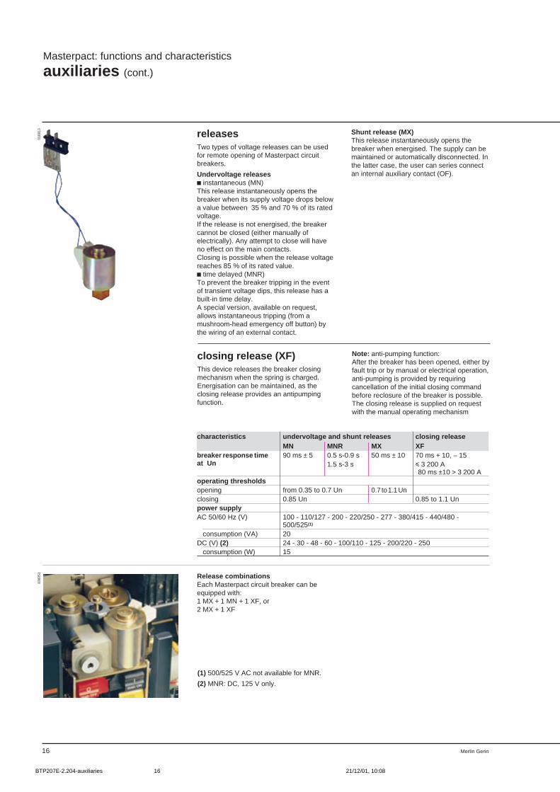
Shunt release (MX)This release instantaneously opens thebreaker when energised. The supply can bemaintained or automatically disconnected. Inthe latter case, the user can series connectan internal auxiliary contact (OF).
releasesTwo types of voltage releases can be usedfor remote opening of Masterpact circuitbreakers.
Undervoltage releasesc instantaneous (MN)This release instantaneously opens thebreaker when its supply voltage drops belowa value between 35 % and 70 % of its ratedvoltage.If the release is not energised, the breakercannot be closed (either manually ofelectrically). Any attempt to close will haveno effect on the main contacts.Closing is possible when the release voltagereaches 85 % of its rated value.c time delayed (MNR)To prevent the breaker tripping in the eventof transient voltage dips, this release has abuilt-in time delay.A special version, available on request,allows instantaneous tripping (from amushroom-head emergency off button) bythe wiring of an external contact.
closing release (XF)This device releases the breaker closingmechanism when the spring is charged.Energisation can be maintained, as theclosing release provides an antipumpingfunction.
Note: anti-pumping function:After the breaker has been opened, either byfault trip or by manual or electrical operation,anti-pumping is provided by requiringcancellation of the initial closing commandbefore reclosure of the breaker is possible.The closing release is supplied on requestwith the manual operating mechanism
(1) 500/525 V AC not available for MNR.
(2) MNR: DC, 125 V only.
0168
1303
6051 Release combinations
Each Masterpact circuit breaker can beequipped with:1 MX + 1 MN + 1 XF, or2 MX + 1 XF
characteristics undervoltage and shunt releases closing releaseMN MNR MX XF
breaker response time 90 ms ± 5 0.5 s-0.9 s 50 ms ± 10 70 ms + 10, – 15at Un 1.5 s-3 s i 3 200 A
80 ms ±10 > 3 200 Aoperating thresholdsopening from 0.35 to 0.7 Un 0.7 to 1.1 Unclosing 0.85 Un 0.85 to 1.1 Unpower supplyAC 50/60 Hz (V) 100 - 110/127 - 200 - 220/250 - 277 - 380/415 - 440/480 -
500/525(1)
consumption (VA) 20DC (V) (2) 24 - 30 - 48 - 60 - 100/110 - 125 - 200/220 - 250 consumption (W) 15
BTP207E-2.204-auxiliaries 21/12/01, 10:0816
17Merlin Gerin
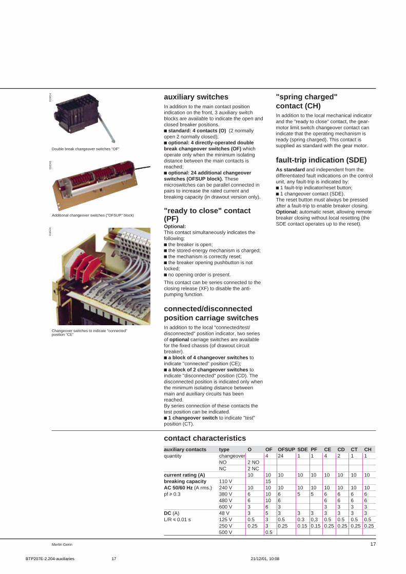
Changeover switches to indicate "connected"position "CE"
Double break changeover switches "OF"
auxiliary switchesIn addition to the main contact positionindication on the front, 3 auxiliary switchblocks are available to indicate the open andclosed breaker positions.c standard: 4 contacts (O) (2 normallyopen 2 normally closed);c optional: 4 directly-operated doublebreak changeover switches (OF) whichoperate only when the minimum isolatingdistance between the main contacts isreached;c optional: 24 additional changeoverswitches (OFSUP block). Thesemicroswitches can be parallel connected inpairs to increase the rated current andbreaking capacity (in drawout version only).
"ready to close" contact(PF)Optional:This contact simultaneously indicates thefollowing:c the breaker is open;c the stored-energy mechanism is charged;c the mechanism is correctly reset;c the breaker opening pushbutton is notlocked;c no opening order is present.
This contact can be series connected to theclosing release (XF) to disable the anti-pumping function.
connected/disconnectedposition carriage switchesIn addition to the local "connected/test/disconnected" position indicator, two seriesof optional carriage switches are availablefor the fixed chassis (of drawout circuitbreaker).c a block of 4 changeover switches toindicate "connected" position (CE);c a block of 2 changeover switches toindicate "disconnected" position (CD). Thedisconnected position is indicated only whenthe minimum isolating distance betweenmain and auxiliary circuits has beenreached.By series connection of these contacts thetest position can be indicated.c 1 changeover switch to indicate "test"position (CT).
contact characteristics
"spring charged"contact (CH)In addition to the local mechanical indicatorand the "ready to close" contact, the gear-motor limit switch changeover contact canindicate that the operating mechanism isready (spring charged). This contact issupplied as standard with the gear motor.
fault-trip indication (SDE)As standard and independent from thedifferentiated fault indications on the controlunit, any fault-trip is indicated by:c 1 fault-trip indicator/reset button;c 1 changeover contact (SDE).The reset button must always be pressedafter a fault-trip to enable breaker closing.Optional: automatic reset, allowing remotebreaker closing without local resetting (theSDE contact operates up to the reset).
auxiliary contacts type O OF OFSUP SDE PF CE CD CT CHquantity changeover 4 24 1 1 4 2 1 1
NO 2 NONC 2 NC
current rating (A) 10 10 10 10 10 10 10 10 10breaking capacity 110 V 15AC 50/60 Hz (A rms.) 240 V 10 10 10 10 10 10 10 10 10pf u 0.3 380 V 6 10 6 5 5 6 6 6 6
480 V 6 10 6 6 6 6 6600 V 3 6 3 3 3 3 3
DC (A) 48 V 3 5 3 3 3 3 3 3 3L/R i 0.01 s 125 V 0.5 3 0.5 0.3 0,3 0.5 0.5 0.5 0.5
250 V 0.25 3 0.25 0.15 0.15 0.25 0.25 0.25 0.25500 V 0.5
0168
1401
8242
0165
24
Additional changeover switches ("OFSUP" block)
BTP207E-2.204-auxiliaries 21/12/01, 10:0817
Merlin Gerin18
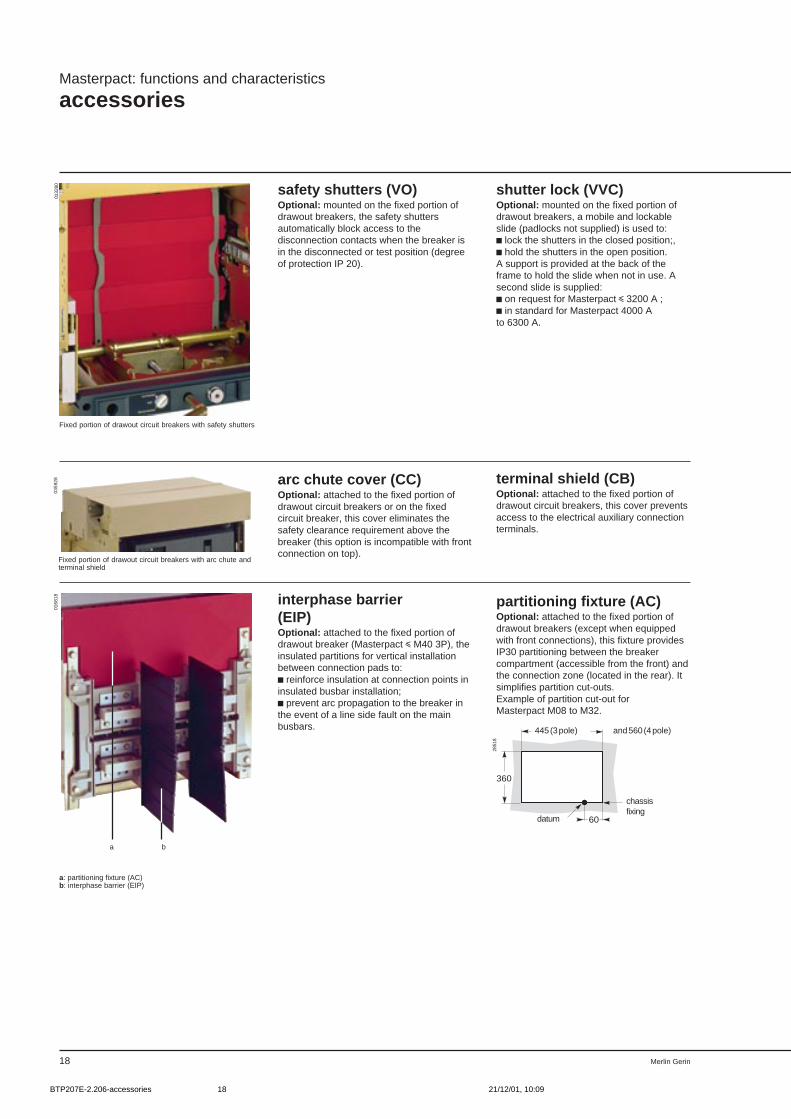
a: partitioning fixture (AC)b: interphase barrier (EIP)
Fixed portion of drawout circuit breakers with arc chute andterminal shield
0359
28
Fixed portion of drawout circuit breakers with safety shutters
safety shutters (VO)Optional: mounted on the fixed portion ofdrawout breakers, the safety shuttersautomatically block access to thedisconnection contacts when the breaker isin the disconnected or test position (degreeof protection IP 20).
Masterpact: functions and characteristics
accessories
terminal shield (CB)Optional: attached to the fixed portion ofdrawout circuit breakers, this cover preventsaccess to the electrical auxiliary connectionterminals.
arc chute cover (CC)Optional: attached to the fixed portion ofdrawout circuit breakers or on the fixedcircuit breaker, this cover eliminates thesafety clearance requirement above thebreaker (this option is incompatible with frontconnection on top).
interphase barrier(EIP)Optional: attached to the fixed portion ofdrawout breaker (Masterpact i M40 3P), theinsulated partitions for vertical installationbetween connection pads to:c reinforce insulation at connection points ininsulated busbar installation;c prevent arc propagation to the breaker inthe event of a line side fault on the mainbusbars.
partitioning fixture (AC)Optional: attached to the fixed portion ofdrawout breakers (except when equippedwith front connections), this fixture providesIP30 partitioning between the breakercompartment (accessible from the front) andthe connection zone (located in the rear). Itsimplifies partition cut-outs.Example of partition cut-out forMasterpact M08 to M32.
shutter lock (VVC)Optional: mounted on the fixed portion ofdrawout breakers, a mobile and lockableslide (padlocks not supplied) is used to:c lock the shutters in the closed position;,c hold the shutters in the open position.A support is provided at the back of theframe to hold the slide when not in use. Asecond slide is supplied:c on request for Masterpact i 3200 A ;c in standard for Masterpact 4000 Ato 6300 A.
360
445 (3 pôles) et 560 (4 pôles)
60
plan de fixationchâssis
référence
445 (3 pole) and 560 (4 pole)
chassisfixing
datum
0168
1801
3280
a b
2851
8
BTP207E-2.206-accessories 21/12/01, 10:0918
19Merlin Gerin
Auxiliaries for drawout version
Auxiliaries for fixed version
0168
14
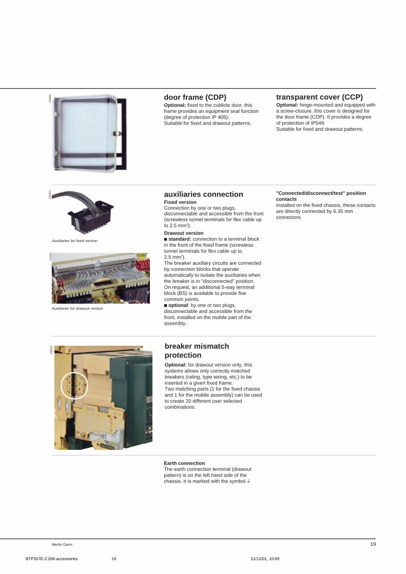
door frame (CDP)Optional: fixed to the cublicle door, thisframe provides an equipment seal function(degree of protection IP 405).Suitable for fixed and drawout patterns.
Earth connectionThe earth connection terminal (drawoutpattern) is on the left hand side of thechassis. It is marked with the symbol t
transparent cover (CCP)Optional: hinge-mounted and equipped witha screw-closure, this cover is designed forthe door frame (CDP). It provides a degreeof protection of IP549.Suitable for fixed and drawout patterns.
0168
19
auxiliaries connectionFixed versionConnection by one or two plugs,disconnectable and accessible from the front(screwless tunnel terminals for flex cable upto 2.5 mm2).
Drawout versionc standard: connection to a terminal blockin the front of the fixed frame (screwlesstunnel terminals for flex cable up to2.5 mm2).The breaker auxiliary circuits are connectedby connection blocks that operateautomatically to isolate the auxiliaries whenthe breaker is in "disconnected" position.On request, an additional 5-way terminalblock (BS) is available to provide fivecommon points.c optional : by one or two plugs,disconnectable and accessible from thefront, installed on the mobile part of theassembly.
"Connected/disconnect/test" positioncontactsInstalled on the fixed chassis, these contactsare directly connected by 6.35 mmconnectors.
0155
61
breaker mismatchprotectionOptional: for drawout version only, thissystems allows only correctly matchedbreakers (rating, type wiring, etc.) to beinserted in a given fixed frame.Two matching parts (1 for the fixed chassisand 1 for the mobile assembly) can be usedto create 20 different user selectedcombinations.
0359
40
BTP207E-2.206-accessories 21/12/01, 10:0919
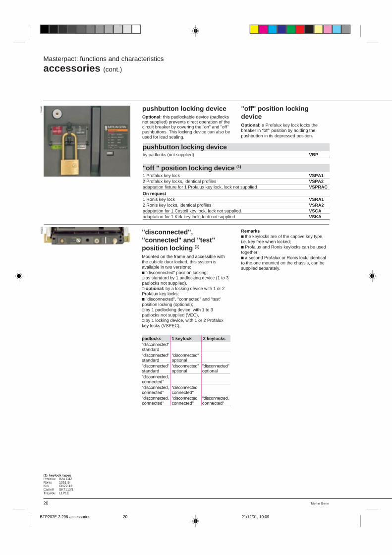
Merlin Gerin20
"disconnected","connected" and "test"position locking (1)
Mounted on the frame and accessible withthe cubicle door locked, this system isavailable in two versions:c "disconnected" position locking;v as standard by 1 padlocking device (1 to 3padlocks not supplied),v optional: by a locking device with 1 or 2Profalux key locks;c "disconnected", "connected" and "test"position locking (optional);v by 1 padlocking device, with 1 to 3padlocks not supplied (VEC),v by 1 locking device, with 1 or 2 Profaluxkey locks (VSPEC),
padlocks 1 keylock 2 keylocks"disconnected"standard"disconnected" "disconnected"standard optional"disconnected" "disconnected" "disconnected"standard optional optional"disconnected,connected""disconnected, "disconnected,connected" connected""disconnected, "disconnected, "disconnected,connected" connected" connected"
pushbutton locking deviceOptional: this padlockable device (padlocksnot supplied) prevents direct operation of thecircuit breaker by covering the "on" and "off"pushbuttons. This locking device can also beused for lead sealing.
Masterpact: functions and characteristics
accessories (cont.)
(1) keylock typesProfalux B24 D4ZRonis 1351 BKirk CN22-12Castell SK7113/1Trayvou L1P1E
"off" position lockingdeviceOptional: a Profalux key lock locks thebreaker in "off" position by holding thepushbutton in its depressed position.
pushbutton locking deviceby padlocks (not supplied) VBP
"off " position locking device (1)
1 Profalux key lock VSPA12 Profalux key locks, identical profiles VSPA2adaptation fixture for 1 Profalux key lock, lock not supplied VSPRACOn request1 Ronis key lock VSRA12 Ronis key locks, identical profiles VSRA2adaptation for 1 Castell key lock, lock not supplied VSCAadaptation for 1 Kirk key lock, lock not supplied VSKA
Remarksc the keylocks are of the captive key type,i.e. key free when locked;c Profalux and Ronis keylocks can be usedtogether;c a second Profalux or Ronis lock, identicalto the one mounted on the chassis, can besupplied separately.
0359
3203
5931
BTP207E-2.208-accessories 21/12/01, 10:0920
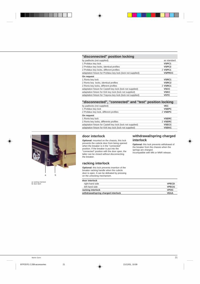
21Merlin Gerin
0168
17
"disconnected" position lockingby padlocks (not supplied) as standard1 Profalux key lock VSPC12 Profalux key locks, identical profiles VSPC22 Profalux key locks, different profiles 2 VSPC1adaptation fixture for Profalux key lock (lock not supplied) VSPRCC
On request1 Ronis key lock VSRC12 Ronis key locks, identical profiles VSRC22 Ronis key locks, different profiles 2 VSRC1adaptation fixture for Castell key lock (lock not supplied) VSCCadaptation fixture for Kirk key lock (lock not supplied) VSKCadaptation fixture for Trayvou key lock (lock not supplied) VSTC
"disconnected", "connected" and "test" position lockingby padlocks (not supplied) VEC1 Profalux key lock VSEPC2 Profalux key lock, different profiles 2 VSEPC
On request1 Ronis key lock VSERC2 Ronis key locks, differents profiles 2 VSERCadaptation fixture for Castell key lock (lock not supplied) VSECCadaptation fixture for Kirk key lock (lock not supplied) VSEKC
door interlockOptional: mounted on the chassis, this lockprevents the cubicle door from being openedwhen the breaker is in the "connected"position. If the breaker is put into the"connected" position with the door open, thelatter can be closed without disconnectingthe breaker.
racking interlockOptional: this lock prevents insertion of thebreaker racking handle when the cubicledoor is open. It can be defeated by pressingon the unlocking mechanism.
withdrawal/spring chargedinterlockOptional: this lock prevents withdrawal ofthe breaker from the chassis when thesprings are charged.Incompatible with MN or MNR release.
a: racking interlockb: door latch
door interlock right-hand side VPECD left-hand side VPECGracking interlock VPOCwithdrawal/spring charged interlock VEAA
a b
BTP207E-2.208-accessories 21/12/01, 10:0921
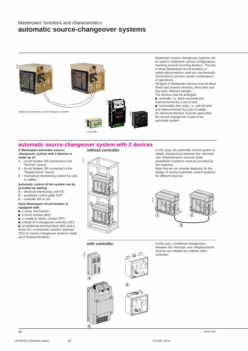
Merlin Gerin36
Masterpact: functions and characteristics
automatic source-changeover systems
Masterpact source-changeover systems canbe used to implement various configurationsinvolving several incoming feeders. The twoor three Masterpact circuit breakers orswitch-disconnectors used are mechanicallyinterlocked to prevent certain combinationsof operations.All types of Masterpact devices may be fitted(fixed and drawout versions, three-pole andfour-pole, different ratings).The devices may be arranged:c vertically, i.e. stack-mounted andinterconnected by a set of rods;c horizontally (two only), i.e. side-by-sideand interconnected by a set of cables.An electrical interlock must be used whenthe source changeover is part of anautomatic system.
E33
079
E33
078
R
N
N
R
auto
stop
manu
UN
ON / I
OFF / O
fault
UR
ON / I
OFF / O
fault
UN = O
UN = 1
MERLIN GERIN
STOP generator
N
R
test
BU
S
Test
MERLIN GERIN
multi 9
P25M
660V
AC3-IEC292-1
0 . OFF
Test
MERLIN GERIN
multi 9
P25M
660V
AC3-IEC292-1
0 . OFF
4
5
6
R
N
N
0,5s
R
0,5s
UN
ON / I
OFF / O
fault
UR
ON / I
OFF / O
fault
UN = O
UN = 1
MERLIN GERIN
stop
manu
N
test
R
E33
082
automatic source-changeover system with 2 devices
1
2
3
3
1 2
3
with controller In this case, conditional changeoversbetween the «Normal» and «Replacement»sources are initiated by a Merlin Gerincontroller.
A Masterpact automatic source-changeover system with 2 devices ismade up of:1 - circuit breaker QN connected to the
"Normal" source;2 - circuit breaker QR connected to the
"Replacement" source;3 - mechanical interlocking system by rods
or cables;
automatic control of the system can beprovided by adding:4 - electrical interlocking unit IVE;5 - auxiliaries control plate ACP;6 - controller BA or UA.
Each Masterpact circuit breaker isequipped with:c a motor mechanism;c a shunt release (MX);c a «ready to close» contact (PF);c a block of 4 changeover switches (OF);c an additional terminal block (BS) and ablock of 4 «connected» position switches(CE) for source-changeover systems madeup of drawout breakers.
without controller In this case, the automatic control system toinitiate changeovers between the «Normal»and «Replacement» sources underpredefined conditions must be provided bythe customer.Note that we can provide diagrams for thedesign of various automatic control systemsfor different sources.
Masterpact automatic source-changeover system
Controller
0251
86
0530
61
0530
60
0530
58
BTP207E-2.220-invers source 21/12/01, 10:1036
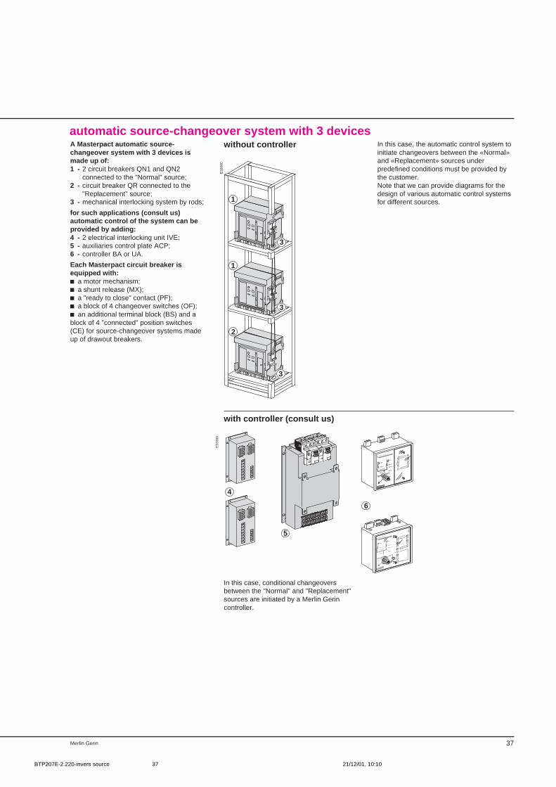
37Merlin Gerin
E33
080
1
1
2
3
3
3
automatic source-changeover system with 3 devicesA Masterpact automatic source-changeover system with 3 devices ismade up of:1 - 2 circuit breakers QN1 and QN2
connected to the "Normal" source;2 - circuit breaker QR connected to the
"Replacement" source;3 - mechanical interlocking system by rods;
for such applications (consult us)automatic control of the system can beprovided by adding:4 - 2 electrical interlocking unit IVE;5 - auxiliaries control plate ACP;6 - controller BA or UA.
Each Masterpact circuit breaker isequipped with:c a motor mechanism;c a shunt release (MX);c a "ready to close" contact (PF);c a block of 4 changeover switches (OF);c an additional terminal block (BS) and ablock of 4 "connected" position switches(CE) for source-changeover systems madeup of drawout breakers.
without controller In this case, the automatic control system toinitiate changeovers between the «Normal»and «Replacement» sources underpredefined conditions must be provided bythe customer.Note that we can provide diagrams for thedesign of various automatic control systemsfor different sources.
with controller (consult us)
E33
383
R
N
N
R
auto
stop
manu
UN
ON / I
OFF / O
fault
UR
ON / I
OFF / O
fault
UN = O
UN = 1
MERLIN GERIN
STOP generator
N
R
test
BU
S
Test
MERLIN GERIN
multi 9
P25M
660V
AC3-IEC292-1
0 . OFF
Test
MERLIN GERIN
multi 9
P25M
660V
AC3-IEC292-1
0 . OFF
4
5
6
R
N
N
0,5s
R
0,5s
UN
ON / I
OFF / O
fault
UR
ON / I
OFF / O
fault
UN = O
UN = 1
MERLIN GERIN
stop
manu
N
test
R
In this case, conditional changeoversbetween the "Normal" and "Replacement"sources are initiated by a Merlin Gerincontroller.
BTP207E-2.220-invers source 21/12/01, 10:1037
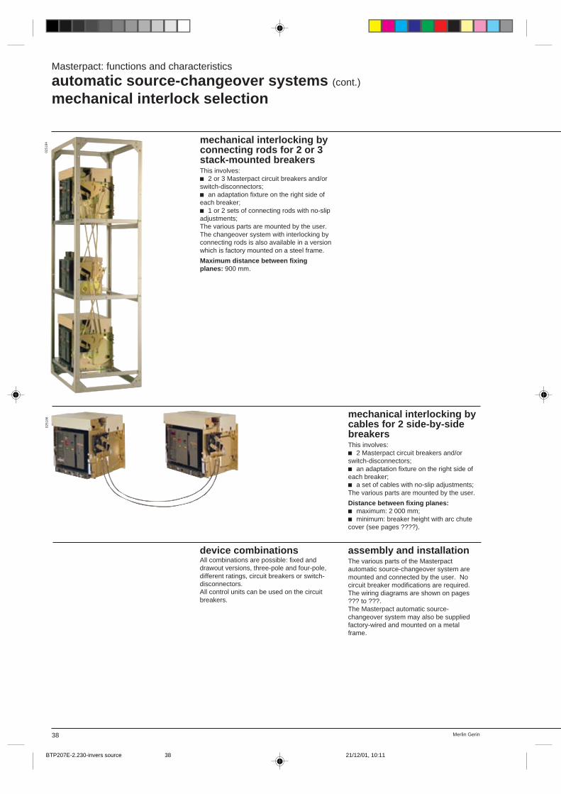
Merlin Gerin38
Masterpact: functions and characteristics
automatic source-changeover systems (cont.)
mechanical interlock selection
0251
8402
5186
mechanical interlocking byconnecting rods for 2 or 3stack-mounted breakersThis involves:c 2 or 3 Masterpact circuit breakers and/orswitch-disconnectors;c an adaptation fixture on the right side ofeach breaker;c 1 or 2 sets of connecting rods with no-slipadjustments;The various parts are mounted by the user.The changeover system with interlocking byconnecting rods is also available in a versionwhich is factory mounted on a steel frame.
Maximum distance between fixingplanes: 900 mm.
mechanical interlocking bycables for 2 side-by-sidebreakersThis involves:c 2 Masterpact circuit breakers and/orswitch-disconnectors;c an adaptation fixture on the right side ofeach breaker;c a set of cables with no-slip adjustments;The various parts are mounted by the user.
Distance between fixing planes:c maximum: 2 000 mm;c minimum: breaker height with arc chutecover (see pages ????).
device combinationsAll combinations are possible: fixed anddrawout versions, three-pole and four-pole,different ratings, circuit breakers or switch-disconnectors.All control units can be used on the circuitbreakers.
assembly and installationThe various parts of the Masterpactautomatic source-changeover system aremounted and connected by the user. Nocircuit breaker modifications are required.The wiring diagrams are shown on pages??? to ???.The Masterpact automatic source-changeover system may also be suppliedfactory-wired and mounted on a metalframe.
BTP207E-2.230-invers source 21/12/01, 10:1138
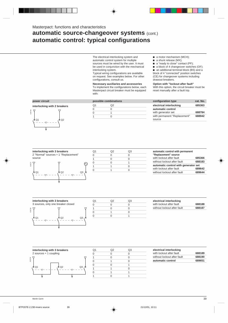
39Merlin Gerin
power circuit possible combinations configuration type cat. No.
interlocking with 3 breakers3 sources, only one breaker closed
interlocking with 3 breakers2 sources + 1 coupling
E30
737
E30
738
E30
739
electrical interlocking 685363automatic controlwith generator set 688784with permanent "Replacement" 688942source
interlocking with 2 breakers Q1 Q20 00 11 0
E30
736
Q1 Q2
Q1 Q2 Q3
Q1 Q2 Q3
Masterpact: functions and characteristics
automatic source-changeover systems (cont.)
automatic control: typical configurations
The electrical interlocking system andautomatic control system for multiplesources must be wired by the user. It mustbe used in conjunction with the mechanicalinterlocking system.Typical wiring configurations are availableon request. See examples below. For otherconfigurations, consult us.
Necessary auxiliaries and accessoriesTo implement the configurations below, eachMasterpact circuit breaker must be equippedwith:
c a motor mechanism (MCH);c a shunt release (MX);c a "ready to close" contact (PF);c a block of 4 changeover switches (OF);c an additional terminal block (BS) and ablock of 4 "connected" position switches(CE) for changeover systems includingdrawout breakers.
Option with "lockout after fault"With this option, the circuit breaker must bereset manually after a fault trip.
interlocking with 3 breakers2 "Normal" sources + 1 "Replacement"source
Q1 Q2 Q3
Q1 Q2 Q30 0 01 0 00 0 11 1 00 1 0
automatic control with permanent"Replacement" sourcewith lockout after fault 685366without lockout after fault 688183automatic control with generator setwith lockout after fault 689642without lockout after fault 689644
electrical interlockingwith lockout after fault 688188without lockout after fault 688187
Q1 Q2 Q30 0 01 0 00 1 00 0 1
Q1 Q2 Q30 0 01 0 00 1 00 0 11 1 00 1 11 0 1
electrical interlockingwith lockout after fault 688189without lockout after fault 688190automatic control 689651
BTP207E-2.230-invers source 21/12/01, 10:1139
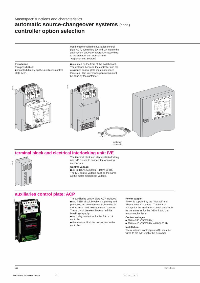
40 Merlin Gerin
Masterpact: functions and characteristics
automatic source-changeover systems (cont.)
controller option selection
Used together with the auxiliaries controlplate ACP, controllers BA and UA initiate theautomatic changeover operations accordingto the status of the "Normal" and"Replacement" sources.
E32
704
E32
705
E32
703
InstallationTwo possibilities:c mounted directly on the auxiliaries controlplate ACP.
c mounted on the front of the switchboard.The distance between the controller and theauxiliaries control plate must not exceed2 metres. The interconnection wiring mustbe done by the customer.
terminal block and electrical interlocking unit: IVE
R
N
N
R
auto
stop
manu
UN
ON / I
OFF / O
fault
UR
ON / I
OFF / O
fault
UN = O
UN = 1
MERLIN GERIN
STOP generator
N
R
test
BU
S
Test
MERLIN GERIN
multi 9
P25M
660V
AC3-IEC292-1
0 . OFF
Test
MERLIN GERIN
multi 9
P25M
660V
AC3-IEC292-1
0 . OFF
customerconnection
Test
MERLIN GERIN
multi 9
P25M
660V
AC3-IEC292-1
0 . OFF
Test
MERLIN GERIN
multi 9
P25M
660V
AC3-IEC292-1
0 . OFF
R
N
N
R
auto
stop
manu
UN
ON / I
OFF / O
fault
UR
ON / I
OFF / O
fault
UN = O
UN = 1
MERLIN GERIN
STOP generator
N
R
test
BU
S
The terminal block and electrical interlockingunit IVE is used to connect the operatingmechanism.
Control voltage:c 48 to 415 V, 50/60 Hz - 440 V 60 Hz.The IVE control voltage must be the sameas the motor mechanism voltage.
auxiliaries control plate: ACPThe auxiliaries control plate ACP includes:c two P25M circuit breakers supplying andprotecting the automatic control circuits forthe "Normal" and "Replacement" sources.These circuit breakers have an infinitebreaking capacity;c two relay contactors for the BA or UAcontroller;c the terminal block for connection to thecontroller.
Power supply:Power is supplied by the "Normal" and"Replacement" sources. The controlvoltage for the auxiliaries control plate mustbe the same as for the IVE unit and themotor mechanisms.
Control voltagesc 220 to 240 V 50/60 Hz;c 380 to 415 V 50/60 Hz - 440 V 60 Hz.
Installation:The auxiliaries control plate ACP must bewired to the IVE unit by the customer.
0530
60
BTP207E-2.240-invers source 21/12/01, 10:1240
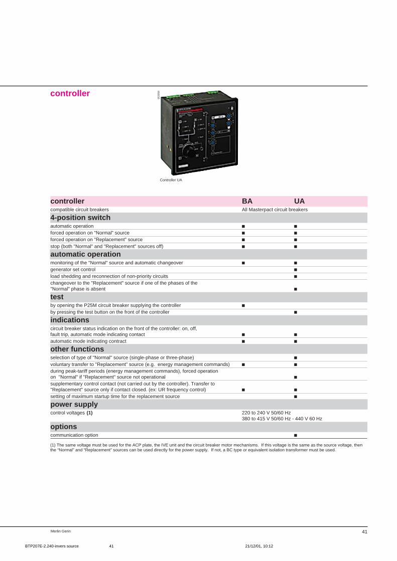
Merlin Gerin 41
Controller UA
controller
controller BA UAcompatible circuit breakers All Masterpact circuit breakers
4-position switchautomatic operation c cforced operation on "Normal" source c cforced operation on "Replacement" source c cstop (both "Normal" and "Replacement" sources off) c cautomatic operationmonitoring of the "Normal" source and automatic changeover c cgenerator set control cload shedding and reconnection of non-priority circuits cchangeover to the "Replacement" source if one of the phases of the"Normal" phase is absent ctestby opening the P25M circuit breaker supplying the controller cby pressing the test button on the front of the controller cindicationscircuit breaker status indication on the front of the controller: on, off,fault trip, automatic mode indicating contact c cautomatic mode indicating contract c cother functionsselection of type of "Normal" source (single-phase or three-phase) cvoluntary transfer to "Replacement" source (e.g. energy management commands) c cduring peak-tariff periods (energy management commands), forced operationon "Normal" if "Replacement" source not operational csupplementary control contact (not carried out by the controller). Transfer to"Replacement" source only if contact closed. (ex: UR frequency control) c csetting of maximum startup time for the replacement source cpower supplycontrol voltages (1) 220 to 240 V 50/60 Hz
380 to 415 V 50/60 Hz - 440 V 60 Hz
optionscommunication option c
(1) The same voltage must be used for the ACP plate, the IVE unit and the circuit breaker motor mechanisms. If this voltage is the same as the source voltage, thenthe “Normal” and “Replacement” sources can be used directly for the power supply. If not, a BC type or equivalent isolation transformer must be used.
0530
58
BTP207E-2.240-invers source 21/12/01, 10:1241
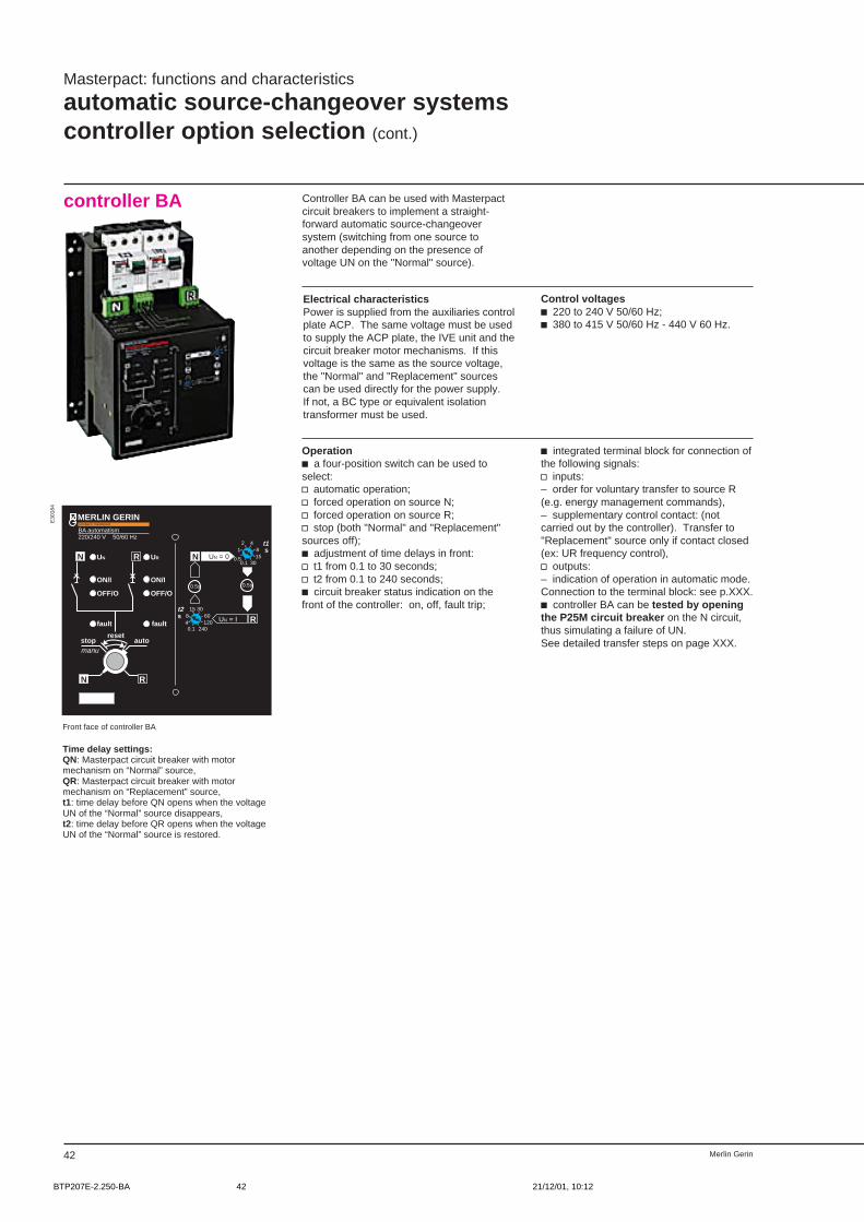
42 Merlin Gerin
Masterpact: functions and characteristics
automatic source-changeover systemscontroller option selection (cont.)
controller BA Controller BA can be used with Masterpactcircuit breakers to implement a straight-forward automatic source-changeoversystem (switching from one source toanother depending on the presence ofvoltage UN on the "Normal" source).
Control voltagesc 220 to 240 V 50/60 Hz;c 380 to 415 V 50/60 Hz - 440 V 60 Hz.
Electrical characteristicsPower is supplied from the auxiliaries controlplate ACP. The same voltage must be usedto supply the ACP plate, the IVE unit and thecircuit breaker motor mechanisms. If thisvoltage is the same as the source voltage,the "Normal" and "Replacement" sourcescan be used directly for the power supply.If not, a BC type or equivalent isolationtransformer must be used.
Operationc a four-position switch can be used toselect:v automatic operation;v forced operation on source N;v forced operation on source R;v stop (both "Normal" and "Replacement"sources off);c adjustment of time delays in front:v t1 from 0.1 to 30 seconds;v t2 from 0.1 to 240 seconds;c circuit breaker status indication on thefront of the controller: on, off, fault trip;
c integrated terminal block for connection ofthe following signals:v inputs:– order for voluntary transfer to source R(e.g. energy management commands),– supplementary control contact: (notcarried out by the controller). Transfer to"Replacement" source only if contact closed(ex: UR frequency control),v outputs:– indication of operation in automatic mode.Connection to the terminal block: see p.XXX.c controller BA can be tested by openingthe P25M circuit breaker on the N circuit,thus simulating a failure of UN.See detailed transfer steps on page XXX.
MERLIN GERINBA automatism220/240 V 50/60 Hz
N R
fault fault
UN UR
ON/I ON/I
OFF/O OFF/O
N
R
UN = 0
UN = I
4281
0.50.1
1530
3015608
40.1
120240
t1 s
t2s
compact / masterpact
0.5s 0.5s
N R
stopmanu
autoreset
E30
184
Front face of controller BA
Time delay settings:QN: Masterpact circuit breaker with motormechanism on “Normal” source,QR: Masterpact circuit breaker with motormechanism on “Replacement” source,t1: time delay before QN opens when the voltageUN of the “Normal” source disappears,t2: time delay before QR opens when the voltageUN of the “Normal” source is restored.
BTP207E-2.250-BA 21/12/01, 10:1242
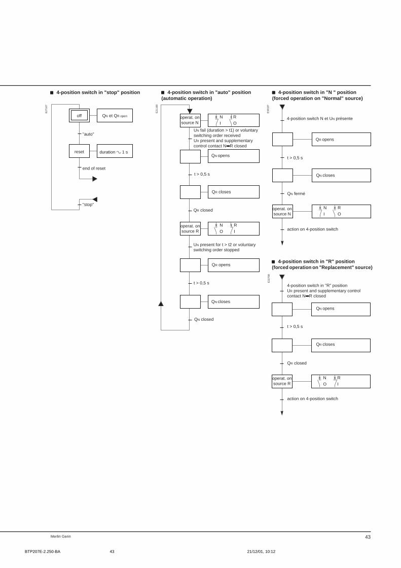
Merlin Gerin 43
RN
OI
RN
IO
RN
OI
RN
IO
E32
708
"auto"
operat. onsource N
UN fail (duration > t1) or voluntaryswitching order receivedUR present and supplementarycontrol contact NR closed
t > 0,5 s
QR closed
t > 0,5 s
QN closed
QN opens
QR closes
QR opens
QN closes
E21
108
E27
107
E30
187
4-position switch N et UN présente
QR opens
QN closes
operat. onsource N
QN fermé
4-position switch in "R" positionUR present and supplementary controlcontact NR closed
QN opens
QR closes
QR closed
t > 0,5 s
operat. onsource R
end of reset
"stop"
off QN et QR open
duration a 1 sreset
ccccc 4-position switch in "stop" position
UN present for t > t2 or voluntaryswitching order stopped
action on 4-position switch
t > 0,5 s
action on 4-position switch
ccccc 4-position switch in "R" position(forced operation on "Replacement" source)
operat. onsource R
ccccc 4-position switch in "auto" position(automatic operation)
ccccc 4-position switch in "N " position(forced operation on "Normal" source)
BTP207E-2.250-BA 21/12/01, 10:1243
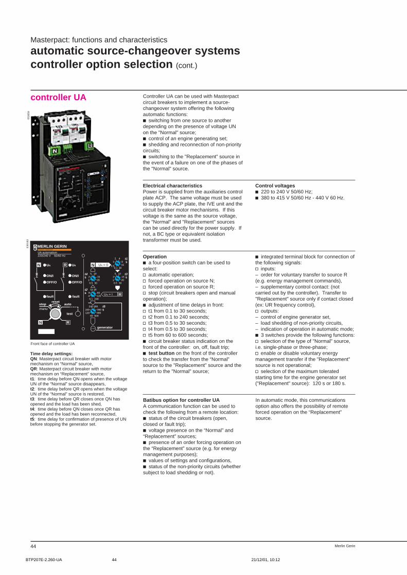
Merlin Gerin44
Masterpact: functions and characteristics
automatic source-changeover systemscontroller option selection (cont.)
controller UA Controller UA can be used with Masterpactcircuit breakers to implement a source-changeover system offering the followingautomatic functions:c switching from one source to anotherdepending on the presence of voltage UNon the "Normal" source;c control of an engine generating set;c shedding and reconnection of non-prioritycircuits;c switching to the "Replacement" source inthe event of a failure on one of the phases ofthe "Normal" source.
Electrical characteristicsPower is supplied from the auxiliaries controlplate ACP. The same voltage must be usedto supply the ACP plate, the IVE unit and thecircuit breaker motor mechanisms. If thisvoltage is the same as the source voltage,the "Normal" and "Replacement" sourcescan be used directly for the power supply. Ifnot, a BC type or equivalent isolationtransformer must be used.
Control voltagesc 220 to 240 V 50/60 Hz;c 380 to 415 V 50/60 Hz - 440 V 60 Hz.
Operationc a four-position switch can be used toselect:v automatic operation;v forced operation on source N;v forced operation on source R;v stop (circuit breakers open and manualoperation);c adjustment of time delays in front:v t1 from 0.1 to 30 seconds;v t2 from 0.1 to 240 seconds;v t3 from 0.5 to 30 seconds;v t4 from 0.5 to 30 seconds;v t5 from 60 to 600 seconds;c circuit breaker status indication on thefront of the controller: on, off, fault trip;c test button on the front of the controllerto check the transfer from the “Normal”source to the "Replacement" source and thereturn to the "Normal" source;
c integrated terminal block for connection ofthe following signals:v inputs:– order for voluntary transfer to source R(e.g. energy management commands),– supplementary control contact: (notcarried out by the controller). Transfer to"Replacement" source only if contact closed(ex: UR frequency control),v outputs:– control of engine generator set,– load shedding of non-priority circuits,– indication of operation in automatic mode;c 3 switches provide the following functions:v selection of the type of "Normal" source,i.e. single-phase or three-phase;v enable or disable voluntary energymanagement transfer if the "Replacement"source is not operational;v selection of the maximum toleratedstarting time for the engine generator set("Replacement" source): 120 s or 180 s.
Batibus option for controller UAA communication function can be used tocheck the following from a remote location:c status of the circuit breakers (open,closed or fault trip);c voltage presence on the “Normal” and“Replacement” sources;c presence of an order forcing operation onthe “Replacement” source (e.g. for energymanagement purposes);c values of settings and configurations,c status of the non-priority circuits (whethersubject to load shedding or not).
In automatic mode, this communicationsoption also offers the possibility of remoteforced operation on the “Replacement”source.
E30
183
MERLIN GERINUA automatism220/240 V 50/60 Hz
N R
N R
stopmanu
auto
test
reset
fault fault
UN UR
ON/I ON/I
OFF/O OFF/O
N
R
UN = 0
UN = I
STOP generator
4281
0.50.1
1530
105152
10.5
2030
105152
10.5
2030
3015608
40.1
120240
300240360160
12060
480600
t1 s
t3 s
t4s
t2s
t5s
compact / masterpact
Front face of controller UA
Time delay settings:QN: Masterpact circuit breaker with motormechanism on “Normal” source,QR: Masterpact circuit breaker with motormechanism on “Replacement” source,t1: time delay before QN opens when the voltageUN of the “Normal” source disappears,t2: time delay before QR opens when the voltageUN of the “Normal” source is restored,t3: time delay before QR closes once QN hasopened and the load has been shed,t4: time delay before QN closes once QR hasopened and the load has been reconnected,t5: time delay for confirmation of presence of UNbefore stopping the generator set.
0530
59
BTP207E-2.260-UA 21/12/01, 10:1244
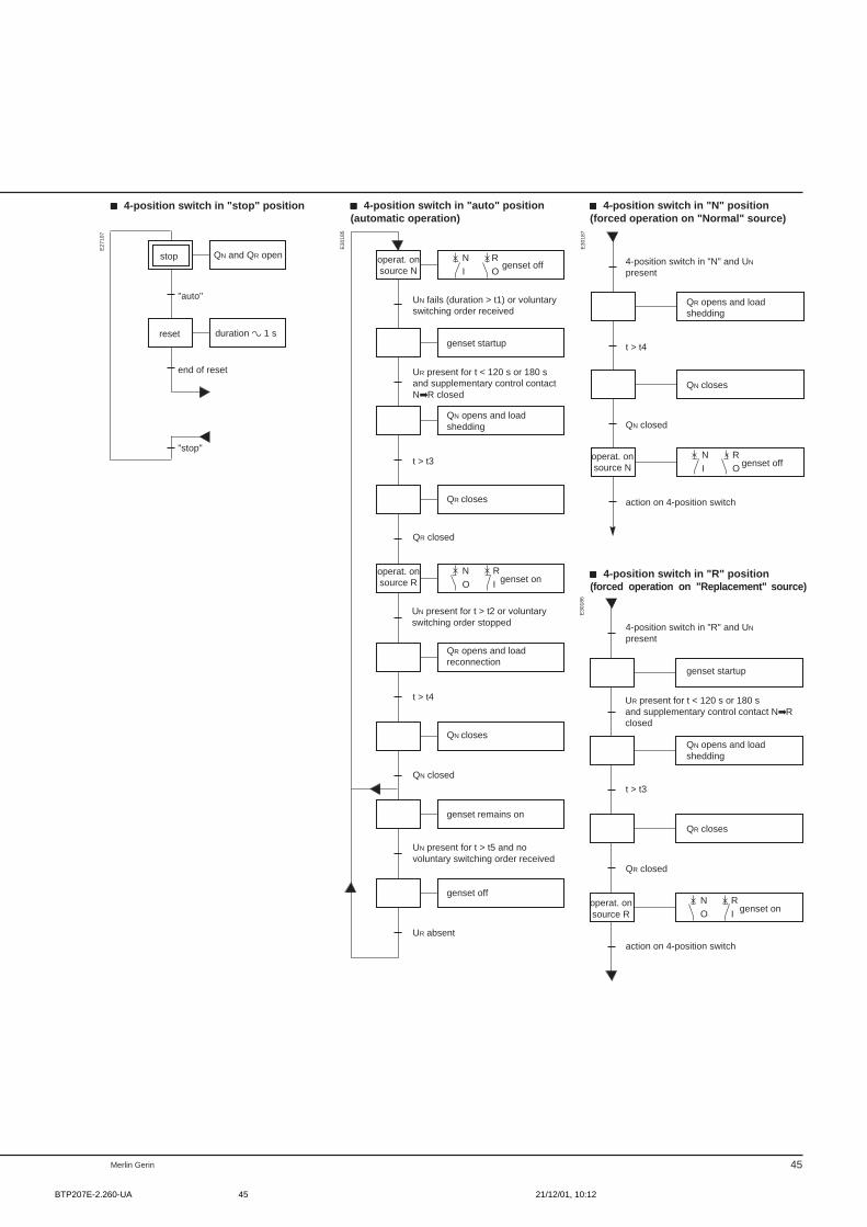
Merlin Gerin 45
RN
IO
RN
OI
RN
OI
RN
IO
operat. onsource N
genset off
genset startup
UN fails (duration > t1) or voluntaryswitching order received
t > t3
QR closes
QR closed
operat. onsource R genset on
t > t4
QN closes
QN closed
UN present for t > t5 and novoluntary switching order received
genset off
UR absent
4-position switch in "N" and UN
present
t > t4
QN closes
genset off
QN closed
4-position switch in "R" and UN
present
genset startup
UR present for t < 120 s or 180 sand supplementary control contact NRclosed
t > t3
QR closed
QR closes
E30
185
E30
187
E30
186
genset on
"auto"
E27
107
ccccc 4-position switch in "R" position(forced operation on "Replacement" source)
reset
end of reset
"stop"
stop
operat. onsource R
duration a 1 s
QN opens and loadshedding
UN present for t > t2 or voluntaryswitching order stopped
QR opens and loadreconnection
genset remains on
QR opens and loadshedding
operat. onsource N
action on 4-position switch
action on 4-position switch
QN opens and loadshedding
ccccc 4-position switch in "auto" position(automatic operation)
ccccc 4-position switch in "stop" position ccccc 4-position switch in "N" position(forced operation on "Normal" source)
QN and QR open
UR present for t < 120 s or 180 sand supplementary control contactNR closed
BTP207E-2.260-UA 21/12/01, 10:1245

Merlin Gerin40
BTP207E-3.001-sommaire 21/12/01, 10:1340
41
LV power air circuitbreakers andswitch-disconnectors
Masterpact
3/ installationand connection
page
installationgeneral 0safety clearance 0fixed circuit breakers M08 to M32 0drawout circuit breakers M08 to M32 0fixed circuit breaker M40 0drawout circuit breaker M40 0fixed circuit breaker M50 0drawout circuit breaker M50 0drawout circuit breaker M63 0manual source changeover systemsmanual and automatic sourcechangeover systems 0
connectionfixed and drawout circuit breakersM08N/M10N/M12N 0fixed and drawout circuit breakersM08H,L/M10H,L/M12H,L/M16N,H,L 0fixed and drawout circuit breakersM20N,H/M25N,H 0fixed and drawout circuit breakersM20L/M25L/M32H 0fixed and drawout circuit breaker M40 0fixed and drawout circuit breakerM08 to M16 0fixed and drawout circuit breakerM50 to M63 0wiring diagrams:c STR 18 M / 28 D / 38 S / 58 U 0c STR 28 D / 38 S / 58 U avec options 0c STR 68 U avec options m01 à m31 0c automatic source changeover 0c manual source changeover 0
BTP207E-3.001-sommaire 21/12/01, 10:1341
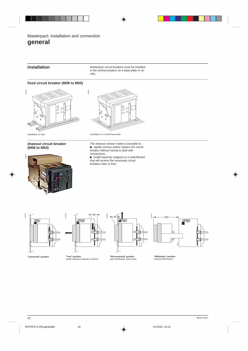
Merlin Gerin42
Installation on rails Installation on a metal base plate
E29
026
E28
811
0182
41E
3125
4
305E31
25726
E31
256
45E31
255
Masterpact: installation and connection
general
installation Masterpact circuit breakers must be installedin the vertical position on a base plate or onrails.
fixed circuit breaker (M08 to M50)
drawout circuit breaker(M08 to M63)
The drawout version makes it possible to:c rapidly remove and/or replace the circuitbreaker without having to deal withconnections;c install stand-by outgoers in a switchboardthat will receive the necessary circuitbreakers later in time
"Connected" position "Test" positionample clearance between contacts
"Disconnected" positioneasy withdrawal, short travel
"Withdrawn" positioncompact dimensions
BTP207E-3.200-généralité 21/12/01, 10:1442

43Merlin Gerin
Certain distances must be maintainedbetween a circuit breaker and otherelements such as panels, bars and othercircuit breakers. Taken together, thesedistances form the safety clearance for thecircuit breaker. The diagrams and the tablebelow indicate the required distances wheninstalling Masterpact circuit breakers.
These distances are the results of testscarried out in accordance with standardIEC 947-2 and are in part determined by theultimate breaking capacities.
Masterpact M08 to M50type of connection to insulated barrier to metal parts to live bars
A B C D (2) A B C D (2) A B C D (2)front connection without cover (1) 360 30 0 0 360 70 – 0 1085 420 – 0rear connection without cover 150 30 20 0 250 70 95 0 1085 420 495 0rear connection with cover 0 0 20 0 0 0 95 – 145 105 125 0
drawout circuit breaker
(1) Shield necessary.(2) D is the clearance required for connection ofauxiliaries.D = 0 for fixed circuit breakers (required clearanceincluded in the height of the connection plugs).D = 0 for drawout circuit breakers as well.
Masterpact: installation and connection
safety clearance
Note: For the fixed circuit breakers, a clearance of130 mm is required on top for removal of the arcchutes.
fixed circuit breaker
A
C100
D
E31
232
E31
233
B
A
B
A
B B
E31
230
A
C100
D
E31
229 C100
213
A
B
A
B
E31
231
Masterpact M08 to M63type of connection to insulated barrier to metal parts to live bars
A B C A B C A B Cfront connection without cover (1) 300 15 0 300 50 – 1000 400 –rear connection without cover 150 15 45 150 50 45 1000 400 445rear connection with cover 0 0 45 0 0 45 60 85 75
BTP207E-3.200-généralité 21/12/01, 10:1443

Merlin Gerin44
Rear horizontal connection Mixed connection.Upper terminals: front connection.Bottom terminals: vertical connection.
Rear vertical connectionFront connection
Masterpact: connection
general
Four types of connection are possible:c rear horizontal;c rear vertical;c front;c mixed.The terminals are sized to allow circuitbreaker connection with bars up to 20 mmthick (except for the M40, M50 and M63).
Conductor materialsThe terminals of Masterpact circuit breakerscan be used to connect bare copper, tinnedcopper or tinned aluminium conductorswithout any special surface treatment.
0168
08
0251
79
0168
06
0168
07
electrodynamic forces c the first bar spacers must be located atless than a certain distance from the circuitbreaker connection point;
c this maximum distance must berespected to withstand the electrodynamicforces that are applied between the barsduring a short-circuit.
Maximum distance between circuit breaker connection point and thefirst bar spacers for various short-circuit currentsIsc (kA) 30 50 65 80 100 150distance (mm) 350 300 250 150 150 150
BTP207E-3.210-généralité 21/12/01, 10:1644
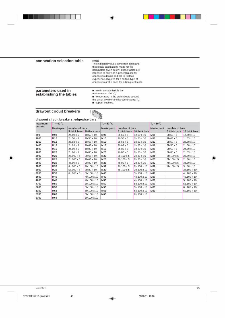
45Merlin Gerin
connection selection table Note:The indicated values come from tests andtheoretical calculations made for theparameters given below. These tables areintended to serve as a general guide forconnection design and not to replaceexperience acquired for a certain type ofconnection or the need for subsequent tests.
parameters used inestablishing the tables
c maximum admissible bartemperature: 100 °C;c temperature in the switchboard aroundthe circuit breaker and its connections: Ta;c copper busbars.
drawout circuit breakers
E31
258
drawout circuit breakers, edgewise barsmaximum T a = 40 °C Ta = 50 °C Ta = 60°Ccurrent
Masterpact number of bars Masterpact number of bars Masterpact number of bars5 thick bars 10 thick bars 5 thick bars 10 thick bars 5 thick bars 10 thick bars
800 M08 2b.50 x 5 1b.50 x 10 M08 2b.50 x 5 1b.50 x 10 M08 2b.50 x 5 1b.50 x 101000 M10 2b.50 x 5 1b.50 x 10 M10 2b.50 x 5 1b.50 x 10 M10 2b.63 x 5 1b.63 x 101250 M12 2b.63 x 5 1b.63 x 10 M12 2b.63 x 5 1b.63 x 10 M12 3b.50 x 5 2b.50 x 101400 M16 2b.63 x 5 1b.63 x 10 M16 2b.63 x 5 1b.63 x 10 M16 3b.50 x 5 2b.50 x 101600 M16 2b.80 x 5 1b.80 x 10 M16 2b.80 x 5 1b.80 x 10 M20 3b.63 x 5 2b.50 x 101800 M20 2b.80 x 5 1b.80 x 10 M20 2b.80 x 5 2b.50 x 10 M20 3b.80 x 5 2b.63 x 102000 M20 2b.100 x 5 2b.63 x 10 M20 2b.100 x 5 2b.63 x 10 M25 3b.100 x 5 2b.80 x 102200 M25 2b.100 x 5 2b.63 x 10 M25 2b.100 x 5 2b.63 x 10 M25 3b.100 x 5 2b.80 x 102500 M25 4b.80 x 5 2b.80 x 10 M25 4b.80 x 5 2b.80 x 10 M32 4b.100 x 5 3b.80 x 102800 M32 4b.100 x 5 2b.100 x 10 M32 4b.100 x 5 2b.100 x 10 M32 4b.100 x 5 3b.80 x 103000 M32 5b.100 x 5 3b.80 x 10 M32 6b.100 x 5 3b.100 x 10 M40 3b.100 x 103200 M32 6b.100 x 5 3b.100 x 10 M40 3b.100 x 10 M40 4b.100 x 103600 M40 4b.100 x 10 M40 4b.100 x 10 M50 4b.100 x 104000 M40 4b.100 x 10 M50 4b.100 x 10 M50 5b.100 x 104700 M50 5b.100 x 10 M50 5b.100 x 10 M50 5b.100 x 105000 M50 5b.100 x 10 M50 5b.100 x 10 M63 6b.100 x 105100 M63 5b.100 x 10 M63 6b.100 x 10 M63 6b.100 x 105700 M63 6b.100 x 10 M63 6b.100 x 106300 M63 6b.100 x 10
BTP207E-3.210-généralité 21/12/01, 10:1645

Merlin Gerin48
Masterpact: installation
fixed circuit breakers M08 to M32
dimensions3 or 4 poles
(*) Datum
90 130
311
45
6830 mini60 maxi
290
150
(*)
necessary space for removing the arc chutes(with or without arc chute cover)
1111 515
11 11
(*)
493
553
378
438
400
422 (3p)
537 (4p)
on rails
mountingon a base plate
(*) Datum
150
30 mini60 maxi
150
30 mini60 maxi
mounting detail
3 poles 4 polesA 150 150B 400 515
cut-outscut-outs de porte holes for escutcheon
Ø14
2 Ø11 x 6Ø11
B
A
E30
742 E
3074
8
E30
749
E30
765
E30
766
E30
775
152,5
148,5
6971,5
17,518018011 Ø5
14,5
325
(*)
37,580 mini
270
27
(*)
80 mini
E30
763
E30
764
BTP207E-3.230-M08…32 21/12/01, 10:1748
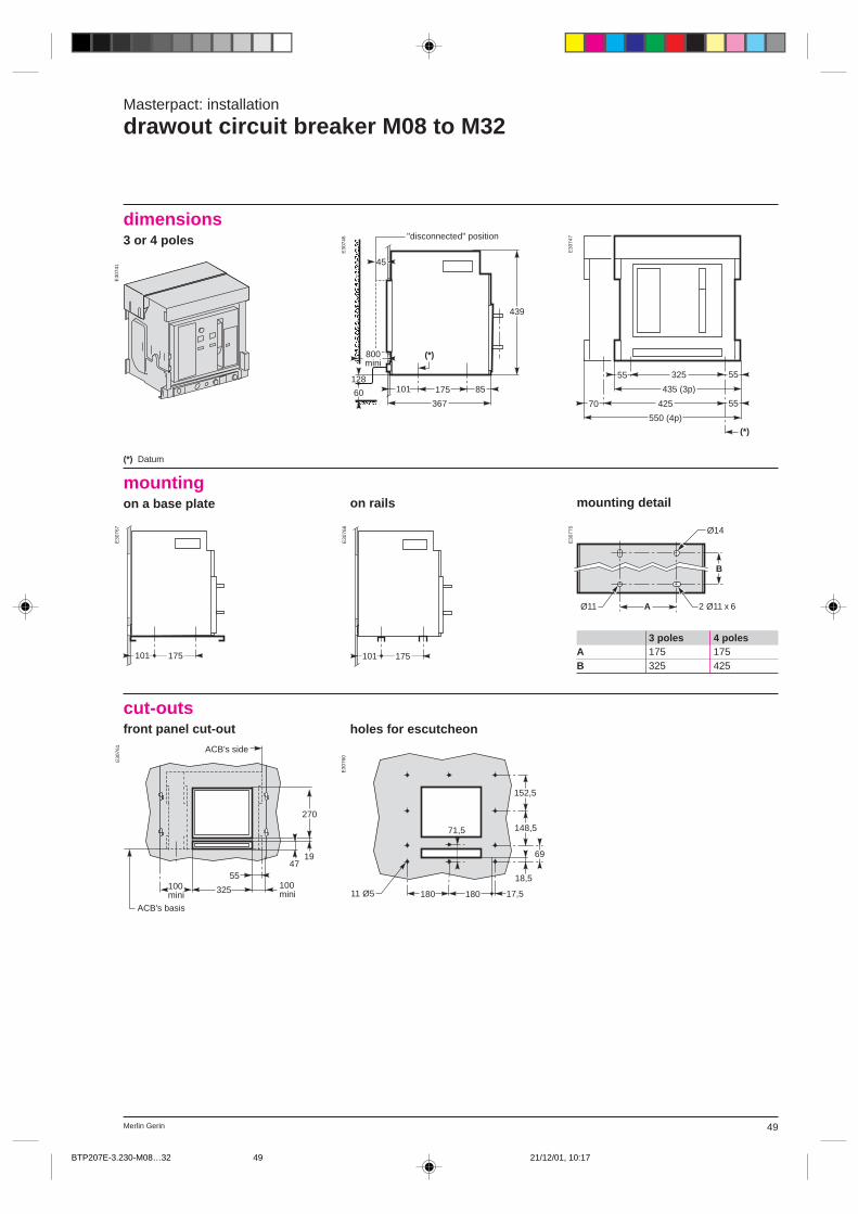
49Merlin Gerin
Masterpact: installation
drawout circuit breaker M08 to M32
dimensions3 or 4 poles
(*) Datum
mounting detailon railsmountingon a base plate
3 poles 4 polesA 175 175B 325 425
cut-outsfront panel cut-out
Ø14
2 Ø11 x 6Ø11
B
A
aaaaaaa (*)45
10160367
175 85
439
128
800mini
"disconnected" position
(*)
70 55425
5532555
435 (3p)
550 (4p)
175101 175101
E30
747
E30
746
E30
741
E30
768
E30
767
E30
775
holes for escutcheon
325
55100 mini
100 mini
270
4719
ACB's side
ACB's basis
152,5
148,5
69
71,5
18,5
17,518018011 Ø5
E30
760
E30
761
BTP207E-3.230-M08…32 21/12/01, 10:1749
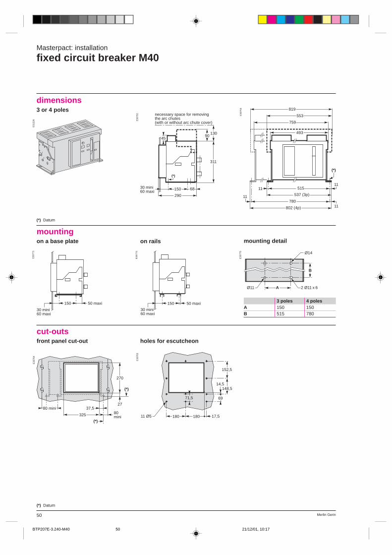
Merlin Gerin50
Masterpact: installation
fixed circuit breaker M40
(*) Datum
759
819
553
493
(*)
1111 515
537 (3p)
78011
11
802 (4p)
dimensions3 or 4 poles
on rails
mountingon a base plate mounting detail
150
30 mini60 maxi
50 maxi 150
30 mini60 maxi
50 maxi
Ø14
2 Ø11 x 6Ø11
B
A
3 poles 4 polesA 150 150B 515 780
cut-outsfront panel cut-out
(*) Datum
90130
311
45
6830 mini60 maxi
290
150
(*)
necessary space for removing the arc chutes(with or without arc chute cover)
E31
226 E30
752
E30
753
E30
771
E30
772
E30
775
holes for escutcheon
325
(*)
37,580 mini
270
27
(*)
80 mini
152,5
148,5
6971,5
17,518018011 Ø5
14,5
E30
764
E30
763
BTP207E-3.240-M40 21/12/01, 10:1750

51Merlin Gerin
Masterpact: installation
drawout circuit breaker M40
dimensions3 or 4 polesaaaaaaa (*)101
60
367
175 85
439
128
484
45
800mini
(1)
"disconnected" position
70 55425
60 350 55350
(*)
550 (3p)
815 (4p)
(*) Datum(1) 4-pole version only.
on rails
mountingon a base plate mounting detail
175101
(1)
175101
(1) 175 2 Ø11 x 6 (3p)6 Ø11 x 22 (4p)
350
350
150
40 40 30
(1) 4-pole version only.
cut-outsfront panel cut-out
(1) 4-pole version only.
E30
743
E30
750
E30
751
E30
773
E30
774
E30
777
holes for escutcheon
325
55100 mini
27047
19
45 (1)
ACB's side
ACB's basis
152,5
148,5
69
71,5
18,5
17,518018011 Ø5
E30
760
E30
762
BTP207E-3.240-M40 21/12/01, 10:1751

Merlin Gerin50
Masterpact: installation
fixed circuit breaker M40
(*) Datum
759
819
553
493
(*)
1111 515
537 (3p)
78011
11
802 (4p)
dimensions3 or 4 poles
on rails
mountingon a base plate mounting detail
150
30 mini60 maxi
50 maxi 150
30 mini60 maxi
50 maxi
Ø14
2 Ø11 x 6Ø11
B
A
3 poles 4 polesA 150 150B 515 780
cut-outsfront panel cut-out
(*) Datum
90130
311
45
6830 mini60 maxi
290
150
(*)
necessary space for removing the arc chutes(with or without arc chute cover)
E31
226 E30
752
E30
753
E30
771
E30
772
E30
775
holes for escutcheon
325
(*)
37,580 mini
270
27
(*)
80 mini
152,5
148,5
6971,5
17,518018011 Ø5
14,5
E30
764
E30
763
BTP207E-3.240-M40 21/12/01, 10:1750
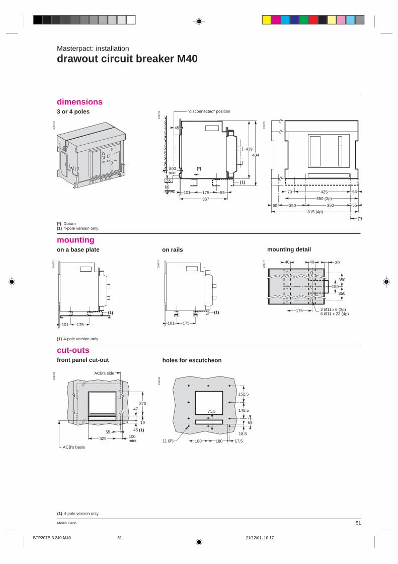
51Merlin Gerin
Masterpact: installation
drawout circuit breaker M40
dimensions3 or 4 polesaaaaaaa (*)101
60
367
175 85
439
128
484
45
800mini
(1)
"disconnected" position
70 55425
60 350 55350
(*)
550 (3p)
815 (4p)
(*) Datum(1) 4-pole version only.
on rails
mountingon a base plate mounting detail
175101
(1)
175101
(1) 175 2 Ø11 x 6 (3p)6 Ø11 x 22 (4p)
350
350
150
40 40 30
(1) 4-pole version only.
cut-outsfront panel cut-out
(1) 4-pole version only.
E30
743
E30
750
E30
751
E30
773
E30
774
E30
777
holes for escutcheon
325
55100 mini
27047
19
45 (1)
ACB's side
ACB's basis
152,5
148,5
69
71,5
18,5
17,518018011 Ø5
E30
760
E30
762
BTP207E-3.240-M40 21/12/01, 10:1751
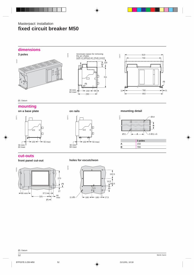
Merlin Gerin52
Masterpact: installation
fixed circuit breaker M50
dimensions3 poles
(*) Datum
90130
311
45
6830 mini60 maxi
290
150
(*)
necessary space for removing the arc chutes(with or without arc chute cover)
(*)
1111 780
802
759
819
(*) Datum
on rails
mountingon a base plate mounting detail
150
30 mini60 maxi
50 maxi 150
30 mini60 maxi
50 maxi
Ø14
2 Ø11 x 6Ø11
B
A
3 polesA 150B 780
cut-outsfront panel cut-out
E31
227
E30
756
E30
757
E30
775
E30
772
E30
771
holes for escutcheon
152,5
148,5
6971,5
17,518018011 Ø5
14,5
325
(*)
37,580 mini
270
27
(*)
80 mini
E30
764
E30
763
BTP207E-3.250-M50 21/12/01, 10:1852
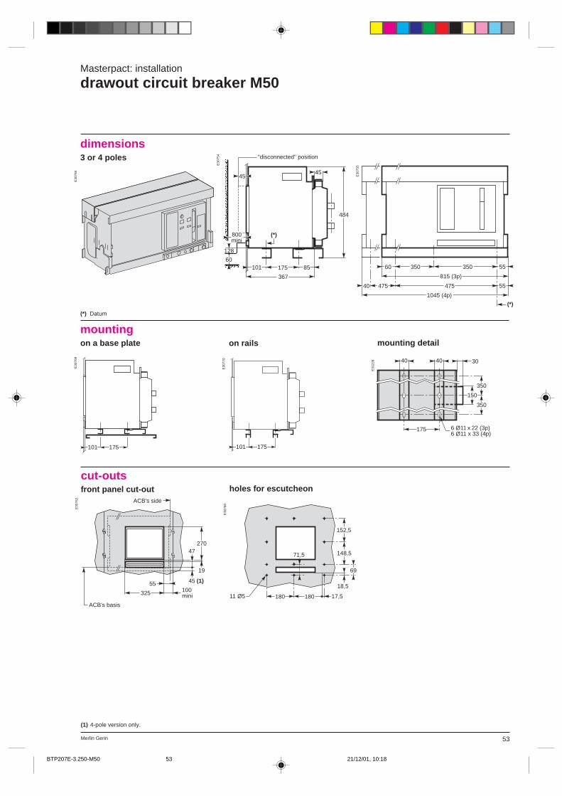
53Merlin Gerin
Masterpact: installation
drawout circuit breaker M50
dimensions3 or 4 poles
(*)
45
10160
367
175 85
128
484aaaaaaa 45
800mini
"disconnected" position
60 350 55350
(*)
815 (3p)
5547547540
1045 (4p)
(1) 4-pole version only.
(*) Datum
on rails
mountingon a base plate mounting detail
175101 175101
175 6 Ø11 x 22 (3p)6 Ø11 x 33 (4p)
350
350
150
40 40 30
cut-outsfront panel cut-out
E30
744
E30
754
E30
755
E31
228
E30
770
E30
769
holes for escutcheon
325
55100 mini
27047
19
45 (1)
ACB's side
ACB's basis
152,5
148,5
69
71,5
18,5
17,518018011 Ø5
E30
762
E30
760
BTP207E-3.250-M50 21/12/01, 10:1853
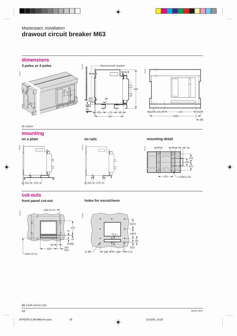
Merlin Gerin54
(1) 4-pole version only.
Masterpact: installation
drawout circuit breaker M63
dimensions3 poles or 4 poles
40 475 55475
(*)1045
(*) Datum
on rails
mountingon a plate mounting detail
175101 175101
cut-outsfront panel cut-out holes for escutcheon
152,5
148,5
69
71,5
18,5
17,518018011 Ø5
175 6 Ø11 x 33
475
475
40 40 30
150
E30
745
E30
758
E30
759
E30
778
E30
769
E30
770
E30
762
E30
760
(*)
45
10160
367
175 85
128
484aaaaaaa800mini
45
"disconnected" position
325
55100 mini
27047
19
45 (1)
side of c.b.
base of c.b.
BTP207E-3.260-M63+inv sour 21/12/01, 10:1854
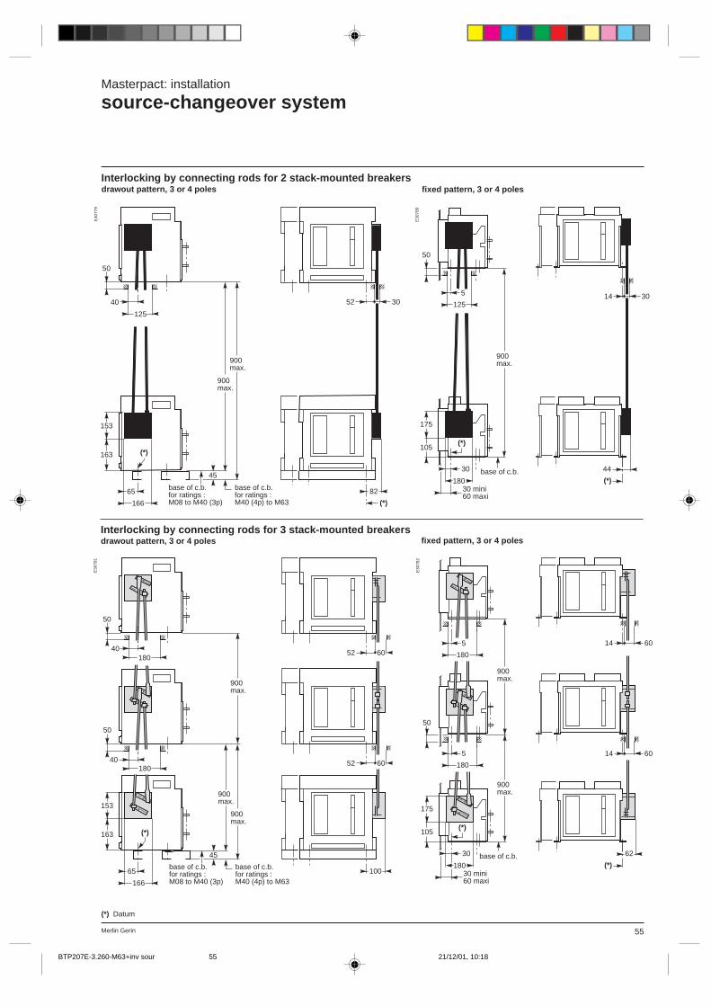
55Merlin Gerin
Masterpact: installation
source-changeover system
Interlocking by connecting rods for 2 stack-mounted breakersdrawout pattern, 3 or 4 poles
(*) Datum
fixed pattern, 3 or 4 poles
fixed pattern, 3 or 4 polesInterlocking by connecting rods for 3 stack-mounted breakersdrawout pattern, 3 or 4 poles
E30
779
E30
780
E30
782
E30
781
base of c.b.for ratings :M08 to M40 (3p)
base of c.b.for ratings :M40 (4p) to M63 (*)
3052
82
40
125
50
153
163 (*)
65
166
45
900max.
900max.
base of c.b.
5
125
50
175
105(*)
30
18030 mini60 maxi
900max.
3014
(*)
44
base of c.b.for ratings :M08 to M40 (3p)
base of c.b. for ratings :M40 (4p) to M63
6052
100
40180
50
153
163 (*)
65
166
45
900max.
900max.
40180
50
900max.
6052
base of c.b.
5
180
175
105(*)
30
18030 mini60 maxi
900max.
6014
(*)
62
50
5
180
900max.
6014
BTP207E-3.260-M63+inv sour 21/12/01, 10:1855
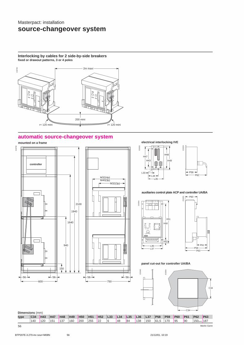
Merlin Gerin56
Masterpact: installation
source-changeover system
Interlocking by cables for 2 side-by-side breakersfixed or drawout patterns, 3 or 4 poles
2m maxi
200 mini
r= 120 mini r= 120 mini
E30
783
E30
784
Dimensions (mm)type C34 H43 H47 H48 H49 H50 H51 H52 L33 L34 L35 L36 L37 P58 P59 P60 P61 P62 P63
140 120 151 137 160 200 255 22 6 48 84 138 150 61,5 170 95 90 150(min) 187
automatic source-changeover systemmounted on a frame
600
56 56
150
940
1640
1940
2100
750
56 56
M32(3p)
M32(4p)M40(3p)
controller
panel cut-out for controller UA/BA
C34
C34
E33
364
E33
363
E33
355
L37L36
H50
H51
H52
E33
354
auxiliaries control plate ACP and controller UA/BA
E33
352
E33
353
N R
1
2
3
4
5
6
7
8
9
10
11
12
13
14
15
16
H43
H47
L35L34
L33
H49
H48
electrical interlocking IVE
P58P62
P59
P60
P61
P63
BTP207E-3.270-inv sour+M08N 21/12/01, 10:1956
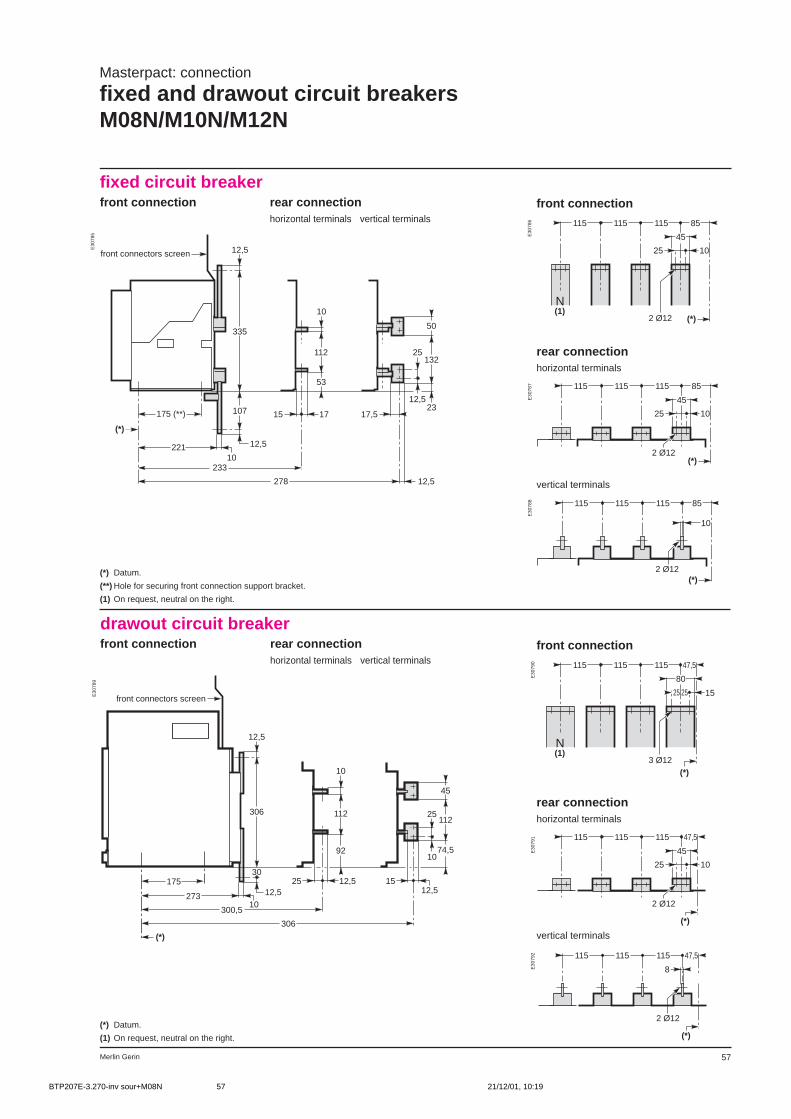
Merlin Gerin 57
front connection
rear connectionhorizontal terminals
1025
45
85115115115
(*)2 Ø12
vertical terminals
10
85115115115
(*)2 Ø12
Masterpact: connection
fixed and drawout circuit breakersM08N/M10N/M12N
front connection
rear connectionhorizontal terminals
1025
45
47,5115115115
(*)
2 Ø12
vertical terminals
8
47,5115115115
(*)
2 Ø12
1025
45
85115115115
(*)
N(1)
2 Ø12
1525
80
47,5115115115
(*)
N(1)
3 Ø12
25
(*) Datum.
(**) Hole for securing front connection support bracket.
(1) On request, neutral on the right.
(*) Datum.
(1) On request, neutral on the right.
E30
785 E30
786
E30
787
E30
788
E30
790
E30
791
E30
792
E30
789
drawout circuit breakerfront connection rear connection
horizontal terminals vertical terminals
fixed circuit breakerfront connection rear connection
horizontal terminals vertical terminals
175 (**)
221 12,5
10
107
335
12,5
233
15 17
53
112
10
278 12,5
17,5
12,5
25
23
132
50
(*)
front connectors screen
306
12,5
30
12,510
273
25
300,5
12,5
306
1512,5
112
10
9210
25112
74,5
45
175
(*)
front connectors screen
BTP207E-3.270-inv sour+M08N 21/12/01, 10:1957
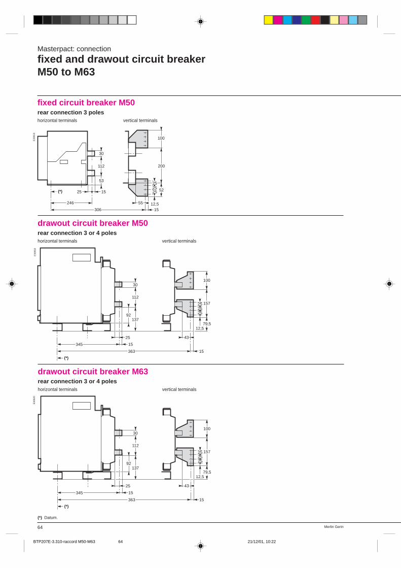
Merlin Gerin64
fixed circuit breaker M50rear connection 3 poleshorizontal terminals vertical terminals
Masterpact: connection
fixed and drawout circuit breakerM50 to M63
E30
819
246
112
15(*)
53
30
25
306
55
1512,5
252525
52
100
200
drawout circuit breaker M50rear connection 3 or 4 poleshorizontal terminals vertical terminals
E30
810
92
15
25
345
(*)
363
137
112
30
15
12,5
252525
79,5
157
100
43
drawout circuit breaker M63rear connection 3 or 4 poleshorizontal terminals vertical terminals
92
15
25
345
(*)
363
137
112
30
15
12,5
252525
79,5
157
100
43
(*) Datum.
E30
820
BTP207E-3.310-raccord M50-M63 21/12/01, 10:2264
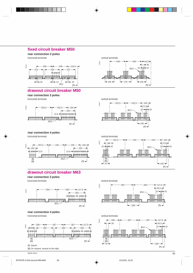
65Merlin Gerin
fixed circuit breaker M50rear connection 3 poleshorizontal terminals vertical terminals
E30
826 E
3082
7
(*) Datum.
(1) On request, neutral on the right.
10
(*)
Ø12 10
35
142,5
145175
248248
145
(*)Ø12
252525
226 213
142,5
20
248
1320
248
213
drawout circuit breaker M50rear connection 3 poleshorizontal terminals vertical terminals
E30
828 E
3082
9
10
(*)
Ø12 10
72,5
100252,5252,5
145
25 25 2525 25 25 45
220
100
(*)
252,5252,5
Ø12
12,5
rear connection 4 poleshorizontal terminals vertical terminals
E30
830 E
3083
1
25 25 2525 25 25 45
220
100
(*)
245245
Ø12
12,5
297,5
100
25 25 25 12,5
N(1)
10
(*)
Ø12
N(1)
10
72,5
100245245297,5
35
14570
10 10
drawout circuit breaker M63rear connection 3 poleshorizontal terminals vertical terminals
E30
823
10
(*)
Ø12 10
92,5
117,5350350
185
25 25 2525 25 25 85
260
117,5
(*)
350350
Ø12
10
(*)
Ø12
N(1)
10
92,5
117,5287287206
35
18570
25 25 2525 25 25 85
260
117,5
(*)
260
287287
260100
25 25 25
206
Ø12N(1)
E30
824
E30
825
E30
822
rear connection 4 poleshorizontal terminals vertical terminals
BTP207E-3.310-raccord M50-M63 21/12/01, 10:2265
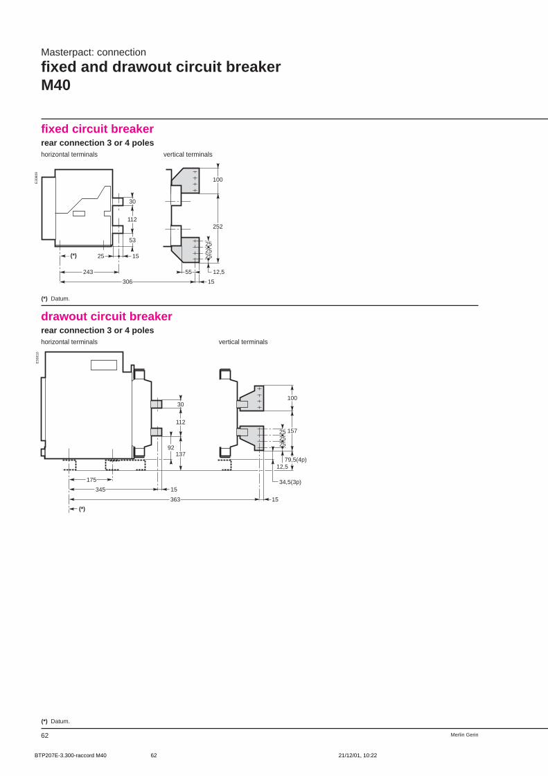
Merlin Gerin62
fixed circuit breakerrear connection 3 or 4 poleshorizontal terminals vertical terminals
Masterpact: connection
fixed and drawout circuit breakerM40
243
112
15(*)
53
30
25
306
55
15
12,5
252525
252
100
E30
809
(*) Datum.
drawout circuit breakerrear connection 3 or 4 poleshorizontal terminals vertical terminals
92
15
175
345
(*)
363
137
112
30
15
34,5(3p)
12,5
252525
79,5(4p)
157
100
E30
810
(*) Datum.
BTP207E-3.300-raccord M40 21/12/01, 10:2262
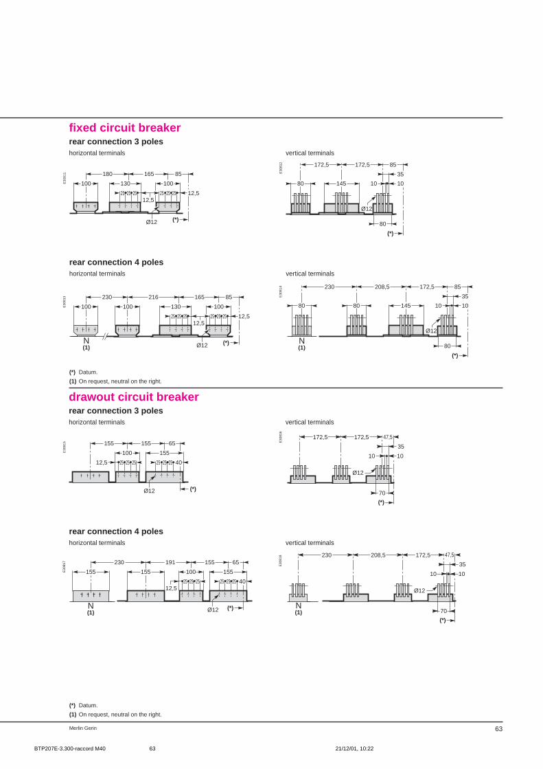
63Merlin Gerin
N(1)
(*)Ø12
65155
100 155
4025 25 2525252512,5
191
155155
230
fixed circuit breakerrear connection 3 poleshorizontal terminals vertical terminals
10
(*)
Ø12
10
35
85
80
145
172,5172,5
80100
12,525 25 2512,5
25 25 25
130
165
(*)
85180
Ø12
100
rear connection 4 poleshorizontal terminals vertical terminals
10
(*)
Ø12
10
35
85
80
145
172,5208,5
8080
230
N(1)
100
12,525 25 2512,5
25 25 25
130
165
(*)
85216
Ø12
100100
230
N(1)
E30
813 E
3081
4
E30
811 E
3081
2
(*) Datum.
(1) On request, neutral on the right.
drawout circuit breakerrear connection 3 poleshorizontal terminals vertical terminals
rear connection 4 poleshorizontal terminals vertical terminals
E30
818
E30
815 E
3081
6
(*) Datum.
(1) On request, neutral on the right.
4025 25 2525252512,5
100 155
65
(*)
155155
Ø12
10 10
35
47,5
(*)
Ø12
172,5172,5
70
10 10
35
47,5
(*)
Ø12
172,5208,5
70
230
N(1)
E30
817
BTP207E-3.300-raccord M40 21/12/01, 10:2263
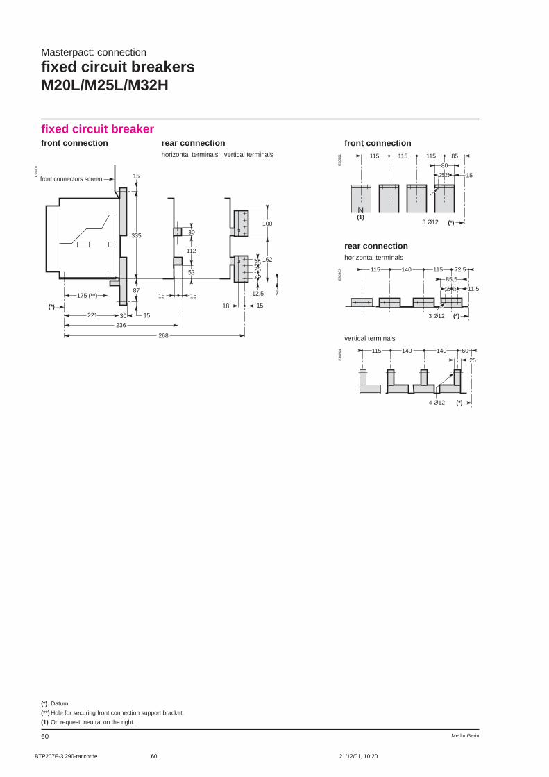
Merlin Gerin60
fixed circuit breakerfront connection rear connection
horizontal terminals vertical terminals
front connection
rear connectionhorizontal terminals
vertical terminals
Masterpact: connection
fixed circuit breakersM20L/M25L/M32H
11,5
85,5
72,5115140115
(*)3 Ø12
2525
1525
80
85115115115
(*)
N(1)
3 Ø12
25
60140140115
(*)4 Ø12
25
E30
802 E
3090
1E
3080
3E
3080
4
175 (**)
221 1530
87
335
15
236
18 15
53
112
30
268
18
12,5
25
7
162
100
(*)
25
15
25
front connectors screen
(*) Datum.
(**) Hole for securing front connection support bracket.
(1) On request, neutral on the right.
BTP207E-3.290-raccorde 21/12/01, 10:2060

61Merlin Gerin
drawout circuit breakerfront connection rear connection
horizontal terminals vertical terminals
front connection
rear connectionhorizontal terminals
vertical terminals
12,525
37,5125125115
(*)
N(1)
4 Ø12
2525
100
363
15
37
1530
329
344 15
92
112
30
(*)
344 15
25
12,5
2525
34,5
157
100
front connectors sceen
10152,5152,5115
(*)4 Ø12
25
12,525
37,5125125115
(*)4 Ø12
2525
100
E30
806
E30
807
E30
808
E30
805
Masterpact: connection
drawout circuit breakersM20L/M25L/M32H
(*) Datum.
(1) On request, neutral on the right.
BTP207E-3.290-raccorde 21/12/01, 10:2061
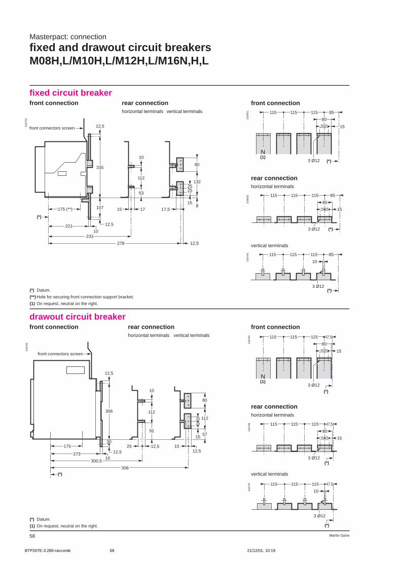
Merlin Gerin58
10
85115115115
(*)3 Ø12
175 (**)
221 12,5
10
107
335
12,5
233
15 17
53
112
10
278 12,5
17,5
158
132
80
(*)
2525
front connectors screen
fixed circuit breakerfront connection rear connection
horizontal terminals vertical terminals
front connection
rear connectionhorizontal terminals
vertical terminals
Masterpact: connection
fixed and drawout circuit breakersM08H,L/M10H,L/M12H,L/M16N,H,L
drawout circuit breakerfront connection rear connection
horizontal terminals vertical terminals
front connection
306
12,5
30
12,510
273
25
300,5
12,5
306
1512,5
112
10
9215
25 112
57
80
175
25
(*)
front connectors screen
rear connectionhorizontal terminals
vertical terminals
10
47,5115115115
(*)
3 Ø12
1525
80
47,5115115115
(*)
N(1)
3 Ø12
25
(*) Datum.
(**) Hole for securing front connection support bracket.
(1) On request, neutral on the right.
(*) Datum.
(1) On request, neutral on the right.
15
80
85115115115
(*)3 Ø12
2525
1525
80
85115115115
(*)
N(1)
3 Ø12
25
15
80
47,5115115115
(*)3 Ø12
2525
E30
793 E
3090
1E
3083
2E
3079
4E
3079
0E
3079
6E
3079
7
E30
795
BTP207E-3.280-raccorde 21/12/01, 10:1958
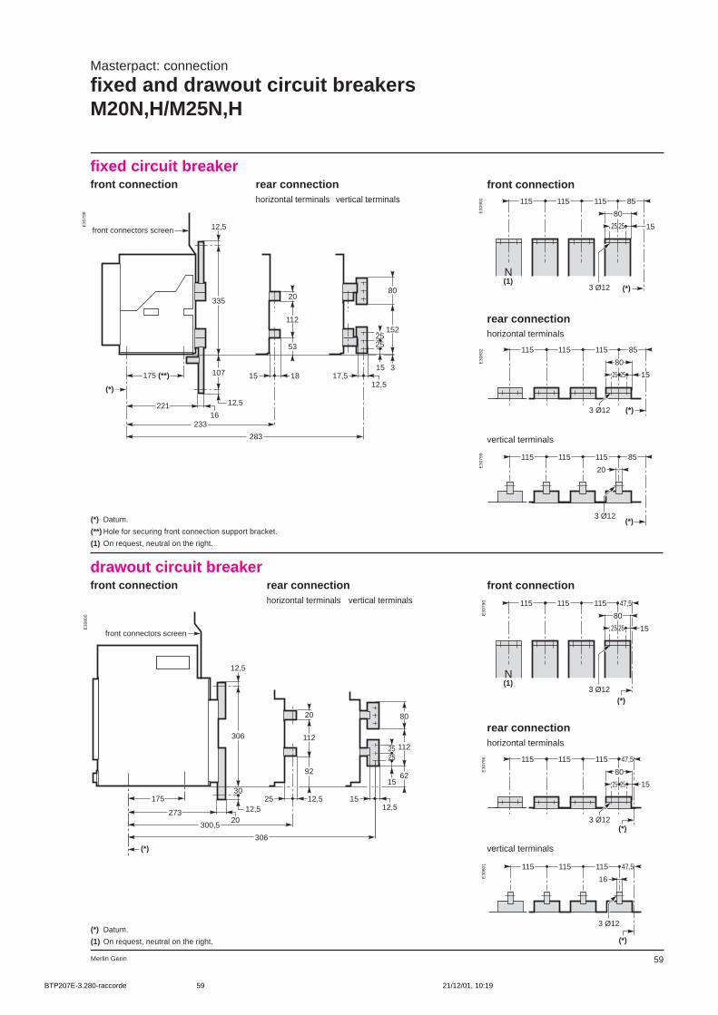
59Merlin Gerin
fixed circuit breakerfront connection rear connection
horizontal terminals vertical terminals
front connection
rear connectionhorizontal terminals
vertical terminals
Masterpact: connection
fixed and drawout circuit breakersM20N,H/M25N,H
drawout circuit breakerfront connection rear connection
horizontal terminals vertical terminals
front connection
306
12,5
30
12,520
273
25
300,5
12,5
306
1512,5
112
20
9215
25 112
62
80
175
25
(*)
front connectors screen
rear connectionhorizontal terminals
vertical terminals
1525
80
47,5115115115
(*)
N(1)
3 Ø12
25
(*) Datum.
(**) Hole for securing front connection support bracket.
(1) On request, neutral on the right.
(*) Datum.
(1) On request, neutral on the right.
20
85115115115
(*)3 Ø12
15
80
85115115115
(*)3 Ø12
2525
1525
80
85115115115
(*)
N(1)
3 Ø12
25
15
80
47,5115115115
(*)3 Ø12
2525
16
47,5115115115
(*)
3 Ø12
E30
798 E
3090
1E
3083
2E
3079
9E
3079
0E
3079
6E
3080
1
E30
800
175 (**)
221 12,5
16
107
335
12,5
233
15 18
53
112
20
283
17,515
25
3
152
80
(*)
25
12,5
front connectors screen
BTP207E-3.280-raccorde 21/12/01, 10:1959
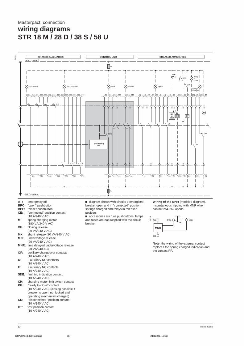
Merlin Gerin66
Masterpact: connection
wiring diagramsSTR 18 M / 28 D / 38 S / 58 U
12 14
SDE
Fu
81
22 24 32 34
BPO
11 21 31
CN 1 - CN +
CN2 - CN –
Fu
314 312 324 322
311 321
352 354 362 364
CD
351 361
334 332 344 342
CE
331 341
82 84
211
212
221
222
O
231
234
O
241
244 42 44 D4 C12
41 D1
OF
C11
MX
C2
C1
MX
A4
A1
XF
252 254
251
PF
262 B4
B1
CH
AT
BPF
M
F F
372 374
CT
371
disconnected fault openconnected
MNor
MNR
or
readytoclose
springscharged
closed
CHASSIS AUXILIARIES CONTROL UNIT BREAKER AUXILIARIES
processingunit
MNR
D4
D1
254 262
Note: the wiring of the external contactreplaces the spring charged indication andthe contact PF.
AT: emergency offBPO: "open" pushbuttonBPF: "close" pushbuttonCE: "connected" position contact
(10 A/240 V AC)M: spring charging motor
(180 VA/240 V AC)XF: closing release
(20 VA/240 V AC)MX: shunt release (20 VA/240 V AC)MN: undervoltage release
(20 VA/240 V AC)MNR: time delayed undervoltage release
(20 VA/240 AC)OF: auxiliary changeover contacts
(10 A/240 V AC)O: 2 auxiliary NO contacts
(10 A/240 V AC)F: 2 auxiliary NC contacts
(10 A/240 V AC)SDE: fault trip indication contact
(10 A/240 V AC)CH: charging motor limit switch contactPF: "ready to close" contact
(10 A/240 V AC) (closing possible ifbreaker is open, not locked andoperating mechanism charged)
CD: "disconnected" position contact(10 A/240 V AC)
CT: test posiiton contact(10 A/240 V AC)
c diagram shown with circuits deenergised,breaker open and in "connected" position,springs charged and relays in releasedposition;c accessories such as pushbuttons, lampsand fuses are not supplied with the circuitbreaker.
Wiring of the MNR (modified diagram).Instantaneous tripping with MNR whencontact 254-262 opens.
E30
721
E30
718
BTP207E-3.320-raccord 21/12/01, 10:2366
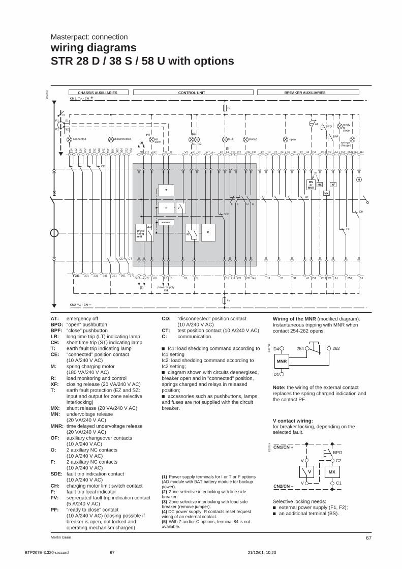
67Merlin Gerin
T1T2 12 14
SDE
Fu
81
22 24 32 34
BPO
11 21 31
CN 1 - CN +
CN2 - CN –
Fu
314
311
82 84
211
212
221
222
O
231
234
O
241
244 42 44 D4 C12
41 D1
OF
C11
MX
C2
C1
MX
A4
A1
XF
252 254
251
PF
262 B4
B1
CH
AT
BPF
M
F F
311 321 331 341 351 361
312
324
322
334
332
344
342
352
354
362
364
N
S1
S2
CE
CD
371
372
374
CT
C
V2
V1
V
Z21 Z22 F1F2
(3)
R
(2)
P1
P2
(5)Z11
LR1
Z12 LR2 R1 R2
(4)
Ic1 Ic2
e + e –
(4)
ALR
T
F
C
disconnected fault openconnected
MNor
MNR
readytoclose
springscharged
closed
power supply(1)
LRalarm
CHASSIS AUXILIARIES CONTROL UNIT BREAKER AUXILIARIES
proce-ssingunit
ammeter
or
Masterpact: connection
wiring diagramsSTR 28 D / 38 S / 58 U with options
MNR
D4
D1
254 262
V contact wiring:for breaker locking, depending on theselected fault.
MX
C2
C1
V
V
V
CN1/CN +
CN2/CN –
BPO
Selective locking needs:c external power supply (F1, F2);c an additional terminal (BS).
AT: emergency offBPO: "open" pushbuttonBPF: "close" pushbuttonLR: long time trip (LT) indicating lampCR: short time trip (ST) indicating lampT: earth fault trip indicating lampCE: "connected" position contact
(10 A/240 V AC)M: spring charging motor
(180 VA/240 V AC)R: load monitoring and controlXF: closing release (20 VA/240 V AC)T: earth fault protection (EZ and SZ:
input and output for zone selectiveinterlocking)
MX: shunt release (20 VA/240 V AC)MN: undervoltage release
(20 VA/240 V AC)MNR: time delayed undervoltage release
(20 VA/240 V AC)OF: auxiliary changeover contacts
(10 A/240 V AC)O: 2 auxiliary NC contacts
(10 A/240 V AC)F: 2 auxiliary NC contacts
(10 A/240 V AC)SDE: fault trip indication contact
(10 A/240 V AC)CH: charging motor limit switch contactF: fault trip local indicatorFV: segregated fault trip indication contact
(5 A/240 V AC)PF: "ready to close" contact
(10 A/240 V AC) (closing possible ifbreaker is open, not locked andoperating mechanism charged)
CD: "disconnected" position contact(10 A/240 V AC)
CT: test position contact (10 A/240 V AC)C: communication.
c Ic1: load shedding command according toIc1 settingIc2: load shedding command according toIc2 setting;c diagram shown with circuits deenergised,breaker open and in "connected" position,springs charged and relays in releasedposition;c accessories such as pushbuttons, lampsand fuses are not supplied with the circuitbreaker.
E30
720
Note: the wiring of the external contactreplaces the spring charged indication andthe contact PF.
Wiring of the MNR (modified diagram).Instantaneous tripping with MNR whencontact 254-262 opens.
E30
718
E30
719
(1) Power supply terminals for I or T or F options(AD module with BAT battery module for backuppower).(2) Zone selective interlocking with line sidebreaker.(3) Zone selective interlocking with load sidebreaker (remove jumper).(4) DC power supply. R contacts reset requestwiring of an external contact.(5) With Z and/or C options, terminal 84 is notavailable.
BTP207E-3.320-raccord 21/12/01, 10:2367

Merlin Gerin68
Note: the wiring of the external contactreplaces the spring charged indication andthe contact PF.
Wiring of the MNR (modified diagram).Instantaneous tripping with MNR whencontact 254-262 opens.
Masterpact: connection
wiring diagramsSTR 68 Uwith options m01 to m31
12 14
SDE
Fu
81
22 24 32 34
BPO
11 21 31
CN 1 - CN +
CN2 - CN –
Fu
314
311
82
211
212
221
222
O
231
234
O
241
244 42 44 D4 C12
41 D1
OF
C11
MX
C2
C1
MX
A4
A1
XF
252 254
251
PF
262 B4
B1
CH
AT
BPF
M
F F
321 331 341 351 361
312
324
322
334
332
344
342
352
354
362
364
N
S1
S2
CE
CD
T1(3)T2
371
372
374
CT
F1 F2 542 552
T21
562
T22
F11 532
P1
P2
EZ(4)
522512F12+–
E2
E56
E55
E54
E53
E52
E51
411
412
414
421
422
424
431
432
434
441
442
444
451
452
454
461
462
464
MR6
(5)disconnected openconnected
MNor
MNR
readytoclose
springscharged
closed
power supply(1)
power supply (2)
M01to
M16
processingunit
or
CHASSIS AUXILIARIES CONTROL UNIT BREAKER AUXILIARIES
MNR
D4
D1
254 262
E30
722
AT: emergency offBPO: "open" pushbuttonBPF: "close" pushbuttonCE: "connected" position contact
(10 A/240 V AC)M: spring charging motor
(180 VA/240 V AC)XF: closing release (20 VA/240 V AC)MX: shunt release (20 VA/240 V AC)MN: undervoltage release
(20 VA/240 V AC)MNR: time delayed undervoltage release
(20 VA/240 V AC)OF: auxiliary changeover contacts
(10 A/240 V AC)O: 2 auxiliary NO contacts
(10 A/240 V AC)F: 2 auxiliary NC contacts
(10 A/240 V AC)SDE: fault trip indication contact
(10 A/240 V AC)CH: charging motor limit switch contactM01: indication option equipped withto 6 opto-decoupledM16 outputs to contacts (0.2 A/24 V DC),
for programming as per table onpage C54 (EZ: input for earth faultprotection zone selective interlocking)
PF: "ready to close" contact(10 A/240 V AC) (closing possible ifbreaker is open, not locked andoperating mechanism charged)
MR6: relay module with 6 changeovercontacts (3 A, 24 V DC)
CD: "disconnected" position contact(10 A/240 V AC)
CT: test position contact(10 A/240 V AC).
c diagram shown with circuits deenergised,breaker open and in "connected" position,springs charged and relays in releasedposition;c accessories such as pushbuttons, lampsand fuses are not supplied with the circuitbreaker.
E30
718
(1) Power supply for control unit and modules.(2) Power supply for option M and module MR6 bymodule AD.(3) Terminals T1 and T2 must be imperativelyshort-circuited when the external CT is notconnected.(4) The zone selective interlocking output isprovided by one output of module m01 to m32..(5) Zone selective interlocking with load sidebreaker: remove the jumper.
BTP207E-3.330-raccord 21/12/01, 10:2468
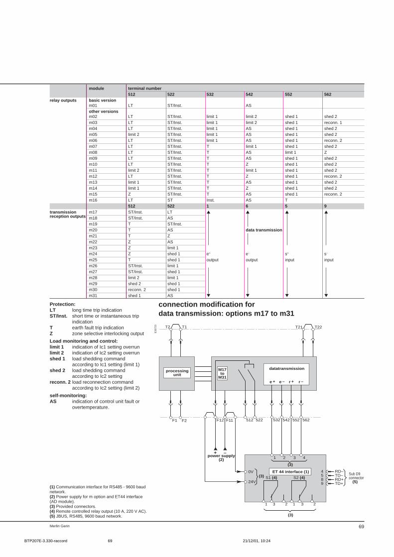
69Merlin Gerin
module terminal number512 522 532 542 552 562
relay outputs basic versionm01 LT ST/Inst. ASother versionsm02 LT ST/Inst. limit 1 limit 2 shed 1 shed 2m03 LT ST/Inst. limit 1 limit 2 shed 1 reconn. 1m04 LT ST/Inst. limit 1 AS shed 1 shed 2m05 limit 2 ST/Inst. limit 1 AS shed 1 shed 2m06 LT ST/Inst. limit 1 AS shed 1 reconn. 2m07 LT ST/Inst. T limit 1 shed 1 shed 2m08 LT ST/Inst. T AS limit 1 Zm09 LT ST/Inst. T AS shed 1 shed 2m10 LT ST/Inst. T Z shed 1 shed 2m11 limit 2 ST/Inst. T limit 1 shed 1 shed 2m12 LT ST/Inst. T Z shed 1 reconn. 2m13 limit 1 ST/Inst. T AS shed 1 shed 2m14 limit 1 ST/Inst. T Z shed 1 shed 2m15 Z ST/Inst. T AS shed 1 reconn. 2m16 LT ST Inst. AS T
512 522 1 6 5 9transmission m17 ST/Inst. LT reception outputs m18 ST/Inst. AS
m19 T ST/Inst.m20 T AS data transmissionm21 T Zm22 Z ASm23 Z limit 1m24 Z shed 1 e+ e– s+ s–
m25 T shed 1 output output input inputm26 ST/Inst. limit 1m27 ST/Inst. shed 1m28 limit 2 limit 1m29 shed 2 shed 1m30 reconn. 2 shed 1m31 shed 1 AS
Protection:LT long time trip indicationST/Inst. short time or instantaneous trip
indicationT earth fault trip indicationZ zone selective interlocking output
Load monitoring and control:limit 1 indication of Ic1 setting overrunlimit 2 indication of Ic2 setting overrunshed 1 load shedding command
according to Ic1 setting (limit 1)shed 2 load shedding command
according to Ic2 settingreconn. 2 load reconnection command
according to Ic2 setting (limit 2)
self-monitoring:AS indication of control unit fault or
overtemperature.
connection modification fordata transmission: options m17 to m31
T1T2
F1 F2
T21 T22
F11 522512F12
(3)
e + e – r + r –
542 562552532
2 431
(3)
S1 (4) S2 (4)
–+
0V
24V(3)
4589
RD–TD–RD+TD+ (5)
1 3 2 1 3 2
power supply(2)
Sub D9connector
ET 44 interface (1)
datatransmissionM17to
M31
processingunit
E30
723
(1) Communication interface for RS485 - 9600 baudnetwork.(2) Power supply for m option and ET44 interface(AD module).(3) Provided connectors.(4) Remote controlled relay output (10 A, 220 V AC).(5) JBUS, RS485, 9600 baud network.
BTP207E-3.330-raccord 21/12/01, 10:2469
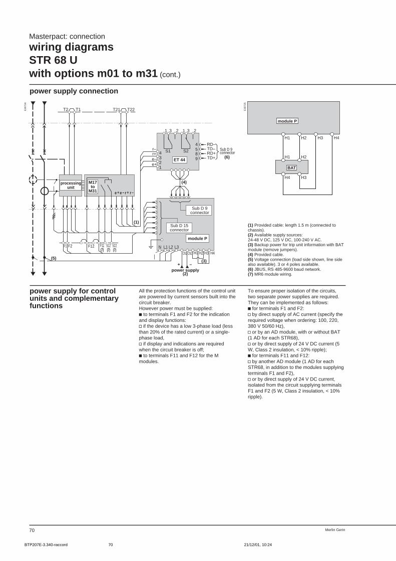
Merlin Gerin70
T1T2 T21 T22
(5)
512(7)
522(7)
F11(7)
e + e – r + r –
H4H3H2H1CN2
L3L2L1N
CN1
(3)
(4)
r–r+e–e+
4321
(6)
4589
RD–TD–RD+TD+
S1 S2
(1)
1 3 2 1 3 2
–+
F1 F2 F12
ET 44
module P
M17 to
M31
Sub D 15connector
power supply(2)
Sub D 9connector
Sub D 9connector
processingunit
Masterpact: connection
wiring diagramsSTR 68 Uwith options m01 to m31 (cont.)
power supply connection
E30
724
power supply for controlunits and complementaryfunctions
All the protection functions of the control unitare powered by current sensors built into thecircuit breaker.However power must be supplied:c to terminals F1 and F2 for the indicationand display functions:v if the device has a low 3-phase load (lessthan 20% of the rated current) or a single-phase load,v if display and indications are requiredwhen the circuit breaker is off;c to terminals F11 and F12 for the Mmodules.
E30
725
(1) Provided cable: length 1.5 m (connected tochassis).(2) Available supply sources:24-48 V DC, 125 V DC, 100-240 V AC.(3) Backup power for trip unit information with BATmodule (remove jumpers).(4) Provided cable.(5) Voltage connection (load side shown, line sidealso available). 3 or 4 poles available.(6) JBUS, RS 485-9600 baud network.(7) MR6 module wiring.
H1 H2 H3 H4
H1 H2
H4 H3
module P
BAT
To ensure proper isolation of the circuits,two separate power supplies are required.They can be implemented as follows:c for terminals F1 and F2:v by direct supply of AC current (specify therequired voltage when ordering: 100, 220,380 V 50/60 Hz),v or by an AD module, with or without BAT(1 AD for each STR68),v or by direct supply of 24 V DC current (5W, Class 2 insulation, < 10% ripple);c for terminals F11 and F12:v by another AD module (1 AD for eachSTR68, in addition to the modules supplyingterminals F1 and F2),v or by direct supply of 24 V DC current,isolated from the circuit supplying terminalsF1 and F2 (5 W, Class 2 insulation, < 10%ripple).
BTP207E-3.340-raccord 21/12/01, 10:2470
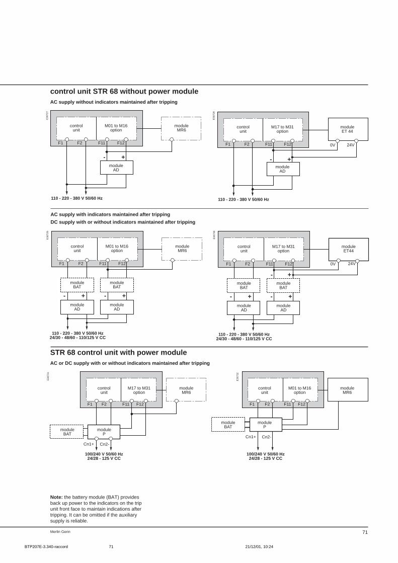
71Merlin Gerin
control unit STR 68 without power moduleAC supply without indicators maintained after tripping
110 - 220 - 380 V 50/60 Hz
- +
F1 F2 F11 F12
controlunit
M01 to M16option
moduleMR6
moduleAD
110 - 220 - 380 V 50/60 Hz
- +
F1 F2 F11 F12 0V 24V
controlunit
M17 to M31option
moduleET 44
moduleAD
AC supply with indicators maintained after tripping
DC supply with or without indicators maintained after tripping
110 - 220 - 380 V 50/60 Hz24/30 - 48/60 - 110/125 V CC
- +
F1 F2 F11 F12
- +
controlunit
M01 to M16option
moduleMR6
moduleBAT
moduleBAT
moduleAD
moduleAD
110 - 220 - 380 V 50/60 Hz24/30 - 48/60 - 110/125 V CC
- +
F1 F2 F11 F12
- +
- +
0V 24V
controlunit
M17 to M31option
moduleET44
moduleBAT
moduleBAT
moduleAD
moduleAD
STR 68 control unit with power moduleAC or DC supply with or without indicators maintained after tripping
100/240 V 50/60 Hz24/28 - 125 V CC
F1 F2 F11 F12
Cn2-Cn1+
controlunit
M17 to M31option
moduleMR6
moduleP
moduleBAT
100/240 V 50/60 Hz24/28 - 125 V CC
F1 F2 F11 F12
Cn2-Cn1+
controlunit
M01 to M16option
moduleMR6
moduleP
moduleBAT
E30
727
E30
728
E30
729
E30
730
E30
731
E30
732
Note: the battery module (BAT) providesback up power to the indicators on the tripunit front face to maintain indications aftertripping. It can be omitted if the auxiliarysupply is reliable.
BTP207E-3.340-raccord 21/12/01, 10:2471
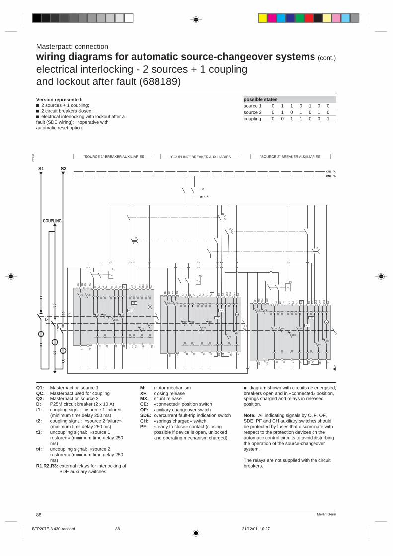
Merlin Gerin88
E33
097
possible statessource 1 0 1 1 0 1 0 0source 2 0 1 0 1 0 1 0coupling 0 0 1 1 0 0 1
Q1: Masterpact on source 1QC: Masterpact used for couplingQ2: Masterpact on source 2D: P25M circuit breaker (2 x 10 A)t1: coupling signal: «source 1 failure»
(minimum time delay 250 ms)t2: coupling signal: «source 2 failure»
(minimum time delay 250 ms)t3: uncoupling signal: «source 1
restored» (minimum time delay 250ms)
t4: uncoupling signal: «source 2restored» (minimum time delay 250ms)
R1,R2,R3: external relays for interlocking ofSDE auxiliary switches.
c diagram shown with circuits de-energised,breakers open and in «connected» position,springs charged and relays in releasedposition.
Note: All indicating signals by O, F, OF,SDE, PF and CH auxiliary switches shouldbe protected by fuses that discriminate withrespect to the protection devices on theautomatic control circuits to avoid disturbingthe operation of the source-changeoversystem.
The relays are not supplied with the circuitbreakers.
Masterpact: connection
wiring diagrams for automatic source-changeover systems (cont.)
electrical interlocking - 2 sources + 1 couplingand lockout after fault (688189)
M: motor mechanismXF: closing releaseMX: shunt releaseCE: «connected» position switchOF: auxiliary changeover switchSDE: overcurrent fault-trip indication switchCH: «springs charged» switchPF: «ready to close» contact (closing
possible if device is open, unlockedand operating mechanism charged).
Version represented:c 2 sources + 1 coupling;c 2 circuit breakers closed;c electrical interlocking with lockout after afault (SDE wiring): inoperative withautomatic reset option.
A
324
CE
322
314
312
SDE
MX
M
PF
CH
XF
82 84 C2
A4
252
254
262
B4
OF
32 34
321
311 81 31 C1 A1
251
B1
OFOF
2111
24221412
324
CE
322
314
312
SDE
MX
M
PF
CH
XF
82 84 C2
A4
252
254
262
B4
OF
32 34
321
311 81 31 C1 A1
251
B1
OFOF
2111
24221412
324
CE
322
314
312
SDE
MX
M
PF
CH
XF
82 84 C2
A4
252
254
262
B4
OF
32 34
321
311 81 31 C1 A1
251
B1
OFOF
2111
24221412
R1
S2
R2
R3
t4
t2
t1
t3
D
CN1
CN2
CE
CE
CE
S1
Q1
QC
Q2
COUPLING
"SOURCE 1" BREAKER AUXILIARIES "COUPLING" BREAKER AUXILIARIES "SOURCE 2" BREAKER AUXILIARIES
to A
BTP207E-3.430-raccord 21/12/01, 10:2788
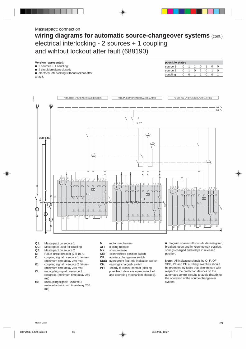
89Merlin Gerin
E33
098
possible statessource 1 0 1 1 0 1 0 0source 2 0 1 0 1 0 1 0coupling 0 0 1 1 0 0 1
c diagram shown with circuits de-energised,breakers open and in «connected» position,springs charged and relays in releasedposition.
Note: All indicating signals by O, F, OF,SDE, PF and CH auxiliary switches shouldbe protected by fuses that discriminate withrespect to the protection devices on theautomatic control circuits to avoid disturbingthe operation of the source-changeoversystem.
Q1: Masterpact on source 1QC: Masterpact used for couplingQ2: Masterpact on source 2D: P25M circuit breaker (2 x 10 A)t1: coupling signal: «source 1 failure»
(minimum time delay 250 ms)t2: coupling signal: «source 2 failure»
(minimum time delay 250 ms)t3: uncoupling signal: «source 1
restored» (minimum time delay 250ms)
t4: uncoupling signal: «source 2restored» (minimum time delay 250ms)
Masterpact: connection
wiring diagrams for automatic source-changeover systems (cont.)
electrical interlocking - 2 sources + 1 couplingand wihtout lockout after fault (688190)
M: motor mechanismXF: closing releaseMX: shunt releaseCE: «connected» position switchOF: auxiliary changeover switchSDE: overcurrent fault-trip indication switchCH: «springs charged» switchPF: «ready to close» contact (closing
possible if device is open, unlockedand operating mechanism charged).
Version represented:c 2 sources + 1 coupling;c 2 circuit breakers closed;c electrical interlocking without lockout aftera fault.
t4
t2
t1
t3
324
CE
322
314
312
MX
M
PF
CH
XFC
2
A4
252
254
262
B4
OF
32 34
321
311 31 C1 A1
251
B1
OFOF
2111
24221412
324
CE
322
314
312
MX
M
PF
CH
XF
C2
A4
252
254
262
B4
OF
32 34
321
311 31 C1 A1
251
B1
OFOF
2111
24221412
324
CE
322
314
312
MX
M
PF
CH
XF
C2
A4
252
254
262
B4
OF
32 34
321
311 31 C1 A1
251
B1
OFOF
2111
24221412
A
S1
D
CN1
CN2
S2
Q1
QC
Q2
COUPLING
"SOURCE 1" BREAKER AUXILIARIES "COUPLING" BREAKER AUXILIARIES "SOURCE 2" BREAKER AUXILIARIES
to A
BTP207E-3.430-raccord 21/12/01, 10:2789
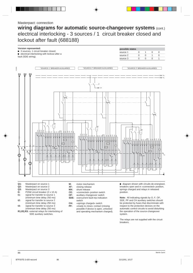
Merlin Gerin86
possible statessource 1 0 1 0 0source 2 0 0 1 0source 3 0 0 0 1
E33
095
Q1: Masterpact on source 1Q2: Masterpact on source 2Q3: Masterpact on source 3D: P25M circuit breaker (2 x 10 A)t1: signal for transfer to source 1
(minimum time delay 250 ms)t2: signal for transfer to source 2
(minimum time delay 250 ms)t3: signal for transfer to source 3
(minimum time delay 250 ms)R1,R2,R3: external relays for interlocking of
SDE auxiliary switches.
c diagram shown with circuits de-energised,breakers open and in «connected» position,springs charged and relays in releasedposition.
Note: All indicating signals by O, F, OF,SDE, PF and CH auxiliary switches shouldbe protected by fuses that discriminate withrespect to the protection devices on theautomatic control circuits to avoid disturbingthe operation of the source-changeoversystem.
The relays are not supplied with the circuitbreakers.
Masterpact: connection
wiring diagrams for automatic source-changeover systems (cont.)
electrical interlocking - 3 sources / 1 circuit breaker closed andlockout after fault (688188)Version represented:c 3 sources, 1 circuit breaker closed;c electrical interlocking with lockout after afault (SDE wiring).
M: motor mechanismXF: closing releaseMX: shunt releaseCE: «connected» position switchOF: auxiliary changeover switchSDE: overcurrent fault-trip indication
switchCH: «springs charged» switchPF: «ready to close» contact (closing
possible if device is open, unlockedand operating mechanism charged).
A
324
CE
322
314
312
SDE
MX
M
PF
CH
XF
82 84 C2
A4
252
254
262
B4
OF
32 34
321
311 81 31 C1
A1
251
B1
OFOF
2111
24221412
324
CE
322
314
312
SDE
MX
M
PF
CH
XF
82 84 C2
A4
252
254
262
B4
OF
32 34
321
311 81 31 C1
A1
251
B1
OFOF
2111
24221412
R1
S1
R2
R3
t3
t2
t1
D
CN1
CN2
324
CE
322
314
312
SDE
MX
M
PF
CH
XF
82 84 C2
A4
252
254
262
B4
OF
32 34
321
311 81 31 C1
A1
251
B1
OFOF
2111
24221412
CE
CE
CE
S2 S3
Q2
Q3
Q1
"SOURCE 1" BREAKER AUXILIARIES "SOURCE 2" BREAKER AUXILIARIES "SOURCE 3" BREAKER AUXILIARIES
to A
BTP207E-3.420-raccord 21/12/01, 10:2786

87Merlin Gerin
possible statessource 1 0 1 0 0source 2 0 0 1 0source 3 0 0 0 1
E33
096
Q1: Masterpact on source 1Q2: Masterpact on source 2Q3: Masterpact on source 3D: P25M circuit breaker (2 x 10 A)t1: signal for transfer to source 1
(minimum time delay 250 ms)t2: signal for transfer to source 2
(minimum time delay 250 ms)t3: signal for transfer to source 3
(minimum time delay 250 ms)
c diagram shown with circuits de-energised,breakers open and in «connected» position,springs charged and relays in releasedposition.
Note: All indicating signals by O, F, OF,SDE, PF and CH auxiliary switches shouldbe protected by fuses that discriminate withrespect to the protection devices on theautomatic control circuits to avoid disturbingthe operation of the source-changeoversystem.
Masterpact: connection
wiring diagrams for automatic source-changeover systems (cont.)
electrical interlocking - 3 sources / 1 circuit breaker closed andwithout lockout after fault (688187)
Version represented:c 3 sources, 1 circuit breaker closed;c electrical interlocking without lockout aftera fault.
M: motor mechanismXF: closing releaseMX: shunt releaseCE: «connected» position switchOF: auxiliary changeover switchSDE: overcurrent fault-trip indication switchCH: «springs charged» switchPF: «ready to close» contact (closing
possible if device is open, unlockedand operating mechanism charged).
324
CE
322
314
312
MX
M
PF
CH
XF
C2
A4
252
254
262
B4
OF32 34
321
311 31 C1
A1
251
B1
OFOF
2111
24221412
324
CE
322
314
312
MX
M
PF
CH
XF
C2
A4
252
254
262
B4
OF
32 34
321
311 31 C1
A1
251
B1
OFOF
2111
24221412
324
CE
322
314
312
MX
M
PF
CH
XF
C2
A4
252
254
262
B4
OF
32 34
321
311 31 C1
A1
251
B1
OFOF
2111
24221412
A
S1
t3
t2
t1
D
CN1
CN2
S2 S3
Q1
Q2
Q3
"SOURCE 1" BREAKER AUXILIARIES "SOURCE 2" BREAKER AUXILIARIES "SOURCE 3" BREAKER AUXILIARIES
to A
BTP207E-3.420-raccord 21/12/01, 10:2787
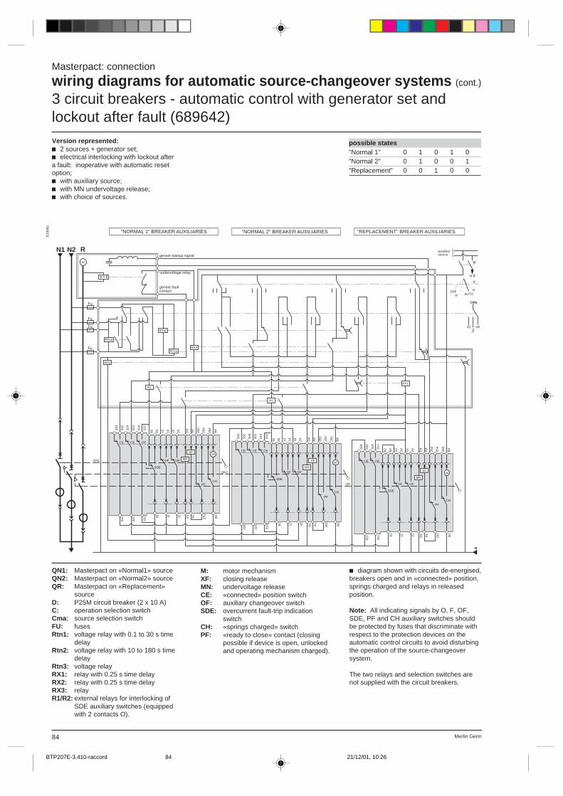
Merlin Gerin84
Masterpact: connection
wiring diagrams for automatic source-changeover systems (cont.)
3 circuit breakers - automatic control with generator set andlockout after fault (689642)
possible states"Normal 1" 0 1 0 1 0"Normal 2" 0 1 0 0 1"Replacement" 0 0 1 0 0
E33
093
QN1: Masterpact on «Normal1» sourceQN2: Masterpact on «Normal2» sourceQR: Masterpact on «Replacement»
sourceD: P25M circuit breaker (2 x 10 A)C: operation selection switchCma: source selection switchFU: fusesRtn1: voltage relay with 0.1 to 30 s time
delayRtn2: voltage relay with 10 to 180 s time
delayRtn3: voltage relayRX1: relay with 0.25 s time delayRX2: relay with 0.25 s time delayRX3: relayR1/R2: external relays for interlocking of
SDE auxiliary switches (equippedwith 2 contacts O).
c diagram shown with circuits de-energised,breakers open and in «connected» position,springs charged and relays in releasedposition.
Note: All indicating signals by O, F, OF,SDE, PF and CH auxiliary switches shouldbe protected by fuses that discriminate withrespect to the protection devices on theautomatic control circuits to avoid disturbingthe operation of the source-changeoversystem.
The two relays and selection switches arenot supplied with the circuit breakers.
M: motor mechanismXF: closing releaseMN: undervoltage releaseCE: «connected» position switchOF: auxiliary changeover switchSDE: overcurrent fault-trip indication
switchCH: «springs charged» switchPF: «ready to close» contact (closing
possible if device is open, unlockedand operating mechanism charged).
Version represented:c 2 sources + generator set;c electrical interlocking with lockout aftera fault: inoperative with automatic resetoption;c with auxiliary source;c with MN undervoltage release;c with choice of sources.
334
CE
332
324
CE
322
314
CE
312
82 84
SDE
OF OF MN
M
PFCH
XF
12 14 22 24 D4
A4
252
254
262
B4
324
CE
322
314
CE
312
82 84
SDE
OF
MN
M
PFCH
XF
12 14 D4
A4
252
254
262
B4
334
CE
332
324
CE
322
314
CE
312
82 84
SDE
OF OF
MN
M
PF
CH
12 14 22 24 D4
A4
252
254
262
B4
OF
22 24
R2
R1
RX2
RX3
RTn2
RTn3
RTn1
B
U = 0
G
XF
331
321
311 81 11 21 D1 A1
251
B1
331
321
311 81 11 21 D1 A1
251
B1
321
311 81 11 21 D1 A1
251
B1
C
NAUTO
OFF
D
CMa
N1 N2
N1-
2
RX1
Fu
Fu
Fu
Fu
N2N1
QN1
QN2
QR
R
"NORMAL 1" BREAKER AUXILIARIES
genset startup signal
undervoltage relay
genset faultcontact
"NORMAL 2" BREAKER AUXILIARIES "REPLACEMENT" BREAKER AUXILIARIES
auxiliary source
to B
R
BTP207E-3.410-raccord 21/12/01, 10:2684

85Merlin Gerin
possible states"Normal 1" 0 1 0 1 0"Normal 2" 0 1 0 0 1"replacement" 0 0 1 0 0
E33
094
Masterpact: connection
wiring diagrams for automatic source-changeover systems (cont.)
3 circuit breakers - automatic control with generator set andwithout lockout after fault (689644)
M: motor mechanismXF: closing releaseMN: undervoltage releaseCE: «connected» position switchOF: auxiliary changeover switchSDE: overcurrent fault-trip indication
switchCH: «springs charged» switchPF: «ready to close» contact (closing
possible if device is open, unlockedand operating mechanism charged).
Version represented:c 2 sources + generator set;c electrical interlocking with lockout after afault: inoperative with automatic resetoption;c with auxiliary source;c with MN undervoltage release;c with choice of sources.
QN1: Masterpact on «Normal1» sourceQN2: Masterpact on «Normal2» sourceQR: Masterpact on «Replacement»
sourceD: P25M circuit breaker (2 x 10 A)C: operation selection switchCma: source selection switchFU: fusesRtn1: voltage relay with 0.1 to 30 s time
delayRtn2: voltage relay with 10 to 180 s time
delayRtn3: voltage relayRX1: relay with 0.25 s time delayRX2: relay with 0.25 s time delayRX3: relay
c diagram shown with circuits de-energised,breakers open and in «connected» position,springs charged and relays in releasedposition.
Note: All indicating signals by O, F, OF,SDE, PF and CH auxiliary switches shouldbe protected by fuses that discriminate withrespect to the protection devices on theautomatic control circuits to avoid disturbingthe operation of the source-changeoversystem.
The relays and selection switches are notsupplied with the circuit breakers.
324
CE
322
314
CE
312
82 84
SDE
OF OF MN
M
PFCH
XF
12 14 22 24 D4
A4
252
254
262
B4
324
CE
322
314
CE
312
82 84
SDE
OF
MN
M
PFCH
XF
12 14 D4
A4
252
254
262
B4
324
CE
322
314
CE
312
82 84
SDE
OF OF
MN
M
PF
CH
12 14 22 24 D4
A4
252
254
262
B4
OF
22 24
R2
R1
RX2
RX3
RTn2
RTn3
RTn1
B
U = 0
G
XF
321
311 81 11 21 D1 A1
251
B1
321
311 81 11 21 D1 A1
251
B1
321
311 81 11 21 D1 A1
251
B1
C
NAUTO
OFF
D
CMa
N1 N2
N1-
2
RX1
Fu
Fu
Fu
Fu
N1 N2
QN1
QN2
QR
R
"NORMAL 1" BREAKER AUXILIARIES
genset startup signal
undervoltage relay
genset faultcontact
"NORMAL 2" BREAKER AUXILIARIES "REPLACEMENT" BREAKER AUXILIARIES
auxiliarysource
to B
R
BTP207E-3.410-raccord 21/12/01, 10:2685

Merlin Gerin82
Masterpact: connection
wiring diagrams for automatic source-changeover systems (cont.)
3 circuit breakers - automatic control with permanent "Replacement"source and lockout after fault (685366)
possible states"Normal 1" 0 1 0 1 0"Normal 2" 0 1 0 0 1"Replacement" 0 0 1 0 0
E33
091
Version represented:c 2 «Normal» sources + 1 «Replacement»source;c electrical interlocking with lockout after afault (SDE wiring): inoperative withautomatic reset option.
QN1: Masterpact on «Normal1» sourceQN2: Masterpact on «Normal2» sourceQR: Masterpact on «Replacement»
sourceD: P25M circuit breaker (2 x 10 A)t1: signal for transfer to «Normal1» and
«Normal2» sources (minimum timedelay 250 ms)
t1: signal for transfer to «Replacement»source (minimum time delay 250 ms)
R1/R2:external relays for interlocking ofSDE auxiliary switches (equippedwith 2 contacts O).
M: motor mechanismXF: closing releaseMX: shunt releaseCE: «connected» position switchOF: auxiliary changeover switchSDE: overcurrent fault-trip indication switchCH: «springs charged» switchPF: «ready to close» contact (closing
possible if device is open, unlockedand operating mechanism charged).
c diagram shown with circuits de-energised,breakers open and in «connected» position,springs charged and relays in releasedposition.
Note: All indicating signals by O, F, OF,SDE, PF and CH auxiliary switches shouldbe protected by fuses that discriminate withrespect to the protection devices on theautomatic control circuits to avoid disturbingthe operation of the source-changeoversystem.
(1) The two relays are not supplied with thecircuit breakers.
A
CE
314
312
SDE
MX
M
PF
CH
XF
82 84 C2
A4
252
254
262
B4
OF
22 24
311 81 21 C1 A1
251
B1
OF
111412
N1 N2
R2 (1)
D
CN1
CN2
CE
314
312
SDE
MX
M
PF
CH
XF
82 84 C2
A4
252
254
262
B4
OF
22 24
311 81 21 C1 A1
251
B1
OF
111412CE
314
312
SDE
MX
M
PFCH
XF
82 84 C2
A4
252
254
262
B4
OF
22 24
311 81 21 C1 A1
251
B1
OF
111412
R1 (1)
t1
t2
QN1
QN2
QR
R
"NORMAL 1" BREAKER AUXILIARIES "NORMAL 2" BREAKER AUXILIARIES "REPLACEMENT" BREAKER AUXILIARIES
to A
BTP207E-3.400-raccord 21/12/01, 10:2682
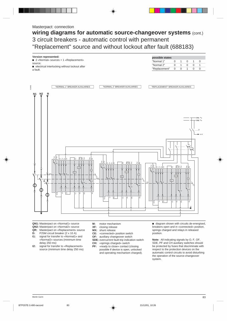
83Merlin Gerin
possible states"Normal 1" 0 1 0 1 0"Normal 2" 0 1 0 0 1"Replacement" 0 0 1 0 0
E33
092
QN1: Masterpact on «Normal1» sourceQN2: Masterpact on «Normal2» sourceQR: Masterpact on «Replacement» sourceD: P25M circuit breaker (2 x 10 A)t1: signal for transfer to «Normal1» and
«Normal2» sources (minimum timedelay 250 ms)
t2: signal for transfer to «Replacement»source (minimum time delay 250 ms)
c diagram shown with circuits de-energised,breakers open and in «connected» position,springs charged and relays in releasedposition.
Note: All indicating signals by O, F, OF,SDE, PF and CH auxiliary switches shouldbe protected by fuses that discriminate withrespect to the protection devices on theautomatic control circuits to avoid disturbingthe operation of the source-changeoversystem.
Masterpact: connection
wiring diagrams for automatic source-changeover systems (cont.)
3 circuit breakers - automatic control with permanent"Replacement" source and without lockout after fault (688183)
Version represented:c 2 «Normal» sources + 1 «Replacement»source;c electrical interlocking without lockout aftera fault.
M: motor mechanismXF: closing releaseMX: shunt releaseCE: «connected» position switchOF: auxiliary changeover switchSDE: overcurrent fault-trip indication switchCH: «springs charged» switchPF: «ready to close» contact (closing
possible if device is open, unlockedand operating mechanism charged).
CE
314
312
MX
M
PFCH
XF
C2
A4
252
254
262
B4
OF
22 24
311 21 C1 A1
251
B1
OF
111412CE
314
312
MX
M
PFCH
XF
C2
A4
252
254
262
B4
OF
22 24
311 21 C1 A1
251
B1
OF
111412CE
314
312
MX
M
PFCH
XF
C2
A4
252
254
262
B4
OF
22 24
311 21 C1 A1
251
B1
OF
111412
A
N1 N2
D
CN1
CN2
t1
t2
QN1
QN2
QR
R
"NORMAL 1" BREAKER AUXILIARIES "NORMAL 2" BREAKER AUXILIARIES "REPLACEMENT" BREAKER AUXILIARIES
to A
BTP207E-3.400-raccord 21/12/01, 10:2683
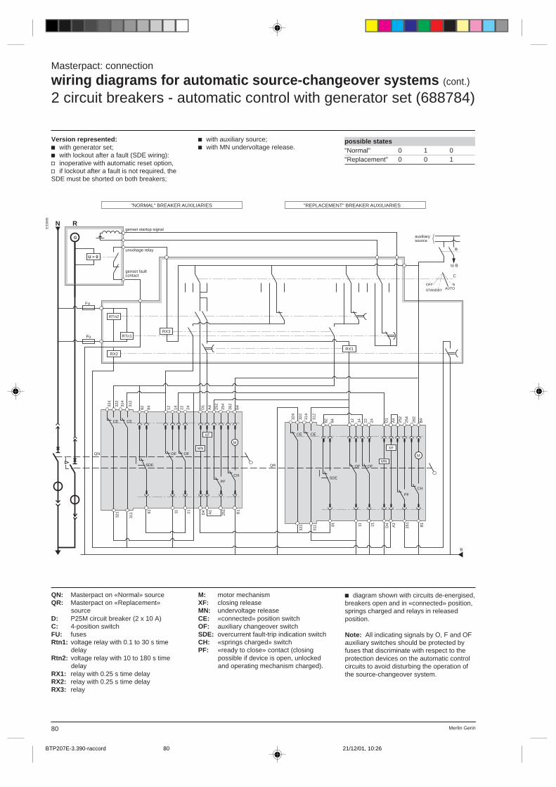
Merlin Gerin80
Masterpact: connection
wiring diagrams for automatic source-changeover systems (cont.)
2 circuit breakers - automatic control with generator set (688784)
possible states"Normal" 0 1 0"Replacement" 0 0 1
E33
089
QN: Masterpact on «Normal» sourceQR: Masterpact on «Replacement»
sourceD: P25M circuit breaker (2 x 10 A)C: 4-position switchFU: fusesRtn1: voltage relay with 0.1 to 30 s time
delayRtn2: voltage relay with 10 to 180 s time
delayRX1: relay with 0.25 s time delayRX2: relay with 0.25 s time delayRX3: relay
M: motor mechanismXF: closing releaseMN: undervoltage releaseCE: «connected» position switchOF: auxiliary changeover switchSDE: overcurrent fault-trip indication switchCH: «springs charged» switchPF: «ready to close» contact (closing
possible if device is open, unlockedand operating mechanism charged).
Version represented:c with generator set;c with lockout after a fault (SDE wiring):v inoperative with automatic reset option,v if lockout after a fault is not required, theSDE must be shorted on both breakers;
c diagram shown with circuits de-energised,breakers open and in «connected» position,springs charged and relays in releasedposition.
Note: All indicating signals by O, F and OFauxiliary switches should be protected byfuses that discriminate with respect to theprotection devices on the automatic controlcircuits to avoid disturbing the operation ofthe source-changeover system.
c with auxiliary source;c with MN undervoltage release.
RX2
RTn2
RTn1RX3
C
NAUTO
OFF
U = 0
G
D
Fu
Fu
B
314
CE
312
324
322
SDE
MN
M
PF
CH
XF
82 84 D1
A4
252
254
262
B4
311
321 81 D4 A1
251
B1
OFOF
2111
24221412
CE
314
CE
312
324
322
SDE
MN
M
PF
CH
XF
82 84 D1
A4
252
254
262
B4
311
321 81 D4 A1
251
B1
OFOF
2111
24221412
CE
RX1
N
QN
QR
Rgenset startup signal
"NORMAL" BREAKER AUXILIARIES
unvoltage relay
genset fault contact
"REPLACEMENT" BREAKER AUXILIARIES
auxiliary source
to B
STANDBY
BTP207E-3.390-raccord 21/12/01, 10:2680
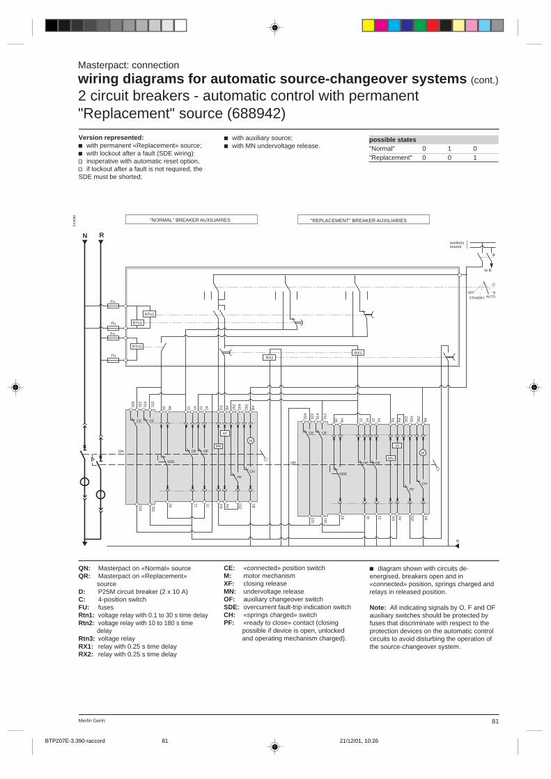
81Merlin Gerin
possible states"Normal" 0 1 0"Replacement" 0 0 1
E33
090
QN: Masterpact on «Normal» sourceQR: Masterpact on «Replacement»
sourceD: P25M circuit breaker (2 x 10 A)C: 4-position switchFU: fusesRtn1: voltage relay with 0.1 to 30 s time delayRtn2: voltage relay with 10 to 180 s time
delayRtn3: voltage relayRX1: relay with 0.25 s time delayRX2: relay with 0.25 s time delay
CE: «connected» position switchM: motor mechanismXF: closing releaseMN: undervoltage releaseOF: auxiliary changeover switchSDE: overcurrent fault-trip indication switchCH: «springs charged» switchPF: «ready to close» contact (closing
possible if device is open, unlockedand operating mechanism charged).
Masterpact: connection
wiring diagrams for automatic source-changeover systems (cont.)
2 circuit breakers - automatic control with permanent"Replacement" source (688942)
c diagram shown with circuits de-energised, breakers open and in«connected» position, springs charged andrelays in released position.
Note: All indicating signals by O, F and OFauxiliary switches should be protected byfuses that discriminate with respect to theprotection devices on the automatic controlcircuits to avoid disturbing the operation ofthe source-changeover system.
Version represented:c with permanent «Replacement» source;c with lockout after a fault (SDE wiring):v inoperative with automatic reset option,v if lockout after a fault is not required, theSDE must be shorted;
c with auxiliary source;c with MN undervoltage release.
N
RTn1
RTn2
RX1
D
C
NAUTO
OFF
Fu
Fu
B
RX2
RTn3
Fu
Fu
314
CE
312
324
322
SDE
MN
M
PF
CH
XF
82 84 D1
A4
252
254
262
B4
311
321 81 D4 A1
251
B1
OFOF
2111
24221412
314
CE
312
324
322
SDE
MN
M
PF
CH
XF
82 84 D1
A4
252
254
262
B4
311
321 81 D4 A1
251
B1
OFOF
2111
24221412
CE
CE
QN
QR
R
"NORMAL" BREAKER AUXILIARIES "REPLACEMENT" BREAKER AUXILIARIES
auxiliary source
to B
STANDBY
BTP207E-3.390-raccord 21/12/01, 10:2681
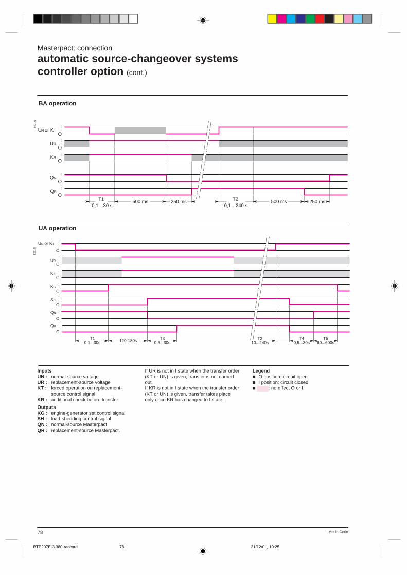
Merlin Gerin78
Masterpact: connection
automatic source-changeover systemscontroller option (cont.)
E27
121
UA operation
E30
189
BA operation
I
OI
OI
O
0,1…30 sT1 500 ms 250 ms
I
OI
O
UN T
UR
KR
QN
QR
250 ms 500 ms 0,1…240 s
T2
or K
T10,1...30s
I
O
I
O
I
O
I
O
I
O
I
O
I
O
UR
KR
KG
SH
QN
QR
120-180s T30,5...30s
T210...240s
T40,5...30s
T560...600s
UN or KT
InputsUN : normal-source voltageUR : replacement-source voltageKT : forced operation on replacement-
source control signalKR : additional check before transfer.
OutputsKG : engine-generator set control signalSH : load-shedding control signalQN : normal-source MasterpactQR : replacement-source Masterpact.
If UR is not in I state when the transfer order(KT or UN) is given, transfer is not carriedout.If KR is not in I state when the transfer order(KT or UN) is given, transfer takes placeonly once KR has changed to I state.
Legendc O position: circuit openc I position: circuit closedc : no effect O or I.
BTP207E-3.380-raccord 21/12/01, 10:2578

79Merlin Gerin
Masterpact: connection
wiring diagrams for automatic source-changeover systems2 circuit breakers - electrical interlocking (685363)
E33
088
Version represented: With lockout after afault.If lockout after a fault is not required, contactPF of the «Normal» breaker must beconnected directly in series with auxiliaryswitch OF of the «Replacement» breakerand vice versa, without passing through theswitch SDE.
The indication circuits, represented on thediagram by broken lines, are optional.Accessories such as voltage relays,indicating lights and fuses are not suppliedwith the circuit breaker.
possible states"Normal" 0 1 0"Replacement" 0 0 1
QN: Masterpact on «Normal» sourceQR: Masterpact on «Replacement» sourceD: P25M circuit breaker (2 x 10 A)F1, F2, F3, F4: protective fuses 2 ARts: «Replacement» source voltage relay
(minimum time delay 250 ms)Rtn: «Normal» source voltage relay
(minimum time delay 250 ms)
M: motor mechanismXF: closing releaseMX: shunt releaseCE: «connected» position switchOF: auxiliary changeover switchSDE:overcurrent fault-trip indication switchCH: «springs charged» switchPF: «ready to close» contact (closing
possible if device is open, unlockedand operating mechanism charged).
c diagram shown with circuits de-energised,breakers open and in «connected» position,springs charged and relays in releasedposition.
(1) The fuses clear faults occurring on theindication circuits without disturbing theoperation of the source-changeover system.(2) Terminal 84 does not exist on controlunits STR58 with options Z and/or C orSTR68UM/UTM; in this case there isdiscrimination between the indications.
CE
314
312
SDE
MX
M
PF
CH
XF
82 84 C2
A4
252
254
262
B4
OF
22 24
311 81 21 C1 A1
251 B1
OF
111412
A
B
F3 (1)
F2 (1)F1 (1)
F4 (1)
C
D
RTs
RTn
CN1
CN2
(2)
(2)
CE
314
312
SDE
MX
M
PF
CH
82 84 C2
A4
252
254
262
B4
OF
22 24
311 81 21 C1 A1
251 B1
OF
111412
XF
N R
QN
QR
"NORMAL" BREAKER AUXILIARIES "REPLACEMENT" BREAKER AUXILIARIES CONTROL PRINCIPLE
closed
open
fault
to A
closed
open
fault
to B
to C
controlvoltage
BTP207E-3.380-raccord 21/12/01, 10:2579
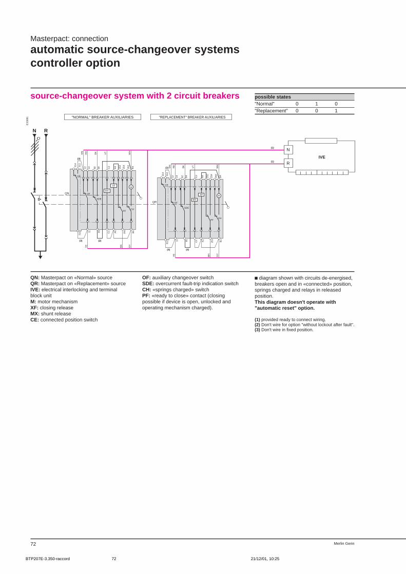
Merlin Gerin72
Masterpact: connection
automatic source-changeover systemscontroller option
source-changeover system with 2 circuit breakers
E33
081
possible states"Normal" 0 1 0"Replacement" 0 0 1
QN
314
CE
312
M
PFCH
252
254
262
B4
311 25
1
B1
82 84
SDE
81
OF
12 1411
MX
C2
C1
XF
A4
A1
N R
GN
RD
BK
VT
WH
GN
RD
BK
VT
WH
YE
BN
GY
YE
BN
GY
314
CE
312
M
PFCH
252
254
262
B4
311 25
1
B1
82 84
SDE
81
OF
12 1411
MX
C2
C1
XF
A4
A1(3) (2)
(3)
QR
(3)
(3) (2)
(1)
(1)
"NORMAL" BREAKER AUXILIARIES "REPLACEMENT" BREAKER AUXILIARIES
IVE
N
R
QN: Masterpact on «Normal» sourceQR: Masterpact on «Replacement» sourceIVE: electrical interlocking and terminalblock unitM: motor mechanismXF: closing releaseMX: shunt releaseCE: connected position switch
OF: auxiliary changeover switchSDE: overcurrent fault-trip indication switchCH: «springs charged» switchPF: «ready to close» contact (closingpossible if device is open, unlocked andoperating mechanism charged).
c diagram shown with circuits de-energised,breakers open and in «connected» position,springs charged and relays in releasedposition.This diagram doesn't operate with"automatic reset" option.
(1) provided ready to connect wiring.(2) Don't wire for option "without lockout after fault".(3) Don't wire in fixed position.
BTP207E-3.350-raccord 21/12/01, 10:2572
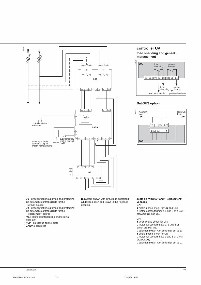
73Merlin Gerin
ACP
24 N O L 9 10 R E 25
IVEN
R
24 N O L
BA/UA
R E 25
N R
Q1
1
2
3
4
5
6
Q2
1
2
3
4
5
6
1718
2021
11 12 13 14 15 16
1 2 3 4 5 6 7 8 9 10
1211 13 14 15 16 10 9 8 7 6 5
2322
controller statusindication
voluntary transfercommand (e.j. forenergy management)
supplementarycontrol contactNR
E33
075
controller UAload shedding and gensetmanagement
BatiBUS option
E33
077
E33
076
UA
23 22 27 26 28 30 29 31
loadshedding
genset shutdown
loadshedding
gensetstartup
gensetstartup
load reconnection
UA
+–0V24V
+ – 0V 24V
BatiBUSloop
BatiBUSloop
Q1 : circuit breaker supplying and protectingthe automatic control circuits for the"Normal" sourceQ2 : circuit breaker supplying and protectingthe automatic control circuits for the"Replacement" sourceIVE : electrical interlocking and terminalblock unitACP : auxiliaries control plateBA/UA : controller
c diagram shown with circuits de-energised,all devices open and relays in the releasedposition.
Tests on "Normal" and "Replacement"voltagesBA:c single-phase check for UN and UR:v tested across terminals 1 and 5 of circuitbreakers Q1 and Q2.
UA:c three-phase check for UN:v tested across terminals 1, 3 and 5 ofcircuit breaker Q1,v selection switch A of controller set to 1;c single-phase check for UN :v tested across terminals 1 and 5 of circuitbreaker Q1,v selection switch A of controller set to 0.
BTP207E-3.350-raccord 21/12/01, 10:2573

Merlin Gerin90
S1
Fu
Fu
Fu
Fu
Fu
Fu
CMa
CMb
OF
Fau
to
N1+
CN
1+N
2N
2+C
314
CE
312
324
322
SDE
MX
M
PFCH
XF
82 84 C2
A4
252
254
262
B4
OF
22 24
311
321 81 21 C1 A1
251
B1
OF
111412
CE 314
CE
312
324
322
SDE
MX
M
PF
CH
XF
82 84 C2
A4
252
254
262
B4
OF
22 24
311
321 81 21 C1 A1
251
B1
OF
111412
CE
314
CE
312
324
322
SDE
MX
M
PF
CH
XF
82 84 C2
A4
252
254
262
B4
OF
22 24
311
321 81 21 C1 A1
251
B1
OF
111412
CE
S2
RTn1
RTn2
RTn3
RTn4
RX1
RX2
RX3
COUPLER
"SOURCE 1" BREAKER AUXILIARIES "COUPLING" BREAKER AUXILIARIES "SOURCE 2" BREAKER AUXILIARIES
perm
anen
t
possible statessource 1 0 1 0 0 1 0 1source 2 0 0 1 0 1 1 0coupling 0 0 0 1 0 1 1
E33
099
c diagram shown with circuits de-energised,breakers open and in «connected» position,springs charged and relays in releasedposition.
Note: All indicating signals by O, F, OF,SDE, PF and CH auxiliary switches shouldbe protected by fuses that discriminate withrespect to the protection devices on theautomatic control circuits to avoid disturbingthe operation of the source-changeoversystem.
The relays are not supplied with the circuitbreakers.
Q1: Masterpact on source 1QC: Masterpact used for couplingQ2: Masterpact on source 2Cma: 3-position switchFU: fusesRtn1: voltage relay with 10 to 180 s time
delayRtn2: voltage relay with 0.1 to 30 s time
delayRtn3: voltage relay with 10 to 180 s time
delayRtn4: voltage relay with 0.1 to 30 s time
delayCmb: coupling selection switchRX1: relay with 0.25 s time delayRX2: relay with 0.25 s time delayRX3: relay with 0.25 s time delay
Masterpact: connection
wiring diagrams for automatic source-changeover systems (cont.)
automatic control - 2 sources + 1 couplingand lockout after fault (689651)
Version represented:c 2 sources + 1 coupling;c 2 circuit breakers closed;c electrical interlocking with lockout after afault: inoperative with automatic resetoption.
M: motor mechanismXF: closing releaseMX: shunt releaseCE: «connected» position switchOF: auxiliary changeover switchSDE: overcurrent fault-trip indication
switchCH: «springs charged» switchPF: «ready to close» contact (closing
possible if device is open, unlockedand operating mechanism charged).
BTP207E-3.440-raccord 21/12/01, 10:2890

77
LV power aircircuit breakersand switch-disconnectors
Masterpact
4/ complementary technicalinformation
page
tripping curves 0effect of ambient temperature 0
BTP207E-4.001-sommaire 21/12/01, 10:2977
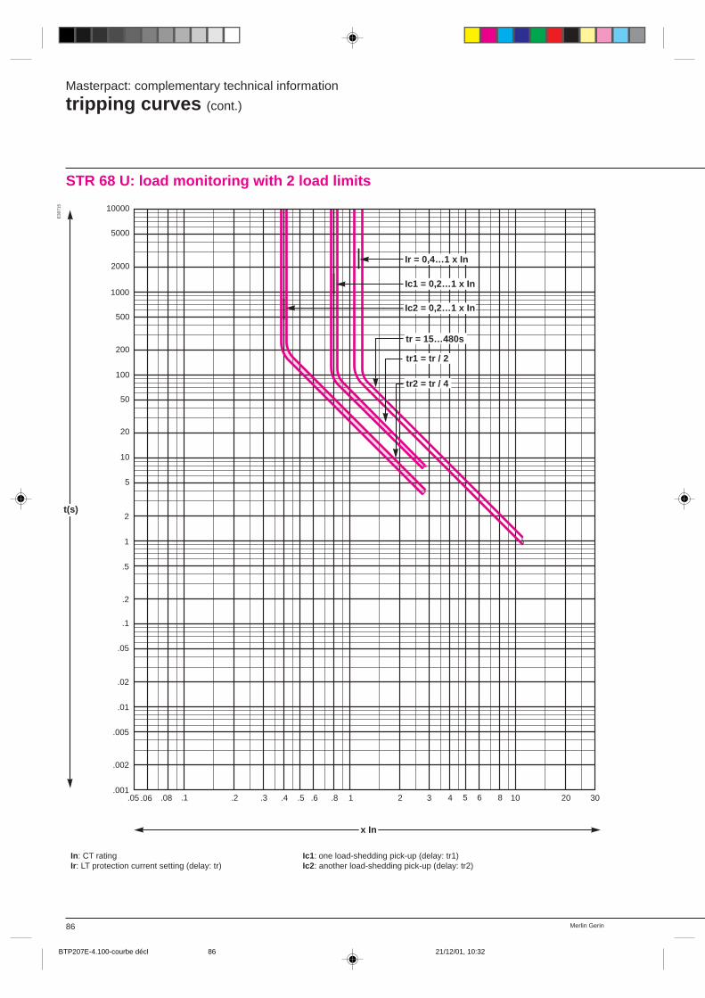
Merlin Gerin86
Masterpact: complementary technical information
tripping curves (cont.)
.05 .06 .08 .1 .2 .3 .4 .5 .6 .8 1 2 3 4 5 6 8 10 20 30.001
.002
.01
.02
.05
.1
.2
.5
1
2
5
10
20
.005
50
100
200
500
1000
2000
5000
10000
tr = 15…480s
Ir = 0,4…1 x In
Ic1 = 0,2…1 x In
Ic2 = 0,2…1 x In
tr1 = tr / 2
tr2 = tr / 4
t(s)
x In
Ic1: one load-shedding pick-up (delay: tr1)Ic2: another load-shedding pick-up (delay: tr2)
In: CT ratingIr: LT protection current setting (delay: tr)
E30
715
STR 68 U: load monitoring with 2 load limits
BTP207E-4.100-courbe décl 21/12/01, 10:3286
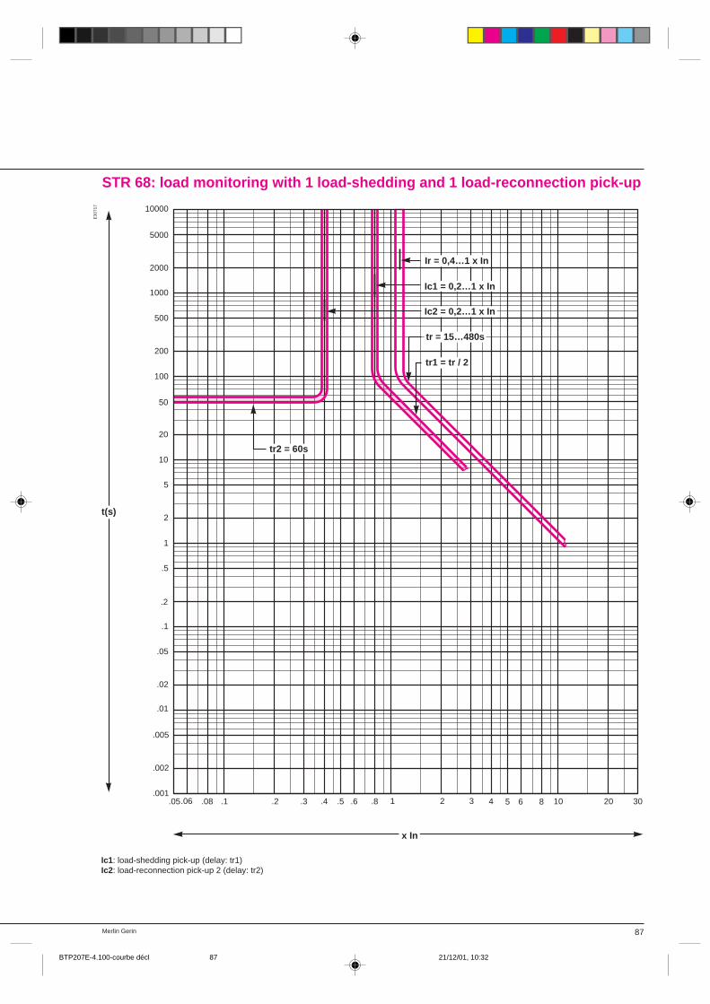
87Merlin Gerin
STR 68: load monitoring with 1 load-shedding and 1 load-reconnection pick-up
E30
717
.05.06 .08 .1 .2 .3 .4 .5 .6 .8 1 2 3 4 5 6 8 10 20 30.001
.002
.01
.02
.05
.1
.2
.5
1
2
5
10
20
.005
50
100
200
500
1000
2000
5000
10000
tr = 15…480s
Ir = 0,4…1 x In
Ic1 = 0,2…1 x In
Ic2 = 0,2…1 x In
tr1 = tr / 2
tr2 = 60s
t(s)
x In
Ic1: load-shedding pick-up (delay: tr1)Ic2: load-reconnection pick-up 2 (delay: tr2)
BTP207E-4.100-courbe décl 21/12/01, 10:3287
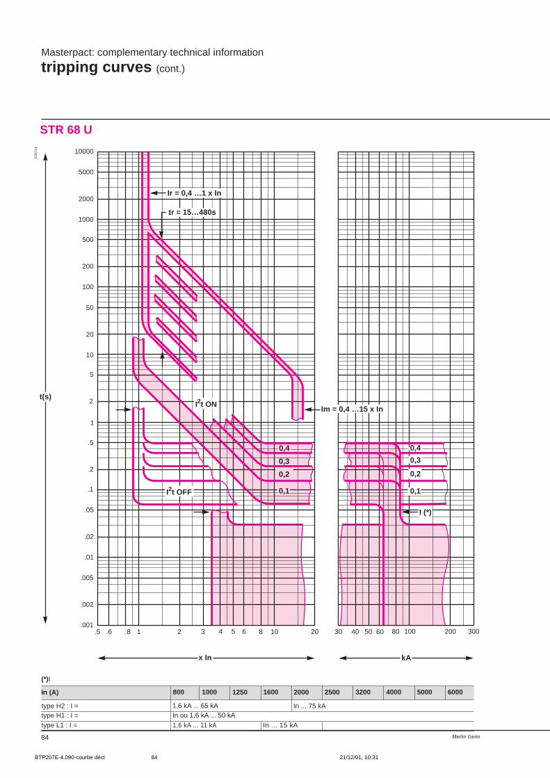
Merlin Gerin84
Masterpact: complementary technical information
tripping curves (cont.)
STR 68 U
.5 .6 .8 1 2 3 4 5 6 8 10 20 30 40 50 60 80 100 200 300.001
.002
.01
.02
.05
.1
.2
.5
.005
1
2
5
10
20
50
100
200
500
1000
2000
5000
10000
Ir = 0,4 …1 x In
tr = 15…480s
I2t ON
I2t OFF
I (*)
0,4
0,3
0,2
0,1 0,1
0,2
0,3
0,4
t(s)
x In kA
Im = 0,4 …15 x In
(*)I
In (A)
type H2 : I = 1,6 kA ... 65 kA
1000
type H1 : I =type L1 : I =
In ou 1,6 kA ... 50 kA
1,6 kA ... 11 kA
800 1250 1600 2000 2500 3200 4000 5000 6000
In ... 75 kA
In ... 15 kA
E30
714
BTP207E-4.090-courbe décl 21/12/01, 10:3184
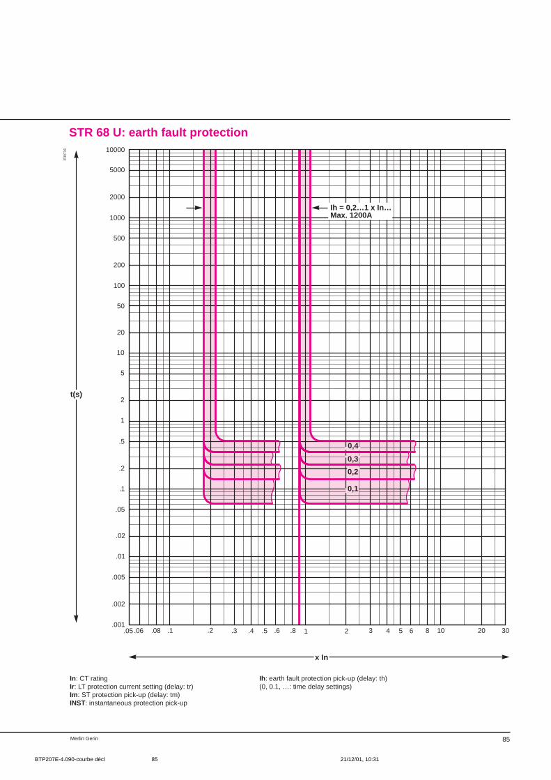
85Merlin Gerin
STR 68 U: earth fault protection
E30
716
.05 .06 .08 .1 .2 .3 .4 .5 .6 .8 1 2 3 4 5 6 8 10 20 30.001
.002
.01
.02
.05
.1
.2
.5
1
2
5
10
20
.005
50
100
200
500
1000
2000
5000
10000
0,1
Ih = 0,2…1 x In…Max. 1200A
0,4
0,3
0,2
t(s)
x In
In: CT ratingIr: LT protection current setting (delay: tr)Im: ST protection pick-up (delay: tm) INST: instantaneous protection pick-up
Ih: earth fault protection pick-up (delay: th)(0, 0.1, …: time delay settings)
BTP207E-4.090-courbe décl 21/12/01, 10:3185
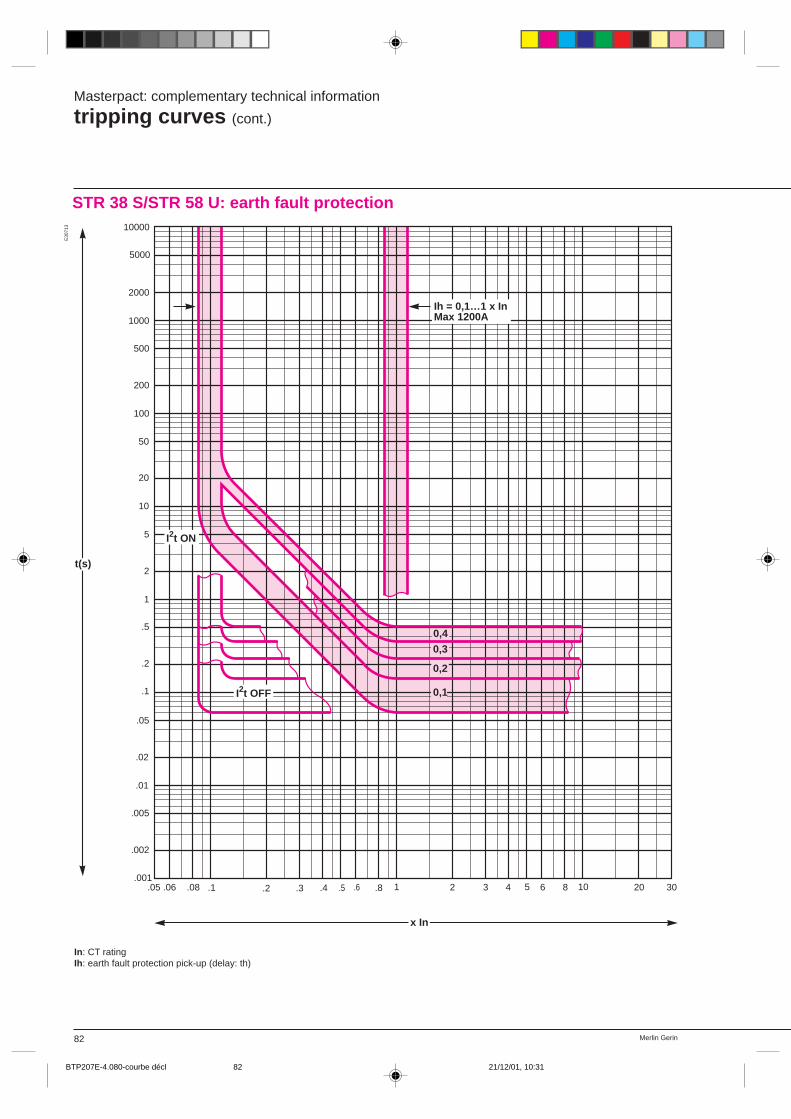
Merlin Gerin82
Masterpact: complementary technical information
tripping curves (cont.)
.05 .06 .08 .1 .2 .3 .4 .5 .6 .8 1 2 3 4 5 6 8 10 20 30.001
.002
.01
.02
.05
.1
.2
.5
1
2
5
10
20
.005
50
100
200
500
1000
2000
5000
10000
0,1
I2t ON
I2t OFF
Ih = 0,1…1 x InMax 1200A
0,2
0,30,4
t(s)
x In
In: CT ratingIh: earth fault protection pick-up (delay: th)
E30
713
STR 38 S/STR 58 U: earth fault protection
BTP207E-4.080-courbe décl 21/12/01, 10:3182
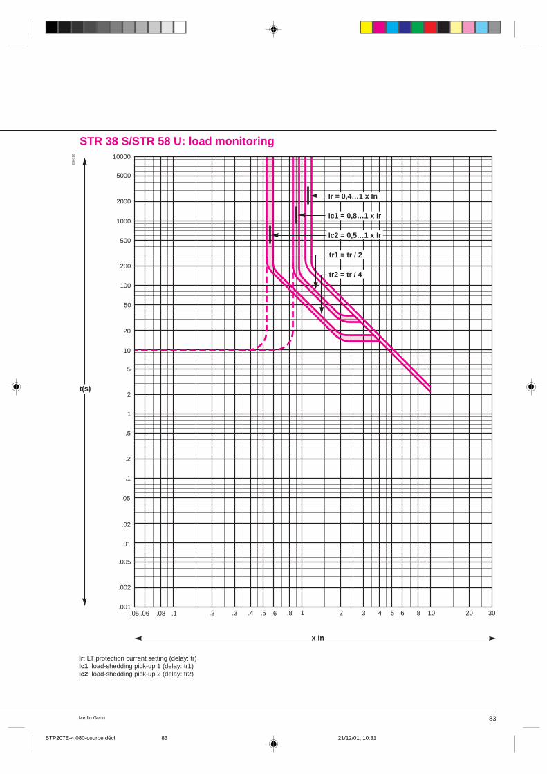
83Merlin Gerin
.05 .06 .08 .1 .2 .3 .4 .5 .6 .8 1 2 3 4 5 6 8 10 20 30.001
.002
.01
.02
.05
.1
.2
.5
1
2
5
10
20
.005
50
100
200
500
1000
2000
5000
10000
tr1 = tr / 2
Ir = 0,4…1 x In
Ic1 = 0,8…1 x Ir
Ic2 = 0,5…1 x Ir
tr2 = tr / 4
t(s)
x In
Ir: LT protection current setting (delay: tr)Ic1: load-shedding pick-up 1 (delay: tr1)Ic2: load-shedding pick-up 2 (delay: tr2)
E30
710
STR 38 S/STR 58 U: load monitoring
BTP207E-4.080-courbe décl 21/12/01, 10:3183
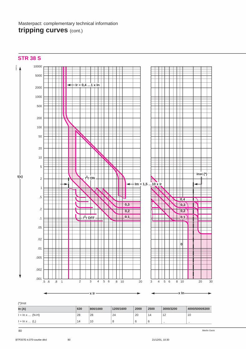
Merlin Gerin80
.5 .6 .8 1 2 3 4 5 6 8 10 20 3 4 5 6 8 10 20 30.001
.002
.01
.02
.05
.1
.2
.5
1
2
5
10
20
50
100
200
500
1000
2000
5000
10000
.005
0,3
0,2
0,1 0,1
0
Ir = 0,4 …1 x In
I2t ON
I2t OFF
Inst (*)
0,3
0,4
0,2
(*)Inst
In (A)
I = In x ... (N-H)
1200/1600 2000 2500 3000/3200 4000/5000/6300
I = In x ... (L)
800/1000
28 12
-
630
t(s)
x Ir x In
Im = 1,5 …10 x Ir
14
28
10
24
8
20
6
14
6
10
-
Masterpact: complementary technical information
tripping curves (cont.)
STR 38 S
E30
711
BTP207E-4.070-courbe décl 21/12/01, 10:3080

81Merlin Gerin
STR 58 U
.5 .6 .8 1 2 3 4 5 6 8 10 20 3 4 5 6 8 10 20 30.001
.002
.01
.02
.05
.1
.2
.5
1
2
5
10
20
50
100
200
500
1000
2000
5000
10000
.005
0,3
0,2
0,1
0,3
0,2
0,1
Ir = 0,4 …1 x In
tr = 15…480s
I2t ON
I = 2 x In…Max (*)
I2t OFF
0,4
0
(*)Max
In (A)
Max = In x ... (N-H)
Max = In x ... (L)
t(s)
x Ir x In
Im = 1,5 …10 x Ir
1200/1600800/1000
28
630
14
28
10
24
8
2000 2500 3000/3200 4000/5000/6300
12
-
20
6
14
6
10
-
E30
712
BTP207E-4.070-courbe décl 21/12/01, 10:3081
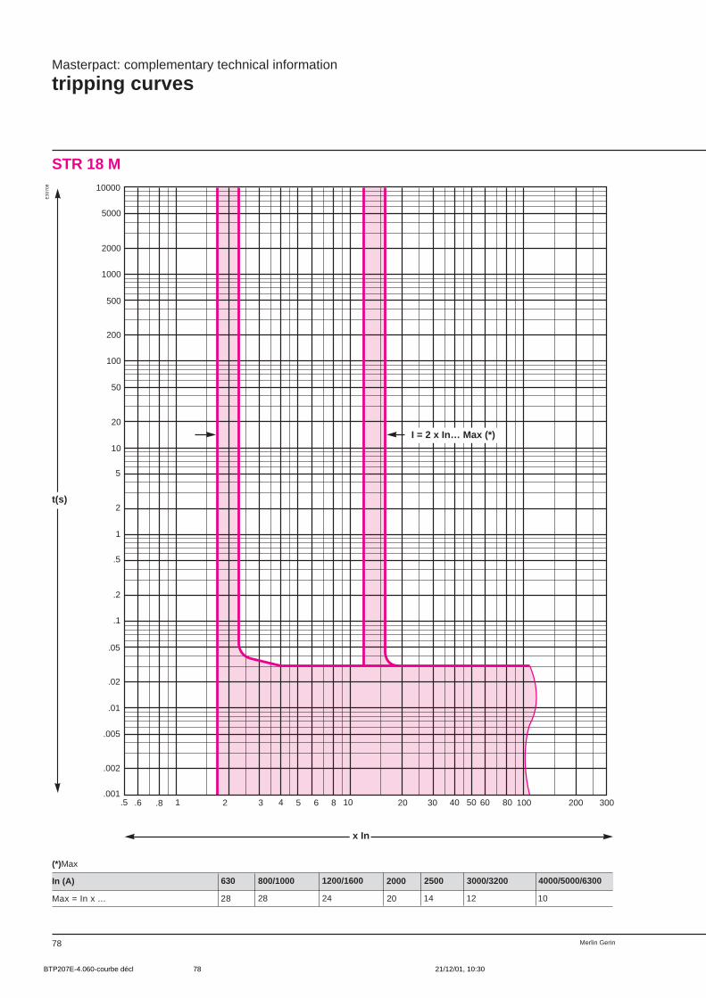
Merlin Gerin78
Masterpact: complementary technical information
tripping curves
STR 18 M
.5 .6 .8 1 2 3 4 5 6 8 10 20 30 50 100 200 300.001
.002
.01
.02
.05
.1
.2
.5
1
2
5
10
20
.005
50
100
200
500
1000
2000
5000
10000
I = 2 x In… Max (*)
40 60 80
(*)Max
In (A)
Max = In x ...
1200/1600 2000 2500 3000/3200 4000/5000/6300800/1000
28 28 24 20 14 12 10
630
t(s)
x In
E30
708
BTP207E-4.060-courbe décl 21/12/01, 10:3078

79Merlin Gerin
STR 28 D
.5 .6 .8 1 2 3 4 5 6 8 10 20 3 4 5 6 8 10 20 30.001
.002
.01
.02
.05
.1
.2
.5
1
2
5
10
20
50
100
200
500
1000
2000
5000
10000
.005
Ir = 0,4 …1 x In
Inst (*)
t(s)
x Ir x In
Im = 1,5 …10 x Ir
E30
709
Inst (*): fixed pick-up at 10 In
BTP207E-4.060-courbe décl 21/12/01, 10:3079

Merlin Gerin88
Masterpact: complementary technical information
effect of ambient temperature
ambient temperature The electrical and mechanicalcharacteristics are specified for an ambienttemperature between –5 and +60 °C.Masterpact circuit breakers operate from–10 and +70 °C.First closing minimum temperature: –30 °C.In addition, Masterpact circuit breakerscomply with IEC standards 68.2.1 and68.2.2: exceptional storage temperaturefrom: –50 to +100 °C.
Current rating (A) as a function ambient temperature ( °C)Masterpact M08N/H/L M10N/H/L M12N M12H M12L M16N/H M16L M20N/H M20L M25N/H M25L M32H M40H M50H M63Hversion connection T °Cdrawout front or rear 40 800 1 000 1 250 1 250 1 250 1 600 1 600 2 000 2 000 2 500 2 500 3 150 3 800 5 000 6 000
horizontal 45 800 1 000 1 250 1 250 1 250 1 600 1 600 2 000 2 000 2 500 2 350 3 080 3 650 4 750 5 70050 800 1 000 1 250 1 250 1 250 1 600 1 600 2 000 2 000 2 430 2 250 3 000 3 500 4 500 5 40055 800 1 000 1 250 1 250 1 250 1 600 1 600 2 000 2 000 2 350 2 150 2 900 3 300 4 250 5 10060 800 1 000 1 200 1 250 1 250 1 550 1 500 1 900 1 900 2 250 2 000 2 800 3 100 4 000 4 800
rear vertical 40 800 1 000 1 250 1 250 1 250 1 600 1 600 2 000 2 000 2 500 2 500 3 200 4 000 5 000 6 30045 800 1 000 1 250 1 250 1 250 1 600 1 600 2 000 2 000 2 500 2 500 3 200 3 800 5 000 6 00050 800 1 000 1 250 1 250 1 250 1 600 1 600 2 000 2 000 2 500 2 500 3 100 3 600 5 000 5 70055 800 1 000 1 250 1 250 1 250 1 600 1 600 2 000 2 000 2 500 2 350 3 000 3 400 5 000 5 40060 800 1 000 1 250 1 250 1 250 1 550 1 600 1 900 1 900 2 400 2 200 2 900 3 200 4 700 5 100
fixed front or rear 40 800 1 000 1 250 1 250 1 250 1 600 1 600 2 000 2 000 2 500 2 500 3 200 4 000 5 000 –horizontal 45 800 1 000 1 250 1 250 1 250 1 600 1 600 2 000 2 000 2 500 2 500 3 200 4 000 5 000 –
50 800 1 000 1 250 1 250 1 250 1 600 1 600 2 000 2 000 2 500 2 500 3 200 4 000 5 000 –55 800 1 000 1 250 1 250 1 250 1 600 1 600 2 000 2 000 2 500 2 500 3 200 3 900 5 000 –60 800 1 000 1 250 1 250 1 250 1 600 1 600 2 000 2 000 2 500 2 300 3 100 3 800 5 000 –
rear vertical 40 800 1 000 1 250 1 250 1 250 1 600 1 600 2 000 2 000 2 500 2 500 3 200 4 000 5 000 –45 800 1 000 1 250 1 250 1 250 1 600 1 600 2 000 2 000 2 500 2 500 3 200 4 000 5 000 –50 800 1 000 1 250 1 250 1 250 1 600 1 600 2 000 2 000 2 500 2 500 3 200 4 000 5 000 –55 800 1 000 1 250 1 250 1 250 1 600 1 600 2 000 2 000 2 500 2 500 3 200 4 000 5 000 –60 800 1 000 1 250 1 250 1 250 1 600 1 600 2 000 2 000 2 500 2 500 3 100 3 900 5 000 –
Power dissipation and resistance between inputs/outputspower(1) drawout 160 250 360 230 360 390 460 365 500 520 780 803 1 250 1 150 1 200dissipated (W) fixed 66 103 150 100 150 170 220 180 250 260 390 500 780 700 –input/output(2) drawout 53 53 53 32 50 32 31 18 23 17 23 15 15 9 9resistance (µΩ) fixed 33 33 33 16 36 16 12 9 10 8 10 10 10 8 –
(1) Values measured at In, 50/60 Hz for a 3-pole or 4-pole breaker.(2) Values measured per pole.
The table below indicates the maximumcurrent rating, for each connection type, as afunction of the ambient temperature aroundthe circuit breaker and the busbars.
BTP207E-4.110-déclassement 21/12/01, 10:3288

89Merlin Gerin
BTP207E-4.110-déclassement 21/12/01, 10:3289
Top Related