


Languages
Pages
Legal


PRIVATE RESIDENCE
ILLUMINATION LUSIN LIGHTING DESIGN | 2016
CONTENT
TASK
LIGHTING DESIGN
TECHNICAL
DOCUMENTATION
ARCHITECTURAL DESIGN. PLANS
INTERIOR LIGHTING
ARCHITECTURAL LIGHTING
EXTERIOR LIGHTING
RCPs
LIGHTING SPECIFICATION
LUSIN LIGHTING DESIGN 0800 860 6282

TASK
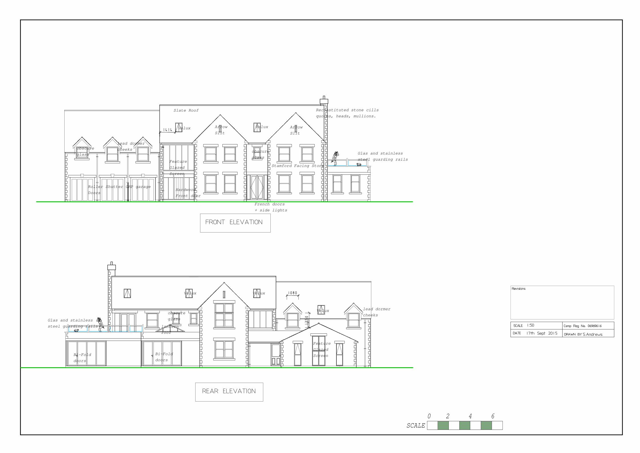
Hardwood
Front door
Roller Shutter GRP garage
Doors
lead dormer
cheeks
French doors
+ side lights
lead dormer
cheeks
Bi-Fold
doors
Bi-Fold
doors
lantern
roof
Slate Roof Reconstituted stone cills
quoins, heads, mullions.
Stamford Facing Stone
VeluxVelux
Velux Velux
Velux
Glas and stainless
steel guarding railsFeature
Glazed
Screen
obscure
glass
obscure
glass
Arrow
Slit
Arrow
Slit
Glas and stainless
steel guarding rails
Feature
Glazed
Screen
obscure
glass
SCALE
0 2 4 6

SCALE
0 2 4 6

Hardwood
Front door
Roller Shutter GRP garage
Doors
lead dormer
cheeks
French doors
+ side lights
lead dormer
cheeks
Bi-Fold
doors
Bi-Fold
doors
lantern
roof
Gravel Drive way
Slate Roof Reconstituted stone cills
quoins, heads, mullions.
Stamford Facing Stone
VeluxVelux
Velux Velux
Velux
Glas and stainless
steel guarding railsFeature
Glazed
Screen
obscure
glass
obscure
glass
Arrow
Slit
Arrow
Slit
Glas and stainless
steel guarding rails
Feature
Glazed
Screen
obscure
glass
Velux
SCALE
0 2 4 6

SCALE
0 2 4 6
Shower
change
Spices & prep
area
Boot
Room

w
En-Suite
En-Suite
w
En-Suite
down up
SCALE
0 2 4 6

Ground Floor Planning Approved 213sqm
First Floor Planning Approved 213sqm
Total 426sqm
Proposed Ground Floor Excluding Pool Area 262sqm.
Proposed First Floor 175sqm
Total 437sqm.
Existing buildings to be demolished ground covering 429Sqm.
SCALE
0 5 10 15
paddock area
and proposed
alotment
Shaded Areas Show Existing
Buildings To Be Removed.

SCALE
0 5 10 15
Walnut tree
Ash tree
new 1800mm high
Black Railings leading
to Post and rail
fence to be erected.
new 1800mm high
close boared timber
fence to be erected.
new stone wall to
match dwelling 750mm
high with black metal
railings
new electric gates
to be installed on stone peirs
1800mm high
gravel
drive
patio
area
patio
area
Yew
Tree
Pear
Apple
Plum
Cherry
Maple
MapleSycamore
SycamoreSycamore
Sycamore
Post and Rail
fence
Gravel access to
paddock and allotment
gates to paddock
Paddock area and Allotment area
Existing trees and
hedging to be
retained.
gate to
garden
gates to
garden
Existing Llylandii trees to be
removed and replaced with native
Blackthorn and Horn hedging, new
post and rail fence to be ereceted.
Post and rail
fence
Tarmac entrance
with acco drain
Willow Tree
existing land drain retained

Ground Floor Planning Approved 213sqm
First Floor Planning Approved 213sqm
Total 426sqm
Proposed Ground Floor Excluding Pool Area 262sqm.
Proposed First Floor 175sqm
Total 437sqm.
paddock area
and proposed
alotment
SCALE
0 5 10 15
Shaded Areas Show Existing
Planning approval 15/00259

SCALE 1250
SCALE
0 20 40 60
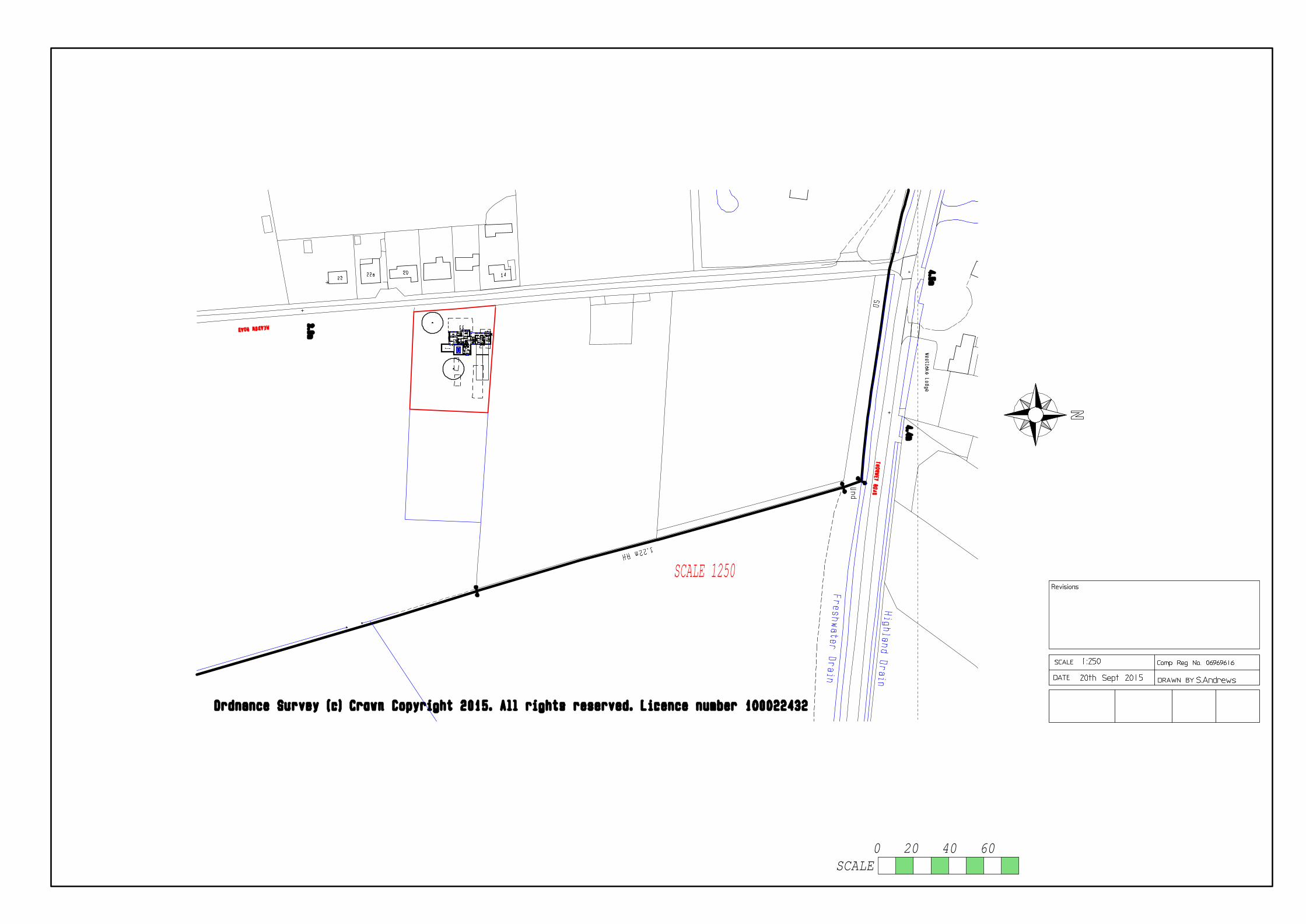
SCALE 1250w
En-Suite
En-Suite
w
En-Suite
downup
SCALE
0 20 40 60

LIGHTING DESIGN
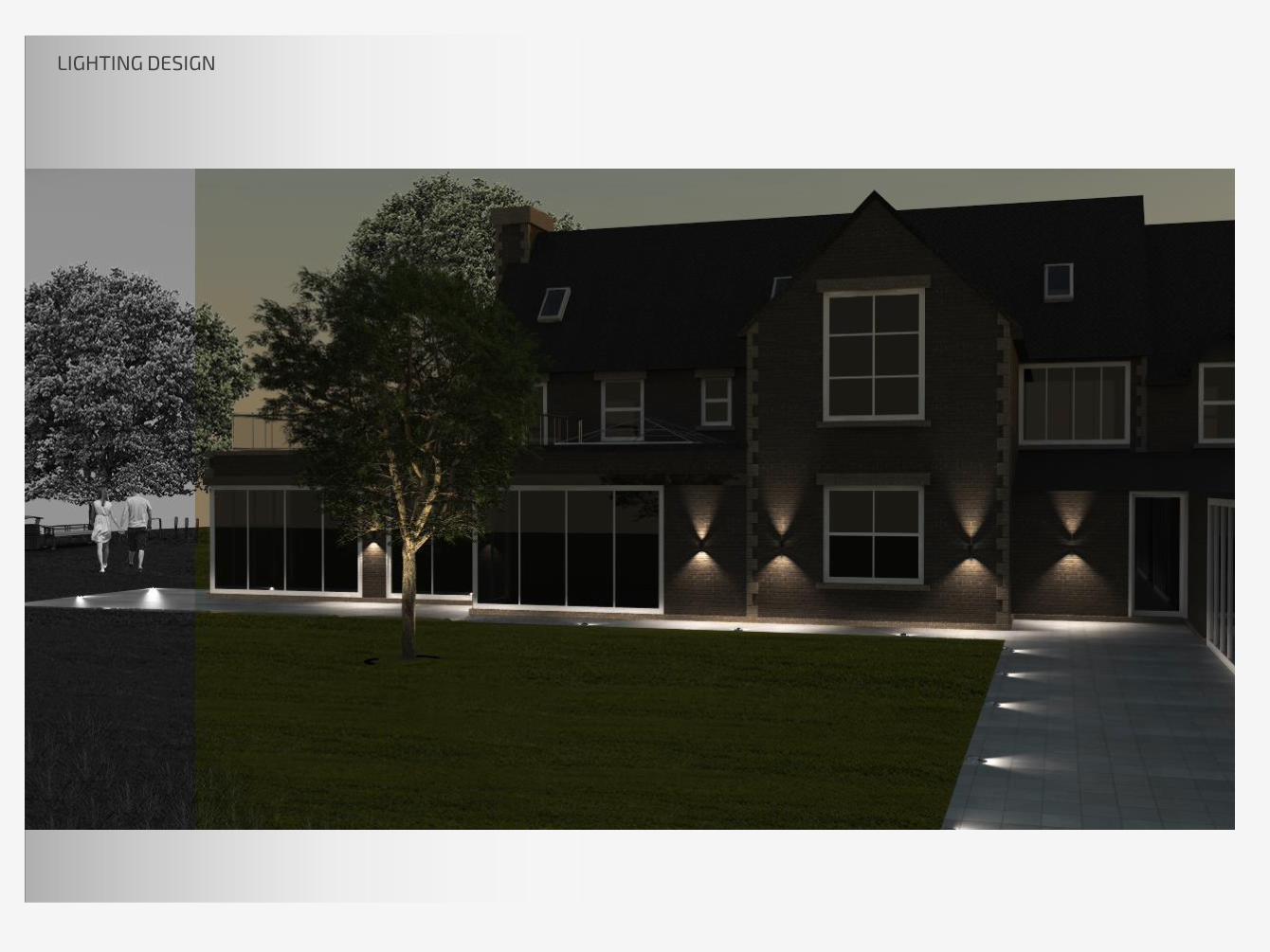
LIGHTING DESIGN

INTERIOR LIGHTING

INTERIOR LIGHTING DESIGN- ENTRANCE
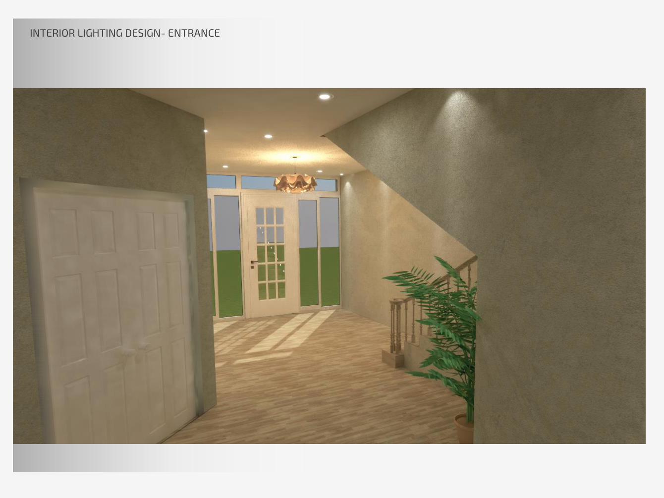
INTERIOR LIGHTING DESIGN- ENTRANCE

INTERIOR LIGHTING DESIGN – KITCHEN

INTERIOR LIGHTING DESIGN – DINNING ROOM

INTERIOR LIGHTING DESIGN – FAMILY ROOM

INTERIOR LIGHTING DESIGN – BILLIARD ROOM
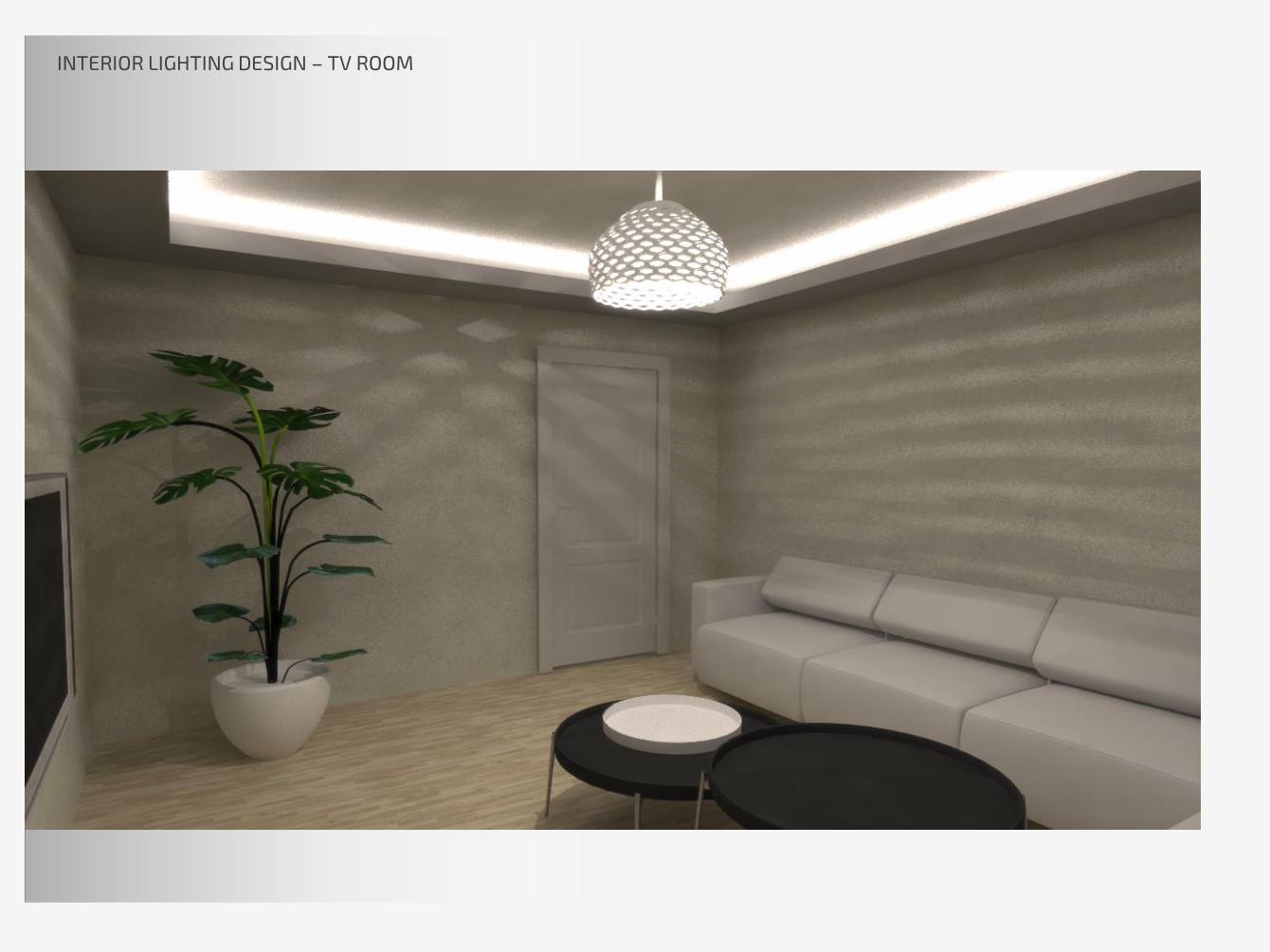
INTERIOR LIGHTING DESIGN – TV ROOM
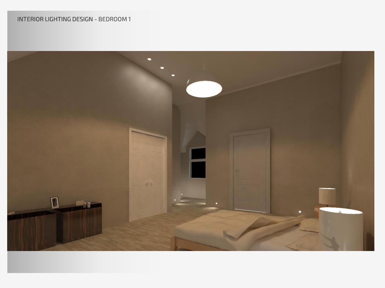
INTERIOR LIGHTING DESIGN INTERIOR LIGHTING DESIGN - BEDROOM 1

INTERIOR LIGHTING DESIGN INTERIOR LIGHTING DESIGN - BEDROOM 1
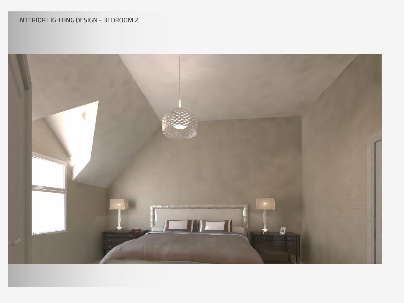
INTERIOR LIGHTING DESIGN INTERIOR LIGHTING DESIGN - BEDROOM 2
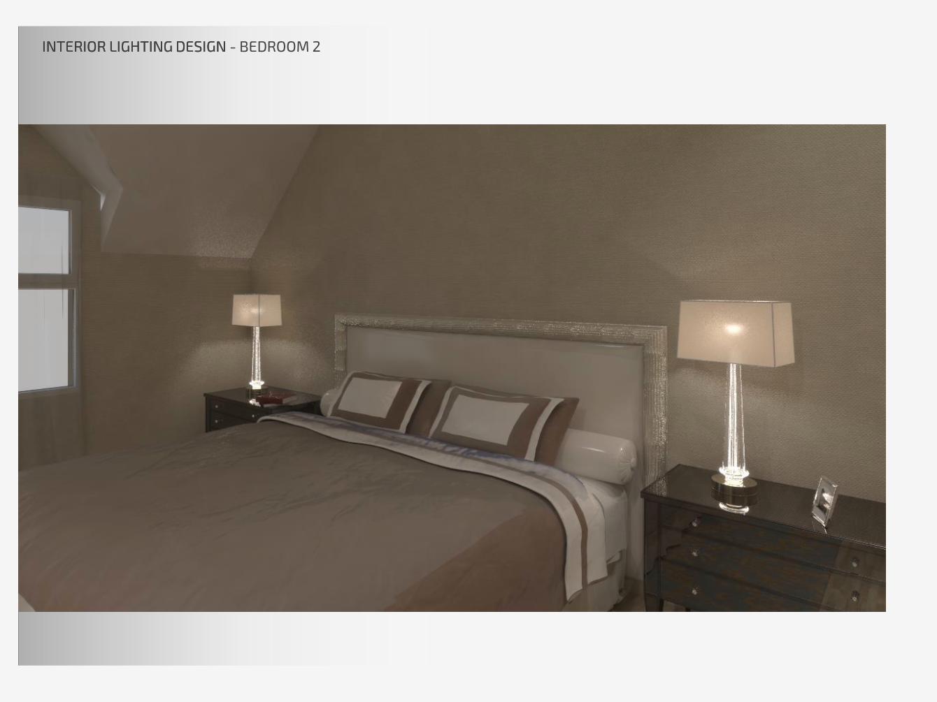
INTERIOR LIGHTING DESIGN INTERIOR LIGHTING DESIGN - BEDROOM 2

INTERIOR LIGHTING DESIGN - BEDROOM 2
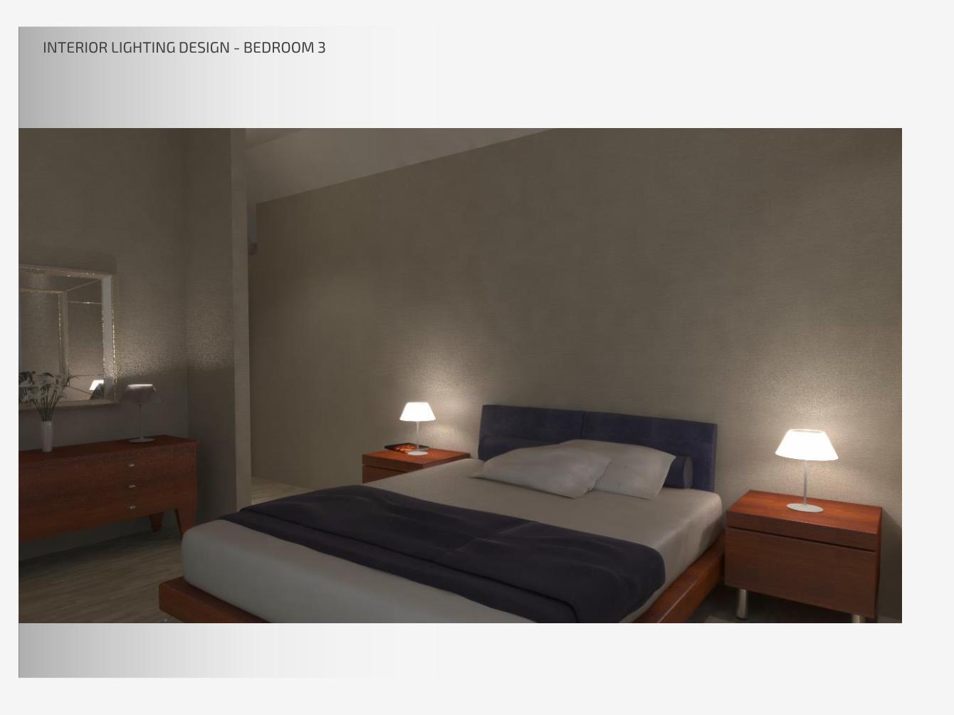
INTERIOR LIGHTING DESIGN - BEDROOM 3

INTERIOR LIGHTING DESIGN – BEDROOM 3

INTERIOR LIGHTING DESIGN – BEDROOM 4

INTERIOR LIGHTING DESIGN INTERIOR LIGHTING DESIGN - BATHROOM

INTERIOR LIGHTING DESIGN – POOL
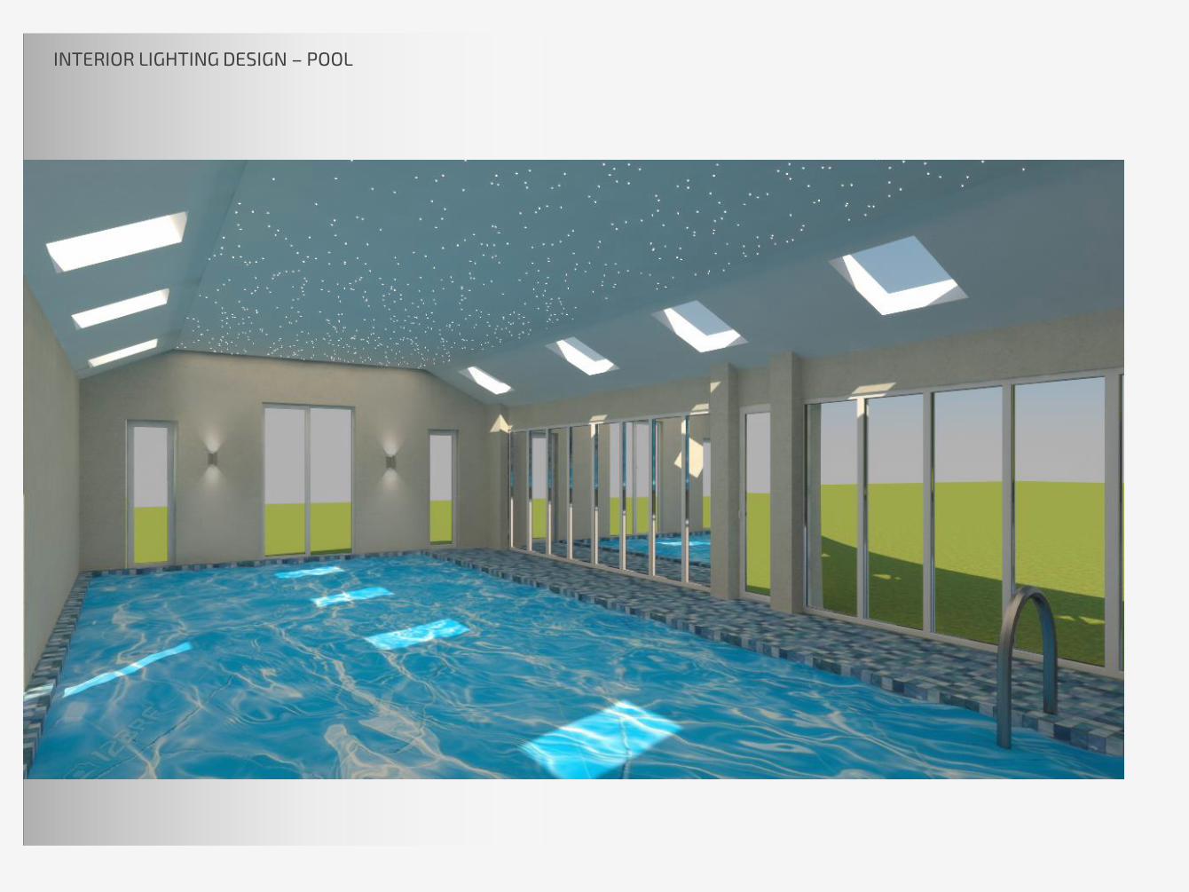
INTERIOR LIGHTING DESIGN – POOL

ARCHITECTURAL LIGHTING
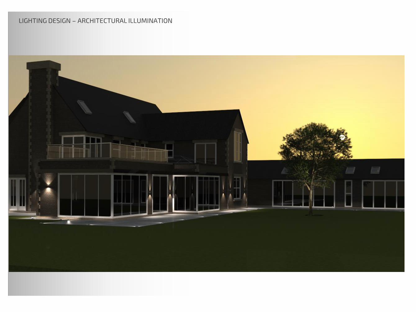
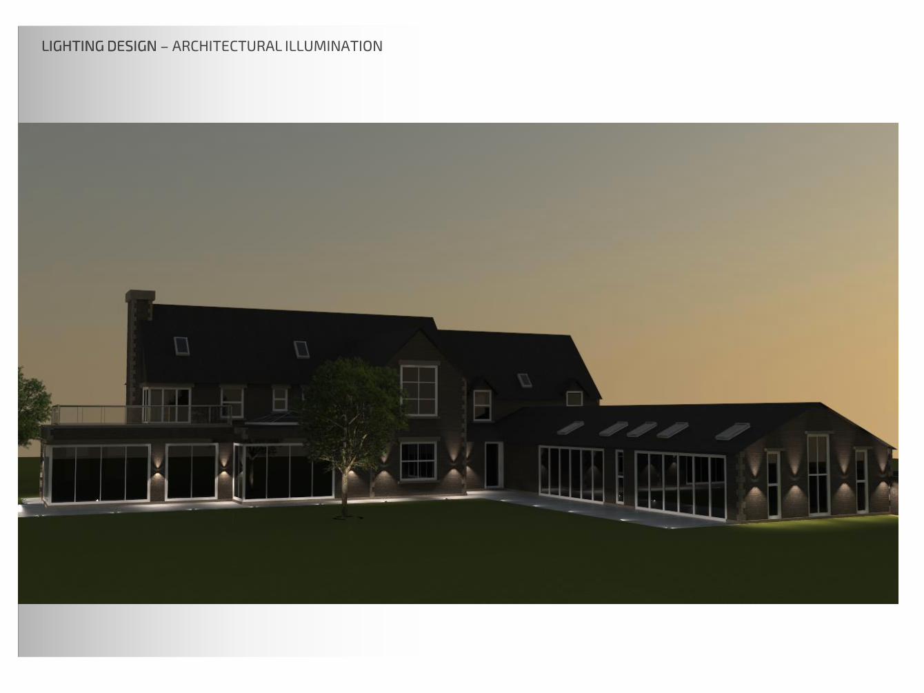
LIGHTING DESIGN – ARCHITECTURAL ILLUMINATION

LIGHTING DESIGN LIGHTING DESIGN – ARCHITECTURAL ILLUMINATION

LIGHTING DESIGN LIGHTING DESIGN – ARCHITECTURAL ILLUMINATION

LIGHTING DESIGN LIGHTING DESIGN – ARCHITECTURAL ILLUMINATION

LIGHTING DESIGN LIGHTING DESIGN – ARCHITECTURAL ILLUMINATION
LIGHTING DESIGN LIGHTING DESIGN – ARCHITECTURAL ILLUMINATION

EXTERIOR LIGHTING
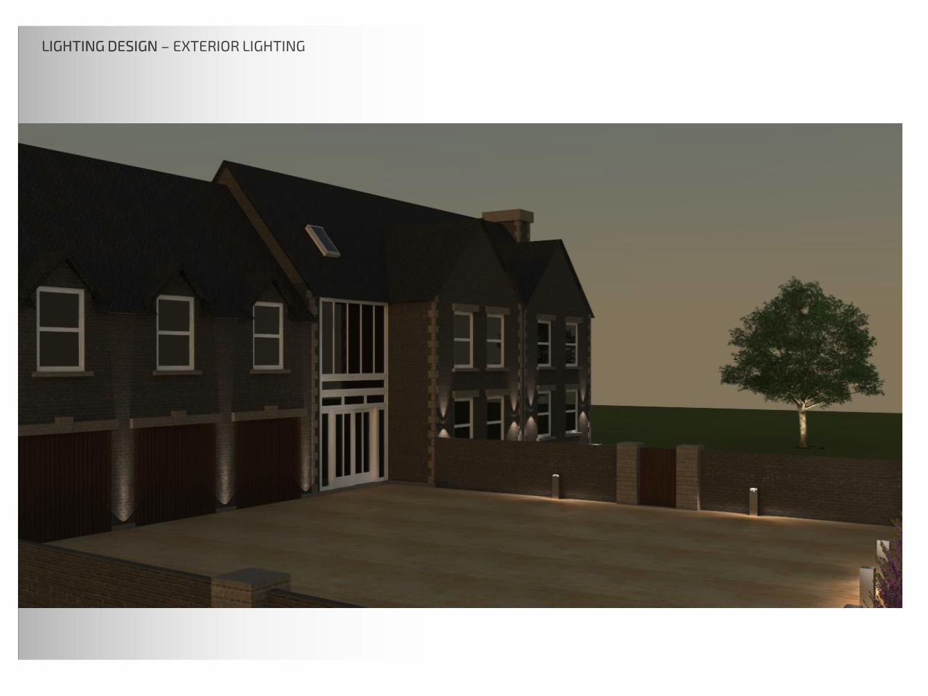
LIGHTING DESIGN LIGHTING DESIGN – EXTERIOR LIGHTING

TECHNICAL
DOCUMENTATION
SECURITY
IR
HU
B
IN
TE
RC
OM
PH
ON
E
INFRA-RED SENSOR FOR GARAGE DOORS
D
MOTION SENSOR
MOTION SENSOR
TERMOSTAT
SECURITY AND ALARM
LIGHT CONTROL
ENERGY MANAGEMENT
*
ENVIRONMENTAL MONITORING
GARAGE DOOR CONTROL
EXTERIOR LIGHTING CONTROL
WA
LL S
EN
SO
R P
AN
NE
L
EA
TH
ER
NE
T LA
YO
UT
Swimming pool
Shower
change
Porch
Boot
Room
TV Room
Dining
Family Room
open fire
Drawing Room
Garage
Porch
switch12
switch for pandant 2
socket for TV
mounting height determinedfrom the diagonal TV
socket
output for TV cabel
socket
switch 13
socket
switch for LED strip 1
socket
pass switch 6.2 (direction spot)
pass switch 6.1(direction spot)
socket
sw
itch for
star lights 14
double socket
waterproof
double socket
waterproof
Glazed Screen
pass sw
itch 4.2 (spot light)
pass sw
itch 3.2 (pandant lighting)
switch for LED strip 5
switch 3.1(pandant lighting)
pass switch 4.1 (spot light)
double waterproof
socket
double socket
for oven and
cooktop
(heat-resistant)
wire output for rangehood
switch for LED line
pass switch 7.2 (large pendant lighting)
pass switch 7.1(large pendant
lighting)
pass switch 8.1 (spot light)
pass switch 8.1 (spot light)
pass switch 9.2 (spot light)
pass switch 10.2 (direction spot)
pass switch 11.2 (pendan lighing)
pass switch 9.1 (spot light)
pass switch 10.1 (direction spot)
pass switch 11.1(pendan lighing)
double socket
double socket
double socket
double socket
double socket
WC
double socket
h = 900mm
h = 900mm
*height to specified
** * *
h = 900mm
h = 300mm
h = 300mm
h = 300mm
h = 1700mm
h = 900mm
h = 1000mm
h = 900mm
h =
9
00
mm
h =
3
00
mm
h =
3
00
mm
h = 900mm
h = 900mm
h = 300mmh = 900mm
h = 300mm
h = 300mm
h = 900mm
h = 900mm
h =
9
00
mm
sw
itch 19 (spot light)
socket
sw
itch 16
(spot light)
socket
sw
itch 12
(spot light)
double socket
sw
itch 21
(spot light)
sw
itch 15
(spot light)
sw
itch 10.1 (spot light)
sw
itch 11.1 (direction spot)
sw
itch 12.1 (pendant light)
switch 10.2 (spot light)
switch 11.2 (direction spot)
switch 12.2 (pendant light)
h = 900mm
h = 300mm
h =
9
00
mm
h =
9
00
mm
h =
9
00
mm
h =
9
00
mm
h =
9
00
mm
TVM intIR
intercom
phone
MOTION SENSOR
TERMOSTAT
SECURITY AND ALARM
HVAC CONTROL
LIGHT CONTROL
ENERGY MANAGEMENT
TV/VIDEO CONTROL
*
ENVIRONMENTAL MANITORING
TERRACE LIGHT CONTROL
EATHERNET LAYOUT
WALL SENSOR PANNEL
MUSIC CONTROL
RANGEHOOD ON/OFF CONTROL
security
REMOTE CONTROL
WALL SENSOR PANNEL
intercom
phone
MOTION SENSOR
TERMOSTAT
SECURITY AND ALARM
HVAC CONTROL
LIGHT CONTROL
ENERGY MANAGEMENT
TV/VIDEO CONTROL
*
ENVIRONMENTAL MANITORING
TERRACE LIGHT CONTROL
EATHERNET LAYOUT
MUSIC CONTROL
RANGEHOOD ON/OFF CONTROL
security
REMOTE CONTROL
WALL SENSOR PANNEL
D
MOTION SENSOR
MOTION SENSOR
TERMOSTAT
SECURITY AND ALARM
HVAC CONTROL
LIGHT CONTROL
ENERGY MANAGEMENT
TV/VIDEO CONTROL
*
ENVIRONMENTAL MANITORING
TERRACE LIGHT CONTROL
MUSIC CONTROL
RANGEHOOD ON/OFF CONTROL
WALL SENSOR PANNEL
REMOTE CONTROL
TVM intIR
TVM intIR
MOTION SENSOR
TERMOSTAT
SECURITY AND ALARM
HVAC CONTROL
LIGHT CONTROL
ENERGY MANAGEMENT
TV/VIDEO CONTROL
*
ENVIRONMENTAL MANITORING
TERRACE LIGHT CONTROL
MUSIC CONTROL
RANGEHOOD ON/OFF CONTROL
MOTION SENSOR
TERMOSTAT
SECURITY AND ALARM
HVAC CONTROL
LIGHT CONTROL
ENERGY MANAGEMENT
TV/VIDEO CONTROL
*
ENVIRONMENTAL MANITORING
TERRACE LIGHT CONTROL
MUSIC CONTROL
RANGEHOOD ON/OFF CONTROL
intercom
phone
security
intercom
phone
security
MOTION SENSOR
TERMOSTAT
SECURITY AND ALARM
HVAC CONTROL
LIGHT CONTROL
ENERGY MANAGEMENT
TV/VIDEO CONTROL
*
ENVIRONMENTAL MANITORING
TERRACE LIGHT CONTROL
MUSIC CONTROL
RANGEHOOD ON/OFF CONTROL
WA
LL S
EN
SO
R P
AN
NE
L
REMOTE CONTROL
MOTION SENSOR
LIGHT CONTROL
AIR/VENT CONTROL
VENT FAN CONTROL
REMOTE CONTROL
IR
MOTION SENSOR
LIGHT CONTROL
AIR/VENT CONTROL
VENT FAN CONTROL
REMOTE CONTROL
IR
PROJECT
CLIENT
TITLE
DATEDESIGNED
REV
SIZESCALE
PROJECT No
CHECKED
DRG No
Rev. Description Drn. Check.Date
This calculation is based upon specified
parameters supplied by the client, and other
assumed design inputs, as detailed in this
document. In practice, there may be variations
due to differences in as-installed luminaire
positioning, room surface reflectance, supply
voltage, photometric tolerances, etc, & normally
accepted uncertainties. We reserve the right to
modify the scheme if relevant information
subsequently becomes available.
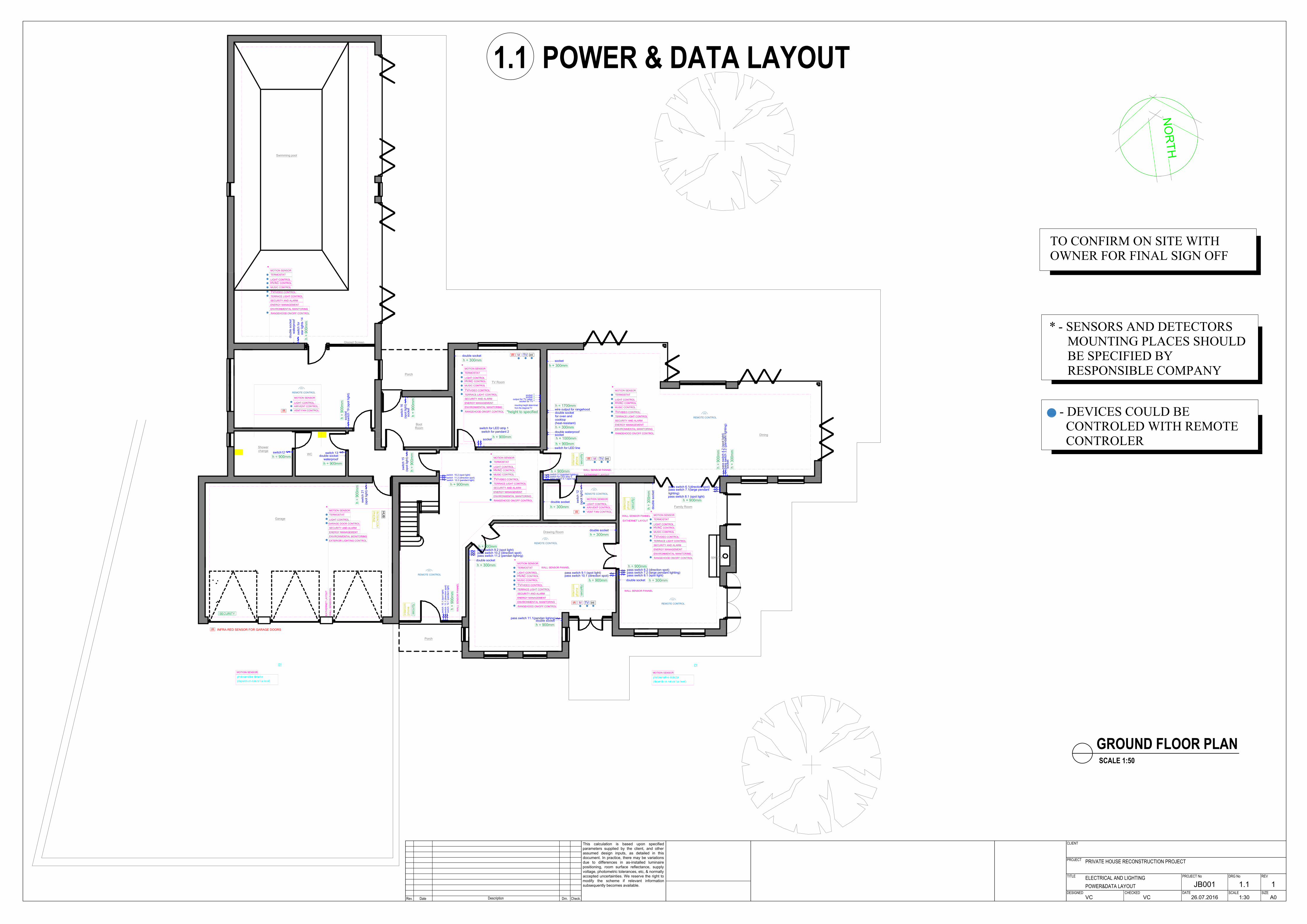
PRIVATE HOUSE RECONSTRUCTION PROJECT
ELECTRICAL AND LIGHTINGPOWER&DATA LAYOUT JB001 1.1 1
VC VC 26.07.2016 1:30 A0
GROUND FLOOR PLANSCALE 1:50
TO CONFIRM ON SITE WITHOWNER FOR FINAL SIGN OFF
1.1 POWER & DATA LAYOUT
photosensitive detector(depends on natural lux level)
photosensitive detector(depends on natural lux level)
* - SENSORS AND DETECTORSMOUNTING PLACES SHOULDBE SPECIFIED BYRESPONSIBLE COMPANY
- DEVICES COULD BE CONTROLED WITH REMOTE CONTROLER
w
w
En - Suite 1
Bedroom 1
En - Suite 3
En - Suite 4
En - Suite 2
Bedroom 2
Bedroom 3
Bedroom 4
pass switch 22
( En -suite 2)
socket
double socket
double socket
double socket
double socket
double socket
double socket
do
ub
le
so
cke
t
do
ub
le
so
cke
t
switch 28 (spot lights)
switch 29 (pendan lighing)
double socket
double socket
sw
itch
2
1 (sm
oll sp
ots)
sw
itch
2
2d
ire
ctio
n sp
ots)
sw
itch
2
3(p
en
da
n lig
hin
g)
switch 16 (pendan lighing)
switch 17 (smoll spots)
sw
itch
2
6
double socket
En - Suite
Dressing
room
Balconey
Laundry
Room
Dressing
room
Gallery Landing
down
up
sw
itch
1
8
( E
n -su
ite
1)
sw
itch
1
9
(d
ire
ctio
n sp
ots)
double socket
h = 900mm
h = 900mm
h = 900mm
h = 900mm
h = 900mm
h = 900mm
h = 900mm
h = 900mm
h =
9
00
mm
h =
9
00
mm
h = 300mm
h =
9
00
mm
h = 900mm
h = 300mm
do
ub
le
so
cke
t
h =
3
00
mm
h = 900mm
h =
9
00
mm
h =
9
00
mm
h = 725mm
switch for mechanical
ventilation
socket waterproof
switch for
mechanical
ventilation
socket waterproof
switch for mechanical
ventilation
socket waterproof
switch for
mechanical
ventilation
socket waterproof
h = 725mm
h = 725mm
double socket
h = 900mm
switch 30 (small spots)
h = 900mm
h =
9
00
mm
sw
itch
3
1
( E
n -su
ite
1)
h = 300mm
sw
itch
2
5(p
en
da
n lig
hin
g)
sw
itch
2
4(sm
all sp
ots)
h =
90
0m
m
do
ub
le
sw
itch
2
0.1
h =
9
00
mm
do
ub
le
sw
itch
2
0.2
h =
90
0m
m
sw
itch
2
7
h =
9
00
mm
sw
itch
3
1
(sp
ot lig
hts)
h =
9
00
mm
sw
itch
3
1
(sp
ot lig
hts)
h = 900mm
switch 31
(spot lights)switch for
mechanical
ventilation
socket
waterproof
h = 725mm
double socket
h = 300mm
double socket
h = 300mm
double socket
h = 750mm
sw
itch
4
4
h =
9
00
mm
MOTION SENSOR
TERMOSTAT
SECURITY AND ALARM
LIGHT CONTROL
ENERGY MANAGEMENT
ENVIRONMENTAL MONITORING
*
WA
LL
S
EN
SO
R P
AN
NE
L
EA
TH
ER
NE
T L
AY
OU
T
REMOTE CONTROL
MOTION SENSOR
TERMOSTAT
SECURITY AND ALARM
LIGHT CONTROL
ENERGY MANAGEMENT
ENVIRONMENTAL MONITORING
*
WA
LL
S
EN
SO
R P
AN
NE
L
EA
TH
ER
NE
T L
AY
OU
T
MOTION SENSOR
TERMOSTAT
SECURITY AND ALARM
LIGHT CONTROL
ENERGY MANAGEMENT
ENVIRONMENTAL MONITORING
*
WA
LL
S
EN
SO
R P
AN
NE
L
EA
TH
ER
NE
T L
AY
OU
T
intercom
phone
REMOTE CONTROL
intercom
phone
REMOTE CONTROL
MOTION SENSOR
TERMOSTAT
SECURITY AND ALARM
LIGHT CONTROL
ENERGY MANAGEMENT
ENVIRONMENTAL MONITORING
*
WALL SENSOR PANNEL
EATHERNET LAYOUT
intercom
phone
REMOTE CONTROL
MOTION SENSOR
LIGHT CONTROL
AIR/VENT CONTROL
VENT FAN CONTROL
IR
REMOTE CONTROL
MOTION SENSOR
TERMOSTAT
SECURITY AND ALARM
LIGHT CONTROL
ENERGY MANAGEMENT
ENVIRONMENTAL MONITORING
*
REMOTE CONTROL
MOTION SENSOR
LIGHT CONTROL
AIR/VENT CONTROL
VENT FAN CONTROL
REMOTE CONTROL
IR
PROJECT
CLIENT
TITLE
DATEDESIGNED
REV
SIZESCALE
PROJECT No
CHECKED
DRG No
Rev. Description Drn. Check.Date
This calculation is based upon specified
parameters supplied by the client, and other
assumed design inputs, as detailed in this
document. In practice, there may be variations
due to differences in as-installed luminaire
positioning, room surface reflectance, supply
voltage, photometric tolerances, etc, & normally
accepted uncertainties. We reserve the right to
modify the scheme if relevant information
subsequently becomes available.
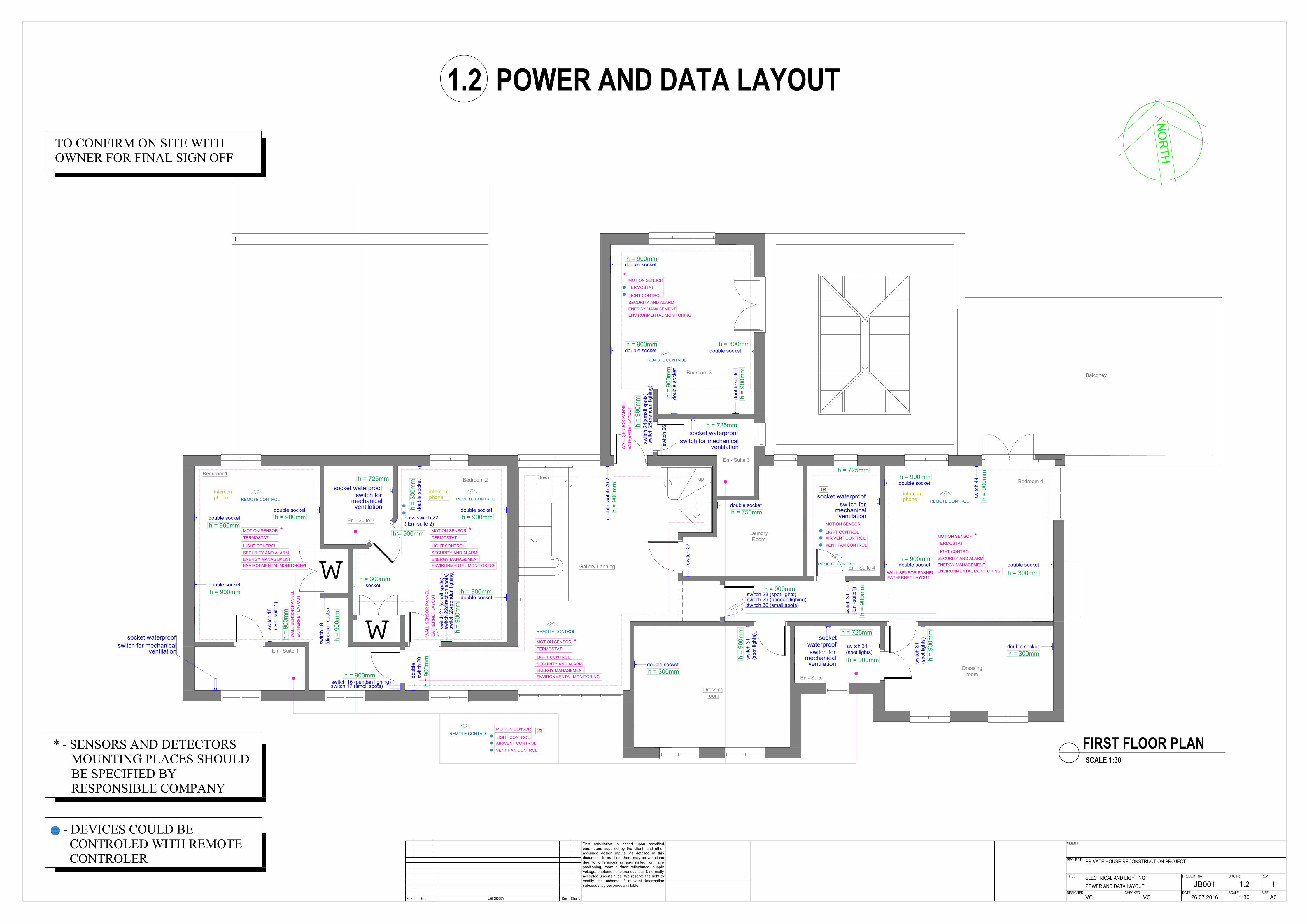
PRIVATE HOUSE RECONSTRUCTION PROJECT
ELECTRICAL AND LIGHTINGPOWER AND DATA LAYOUT JB001 1.2 1
VC VC 26.07.2016 1:30 A0
1.2 POWER AND DATA LAYOUT
FIRST FLOOR PLANSCALE 1:30
TO CONFIRM ON SITE WITHOWNER FOR FINAL SIGN OFF
* - SENSORS AND DETECTORSMOUNTING PLACES SHOULDBE SPECIFIED BYRESPONSIBLE COMPANY
- DEVICES COULD BE CONTROLED WITH REMOTE CONTROLER

Swimming pool
Shower
change
Porch
Boot
Room
TV Room
Kitchen
Dining
Family Room
open fire
Drawing Room
Spices & prep
area
Garage
Porch
switch12
sw
itch for pandant 2
socket for TV
mounting height determinedfrom the diagonal TV
socket
output for TV cabel
socket
switch 13
socket
sw
itch for LE
D strip 1
socket
pass switch 6.2
pass switch 6.1
socket
sw
itch for
star lights 14
double socket
waterproof
double socket
waterproof
Glazed Screen
pass sw
itch 4.2
pass sw
itch for pandant 3.2
switch for LED strip 5
switch for pandant 3.1
pass switch 4.1
double waterproof
socket
double socket
for oven and
cooktop
(heat-resistant)
wire output for rangehood
LE
D line
switch for LED line
pass switch 7.2
pass switch 7.1
pass switch 8.1
pass switch 8.1
pass switch 9.2
pass switch 10.2
pass switch 11.2
pass switch 9.1
pass switch 10.1
pass switch 11.1
double socket
double socket
double socket
double socket
double socket
WC
S
double socket
LED STRIP ALONG
THE PERIMETRE
LED STRIP ALONG
THE PERIMETRE
ST1 ST1ST1 ST1
ST2
ST2 ST2
ST2 ST2 ST2
ST2
ST2
ST2
ST2
G1 G1 G1
ST3
ST3
ST3
ST3
ST3 ST3 ST3 ST3
ST3
ST3 ST3
ST3
ST3
ST3 ST3
ST3
ST3
ST3
ST3
ST3 ST3 ST3 ST3 ST3 ST3 ST3 ST3
ST3
ST3
ST3
ST3
ST3
ST4
ST4
ST4
ST4
OUTPUT FOR FASADE ILLUMINATIONST5
ST5 ST5 ST5 ST5
ST5
ST5 ST5 ST5
ST5 ST5
ST5ST5
ST5
ST5
ST5
ST5ST5
ST5ST5
S1
S1
S1
S1
S1
S1 S1
S1
switch 12
switch 10.2 (spot light)
switch 11.2 (direction spot)
switch 12.2 (pendant light)
sw
itch for exterior light S
T1+
fasades
double socket
waterproof
sw
itch for exterior light S
T2
sw
itch for exterior light S
T3 +
S
T4
switch 21
(strip light)
switch 16
S1
S1S1
S1
S1 S1
S1S1
S1
S1
S1
S1
S1
S1
S1
S1
S1
S1
S1
D
D
D
D
D
D
D
D
DD D
DD
D
D
DD D
DD D
D
D
D
D
D
D
D
D
D
D
D
D
D D
D
D
D
D
S1
S1
S1
S1
S1
S1
S1
S1
S1 S1
S1S1
P1
P1
P1
P1 P1 P1
S1 S1 S1
S1 S1 S1
S1 S1 S1
S1 S1
switch 10.1 (spot light)
switch 11.1 (direction spot)
switch 12.1 (pendant light)
P2
S1 S1 S1
S1 S1 S1
S1 S1 S1
S1 S1 S1
S1 S1
S1 S1S1
S1
S1
S1 S1 S1
S1
D
double socket
double socket
double socket
S1 S1S1
S1
switch 15
S1 S1
S1S1
S1 S1
S1S1
P1
P2
W
W
W
W
W
W
sw
itch for star lights 14.1
PROJECT
CLIENT
TITLE
DATEDESIGNED
REV
SIZESCALE
PROJECT No
CHECKED
DRG No
Rev. Description Drn. Check.Date
This calculation is based upon specified
parameters supplied by the client, and other
assumed design inputs, as detailed in this
document. In practice, there may be variations
due to differences in as-installed luminaire
positioning, room surface reflectance, supply
voltage, photometric tolerances, etc, & normally
accepted uncertainties. We reserve the right to
modify the scheme if relevant information
subsequently becomes available.
PRIVATE HOUSE RECONSTRUCTION PROJECT
ELECTRICAL AND LIGHTINGLIGHTING CIRCUITS JB001 1.3 1
VC VC 26.07.2016 1:50 A0
GROUND FLOOR PLANSCALE 1:50
TO CONFIRM ON SITE WITHOWNER FOR FINAL SIGN OFF
1.3 ELECTRICAL LAYOUT. LIGHTING CIRCUITS
En - Suite 1
Bedroom 1
En - Suite 3
En - Suite 4
En - Suite 2
Bedroom 2
Bedroom 3
Bedroom 4
p
a
s
s
s
w
i
t
c
h
2
2
socket
double socket
double socket
double socket
double socket
double socket
double socket
do
ub
le
so
cke
t
do
ub
le
so
cke
t
switch 26
switch 27
T4
T4
T3
T3
T2
T2T1
T1 double socket
double socket
sw
itch
2
0
sw
itch
2
1
sw
itch
2
1
switch 16
switch 17
T3 T3
sw
itch
2
5
socket
En - Suite
Dressing
room
Balconey
Laundry
Room
Dressing
room
Gallery Landing
down
up
sw
itch
1
8
sw
itch
1
9
double socket
do
ub
le
so
cke
t
switch for mechanical
ventilation
socket waterproof
switch for mechanical
ventilation
socket waterproof
switch for mechanical
ventilation
socket waterproof
switch for mechanical
ventilation
socket waterproof
double socket
switch 28
sw
itch
2
9
switch 24(pendan lighing)
switch 23(small spots)
w
w
double switch 20.1
double switch 20.2
sw
itch
2
7
switch 31(spot lights)
switch 31 (spot lights)
switch 31
(spot lights)
switch for
mechanical
ventilation
socket
waterproof
double socket
double socket
double socket
S2 S2
S2 S2S2
S2S2 S2
S2
S2
S2 S2
D1 D1 D1
D1
D1
D1
P1P1
P1
P1
S2S2
S2
S2
S2
S2
S2
S2
S2
S2
S2 S2
S2S2
S1 S1 S1
S1 S1
S1S1
S1
S1
S1
S1 S1
S1
S1
S1 S1
S1
S1
S1S1S1
S1
S1
S1
S1
S1
S1
S1
S1
S1
S1
S1
S1
S1
S1
S1
S1
S1 S1 S1
S1
S1S1
S1S1
S1S1S1
S1S1S1
S2 S2 S2S2
S2
S2S2S2S2S2S2S2S2S2S2
S2S2
S2 S2 S2 S2S2 S2 S2
S2 S2 S2 S2
S2
S2
S2
S2
S2S2S2S2
S2
S2S2 S2
S2 S2 S2
S2 S2 S2 S2
S2 S2
S2
S2
S2S2S2S2
S2
S2 S2
sw
itch
4
4
LED line - floor recessed items
PROJECT
CLIENT
TITLE
DATEDESIGNED
REV
SIZESCALE
PROJECT No
CHECKED
DRG No
Rev. Description Drn. Check.Date
This calculation is based upon specified
parameters supplied by the client, and other
assumed design inputs, as detailed in this
document. In practice, there may be variations
due to differences in as-installed luminaire
positioning, room surface reflectance, supply
voltage, photometric tolerances, etc, & normally
accepted uncertainties. We reserve the right to
modify the scheme if relevant information
subsequently becomes available.
PRIVATE HOUSE RECONSTRUCTION PROJECT
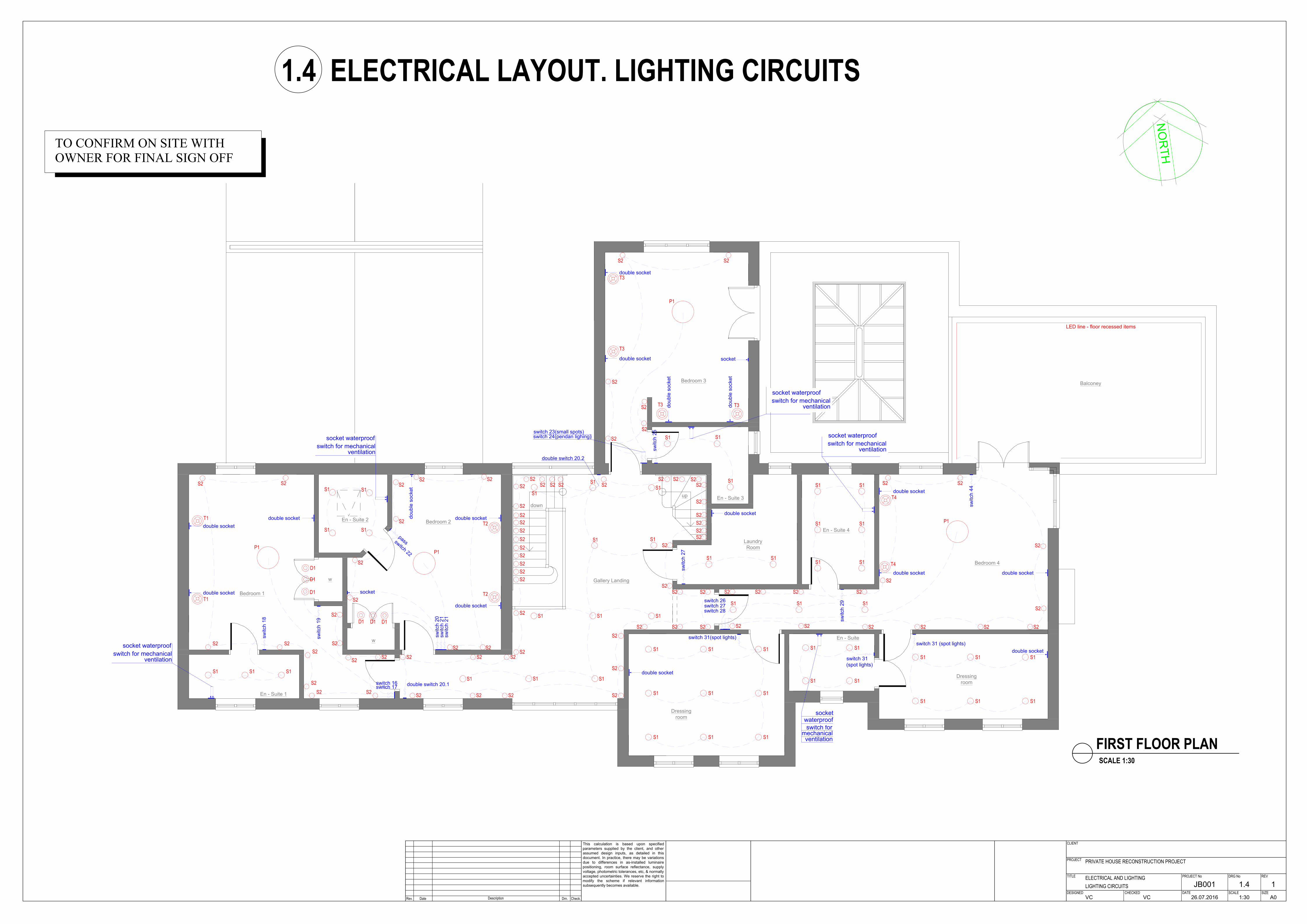
ELECTRICAL AND LIGHTINGLIGHTING CIRCUITS JB001 1.4 1
VC VC 26.07.2016 1:30 A0
FIRST FLOOR PLANSCALE 1:30
1.4 ELECTRICAL LAYOUT. LIGHTING CIRCUITS
TO CONFIRM ON SITE WITHOWNER FOR FINAL SIGN OFF
Swimming pool
Shower
change
Porch
Boot
Room
TV Room
Kitchen
Dining
Family Room
open fire
Drawing Room
Spices & prep
area
Garage
Porch
switch18
(spot light)
sw
itch 14 for pandant 2
socket for TV
mounting height determinedfrom the diagonal TV
socket
output for TV cabel
socket
switch 17
(spot light)
sw
itch 13 for LE
D strip 1
Glazed Screen
switch 4.2
switch for pandant 3.2
switch for LED strip 5
switch for LED line
double socket
WC
pass switcher 20 for star lights
S1 output
S1 output
S1 output
S1 output
S1 output
S1 output
S1 output
S1 output
lighting line 1
lighting line 3
lighting line 3
lighting line3
lighting line 3
P2 output
sw
itch 22 for exterior light S
T1+
fasades
double socket
waterproof
sw
itch 23 for exterior light S
T2
sw
itch 24 for exterior light S
T3 +
S
T4
output in the wall for LED line -
2.1-2.15m from floor level
G1 output G1 output G1 output
T1 output T1 output T1 output T1 output
ST2 output
ST2 output
ST2 output
ST2 output
ST2 output
ST2 output ST2 output
ST2 output
ST2 output
ST2 output
ST4 outputST4 output
ST4 outputST4 output
ST4 output
ST4 output
ST4 outputST4 output
ST4 output
ST4 output
ST4 output
ST4 outputST4 output
ST4 output
ST4 output
ST4 outputST4 output
ST4 outputST4 output
ST3 output
ST3 output
ST3 output
ST3 output
ST3 output ST3 output ST3 output
ST3 output
ST3 output
ST3 output
ST3 output
ST3 output
ST3 outputST3 outputST3 outputST3 outputST3 outputST3 outputST3 outputST3 output
ST3
output
ST3
output
ST3
output
ST3
output
ST3
output
ST3
output
ST3
output
ST3
output
ST3
output
ST3
output
ST3
output
ST3
output
lighting line 4
lighting line 4
lighting line 4
switch 19 for spot light
lighting line 2
lighting line 2
S1 output
S1 output
S1 outputS1 output
S1 output
S1 outputS1 output
S1 output
S1
output
S1
output
S1
output
S1
output
P2 output
lighting line7
lighting line 5
lighting line 6
S1
output
S1
output
S1
output
S1
output
lighting line 8
lighting line10
pass switch 9.2 (spot light)
pass switch 10.2 (direction spot)
pass switch 11.2 (pendant lighing)
pass switch 9.1 (spot light)
pass switch 10.1 (direction spot)
pass switch 11.1
(pendant lighing)
double socket
S1 output
S1 output
S1 output
S1 output
S1 output
S1 output
S1 output
S1
output
S1
output
S1
output
S1
output
S1
output
P2
output
P2
output
P2
output
D output
D output
D output
D output
D output
D output
D
output
D output
D output
D output
D output
D output
D
output
D
output
D
output
D
output
D
output
D outputD output
D
output
D
output
D outputD outputD output
D
output
D
output
D output
S1
output
S1
output
S1
output
S1
output
S1
output
S1
output
S1
output
S1
output
S1 outputS1 outputS1 output
S1 outputS1 outputS1 output
S1 output
S1
output
S1
output
S1
output
S1
output
S1 output
S1 outputS1 output
S1 output
S1 output S1 output
S1 output
S1 output S1 output S1 output
S1 output
S1 output
S1 outputS1 outputS1 outputS1 output
S1 output
S1 output
P1 output
P2 output
P2 output P2 output
S1 output
S1 output
S1 output
S1 outputS1 output
S1 output S1 outputS1 output
S1 outputS1 output
S1 output
D output
D output
D output
D output
D output
D output
D output
D output
D output
D
output
D
output
D
output
pass switch 6.2 (direction spot)
pass switch 6.1(direction spot)
pass switch 7.2 (large pendant lighting)
pass switch 7.1(large pendant )
pass switch 8.1 (spot light)
pass switch 8.1 (spot light)
output in the w
all for LE
D line -
1.45-1.5m
from
floor level
output in the wall for LED line -
2.45-2.5m from floor level
switch 4.1/
switch for pandant 3.1
to the first floor
lighting line5,6,7
switch 15 (spot light)
switch 12 (spot light)
switch 10.1 (spot light)
switch 11.1 (direction spot)
switch 12.1 (pendant light)
switch 10.2 (spot light)
switch 11.2 (direction spot)
switch 12.2 (pendant light)
switch 16 (spot light)
switch 21
(strip light)
ST5 output
ST5 output
ST5 output
ST5 output
lighting line 9
lighting line 9
lighting line6
lighting line12
lighting line 13
lighting line 14
lighting line 12
lighting line 15
lighting line 15
lighting line 15
lighting line 15
lighting line 16
lighting line 15
lighting line 17
lighting line 16
lighting line 18
lighting line 19
lighting line 17,18, 19
lighting line 16, 17
lighting line 12
lighting line 13, 14, 15
lighting lines 8
lighting line37
lighting line37
lighting line38
lighting line38
lighting line 39, 40
lighting line 40
lighting line 40
lighting line 39
lighting line38
lighting line39
pass switcher 20.1 for wall lights
W output
W output
W output
W output
W output
W output
PROJECT
CLIENT
TITLE
DATEDESIGNED
REV
SIZESCALE
PROJECT No
CHECKED
DRG No
Rev. Description Drn. Check.Date
This calculation is based upon specified
parameters supplied by the client, and other
assumed design inputs, as detailed in this
document. In practice, there may be variations
due to differences in as-installed luminaire
positioning, room surface reflectance, supply
voltage, photometric tolerances, etc, & normally
accepted uncertainties. We reserve the right to
modify the scheme if relevant information
subsequently becomes available.
PRIVATE HOUSE RECONSTRUCTION PROJECT
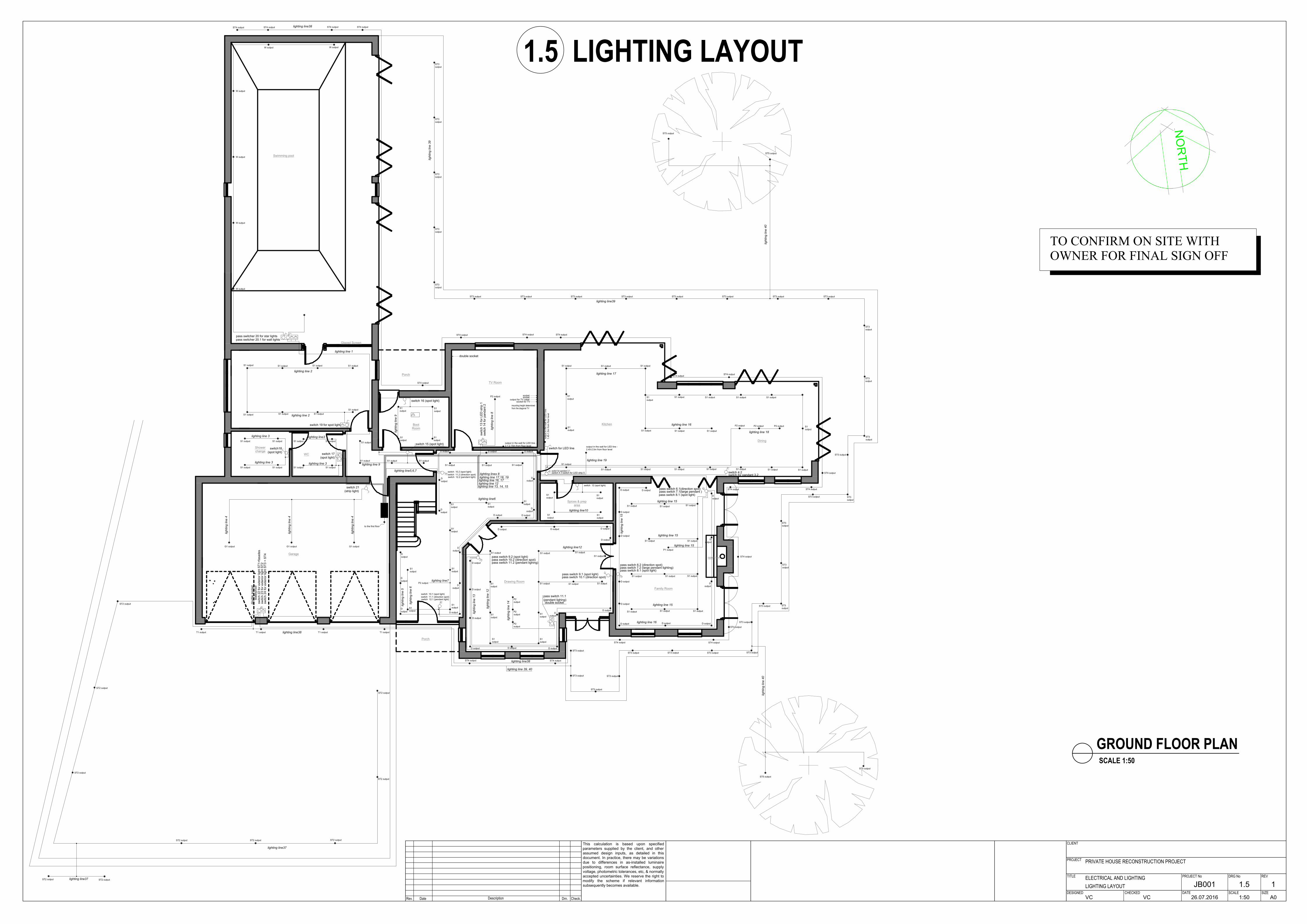
ELECTRICAL AND LIGHTINGLIGHTING LAYOUT JB001 1.5 1
VC VC 26.07.2016 1:50 A0
GROUND FLOOR PLANSCALE 1:50
TO CONFIRM ON SITE WITHOWNER FOR FINAL SIGN OFF
1.5 LIGHTING LAYOUT
En - Suite 1
Bedroom 1
En - Suite 3
En - Suite 4
En - Suite 2
Bedroom 2
Bedroom 3
Bedroom 4
En - Suite
Dressing
room
Balconey
Laundry
Room
Dressing
room
Gallery Landing
down
up
sw
itch
2
7
( E
n -su
ite
1
)
S2
output
S2
output
S2
output
S2
output
P1
output
D output
D output
D output
S1
output
S1
output
S1
output
S2
output
S2
output
S2 output
S2 output S2 output
S2
output
S2
output
switch 25 (pendan lighing)
switch 26 (small spots)
D
output
D
output
D
output
S1
output
S1
output
S1
output
S1
output
switch 22
( En -suite 2)
sw
itch
3
0 (sm
all sp
ots)
sw
itch
3
1(d
ire
ctio
n sp
ots)
sw
itch
3
2(p
en
da
n lig
hin
g)
S2
output
S2
output
S2
output
S2
output
S2
output
S2
output
S2
output
S2 output
P1
output
P1
output
S2
output
sw
itch
3
4(p
en
da
n lig
hin
g)
sw
itch
3
3(sm
all sp
ots)
S1
output
S1
output
S1
output
S2
output
S2
output
S2
output
2xS2
output
P1
output
sw
itch
1
9
(d
ire
ctio
n sp
ots)
switch 35(En -suite 3)
S1
output
S1
output
S1
output
S1
output
S1
output
S1
output
switch 40( En -suite 4)
S1
output
S1
output
S1
output
switch 37 (spot light)
switch 38 (pendan lighing)
switch 39 (small spots)
S2 output
S2 output
2хS2 output
S2
output
12x S2
output
S2 output S2 output S2 output
S1
output
S1
output
S1
output
S1
output
S1
output
S1
output
S1
output
S1
output
S1
output
S1
output
S1
output
S1
output
S1
output
S1
output
S1
output
S1
output
S1
output
S1
output
S1
output
S1
output
S1
output
S1 output
S1
output
S1
output
S1
output
S1
output
S1
output
S1
output
S1output S1output
S1output
4xS2 output
S2
output
S2
output
S2
output
for graund floor
S2
output
S2
output
9хS2
output
4хS2
output
double switch 29.1
(small spots/ spot lighting)
double switch 29.2
(smoll spots/
spot lighting)
sw
itch
3
6
(sp
ot lig
ht)
switch 41
(spot light)
switch 42
(spot light)
switch 43
(spot light)
lig
htin
g lin
e 1
5
lig
htin
g lin
e 1
6
lighting line 17
lighting line 28
S1 output
lighting line 19
lighting line 19
lighting line 20
lighting line 20
lighting line 21
lighting line 23
lighting line 21
lighting line 22
lighting line 18
lighting line 16
lighting line 15
lighting line 22
lighting line 23
lighting line 17
lighting line 19
lighting line 24
lighting line 25
lighting line 26
lighting line 27
lighting line 28.1
lighting line28.2
lighting line 29
lig
htin
g lin
e 3
2.1
lig
htin
g lin
e 3
0
lighting line 31
lighting line 32.2
lighting line 29,30,31,33
lighting line 28.1, 28.2
lighting line 32.1, 32.2
lighting lines 24,25,26,27
S2
output
S2
output
S2
output
S2 output S2 outputS2 output
S2 output
S2 outputS2 output
S2 output
S2 output
S2 output S2 output
S2
output
S2
output
S2
output
switch 44 for LED line
lighting line 33
LED line
output
photosensitive detector(depends on natural lux level)
D
PROJECT
CLIENT
TITLE
DATEDESIGNED
REV
SIZESCALE
PROJECT No
CHECKED
DRG No
Rev. Description Drn. Check.Date
This calculation is based upon specified
parameters supplied by the client, and other
assumed design inputs, as detailed in this
document. In practice, there may be variations
due to differences in as-installed luminaire
positioning, room surface reflectance, supply
voltage, photometric tolerances, etc, & normally
accepted uncertainties. We reserve the right to
modify the scheme if relevant information
subsequently becomes available.
PRIVATE HOUSE RECONSTRUCTION PROJECT
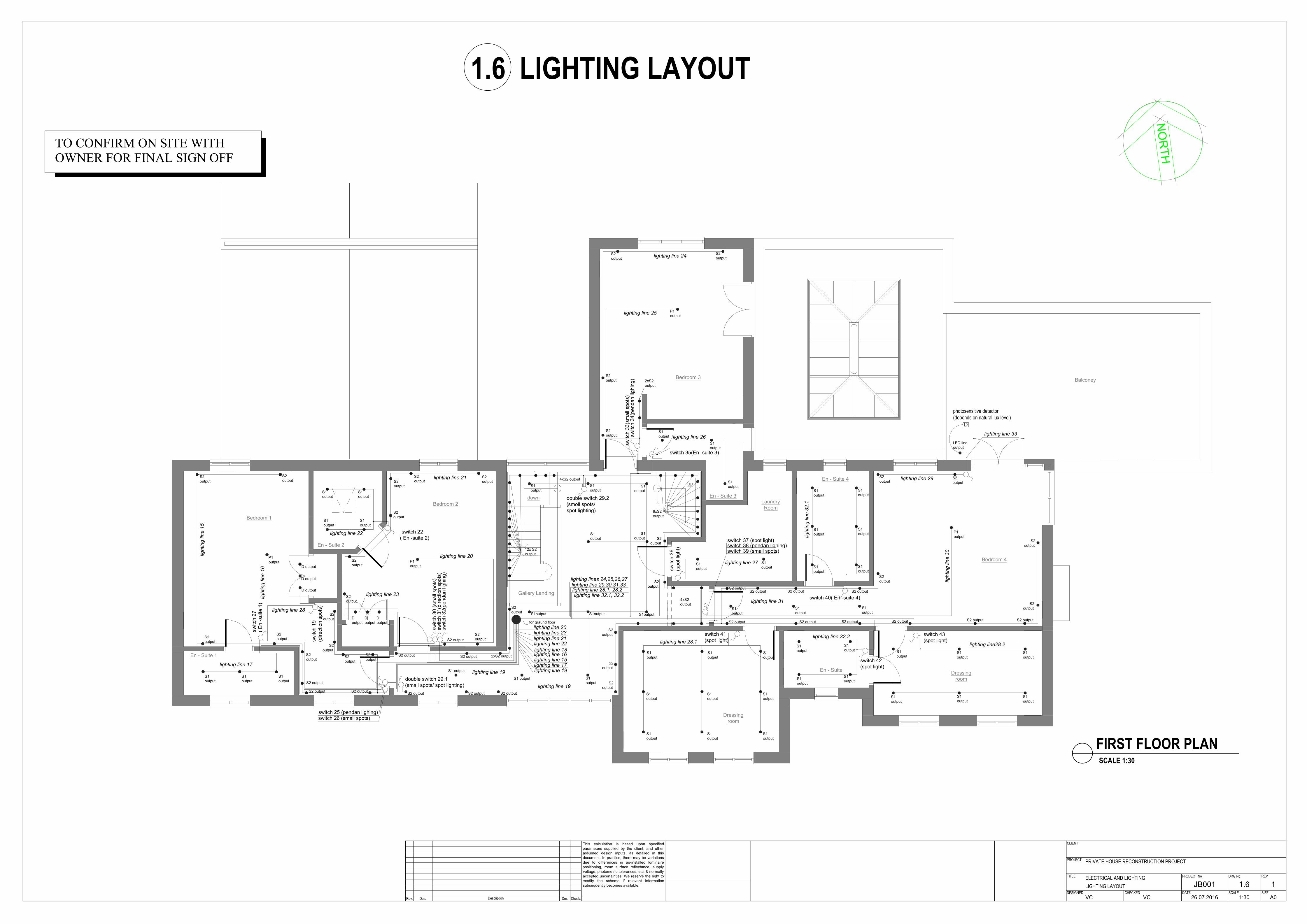
ELECTRICAL AND LIGHTINGLIGHTING LAYOUT JB001 1.6 1
VC VC 26.07.2016 1:30 A0
FIRST FLOOR PLANSCALE 1:30
1.6 LIGHTING LAYOUT
TO CONFIRM ON SITE WITHOWNER FOR FINAL SIGN OFF

Rev. Description Drn. CheckedDate
PROJECT
CLIENT
TITLE
DATEDESIGNED
REV
SIZESCALE
PROJECT No
CHECKED
DRG No
PRIVATE HOUSE RECONSTRUCTION PROJECT
LIGHTING SPECIFICATION JB001 1.7 1
VC VC 26.07.2016 -//- A3
1.7 LIGHTING SPECIFICATIONSYMBOL TYPE DESCRIPTION QTY.
S1 SPOT LIGHT 136
S2 SMALL SPOT 85
D1 DIRECTIONAL SPOT LIGHT 6
D DIRECTION SPOT 40
S STAR LIGHTS 1
LED LED STRIP
P1 LARGE PENDANT 7
P2 PENDANT 2
T1 TABLE LAMP 2
T2 TABLE LAMP 2
T3 TABLE LAMP 4
T4 TABLE LAMP 2
ST1 LIGHT UP 4
ST2 DRIVEWAY LIGHTS 10
ST3 FLOOD LIGHTS 32
ST4 FLOOD LIGHTS 4
ST5 WALL LIGHTS 19
G1 GARAGE LINEAR LUMINAIRES 3
W POOL WALL LIGHTS 6
LIGHT SENSOR 8
TV
M
int
IR
D
intercom
phone
security
INFRA-RED SENSOR
MUSIC SYSTEM
TV/VIDEO SYSTEM
INTERNET DEVICES
PHOTOSENSITIVE DETECTOR(DEPENDS ON NATURAL LUX LEVEL)
INTERCOM STATION & PHONEOUTPUT
SECURITY SYSTEM MONITOR

LUSIN LIGHTING DESIGN | 2016 www.lusinlightingdesign.com
Top Related