


Languages
Pages
Legal


Relion® Protection and Control
670 series 2.0 IECLON Communication Protocol Manual


Document ID: 1MRK 511 305-UENIssued: May 2014
Revision: -Product version: 2.0
© Copyright 2014 ABB. All rights reserved

CopyrightThis document and parts thereof must not be reproduced or copied without writtenpermission from ABB, and the contents thereof must not be imparted to a thirdparty, nor used for any unauthorized purpose.
The software and hardware described in this document is furnished under a licenseand may be used or disclosed only in accordance with the terms of such license.
This product includes software developed by the OpenSSL Project for use in theOpenSSL Toolkit. (http://www.openssl.org/)
This product includes cryptographic software written/developed by: Eric Young([email protected]) and Tim Hudson ([email protected]).
TrademarksABB and Relion are registered trademarks of the ABB Group. All other brand orproduct names mentioned in this document may be trademarks or registeredtrademarks of their respective holders.
WarrantyPlease inquire about the terms of warranty from your nearest ABB representative.

DisclaimerThe data, examples and diagrams in this manual are included solely for the conceptor product description and are not to be deemed as a statement of guaranteedproperties. All persons responsible for applying the equipment addressed in thismanual must satisfy themselves that each intended application is suitable andacceptable, including that any applicable safety or other operational requirementsare complied with. In particular, any risks in applications where a system failure and/or product failure would create a risk for harm to property or persons (including butnot limited to personal injuries or death) shall be the sole responsibility of theperson or entity applying the equipment, and those so responsible are herebyrequested to ensure that all measures are taken to exclude or mitigate such risks.
This document has been carefully checked by ABB but deviations cannot becompletely ruled out. In case any errors are detected, the reader is kindly requestedto notify the manufacturer. Other than under explicit contractual commitments, inno event shall ABB be responsible or liable for any loss or damage resulting fromthe use of this manual or the application of the equipment.

ConformityThis product complies with the directive of the Council of the EuropeanCommunities on the approximation of the laws of the Member States relating toelectromagnetic compatibility (EMC Directive 2004/108/EC) and concerningelectrical equipment for use within specified voltage limits (Low-voltage directive2006/95/EC). This conformity is the result of tests conducted by ABB inaccordance with the product standard EN 60255-26 for the EMC directive, andwith the product standards EN 60255-1 and EN 60255-27 for the low voltagedirective. The product is designed in accordance with the international standards ofthe IEC 60255 series.

Table of contents
Section 1 Introduction.......................................................................3This manual........................................................................................3Intended audience..............................................................................3Product documentation.......................................................................4
Product documentation set............................................................4Document revision history.............................................................5Related documents........................................................................6
Document symbols and conventions..................................................7Symbols.........................................................................................7Document conventions..................................................................8Functions included in 670 series IEDs..........................................9
Section 2 LON application..............................................................19Application........................................................................................19
The LON Protocol...................................................................20Hardware and software modules............................................20
Section 3 LON operation principle..................................................21Operation principle...........................................................................21
LON protocol..........................................................................21Horizontal communication......................................................24Communication ports.............................................................27
Section 4 LON settings...................................................................41Settings.............................................................................................41
Section 5 LON technical data.........................................................43Technical data..................................................................................43
Section 6 Establishing connection and verifyingthe LON communication.................................................45Establishing connection and verifying the LONcommunication ................................................................................45
Communication via the rear ports ...............................................45LON communication...............................................................45
Settings........................................................................................45Optical budget calculation for serial communication withLON .......................................................................................47Reference...............................................................................47
Section 7 LON Functions...............................................................49
Table of contents
670 series 2.0 IEC 1Communication Protocol Manual

Event function EVENT......................................................................49Identification................................................................................49Function block.............................................................................49Signals.........................................................................................50Settings........................................................................................51Operation principle......................................................................53
MULTICMDRCV and MULTICMDSND............................................54Application...................................................................................54Design.........................................................................................54
General...................................................................................54Function block.............................................................................55Signals.........................................................................................56Settings........................................................................................57Operation principle......................................................................57
Synchronization alternatives.............................................................57Synchronization via Serial Communication Module (SLM)..........57
Settings.............................................................................................58
Section 8 Glossary.........................................................................59Glossary...........................................................................................59
Table of contents
2 670 series 2.0 IECCommunication Protocol Manual

Section 1 Introduction
1.1 This manual
The communication protocol manual describes the communication protocolssupported by the IED. The manual concentrates on the vendor-specificimplementations.
1.2 Intended audience
This manual addresses the communication system engineer or system integratorresponsible for pre-engineering and engineering for communication setup in asubstation from an IED perspective.
The system engineer or system integrator must have a basic knowledge ofcommunication in protection and control systems and thorough knowledge of thespecific communication protocol.
1MRK 511 305-UEN - Section 1Introduction
670 series 2.0 IEC 3Communication Protocol Manual
1.3 Product documentation
1.3.1 Product documentation set
IEC07000220-4-en.vsd
Pla
nnin
g &
pur
chas
e
Eng
inee
ring
Inst
allin
g
Com
mis
sion
ing
Ope
ratio
n
Mai
nten
ance
Dec
omm
issi
onin
gD
eins
talli
ng &
dis
posa
l
Application manual
Operation manual
Installation manual
Engineering manual
Communication protocol manual
Cyber security deployment guideline
Technical manual
Commissioning manual
IEC07000220 V4 EN
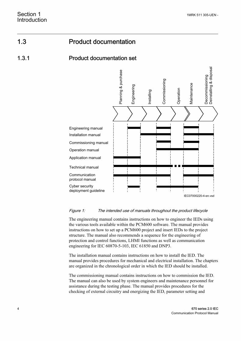
Figure 1: The intended use of manuals throughout the product lifecycle
The engineering manual contains instructions on how to engineer the IEDs usingthe various tools available within the PCM600 software. The manual providesinstructions on how to set up a PCM600 project and insert IEDs to the projectstructure. The manual also recommends a sequence for the engineering ofprotection and control functions, LHMI functions as well as communicationengineering for IEC 60870-5-103, IEC 61850 and DNP3.
The installation manual contains instructions on how to install the IED. Themanual provides procedures for mechanical and electrical installation. The chaptersare organized in the chronological order in which the IED should be installed.
The commissioning manual contains instructions on how to commission the IED.The manual can also be used by system engineers and maintenance personnel forassistance during the testing phase. The manual provides procedures for thechecking of external circuitry and energizing the IED, parameter setting and
Section 1 1MRK 511 305-UEN -Introduction
4 670 series 2.0 IECCommunication Protocol Manual

configuration as well as verifying settings by secondary injection. The manualdescribes the process of testing an IED in a substation which is not in service. Thechapters are organized in the chronological order in which the IED should becommissioned. The relevant procedures may be followed also during the serviceand maintenance activities.
The operation manual contains instructions on how to operate the IED once it hasbeen commissioned. The manual provides instructions for the monitoring,controlling and setting of the IED. The manual also describes how to identifydisturbances and how to view calculated and measured power grid data todetermine the cause of a fault.
The application manual contains application descriptions and setting guidelinessorted per function. The manual can be used to find out when and for what purposea typical protection function can be used. The manual can also provide assistancefor calculating settings.
The technical manual contains application and functionality descriptions and listsfunction blocks, logic diagrams, input and output signals, setting parameters andtechnical data, sorted per function. The manual can be used as a technical referenceduring the engineering phase, installation and commissioning phase, and duringnormal service.
The communication protocol manual describes the communication protocolssupported by the IED. The manual concentrates on the vendor-specificimplementations.
The point list manual describes the outlook and properties of the data pointsspecific to the IED. The manual should be used in conjunction with thecorresponding communication protocol manual.
The cyber security deployment guideline describes the process for handling cybersecurity when communicating with the IED. Certification, Authorization with rolebased access control, and product engineering for cyber security related events aredescribed and sorted by function. The guideline can be used as a technicalreference during the engineering phase, installation and commissioning phase, andduring normal service.
1.3.2 Document revision historyDocument revision/date History-/May 2014 First release
1MRK 511 305-UEN - Section 1Introduction
670 series 2.0 IEC 5Communication Protocol Manual

1.3.3 Related documentsDocuments related to REB670 Identify numberApplication manual 1MRK 505 302-UEN
Commissioning manual 1MRK 505 304-UEN
Product guide 1MRK 505 305-BEN
Technical manual 1MRK 505 303-UEN
Type test certificate 1MRK 505 305-TEN
Documents related to REC670 Identify numberApplication manual 1MRK 511 310-UEN
Commissioning manual 1MRK 511 312-UEN
Product guide 1MRK 511 313-BEN
Technical manual 1MRK 511 311-UEN
Type test certificate 1MRK 511 313-TEN
Documents related to RED670 Identify numberApplication manual 1MRK 505 307-UEN
Commissioning manual 1MRK 505 309-UEN
Product guide 1MRK 505 310-BEN
Technical manual 1MRK 505 308-UEN
Type test certificate 1MRK 505 310-TEN
Documents related to REG670 Identify numberApplication manual 1MRK 502 051-UEN
Commissioning manual 1MRK 502 053-UEN
Product guide 1MRK 502 054-BEN
Technical manual 1MRK 502 052-UEN
Type test certificate 1MRK 502 054-TEN
Documents related to REL670 Identify numberApplication manual 1MRK 506 338-UEN
Commissioning manual 1MRK 506 340-UEN
Product guide 1MRK 506 341-BEN
Technical manual 1MRK 506 339-UEN
Type test certificate 1MRK 506 341-TEN
Section 1 1MRK 511 305-UEN -Introduction
6 670 series 2.0 IECCommunication Protocol Manual

Documents related to RET670 Identify numberApplication manual 1MRK 504 138-UEN
Commissioning manual 1MRK 504 140-UEN
Product guide 1MRK 504 141-BEN
Technical manual 1MRK 504 139-UEN
Type test certificate 1MRK 504 141-TEN
670 series manuals Identify numberOperation manual 1MRK 500 118-UEN
Engineering manual 1MRK 511 308-UEN
Installation manual 1MRK 514 019-UEN
Communication protocol manual, IEC60870-5-103
1MRK 511 304-UEN
Communication protocol manual, IEC 61850Edition 1
1MRK 511 302-UEN
Communication protocol manual, IEC 61850Edition 2
1MRK 511 303-UEN
Communication protocol manual, LON 1MRK 511 305-UEN
Communication protocol manual, SPA 1MRK 511 306-UEN
Accessories guide 1MRK 514 012-BEN
Cyber security deployment guideline 1MRK 511 309-UEN
Connection and Installation components 1MRK 513 003-BEN
Test system, COMBITEST 1MRK 512 001-BEN
1.4 Document symbols and conventions
1.4.1 Symbols
The caution icon indicates important information or warning relatedto the concept discussed in the text. It might indicate the presenceof a hazard which could result in corruption of software or damageto equipment or property.
The information icon alerts the reader of important facts andconditions.
The tip icon indicates advice on, for example, how to design yourproject or how to use a certain function.
1MRK 511 305-UEN - Section 1Introduction
670 series 2.0 IEC 7Communication Protocol Manual

Although warning hazards are related to personal injury, it is necessary tounderstand that under certain operational conditions, operation of damagedequipment may result in degraded process performance leading to personal injuryor death. It is important that the user fully complies with all warning andcautionary notices.
1.4.2 Document conventions• Abbreviations and acronyms in this manual are spelled out in the glossary. The
glossary also contains definitions of important terms.• Push button navigation in the LHMI menu structure is presented by using the
push button icons.For example, to navigate between the options, use and .
• HMI menu paths are presented in bold.For example, select Main menu/Settings.
• LHMI messages are shown in Courier font.For example, to save the changes in non-volatile memory, select Yes andpress .
• Parameter names are shown in italics.For example, the function can be enabled and disabled with the Operation setting.
• Each function block symbol shows the available input/output signal.• the character ^ in front of an input/output signal name indicates that the
signal name may be customized using the PCM600 software.• the character * after an input/output signal name indicates that the signal
must be connected to another function block in the applicationconfiguration to achieve a valid application configuration.
• Logic diagrams describe the signal logic inside the function block and arebordered by dashed lines.• Signals in frames with a shaded area on their right hand side represent
setting parameter signals that are only settable via the PST or LHMI.• If an internal signal path cannot be drawn with a continuous line, the
suffix -int is added to the signal name to indicate where the signal startsand continues.
• Signal paths that extend beyond the logic diagram and continue inanother diagram have the suffix ”-cont.”
Section 1 1MRK 511 305-UEN -Introduction
8 670 series 2.0 IECCommunication Protocol Manual

1.4.3 Functions included in 670 series IEDsTable 1: Main protection functions
IEC 61850 or functionname
ANSI Description
Differential protection
BBP3PH4B 87B Busbar differential protection, 2 zones, three phase/4 baysPackage including functions BUTPTRC_B1-BUTPTRC_B4, BCZTPDIF, BZNTPDIF_A,BZNTPDIF_B, BZITGGIO, BUTSM4
BBP3PH8B 87B Busbar differential protection, 2 zones, three phase/8 baysPackage including functions BUTPTRC_B1-BUTPTRC_B8, BCZTPDIF, BZNTPDIF_A,BZNTPDIF_B, BZITGGIO, BUTSM8
BBP1PH12B 87B Busbar differential protection, 2 zones, single phase/12 baysPackage including functions BUSPTRC_B1-BUSPTRC_B12, BCZSPDIF, BZNSPDIF_A,BZNSPDIF_B, BZISGGIO, BUSSM12
BBP1PH24B 87B Busbar differential protection, 2 zones, single phase/24 baysPackage including functions BUSPTRC_B1-BUSPTRC_B24, BCZSPDIF, BZNSPDIF_A,BZNSPDIF_B, BZISGGIO, BUSSM24
BDCGAPC 87B Status of primary switching object for busbar protection zone selection
T2WPDIF 87T Transformer differential protection, two winding
T3WPDIF 87T Transformer differential protection, three winding
HZPDIF 87 1Ph High impedance differential protection
GENPDIF 87G Generator differential protection
REFPDIF 87N Restricted earth fault protection, low impedance
L3CPDIF 87L Line differential protection, 3 CT sets, 23 line ends
L6CPDIF 87L Line differential protection, 6 CT sets, 35 line ends
LT3CPDIF 87LT Line differential protection 3 CT sets, with inzone transformers, 23 line ends
LT6CPDIF 87LT Line differential protection 6 CT sets, with inzone transformers, 35 line ends
LDLPSCH 87L Line differential coordination function
LDRGFC 11REL Additional security logic for differential protection
Impedance protection
ZMQAPDIS, ZMQPDIS 21 Distance protection zone, quadrilateral characteristic
ZDRDIR 21D Directional impedance quadrilateral
ZMCPDIS, ZMCAPDIS 21 Distance measuring zone, quadrilateral characteristic for series compensated lines
ZDSRDIR 21D Directional impedance quadrilateral, including series compensation
FDPSPDIS 21 Phase selection, quadrilateral characteristic with fixed angle
ZMHPDIS 21 Full-scheme distance protection, mho characteristic
ZMMPDIS, ZMMAPDIS 21 Fullscheme distance protection, quadrilateral for earth faults
ZDMRDIR 21D Directional impedance element for mho characteristic
ZDARDIR Additional distance protection directional function for earth faults
ZSMGAPC Mho Impedance supervision logic
FMPSPDIS 21 Faulty phase identification with load enchroachment
ZMRPDIS, ZMRAPDIS 21 Distance protection zone, quadrilateral characteristic, separate settings
FRPSPDIS 21 Phase selection, quadrilateral characteristic with settable angle
Table continues on next page
1MRK 511 305-UEN - Section 1Introduction
670 series 2.0 IEC 9Communication Protocol Manual

IEC 61850 or functionname
ANSI Description
ZMFPDIS 21 High speed distance protection
ZMFCPDIS 21 High speed distance protection for series compensated lines
ZMCAPDIS Additional distance measuring zone, quadrilateral characteristic
ZMRPSB 68 Power swing detection
PSLPSCH Power swing logic
PSPPPAM 78 Pole slip/out-of-step protection
OOSPPAM 78 Out-of-step protection
ZCVPSOF Automatic switch onto fault logic, voltage and current based
LEXPDIS 40 Loss of excitation
PPLPHIZ Phase preference logic
ROTIPHIZ 64R Sensitive rotor earth fault protection, injection based
STTIPHIZ 64S 100% stator earth fault protection, injection based
ZGVPDIS 21 Underimpedance protection for generators and transformers
Table 2: Backup protection functions
IEC 61850 or functionname
ANSI Description
Current protection
PHPIOC 50 Instantaneous phase overcurrent protection
OC4PTOC 51_67 Four step phase overcurrent protection
PH4SPTOC 51 Four step single phase overcurrent protection
EFPIOC 50N Instantaneous residual overcurrent protection
EF4PTOC 51N_67N
Four step residual overcurrent protection
NS4PTOC 46I2 Four step directional negative phase sequence overcurrent protection
SDEPSDE 67N Sensitive directional residual over current and power protection
LCPTTR 26 Thermal overload protection, one time constant, Celsius
LFPTTR 26 Thermal overload protection, one time constant, Fahrenheit
TRPTTR 49 Thermal overload protection, two time constants
CCRBRF 50BF Breaker failure protection
CCSRBRF 50BF Breaker failure protection, single phase version
STBPTOC 50STB Stub protection
CCPDSC 52PD Pole discordance protection
GUPPDUP 37 Directional underpower protection
GOPPDOP 32 Directional overpower protection
BRCPTOC 46 Broken conductor check
CBPGAPC Capacitor bank protection
NS2PTOC 46I2 Negative sequence time overcurrent protection for machines
AEGPVOC 50AE Accidental energizing protection for synchronous generator
Table continues on next page
Section 1 1MRK 511 305-UEN -Introduction
10 670 series 2.0 IECCommunication Protocol Manual

IEC 61850 or functionname
ANSI Description
VRPVOC 51V Voltage restrained overcurrent protection
GSPTTR 49S Stator overload protection
GRPTTR 49R Rotor overload protection
Voltage protection
UV2PTUV 27 Two step undervoltage protection
OV2PTOV 59 Two step overvoltage protection
ROV2PTOV 59N Two step residual overvoltage protection
OEXPVPH 24 Overexcitation protection
VDCPTOV 60 Voltage differential protection
STEFPHIZ 59THD 100% Stator earth fault protection, 3rd harmonic based
LOVPTUV 27 Loss of voltage check
PAPGAPC 27 Radial feeder protection
Frequency protection
SAPTUF 81 Underfrequency protection
SAPTOF 81 Overfrequency protection
SAPFRC 81 Rate-of-change frequency protection
FTAQFVR 81A Frequency time accumulation protection
Multipurpose protection
CVGAPC General current and voltage protection
Table 3: Control and monitoring functions
IEC 61850 or functionname
ANSI Description
Control
SESRSYN 25 Synchrocheck, energizing check, and synchronizing
SMBRREC 79 Autorecloser
TR1ATCC 90 Automatic voltage control for tap changer, single control
TR8ATCC 90 Automatic voltage control for tap changer, parallel control
TCMYLTC 84 Tap changer control and supervision, 6 binary inputs
TCLYLTC 84 Tap changer control and supervision, 32 binary inputs
SLGAPC Logic Rotating Switch for function selection and LHMI presentation
VSGAPC Selector mini switch
DPGAPC Generic communication function for Double Point indication
SPC8GAPC Single Point Generic Control 8 signals
AUTOBITS AutomationBits, command function for DNP3.0
SINGLECMD Single command, 16 signalsCommand function block for LON and SPA
VCTRSEND Horizontal communication via GOOSE for VCTR
GOOSEVCTRRCV Horizontal communication via GOOSE for VCTR
Table continues on next page
1MRK 511 305-UEN - Section 1Introduction
670 series 2.0 IEC 11Communication Protocol Manual
IEC 61850 or functionname
ANSI Description
I103CMD Function commands for IEC60870-5-103
I103GENCMD Function commands generic for IEC60870-5-103
I103POSCMD IED commands with position and select for IEC60870-5-103
I103IEDCMD IED commands for IEC60870-5-103
I103USRCMD Function commands user defined for IEC60870-5-103
Apparatus control and interlocking
SCILO 3 Logical node for interlocking
BB_ES 3 Interlocking for busbar earthing switch
A1A2_BS 3 Interlocking for bus-section breaker
A1A2_DC 3 Interlocking for bus-section disconnector
ABC_BC 3 Interlocking for bus-coupler bay
BH_CONN 3 Interlocking for 1 1/2 breaker diameter
BH_LINE_A 3 Interlocking for 1 1/2 breaker diameter
BH_LINE_B 3 Interlocking for 1 1/2 breaker diameter
DB_BUS_A 3 Interlocking for double CB bay
DB_BUS_B 3 Interlocking for double CB bay
DB_LINE 3 Interlocking for double CB bay
ABC_LINE 3 Interlocking for line bay
AB_TRAFO 3 Interlocking for transformer bay
SCSWI Switch controller
SXCBR Circuit breaker
SXSWI Switch controller
RESIN1 Reservation input 1
RESIN2 Reservation input 2
POS_EVAL Evaluation of position indication
QCRSV Bay reservation
QCBAY Apparatus controlFunction for handling the status of Local/Remote switch
LOCREM Handling of LRswitch positions
LOCREMCTRL LHMI control of PSTOFunction for handling Internal Local/Remote switch
Secondary system supervision
CCSSPVC 87 Current circuit supervision
FUFSPVC Fuse failure supervision
VDSPVC 60 Fuse failure supervision based on voltage difference
Logic
SMPPTRC 94 Tripping logic
TMAGAPC Trip matrix logic
ALMCALH Logic for group alarm
WRNCALH Logic for group warning
Table continues on next page
Section 1 1MRK 511 305-UEN -Introduction
12 670 series 2.0 IECCommunication Protocol Manual
IEC 61850 or functionname
ANSI Description
INDCALH Logic for group indication
AND Configurable logic blocks, AND
OR Configurable logic blocks, OR
INV Configurable logic blocks, inverter
PULSETIMER Configurable logic blocks, PULSETIMER
GATE Configurable logic blocks, controllable gate
TIMERSET Configurable logic blocks, timer
XOR Configurable logic blocks, exclusive OR
LLD Configurable logic blocks, LLD
SRMEMORY Configurable logic blocks, set-reset memory
RSMEMORY Configurable logic blocks, reset-set memory
ANDQT Configurable logic blocks Q/T, ANDQT
ORQT Configurable logic blocks Q/T, ORQT
INVERTERQT Configurable logic blocks Q/T, INVERTERQT
XORQT Configurable logic blocks Q/T, XORQT
SRMEMORYQT Configurable logic Q/T, set-reset with memory
RSMEMORYQT Configurable logic Q/T, reset-set with memory
TIMERSETQT Configurable logic Q/T, settable timer
PULSETIMERQT Configurable logic Q/T, pulse timer
INVALIDQT Configurable logic Q/T, INVALIDQT
INDCOMBSPQT Configurable logic Q/T, single-indication signal combining
INDEXTSPQT Configurable logic Q/T, single-indication signal extractor
FXDSIGN Fixed signal function block
B16I Boolean 16 to Integer conversion
BTIGAPC Boolean 16 to Integer conversion with Logic Node representation
IB16 Integer to Boolean 16 conversion
ITBGAPC Integer to Boolean 16 conversion with Logic Node representation
TIGAPC Delay on timer with input signal integration
TEIGAPC Elapsed time integrator with limit transgression and overflow supervision
Monitoring
CVMMXN, CMMXU,VMMXU, CMSQIVMSQI, VNMMXU
Measurements
AISVBAS Function block for service value presentation of secondary analog inputs
SSIMG 63 Gas medium supervision
SSIML 71 Liquid medium supervision
SSCBR Circuit breaker condition monitoring
EVENT Event functionFunction for event reporting for LON and SPA
Table continues on next page
1MRK 511 305-UEN - Section 1Introduction
670 series 2.0 IEC 13Communication Protocol Manual

IEC 61850 or functionname
ANSI Description
DRPRDRE, A1RADR-A4RADR, B1RBDR-B6RBDR
Disturbance report
SPGAPC Generic communication function for Single Point indication
SP16GAPC Generic communication function for Single Point indication 16 inputs
MVGAPC Generic communication function for Measured Value
BINSTATREP Logical signal status report
RANGE_XP Measured value expander block
LMBRFLO Fault locator
I103MEAS Measurands for IEC60870-5-103
I103MEASUSR Measurands user defined signals for IEC60870-5-103
I103AR Function status auto-recloser for IEC60870-5-103
I103EF Function status earth-fault for IEC60870-5-103
I103FLTPROT Function status fault protection for IEC60870-5-103
I103IED IED status for IEC60870-5-103
I103SUPERV Supervison status for IEC60870-5-103
I103USRDEF Status for user defiend signals for IEC60870-5-103
L4UFCNT Event counter with limit supervision
Metering
PCFCNT Pulse-counter logic
ETPMMTR Function for energy calculation and demand handling
System protection and control
SMAIHPAC Multipurpose filter
Table 4: Station communication functions
IEC 61850 or functionname
ANSI Description
Station communication
SPA SPA communication protocol
ADE LON communciation protocol
PROTOCOL Operation selection between SPA and IEC60870-5-103 for SLM
CHSERRS485 DNP3.0 for TCP/IP and EIA-485 communication protocol
DNPFREC DNP3.0 fault records for TCP/IP and EIA-485 communication protocol
IEC61850-8-1 Parameter setting function for IEC61850
GOOSEINTLKRCV Horizontal communication via GOOSE for interlocking
GOOSEBINRCV Goose binary receive
GOOSEDPRCV GOOSE function block to receive a double point value
GOOSEINTRCV GOOSE function block to receive an integer value
GOOSEMVRCV GOOSE function block to receive a measurand value
Table continues on next page
Section 1 1MRK 511 305-UEN -Introduction
14 670 series 2.0 IECCommunication Protocol Manual

IEC 61850 or functionname
ANSI Description
GOOSESPRCV GOOSE function block to receive a single point value
GOOSEVCTRCONF GOOSE VCTR configuration for send and receive
VCTRSEND Horizontal communication via GOOSE for VCTR
GOOSEVCTRRCV Horizontal communication via GOOSE for VCTR
MULTICMDRCV,MULTICMDSND
Multiple command and transmit
FRONT, LANABI,LANAB, LANCDI,LANCD
Ethernet configuration of links
MU1_4I_4U MU2_4I_4UMU3_4I_4U MU4_4I_4UMU5_4I_4U MU6_4I_4U
Process bus communication IEC61850-9-2
PRP Duo driver configuration
Scheme communication
ZCPSCH 85 Scheme communication logic for distance or overcurrent protection
ZC1PPSCH 85 Phase segregated Scheme communication logic for distance protection
ZCRWPSCH 85 Current reversal and weak-end infeed logic for distance protection
ZC1WPSCH 85 Current reversal and weak-end infeed logic for phase segregated communication
ZCLCPSCH Local acceleration logic
ECPSCH 85 Scheme communication logic for residual overcurrent protection
ECRWPSCH 85 Current reversal and weak-end infeed logic for residual overcurrent protection
Direct transfer trip
LAPPGAPC 37_55 Low active power and power factor protection
COUVGAPC 59_27 Compensated over- and undervoltage protection
SCCVPTOC 51 Sudden change in current variation
LCCRPTRC 94 Carrier receive logic
LCNSPTOV 47 Negative sequence overvoltage protection
LCZSPTOV 59N Zero sequence overvoltage protection
LCNSPTOC 46 Negative sequence overcurrent protection
LCZSPTOC 51N Zero sequence overcurrent protection
LCP3PTOC 51 Three phase overcurrent
LCP3PTUC 37 Three phase undercurrent
Table 5: Basic IED functions
IEC 61850 or functionname
Description
INTERRSIG Self supervision with internal event list
SELFSUPEVLST Self supervision with internal event list
TIMESYNCHGEN Time synchronization module
Table continues on next page
1MRK 511 305-UEN - Section 1Introduction
670 series 2.0 IEC 15Communication Protocol Manual

IEC 61850 or functionname
Description
SYNCHBIN,SYNCHCAN,SYNCHCMPPS,SYNCHLON,SYNCHPPH,SYNCHPPS,SYNCHSNTP,SYNCHSPA,SYNCHCMPPS
Time synchronization
TIMEZONE Time synchronization
DSTBEGIN,DSTENABLE, DSTEND
GPS time synchronization module
IRIG-B Time synchronization
SETGRPS Number of setting groups
ACTVGRP Parameter setting groups
TESTMODE Test mode functionality
CHNGLCK Change lock function
LONGEN Misc Base Common
SMBI Signal matrix for binary inputs
SMBO Signal matrix for binary outputs
SMMI Signal matrix for mA inputs
SMAI1 - SMAI20 Signal matrix for analog inputs
3PHSUM Summation block 3 phase
ATHSTAT Authority status
ATHCHCK Authority check
AUTHMAN Authority management
FTPACCS FTP access with password
SPACOMMMAP SPA communication mapping
SPATD Date and time via SPA protocol
DOSFRNT Denial of service, frame rate control for front port
DOSLANAB Denial of service, frame rate control for OEM port AB
DOSLANCD Denial of service, frame rate control for OEM port CD
DOSSCKT Denial of service, socket flow control
GBASVAL Global base values for settings
PRIMVAL Primary system values
ALTMS Time master supervision
ALTIM Time management
ALTRK Service tracking
ACTIVLOG Activity logging parameters
FSTACCS Field service tool access via SPA protocol over ethernet communication
PCMACCS IED Configuration Protocol
SECALARM Component for mapping security events on protocols such as DNP3 and IEC103
Table continues on next page
Section 1 1MRK 511 305-UEN -Introduction
16 670 series 2.0 IECCommunication Protocol Manual

IEC 61850 or functionname
Description
DNPGEN DNP3.0 communication general protocol
DNPGENTCP DNP3.0 communication general TCP protocol
CHSEROPT DNP3.0 for TCP/IP and EIA-485 communication protocol
MSTSER DNP3.0 for serial communication protocol
OPTICAL103 IEC60870-5-103 Optical serial communication
RS485103 IEC60870-5-103 serial communication for RS485
IEC61850-8-1 Parameter setting function for IEC61850
HORZCOMM Network variables via LON
LONSPA SPA communication protocol
LEDGEN General LED indication part for LHMI
1MRK 511 305-UEN - Section 1Introduction
670 series 2.0 IEC 17Communication Protocol Manual

18

Section 2 LON application
2.1 Application
Control Center
IED IEDIED
Gateway
Star couplerRER 111
Station HSIMicroSCADA
IEC05000663-1-en.vsdIEC05000663 V2 EN
Figure 2: Example of LON communication structure for a substationautomation system
An optical network can be used within the substation automation system. Thisenables communication with the IEDs in the 670 series through the LON bus fromthe operator’s workplace, from the control center and also from other IEDs via bay-to-bay horizontal communication.
The fibre optic LON bus is implemented using either glass core or plastic core fibreoptic cables.
Table 6: Specification of the fibre optic connectors
Glass fibre Plastic fibreCable connector ST-connector snap-in connector
Cable diameter 62.5/125 m 1 mm
Max. cable length 1000 m 10 m
Wavelength 820-900 nm 660 nm
Transmitted power -13 dBm (HFBR-1414) -13 dBm (HFBR-1521)
Receiver sensitivity -24 dBm (HFBR-2412) -20 dBm (HFBR-2521)
1MRK 511 305-UEN - Section 2LON application
670 series 2.0 IEC 19Communication Protocol Manual

2.1.1.1 The LON Protocol
The LON protocol is specified in the LonTalkProtocol Specification Version 3from Echelon Corporation. This protocol is designed for communication in controlnetworks and is a peer-to-peer protocol where all the devices connected to thenetwork can communicate with each other directly. For more information of the bay-to-bay communication, refer to the section Multiple command function.
2.1.1.2 Hardware and software modules
The hardware needed for applying LON communication depends on theapplication, but one very central unit needed is the LON Star Coupler and opticalfibres connecting the star coupler to the IEDs. To interface the IEDs fromMicroSCADA, the application library LIB670 is required.
The HV Control 670 software module is included in the LIB520 high-voltageprocess package, which is a part of the Application Software Library withinMicroSCADA applications.
The HV Control 670 software module is used for control functions in IEDs in the670 series. This module contains the process picture, dialogues and a tool togenerate the process database for the control application in MicroSCADA.
Use the LON Network Tool (LNT) to set the LON communication. This is asoftware tool applied as one node on the LON bus. To communicate via LON, theIEDs need to know
• The node addresses of the other connected IEDs.• The network variable selectors to be used.
This is organized by LNT.
The node address is transferred to LNT via the local HMI by setting the parameterServicePinMsg = Yes. The node address is sent to LNT via the LON bus, or LNTcan scan the network for new nodes.
The communication speed of the LON bus is set to the default of 1.25 Mbit/s. Thiscan be changed by LNT.
Section 2 1MRK 511 305-UEN -LON application
20 670 series 2.0 IECCommunication Protocol Manual
Section 3 LON operation principle
3.1 Operation principle
The speed of the network depends on the medium and transceiver design. Withprotection and control devices, fibre optic media is used, which enables the use ofthe maximum speed of 1.25 Mbits/s. The protocol is a peer-to-peer protocol whereall the devices connected to the network can communicate with each other. Theown subnet and node number are identifying the nodes (max. 255 subnets, 127nodes per one subnet).
The LON bus links the different parts of the protection and control system. Themeasured values, status information, and event information are spontaneously sentto the higher-level devices. The higher-level devices can read and write memorizedvalues, setting values, and other parameter data when required. The LON bus alsoenables the bay level devices to communicate with each other to deliver, forexample, interlocking information among the terminals without the need of a busmaster.
The LonTalk protocol supports two types of application layer objects: networkvariables and explicit messages. Network variables are used to deliver shortmessages, such as measuring values, status information, and interlocking/blockingsignals. Explicit messages are used to transfer longer pieces of information, such asevents and explicit read and write messages to access device data.
The benefits achieved from using the LON bus in protection and control systemsinclude direct communication among all terminals in the system and support formulti-master implementations. The LON bus also has an open concept, so that theterminals can communicate with external devices using the same standard ofnetwork variables.
3.1.1.1 LON protocol
Configuration of LONLON network tool (LNT) is a multi-purpose tool for LonWorks networkconfiguration. All the functions required for setting up and configuring aLonWorks network, is easily accessible on a single tool program.
Activate LON CommunicationActivate LON communication in the Parameter Setting tool under Main menu/Communication/ SLM configuration/ Rear optical LON port/ Horizontalcommunication, where Operation must be set to ON.
1MRK 511 305-UEN - Section 3LON operation principle
670 series 2.0 IEC 21Communication Protocol Manual
Add LON Device Types LNTA new device is added to LON Network Tool from the Device menu or byinstalling the device from the ABB LON Device Types package for LNT 505, withthe SLDT 670 series package version 1p2 r03.
LON net addressTo establish a LON connection with the 670 series IEDs, the IED has to be given aunique net address. The net address consists of a subnet and node number. This isaccomplished with the LON Network Tool by creating one device for each IED.
Vertical communicationVertical communication describes communication between the monitoring devicesand protection and control IEDs. This communication includes sending of changedprocess data to monitoring devices as events and transfer of commands, parameterdata and disturbance recorder files. This communication is implemented usingexplicit messages.
Events and indicationsEvents sent to the monitoring devices are using explicit messages (message code44H) with unacknowledged transport service of the LonTalk protocol. When asignal is changed in the IED, one message with the value, quality and time istransmitted from terminal.
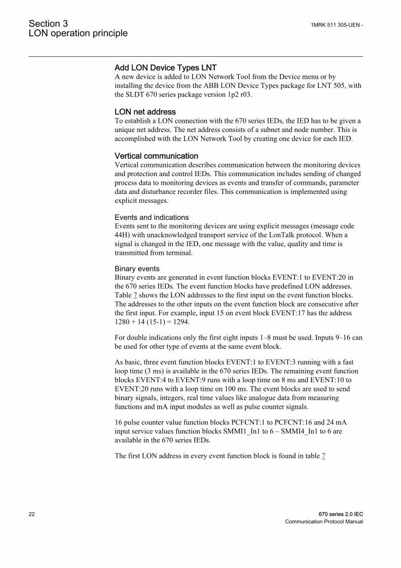
Binary eventsBinary events are generated in event function blocks EVENT:1 to EVENT:20 inthe 670 series IEDs. The event function blocks have predefined LON addresses.Table 7 shows the LON addresses to the first input on the event function blocks.The addresses to the other inputs on the event function block are consecutive afterthe first input. For example, input 15 on event block EVENT:17 has the address1280 + 14 (15-1) = 1294.
For double indications only the first eight inputs 1–8 must be used. Inputs 9–16 canbe used for other type of events at the same event block.
As basic, three event function blocks EVENT:1 to EVENT:3 running with a fastloop time (3 ms) is available in the 670 series IEDs. The remaining event functionblocks EVENT:4 to EVENT:9 runs with a loop time on 8 ms and EVENT:10 toEVENT:20 runs with a loop time on 100 ms. The event blocks are used to sendbinary signals, integers, real time values like analogue data from measuringfunctions and mA input modules as well as pulse counter signals.
16 pulse counter value function blocks PCFCNT:1 to PCFCNT:16 and 24 mAinput service values function blocks SMMI1_In1 to 6 – SMMI4_In1 to 6 areavailable in the 670 series IEDs.
The first LON address in every event function block is found in table 7
Section 3 1MRK 511 305-UEN -LON operation principle
22 670 series 2.0 IECCommunication Protocol Manual
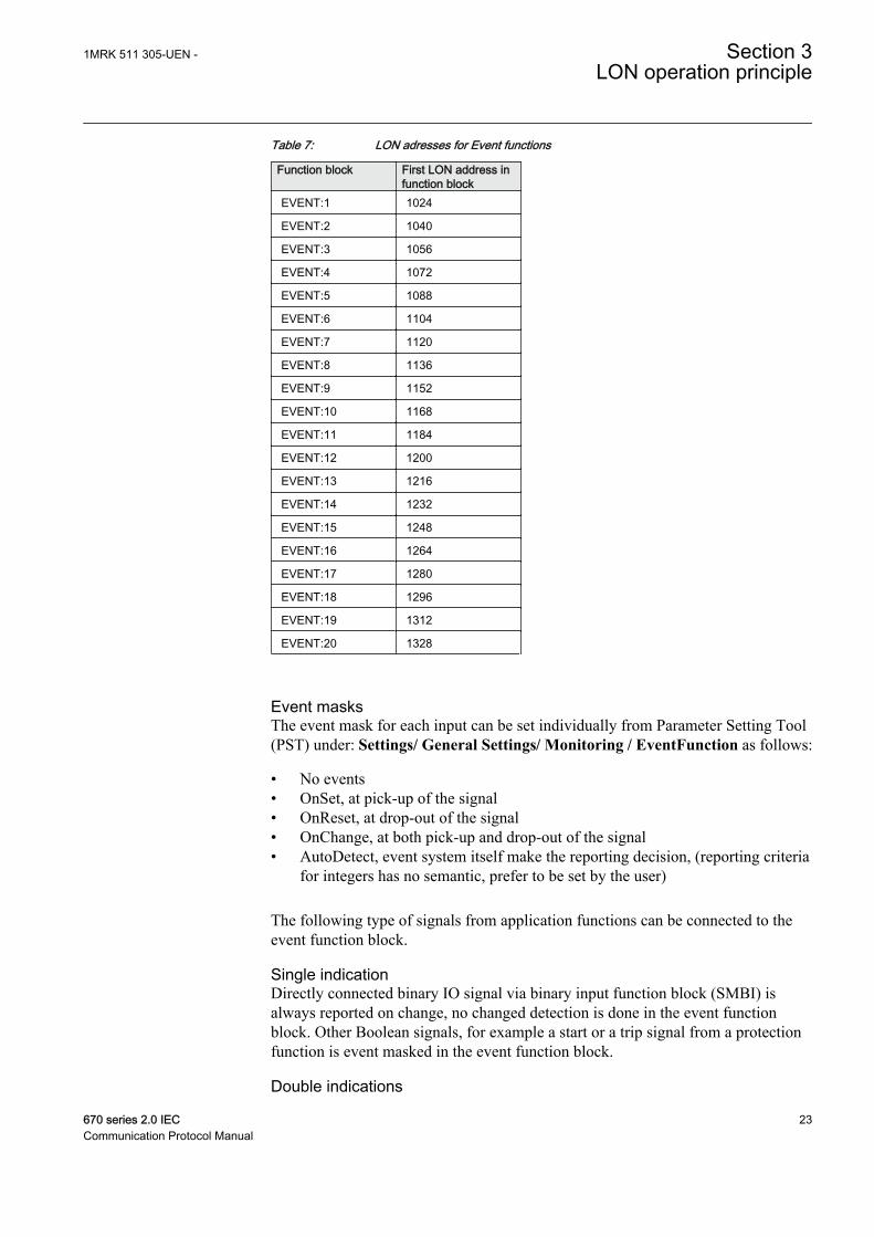
Table 7: LON adresses for Event functions
Function block First LON address infunction block
EVENT:1 1024
EVENT:2 1040
EVENT:3 1056
EVENT:4 1072
EVENT:5 1088
EVENT:6 1104
EVENT:7 1120
EVENT:8 1136
EVENT:9 1152
EVENT:10 1168
EVENT:11 1184
EVENT:12 1200
EVENT:13 1216
EVENT:14 1232
EVENT:15 1248
EVENT:16 1264
EVENT:17 1280
EVENT:18 1296
EVENT:19 1312
EVENT:20 1328
Event masksThe event mask for each input can be set individually from Parameter Setting Tool(PST) under: Settings/ General Settings/ Monitoring / EventFunction as follows:
• No events• OnSet, at pick-up of the signal• OnReset, at drop-out of the signal• OnChange, at both pick-up and drop-out of the signal• AutoDetect, event system itself make the reporting decision, (reporting criteria
for integers has no semantic, prefer to be set by the user)
The following type of signals from application functions can be connected to theevent function block.
Single indicationDirectly connected binary IO signal via binary input function block (SMBI) isalways reported on change, no changed detection is done in the event functionblock. Other Boolean signals, for example a start or a trip signal from a protectionfunction is event masked in the event function block.
Double indications
1MRK 511 305-UEN - Section 3LON operation principle
670 series 2.0 IEC 23Communication Protocol Manual

Double indications can only be reported via switch-control (SCSWI) functions, theevent reporting is based on information from switch-control, no change detection isdone in the event function block.
Directly connected binary IO signal via binary input function block (SMBI) is notpossible to handle as double indication. Double indications can only be reported forthe first 8 inputs on an event function block.
• 00 generates an intermediate event with the read status 0• 01 generates an open event with the read status 1• 10 generates a close event with the read status 2• 11 generates an undefined event with the read status 3
Analog valueAll analog values are reported cyclic. The reporting interval is taken from theconnected function if there is a limit supervised signal, otherwise it is taken fromthe event function block.
Command handlingCommands are transferred using transparent SPA-bus messages. The transparentSPA-bus message is an explicit LON message, which contains an ASCII charactermessage following the coding rules of the SPA-bus protocol. The message is sentusing explicit messages with message code 41H and using acknowledged transportservice.
Both the SPA-bus command messages (R or W) and the reply messages (D, A orN) are sent using the same message code. It is mandatory that one device sends outonly one SPA-bus message at a time to one node and waits for the reply beforesending the next message.
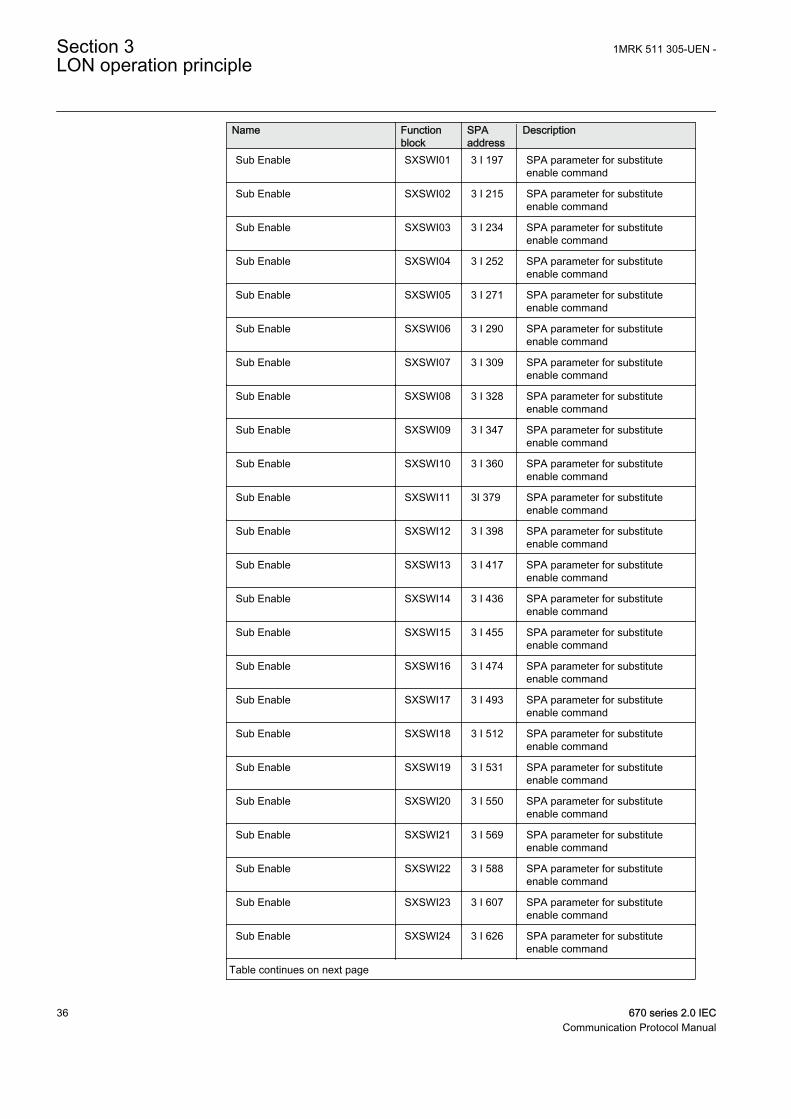
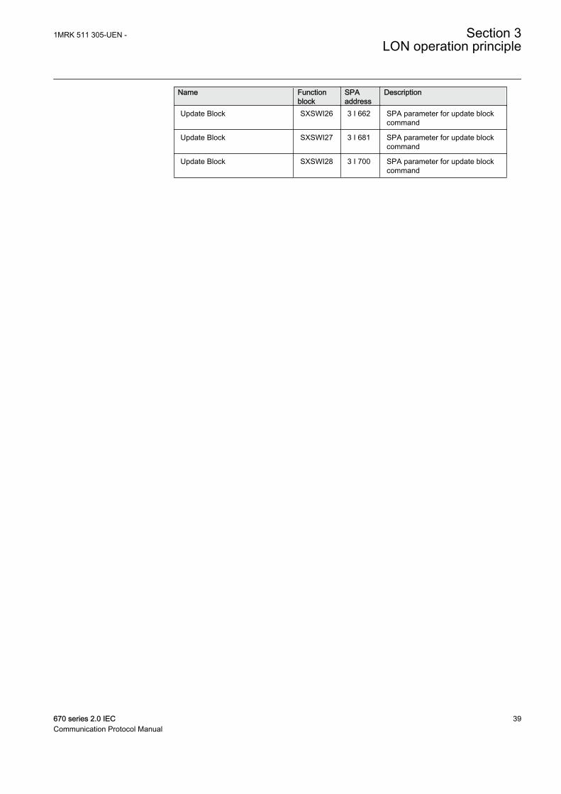
For commands from the operator workplace to the IED for apparatus control, Thatis, the function blocks type SCSWI 1 to 32, SXCBR 1 to 18 and SXSWI 1 to 28;the SPA addresses are according to table 8.
3.1.1.2 Horizontal communication
Network variables are used for communication between 500 series and 670 seriesIEDs. The supported network variable type is SNVT_state (NV type 83).SNVT_state is used to communicate the state of a set of 1 to 16 Boolean values.
Multiple command send function block (MULTICMDSND) is used to pack theinformation to one value. This value is transmitted to the receiving node andpresented for the application by a multiple command receive function block(MULTICMDRCV). At horizontal communication the input BOUND on themultiple command send function block (MULTICMDSND) must be set to 1. Thereare 10 MULTICMDSND and 60 MULTICMDRCV function blocks available. TheMULTICMDSND and MULTICMDRCV function blocks are connected usingLON network tool (LNT). This tool also defines the service and addressing on LON.
Section 3 1MRK 511 305-UEN -LON operation principle
24 670 series 2.0 IECCommunication Protocol Manual

This is an overview for configuring the network variables for 670 series IEDs.
Configuration of LON network variablesConfigure the Network variables according to the specific application using theLON network tool (LNT). The following is an example of how to configurenetwork variables concerning, for example, interlocking between two IEDs.
MULTICMDSND: 7 BAY E1
MULTICMDSND: 9 BAY E3
LON
BAY E4
MULTICMDSND: 9
en05000718.vsdIEC05000718 V2 EN
Figure 3: Examples connections between MULTICMDSND andMULTICMDRCV function blocks in three IEDs
The network variable connections are done from the NV Connection window.From LNT window select Connections/ NVConnections/ New.
1MRK 511 305-UEN - Section 3LON operation principle
670 series 2.0 IEC 25Communication Protocol Manual

en05000719.vsdIEC05000719 V1 EN
Figure 4: The network variables window in LNT
There are two ways of downloading NV connections. Either the users can use thedrag-and-drop method where they can select all nodes in the device window, dragthem to the Download area in the bottom of the program window and drop themthere; or, they can perform it by selecting the traditional menu, Configuration/Download.
Section 3 1MRK 511 305-UEN -LON operation principle
26 670 series 2.0 IECCommunication Protocol Manual

en05000720.vsdIEC05000720 V1 EN
Figure 5: The download configuration window in LNT
3.1.1.3 Communication ports
The serial communication module (SLM) is a mezzanine module placed on theMain Processing Module (NUM) and is used for LON, SPA, IEC60870-5-103 andDNP communication.
There are two types of IO connectors: 1) snap-in for plastic fibre cables, and 2) ST/bayonet for glass fibre cables. The SLM can be equipped with either type or acombination of both, which is identified by a tag.
Connect the incoming optical fibre to the RX receiver input, and the outgoingoptical fibre to the TX transmitter output. Pay special attention to the instructionsconcerning handling and connection of fibre cables.
Table 8: SPA addresses for commands from the operator workplace to the IED for apparatuscontrol
Name Functionblock
SPAaddress
Description
BL_CMD SCSWI01 1 I 5115 SPA parameters for blockcommand
BL_CMD SCSWI02 1 I 5139 SPA parameters for blockcommand
BL_CMD SCSWI02 1 I 5161 SPA parameters for blockcommand
BL_CMD SCSWI04 1 I 5186 SPA parameters for blockcommand
BL_CMD SCSWI05 1 I 5210 SPA parameters for blockcommand
Table continues on next page
1MRK 511 305-UEN - Section 3LON operation principle
670 series 2.0 IEC 27Communication Protocol Manual

Name Functionblock
SPAaddress
Description
BL_CMD SCSWI06 1 I 5234 SPA parameters for blockcommand
BL_CMD SCSWI07 1 I 5258 SPA parameters for blockcommand
BL_CMD SCSWI08 1 I 5283 SPA parameters for blockcommand
BL_CMD SCSWI09 1 I 5307 SPA parameters for blockcommand
BL_CMD SCSWI10 1 I 5331 SPA parameters for blockcommand
BL_CMD SCSWI11 1 I 5355 SPA parameters for blockcommand
BL_CMD SCSWI12 1 I 5379 SPA parameters for blockcommand
BL_CMD SCSWI13 1 I 5403 SPA parameters for blockcommand
BL_CMD SCSWI14 1 I 5427 SPA parameters for blockcommand
BL_CMD SCSWI15 1 I 5451 SPA parameters for blockcommand
BL_CMD SCSWI16 1 I 5475 SPA parameters for blockcommand
BL_CMD SCSWI17 1 I 5499 SPA parameters for blockcommand
BL_CMD SCSWI18 1 I 5523 SPA parameters for blockcommand
BL_CMD SCSWI19 1 I 5545 SPA parameters for blockcommand
BL_CMD SCSWI20 1 I 5571 SPA parameters for blockcommand
BL_CMD SCSWI21 1 I 5594 SPA parameters for blockcommand
BL_CMD SCSWI22 1 I 5619 SPA parameters for blockcommand
BL_CMD SCSWI23 1 I 5643 SPA parameters for blockcommand
BL_CMD SCSWI24 1 I 5667 SPA parameters for blockcommand
BL_CMD SCSWI25 1 I 5691 SPA parameters for blockcommand
BL_CMD SCSWI26 1 I 5715 SPA parameters for blockcommand
BL_CMD SCSWI27 1 I 5739 SPA parameters for blockcommand
BL_CMD SCSWI28 1 I 5763 SPA parameters for blockcommand
BL_CMD SCSWI29 1 I 5787 SPA parameters for blockcommand
Table continues on next page
Section 3 1MRK 511 305-UEN -LON operation principle
28 670 series 2.0 IECCommunication Protocol Manual

Name Functionblock
SPAaddress
Description
BL_CMD SCSWI30 1 I 5811 SPA parameters for blockcommand
BL_CMD SCSWI31 1 I 5835 SPA parameters for blockcommand
BL_CMD SCSWI32 1 I 5859 SPA parameters for blockcommand
CANCEL SCSWI01 1 I 5107 SPA parameters for cancelcommand
CANCEL SCSWI02 1 I 5131 SPA parameters for cancelcommand
CANCEL SCSWI03 1 I 5153 SPA parameters for cancelcommand
CANCEL SCSWI04 1 I 5178 SPA parameters for cancelcommand
CANCEL SCSWI05 1 I 5202 SPA parameters for cancelcommand
CANCEL SCSWI06 1 I 5226 SPA parameters for cancelcommand
CANCEL SCSWI07 1 I 5250 SPA parameters for cancelcommand
CANCEL SCSWI08 1 I 5275 SPA parameters for cancelcommand
CANCEL SCSWI09 1 I 5299 SPA parameters for cancelcommand
CANCEL SCSWI10 1 I 5323 SPA parameters for cancelcommand
CANCEL SCSWI11 1 I 5347 SPA parameters for cancelcommand
CANCEL SCSWI12 1 I 5371 SPA parameters for cancelcommand
CANCEL SCSWI13 1 I 5395 SPA parameters for cancelcommand
CANCEL SCSWI14 1 I 5419 SPA parameters for cancelcommand
CANCEL SCSWI15 1 I 5443 SPA parameters for cancelcommand
CANCEL SCSWI16 1 I 5467 SPA parameters for cancelcommand
CANCEL SCSWI17 1 I 5491 SPA parameters for cancelcommand
CANCEL SCSWI18 1 I 5515 SPA parameters for cancelcommand
CANCEL SCSWI19 1 I 5537 SPA parameters for cancelcommand
CANCEL SCSWI20 1 I 5563 SPA parameters for cancelcommand
CANCEL SCSWI21 1 I 5586 SPA parameters for cancelcommand
Table continues on next page
1MRK 511 305-UEN - Section 3LON operation principle
670 series 2.0 IEC 29Communication Protocol Manual

Name Functionblock
SPAaddress
Description
CANCEL SCSWI22 1 I 5611 SPA parameters for cancelcommand
CANCEL SCSWI23 1 I 5635 SPA parameters for cancelcommand
CANCEL SCSWI24 1 I 5659 SPA parameters for cancelcommand
CANCEL SCSWI25 1 I 5683 SPA parameters for cancelcommand
CANCEL SCSWI26 1 I 5707 SPA parameters for cancelcommand
CANCEL SCSWI27 1 I 5731 SPA parameters for cancelcommand
CANCEL SCSWI28 1 I 5755 SPA parameters for cancelcommand
CANCEL SCSWI29 1 I 5779 SPA parameters for cancelcommand
CANCEL SCSWI30 1 I 5803 SPA parameters for cancelcommand
CANCEL SCSWI31 1 I 5827 SPA parameters for cancelcommand
CANCEL SCSWI32 1 I 5851 SPA parameters for cancelcommand
SELECTOpen=00,SELECTClose=01,SELOpen+ILO=10,SELClose+ILO=11,SELOpen+SCO=20,SELClose+SCO=21,SELOpen+ILO+SCO=30,SELClose+ILO+SCO=31
SCSWI01 1 I 5105 SPA parameters for select (Open/Close) commandNote: Send select commandbefore operate command
SELECTOpen=00,SELECTClose=01, so on.
SCSWI02 1 I 5129 SPA parameters for select (Open/Close) command
SELECTOpen=00,SELECTClose=01, so on.
SCSWI03 1 I 5151 SPA parameters for select (Open/Close) command
SELECTOpen=00,SELECTClose=01, so on.
SCSWI04 1 I 5176 SPA parameters for select (Open/Close) command
SELECTOpen=00,SELECTClose=01, so on.
SCSWI05 1 I 5200 SPA parameters for select (Open/Close) command
SELECTOpen=00,SELECTClose=01, so on.
SCSWI06 1 I 5224 SPA parameters for select (Open/Close) command
SELECTOpen=00,SELECTClose=01, so on.
SCSWI07 1 I 5248 SPA parameters for select (Open/Close) command
SELECTOpen=00,SELECTClose=01, so on.
SCSWI08 1 I 5273 SPA parameters for select (Open/Close) command
SELECTOpen=00,SELECTClose=01, so on.
SCSWI09 1 I 5297 SPA parameters for select (Open/Close) command
SELECTOpen=00,SELECTClose=01, so on.
SCSWI10 1 I 5321 SPA parameters for select (Open/Close) command
SELECTOpen=00,SELECTClose=01, so on.
SCSWI11 1 I 5345 SPA parameters for select (Open/Close) command
Table continues on next page
Section 3 1MRK 511 305-UEN -LON operation principle
30 670 series 2.0 IECCommunication Protocol Manual

Name Functionblock
SPAaddress
Description
SELECTOpen=00,SELECTClose=01, so on.
SCSWI12 1 I 5369 SPA parameters for select (Open/Close) command
SELECTOpen=00,SELECTClose=01, so on.
SCSWI13 1 I 5393 SPA parameters for select (Open/Close) command
SELECTOpen=00,SELECTClose=01, so on.
SCSWI14 1 I 5417 SPA parameters for select (Open/Close) command
SELECTOpen=00,SELECTClose=01, so on.
SCSWI15 1 I 5441 SPA parameters for select (Open/Close) command
SELECTOpen=00,SELECTClose=01, so on.
SCSWI16 1 I 5465 SPA parameters for select (Open/Close) command
SELECTOpen=00,SELECTClose=01, so on.
SCSWI17 1 I 5489 SPA parameters for select (Open/Close) command
SELECTOpen=00,SELECTClose=01, so on.
SCSWI18 1 I 5513 SPA parameters for select (Open/Close) command
SELECTOpen=00,SELECTClose=01, so on.
SCSWI19 1 I 5535 SPA parameters for select (Open/Close) command
SELECTOpen=00,SELECTClose=01, so on.
SCSWI20 1 I 5561 SPA parameters for select (Open/Close) command
SELECTOpen=00,SELECTClose=01, so on.
SCSWI21 1 I 5584 SPA parameters for select (Open/Close) command
SELECTOpen=00,SELECTClose=01, so on.
SCSWI22 1 I 5609 SPA parameters for select (Open/Close) command
SELECTOpen=00,SELECTClose=01, so on.
SCSWI23 1 I 5633 SPA parameters for select (Open/Close) command
SELECTOpen=00,SELECTClose=01, so on.
SCSWI24 1 I 5657 SPA parameters for select (Open/Close) command
SELECTOpen=00,SELECTClose=01, so on.
SCSWI25 1 I 5681 SPA parameters for select (Open/Close) command
SELECTOpen=00,SELECTClose=01, so on.
SCSWI26 1 I 5705 SPA parameters for select (Open/Close) command
SELECTOpen=00,SELECTClose=01, so on.
SCSWI27 1 I 5729 SPA parameters for select (Open/Close) command
SELECTOpen=00,SELECTClose=01, so on.
SCSWI28 1 I 5753 SPA parameters for select (Open/Close) command
SELECTOpen=00,SELECTClose=01, so on.
SCSWI29 1 I 5777 SPA parameters for select (Open/Close) command
SELECTOpen=00,SELECTClose=01, so on.
SCSWI30 1 I 5801 SPA parameters for select (Open/Close) command
SELECTOpen=00,SELECTClose=01, so on.
SCSWI31 1 I 5825 SPA parameters for select (Open/Close) command
SELECTOpen=00,SELECTClose=01, so on.
SCSWI32 1 I 5849 SPA parameters for select (Open/Close) command
ExcOpen=00,ExcClose=01,ExcOpen+ILO=10,ExcClose+ILO=11,ExcOpen+SCO=20,ExcClose+SCO=21,ExcOpen+ILO+SCO=30,ExcClose+ILO+SCO=31
SCSWI01 1 I 5106 SPA parameters for operate (Open/Close) commandNote: Send select commandbefore operate command
Table continues on next page
1MRK 511 305-UEN - Section 3LON operation principle
670 series 2.0 IEC 31Communication Protocol Manual

Name Functionblock
SPAaddress
Description
ExcOpen=00,ExcClose=01, so on.
SCSWI02 1 I 5130 SPA parameters for operate (Open/Close) command
ExcOpen=00,ExcClose=01, so on.
SCSWI02 1 I 5152 SPA parameters for operate (Open/Close) command
ExcOpen=00,ExcClose=01, so on.
SCSWI04 1 I 5177 SPA parameters for operate (Open/Close) command
ExcOpen=00,ExcClose=01, so on.
SCSWI05 1 I 5201 SPA parameters for operate (Open/Close) command
ExcOpen=00,ExcClose=01, so on.
SCSWI06 1 I 5225 SPA parameters for operate (Open/Close) command
ExcOpen=00,ExcClose=01, so on.
SCSWI07 1 I 5249 SPA parameters for operate (Open/Close) command
ExcOpen=00,ExcClose=01, so on.
SCSWI08 1 I 5274 SPA parameters for operate (Open/Close) command
ExcOpen=00,ExcClose=01, so on.
SCSWI09 1 I 5298 SPA parameters for operate (Open/Close) command
ExcOpen=00,ExcClose=01, so on.
SCSWI10 1 I 5322 SPA parameters for operate (Open/Close) command
ExcOpen=00,ExcClose=01, so on.
SCSWI11 1 I 5346 SPA parameters for operate (Open/Close) command
ExcOpen=00,ExcClose=01, so on.
SCSWI12 1 I 5370 SPA parameters for operate (Open/Close) command
ExcOpen=00,ExcClose=01, so on.
SCSWI13 1 I 5394 SPA parameters for operate (Open/Close) command
ExcOpen=00,ExcClose=01, so on.
SCSWI14 1 I 5418 SPA parameters for operate (Open/Close) command
ExcOpen=00,ExcClose=01, so on.
SCSWI15 1 I 5442 SPA parameters for operate (Open/Close) command
ExcOpen=00,ExcClose=01, so on.
SCSWI16 1 I 5466 SPA parameters for operate (Open/Close) command
ExcOpen=00,ExcClose=01, so on.
SCSWI17 1 I 5490 SPA parameters for operate (Open/Close) command
ExcOpen=00,ExcClose=01, so on.
SCSWI18 1 I 5514 SPA parameters for operate (Open/Close) command
ExcOpen=00,ExcClose=01, so on.
SCSWI19 1 I 5536 SPA parameters for operate (Open/Close) command
ExcOpen=00,ExcClose=01, so on.
SCSWI20 1 I 5562 SPA parameters for operate (Open/Close) command
ExcOpen=00,ExcClose=01, so on.
SCSWI21 1 I 5585 SPA parameters for operate (Open/Close) command
ExcOpen=00,ExcClose=01, so on.
SCSWI22 1 I 5610 SPA parameters for operate (Open/Close) command
ExcOpen=00,ExcClose=01, so on.
SCSWI23 1 I 5634 SPA parameters for operate (Open/Close) command
ExcOpen=00,ExcClose=01, so on.
SCSWI24 1 I 5658 SPA parameters for operate (Open/Close) command
ExcOpen=00,ExcClose=01, so on.
SCSWI25 1 I 5682 SPA parameters for operate (Open/Close) command
Table continues on next page
Section 3 1MRK 511 305-UEN -LON operation principle
32 670 series 2.0 IECCommunication Protocol Manual

Name Functionblock
SPAaddress
Description
ExcOpen=00,ExcClose=01, so on.
SCSWI26 1 I 5706 SPA parameters for operate (Open/Close) command
ExcOpen=00,ExcClose=01, so on.
SCSWI27 1 I 5730 SPA parameters for operate (Open/Close) command
ExcOpen=00,ExcClose=01, so on.
SCSWI28 1 I 5754 SPA parameters for operate (Open/Close) command
ExcOpen=00,ExcClose=01, so on.
SCSWI29 1 I 5778 SPA parameters for operate (Open/Close) command
ExcOpen=00,ExcClose=01, so on.
SCSWI30 1 I 5802 SPA parameters for operate (Open/Close) command
ExcOpen=00,ExcClose=01, so on.
SCSWI31 1 I 5826 SPA parameters for operate (Open/Close) command
ExcOpen=00,ExcClose=01, so on.
SCSWI32 1 I 5850 SPA parameters for operate (Open/Close) command
Sub Value SXCBR01 2 I 7854 SPA parameter for position to besubstitutedNote: Send the value before Enable
Sub Value SXCBR02 2 I 7866 SPA parameter for position to besubstituted
Sub Value SXCBR03 2 I 7884 SPA parameter for position to besubstituted
Sub Value SXCBR04 2 I 7904 SPA parameter for position to besubstituted
Sub Value SXCBR05 2 I 7923 SPA parameter for position to besubstituted
Sub Value SXCBR06 2 I 7942 SPA parameter for position to besubstituted
Sub Value SXCBR07 2 I 7961 SPA parameter for position to besubstituted
Sub Value SXCBR08 2 I 7980 SPA parameter for position to besubstituted
Sub Value SXCBR09 3 I 7 SPA parameter for position to besubstituted
Sub Value SXCBR10 3 I 26 SPA parameter for position to besubstituted
Sub Value SXCBR11 3 I 45 SPA parameter for position to besubstituted
Sub Value SXCBR12 3 I 56 SPA parameter for position to besubstituted
Sub Value SXCBR13 3 I 74 SPA parameter for position to besubstituted
Sub Value SXCBR14 3 I 94 SPA parameter for position to besubstituted
Sub Value SXCBR15 3 I 120 SPA parameter for position to besubstituted
Sub Value SXCBR16 3 I 133 SPA parameter for position to besubstituted
Sub Value SXCBR17 3 I 158 SPA parameter for position to besubstituted
Table continues on next page
1MRK 511 305-UEN - Section 3LON operation principle
670 series 2.0 IEC 33Communication Protocol Manual

Name Functionblock
SPAaddress
Description
Sub Value SXCBR18 3 I 179 SPA parameter for position to besubstituted
Sub Value SXSWI01 3 I 196 SPA parameter for position to besubstituted
Sub Value SXSWI02 3 I 216 SPA parameter for position to besubstituted
Sub Value SXSWI03 3 I 235 SPA parameter for position to besubstituted
Sub Value SXSWI04 3 I 254 SPA parameter for position to besubstituted
Sub Value SXSWI05 3 I 272 SPA parameter for position to besubstituted
Sub Value SXSWI06 3 I 292 SPA parameter for position to besubstituted
Sub Value SXSWI07 3 I 310 SPA parameter for position to besubstituted
Sub Value SXSWI08 3 I 330 SPA parameter for position to besubstituted
Sub Value SXSWI09 3 I 348 SPA parameter for position to besubstituted
Sub Value SXSWI10 3 I 359 SPA parameter for position to besubstituted
Sub Value SXSWI11 3 I 378 SPA parameter for position to besubstituted
Sub Value SXSWI12 3 I 397 SPA parameter for position to besubstituted
Sub Value SXSWI13 3 I 416 SPA parameter for position to besubstituted
Sub Value SXSWI14 3 I 435 SPA parameter for position to besubstituted
Sub Value SXSWI15 3 I 454 SPA parameter for position to besubstituted
Sub Value SXSWI16 3 I 473 SPA parameter for position to besubstituted
Sub Value SXSWI17 3 I 492 SPA parameter for position to besubstituted
Sub Value SXSWI18 3 I 511 SPA parameter for position to besubstituted
Sub Value SXSWI19 3 I 530 SPA parameter for position to besubstituted
Sub Value SXSWI20 3 I 549 SPA parameter for position to besubstituted
Sub Value SXSWI21 3 I 568 SPA parameter for position to besubstituted
Sub Value SXSWI22 3 I 587 SPA parameter for position to besubstituted
Sub Value SXSWI23 3 I 606 SPA parameter for position to besubstituted
Table continues on next page
Section 3 1MRK 511 305-UEN -LON operation principle
34 670 series 2.0 IECCommunication Protocol Manual

Name Functionblock
SPAaddress
Description
Sub Value SXSWI24 3 I 625 SPA parameter for position to besubstituted
Sub Value SXSWI25 3 I 644 SPA parameter for position to besubstituted
Sub Value SXSWI26 3 I 663 SPA parameter for position to besubstituted
Sub Value SXSWI27 3 I 682 SPA parameter for position to besubstituted
Sub Value SXSWI28 3 I 701 SPA parameter for position to besubstituted
Sub Enable SXCBR01 2 I 7855 SPA parameter for substituteenable commandNote: Send the Value beforeEnable
Sub Enable SXCBR02 2 I 7865 SPA parameter for substituteenable command
Sub Enable SXCBR03 2 I 7885 SPA parameter for substituteenable command
Sub Enable SXCBR04 2 I 7903 SPA parameter for substituteenable command
Sub Enable SXCBR05 2 I 7924 SPA parameter for substituteenable command
Sub Enable SXCBR06 2 I 7941 SPA parameter for substituteenable command
Sub Enable SXCBR07 2 I 7962 SPA parameter for substituteenable command
Sub Enable SXCBR08 2 I 7979 SPA parameter for substituteenable command
Sub Enable SXCBR09 3 I 8 SPA parameter for substituteenable command
Sub Enable SXCBR10 3 I 25 SPA parameter for substituteenable command
Sub Enable SXCBR11 3 I 46 SPA parameter for substituteenable command
Sub Enable SXCBR12 3 I 55 SPA parameter for substituteenable command
Sub Enable SXCBR13 3 I 75 SPA parameter for substituteenable command
Sub Enable SXCBR14 3 I 93 SPA parameter for substituteenable command
Sub Enable SXCBR15 3 I 121 SPA parameter for substituteenable command
Sub Enable SXCBR16 3 I 132 SPA parameter for substituteenable command
Sub Enable SXCBR17 3 I 159 SPA parameter for substituteenable command
Sub Enable SXCBR18 3 I 178 SPA parameter for substituteenable command
Table continues on next page
1MRK 511 305-UEN - Section 3LON operation principle
670 series 2.0 IEC 35Communication Protocol Manual
Name Functionblock
SPAaddress
Description
Sub Enable SXSWI01 3 I 197 SPA parameter for substituteenable command
Sub Enable SXSWI02 3 I 215 SPA parameter for substituteenable command
Sub Enable SXSWI03 3 I 234 SPA parameter for substituteenable command
Sub Enable SXSWI04 3 I 252 SPA parameter for substituteenable command
Sub Enable SXSWI05 3 I 271 SPA parameter for substituteenable command
Sub Enable SXSWI06 3 I 290 SPA parameter for substituteenable command
Sub Enable SXSWI07 3 I 309 SPA parameter for substituteenable command
Sub Enable SXSWI08 3 I 328 SPA parameter for substituteenable command
Sub Enable SXSWI09 3 I 347 SPA parameter for substituteenable command
Sub Enable SXSWI10 3 I 360 SPA parameter for substituteenable command
Sub Enable SXSWI11 3I 379 SPA parameter for substituteenable command
Sub Enable SXSWI12 3 I 398 SPA parameter for substituteenable command
Sub Enable SXSWI13 3 I 417 SPA parameter for substituteenable command
Sub Enable SXSWI14 3 I 436 SPA parameter for substituteenable command
Sub Enable SXSWI15 3 I 455 SPA parameter for substituteenable command
Sub Enable SXSWI16 3 I 474 SPA parameter for substituteenable command
Sub Enable SXSWI17 3 I 493 SPA parameter for substituteenable command
Sub Enable SXSWI18 3 I 512 SPA parameter for substituteenable command
Sub Enable SXSWI19 3 I 531 SPA parameter for substituteenable command
Sub Enable SXSWI20 3 I 550 SPA parameter for substituteenable command
Sub Enable SXSWI21 3 I 569 SPA parameter for substituteenable command
Sub Enable SXSWI22 3 I 588 SPA parameter for substituteenable command
Sub Enable SXSWI23 3 I 607 SPA parameter for substituteenable command
Sub Enable SXSWI24 3 I 626 SPA parameter for substituteenable command
Table continues on next page
Section 3 1MRK 511 305-UEN -LON operation principle
36 670 series 2.0 IECCommunication Protocol Manual

Name Functionblock
SPAaddress
Description
Sub Enable SXSWI25 3 I 645 SPA parameter for substituteenable command
Sub Enable SXSWI26 3 I 664 SPA parameter for substituteenable command
Sub Enable SXSWI27 3 I 683 SPA parameter for substituteenable command
Sub Enable SXSWI28 3 I 702 SPA parameter for substituteenable command
Update Block SXCBR01 2 I 7853 SPA parameter for update blockcommand
Update Block SXCBR02 2 I 7864 SPA parameter for update blockcommand
Update Block SXCBR03 2 I 7883 SPA parameter for update blockcommand
Update Block SXCBR04 2 I 7905 SPA parameter for update blockcommand
Update Block SXCBR05 2 I 7922 SPA parameter for update blockcommand
Update Block SXCBR06 2 I 7943 SPA parameter for update blockcommand
Update Block SXCBR07 2 I 7960 SPA parameter for update blockcommand
Update Block SXCBR08 2 I 7981 SPA parameter for update blockcommand
Update Block SXCBR09 3 I 6 SPA parameter for update blockcommand
Update Block SXCBR10 3 I 27 SPA parameter for update blockcommand
Update Block SXCBR11 3 I 44 SPA parameter for update blockcommand
Update Block SXCBR12 3 I 57 SPA parameter for update blockcommand
Update Block SXCBR13 3 I 73 SPA parameter for update blockcommand
Update Block SXCBR14 3 I 92 SPA parameter for update blockcommand
Update Block SXCBR15 3 I 122 SPA parameter for update blockcommand
Update Block SXCBR16 3 I 131 SPA parameter for update blockcommand
Update Block SXCBR17 3 I 160 SPA parameter for update blockcommand
Update Block SXCBR18 3 I 177 SPA parameter for update blockcommand
Update Block SXSWI01 3 I 198 SPA parameter for update blockcommand
Update Block SXSWI02 3 I 214 SPA parameter for update blockcommand
Table continues on next page
1MRK 511 305-UEN - Section 3LON operation principle
670 series 2.0 IEC 37Communication Protocol Manual

Name Functionblock
SPAaddress
Description
Update Block SXSWI03 3 I 236 SPA parameter for update blockcommand
Update Block SXSWI04 3 I 253 SPA parameter for update blockcommand
Update Block SXSWI05 3 I 273 SPA parameter for update blockcommand
Update Block SXSWI06 3 I 291 SPA parameter for update blockcommand
Update Block SXSWI07 3 I 311 SPA parameter for update blockcommand
Update Block SXSWI08 3 I 329 SPA parameter for update blockcommand
Update Block SXSWI09 3 I 349 SPA parameter for update blockcommand
Update Block SXSWI10 3 I 358 SPA parameter for update blockcommand
Update Block SXSWI11 3 I 377 SPA parameter for update blockcommand
Update Block SXSWI12 3 I 396 SPA parameter for update blockcommand
Update Block SXSWI13 3 I 415 SPA parameter for update blockcommand
Update Block SXSWI14 3 I 434 SPA parameter for update blockcommand
Update Block SXSWI15 3 I 453 SPA parameter for update blockcommand
Update Block SXSWI16 3 I 472 SPA parameter for update blockcommand
Update Block SXSWI17 3 I 491 SPA parameter for update blockcommand
Update Block SXSWI18 3 I 510 SPA parameter for update blockcommand
Update Block SXSWI19 3 I 529 SPA parameter for update blockcommand
Update Block SXSWI20 3 I 548 SPA parameter for update blockcommand
Update Block SXSWI21 3 I 567 SPA parameter for update blockcommand
Update Block SXSWI22 3 I 586 SPA parameter for update blockcommand
Update Block SXSWI23 3 I 605 SPA parameter for update blockcommand
Update Block SXSWI24 3 I 624 SPA parameter for update blockcommand
Update Block SXSWI25 3 I 643 SPA parameter for update blockcommand
Table continues on next page
Section 3 1MRK 511 305-UEN -LON operation principle
38 670 series 2.0 IECCommunication Protocol Manual
Name Functionblock
SPAaddress
Description
Update Block SXSWI26 3 I 662 SPA parameter for update blockcommand
Update Block SXSWI27 3 I 681 SPA parameter for update blockcommand
Update Block SXSWI28 3 I 700 SPA parameter for update blockcommand
1MRK 511 305-UEN - Section 3LON operation principle
670 series 2.0 IEC 39Communication Protocol Manual

40
Section 4 LON settings
4.1 Settings
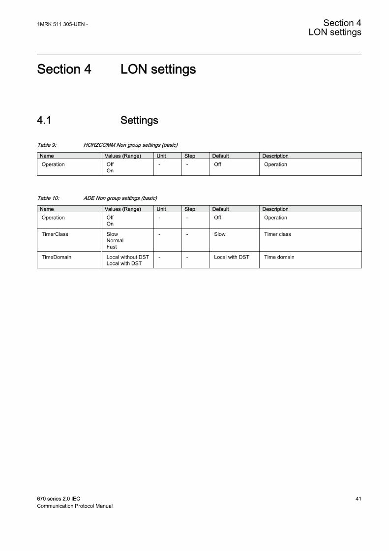
Table 9: HORZCOMM Non group settings (basic)
Name Values (Range) Unit Step Default DescriptionOperation Off
On- - Off Operation
Table 10: ADE Non group settings (basic)
Name Values (Range) Unit Step Default DescriptionOperation Off
On- - Off Operation
TimerClass SlowNormalFast
- - Slow Timer class
TimeDomain Local without DSTLocal with DST
- - Local with DST Time domain
1MRK 511 305-UEN - Section 4LON settings
670 series 2.0 IEC 41Communication Protocol Manual

42

Section 5 LON technical data
5.1 Technical data
Table 11: LON communication protocol
Function ValueProtocol LON
Communication speed 1.25 Mbit/s
1MRK 511 305-UEN - Section 5LON technical data
670 series 2.0 IEC 43Communication Protocol Manual

44

Section 6 Establishing connection and verifyingthe LON communication
6.1 Establishing connection and verifying the LONcommunication
About this chapterThis chapter explains how to set up LON communication and how to verify thatLON communication is up and running.
6.1.1 Communication via the rear ports
6.1.1.1 LON communication
LON communication is normally used in substation automation systems. Opticalfiber is used within the substation as the physical communication link.
The test can only be carried out when the whole communication system is installed.Thus, the test is a system test and is not dealt with here.
The communication protocol Local Optical Network (LON) is available for 670IED series.
6.1.2 SettingsThe setting parameters for the LON communication are set via the local HMI.Refer to the technical manual for setting parameters specifications.
The path to LON settings in the local HMI is Main menu/Configuration/Communication/SLM configuration/Rear optical LON port
If the LON communication from the IED stops, caused by setting of illegalcommunication parameters (outside the setting range) or by another disturbance, itis possible to reset the LON port of the IED.
Path in the local HMI under Main menu/Configuration/Communication/SLMconfiguration/Rear optical LON port
These parameters can only be set with the LON Network Tool (LNT).
1MRK 511 305-UEN - Section 6Establishing connection and verifying the LON communication
670 series 2.0 IEC 45Communication Protocol Manual

Table 12: Setting parameters for the LON communication
Parameter Range Default Unit Parameter descriptionDomainID 0 0 - Domain identification number
SubnetID* 0 - 255Step: 1
0 - Subnet identification number
NodeID* 0 - 127Step: 1
0 - Node identification number
*Can be viewed in the local HMI
Path in the local HMI under Main menu/Congifuration/Communication/SLMconfiguration/Rear optical LON port
These parameters can only be set with the LON Network Tool (LNT).
Table 13: LON node information parameters
Parameter Range Default Unit Parameter descriptionNeuronID* 0 - 12 Not loaded - Neuron hardware identification
number in hexadecimal code
Location 0 - 6 No value - Location of the node
*Can be viewed in the local HMI
Path in the local HMI under Main menu/Configuration/Communication/SLMconfiguration/Rear optical LON port
Table 14: ADE Non group settings (basic)
Name Values (Range) Unit Step Default DescriptionOperation Off
On- - Off Operation
TimerClass SlowNormalFast
- - Slow Timer class
Path in the local HMI under Main menu/Configuration/Communication/SLMconfiguration/Rear optical LON port
Table 15: LON commands
Command Command descriptionServicePinMsg Command with confirmation. Transfers the node address to the LON Network Tool.
Section 6 1MRK 511 305-UEN -Establishing connection and verifying the LON communication
46 670 series 2.0 IECCommunication Protocol Manual

6.1.2.1 Optical budget calculation for serial communication with LON
Table 16: Example
Distance 1 kmGlass
Distance10 mPlastic
Maximum attenuation -11 dB - 7 dB
4 dB/km multi mode: 820 nm - 62.5/125 um 4 dB -
0.3 dB/m plastic: 620 nm - 1mm - 3 dB
Margins for installation, aging, and so on 5 dB 2 dB
Losses in connection box, two contacts (0.75 dB/contact) 1.5 dB -
Losses in connection box, two contacts (1dB/contact) - 2 dB
Margin for repair splices (0.5 dB/splice) 0.5 dB -
Maximum total attenuation 11 dB 7 dB
6.1.2.2 Reference
We refer to document: LNT 505 Operator’s Manual 1MRS751706-MUM, Issued:31.10.99, Program rev: 1.1.1 Doc. version: B.
1MRK 511 305-UEN - Section 6Establishing connection and verifying the LON communication
670 series 2.0 IEC 47Communication Protocol Manual

48

Section 7 LON Functions
7.1 Event function EVENT
7.1.1 IdentificationFunction description IEC 61850
identificationIEC 60617identification
ANSI/IEEE C37.2device number
Event function EVENTS00946 V1 EN
-
When using a Substation Automation system with LON or SPA communication,time-tagged events can be sent at change or cyclically from the IED to the stationlevel. These events are created from any available signal in the IED that isconnected to the Event function (EVENT). The event function block is used forLON and SPA communication.
Analog and double indication values are also transferred through EVENT function.
7.1.2 Function block
IEC05000697-2-en.vsd
EVENTBLOCK^INPUT1^INPUT2^INPUT3^INPUT4^INPUT5^INPUT6^INPUT7^INPUT8^INPUT9^INPUT10^INPUT11^INPUT12^INPUT13^INPUT14^INPUT15^INPUT16
IEC05000697 V2 EN
Figure 6: EVENT function block
1MRK 511 305-UEN - Section 7LON Functions
670 series 2.0 IEC 49Communication Protocol Manual

7.1.3 SignalsTable 17: EVENT Input signals
Name Type Default DescriptionBLOCK BOOLEAN 0 Block of function
INPUT1 GROUPSIGNAL
0 Input 1
INPUT2 GROUPSIGNAL
0 Input 2
INPUT3 GROUPSIGNAL
0 Input 3
INPUT4 GROUPSIGNAL
0 Input 4
INPUT5 GROUPSIGNAL
0 Input 5
INPUT6 GROUPSIGNAL
0 Input 6
INPUT7 GROUPSIGNAL
0 Input 7
INPUT8 GROUPSIGNAL
0 Input 8
INPUT9 GROUPSIGNAL
0 Input 9
INPUT10 GROUPSIGNAL
0 Input 10
INPUT11 GROUPSIGNAL
0 Input 11
INPUT12 GROUPSIGNAL
0 Input 12
INPUT13 GROUPSIGNAL
0 Input 13
INPUT14 GROUPSIGNAL
0 Input 14
INPUT15 GROUPSIGNAL
0 Input 15
INPUT16 GROUPSIGNAL
0 Input 16
Section 7 1MRK 511 305-UEN -LON Functions
50 670 series 2.0 IECCommunication Protocol Manual

7.1.4 SettingsTable 18: EVENT Non group settings (basic)
Name Values (Range) Unit Step Default DescriptionSPAChannelMask Off
Channel 1-8Channel 9-16Channel 1-16
- - Off SPA channel mask
LONChannelMask OffChannel 1-8Channel 9-16Channel 1-16
- - Off LON channel mask
EventMask1 NoEventsOnSetOnResetOnChangeAutoDetect
- - AutoDetect Reporting criteria for input 1
EventMask2 NoEventsOnSetOnResetOnChangeAutoDetect
- - AutoDetect Reporting criteria for input 2
EventMask3 NoEventsOnSetOnResetOnChangeAutoDetect
- - AutoDetect Reporting criteria for input 3
EventMask4 NoEventsOnSetOnResetOnChangeAutoDetect
- - AutoDetect Reporting criteria for input 4
EventMask5 NoEventsOnSetOnResetOnChangeAutoDetect
- - AutoDetect Reporting criteria for input 5
EventMask6 NoEventsOnSetOnResetOnChangeAutoDetect
- - AutoDetect Reporting criteria for input 6
EventMask7 NoEventsOnSetOnResetOnChangeAutoDetect
- - AutoDetect Reporting criteria for input 7
EventMask8 NoEventsOnSetOnResetOnChangeAutoDetect
- - AutoDetect Reporting criteria for input 8
EventMask9 NoEventsOnSetOnResetOnChangeAutoDetect
- - AutoDetect Reporting criteria for input 9
Table continues on next page
1MRK 511 305-UEN - Section 7LON Functions
670 series 2.0 IEC 51Communication Protocol Manual

Name Values (Range) Unit Step Default DescriptionEventMask10 NoEvents
OnSetOnResetOnChangeAutoDetect
- - AutoDetect Reporting criteria for input 10
EventMask11 NoEventsOnSetOnResetOnChangeAutoDetect
- - AutoDetect Reporting criteria for input 11
EventMask12 NoEventsOnSetOnResetOnChangeAutoDetect
- - AutoDetect Reporting criteria for input 12
EventMask13 NoEventsOnSetOnResetOnChangeAutoDetect
- - AutoDetect Reporting criteria for input 13
EventMask14 NoEventsOnSetOnResetOnChangeAutoDetect
- - AutoDetect Reporting criteria for input 14
EventMask15 NoEventsOnSetOnResetOnChangeAutoDetect
- - AutoDetect Reporting criteria for input 15
EventMask16 NoEventsOnSetOnResetOnChangeAutoDetect
- - AutoDetect Reporting criteria for input 16
MinRepIntVal1 0 - 3600 s 1 2 Minimum reporting interval input 1
MinRepIntVal2 0 - 3600 s 1 2 Minimum reporting interval input 2
MinRepIntVal3 0 - 3600 s 1 2 Minimum reporting interval input 3
MinRepIntVal4 0 - 3600 s 1 2 Minimum reporting interval input 4
MinRepIntVal5 0 - 3600 s 1 2 Minimum reporting interval input 5
MinRepIntVal6 0 - 3600 s 1 2 Minimum reporting interval input 6
MinRepIntVal7 0 - 3600 s 1 2 Minimum reporting interval input 7
MinRepIntVal8 0 - 3600 s 1 2 Minimum reporting interval input 8
MinRepIntVal9 0 - 3600 s 1 2 Minimum reporting interval input 9
MinRepIntVal10 0 - 3600 s 1 2 Minimum reporting interval input 10
MinRepIntVal11 0 - 3600 s 1 2 Minimum reporting interval input 11
MinRepIntVal12 0 - 3600 s 1 2 Minimum reporting interval input 12
MinRepIntVal13 0 - 3600 s 1 2 Minimum reporting interval input 13
Table continues on next page
Section 7 1MRK 511 305-UEN -LON Functions
52 670 series 2.0 IECCommunication Protocol Manual

Name Values (Range) Unit Step Default DescriptionMinRepIntVal14 0 - 3600 s 1 2 Minimum reporting interval input 14
MinRepIntVal15 0 - 3600 s 1 2 Minimum reporting interval input 15
MinRepIntVal16 0 - 3600 s 1 2 Minimum reporting interval input 16
7.1.5 Operation principleThe main purpose of the event function (EVENT) is to generate events when thestate or value of any of the connected input signals is in a state, or is undergoing astate transition, for which event generation is enabled.
Each EVENT function has 16 inputs INPUT1 - INPUT16. Each input can be givena name from the Application Configuration tool. The inputs are normally used tocreate single events, but are also intended for double indication events.
EVENT function also has an input BLOCK to block the generation of events.
The events that are sent from the IED can originate from both internal logicalsignals and binary input channels. The internal signals are time-tagged in the mainprocessing module, while the binary input channels are time-tagged directly on theinput module. The time-tagging of the events that are originated from internallogical signals have a resolution corresponding to the execution cyclicity ofEVENT function. The time-tagging of the events that are originated from binaryinput signals have a resolution of 1 ms.
The outputs from EVENT function are formed by the reading of status, events andalarms by the station level on every single input. The user-defined name for eachinput is intended to be used by the station level.
All events according to the event mask are stored in a buffer, which contains up to1000 events. If new events appear before the oldest event in the buffer is read, theoldest event is overwritten and an overflow alarm appears.
The events are produced according to the set-event masks. The event masks aretreated commonly for both the LON and SPA communication. The EventMask canbe set individually for each input channel. These settings are available:
• NoEvents• OnSet• OnReset• OnChange• AutoDetect
It is possible to define which part of EVENT function generates the events. Thiscan be performed individually for the SPAChannelMask and LONChannelMaskrespectively. For each communication type these settings are available:
1MRK 511 305-UEN - Section 7LON Functions
670 series 2.0 IEC 53Communication Protocol Manual

• Off• Channel 1-8• Channel 9-16• Channel 1-16
For LON communication the events normally are sent to station level at change. Itis possibly also to set a time for cyclic sending of the events individually for eachinput channel.
To protect the SA system from signals with a high change rate that can easilysaturate the event system or the communication subsystems behind it, a quotalimiter is implemented. If an input creates events at a rate that completely consumethe granted quota then further events from the channel will be blocked. This blockwill be removed when the input calms down and the accumulated quota reach 66%of the maximum burst quota. The maximum burst quota per input channel is 45events per second.
7.2 MULTICMDRCV and MULTICMDSND
Function description IEC 61850identification
IEC 60617identification
ANSI/IEEE C37.2device number
Multiple command and receive MULTICMDRCV - -
Multiple command and send MULTICMDSND - -
7.2.1 ApplicationThe IED provides two function blocks enabling several IEDs to send and receivesignals via the interbay bus. The sending function block, MULTICMDSND, takes16 binary inputs. LON enables these to be transmitted to the equivalent receivingfunction block, MULTICMDRCV, which has 16 binary outputs.
7.2.2 Design
7.2.2.1 General
The common behavior for all 16 outputs of the MULTICMDRCV is set to either oftwo modes: Steady or Pulse.
• 1 = Steady: This mode simply forwards the received signals to the binary outputs.• 2 = Pulse: When a received signal transitions from 0 (zero) to 1 (one), a pulse
with a duration of exactly one execution cycle is triggered on thecorresponding binary output. This means that no connected function blockmay have a cycle time that is higher than the execution cycle time of theparticular MULTICMDRCV instance.
Section 7 1MRK 511 305-UEN -LON Functions
54 670 series 2.0 IECCommunication Protocol Manual

7.2.3 Function block
IEC06000007-2-en.vsd
MULTICMDRCVBLOCK ERROR
NEWDATAOUTPUT1OUTPUT2OUTPUT3OUTPUT4OUTPUT5OUTPUT6OUTPUT7OUTPUT8OUTPUT9
OUTPUT10OUTPUT11OUTPUT12OUTPUT13OUTPUT14OUTPUT15OUTPUT16
VALID
IEC06000007 V2 EN
Figure 7: MULTICMDRCV function block
Table 19: MULTICMDRCV Input signals
Name Type Default DescriptionBLOCK BOOLEAN 0 Block of function
Table 20: MULTICMDRCV Output signals
Name Type DescriptionERROR BOOLEAN MultiReceive error
NEWDATA BOOLEAN New data is received
OUTPUT1 BOOLEAN Output 1
OUTPUT2 BOOLEAN Output 2
OUTPUT3 BOOLEAN Output 3
OUTPUT4 BOOLEAN Output 4
OUTPUT5 BOOLEAN Output 5
OUTPUT6 BOOLEAN Output 6
OUTPUT7 BOOLEAN Output 7
OUTPUT8 BOOLEAN Output 8
OUTPUT9 BOOLEAN Output 9
OUTPUT10 BOOLEAN Output 10
OUTPUT11 BOOLEAN Output 11
OUTPUT12 BOOLEAN Output 12
OUTPUT13 BOOLEAN Output 13
OUTPUT14 BOOLEAN Output 14
OUTPUT15 BOOLEAN Output 15
OUTPUT16 BOOLEAN Output 16
VALID BOOLEAN Output data is valid
1MRK 511 305-UEN - Section 7LON Functions
670 series 2.0 IEC 55Communication Protocol Manual
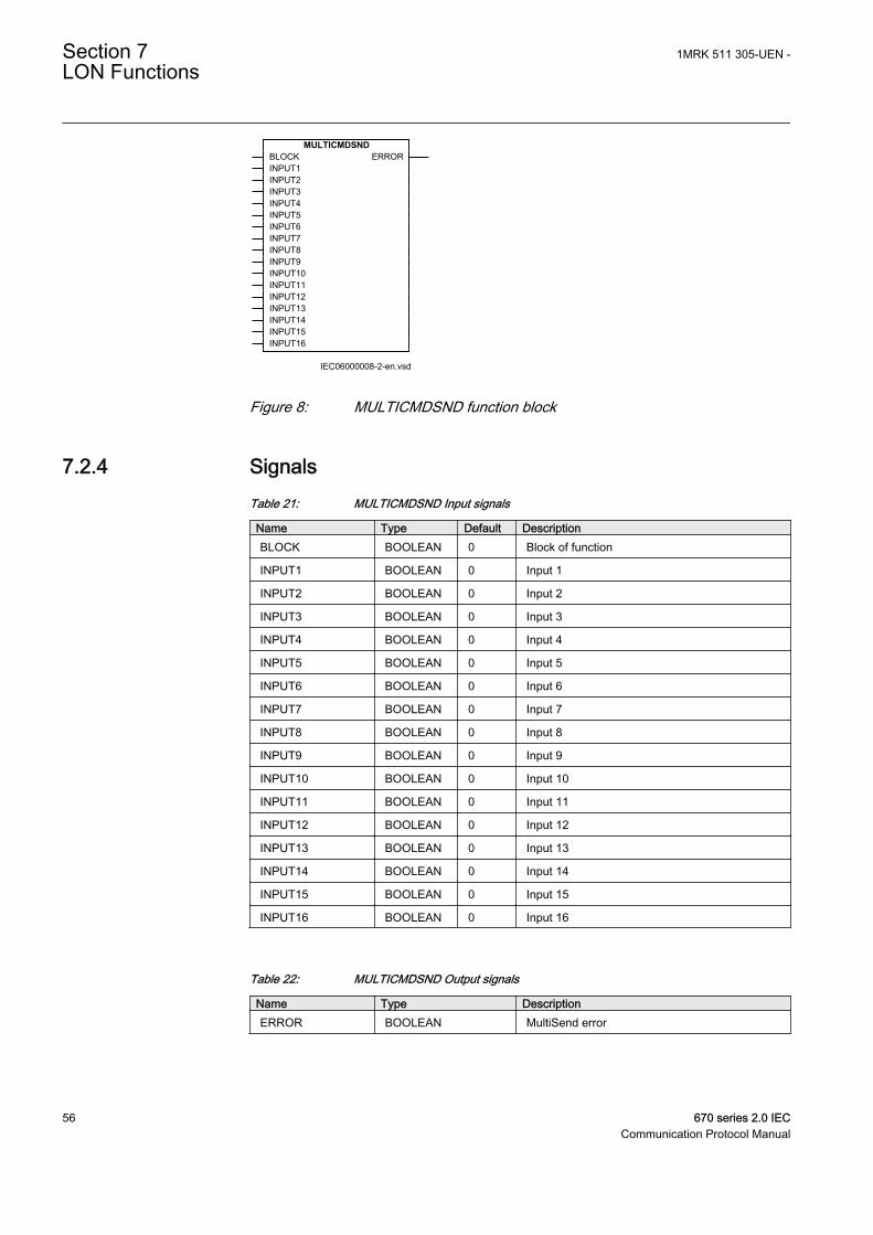
IEC06000008-2-en.vsd
MULTICMDSNDBLOCKINPUT1INPUT2INPUT3INPUT4INPUT5INPUT6INPUT7INPUT8INPUT9INPUT10INPUT11INPUT12INPUT13INPUT14INPUT15INPUT16
ERROR
IEC06000008 V2 EN
Figure 8: MULTICMDSND function block
7.2.4 SignalsTable 21: MULTICMDSND Input signals
Name Type Default DescriptionBLOCK BOOLEAN 0 Block of function
INPUT1 BOOLEAN 0 Input 1
INPUT2 BOOLEAN 0 Input 2
INPUT3 BOOLEAN 0 Input 3
INPUT4 BOOLEAN 0 Input 4
INPUT5 BOOLEAN 0 Input 5
INPUT6 BOOLEAN 0 Input 6
INPUT7 BOOLEAN 0 Input 7
INPUT8 BOOLEAN 0 Input 8
INPUT9 BOOLEAN 0 Input 9
INPUT10 BOOLEAN 0 Input 10
INPUT11 BOOLEAN 0 Input 11
INPUT12 BOOLEAN 0 Input 12
INPUT13 BOOLEAN 0 Input 13
INPUT14 BOOLEAN 0 Input 14
INPUT15 BOOLEAN 0 Input 15
INPUT16 BOOLEAN 0 Input 16
Table 22: MULTICMDSND Output signals
Name Type DescriptionERROR BOOLEAN MultiSend error
Section 7 1MRK 511 305-UEN -LON Functions
56 670 series 2.0 IECCommunication Protocol Manual

7.2.5 SettingsTable 23: MULTICMDRCV Non group settings (basic)
Name Values (Range) Unit Step Default DescriptiontMaxCycleTime 0.050 - 200.000 s 0.001 11.000 Maximum cycle time between receptions
of input data
tMinCycleTime 0.000 - 200.000 s 0.001 0.000 Minimum cycle time between receptionsof input data
Mode SteadyPulsed
- - Steady Mode for output signals
tPulseTime 0.000 - 60.000 s 0.001 0.200 Pulse length for multi command outputs
Table 24: MULTICMDSND Non group settings (basic)
Name Values (Range) Unit Step Default DescriptiontMaxCycleTime 0.000 - 200.000 s 0.001 5.000 Maximum time interval between
transmission of output data
tMinCycleTime 0.000 - 200.000 s 0.001 0.000 Minimum time interval betweentransmission of output data
7.2.6 Operation principleThere are 10 instances of the MULTICMDSND function block. The first two arefast (8 ms cycle time) while the others are slow (100 ms cycle time). Each instancehas 16 binary inputs, to which 16 independent signals can be connected. Connectedsignals are sent through MULTICMDSND to the receiving equivalent,MULTICMDRCV, located on a different IED.
The MULTICMDRCV function block has 16 binary outputs, all controlled throughthe command block of one or many MULTICMDSND function blocks. There are60 instances of the MULTICMDRCV where the first 12 are fast (8 ms), and theothers are slow (100 ms). Additionally, the MULTICMDRCV has a supervisionfunction, which sets the output connector "VALID" to 0 (zero) if its block does notreceive any data within the time defined by tMaxCycleTime.
LON connections are established using LON network tool (LNT).
7.3 Synchronization alternatives
7.3.1 Synchronization via Serial Communication Module (SLM)On the serial buses (both LON and SPA) two types of synchronization messagesare sent.
1MRK 511 305-UEN - Section 7LON Functions
670 series 2.0 IEC 57Communication Protocol Manual

• Coarse message is sent every minute and comprises complete date and time,that is, year, month, day, hours, minutes, seconds and milliseconds.
• Fine message is sent every second and comprises only seconds and milliseconds.
The SLM module is located on the AD conversion Module (ADM).
7.4 Settings
Table 25: TIMESYNCHGEN Non group settings (basic)
Name Values (Range) Unit Step Default DescriptionCoarseSyncSrc Off
SPALONSNTPDNPIEC103
- - Off Coarse time synchronization source
FineSyncSource OffSPALONBINGPSGPS+SPAGPS+LONGPS+BINSNTPGPS+SNTPIRIG-BGPS+IRIG-BPPS
- - Off Fine time synchronization source
SyncMaster OffSNTP-Server
- - Off Activate IEDas synchronization master
TimeAdjustRate SlowFast
- - Fast Adjust rate for time synchronization
HWSyncSrc OffGPSIRIG-BPPS
- - Off Hardware time synchronization source
AppSynch NoSynchSynch
- - NoSynch Time synchronization mode forapplication
SyncAccLevel Class T5 (1us)Class T4 (4us)Unspecified
- - Unspecified Wanted time synchronization accuracy
Section 7 1MRK 511 305-UEN -LON Functions
58 670 series 2.0 IECCommunication Protocol Manual
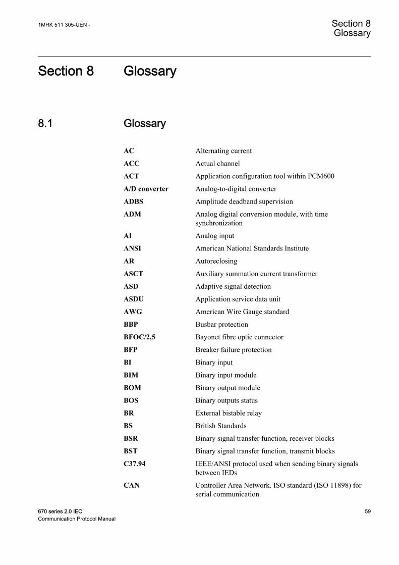
Section 8 Glossary
8.1 Glossary
AC Alternating current
ACC Actual channel
ACT Application configuration tool within PCM600
A/D converter Analog-to-digital converter
ADBS Amplitude deadband supervision
ADM Analog digital conversion module, with timesynchronization
AI Analog input
ANSI American National Standards Institute
AR Autoreclosing
ASCT Auxiliary summation current transformer
ASD Adaptive signal detection
ASDU Application service data unit
AWG American Wire Gauge standard
BBP Busbar protection
BFOC/2,5 Bayonet fibre optic connector
BFP Breaker failure protection
BI Binary input
BIM Binary input module
BOM Binary output module
BOS Binary outputs status
BR External bistable relay
BS British Standards
BSR Binary signal transfer function, receiver blocks
BST Binary signal transfer function, transmit blocks
C37.94 IEEE/ANSI protocol used when sending binary signalsbetween IEDs
CAN Controller Area Network. ISO standard (ISO 11898) forserial communication
1MRK 511 305-UEN - Section 8Glossary
670 series 2.0 IEC 59Communication Protocol Manual

CB Circuit breaker
CBM Combined backplane module
CCITT Consultative Committee for International Telegraph andTelephony. A United Nations-sponsored standards bodywithin the International Telecommunications Union.
CCM CAN carrier module
CCVT Capacitive Coupled Voltage Transformer
Class C Protection Current Transformer class as per IEEE/ ANSI
CMPPS Combined megapulses per second
CMT Communication Management tool in PCM600
CO cycle Close-open cycle
Codirectional Way of transmitting G.703 over a balanced line. Involvestwo twisted pairs making it possible to transmitinformation in both directions
COM Command
COMTRADE Standard Common Format for Transient Data Exchangeformat for Disturbance recorder according to IEEE/ANSIC37.111, 1999 / IEC60255-24
Contra-directional Way of transmitting G.703 over a balanced line. Involvesfour twisted pairs, two of which are used for transmittingdata in both directions and two for transmitting clock signals
COT Cause of transmission
CPU Central processing unit
CR Carrier receive
CRC Cyclic redundancy check
CROB Control relay output block
CS Carrier send
CT Current transformer
CU Communication unit
CVT or CCVT Capacitive voltage transformer
DAR Delayed autoreclosing
DARPA Defense Advanced Research Projects Agency (The USdeveloper of the TCP/IP protocol etc.)
DBDL Dead bus dead line
DBLL Dead bus live line
DC Direct current
DFC Data flow control
Section 8 1MRK 511 305-UEN -Glossary
60 670 series 2.0 IECCommunication Protocol Manual

DFT Discrete Fourier transform
DHCP Dynamic Host Configuration Protocol
DIP-switch Small switch mounted on a printed circuit board
DI Digital input
DLLB Dead line live bus
DNP Distributed Network Protocol as per IEEE Std 1815-2012
DR Disturbance recorder
DRAM Dynamic random access memory
DRH Disturbance report handler
DSP Digital signal processor
DTT Direct transfer trip scheme
EHV network Extra high voltage network
EIA Electronic Industries Association
EMC Electromagnetic compatibility
EMF Electromotive force
EMI Electromagnetic interference
EnFP End fault protection
EPA Enhanced performance architecture
ESD Electrostatic discharge
F-SMA Type of optical fibre connector
FAN Fault number
FCB Flow control bit; Frame count bit
FOX 20 Modular 20 channel telecommunication system for speech,data and protection signals
FOX 512/515 Access multiplexer
FOX 6Plus Compact time-division multiplexer for the transmission ofup to seven duplex channels of digital data over optical fibers
FUN Function type
G.703 Electrical and functional description for digital lines usedby local telephone companies. Can be transported overbalanced and unbalanced lines
GCM Communication interface module with carrier of GPSreceiver module
GDE Graphical display editor within PCM600
GI General interrogation command
GIS Gas-insulated switchgear
1MRK 511 305-UEN - Section 8Glossary
670 series 2.0 IEC 61Communication Protocol Manual

GOOSE Generic object-oriented substation event
GPS Global positioning system
GSAL Generic security application
GTM GPS Time Module
HDLC protocol High-level data link control, protocol based on the HDLCstandard
HFBR connectortype
Plastic fiber connector
HMI Human-machine interface
HSAR High speed autoreclosing
HV High-voltage
HVDC High-voltage direct current
IDBS Integrating deadband supervision
IEC International Electrical Committee
IEC 60044-6 IEC Standard, Instrument transformers – Part 6:Requirements for protective current transformers fortransient performance
IEC 60870-5-103 Communication standard for protection equipment. Aserial master/slave protocol for point-to-pointcommunication
IEC 61850 Substation automation communication standard
IEC 61850–8–1 Communication protocol standard
IEEE Institute of Electrical and Electronics Engineers
IEEE 802.12 A network technology standard that provides 100 Mbits/son twisted-pair or optical fiber cable
IEEE P1386.1 PCI Mezzanine Card (PMC) standard for local busmodules. References the CMC (IEEE P1386, also knownas Common Mezzanine Card) standard for the mechanicsand the PCI specifications from the PCI SIG (SpecialInterest Group) for the electrical EMF (Electromotive force).
IEEE 1686 Standard for Substation Intelligent Electronic Devices(IEDs) Cyber Security Capabilities
IED Intelligent electronic device
I-GIS Intelligent gas-insulated switchgear
IOM Binary input/output module
Instance When several occurrences of the same function areavailable in the IED, they are referred to as instances ofthat function. One instance of a function is identical toanother of the same kind but has a different number in the
Section 8 1MRK 511 305-UEN -Glossary
62 670 series 2.0 IECCommunication Protocol Manual

IED user interfaces. The word "instance" is sometimesdefined as an item of information that is representative of atype. In the same way an instance of a function in the IEDis representative of a type of function.
IP 1. Internet protocol. The network layer for the TCP/IPprotocol suite widely used on Ethernet networks. IP is aconnectionless, best-effort packet-switching protocol. Itprovides packet routing, fragmentation and reassemblythrough the data link layer.2. Ingression protection, according to IEC 60529
IP 20 Ingression protection, according to IEC 60529, level 20
IP 40 Ingression protection, according to IEC 60529, level 40
IP 54 Ingression protection, according to IEC 60529, level 54
IRF Internal failure signal
IRIG-B: InterRange Instrumentation Group Time code format B,standard 200
ITU International Telecommunications Union
LAN Local area network
LIB 520 High-voltage software module
LCD Liquid crystal display
LDCM Line differential communication module
LDD Local detection device
LED Light-emitting diode
LNT LON network tool
LON Local operating network
MCB Miniature circuit breaker
MCM Mezzanine carrier module
MIM Milli-ampere module
MPM Main processing module
MVAL Value of measurement
MVB Multifunction vehicle bus. Standardized serial busoriginally developed for use in trains.
NCC National Control Centre
NOF Number of grid faults
NUM Numerical module
OCO cycle Open-close-open cycle
OCP Overcurrent protection
1MRK 511 305-UEN - Section 8Glossary
670 series 2.0 IEC 63Communication Protocol Manual

OEM Optical Ethernet module
OLTC On-load tap changer
OTEV Disturbance data recording initiated by other event than start/pick-up
OV Overvoltage
Overreach A term used to describe how the relay behaves during afault condition. For example, a distance relay isoverreaching when the impedance presented to it is smallerthan the apparent impedance to the fault applied to thebalance point, that is, the set reach. The relay “sees” thefault but perhaps it should not have seen it.
PCI Peripheral component interconnect, a local data bus
PCM Pulse code modulation
PCM600 Protection and control IED manager
PC-MIP Mezzanine card standard
PMC PCI Mezzanine card
POR Permissive overreach
POTT Permissive overreach transfer trip
Process bus Bus or LAN used at the process level, that is, in nearproximity to the measured and/or controlled components
PSM Power supply module
PST Parameter setting tool within PCM600
PT ratio Potential transformer or voltage transformer ratio
PUTT Permissive underreach transfer trip
RASC Synchrocheck relay, COMBIFLEX
RCA Relay characteristic angle
RISC Reduced instruction set computer
RMS value Root mean square value
RS422 A balanced serial interface for the transmission of digitaldata in point-to-point connections
RS485 Serial link according to EIA standard RS485
RTC Real-time clock
RTU Remote terminal unit
SA Substation Automation
SBO Select-before-operate
SC Switch or push button to close
SCL Short circuit location
Section 8 1MRK 511 305-UEN -Glossary
64 670 series 2.0 IECCommunication Protocol Manual

SCS Station control system
SCADA Supervision, control and data acquisition
SCT System configuration tool according to standard IEC 61850
SDU Service data unit
SLM Serial communication module.
SMA connector Subminiature version A, A threaded connector withconstant impedance.
SMT Signal matrix tool within PCM600
SMS Station monitoring system
SNTP Simple network time protocol – is used to synchronizecomputer clocks on local area networks. This reduces therequirement to have accurate hardware clocks in everyembedded system in a network. Each embedded node caninstead synchronize with a remote clock, providing therequired accuracy.
SOF Status of fault
SPA Strömberg Protection Acquisition (SPA), a serial master/slave protocol for point-to-point communication
SRY Switch for CB ready condition
ST Switch or push button to trip
Starpoint Neutral point of transformer or generator
SVC Static VAr compensation
TC Trip coil
TCS Trip circuit supervision
TCP Transmission control protocol. The most commontransport layer protocol used on Ethernet and the Internet.
TCP/IP Transmission control protocol over Internet Protocol. Thede facto standard Ethernet protocols incorporated into4.2BSD Unix. TCP/IP was developed by DARPA forInternet working and encompasses both network layer andtransport layer protocols. While TCP and IP specify twoprotocols at specific protocol layers, TCP/IP is often usedto refer to the entire US Department of Defense protocolsuite based upon these, including Telnet, FTP, UDP andRDP.
TEF Time delayed earth-fault protection function
TM Transmit (disturbance data)
TNC connector Threaded Neill-Concelman, a threaded constant impedanceversion of a BNC connector
1MRK 511 305-UEN - Section 8Glossary
670 series 2.0 IEC 65Communication Protocol Manual

TP Trip (recorded fault)
TPZ, TPY, TPX,TPS
Current transformer class according to IEC
TRM Transformer Module. This module transforms currents andvoltages taken from the process into levels suitable forfurther signal processing.
TYP Type identification
UMT User management tool
Underreach A term used to describe how the relay behaves during afault condition. For example, a distance relay isunderreaching when the impedance presented to it isgreater than the apparent impedance to the fault applied tothe balance point, that is, the set reach. The relay does not“see” the fault but perhaps it should have seen it. See alsoOverreach.
UTC Coordinated Universal Time. A coordinated time scale,maintained by the Bureau International des Poids etMesures (BIPM), which forms the basis of a coordinateddissemination of standard frequencies and time signals.UTC is derived from International Atomic Time (TAI) bythe addition of a whole number of "leap seconds" tosynchronize it with Universal Time 1 (UT1), thus allowingfor the eccentricity of the Earth's orbit, the rotational axistilt (23.5 degrees), but still showing the Earth's irregularrotation, on which UT1 is based. The CoordinatedUniversal Time is expressed using a 24-hour clock, anduses the Gregorian calendar. It is used for aeroplane andship navigation, where it is also sometimes known by themilitary name, "Zulu time." "Zulu" in the phoneticalphabet stands for "Z", which stands for longitude zero.
UV Undervoltage
WEI Weak end infeed logic
VT Voltage transformer
X.21 A digital signalling interface primarily used for telecomequipment
3IO Three times zero-sequence current.Often referred to as theresidual or the earth-fault current
3UO Three times the zero sequence voltage. Often referred to asthe residual voltage or the neutral point voltage
Section 8 1MRK 511 305-UEN -Glossary
66 670 series 2.0 IECCommunication Protocol Manual

67

Contact us
ABB ABSubstation Automation ProductsSE-721 59 Västerås, SwedenPhone +46 (0) 21 32 50 00Fax +46 (0) 21 14 69 18
www.abb.com/substationautomation
1MR
K 5
11 3
05-U
EN
-©
Cop
yrig
ht 2
014
AB
B. A
ll rig
hts
rese
rved
.
Top Related