


Languages
Pages
Legal

TELECOM / DATACOM SYSTEMS
Lightem LSFP+158CG-XX-DWDM10Gb/s DWDM 80KM SFP+ Optical Transceivers
Features
Applications
Lightem LSFP+158CG-XX-DWDM SFP+ transceivers are designed for 10G Ethernet 10G BASE-ZR and 8.5/10G Fiber Channels. It supports data-rate from 9.953Gb/s to 11.1Gb/ s, with built in.Digital diagnostics (DDMI).
The transceiver designs are optimized for high performance and cost effective to supply customers the best solutions for datacom and telecom applications. The transmitter incorporates a temperature stabilized cooled EML laser and a APD photodiode integrated with TIA. DDMI is available for real time monitoring for parameter such as temperature, bias current, transmitted and received optical power etc.
100GHz channel spacing DWDM systemsSupport ≤4.25Gbps or 9.95Gbps to 10.3GbpsTemperature stabilized cooled EML transmitter and APD receiver Compliant with SFF-8413 and IEE802.3aeUp to 80km transmission distanceOperating Case Temperature - Commercial: -5ºC to 70ºC Industrial: -40°C to +85°CLow Power Dissipation 1.5W MaximumSingle 3.3V power supplyDDMI for module temperature, supply voltages, laser bias current, transmit optical power, receive optical power RoHS compliant
DWDM Networks10G BASE-ZR80KM 10G Fiber Channel
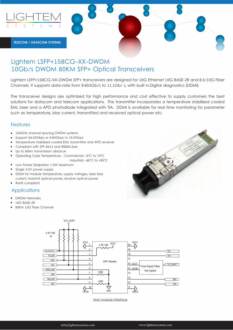
Host module interface
TELECOM / DATACOM SYSTEMS
Absolute Maximum Ratings
ParameterSupply Voltage Storage TemperatureRelative Humidity
SymbolVccTstRh
Min-0.5-400
Max3.88585
UnitVºC%
Operating Conditions
ParameterSupply VoltageSupply currentOperating Case temperature:Commercial gradeIndustrial gradeModule Power Dissipation
SymbolVccIcc
TcaseTcasePm
Min3.13
-5-40-
Typical3.3420
--1.4
Max3.47610
70852
UnitVmA
ºCºCW
Notes:[1] Supply current is shared between VCCTX and VCCRX.[2] In-rush is defined as current level above steady state current requirements.
Transmitter Specifications – Optical
ParameterCenter Wavelength (SOL)△Center Wavelength (EOL)▲Optical OMA PowerSide Mode Suppression RatioOptical Transmit Power (disabled)Extinction RatioRIN21OMA [1]Optical Return Loss Tolerance
Symbolc c PomSMSRPTX_DISABLEER
Minc -25c-130-9
Typicalcc
--
Maxc +25c+100
--30--12821
UnitpmpmdBmdBdBmdBdB/HzdB
Notes:[1] RIN measurement is made with a return loss at 21 dB.△Laser- Start of Life▲Laser End of life
Transmitter Specifications – Electrical
ParameterData RateInput differential impedanceDifferential data InputTransmit Disable VoltageTransmit Enable VoltageTransmit Disable Assert Time
SymbolMraRimVtxDIFFVDVenVn
Min--1202.00-
Typical10.3100----
Max11.3-850Vcc3+0.3+0.8100
UnitGbpsΩmVVVus
TELECOM / DATACOM SYSTEMS
Receiver Specifications – Optical
ParameterInput Operating WavelengthReceiver sensitivity in OMAMaximum Input PowerLoss of Signal AssertedLOS De-AssertedLOS Hysteresis
Symbolλ
RX-overload
Min1260---34-0.5
Typical------
Max1620-24-8--24-
UnitnmdBmdBmdBmdBmdB
Notes: [1] Measured with conformance test signal for BER = 10–12. The stressed sensitivity values in the table are for system level BER measurements which include the effects of CDR circuits. It is recommended that at least 0.4 dB additional margin be allocated if component level measurements are made without the effects of CDR circuits.
Receiver Specifications – Electrical
ParameterData RateDifferential Output SwingRise/Fall TimeLoss of Signal –AssertedLoss of Signal –Negated
SymbolMraVout P-PTr / TfVOHVOL
Min-3502420
Typical10.3----
Max11.3850-Vcc3+0.3+0.4
UnitGbpsmVpsVV
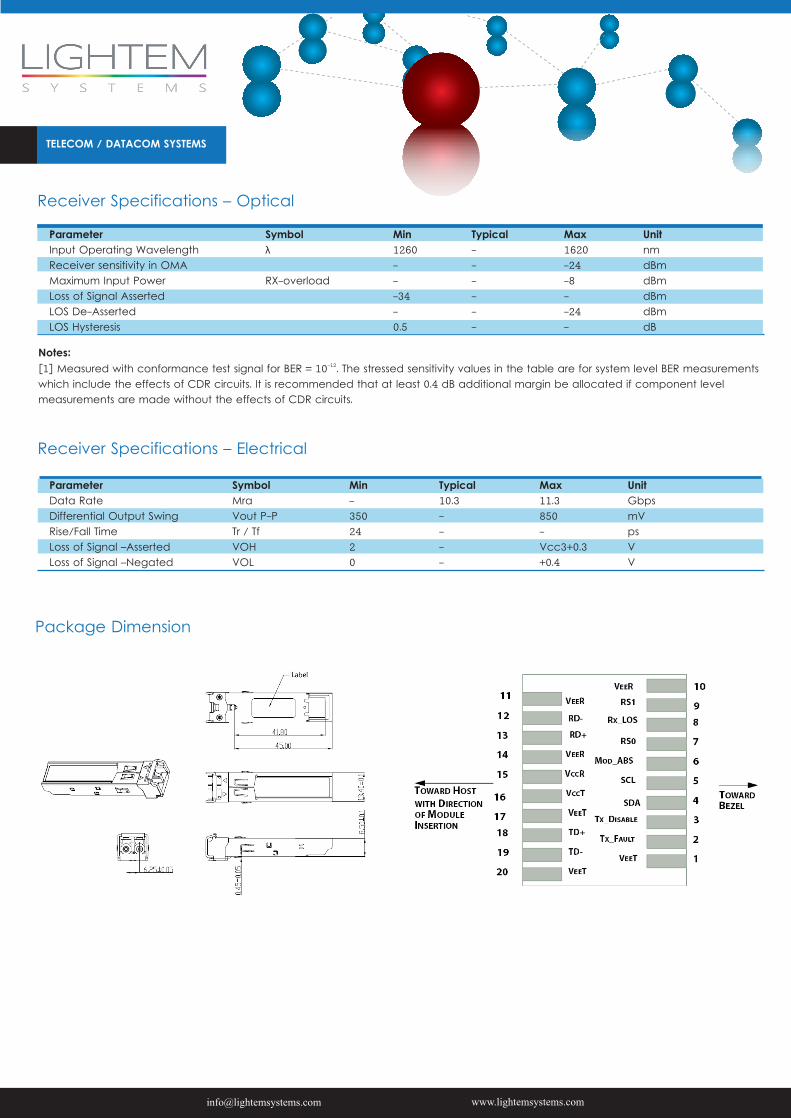
Package Dimension
TELECOM / DATACOM SYSTEMS
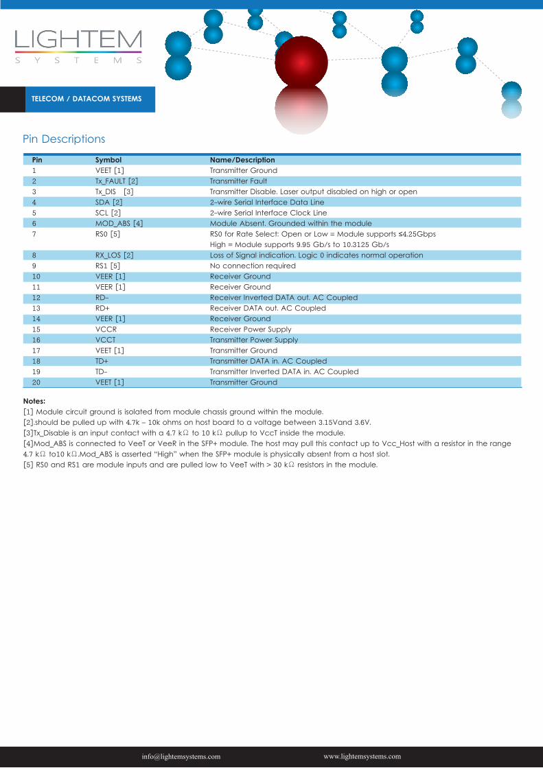
Pin Descriptions
Pin1234567
891011121314151617181920
SymbolVEET [1]Tx_FAULT [2]Tx_DIS [3]SDA [2]SCL [2]MOD_ABS [4]RS0 [5]
RX_LOS [2]RS1 [5]VEER [1]VEER [1]RD-RD+VEER [1]VCCRVCCTVEET [1]TD+TD-VEET [1]
Name/DescriptionTransmitter GroundTransmitter FaultTransmitter Disable. Laser output disabled on high or open2-wire Serial Interface Data Line2-wire Serial Interface Clock LineModule Absent. Grounded within the moduleRS0 for Rate Select: Open or Low = Module supports ≤4.25Gbps High = Module supports 9.95 Gb/s to 10.3125 Gb/sLoss of Signal indication. Logic 0 indicates normal operationNo connection requiredReceiver GroundReceiver GroundReceiver Inverted DATA out. AC CoupledReceiver DATA out. AC CoupledReceiver GroundReceiver Power SupplyTransmitter Power SupplyTransmitter GroundTransmitter DATA in. AC CoupledTransmitter Inverted DATA in. AC CoupledTransmitter Ground
Notes: [1] Module circuit ground is isolated from module chassis ground within the module.[2].should be pulled up with 4.7k – 10k ohms on host board to a voltage between 3.15Vand 3.6V.[3]Tx_Disable is an input contact with a 4.7 kΩ to 10 kΩ pullup to VccT inside the module.[4]Mod_ABS is connected to VeeT or VeeR in the SFP+ module. The host may pull this contact up to Vcc_Host with a resistor in the range 4.7 kΩ to10 kΩ.Mod_ABS is asserted “High” when the SFP+ module is physically absent from a host slot.[5] RS0 and RS1 are module inputs and are pulled low to VeeT with > 30 kΩ resistors in the module.
TELECOM / DATACOM SYSTEMS
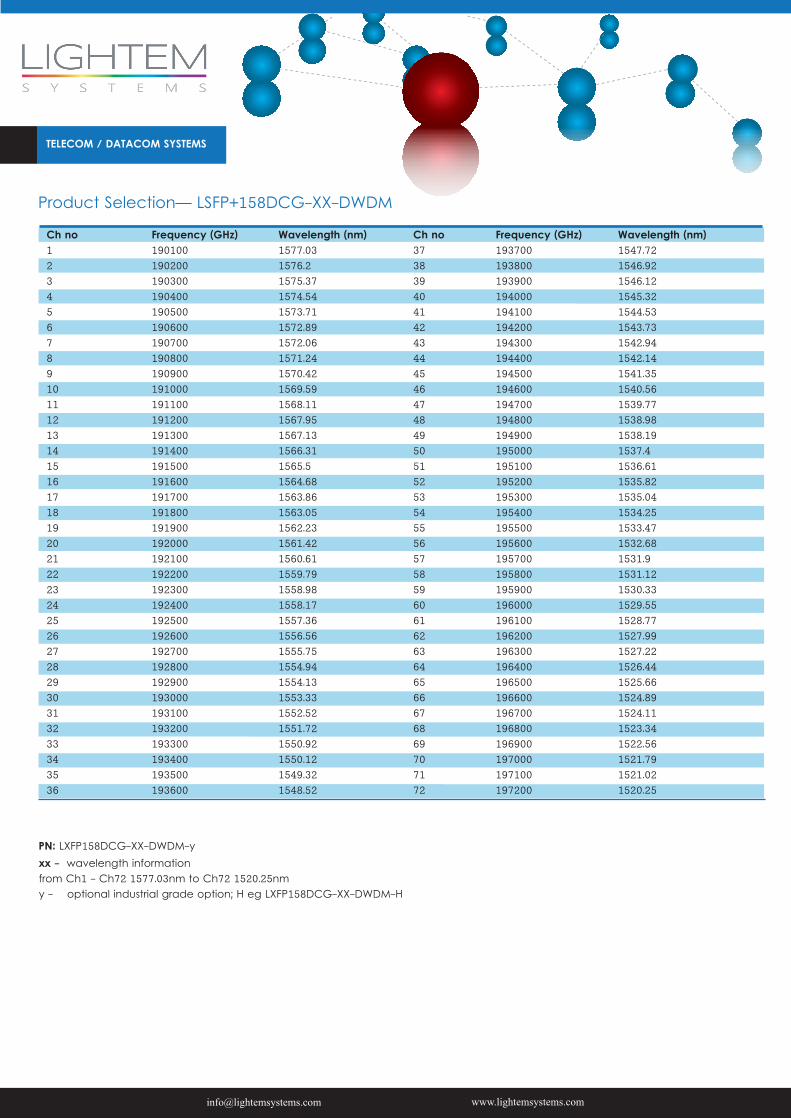
Product Selection— LSFP+158DCG-XX-DWDM
Ch no 12 34 56 78 910 1112 1314 1516 1718 1920 2122 2324 2526 2728 2930 3132 3334 3536
Frequency (GHz)190100190200 190300190400 190500190600 190700190800 190900191000 191100191200 191300191400 191500191600 191700191800 191900192000 192100192200 192300192400 192500192600 192700192800 192900193000 193100193200 193300193400 193500193600
Wavelength (nm)1577.03 1576.21575.37 1574.541573.71 1572.891572.06 1571.241570.42 1569.591568.11 1567.951567.13 1566.311565.5 1564.681563.86 1563.051562.23 1561.421560.61 1559.791558.98 1558.171557.36 1556.561555.75 1554.941554.13 1553.331552.52 1551.721550.92 1550.121549.32 1548.52
Ch no 373839404142434445464748495051525354555657585960616263646566676869707172
Frequency (GHz)193700 193800 193900 194000 194100 194200 194300 194400 194500 194600 194700 194800 194900 195000 195100 195200 195300 195400 195500 195600 195700 195800 195900 196000 196100 196200 196300 196400 196500 196600 196700 196800 196900 197000 197100 197200
Wavelength (nm)1547.721546.92 1546.121545.32 1544.531543.73 1542.941542.14 1541.351540.56 1539.771538.98 1538.191537.4 1536.611535.82 1535.041534.25 1533.471532.68 1531.91531.12 1530.331529.55 1528.771527.99 1527.221526.44 1525.661524.89 1524.111523.34 1522.561521.79 1521.021520.25
PN: LXFP158DCG-XX-DWDM-yxx - wavelength informationfrom Ch1 - Ch72 1577.03nm to Ch72 1520.25nmy - optional industrial grade option; H eg LXFP158DCG-XX-DWDM-H
Top Related