


Languages
Pages
Legal

Level Measurement with Radar and UltrasonicNorCal Tech 2005 Technical Conference
Level Measurement with Radar and Ultrasonic
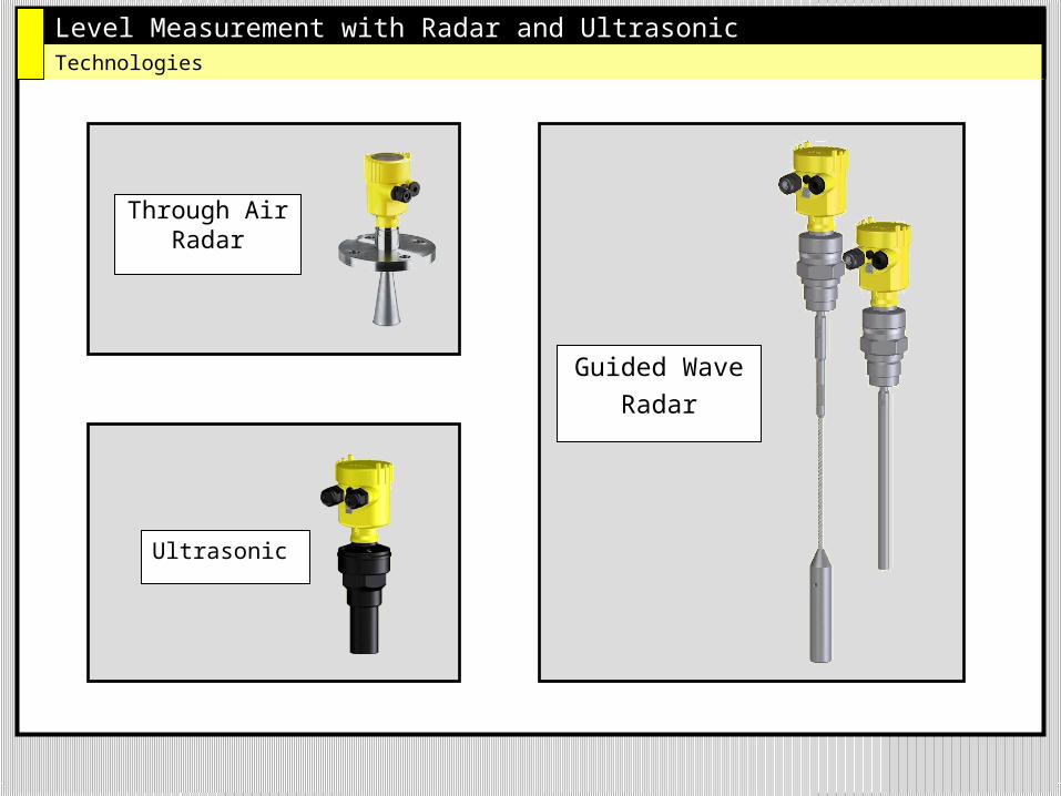
Level Measurement with Radar and UltrasonicTechnologies
Through AirRadar
Guided Wave
Radar
Ultrasonic
Level Measurement with Radar and UltrasonicHow it works
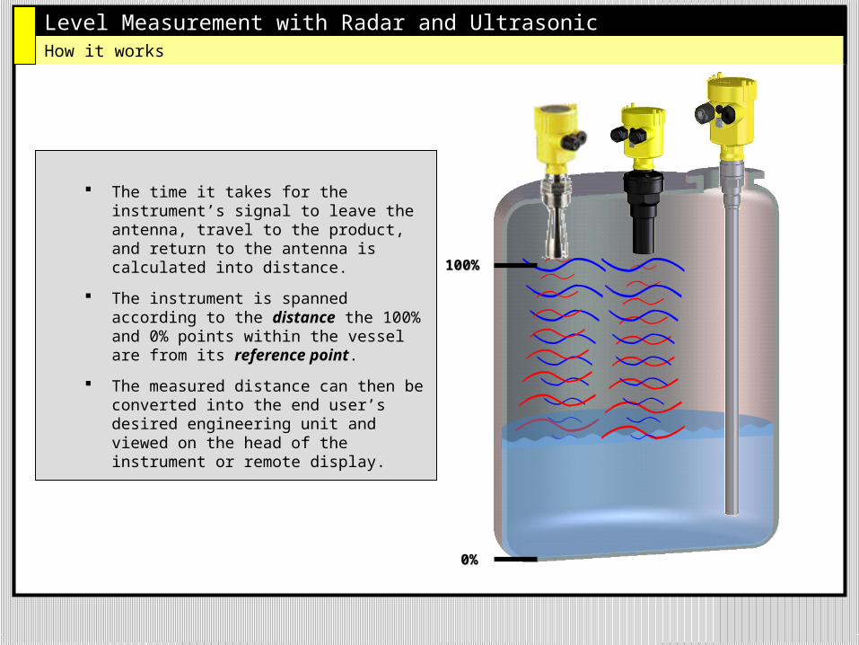
The time it takes for the instrument’s signal to leave the antenna, travel to the product, and return to the antenna is calculated into distance.
The instrument is spanned according to the distance the 100% and 0% points within the vessel are from its reference point.
The measured distance can then be converted into the end user’s desired engineering unit and viewed on the head of the instrument or remote display.
100%100%
0%0%
Level Measurement with Radar and Ultrasonic
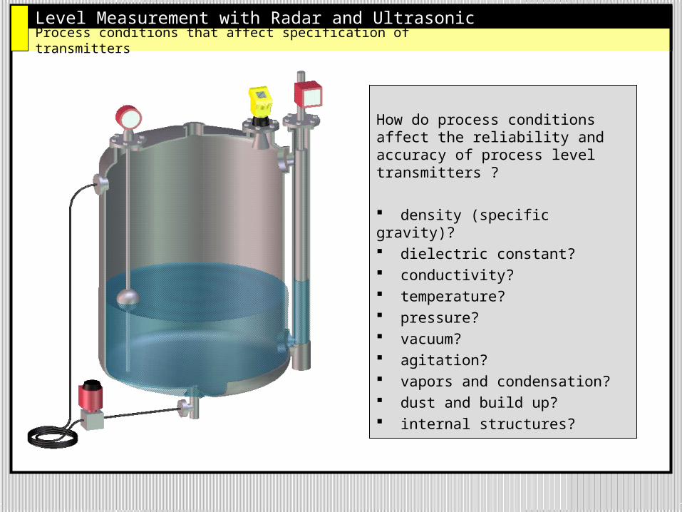
How do process conditions affect the reliability and accuracy of process level transmitters ?
density (specific gravity)? dielectric constant? conductivity? temperature? pressure? vacuum? agitation? vapors and condensation? dust and build up? internal structures?
Process conditions that affect specification of transmitters
Level Measurement with Radar and Ultrasonic
Through Air Radar
Level Measurement with Radar and UltrasonicRadar Technology – How it works
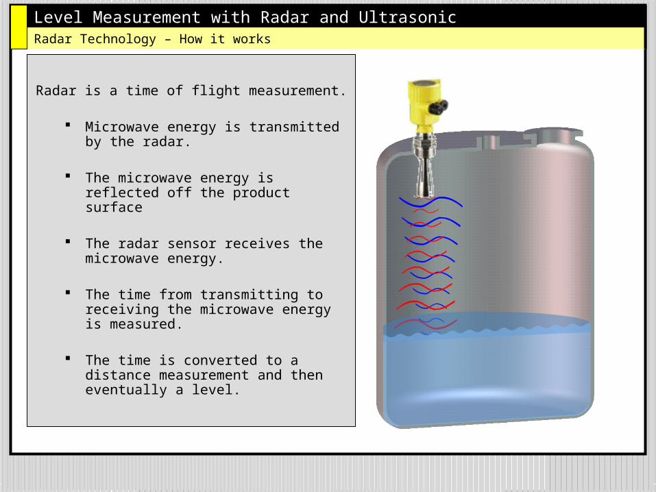
Radar is a time of flight measurement.
Microwave energy is transmitted by the radar.
The microwave energy is reflected off the product surface
The radar sensor receives the microwave energy.
The time from transmitting to receiving the microwave energy is measured.
The time is converted to a distance measurement and then eventually a level.
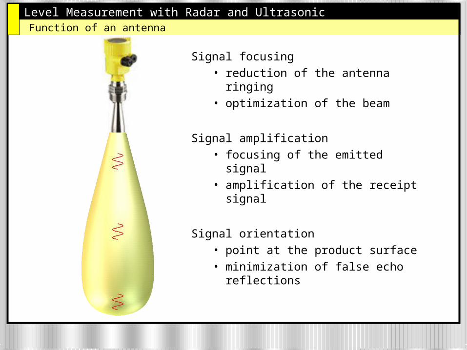
Level Measurement with Radar and UltrasonicFunction of an antenna
Signal focusing• reduction of the antenna
ringing• optimization of the beam
Signal amplification• focusing of the emitted signal• amplification of the receipt
signal
Signal orientation• point at the product surface • minimization of false echo
reflections
Level Measurement with Radar and Ultrasonic
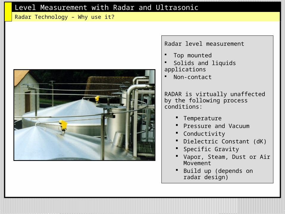
Radar level measurement
Top mounted Solids and liquids applications Non-contact
RADAR is virtually unaffected by the following process conditions:
Temperature Pressure and Vacuum Conductivity Dielectric Constant (dK) Specific Gravity Vapor, Steam, Dust or Air
Movement Build up (depends on
radar design)
Radar Technology – Why use it?
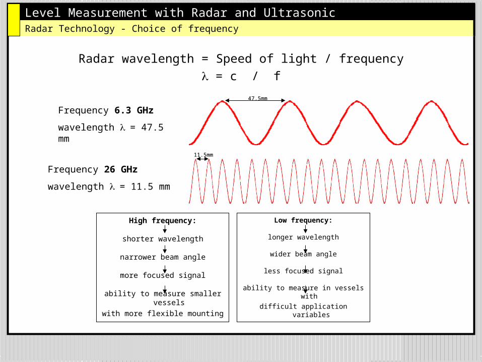
Level Measurement with Radar and UltrasonicRadar Technology - Choice of frequency
Radar wavelength = Speed of light / frequency = c / f
Frequency 6.3 GHz
wavelength = 47.5 mm
Frequency 26 GHz
wavelength = 11.5 mm
High frequency:
shorter wavelength
narrower beam angle
more focused signal
ability to measure smaller vessels
with more flexible mounting
47.5mm47.5mm
11.5mm11.5mm
Low frequency:
longer wavelength
wider beam angle
less focused signal
ability to measure in vessels with
difficult application variables
Level Measurement with Radar and Ultrasonic
5 GHz 10 GHzFrequency
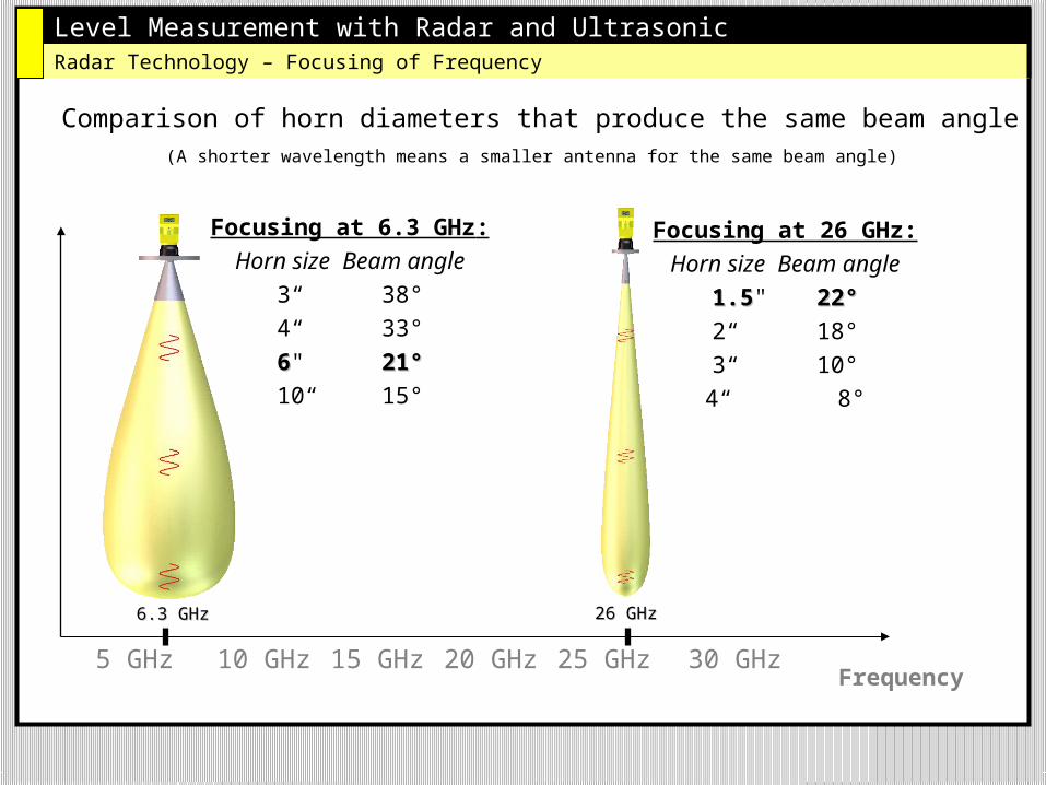
Comparison of horn diameters that produce the same beam angle
20 GHz15 GHz 25 GHz
Focusing at 6.3 GHz:
Horn size Beam angle
3“ 38°
4“ 33°
66" 21°21°
10“ 15°
Focusing at 26 GHz:
Horn size Beam angle
1.51.5" 22°22°
2“ 18°
3“ 10°
4“ 8°
Radar Technology – Focusing of Frequency
30 GHz
6.3 GHz6.3 GHz 26 GHz26 GHz
(A shorter wavelength means a smaller antenna for the same beam angle)
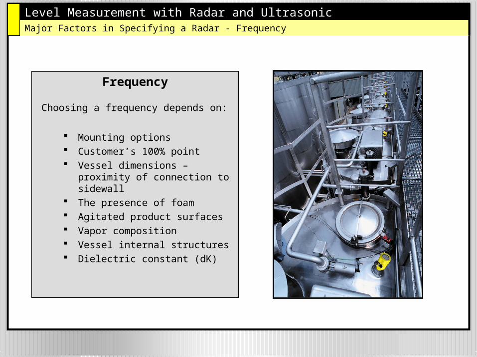
Level Measurement with Radar and UltrasonicMajor Factors in Specifying a Radar - Frequency
Frequency
Choosing a frequency depends on:
Mounting options Customer’s 100% point Vessel dimensions –
proximity of connection to sidewall
The presence of foam Agitated product surfaces Vapor composition Vessel internal structures Dielectric constant (dK)
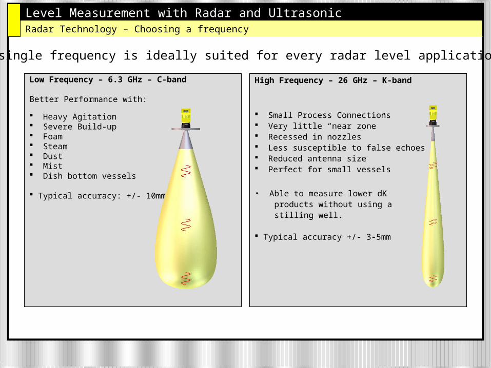
Level Measurement with Radar and UltrasonicRadar Technology – Choosing a frequency
Low Frequency – 6.3 GHz – C-band
Better Performance with:
Heavy Agitation Severe Build-up Foam Steam Dust Mist Dish bottom vessels
Typical accuracy: +/- 10mm
High Frequency – 26 GHz – K-band
Small Process Connections Very little “near zone” Recessed in nozzles Less susceptible to false echoes Reduced antenna size Perfect for small vessels
• Able to measure lower dK products without using a stilling well.
Typical accuracy +/- 3-5mm
No single frequency is ideally suited for every radar level application.
Level Measurement with Radar and Ultrasonic
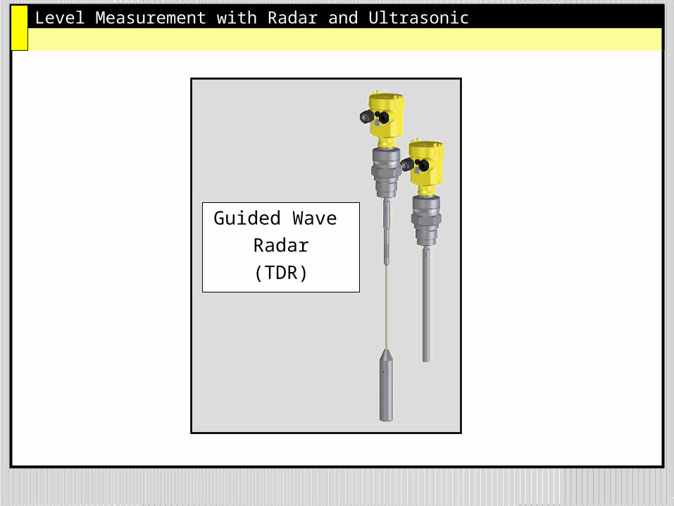
Guided Wave
Radar
(TDR)
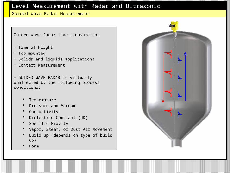
Level Measurement with Radar and UltrasonicGuided Wave Radar Measurement
Guided Wave Radar level measurement
• Time of Flight • Top mounted• Solids and liquids applications• Contact Measurement
• GUIDED WAVE RADAR is virtually unaffected by the following process conditions:
Temperature Pressure and Vacuum Conductivity Dielectric Constant (dK) Specific Gravity Vapor, Steam, or Dust Air Movement Build up (depends on type of build up) Foam
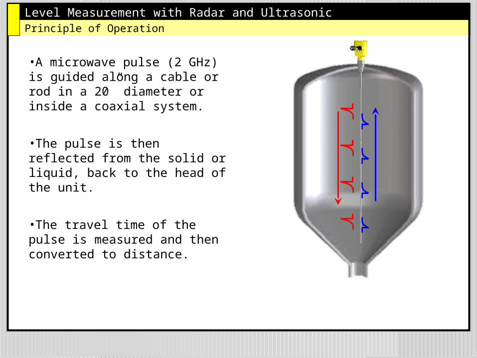
Level Measurement with Radar and UltrasonicPrinciple of Operation
•A microwave pulse (2 GHz) is guided along a cable or rod in a 20” diameter or inside a coaxial system.
•The pulse is then reflected from the solid or liquid, back to the head of the unit.
•The travel time of the pulse is measured and then converted to distance.
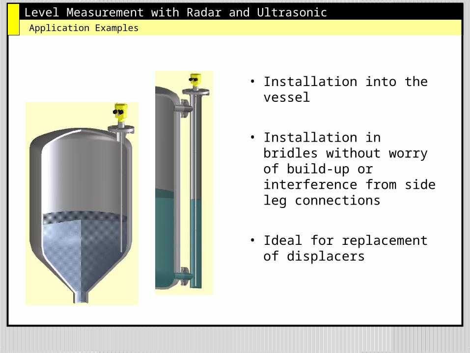
Level Measurement with Radar and UltrasonicApplication Examples
• Installation into the vessel
• Installation in bridles without worry of build-up or interference from side leg connections
• Ideal for replacement of displacers
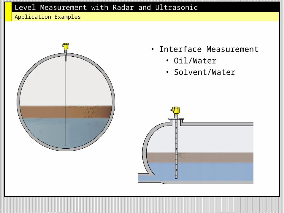
Level Measurement with Radar and UltrasonicApplication Examples
• Interface Measurement• Oil/Water• Solvent/Water
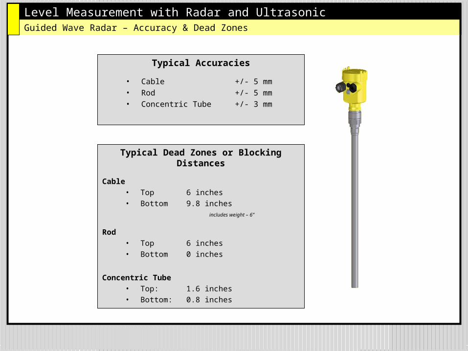
Level Measurement with Radar and UltrasonicGuided Wave Radar – Accuracy & Dead Zones
Typical Accuracies
• Cable +/- 5 mm• Rod +/- 5 mm• Concentric Tube +/- 3 mm
Typical Dead Zones or Blocking Distances
Cable• Top 6 inches• Bottom 9.8 inches
includes weight – 6”
Rod• Top 6 inches• Bottom 0 inches
Concentric Tube• Top: 1.6 inches• Bottom: 0.8 inches
Level Measurement with Radar and Ultrasonic
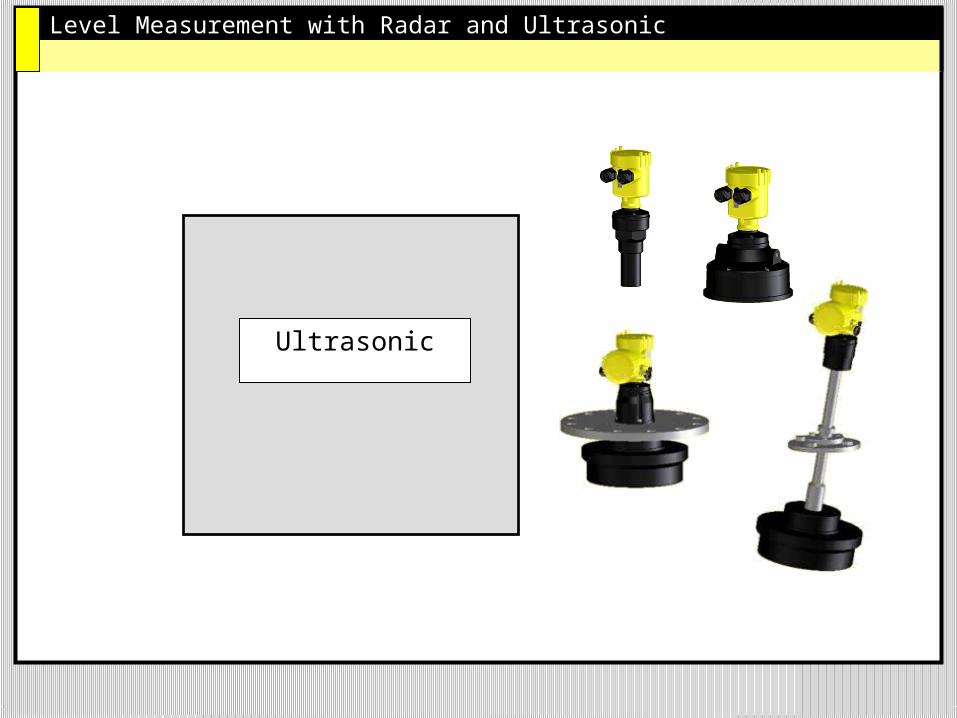
Ultrasonic
Level Measurement with Radar and UltrasonicUltrasonic Level Measurement
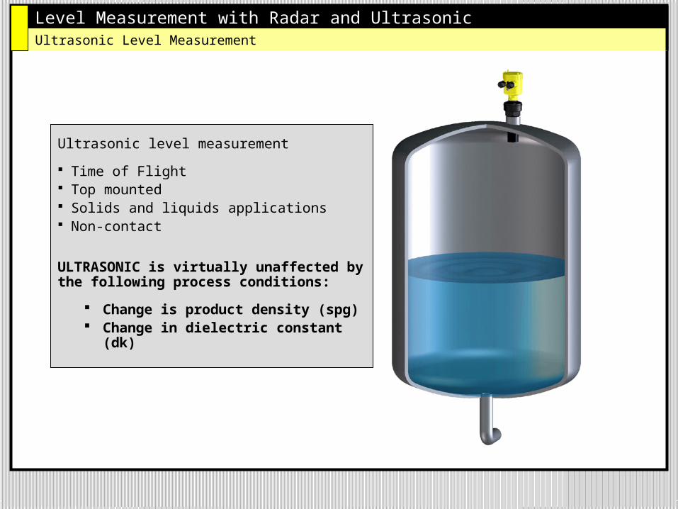
Ultrasonic level measurement
Time of Flight Top mounted Solids and liquids applications Non-contact
ULTRASONIC is virtually unaffected by the following process conditions:
Change is product density (spg) Change in dielectric constant
(dk)
Level Measurement with Radar and UltrasonicUltrasonic Level Measurement – How it works
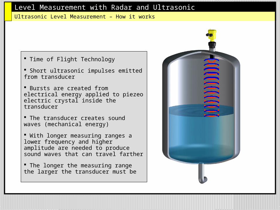
Time of Flight Technology
Short ultrasonic impulses emitted from transducer
Bursts are created from electrical energy applied to piezeo electric crystal inside the transducer
The transducer creates sound waves (mechanical energy)
With longer measuring ranges a lower frequency and higher amplitude are needed to produce sound waves that can travel farther
The longer the measuring range the larger the transducer must be
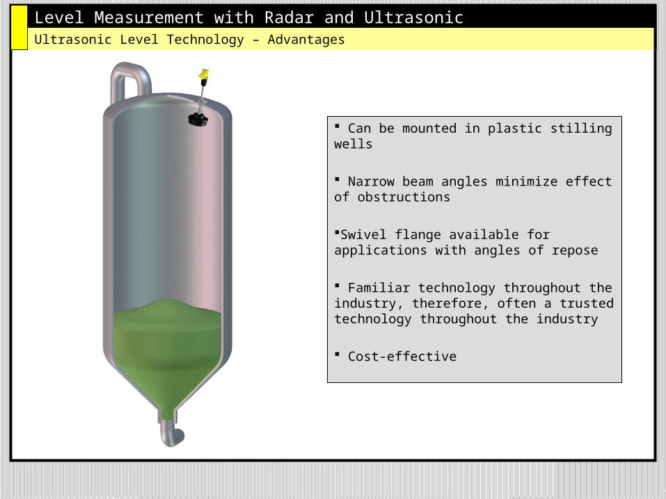
Level Measurement with Radar and UltrasonicUltrasonic Level Technology – Advantages
Can be mounted in plastic stilling wells
Narrow beam angles minimize effect of obstructions
Swivel flange available for applications with angles of repose
Familiar technology throughout the industry, therefore, often a trusted technology throughout the industry
Cost-effective
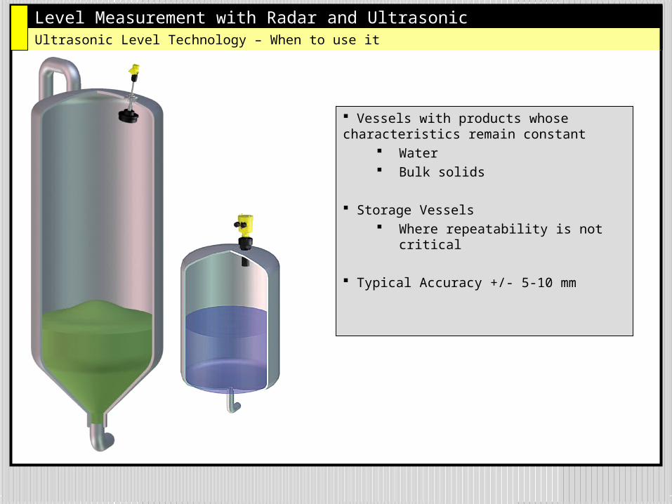
Level Measurement with Radar and UltrasonicUltrasonic Level Technology – When to use it
Vessels with products whose characteristics remain constant
Water Bulk solids
Storage Vessels Where repeatability is not critical
Typical Accuracy +/- 5-10 mm
Level Measurement with Radar and UltrasonicQuestions?
Questions?
Top Related