


![TIM Specification for Gm Interface between an User ......[DOC12] RFC 3841 - Caller Preferences for the Session Initiation Protocol (SIP) [DOC13] RFC 3325 - SIP Asserted Identity [DOC14]](https://static.fdocuments.in/doc/165x107/60cadc0837f555347812d3e3/tim-specification-for-gm-interface-between-an-user-doc12-rfc-3841-caller.jpg)


Languages
Pages
Legal

August 8, 2017
Lemonbeat SiP M001System in Package Chip and Software Stack
Data Sheet
Version 3.0
1. Lemonbeat SiP Chip M001 - Hardware Specification 3
2. Chip design 5
3. TÜV Süd - Test report - TÜV test result page and main test results 6
4. Lemonbeat SiP M001 pin configuration and allocation 8
5. Programming and debugging 10
6. Soldering profile 11
7. Lemonbeat Software Stack - Features 12
8. Lemonbeat Services 14
8.1 Services for configuring the logical engine 14
8.2 Additional services 16
Table of contents
Hardware
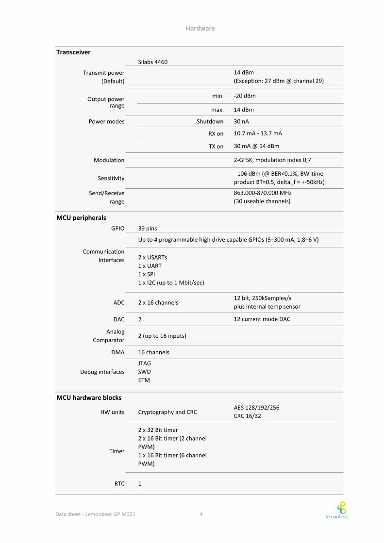
Manufacturer Silicon Labs
Package LGA105
Type Transceiver + MCU
MCU Core ARM Cortex-M3 @ 80MHz
Memory Flash 256 kb
RAM 32 kb (4kb retained in power down)
Transceiver Silicon Labs SI 4460
Transmit data rate 100 kbit/s
Operating Temperature -40 °C to 85 °C
Size 11 x 11 x 1 mm
+1.8 V to +3.6 V
WoRPeak ≈ 39.00 mA ± 2mA
WoRSleep ≈ 10.5 µA ± 2.0 µA
WoRPeriod_Average ≈ 148.0 µA ± 2.0 µA
Period duration WoRPeriod_WoR ≈ 330 ms ± 2.0 ms
WoRPeak_WoR ≈ 1.5 ms ± 0.2 ms
Frequency range (send/receive)
RF output - impedance (pin 38) 50 Ω
1. Lemonbeat SiP M001
The Lemonbeat SiP (System in Package) module is a complete hardware MCU-RF solution that enables the
handling of the Lemonbeat Software Stack and specific application code.
The Lemonbeat SiP module makes it easy to implement advanced functionality with an optimized hardware
and minimal programming effort because all critical design issues have been integrated into the module.
Characteristics/Highlights
Operating voltage
Current consumption
• ETSI certified
• With integrated Lemonbeat Software Stack and 17 integrated services
• Robust high-range Sub-GHz Lemonbeat Radio technology
• Power saving mechanisms
• Security through MAC layer encryption and RSA key exchange
General specification
Electrical specification
SiM3U167-B-GDI
Hardware specification
Wake-on-Radio Event
863.000 to 870.000 MHz
RF antenna
Data sheet - Lemonbeat SiP M001 3
Hardware
Silabs 4460
Transmit power
(Default)
Output powermin. -20 dBm
rangemax. 14 dBm
Power modes Shutdown 30 nA
RX on
TX on
Modulation
Sensitivity
Send/Receive
range
GPIO 39 pins
Communication
Interfaces 2 x USARTs
1 x UART
1 x SPI
1 x I2C (up to 1 Mbit/sec)
ADC 2 x 16 channels
DAC 2
Analog
Comparator2 (up to 16 inputs)
DMA 16 channels
Debug interfaces
JTAG
SWD
ETM
HW units Cryptography and CRC
Timer
2 x 32 Bit timer
2 x 16 Bit timer (2 channel
PWM)
1 x 16 Bit timer (6 channel
PWM)
RTC 1
Up to 4 programmable high drive capable GPIOs (5–300 mA, 1.8–6 V)
863.000-870.000 MHz
(30 useable channels)
-106 dBm (@ BER<0,1%, BW-time-
product BT=0.5, delta_f = +-50kHz)
MCU peripherals
14 dBm
(Exception: 27 dBm @ channel 29)
AES 128/192/256
CRC 16/32
MCU hardware blocks
12 bit, 250kSamples/s
plus internal temp sensor
12 current mode DAC
2-GFSK, modulation index 0,7
Transceiver
30 mA @ 14 dBm
10.7 mA - 13.7 mA
Data sheet - Lemonbeat SiP M001 4
Hardware
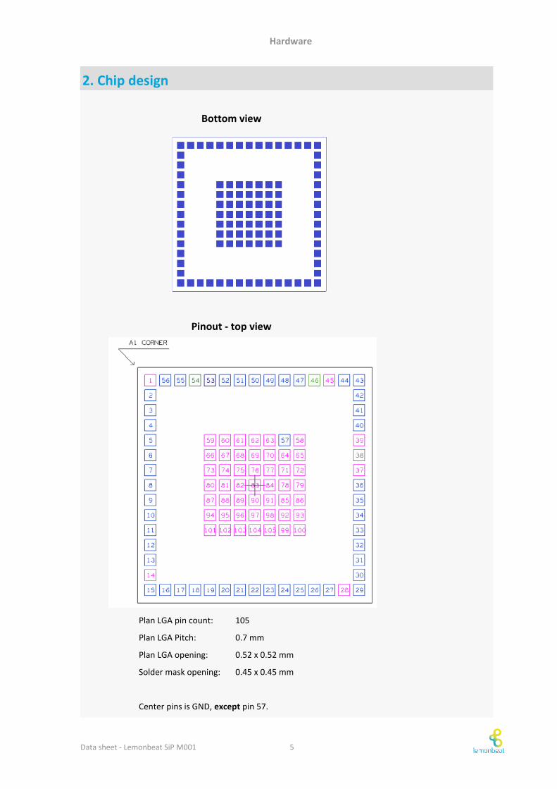
105
0.7 mm
0.52 x 0.52 mm
0.45 x 0.45 mm
Center pins is GND, except pin 57.
Bottom view
Pinout - top view
2. Chip design
Plan LGA pin count:
Plan LGA Pitch:
Plan LGA opening:
Solder mask opening:
Data sheet - Lemonbeat SiP M001 5
Hardware
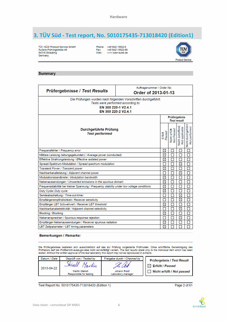
3. TÜV Süd - Test report, No. 5010175435-713018420 (Edition1)
Data sheet - Lemonbeat SiP M001 6
Hardware
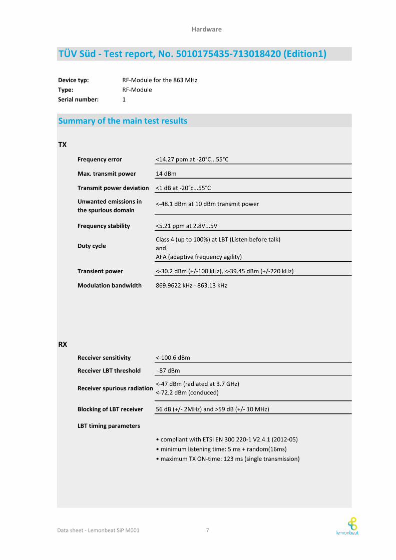
Device typ:
Type:
Serial number: 1
TX
<14.27 ppm at -20°C...55°C
Max. transmit power 14 dBm
Transmit power deviation <1 dB at -20°c...55°C
<-48.1 dBm at 10 dBm transmit power
Frequency stability <5.21 ppm at 2.8V...5V
Transient power <-30.2 dBm (+/-100 kHz), <-39.45 dBm (+/-220 kHz)
Modulation bandwidth 869.9622 kHz - 863.13 kHz
RX
<-100.6 dBm
Receiver LBT threshold -87 dBm
Receiver spurious radiation<-47 dBm (radiated at 3.7 GHz)
<-72.2 dBm (conduced)
56 dB (+/- 2MHz) and >59 dB (+/- 10 MHz)
LBT timing parameters
• compliant with ETSI EN 300 220-1 V2.4.1 (2012-05)
• minimum listening time: 5 ms + random(16ms)
• maximum TX ON-time: 123 ms (single transmission)
TÜV Süd - Test report, No. 5010175435-713018420 (Edition1)
Frequency error
Receiver sensitivity
Blocking of LBT receiver
Summary of the main test results
RF-Module for the 863 MHz
RF-Module
Class 4 (up to 100%) at LBT (Listen before talk)
and
AFA (adaptive frequency agility)
Duty cycle
Unwanted emissions in
the spurious domain
Data sheet - Lemonbeat SiP M001 7
Hardware
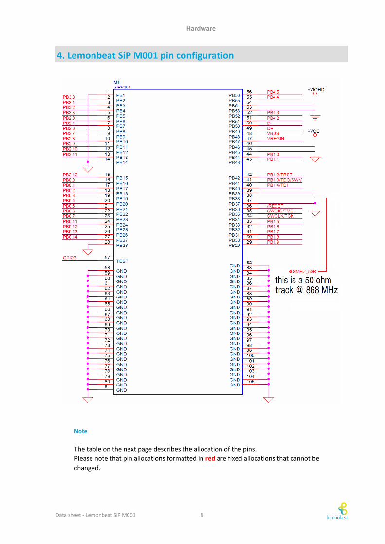
Note
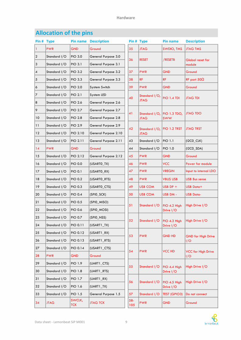
4. Lemonbeat SiP M001 pin configuration
The table on the next page describes the allocation of the pins.
Please note that pin allocations formatted in red are fixed allocations that cannot be
changed.
Data sheet - Lemonbeat SiP M001 8
Hardware
Pin # Type Pin name Description Pin # Type Pin name Description
1 PWR GND Ground 35 JTAG SWDIO, TMS JTAG TMS
2 Standard I/O PIO 3.0 General Purpose 3.0
3 Standard I/O PIO 3.1 General Purpose 3.1
4 Standard I/O PIO 3.2 General Purpose 3.2 37 PWR GND Ground
5 Standard I/O PIO 3.3 General Purpose 3.3 38 RF RF RF port 50Ω
6 Standard I/O PIO 2.0 System Switch 39 PWR GND Ground
7 Standard I/O PIO 2.1 System LED
8 Standard I/O PIO 2.6 General Purpose 2.6
9 Standard I/O PIO 2.7 General Purpose 2.7
10 Standard I/O PIO 2.8 General Purpose 2.8
11 Standard I/O PIO 2.9 General Purpose 2.9
12 Standard I/O PIO 2.10 General Purpose 2.10
13 Standard I/O PIO 2.11 General Purpose 2.11 43 Standard I/O PIO 1.1 (I2C0_CLK)
14 PWR GND Ground 44 Standard I/O PIO 1.0 (I2C0_SDA)
15 Standard I/O PIO 2.12 General Purpose 2.12 45 PWR GND Ground
16 Standard I/O PIO 0.0 (USART0_TX) 46 PWR VCC Power for module
17 Standard I/O PIO 0.1 (USART0_RX) 47 PWR VREGIN Input to internal LDO
18 Standard I/O PIO 0.2 (USART0_RTS) 48 PWR VBUS USB USB Bus sense
19 Standard I/O PIO 0.3 (USART0_CTS) 49 USB COM USB DP + USB Data+
20 Standard I/O PIO 0.4 (SPI0_SCK) 50 USB COM USB DM - USB Data-
21 Standard I/O PIO 0.5 (SPI0_MISO)
22 Standard I/O PIO 0.6 (SPI0_MOSI)
23 Standard I/O PIO 0.7 (SPI0_NSS)
24 Standard I/O PIO 0.11 (USART1_TX)
25 Standard I/O PIO 0.12 (USART1_RX)
26 Standard I/O PIO 0.13 (USART1_RTS)
27 Standard I/O PIO 0.14 (USART1_CTS)
28 PWR GND Ground
29 Standard I/O PIO 1.9 (UART1_CTS)
30 Standard I/O PIO 1.8 (UART1_RTS)
31 Standard I/O PIO 1.7 (UART1_RX)
32 Standard I/O PIO 1.6 (UART1_TX)
33 Standard I/O PIO 1.5 General Purpose 1.5 57 Standard I/O TEST (GPIO3) Do not connect
34 JTAGSWCLK,
TCKJTAG TCK
58-
105PWR GND Ground
Allocation of the pins
55 Standard I/O PIO 4.4 High
Drive I/O
High Drive I/O
PIO 4.2 High
Drive I/O
High Drive I/O
52 Standard I/O PIO 4.3 High
Drive I/O
High Drive I/O
PIO 1.3 TDO,
SWW
JTAG TDO
JTAG TDI
41 Standard I/O,
JTAG
56 Standard I/O PIO 4.5 High
Drive I/O
High Drive I/O
GND HD GND for High Drive
I/O
54 PWR VCC HD VCC for High Drive
I/O
51 Standard I/O
53 PWR
42 Standard I/O,
JTAG
PIO 1.2 TRST JTAG TRST
36 RESET /RESETB Global reset for
module
40Standard I/O,
JTAGPIO 1.4 TDI
Data sheet - Lemonbeat SiP M001 9
Hardware
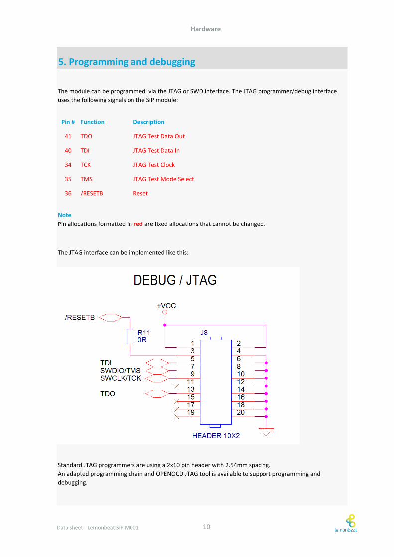
Pin # Function Description
41 TDO JTAG Test Data Out
40 TDI JTAG Test Data In
34 TCK JTAG Test Clock
35 TMS JTAG Test Mode Select
36 /RESETB Reset
Standard JTAG programmers are using a 2x10 pin header with 2.54mm spacing.
An adapted programming chain and OPENOCD JTAG tool is available to support programming and
debugging.
5. Programming and debugging
The module can be programmed via the JTAG or SWD interface. The JTAG programmer/debug interface
uses the following signals on the SiP module:
Note
Pin allocations formatted in red are fixed allocations that cannot be changed.
The JTAG interface can be implemented like this:
Data sheet - Lemonbeat SiP M001 10
Hardware
Important note
1.
2.
1.
Further reference
Ensure that all components are stored in a controlled environment (constant
temperature) for at least 24 hours. For an optimal result, we recommend storing
them for 48 hours .
Subsequently, all components should have the optimal temperature and dryness.
This is crucial to get the same good soldering result for all components used.
First solder the components that need a higher temperature and then the
components that need a lower temperature (i. e., from hot to colder).
Heating phase
Increase the temperature slowly. If the temperature is raised too quickly, the chip
can become defected.
Please note that the optimal heating phase can vary from machine to machine.
lemonbeat GmbH recommends to follow the document IPC-7801 "Reflow Oven Process Control Standard",
published by Accociation Connecting Eletronics Industries (IPC).
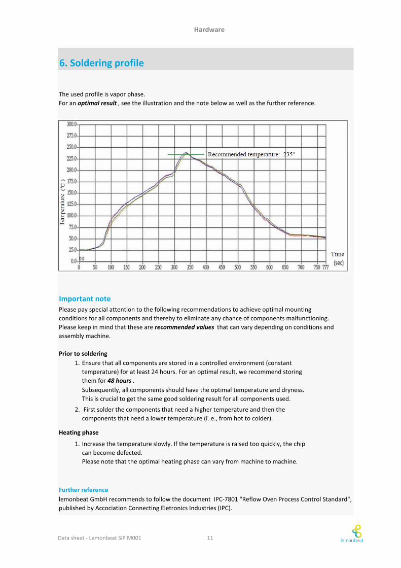
The used profile is vapor phase.
For an optimal result , see the illustration and the note below as well as the further reference.
6. Soldering profile
Please pay special attention to the following recommendations to achieve optimal mounting
conditions for all components and thereby to eliminate any chance of components malfunctioning.
Please keep in mind that these are recommended values that can vary depending on conditions and
assembly machine.
Prior to soldering
Data sheet - Lemonbeat SiP M001 11
Software
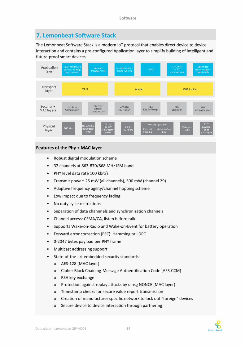
7. Lemonbeat Software Stack
• Robust digital modulation scheme
• 32 channels at 863-870/868 MHz ISM band
• PHY level data rate 100 kbit/s
• Transmit power: 25 mW (all channels), 500 mW (channel 29)
• Adaptive frequency agility/channel hopping scheme
• Low impact due to frequency fading
• No duty cycle restrictions
• Separation of data channnels and synchronization channels
• Channel access: CSMA/CA, listen before talk
• Supports Wake-on-Radio and Wake-on-Event for battery operation
• Forward error correction (FEC): Hamming or LDPC
• 0-2047 bytes payload per PHY frame
• Multicast addressing support
• State-of-the-art embedded security standards:
o AES-128 (MAC layer)
o Cipher Block Chaining-Message Authentification Code (AES-CCM)
o RSA key exchange
o Protection against replay attacks by uinsg NONCE (MAC layer)
o Timestamp checks for secure value report transmission
o Creation of manufacturer specific network to lock out "foreign" devices
o Secure device to device interaction through partnering
The Lemonbeat Software Stack is a modern IoT protocol that enables direct device to device
interaction and contains a pre-configured Application layer to simplify building of intelligent and
future-proof smart devices.
Features of the Phy + MAC layer
Data sheet - Lemonbeat SiP M001 12
Software
• Support of TCP and UDP
• Lemonbeat smart Device Language (LsDL) as XML API
• Based on well-known W3C standard: XML, XSD, EXI
• Low protocol overhead due to compressed XML (EXI) transmission
• Flexible and self-describing devices and services
• Highly reconfigurable at run-time
• Protocol suited for any scenario and application
• Independent of underlying layers, compatible with other transport media
• Service-oriented interface
• Closes gap between embedded firmware and high-layer software
• Definition of complex logics/user stories
• Network topology
o Device to device interaction
o Independent of central controller
Features of the Application layer
Note
Currently only UDP is supported for devices that use Wake-on-Radio or Event Listener
strategies.
Features of the Transport layer
Data sheet - Lemonbeat SiP M001 13
Software
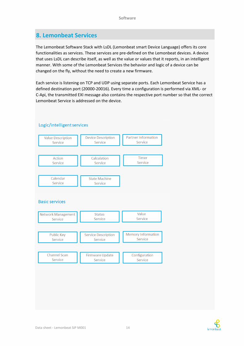
8. Lemonbeat Services
The Lemonbeat Software Stack with LsDL (Lemonbeat smart Device Language) offers its core
functionalities as services. These services are pre-defined on the Lemonbeat devices. A device
that uses LsDL can describe itself, as well as the value or values that it reports, in an intelligent
manner. With some of the Lemonbeat Services the behavior and logic of a device can be
changed on the fly, without the need to create a new firmware.
Each service is listening on TCP and UDP using separate ports. Each Lemonbeat Service has a
defined destination port (20000-20016). Every time a configuration is performed via XML- or
C-Api, the transmitted EXI message also contains the respective port number so that the correct
Lemonbeat Service is addressed on the device.
Data sheet - Lemonbeat SiP M001 14
Software
•
•
•
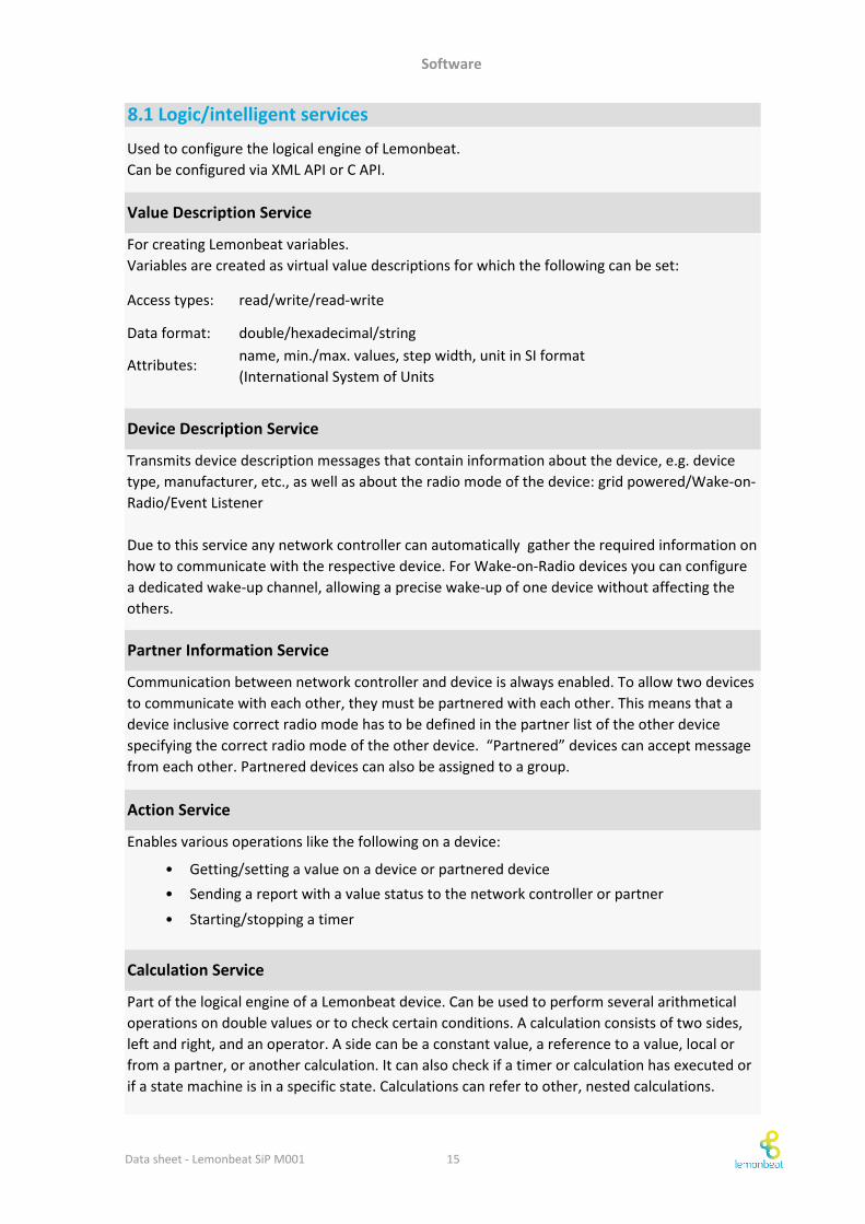
8.1 Logic/intelligent services
For creating Lemonbeat variables.
Variables are created as virtual value descriptions for which the following can be set:
Attributes:
read/write/read-write
double/hexadecimal/string
name, min./max. values, step width, unit in SI format
(International System of Units
Data format:
Access types:
Device Description Service
Enables various operations like the following on a device:
Getting/setting a value on a device or partnered device
Sending a report with a value status to the network controller or partner
Starting/stopping a timer
Value Description Service
Used to configure the logical engine of Lemonbeat.
Can be configured via XML API or C API.
Communication between network controller and device is always enabled. To allow two devices
to communicate with each other, they must be partnered with each other. This means that a
device inclusive correct radio mode has to be defined in the partner list of the other device
specifying the correct radio mode of the other device. “Partnered” devices can accept message
from each other. Partnered devices can also be assigned to a group.
Action Service
Part of the logical engine of a Lemonbeat device. Can be used to perform several arithmetical
operations on double values or to check certain conditions. A calculation consists of two sides,
left and right, and an operator. A side can be a constant value, a reference to a value, local or
from a partner, or another calculation. It can also check if a timer or calculation has executed or
if a state machine is in a specific state. Calculations can refer to other, nested calculations.
Transmits device description messages that contain information about the device, e.g. device
type, manufacturer, etc., as well as about the radio mode of the device: grid powered/Wake-on-
Radio/Event Listener
Due to this service any network controller can automatically gather the required information on
how to communicate with the respective device. For Wake-on-Radio devices you can configure
a dedicated wake-up channel, allowing a precise wake-up of one device without affecting the
others.
Partner Information Service
Calculation Service
Data sheet - Lemonbeat SiP M001 15
Software
•
•
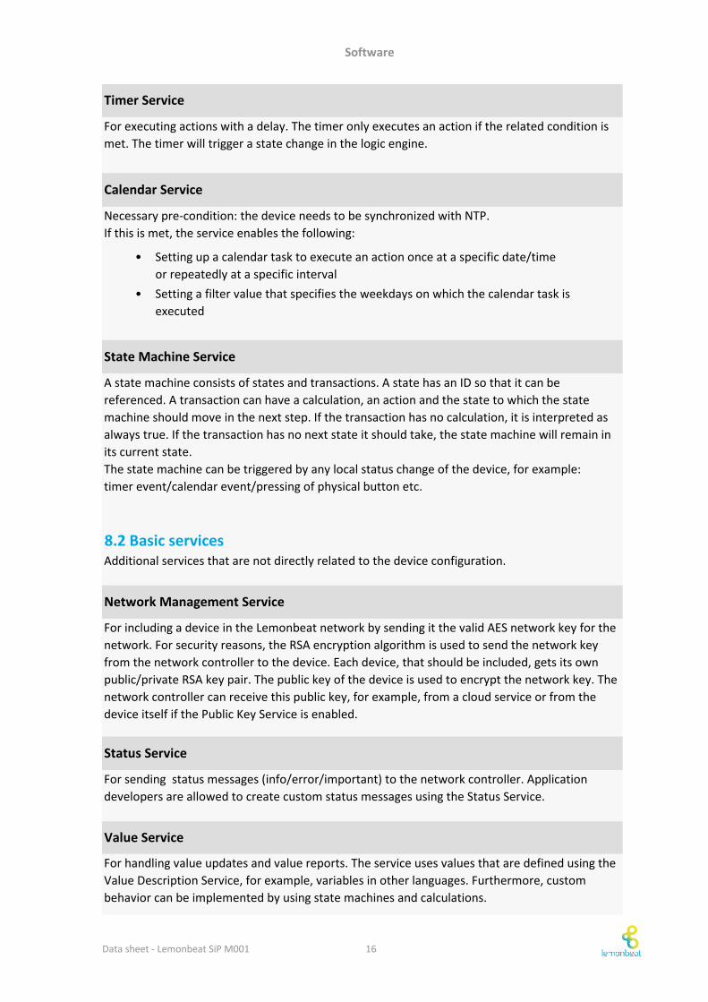
Additional services that are not directly related to the device configuration.
For including a device in the Lemonbeat network by sending it the valid AES network key for the
network. For security reasons, the RSA encryption algorithm is used to send the network key
from the network controller to the device. Each device, that should be included, gets its own
public/private RSA key pair. The public key of the device is used to encrypt the network key. The
network controller can receive this public key, for example, from a cloud service or from the
device itself if the Public Key Service is enabled.
8.2 Basic services
For handling value updates and value reports. The service uses values that are defined using the
Value Description Service, for example, variables in other languages. Furthermore, custom
behavior can be implemented by using state machines and calculations.
Value Service
Network Management Service
Setting up a calendar task to execute an action once at a specific date/time
or repeatedly at a specific interval
Setting a filter value that specifies the weekdays on which the calendar task is
executed
For executing actions with a delay. The timer only executes an action if the related condition is
met. The timer will trigger a state change in the logic engine.
For sending status messages (info/error/important) to the network controller. Application
developers are allowed to create custom status messages using the Status Service.
Timer Service
Calendar Service
State Machine Service
Status Service
Necessary pre-condition: the device needs to be synchronized with NTP.
If this is met, the service enables the following:
A state machine consists of states and transactions. A state has an ID so that it can be
referenced. A transaction can have a calculation, an action and the state to which the state
machine should move in the next step. If the transaction has no calculation, it is interpreted as
always true. If the transaction has no next state it should take, the state machine will remain in
its current state.
The state machine can be triggered by any local status change of the device, for example:
timer event/calendar event/pressing of physical button etc.
Data sheet - Lemonbeat SiP M001 16
Software
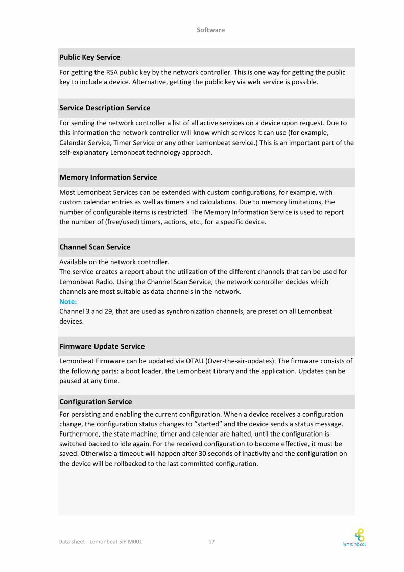
Public Key Service
For persisting and enabling the current configuration. When a device receives a configuration
change, the configuration status changes to “started” and the device sends a status message.
Furthermore, the state machine, timer and calendar are halted, until the configuration is
switched backed to idle again. For the received configuration to become effective, it must be
saved. Otherwise a timeout will happen after 30 seconds of inactivity and the configuration on
the device will be rollbacked to the last committed configuration.
For sending the network controller a list of all active services on a device upon request. Due to
this information the network controller will know which services it can use (for example,
Calendar Service, Timer Service or any other Lemonbeat service.) This is an important part of the
self-explanatory Lemonbeat technology approach.
Memory Information Service
Most Lemonbeat Services can be extended with custom configurations, for example, with
custom calendar entries as well as timers and calculations. Due to memory limitations, the
number of configurable items is restricted. The Memory Information Service is used to report
the number of (free/used) timers, actions, etc., for a specific device.
Channel Scan Service
Lemonbeat Firmware can be updated via OTAU (Over-the-air-updates). The firmware consists of
the following parts: a boot loader, the Lemonbeat Library and the application. Updates can be
paused at any time.
Configuration Service
Firmware Update Service
Available on the network controller.
The service creates a report about the utilization of the different channels that can be used for
Lemonbeat Radio. Using the Channel Scan Service, the network controller decides which
channels are most suitable as data channels in the network.
Note:
Channel 3 and 29, that are used as synchronization channels, are preset on all Lemonbeat
devices.
For getting the RSA public key by the network controller. This is one way for getting the public
key to include a device. Alternative, getting the public key via web service is possible.
Service Description Service
Data sheet - Lemonbeat SiP M001 17
© Copyright Lemonbeat GmbH. All rights reserved.
Disclaimer
Our logo, our name and lemonbeat are trademarks or registered
trademarks of lemonbeat GmbH. All other brand and product names
may be the trademarks of their companies. Lemonbeat GmbH reserves
the right to make changes to this document and its products at any time
without notice. Lemonbeat GmbH assumes no responsibility for any
errors that may appear in this document. The data contained herein
represents lemonbeat GmbH’s best data and/or estimates at the time
of issuance. Lemonbeat GmbH reserves the right to change or correct
this data at any time, without notice. If the product described herein is
under development, significant changes to these specifications are
possible. The information in this product data sheet is intended to be
general descriptive information for potential customers and users, and
is not intended to operate as, or provide, any guarantee or warrantee
to any user or customer. Lemonbeat GmbH does not assume any
responsibility or liability arising out of the application or use of any
product described herein, and disclaims any express or implied
warranties related to the sale and/or use of lemonbeat GmbH products
including liability or warranties related to fitness for a particular
purpose, merchantability, or infringement of any intellectual property
rights, except as express agreed to in lemonbeat GmbH’s Terms and
Conditions of sale (which are available from lemonbeat GmbH). All sales
of lemonbeat GmbH products are made exclusively according to
lemonbeat GmbH’s Terms and Conditions of Sale. The purchase of
products from lemonbeat GmbH does not convey a license under any
patent rights, copyrights, mask works rights, trademarks, or any other
intellectual property rights of lemonbeat GmbH or third parties.
Lemonbeat GmbH does not authorize its products for use as critical
components in life-supporting systems where a malfunction or failure
may reasonably be expected to result in significant injury to the user,
Top Related