


Languages
Pages
Legal

September, 2015 Page 1 of 8
LED Display Backlighting – Monitor Applications using 6-lead MULTILED®
Application Note
Abstract
This application note describes two reference designs for LCD backlighting using the 6-lead MULTILED® LRTB G6SG. The feasibility of the designs is shown on two LCD sizes of 19” and 24” with a typical brightness of 250cd/m² required for office applications.
The uniform illumination of very large screens used in LCD televisions which require a typical brightness of 350-500cd/m² is described in a separate application note "LED Display Backlighting – Large Screen and TV Application".
This document builds upon the fundamental concepts of LED backlighting described in the application note "LEDs, New Light Sources for Display Backlighting“.
Introduction
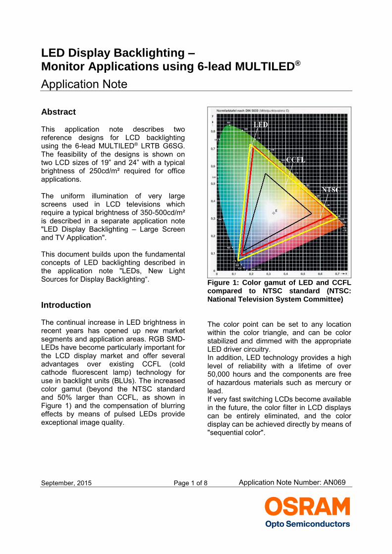
The continual increase in LED brightness in recent years has opened up new market segments and application areas. RGB SMD-LEDs have become particularly important for the LCD display market and offer several advantages over existing CCFL (cold cathode fluorescent lamp) technology for use in backlight units (BLUs). The increased color gamut (beyond the NTSC standard and 50% larger than CCFL, as shown in Figure 1) and the compensation of blurring effects by means of pulsed LEDs provide exceptional image quality.
Figure 1: Color gamut of LED and CCFL compared to NTSC standard (NTSC: National Television System Committee)
The color point can be set to any location within the color triangle, and can be color stabilized and dimmed with the appropriate LED driver circuitry. In addition, LED technology provides a high level of reliability with a lifetime of over 50,000 hours and the components are free of hazardous materials such as mercury or lead. If very fast switching LCDs become available in the future, the color filter in LCD displays can be entirely eliminated, and the color display can be achieved directly by means of "sequential color".
Application Note Number: AN069
September, 2015 Page 2 of 8
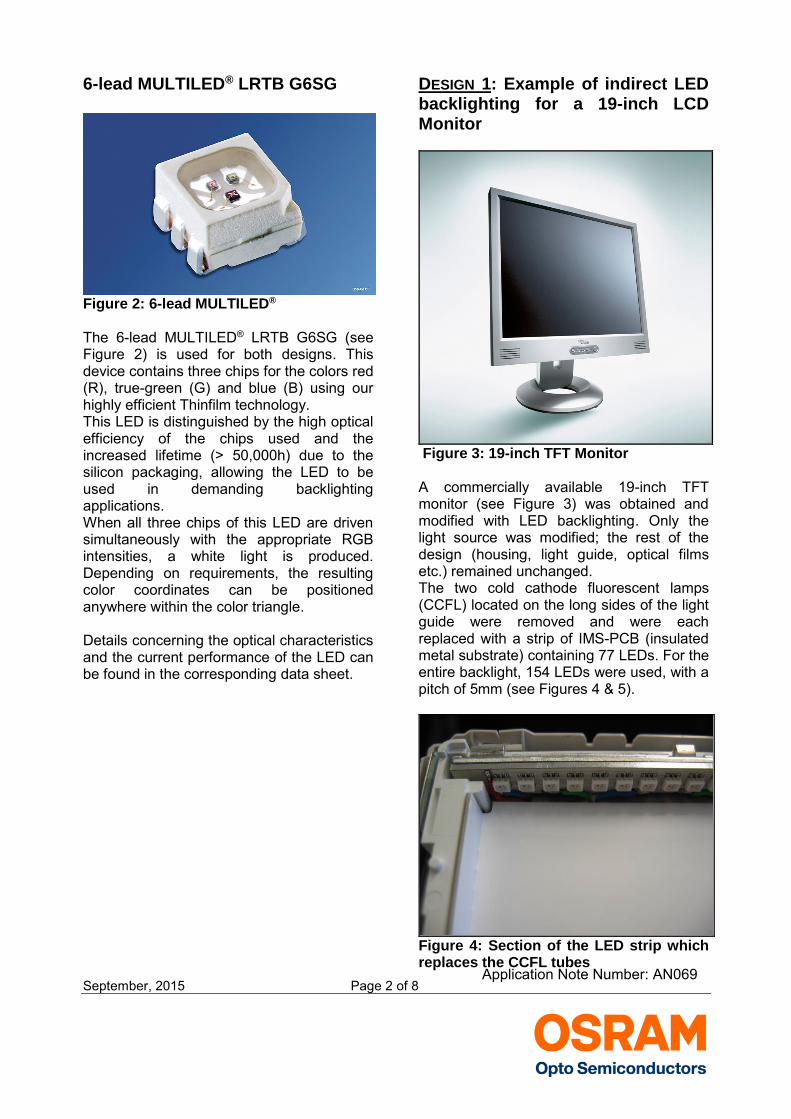
6-lead MULTILED® LRTB G6SG
Figure 2: 6-lead MULTILED®
The 6-lead MULTILED® LRTB G6SG (see Figure 2) is used for both designs. This device contains three chips for the colors red (R), true-green (G) and blue (B) using our highly efficient Thinfilm technology. This LED is distinguished by the high optical efficiency of the chips used and the increased lifetime (> 50,000h) due to the silicon packaging, allowing the LED to be used in demanding backlighting applications. When all three chips of this LED are driven simultaneously with the appropriate RGB intensities, a white light is produced. Depending on requirements, the resulting color coordinates can be positioned anywhere within the color triangle. Details concerning the optical characteristics and the current performance of the LED can be found in the corresponding data sheet.
DESIGN 1: Example of indirect LED backlighting for a 19-inch LCD Monitor
Figure 3: 19-inch TFT Monitor A commercially available 19-inch TFT monitor (see Figure 3) was obtained and modified with LED backlighting. Only the light source was modified; the rest of the design (housing, light guide, optical films etc.) remained unchanged. The two cold cathode fluorescent lamps (CCFL) located on the long sides of the light guide were removed and were each replaced with a strip of IMS-PCB (insulated metal substrate) containing 77 LEDs. For the entire backlight, 154 LEDs were used, with a pitch of 5mm (see Figures 4 & 5).
Figure 4: Section of the LED strip which replaces the CCFL tubes
Application Note Number: AN069
September, 2015 Page 3 of 8
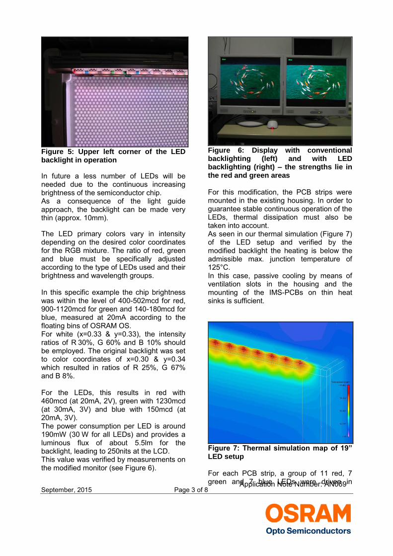
Figure 5: Upper left corner of the LED backlight in operation
In future a less number of LEDs will be needed due to the continuous increasing brightness of the semiconductor chip. As a consequence of the light guide approach, the backlight can be made very thin (approx. 10mm).
The LED primary colors vary in intensity depending on the desired color coordinates for the RGB mixture. The ratio of red, green and blue must be specifically adjusted according to the type of LEDs used and their brightness and wavelength groups. In this specific example the chip brightness was within the level of 400-502mcd for red, 900-1120mcd for green and 140-180mcd for blue, measured at 20mA according to the floating bins of OSRAM OS. For white (x=0.33 & y=0.33), the intensity ratios of R 30%, G 60% and B 10% should be employed. The original backlight was set to color coordinates of x=0.30 & y=0.34 which resulted in ratios of R 25%, G 67% and B 8%. For the LEDs, this results in red with 460mcd (at 20mA, 2V), green with 1230mcd (at 30mA, 3V) and blue with 150mcd (at 20mA, 3V). The power consumption per LED is around 190mW (30 W for all LEDs) and provides a luminous flux of about 5.5lm for the backlight, leading to 250nits at the LCD. This value was verified by measurements on the modified monitor (see Figure 6).
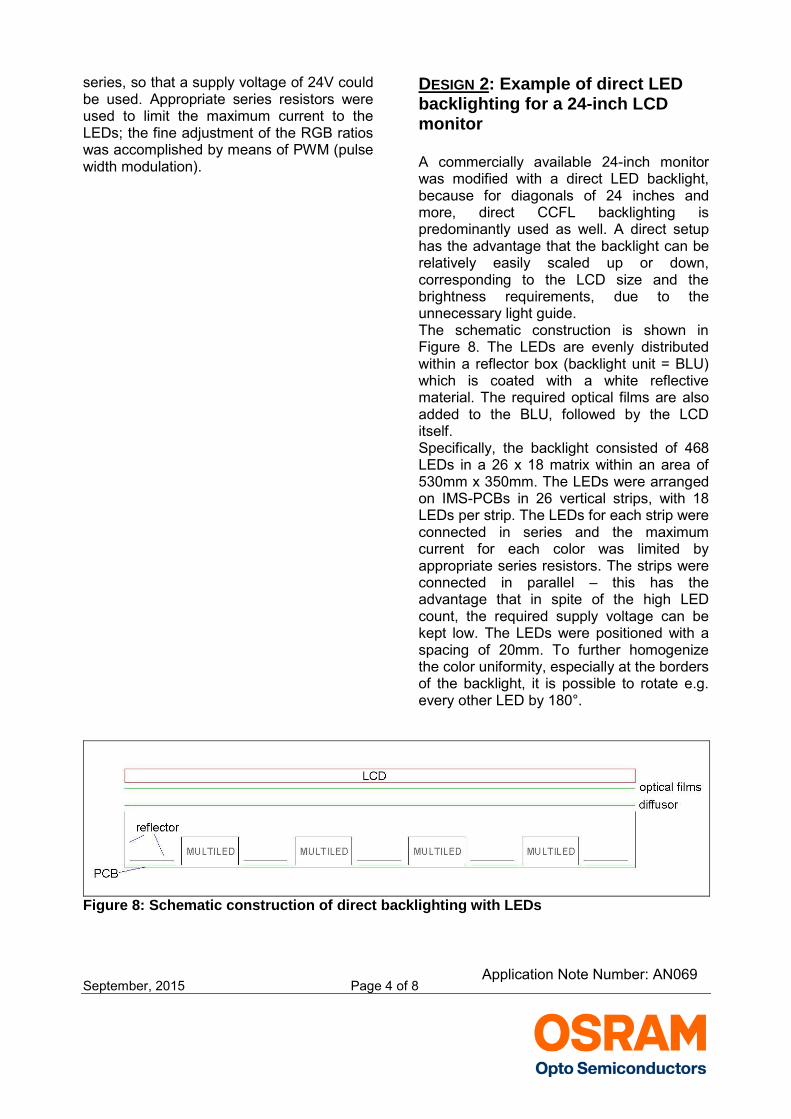
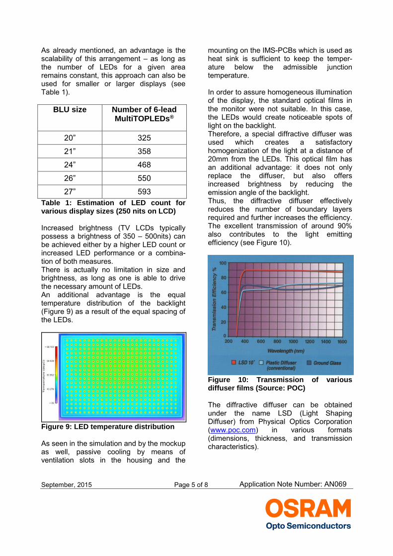
Figure 6: Display with conventional backlighting (left) and with LED backlighting (right) – the strengths lie in the red and green areas For this modification, the PCB strips were mounted in the existing housing. In order to guarantee stable continuous operation of the LEDs, thermal dissipation must also be taken into account. As seen in our thermal simulation (Figure 7) of the LED setup and verified by the modified backlight the heating is below the admissible max. junction temperature of 125°C. In this case, passive cooling by means of ventilation slots in the housing and the mounting of the IMS-PCBs on thin heat sinks is sufficient.
Figure 7: Thermal simulation map of 19” LED setup For each PCB strip, a group of 11 red, 7 green and 7 blue LEDs were driven in Application Note Number: AN069
September, 2015 Page 4 of 8
series, so that a supply voltage of 24V could be used. Appropriate series resistors were used to limit the maximum current to the LEDs; the fine adjustment of the RGB ratios was accomplished by means of PWM (pulse width modulation).
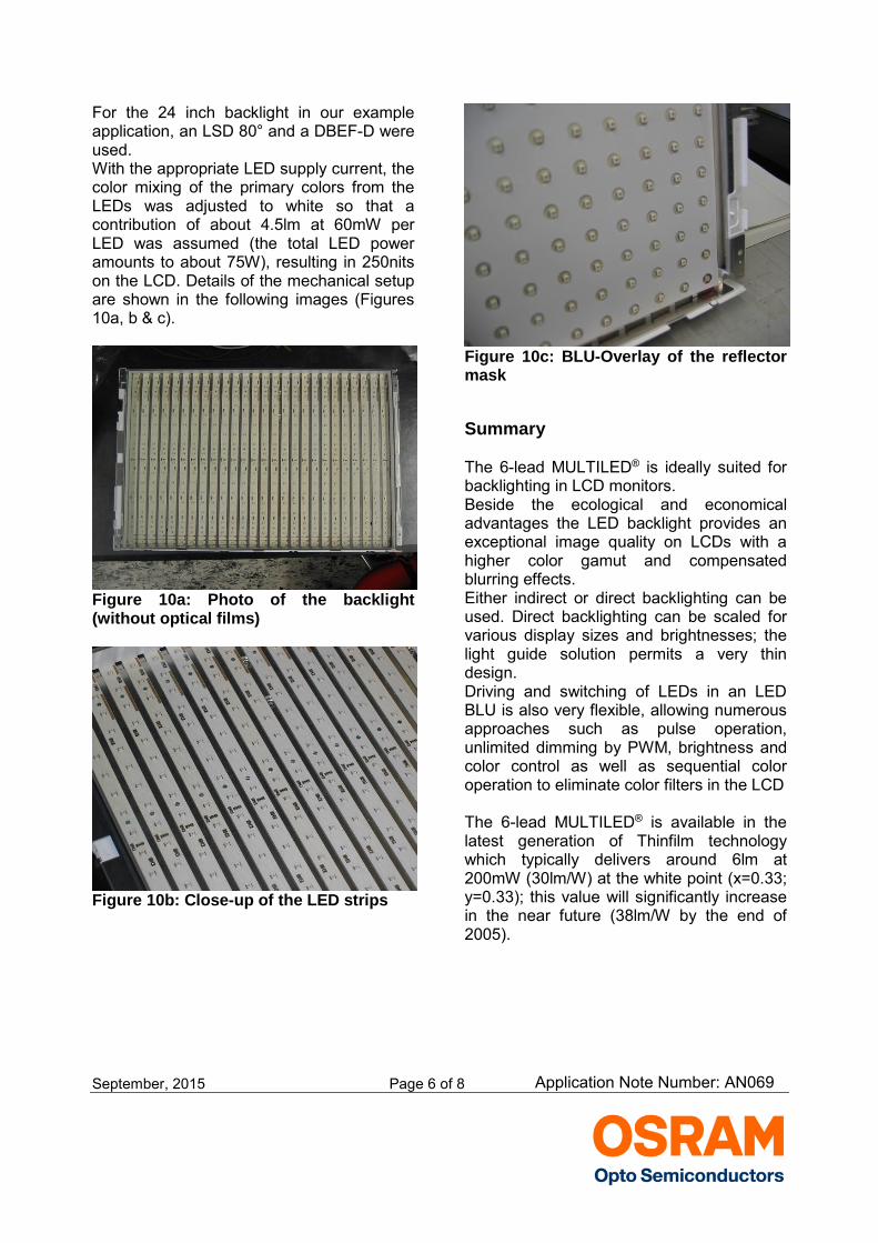
DESIGN 2: Example of direct LED backlighting for a 24-inch LCD monitor A commercially available 24-inch monitor was modified with a direct LED backlight, because for diagonals of 24 inches and more, direct CCFL backlighting is predominantly used as well. A direct setup has the advantage that the backlight can be relatively easily scaled up or down, corresponding to the LCD size and the brightness requirements, due to the unnecessary light guide. The schematic construction is shown in Figure 8. The LEDs are evenly distributed within a reflector box (backlight unit = BLU) which is coated with a white reflective material. The required optical films are also added to the BLU, followed by the LCD itself. Specifically, the backlight consisted of 468 LEDs in a 26 x 18 matrix within an area of 530mm x 350mm. The LEDs were arranged on IMS-PCBs in 26 vertical strips, with 18 LEDs per strip. The LEDs for each strip were connected in series and the maximum current for each color was limited by appropriate series resistors. The strips were connected in parallel – this has the advantage that in spite of the high LED count, the required supply voltage can be kept low. The LEDs were positioned with a spacing of 20mm. To further homogenize the color uniformity, especially at the borders of the backlight, it is possible to rotate e.g. every other LED by 180°.
Figure 8: Schematic construction of direct backlighting with LEDs
Application Note Number: AN069
September, 2015 Page 5 of 8
As already mentioned, an advantage is the scalability of this arrangement – as long as the number of LEDs for a given area remains constant, this approach can also be used for smaller or larger displays (see Table 1).
BLU size Number of 6-lead MultiTOPLEDs®
20” 325
21” 358
24” 468
26” 550
27” 593 Table 1: Estimation of LED count for various display sizes (250 nits on LCD) Increased brightness (TV LCDs typically possess a brightness of 350 – 500nits) can be achieved either by a higher LED count or increased LED performance or a combina-tion of both measures. There is actually no limitation in size and brightness, as long as one is able to drive the necessary amount of LEDs. An additional advantage is the equal temperature distribution of the backlight (Figure 9) as a result of the equal spacing of the LEDs.
Figure 9: LED temperature distribution As seen in the simulation and by the mockup as well, passive cooling by means of ventilation slots in the housing and the
mounting on the IMS-PCBs which is used as heat sink is sufficient to keep the temper-ature below the admissible junction temperature. In order to assure homogeneous illumination of the display, the standard optical films in the monitor were not suitable. In this case, the LEDs would create noticeable spots of light on the backlight. Therefore, a special diffractive diffuser was used which creates a satisfactory homogenization of the light at a distance of 20mm from the LEDs. This optical film has an additional advantage: it does not only replace the diffuser, but also offers increased brightness by reducing the emission angle of the backlight. Thus, the diffractive diffuser effectively reduces the number of boundary layers required and further increases the efficiency. The excellent transmission of around 90% also contributes to the light emitting efficiency (see Figure 10).
Figure 10: Transmission of various diffuser films (Source: POC) The diffractive diffuser can be obtained under the name LSD (Light Shaping Diffuser) from Physical Optics Corporation (www.poc.com) in various formats (dimensions, thickness, and transmission characteristics).
Application Note Number: AN069
September, 2015 Page 6 of 8
For the 24 inch backlight in our example application, an LSD 80° and a DBEF-D were used. With the appropriate LED supply current, the color mixing of the primary colors from the LEDs was adjusted to white so that a contribution of about 4.5lm at 60mW per LED was assumed (the total LED power amounts to about 75W), resulting in 250nits on the LCD. Details of the mechanical setup are shown in the following images (Figures 10a, b & c).
Figure 10a: Photo of the backlight (without optical films)
Figure 10b: Close-up of the LED strips
Figure 10c: BLU-Overlay of the reflector mask Summary The 6-lead MULTILED® is ideally suited for backlighting in LCD monitors. Beside the ecological and economical advantages the LED backlight provides an exceptional image quality on LCDs with a higher color gamut and compensated blurring effects. Either indirect or direct backlighting can be used. Direct backlighting can be scaled for various display sizes and brightnesses; the light guide solution permits a very thin design. Driving and switching of LEDs in an LED BLU is also very flexible, allowing numerous approaches such as pulse operation, unlimited dimming by PWM, brightness and color control as well as sequential color operation to eliminate color filters in the LCD The 6-lead MULTILED® is available in the latest generation of Thinfilm technology which typically delivers around 6lm at 200mW (30lm/W) at the white point (x=0.33; y=0.33); this value will significantly increase in the near future (38lm/W by the end of 2005).
Application Note Number: AN069
September, 2015 Page 7 of 8
Appendix Links to manufacturers: http://www.poc.com/ (light shaping diffuser from POC) http://www.kimoto.ch/ (diffuser and reflective film from Kimoto) http://cms.3m.com/cms/US/en/2-136/izezrFG/view.jhtml (optical films from 3M)
Don't forget: LED Light for you is your place to be whenever you are looking for information or worldwide partners for your LED lighting project.
www.ledlightforyou.com Revision History
Date Revision History
May 2005 Publishing of Application Note Sept. 2015 Change of Company Info & Disclaimer
Authors: Josef Hüttner ABOUT OSRAM OPTO SEMICONDUCTORS OSRAM, Munich, Germany is one of the two leading light manufacturers in the world. Its subsidiary, OSRAM Opto Semiconductors GmbH in Regensburg (Germany), offers its customers solutions based on semiconductor technology for lighting, sensor and visualization applications. OSRAM Opto Semiconductors has production sites in Regensburg (Germany), Penang (Malaysia) and Wuxi (China). Its headquarters for North America is in Sunnyvale (USA), and for Asia in Hong Kong. OSRAM Opto Semiconductors also has sales offices throughout the world. For more information go to www.osram-os.com.
Application Note Number: AN069
September, 2015 Page 8 of 8
DISCLAIMER PLEASE CAREFULLY READ THE BELOW TERMS AND CONDITIONS BEFORE USING THE INFORMATION SHOWN HEREIN. IF YOU DO NOT AGREE WITH ANY OF THESE TERMS AND CONDITIONS, DO NOT USE THE INFORMATION. The information provided in this general information document was formulated using the utmost care; however, it is provided by OSRAM Opto Semiconductors GmbH on an “as is” basis. Thus, OSRAM Opto Semiconductors GmbH does not expressly or implicitly assume any warranty or liability whatsoever in relation to this information, including – but not limited to – warranties for correctness, completeness, marketability, fitness for any specific purpose, title, or non-infringement of rights. In no event shall OSRAM Opto Semiconductors GmbH be liable – regardless of the legal theory – for any direct, indirect, special, incidental, exemplary, consequential, or punitive damages arising from the use of this information. This limitation shall apply even if OSRAM Opto Semiconductors GmbH has been advised of possible damages. As some jurisdictions do not allow the exclusion of certain warranties or limitations of liabilities, the above limitations and exclusions might not apply. In such cases, the liability of OSRAM Opto Semiconductors GmbH is limited to the greatest extent permitted in law. OSRAM Opto Semiconductors GmbH may change the provided information at any time without giving notice to users and is not obliged to provide any maintenance or support related to the provided information. The provided information is based on special conditions, which means that the possibility of changes cannot be precluded. Any rights not expressly granted herein are reserved. Other than the right to use the information provided in this document, no other rights are granted nor shall any obligations requiring the granting of further rights be inferred. Any and all rights and licenses regarding patents and patent applications are expressly excluded. It is prohibited to reproduce, transfer, distribute, or store all or part of the content of this document in any form without the prior written permission of OSRAM Opto Semiconductors GmbH unless required to do so in accordance with applicable law.
Application Note Number: AN069
Top Related