


![Application Brochure A265 - Patriot Supply1].pdf · Electrical Essential Control Settings ... 115 V (ac) Class II Transformer L Do not apply power 12 13 Com – 5A 5A 5A 5A 5A 5A](https://static.fdocuments.in/doc/165x107/5eaeca02e603423ba506622e/application-brochure-a265-patriot-1pdf-electrical-essential-control-settings.jpg)


Languages
Pages
Legal


Lecture 5a: Sequence Interaction Diagrams
CSE 111
Copyright W. Howden 1

Where we are now
• Use Cases• description of required system functionality
• System architecture• overall picture of what system will look like
• Domain analysis• basic concepts and relationships that will become
foundational classes
• incipient transformation of functional use cases into object oriented design
Copyright W. Howden 2

What’s next?
• Determine the interactions between the actors and the system
• Determine the interactions between the subsystem components– defines the subsystem interfaces– we will use Sequence Interaction Diagrams
Copyright W. Howden 3
Copyright W. Howden 4
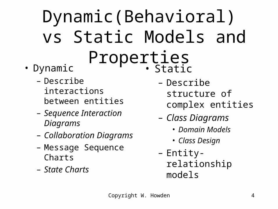
Dynamic(Behavioral) vs Static Models and Properties
• Dynamic– Describe interactions
between entities
– Sequence Interaction Diagrams
– Collaboration Diagrams
– Message Sequence Charts
– State Charts
• Static– Describe structure of
complex entities
– Class Diagrams• Domain Models
• Class Design
– Entity-relationship models

Copyright W. Howden 5
Sequence Diagrams - Notation
• Object boxes– actors, subsystems, class instances
• Life lines– vertical line extending down from object
• Messages– horizontal arrows from one life line to another– One object sends a message to another message

Sequence Diagrams - Meaning
• Each diagram describes a scenario, or what happens during a use of the system
• A system can be described by a collection of SI diagrams
Copyright W. Howden 6

Copyright W. Howden 7

Comments on Diagrams - 1
• No two message arrows should be at the same horizontal level. The ordering down the page shows the time order
• If a message has a return, you do not show it as a solid back arrow. Either leave the arrow out, or show using a dashed message arrow (not used here)
Copyright W. Howden 8

Comments on Diagrams - 2
The boxes at the top stand for objects, not classes
• We can indicate which classes the objects come from, using the notation:GUI :DomainLogic :DataBase– This notation indicates an object from the GUI,
Domain Logic and DataBase classes
Copyright W. Howden 9
Comments on Diagrams - 3
• Boxes with top-right dog-ear can be used to insert explanatory notes in the SI diagram
• Little boxes in the middle of the life lines are drawn in by the graphics editor (e.g. MS Visio)
• can use them to indicate “focus of control”, which is discussed later
Copyright W. Howden 10

Copyright W. Howden 11
Comments on Diagram - 4• This SI Diagram shows:
– System/Actor interactions• Interactions of users with system
• Leads to user interface design features
– Subsystem interactions• Requirements elaboration and design
• How subsystems interact with each other
• Leads to subsystem interface design features

Copyright W. Howden 12
System/Actor Interactions
• Specifies the needed user interface forms– can be used to identify contents/capabilities of
GUI
• Following example: includes use of “self-messages” notation– used to show an internal action in an object (it
sends itself a message)• e.g. the actions taken by the GUI in response to a
user message

Copyright W. Howden 13

Use Cases and Sequence Diagrams
• Sequence diagrams can be used for different aspects of a design– in CSE 111 project restricted to subsystem
interactions caused by use case interactions
• Each use case may have one or more sequence interaction diagrams that describe possible scenarios of system usage
Copyright W. Howden 14

Copyright W. Howden 15
Subsystem Interactions
• Show the messages that the subsystems send back and forth
• Should conform to layers architecture– “higher levels” send messages to “lower levels”
but not vice versa
• Helps to define the subsystems interface details (what messages/methods the interface class must have, etc.)

Copyright W. Howden 16

Comments on Diagram - 1
• In the diagram we see the conditional notation– uses the notation “[cond]” which means that the
message only occurs if the condition is satisfied– if only [cond] is present, and there is no
[not(cond)] alternative in the diagram, it means this diagram only describes the scenario for the [cond] case
Copyright W. Howden 17

Comments on Diagrams - 2
• In our diagram, there are three subsystems: GUI, DomainLogic, and DataBase
• Each subsystem is a collection of classes, but has a single interface class through which all communication is channeled
• The names of the interface classes are the same as the subsystem names
Copyright W. Howden 18
Comments on Diagrams - 3
• We show, for example, the :DomainLogic object (an instance of the DomainLogic interface class) sending a message to :DataBase (an instance of the Domain Logic interface). The message will actually go to the DataBase interface, but it could come from class objects in the DomainLogic subsystem other than the interface class
Copyright W. Howden 19
Comments on Diagrams - 4- So, is it Illegal/Incorrect?
• At this early stage, we have identified our subsystems
• We can represent the subsystems with a single interface class that has all the required logic, etc.
• As the design proceeds we will identify additional classes in the subsystems
Copyright W. Howden 20

Copyright W. Howden 21
Some Additional Examples
• Get a Date Scenario
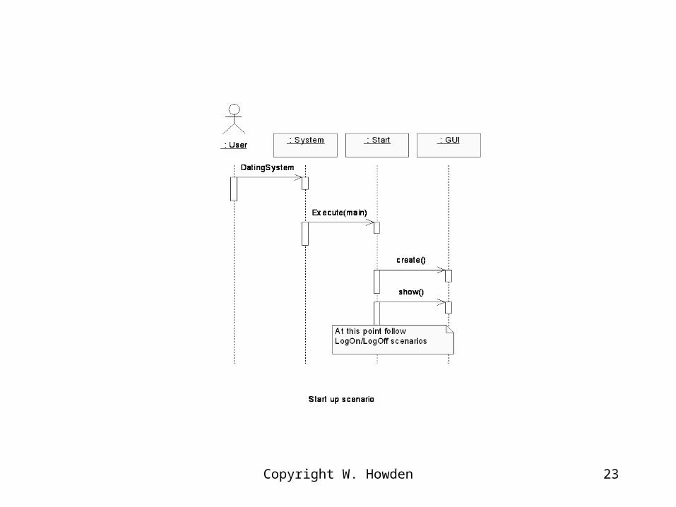
• Start up Scenario– Shows interactions with system
• Log On Scenario
• Exit/Log Off Scenario

22
Copyright W. Howden 23

24

Copyright W. Howden 25
Copyright W. Howden 26
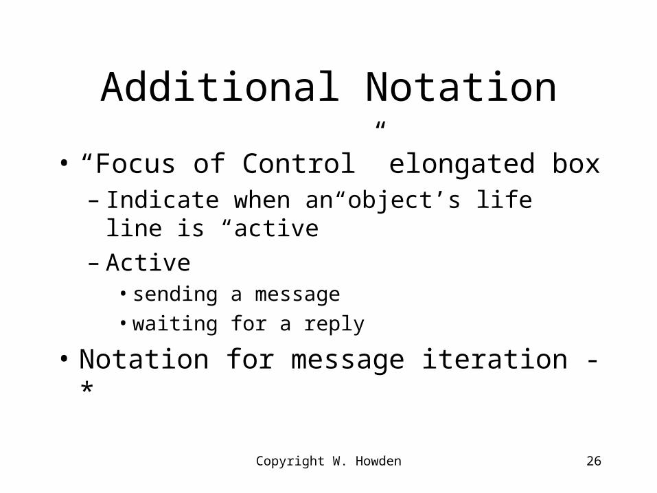
Additional Notation
• “Focus of Control” elongated box– Indicate when an object’s life line is “active”– Active
• sending a message
• waiting for a reply
• Notation for message iteration - *

Copyright W. Howden 27
: Member : GUI : DomainLogic : DataBase
getDate()
displayOptionChoice()
dsiplayDaterPreferencesForm()
daterPreferences()
getDate()
memberData:=getFirst()
memberData:=*getNext()
searchResult
[null] displaySorry()
[notNull] displayDateProps()
Copyright W. Howden 28
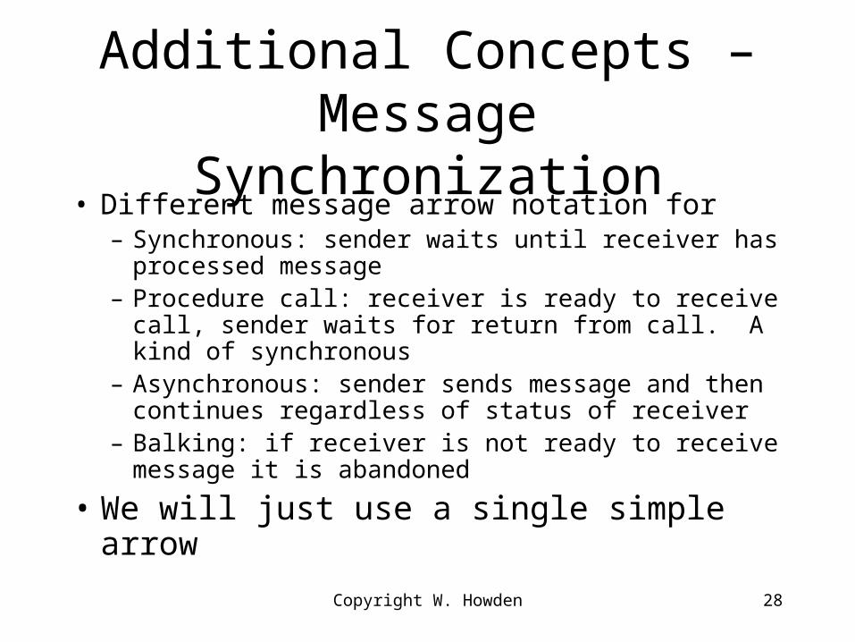
Additional Concepts – Message Synchronization
• Different message arrow notation for– Synchronous: sender waits until receiver has processed
message– Procedure call: receiver is ready to receive call, sender
waits for return from call. A kind of synchronous – Asynchronous: sender sends message and then
continues regardless of status of receiver– Balking: if receiver is not ready to receive message it is
abandoned
• We will just use a single simple arrow

New Design Information
• Design details for subsystem interface classes
• Messages received by the DomainLogic and the DataBase interfaces will be implemented as methods in those interface classes
• Messages to GUI correspond to GUI input forms
Copyright W. Howden 29
CSE 111 Deliverables to Date
• Uses cases for application, all functionality; identification of uses cases and functionality to be done in phase 1
• Domain model for phase 1
• System model (three tier); consideration of use of callbacks for project
• Interaction sequence diagrams showing actor/system interactions and diagrams showing subsystem interactions (New)
Copyright W. Howden 30
Top Related