


Languages
Pages
Legal


Interfacing Display with MPU without Peripheral Controller
Dr A SahuDept of Computer Science & Engineering
IIT Guwahati

Outline• Peripheral communications • Display• LED Display– Decoder – Generic model– Interfacing
• Character Display Monitor– Decoder– Generic Model
• Graphics monitor – Why graphics? Vector Vs Raster
• Keyboard type and Interfaces

Introduction
• Peripherals : HD monitor, 5.1 speaker • Interfaces : Intermediate Hardware – Nvidia GPU card, Creative Sound Blaster card
• Interfaces : Intermediate Software/Program– Nvidia GPU driver , Sound Blaster Driver software
Processor RAM

Transmission controller• Transmission Controller:– MPU control, Device Control (DMA)
• Type of IO mapping– Peripheral (IN/Out), Memory mapped IO (LD/ST,MV)
• Format of communication– Synchronous (T & R sync with clock), Asynchronous
• Mode of Data Transfer – Parallel, Serial (UART)
• Condition for data transfer – Uncond., Polling, Interrupt, Ready signal, Handshake

Display
7 Seg 9 Seg 16 Seg 3x5 DotMatix 5x7 9x11
Dot Matrix Display Panel 25x80 character monitor

Generic Model (Data) of Display
DataASCII/BCD
DecoderOr
Memory
Display
Monitor/LEDs
Time to Decode Time to Display

7 Segment LED Interfaces
• Data to 7 Segment Decoder
a
b
c
d
e
f
g
Common Cathode
a
b
c
f
g
e
d
D
C
B
A
LT
RBI
BI
Decoder
5V
1
0
0
0
1
01
1
10
1
5
5v
5V
1
11
1
11
1
5
5v
RBO

Multiple 7 Segment LED Interfaces
• Data to 7 Segment Decoder
a b c d e f g
D C B A
RBI RBO
a b c d e f g
D C B A
RBI RBO
a b c d e f g
D C B A
RBI RBO
a b c d e f g
D C B A
RBI RBO
a b c d e f g
D C B A
RBI RBO
5V
0 0 0 0 0 0 0 0 0 0 1 1 0 0 0 0 0 1 1 1
10
Blank
0
Blank
1 1

Multiplexed line and Memory use
40 Bit data line
8 Bit data line
0 1 2 3 4
Data 1 Data 2Data 3Data 4
Data 0
Mod 5 Counter

Multiplexed line/Memory used 7 Segment Decoder
1:N Decoder
Counter
RAM
590

Interface LED Display Using Delay
• Write a program to display contents of B,C,D and E register to LED display
• Write to buffer memory to display to 7 Seg. LEDs
• Use address FC H,FD H,FE H and FF H to display

Interface Diagram
LEDsBuffer
Memory
Address line
CS WR RD
Datalines
Ctr
7 Seg.Decoder
MPU
A7
A6
A5
A4
A3
A2
74LS373Latches
LED7
D6
D5
D4
D3
D2
D1
D0
A1
A0
IO/MRD
WR

Monitor program
• Interface program to Display content of B,C,D and E after 1 Sec Delay
DIS: MVI A,BOUT FCHMVI A,COUT FDHMVI A,DOUT FEHMVI A,EOUT FFHCALL DELAY ;1sec delay JMP DIS;

Multiplexed 25x80 Char Display
25x80 character monitor
C A T
F I R E
0 1 2 3 4 ….. 78 79012
2324
A
DecoderOr
ROMMemory
Decoded Bits
Row Ctr
ColCtr CLK > 50Hzx25x80

Generic Model of Char Monitor
• Delay of Monitor is 1/50 Sec, After Every 50 Second it makes ready
• From stream buffer it writes to Frame buffer after getting command. (Flush stream command)
Char FrameBuffer
Memory
Address line
CS WR
Datalines
Counter
Stream Buffer
When C=0Ready
Address (r,c)

Speed of Display• LED is very high speed – You can write to LEDs at very high speed– Display meant for to see some thing (Is it good?)
• 30 Frames/Sec is more then enough for human eye (>30 blink make human eye Fixed)
• No of blink > 30Hz – Human can not differentiate ON/OFF state, it will
be seen AS ON state• Video display make default 30-60 Frame/Sec• Monitor run at speed 30-60 Frame/Sec

Speed of Monitor and Disk
• Speed is fixed (60Frame/Sec)
• $ a.out• $ a.out > outputfile• $ a.out > /dev/null
for(i=0;i<10000;i++){printf(“HelloWorld”);
}

Migration from Char to Graphics/Video
• Char display (80x25 char, 5x7pixel=400x175)• CRT Monitor (400x600, 640x480,600x800)• LCD Monitor (1024x768,1280x1024,…)• Graphics visually more appealing • Display Line, Circle, Rectangle, Curve, Polygon– Character using this primitives– True type font
RED ARROWCircle

Multiplexed 1024x768 pixel display
1024x768 Pixel LCD
0 1 2 3 4 ….. …1023012
767
R
Row Ctr
ColCtr CLK > 1024x768x50Hz
B G8x3=24 Bits
Frame Buffer
Refresh screen 50 time a Sec

Frame Buffer (1 Bit Pixel): Grey
Pixels in Frame Buffer
1 Bit Per Pixels Pixels on the Screen
Graphical representation of 1 bit color

Frame Buffer (15 Bit Pixel)
Pixels in Frame Buffer
Pixels on the Screen
15 Bit Per Pixels
Graphical representation of 15 bit color

Frame Buffer (24 Bit Pixel)
Pixels in Frame Buffer
Pixels on the Screen
24 Bit Per Pixels
Graphical representation of 24 bit color

1bit, 8 bit & 16 bit color
1- bit color 8-bit color 16-bit color

Graphics
• Vector graphics: – Use geometrical primitives based
on mathematical equations, to represent images in computer graphics
– Points, Lines, Curve, shapes or Polygons
• Raster Graphics: Complementary to Vector Graphics– Representation of images as an
array of pixels – photographic images
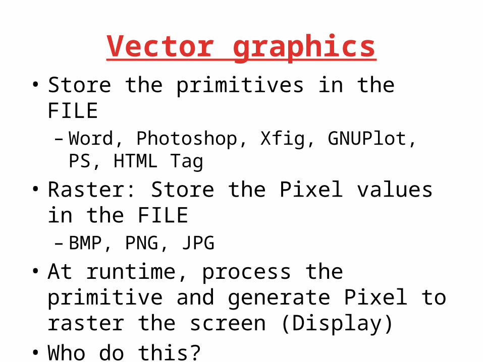
Vector graphics• Store the primitives in the FILE– Word, Photoshop, Xfig, GNUPlot, PS, HTML Tag
• Raster: Store the Pixel values in the FILE– BMP, PNG, JPG
• At runtime, process the primitive and generate Pixel to raster the screen (Display)
• Who do this?– Software – GPU (hardware accelerated routine)

Character Vs Font • Computer font formats: TrueType Font – Where each letter is created from Bézier curves
• Many varieties of font for a characterUnits
Points with unit and curve
properties are stored

Graphics Cards• GPU : specialized processor that accelerates
3D or 2D graphics primitives operations• Lots of Floating point operations• Accelerates Primitives – Line, circle, polygon, mesh, projection, sphere,

Graphics System 3D application
3D API: OpenGL
DirectX/3D
3D API Commands
CPU-GPU Boundary
GPU Command& Data Stream
GPU Command
PrimitiveAssembly
Rastereisation Interpolation
RasterOperation
Frame Buffer
Programmable Fragment Processors
ProgrammableVertex
Processor
Vertex Index Stream
Assembled polygon, line & points
Pixel Location Stream
Pixel Updates
Transformed Fragments
Rastorized PretransformedFragments
transformedVerticesPretransformed
Vertices

Graphics System
Memory System
Texture Memory
Frame Buffer
Vertex Processing
Pixel Processing
Vertices(x,y,z)
PixelR, G,B
Vertex Shadder
Pixel Shadder

Keyboard

Reference • R S Gaonkar, “Microprocessor Architecture”, Unit II preface,
Chapter 14 and 17

Thanks
Top Related