


Languages
Pages
Legal


LAPPEENRANTA UNIVERSITY OF TECHNOLOGY
School of Energy Systems
Energy Technology
Sergio Rafael Martinez Orozco
MOTOR TYPES COMPARISON DETERMINING EFFICIENCY IN PUMPING
SYSTEMS
Master’s thesis
2015
Examiners: Professor D.Sc. Jero Ahola, D.Sc. Tero Ahonen
Supervisor: D.Sc. Tero Ahonen
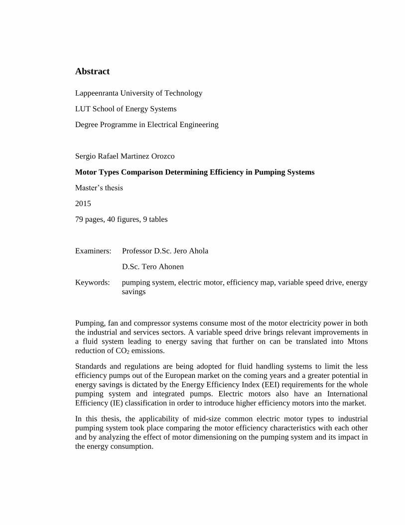
Abstract
Lappeenranta University of Technology
LUT School of Energy Systems
Degree Programme in Electrical Engineering
Sergio Rafael Martinez Orozco
Motor Types Comparison Determining Efficiency in Pumping Systems
Master’s thesis
2015
79 pages, 40 figures, 9 tables
Examiners: Professor D.Sc. Jero Ahola
D.Sc. Tero Ahonen
Keywords: pumping system, electric motor, efficiency map, variable speed drive, energy
savings
Pumping, fan and compressor systems consume most of the motor electricity power in both
the industrial and services sectors. A variable speed drive brings relevant improvements in
a fluid system leading to energy saving that further on can be translated into Mtons
reduction of CO2 emissions.
Standards and regulations are being adopted for fluid handling systems to limit the less
efficiency pumps out of the European market on the coming years and a greater potential in
energy savings is dictated by the Energy Efficiency Index (EEI) requirements for the whole
pumping system and integrated pumps. Electric motors also have an International
Efficiency (IE) classification in order to introduce higher efficiency motors into the market.
In this thesis, the applicability of mid-size common electric motor types to industrial
pumping system took place comparing the motor efficiency characteristics with each other
and by analyzing the effect of motor dimensioning on the pumping system and its impact in
the energy consumption.

Acknowledgements
This work was carried out at the Department of Electrical Engineering, LUT School of
Energy Systems at Lappeenranta University of technology during 2015.
I would like to thank my supervisor, Tero Ahonen for his guidance, constant feedback and
suggestions during the thesis work, always finding time to attend my inquiries. To
Professor Jero Ahola for his support and advice on the project. I am also thankful with
research director Markku Niemelä and junior researcher Juho Montonen for providing very
useful data and laboratory measurements.
I want to thank my mother Maria for being an exemplary person in all possible ways, my
sister Roxana for her unconditional help and hearten, my brothers Flavio and Edgardo for
their support. I am also very grateful with the family Chávez Orozco for sharing
unforgettable moments during our lives.
Special thanks to my friends in Lappeenranta Santeri Pöyhönen, Ivan Deviatkin, Michael
Child, Mariana Carvalho and Arun Narayanan for their help during my studies. To Anneke
van Giersbergen for her support and kindness. And to all my friends I have met from
different countries: Armenia, Brazil, Canada, China, Colombia, Finland, Germany, Ghana,
India, Iran, Nepal, Netherlands, Pakistan, Peru, Poland, Russia, Spain, Syria and Vietnam.
I am also grateful with my cousins Ivan Alatorre for encouraging me to start my studies
abroad, and Javier Farfan for making my adaptation to a new culture easy. Finally I would
like to thank to Claudia Cabrera, Enrique Lopez, to my friends from my hometown
Arandas, relatives and friends of the company I was working back in Mexico for supporting
me in different ways prior and during my studies.
Sergio Rafael Martinez Orozco
December 2015
Lappeenranta, Finland

Table of Contents
1 INTRODUCTION ........................................................................................................ 9
1.1 Background .............................................................................................................. 9
1.2 Motivation for the study ........................................................................................ 14
1.3 Objectives .............................................................................................................. 14
2 MOTOR COMPARISONS AND INDICATIVE RESULTS ................................. 16
2.1 Principles of electric motors .................................................................................. 16
2.2 Motor types under study and their construction .................................................... 18
2.2.1 Induction Motor ............................................................................................. 22
2.2.2 Permanent Magnet Synchronous Motor......................................................... 27
2.2.3 Synchronous Reluctance Motor ..................................................................... 33
2.2.4 Permanent Magnet-Assisted Synchronous Reluctance Motor ....................... 38
2.3 Comparison including different applications ........................................................ 41
2.4 High efficiency pump motors ................................................................................ 43
3 EVALUATION OF 15 KW MOTORS .................................................................... 47
3.1 Motor characteristics comparison.......................................................................... 47
3.2 Motor efficiency comparison ................................................................................ 49
3.3 Pumping system requirements ............................................................................... 54
3.3.1 Efficiency of 15 kW SynRM drive ................................................................ 60
3.3.2 Efficiency of induction motor drive ............................................................... 61
3.3.3 Effect of dimensioning on the SynRM efficiency.......................................... 63
3.4 Results for 15 kW motors ...................................................................................... 64
3.5 Potential of higher efficiency motors in the closed-loop application .................... 65
4 COMPARISON OF RESULTING ENERGY COSTS BETWEEN THE
STUDIED CASES .............................................................................................................. 68
5 CONCLUSIONS ........................................................................................................ 71
6 SUMMARY ................................................................................................................ 73
REFERENCES ................................................................................................................... 75

Abbreviations and symbols
Roman letters
 Peak current density [A/m]
B Magnetic flux density [V s/m2]
Peak magnetic flux density [V s/m2]
E Electric field strength [V/m]
f Frequency [Hz]
F Lorentz force [N], vector
H Head [m]
i Electric current [A]
𝑖𝑠 Stator current space vector
j Imaginary unit
l Length [m]
L Characteristic length [m]
L Inductance [H]
Lm Magnetizing inductance [H]
Lσ Leakage inductance [H]
n Shaft speed [rpm]
p Number of pole pairs
pΩ Rotor angular speed [rad/s]
P Power [W]
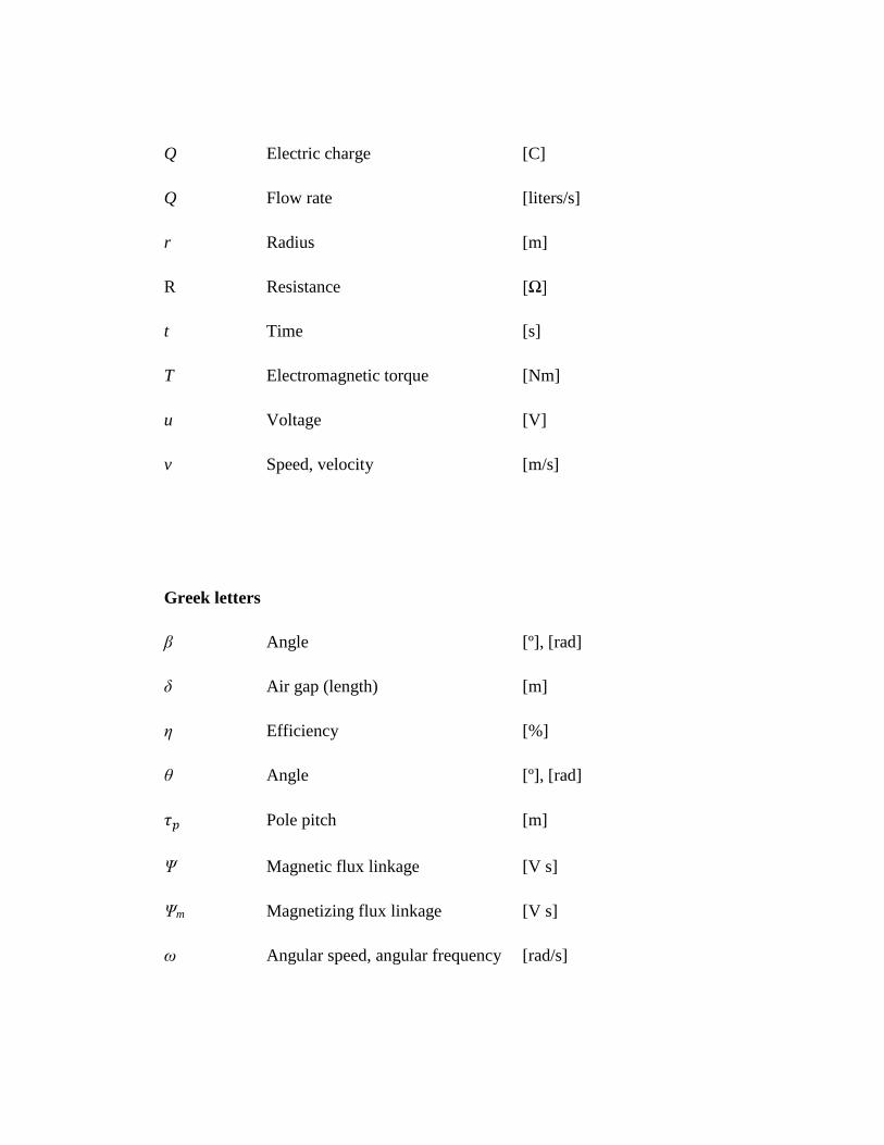
Q Electric charge [C]
Q Flow rate [liters/s]
r Radius [m]
R Resistance [Ω]
t Time [s]
T Electromagnetic torque [Nm]
u Voltage [V]
v Speed, velocity [m/s]
Greek letters
β Angle [º], [rad]
δ Air gap (length) [m]
η Efficiency [%]
θ Angle [º], [rad]
𝜏𝑝 Pole pitch [m]
Ψ Magnetic flux linkage [V s]
Ψm Magnetizing flux linkage [V s]
ω Angular speed, angular frequency [rad/s]

Subscripts
d, D Direct axis component
e Electromagnetic
m Magnetic
q, Q Quadrature axis component
r Rotor
s Stator
δ Air gap
Acronyms
AC Alternating Current
BEP Best Efficiency Point
DC Direct Current
EEI Energy Efficiency Index
EEM Energy-Efficient Motor
EPA Extended Product Approach
ErP Energy-related Products
EU European Union
FEM Finite Element Method
HEV Hybrid Electric Vehicle

IEC International Electrotechnical Commission
IM Induction Motor
IPMSM Interior Permanent Magnet Synchronous Motor
IRR Internal Rate of Return
LSPM Line Started Permanent Magnet motor
MEI Minimum Efficiency Index
NEMA National Electrical Manufacturers Association (United States)
OEM Original Equipment Manufacturer
PM Permanent Magnet
PMSM Permanent Magnet Synchronous Motor
PMASynRM Permanent Magnet-Assisted Synchronous Reluctance Motor
SynRM Synchronous Reluctance Motor
VSD Variable Speed Drive
9
Chapter 1
1 Introduction
1.1 Background
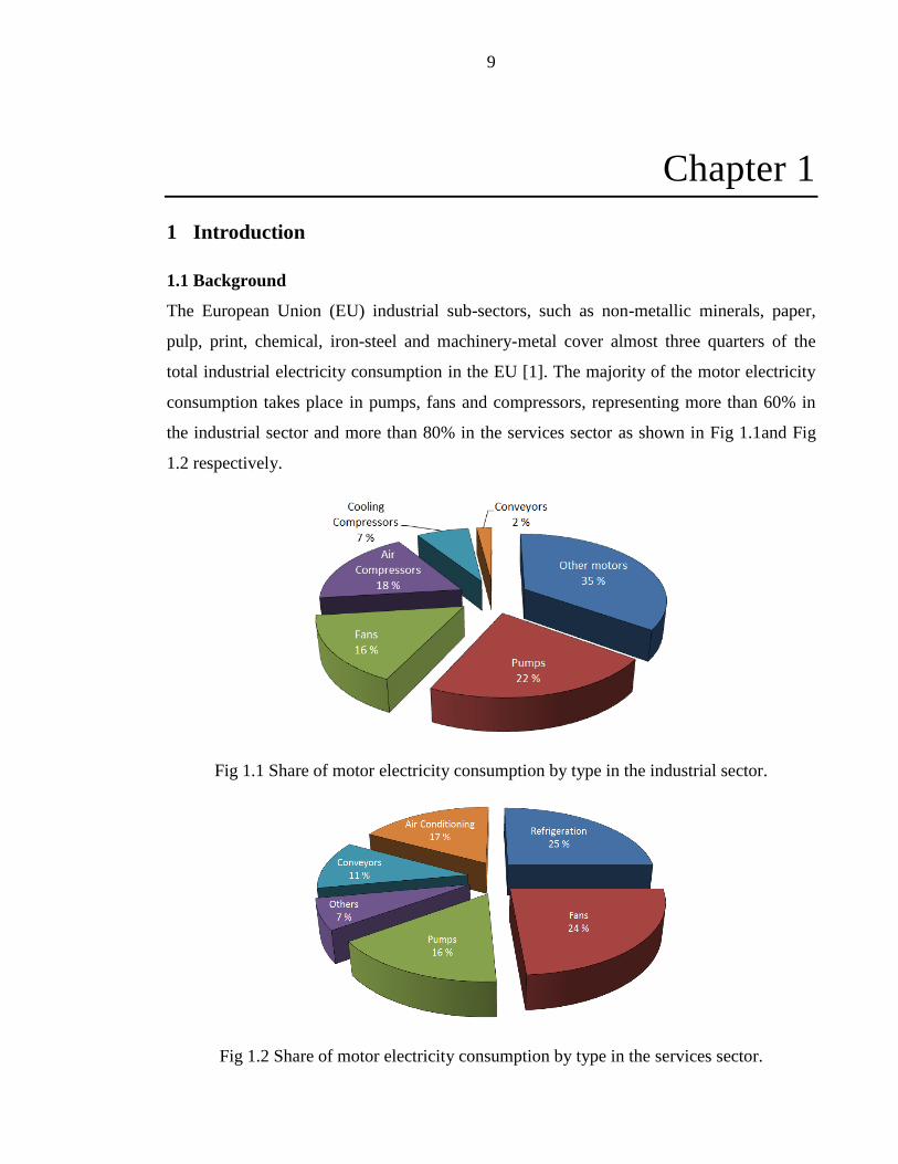
The European Union (EU) industrial sub-sectors, such as non-metallic minerals, paper,
pulp, print, chemical, iron-steel and machinery-metal cover almost three quarters of the
total industrial electricity consumption in the EU [1]. The majority of the motor electricity
consumption takes place in pumps, fans and compressors, representing more than 60% in
the industrial sector and more than 80% in the services sector as shown in Fig 1.1and Fig
1.2 respectively.
Fig 1.1 Share of motor electricity consumption by type in the industrial sector.
Fig 1.2 Share of motor electricity consumption by type in the services sector.
10
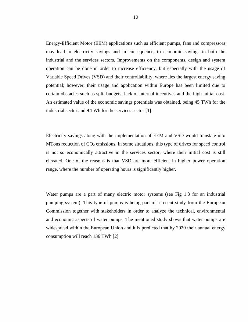
Energy-Efficient Motor (EEM) applications such as efficient pumps, fans and compressors
may lead to electricity savings and in consequence, to economic savings in both the
industrial and the services sectors. Improvements on the components, design and system
operation can be done in order to increase efficiency, but especially with the usage of
Variable Speed Drives (VSD) and their controllability, where lies the largest energy saving
potential; however, their usage and application within Europe has been limited due to
certain obstacles such as split budgets, lack of internal incentives and the high initial cost.
An estimated value of the economic savings potentials was obtained, being 45 TWh for the
industrial sector and 9 TWh for the services sector [1].
Electricity savings along with the implementation of EEM and VSD would translate into
MTons reduction of CO2 emissions. In some situations, this type of drives for speed control
is not so economically attractive in the services sector, where their initial cost is still
elevated. One of the reasons is that VSD are more efficient in higher power operation
range, where the number of operating hours is significantly higher.
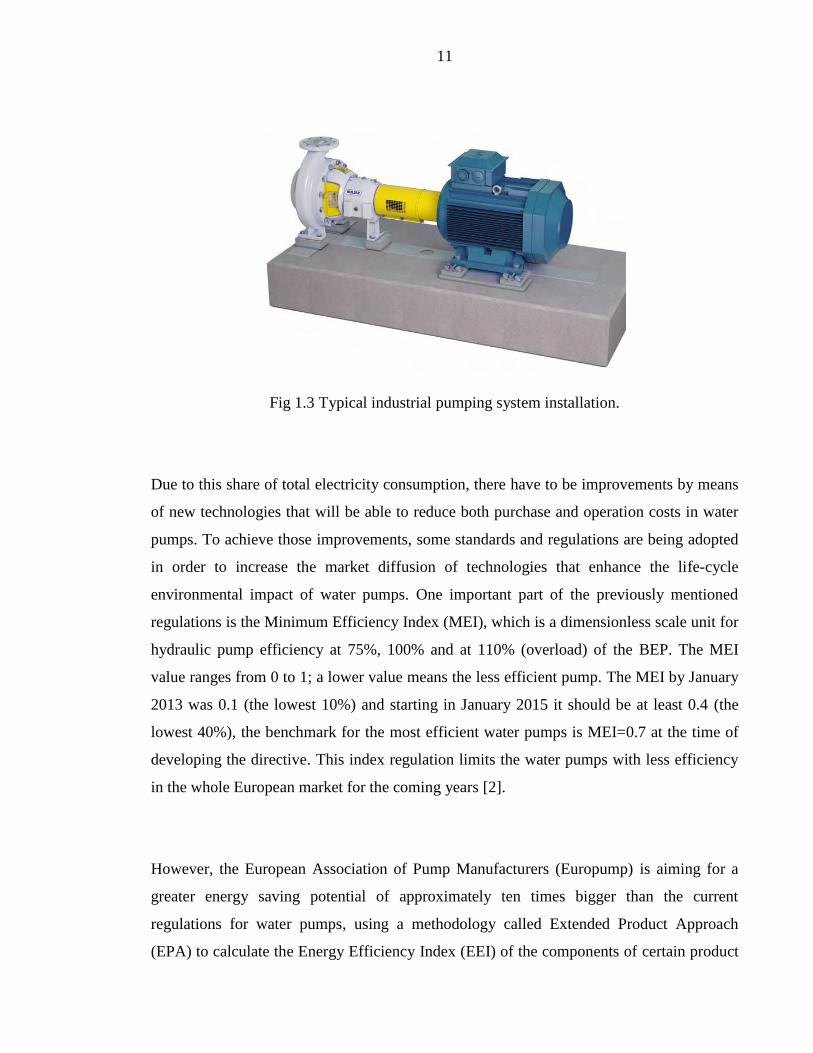
Water pumps are a part of many electric motor systems (see Fig 1.3 for an industrial
pumping system). This type of pumps is being part of a recent study from the European
Commission together with stakeholders in order to analyze the technical, environmental
and economic aspects of water pumps. The mentioned study shows that water pumps are
widespread within the European Union and it is predicted that by 2020 their annual energy
consumption will reach 136 TWh [2].
11
Fig 1.3 Typical industrial pumping system installation.
Due to this share of total electricity consumption, there have to be improvements by means
of new technologies that will be able to reduce both purchase and operation costs in water
pumps. To achieve those improvements, some standards and regulations are being adopted
in order to increase the market diffusion of technologies that enhance the life-cycle
environmental impact of water pumps. One important part of the previously mentioned
regulations is the Minimum Efficiency Index (MEI), which is a dimensionless scale unit for
hydraulic pump efficiency at 75%, 100% and at 110% (overload) of the BEP. The MEI
value ranges from 0 to 1; a lower value means the less efficient pump. The MEI by January
2013 was 0.1 (the lowest 10%) and starting in January 2015 it should be at least 0.4 (the
lowest 40%), the benchmark for the most efficient water pumps is MEI=0.7 at the time of
developing the directive. This index regulation limits the water pumps with less efficiency
in the whole European market for the coming years [2].
However, the European Association of Pump Manufacturers (Europump) is aiming for a
greater energy saving potential of approximately ten times bigger than the current
regulations for water pumps, using a methodology called Extended Product Approach
(EPA) to calculate the Energy Efficiency Index (EEI) of the components of certain product

12
(pump, motor or VSD) and also for integrated units. The EEI calculation of fixed speed
pumps and variable speed pumps will be evaluated according to reference control curves
and load profiles. Since EEI considers the applied flow control methods, it provides the
energy efficiency requirements and the expected future requirements for the whole system
that need to be adopted in the coming years [3].
One clear example of the so called ‘next generation’ pumping systems can be obtained
from circular pumps that must be controlled by a VSD and are now regulated by the EEI.
Such pumps can be built in small dimensions, for example the Grundfos MAGNA3, which
is constructed with a permanent magnet synchronous motor and integrated VSD (Fig 1.4).
Fig 1.4 MAGNA3 high-efficiency pump cutaway.
The MAGNA3 is an enhanced version of pumping systems with circulators and nowadays
is considered as a brand new concept for industrial pumping systems, it is being produced
by the Danish company Grundfos. It has a full range of high-efficiency circulators for
heating, cooling, ground source heat pump systems and domestic hot water applications.
The main features are corrosion protection, perfect insulation, clamp ring, Neodymium
technology rotor, compact stator, air cooling in control box, integrated sensors and high-
quality user interface [4].
13
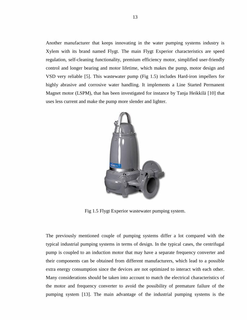
Another manufacturer that keeps innovating in the water pumping systems industry is
Xylem with its brand named Flygt. The main Flygt Experior characteristics are speed
regulation, self-cleaning functionality, premium efficiency motor, simplified user-friendly
control and longer bearing and motor lifetime, which makes the pump, motor design and
VSD very reliable [5]. This wastewater pump (Fig 1.5) includes Hard-iron impellers for
highly abrasive and corrosive water handling. It implements a Line Started Permanent
Magnet motor (LSPM), that has been investigated for instance by Tanja Heikkilä [10] that
uses less current and make the pump more slender and lighter.
Fig 1.5 Flygt Experior wastewater pumping system.
The previously mentioned couple of pumping systems differ a lot compared with the
typical industrial pumping systems in terms of design. In the typical cases, the centrifugal
pump is coupled to an induction motor that may have a separate frequency converter and
their components can be obtained from different manufacturers, which lead to a possible
extra energy consumption since the devices are not optimized to interact with each other.
Many considerations should be taken into account to match the electrical characteristics of
the motor and frequency converter to avoid the possibility of premature failure of the
pumping system [13]. The main advantage of the industrial pumping systems is the

14
capability of replacement of broken devices. At first instance, the pump and motor have
their own bearing construction and the frequency converter has to be manually configured
by the user.
1.2 Motivation for the study
One important part of any pumping system in terms of their construction is the motor type
that can be included, which may be chosen from different designs such as an Induction
Motor (IM), Synchronous Reluctance Motor (SynRM), Permanent Magnet Synchronous
Motor (PMSM) and Permanent Magnet-Assisted Synchronous Motor (PMASynRM). Their
main characteristics and construction will be analyzed in the next chapter together with the
equation model for these types of motors.
Some other criteria are also worth to mention, giving a high importance to the information
related to the costs that all of the different kind of pump configurations involve, their
maintenance and lifetime concerning both the customer and the manufacturer perspectives.
1.3 Objectives
To define the most energy efficient and versatile electric motor type for a 15 kW Close
Coupled Pump running at rated speed of 1500 rpm. The term versatility, in this case for an
electric motor, refers mainly to the dimensions that can be selected freely by the end-user
(height and principally the length), to the weight limitations regarding the motor
construction, and it also refers to the air ventilation that can be integrated in the machine.

15
To estimate the energy savings potential comparing different types of motors is also
considered as part of the objectives.
Figure 1.6 is an example, but not limited to a Close Coupled Pump to be analyzed [18],
which involves an impeller in the same shaft as the electric motor that drives the pump. The
pump itself does not have a separate coupling, saving money and time-consuming
operations. These characteristics among others, makes this type of pump simple and
available at a relatively low cost.
Fig 1.6 Close Coupled Pump.
An aluminum frame is ideal for motors in pumping applications and its inclusion has
increased over the past decades. Some advantages of this material are the dimensional
stability (to avoid warps and cracks), lighter weight (between 15% and 45%) translated into
lower costs, and improved heat dissipation, compared to a cast iron frame. New aluminum
alloys also bring high corrosion resistance and tensile strength [19].

16
Chapter 2
2 Motor comparisons and indicative results
2.1 Principles of electric motors
The force applied by the magnetic field on a charged object or a current-carrying conductor
can be calculated with the usage of the Lorentz force, which is considered as a force
experienced by an infinitesimal charge dQ moving at a speed v. The vector equation below
describes that force:
d𝐹 = d𝑄(𝐸 + 𝑣 × 𝐵) = d𝑄𝐸 +d𝑄
d𝑡d𝑙 × 𝐵 = d𝑄𝐸 + 𝑖d𝑙 × 𝐵 (2.1)
This basic vector equation is fundamental when computing the torque for electrical
machines, especially in the latter part of the equation, where a current-carrying element of a
conductor of length dl is considered [8].
Fig 2.1 Application of the magnetic part of the Lorentz force to a current-carrying
conductor.

17
Fig 2.1 shows the Lorentz force dF acting on a differential length dl of a conductor carrying
an electric current i in the magnetic field B. The angle β is measured between the conductor
and the flux density vector B. The vector product i dl x B may now be written in the form i
dl x B = i dlB sinβ. The force dF is perpendicular to the plane conformed by dl and B
according to the right-hand screw rule. The maximum value of dF is reached when dl and B
are perpendicular, in other words, sinβ = 1.
In an electrical machine, an air gap flux density Bδ that penetrates the rotor surface,
intersecting the current-carrying rotor bars, generates a tangential force on the periphery of
the rotor, as illustrated in the figure below:
Fig 2.2 Lorentz force acting on the rotor surface.
Fig 2.2 shows a current element of the width dx on a rotor surface. Also, the air gap flux
density Bδ is present acting upon that surface. The force dF’ and the rotor dimensions such
as radius and length are also illustrated.
Now we consider as sinusoidal both the flux density distribution and the linear current
density distribution and assume the magnetic flux direction perpendicular to the rotor

18
surface. Line integrating the Lorentz force dF around the surface of the rotor and
multiplying by the rotor radius, we obtain the electromagnetic torque equation, in this case,
for a two-pole machine [11]:
𝑇e = 𝑟 ∫ 𝐹2𝜋
0= 𝑟𝜏𝑝𝑐𝑜𝑠𝜃 (2.2)
where r is the rotor radius, A is the peak current density in the conductor, B the peak
magnetic flux density and 𝜏𝑝 the pole pitch. The electromagnetic torque can be shown in a
vector form if the equation 2.2 is analyzed with the usage of the space vector theory, which
is very useful for advanced control tasks. This results in the following general equation:
𝑇e =3
2𝑝(m × 𝑖s) (2.3)
where p is the number of poles, 𝑖s the stator current space vector and m the magnetic flux
linkage of the air gap. It has to be taken into account that both the flux linkage and the
current have to be always in the same voltage level and most of the time referred to the
stator winding.
2.2 Motor types under study and their construction
The main property of rotating electric machines is the transformation of mechanical energy
into electrical energy and vice versa. There are lots of industrial processes where the
electricity produced comes from these electrical machines; however, a relatively small
portion of electricity producing processes prescinds from the usage of rotating machines
and in that case, auxiliary motors are needed to fulfill the energy requirements [8].

19
Regarding the global electricity production, near half of it is being used in electric motors
and the demand of controlled drives applications is growing considerably, since the control
of torque must be accurate, those drives may save big amounts of energy.
There are two main categories of electric motors and they rely on the type of electric
system to which the motor is connected, one of them is the direct current (DC) motors and
the other is alternating current (AC) motors. One advantage of AC motors against DC is the
lower maintenance requirement. Motors with alternating current supply are divided in two
subcategories: synchronous and asynchronous motors. The speed of the rotor matches the
speed of the magnetic field in the case of a synchronous machine, while the speed does not
coincide in the case of an induction machine [7]. A figure of the basic construction of an
AC motor is shown next, describing the main parts that conforms the machine (Fig 2.3).
Fig 2.3 AC motor basic construction
Now an in-depth image shows the stator construction, which is made up of many thin
laminations of cast iron or aluminum. They are perforated and clamped together to form the

20
stator core in shape of a hollow cylinder with slots. Coils of insulated wires are inserted
into these slots and each group of coils forms a pair of poles. The number of poles depends
on the internal connection of the stator windings. A three-phase winding is placed and
arranged in the stator core slots to create a rotating magnetic field (Fig 2.4).
Fig 2.4 Detailed stator construction of an induction machine.
1. Stator core 2. Steel laminations 3.Winding 4. Slots
Transient states are present in electrical machines in the start-up and through some parts of
the process control, either fed by a frequency converter or by a sinusoidal supply. There are
equivalent circuits for motors in both the stationary and the transient state, but the last one
needs to be analyzed with the help of different techniques, one of them is the Space Vector
Theory, where the next assumptions are made with the aim of simplify the analysis:
- Flux density distribution in the air gap is considered as sinusoidal.
- Saturation of the magnetizing circuit is assumed constant.
- Iron losses are neglected.
- Inductances and resistances are independent of the frequency and temperature.

21
As an example, the equivalent circuit of an induction motor is shown in Fig 2.5. It has a
reference frame rotating at speed ωg. The voltages u and currents i are vectors, the flux
linkages 𝜓 are also vectors. The angular frequency ωg is not present in the stator reference
frame [11].
Fig 2.5 Equivalent circuit of an induction motor based on Space Vector Theory.
From now on, the voltages and flux linkages can be represented with the following
equations. At first instance, the voltage equations 2.4 and 2.5 must be set in a general frame
of reference and rotating at an angular speed 𝜔g. The additional motion voltage term
𝑗𝜔g𝜓s/r is applied to these equations whenever the observation frame of reference rotates.
𝑢s = 𝑅s𝑖s +d𝜓s
d𝑡+ 𝑗𝜔g𝜓s (2.4)
𝑢r = 𝑅r𝑖r +d𝜓r
d𝑡+ 𝑗(𝜔g − 𝑝Ω)𝜓r (2.5)
where pΩ is the rotor electrical angular speed, also indicated as ωg. The flux linkages
occurring in equations 2.4 and 2.5 are represented in the equations below:

22
𝜓s = 𝐿s𝑖s + 𝐿m𝑖r (2.6)
𝜓r = 𝐿r𝑖r + 𝐿m𝑖s (2.7)
where 𝐿m is the magnetizing inductance, 𝐿s is the total inductance of the stator (calculated
as 𝐿m + 𝐿sσ) and 𝐿r is the total inductance of the rotor (𝐿m + 𝐿rσ). 𝐿sσ and 𝐿rσ are
the leakage inductances of the stator and rotor, respectively. The magnetizing flux linkage
is thus a product of the varying inductance and the current [11]:
𝜓m = 𝐿m(𝑖s + 𝑖r) = 𝐿m𝑖m (2.8)
In the coming sections of this chapter, four different types of AC motors are being studied
(IM, PMSM, SynRM and PMASynRM) by meanings of their construction (weight and
components), efficiency and equation models. Besides this, a comparison is done including
different applications where these types of motors appear.
2.2.1 Induction Motor
Induction motors have been present in the industrial sector for several years and still are the
preferred and most used electric machine type due to its simple construction that brings
high reliability, their robustness and also to the low manufacturing and maintenance costs
[9]. There are two types of induction motors: single-phase and three-phase. The first one is
fed by single-phase power supply and its pulsating magnetic field is produced by the stator
winding. Household applications are the most common usage for this type of induction
motor, such as refrigerators, fans, washing machines, coolers, etc.
On the other hand, the three-phase induction motor is fed by three-phase power supply and
the present rotating magnetic field is produced by the stator windings. Their application
focuses in industrial drives like pumps, drills, stamping presses, metal cutting machine

23
tools, conveyors, etc. At the same time, three-phase induction motors are divided in two
different kinds: squirrel cage rotor and wound rotor [7].
In terms of construction (Fig 2.6), the stator is the fixed part of the motor, which is a hollow
laminated cylinder, also called a stator core, with axial slots on its inner surface. Said core
is made of steel laminations, insulated each one from another. The rotor is the rotating part
of the motor and is settled inside the stator. The rotor is a laminated cylinder (rotor core)
with axial slots on its outside surface, winding and the shaft. It is also built with insulated
steel laminations. An air gap is present between the stator and the rotor.
Motor bearings are also an important part of the construction of a machine because they
provide a reduction of the rotational friction and support for both radial and axis loads.
There are different types of motor bearings depending on the application and their selection
must be carefully taken into account. The most common type is the deep groove ball
bearing, suitable for high speeds due to their low frictional torque. Cylindrical roller
bearings, sleeve bearings and angular contact ball bearings are other types among the
available variety on the market nowadays [14].

24
Fig 2.6 Induction motor construction overview.
As already mentioned before, the construction of the stator is practically the same in all AC
motor types; however, the difference resides on the rotor composition where we can find
two types as seen previously: squirrel cage rotor and wound rotor (also known as slip-ring
rotor). The first one possesses bars short-circuited at each end by two rings (Fig 2.7).
Fig 2.7 Detailed squirrel cage rotor construction and winding.
1. Rotor core 2. Bars 3. End rings 4. Shaft

25
When there are two squirrel cages, one inside the other, both windings are independent and
this kind of rotor is known as double cage (Fig 2.8). This type of rotors is rarely used in the
industry; their main application is for producing NEMA C characteristics, which require a
high starting torque with low starting current. They are more expensive than class A and B
designs that are meant to have a normal starting torque and current. Double cage rotors are
used for high starting torque loads, such as loaded pumps, compressors and conveyors [15].
Fig 2.8 Detailed double squirrel cage rotor construction and winding.
1. Rotor core 2. Bars 3. End rings 4. Shaft
In the case of a wound rotor, the winding is made of coils; each one consists of several
insulated wire turns. When connected in series, these coils form a coil group. In the
simplest form, a three-phase winding has three coil groups and each group has up to one
coil. Hence, the three identical coils have a 120 electrical degrees phase shift. Wound rotor
has a complicated design that in consequence increases the costs and decreases the
reliability. That is why this type of rotor will not be analyzed further in this paper.
Nowadays it is used just in a few applications that require heavy starting duty and also in
some drivers that need speed control [7].
26
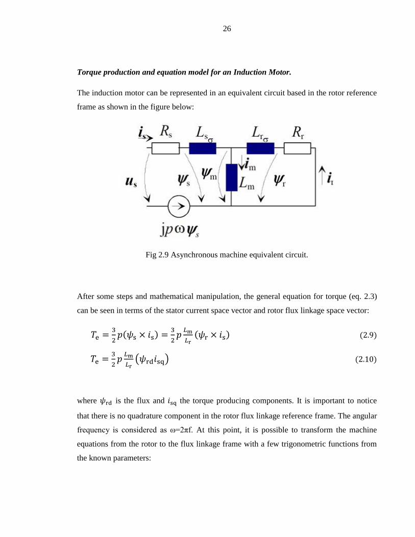
Torque production and equation model for an Induction Motor.
The induction motor can be represented in an equivalent circuit based in the rotor reference
frame as shown in the figure below:
Fig 2.9 Asynchronous machine equivalent circuit.
After some steps and mathematical manipulation, the general equation for torque (eq. 2.3)
can be seen in terms of the stator current space vector and rotor flux linkage space vector:
𝑇e =3
2𝑝(𝜓s × 𝑖s) =
3
2𝑝
𝐿m
𝐿r(𝜓r × 𝑖s) (2.9)
𝑇e =3
2𝑝
𝐿m
𝐿r(𝜓rd𝑖sq) (2.10)
where 𝜓rd is the flux and 𝑖sq the torque producing components. It is important to notice
that there is no quadrature component in the rotor flux linkage reference frame. The angular
frequency is considered as ω=2πf. At this point, it is possible to transform the machine
equations from the rotor to the flux linkage frame with a few trigonometric functions from
the known parameters:
27
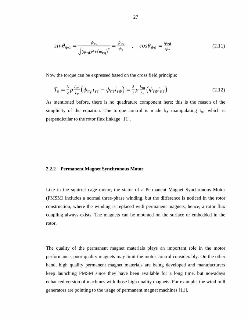
𝑠𝑖𝑛𝜃𝜓d =𝜓rq
√(𝜓rd)2+(𝜓rq)2
=𝜓rq
𝜓r , 𝑐𝑜𝑠𝜃𝜓d =
𝜓rd
𝜓r (2.11)
Now the torque can be expressed based on the cross field principle:
𝑇e =3
2𝑝
𝐿m
𝐿r(𝜓r𝜓𝑖sT − 𝜓rT𝑖s𝜓) =
3
2𝑝
𝐿m
𝐿r(𝜓r𝜓𝑖sT) (2.12)
As mentioned before, there is no quadrature component here; this is the reason of the
simplicity of the equation. The torque control is made by manipulating 𝑖sT which is
perpendicular to the rotor flux linkage [11].
2.2.2 Permanent Magnet Synchronous Motor
Like in the squirrel cage motor, the stator of a Permanent Magnet Synchronous Motor
(PMSM) includes a normal three-phase winding, but the difference is noticed in the rotor
construction, where the winding is replaced with permanent magnets, hence, a rotor flux
coupling always exists. The magnets can be mounted on the surface or embedded in the
rotor.
The quality of the permanent magnet materials plays an important role in the motor
performance; poor quality magnets may limit the motor control considerably. On the other
hand, high quality permanent magnet materials are being developed and manufacturers
keep launching PMSM since they have been available for a long time, but nowadays
enhanced version of machines with those high quality magnets. For example, the wind mill
generators are pointing to the usage of permanent magnet machines [11].

28
In terms of the physical construction, the rotor of a permanent magnet machine can be built
of electric sheet, like the case of an asynchronous motor and of course different types of
lamination exist with the aim of giving the desired characteristics of the machine. The
stator of a permanent magnet machine is quite similar to the one of an induction machine.
Fig 2.10 shows the cutaway diagram of the permanent magnet synchronous machine. More
details about the rotor construction can be seen later in this section.
Fig 2.10 Permanent Magnet Synchronous Motor construction overview.
The usage of magnets in the machine, either embedded or surface mounted in the rotor,
provides unique characteristics since the permanent magnet material is indeed part of the
magnetic circuit of the machine, which leads to an impact or influence on the reluctance.
Control methods in PMSM vary depending on the position of the permanent magnets in the
rotor and they require information on the rotor angle. The magnets can be located in a
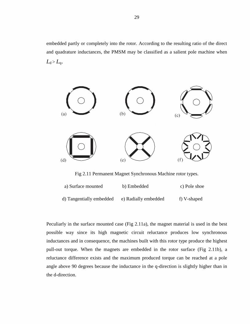
different array in the rotor as shown in Fig 2.11. They can be glued on the rotor surface or
29
embedded partly or completely into the rotor. According to the resulting ratio of the direct
and quadrature inductances, the PMSM may be classified as a salient pole machine when
Ld > Lq.
Fig 2.11 Permanent Magnet Synchronous Machine rotor types.
a) Surface mounted b) Embedded c) Pole shoe
d) Tangentially embedded e) Radially embedded f) V-shaped
Peculiarly in the surface mounted case (Fig 2.11a), the magnet material is used in the best
possible way since its high magnetic circuit reluctance produces low synchronous
inductances and in consequence, the machines built with this rotor type produce the highest
pull-out torque. When the magnets are embedded in the rotor surface (Fig 2.11b), a
reluctance difference exists and the maximum produced torque can be reached at a pole
angle above 90 degrees because the inductance in the q-direction is slightly higher than in
the d-direction.

30
In Fig 2.11c the rotor plates shape resembles the construction of a salient-pole machine
where a sinusoidal flux density is achieved in the air gap and a smooth and quiet operation
is achieved at a low rotation speed. In addition, the poles are designed to obtain a sinusoidal
form in the flux and at the same time to reduce the magnetic leakage on the machine. The
rotor of the machines from Fig 2.11d and e gives the motor a hybrid property because it
behaves somehow as a SynRM without magnets. The torque is produced by the different
inductances in both the direct and quadrature directions. In fact, the resulting torque is
known as reluctance torque. Adding the magnets to this hybrid machine results in
improvements at start-up, also the efficiency and power factor are considerably better than
in the SynRM.
In the case of V-shaped magnets (Fig 2.11f), two magnets are used per pole and it is
possible to get a high air gap flux density in no-load conditions. The number of pole pairs is
usually high because the thickness of the stator yoke (meaning the stator surface) is reduced
and therefore a larger rotor diameter exists in the machine [8].
Torque production and equation model for a Permanent Magnet Synchronous Motor.
The equivalent circuits of a PMSM are obtained analyzing the machine with direct and
quadrature reference frame fixed to the rotor. Those circuits can be seen in Fig 2.12.
31
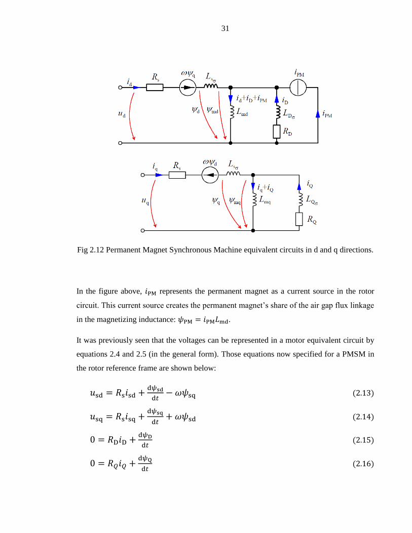
Fig 2.12 Permanent Magnet Synchronous Machine equivalent circuits in d and q directions.
In the figure above, 𝑖PM represents the permanent magnet as a current source in the rotor
circuit. This current source creates the permanent magnet’s share of the air gap flux linkage
in the magnetizing inductance: 𝜓PM = 𝑖PM𝐿md.
It was previously seen that the voltages can be represented in a motor equivalent circuit by
equations 2.4 and 2.5 (in the general form). Those equations now specified for a PMSM in
the rotor reference frame are shown below:
𝑢sd = 𝑅s𝑖sd +d𝜓sd
d𝑡− 𝜔𝜓sq (2.13)
𝑢sq = 𝑅s𝑖sq +d𝜓sq
d𝑡+ 𝜔𝜓sd (2.14)
0 = 𝑅D𝑖D +d𝜓D
d𝑡 (2.15)
0 = 𝑅𝑄𝑖𝑄 +d𝜓Q
d𝑡 (2.16)

32
The flux linkage components can be obtained with the coming equations:
𝜓sd = 𝐿sd𝑖sd + 𝐿md𝑖D + 𝜓PM (2.17)
𝜓sq = 𝐿sq𝑖sq + 𝐿mq𝑖𝑄 (2.18)
𝜓D = 𝐿md𝑖sd + 𝐿D𝑖D + 𝜓PM (2.19)
𝜓Q = 𝐿mq𝑖sq + 𝐿Q𝑖Q (2.20)
The field current generates a flux linkage in the permanent magnet:
𝑖PM =𝜓PM
𝐿md (2.21)
Nevertheless, the field current 𝑖PM is not constant; this is due to the saturation of the
magnetizing inductance 𝐿md which produces the permanent magnet’s share of the air gap
flux linkage.
Using the cross-field principle, the torque equation can be obtained. Torque is a starting
point for the development of many control principles of a PMSM:
𝑇e =3
2𝑝[𝜓PM𝑖sq − (𝐿mq − 𝐿md)𝑖sd𝑖sq + 𝐿md𝑖D𝑖sq + 𝐿mq𝑖Q𝑖sd] (2.22)
The first term 𝜓PM𝑖sq depends on the flux linkage of the permanent magnets and on the
stator current perpendicular to the flux linkage. The second term (𝐿mq − 𝐿md)𝑖sd𝑖sq could
be of high importance if the saliency ratio in the d and q axes is large. The third and fourth
terms are related to the torque components of the damper windings, they only occur during
transients [11].

33
2.2.3 Synchronous Reluctance Motor
Along with the permanent magnet motor, the Synchronous Reluctance Motor (SynRM) has
been gaining a place in the market. One of the main reasons is the convenient properties
they offer, and another reason is that the developing of an induction machine cannot go any
further, despite of being the most inexpensive industrial motor type.
The SynRM is also a three-phase electric motor with the attribute of having the rotor
construction in a peculiar way, where the measured values vary depending on the direction.
Electric steel plates are stacked together forming the rotor structure. Those plates have
punched holes that act as flux barriers.
The torque produced in a SynRM is proportional to the difference between the d and q axes
inductances, bigger difference means more torque production. The direct axis is built with
magnetically conductive material (iron in the majority of cases) and the quadrature axis is
designed with magnetically insulating material (air) [11]. Fig 2.13 shows an example of the
construction for the reluctance machine.

34
Fig 2.13 Synchronous Reluctance Motor construction overview.
The aim of the construction of the rotor in a SynRM is to keep the saliency ratio as large as
possible. This ratio takes into account the direct axis inductance 𝐿d and the quadrature axis
inductance 𝐿q. The saliency ratio mainly determines the peak torque of the machine, power
factor and the maximum possible efficiency. If we compare a SynRM with an IM of the
same size, the saliency ratio of the synchronous reluctance motor should be at least ten to
make it competitive against the induction motor.
The rotor of a synchronous reluctance machine has many different types of construction
and in hence, the saliency ratio varies from one to another. These rotor types are shown in
Fig 2.14 and explained briefly afterwards.
35
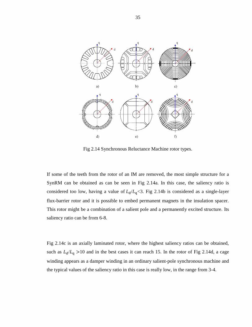
Fig 2.14 Synchronous Reluctance Machine rotor types.
If some of the teeth from the rotor of an IM are removed, the most simple structure for a
SynRM can be obtained as can be seen in Fig 2.14a. In this case, the saliency ratio is
considered too low, having a value of 𝐿d/𝐿q<3. Fig 2.14b is considered as a single-layer
flux-barrier rotor and it is possible to embed permanent magnets in the insulation spacer.
This rotor might be a combination of a salient pole and a permanently excited structure. Its
saliency ratio can be from 6-8.
Fig 2.14c is an axially laminated rotor, where the highest saliency ratios can be obtained,
such as 𝐿d/𝐿q >10 and in the best cases it can reach 15. In the rotor of Fig 2.14d, a cage
winding appears as a damper winding in an ordinary salient-pole synchronous machine and
the typical values of the saliency ratio in this case is really low, in the range from 3-4.

36
Another rotor type that may have mounted permanent magnets, if desired, is the one in Fig
2.14e, which is also a single-layer flux-barrier kind. The aim of including the magnets here
is to avoid the passing of the flux in the quadrature axis direction. Fig 2.14f represents a
multi-layer flux-barrier rotor construction where the quadrature axis reluctance is reduced
because of the supports in the round laminates. The maximum possible saliency ratio is 10,
in other words, 𝐿d/𝐿q <10. This rotor type seems to be currently used for commercial
versions of SynRMs [11].
Torque production and equation model for a Synchronous Reluctance Motor.
Similarly as the PMSM, the machine characteristics of a SynRM are different in the d and q
axes due to the rotor structure; otherwise, the equivalent circuit resembles the one of the
IM. In the same manner, there are equivalent circuits analyzing the machine with direct and
quadrature reference frame fixed to the rotor:
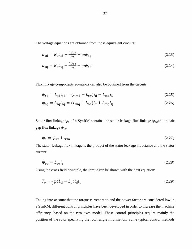
Fig 2.15 Synchronous Reluctance Machine equivalent circuits in d and q directions.
37
The voltage equations are obtained from those equivalent circuits:
𝑢sd = 𝑅s𝑖sd +𝑑𝜓sd
𝑑𝑡− 𝜔𝜓sq (2.23)
𝑢sq = 𝑅s𝑖sq +𝑑𝜓sq
𝑑𝑡+ 𝜔𝜓sd (2.24)
Flux linkage components equations can also be obtained from the circuits:
𝜓sd = 𝐿sd𝑖sd = (𝐿md + 𝐿sσ)𝑖d + 𝐿md𝑖D (2.25)
𝜓sq = 𝐿sq𝑖sq = (𝐿mq + 𝐿sσ)𝑖𝑞 + 𝐿mq𝑖Q (2.26)
Stator flux linkage 𝜓s of a SynRM contains the stator leakage flux linkage 𝜓sσand the air
gap flux linkage 𝜓m:
𝜓s = 𝜓sσ + 𝜓m (2.27)
The stator leakage flux linkage is the product of the stator leakage inductance and the stator
current:
𝜓sσ = 𝐿sσ𝑖s (2.28)
Using the cross field principle, the torque can be shown with the next equation:
𝑇e =3
2𝑝(𝐿d − 𝐿q)𝑖d𝑖q (2.29)
Taking into account that the torque-current ratio and the power factor are considered low in
a SynRM, different control principles have been developed in order to increase the machine
efficiency, based on the two axes model. These control principles require mainly the
position of the rotor specifying the rotor angle information. Some typical control methods
38
are the Current Vector Control, Constant Stator Current Control, Direct Torque Control
[17] and Flux Linkage Control, among others [11].
2.2.4 Permanent Magnet-Assisted Synchronous Reluctance Motor
The implementation of permanent magnets is helping the development of synchronous
motors with higher efficiency that also reduces power consumption and in consequence,
contributes in a certain manner to a global environmental preservation. So far both the
PMSM and SynRM have been analyzed and in brief, the first machine type uses a powerful
magnetic field flux and the second one uses the reluctance generated by the rotor
electromagnetic saliency. SynRM is considered as a low-cost with high efficiency and one
of the considerations for this is the fact that it does not have secondary copper losses in the
rotor.
Some tests and comparisons have been done in terms of efficiency and the economical
point of view between a PMSM with embedded magnets in the rotor (also known as
Interior Permanent Magnet Synchronous Motor, IPMSM), a SynRM and an IM, in the
same conditions. After the evaluation, the highest efficiency was found in the IPMSM with
a value of over 95% but it was not economical due to the costs of the permanent magnets’
material. The SynRM gave better results than the IM in both the efficiency and costs [16].
Taking those results into account, the concept of an optimal design that could have a great
efficiency at a low cost (meaning a small quantity of magnets) was originated and
conceived as a Permanent Magnet-Assisted Synchronous Reluctance Motor (PMASynRM,
Fig 2.16) that, compared to a PMSM, can give the same efficiency using only one-fourth
the amount of magnets.

39
Fig 2.16 PMASynRM rotor construction overview using FEM (left) and a real prototype
(right).
Some rotor structures of this so called PMASynRM are shown in Fig 2.17 where (a) and (c)
are mostly used for hybrid electric vehicle (HEV) or similar applications. (b), (e) and (f) are
examples of the complexity on designs where the insulation layers are really close to the
shape of the natural flux lines inside the solid rotor. (d) is a clearer example of the
implementation of high quality PM materials such as neodymium (NdFeB) minimizing the
volume of the magnet [20].

40
Fig 2.17 Permanent Magnet-Assisted Synchronous Reluctance Machine rotor types.
Torque production and equation model for a Permanent Magnet-Assisted Synchronous
Reluctance Motor.
Previously it has been mentioned that the saliency ratio plays an important role in the
performance of any SynRM, now considering the addition of the magnets in the rotor, the
produced torque will increase whenever the same amount of current is applied, doing it so,
the phase voltage should be higher [21].
To obtain the voltage and flux linkage equations, the direct and quadrature axes are the
reference frame again and assuming appropriate conditions, the results are the same as
equations 2.13 and 2.14 for voltages, equations 2.17 and 2.18 for the flux linkages, all
resembling the behavior of the PMSM [22].

41
The torque equation for the PMASynRM parts from the SynRM (equation 2.29), but the
addition of the magnets to the rotor creates a flux linkage that should be included for further
analysis [21]:
𝑇e =3
2𝑝[(𝐿d − 𝐿q)𝑖d𝑖q + 𝜓PM𝑖sd] (2.30)
As the name implies, a PMASynRM is a combination of both the synchronous reluctance
and the permanent magnet synchronous machines. That fact can be proven with the
equations shown so far. The addition of permanent magnets causes an increment in the
saliency ratio and in consequence, their difference also increases, leading to the obtainment
of a higher power factor and a higher torque [21].
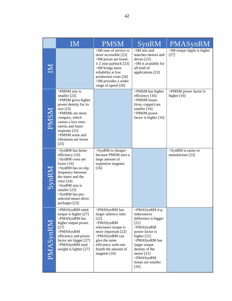
2.3 Comparison including different applications
This section summarizes the arguments for and against within the four types of motors
analyzed so far. Different applications have been taken into account to make this
comparison and the results are shown in Table 2.1.
Table 2.1 Motor comparison considering different applications.
42
IM PMSM SynRM PMASynRM IM
>IM ease of service is
more accessible [23]
>IM prices are lower:
1-2 year payback [23]
>IM brings more
reliability at low
production costs [26]
>IM provides a wider
range of speed [26]
>IM mix and
matches motors and
drives [23]
>IM is available for
all kind of
applications [23]
>IM torque ripple is higher
[27] P
MS
M
>PMSM size is
smaller [23]
>PMSM gives higher
power density for its
size [25]
>PMSMs are more
compact, which
causes a low rotor
inertia and faster
response [25]
>PMSM noise and
vibrations are lower
[25]
>PMSM has higher
efficiency [16]
>PMSM losses
(iron, copper) are
smaller [16]
>PMSM power
factor is higher [16]
>PMSM power factor is
higher [16]
SynR
M
>SynRM has better
efficiency [16]
>SynRM costs are
lower [16]
>SynRM has no slip
frequency between
the stator and the
rotor [24]
>SynRM size is
smaller [23]
>SynRM has pre-
selected motor-drive
packages [23]
>SynRM is cheaper
because PMSM uses a
large amount of
expensive magnets
[16]
>SynRM is easier to
manufacture [23]
PM
AS
yn
RM
>PMASynRM rated
torque is higher [27]
>PMASynRM has
higher output power
[27]
>PMASynRM
efficiency and power
factor are bigger [27]
>PMASynRM total
weight is lighter [27]
>PMASynRM has
larger saliency ratio
[22]
>PMASynRM
reluctance torque is
more important [22]
>PMASynRM can
give the same
efficiency with one-
fourth the amount of
magnets [16]
>PMASynRM d-q
inductances
difference is bigger
[21]
>PMASynRM
power factor is
higher [21]
>PMASynRM has
larger torque
density of the
motor [21]
>PMASynRM
losses are smaller
[16]

43
The numbers inside brackets correspond to the reference of the documents at the bottom of
this paper. In the list below, the content of each reference is named according to its
application.
[16] Performance evaluation made out of four different rotor types.
[21] Effects of rotor structure on torque by means of Finite Element Method (FEM).
[22] Air-conditioner compressor.
[23] Innovative motor and drive package.
[24] Online parameter identification for sensorless control.
[25] Cooling towers.
[26] Hybrid electrical vehicles.
[27] Electric motor for existing vessels and future ships and submarines.
2.4 High efficiency pump motors
The International Electrotechnical Commission (IEC) published the standard IEC 60034-
30-1 in March 2014 related to the energy efficiency classes for electric motors, covering a
wide range that goes from 0.12 kW to 1000 kW, single and three phase motors, both 50 and
60 Hz frequencies and the number of poles 2, 4, 6 or 8. It is important to notice that this
standard does not cover motors completely integrated into a machine [28].

44
The efficiency classes defined by IEC 60034-30-1 are:
- IE1 Standard efficiency
- IE2 High efficiency
- IE3 Premium efficiency
- IE4 Super-Premium efficiency
An example of the classification can be seen in Fig 2.18 that shows different output values
and their minimum efficiencies.
Fig 2.18 IE efficiency classes for 4 pole motors at 50 Hz
Apart from these four classes, a new level named IE5 is expected to emerge in future
revisions. The aim of IE5 will be to reduce losses by 20% compared to the IE4 class [28].
Since January 2015, motors from 7.5 kW to 375 kW must reach the IE3 efficiency level, or
at least they should include a VSD to meet the requirements imposed by the IEC. By
January 2017 these regulations will be extended down to motors of 0.75 kW [29].

45
ABB introduced a magnet free IE4 SynRM back in 2011, it was a big achievement because
this efficiency level was established three years later. Demands for increasing the efficiency
force an Original Equipment Manufacturer (OEM) to find new solutions in order to reduce
the energy consumption and ABB is no exception, as a reply for this demand, the company
is introducing the new SynRM2 technology which claims to reduce motor losses by 20%,
achieving the IE5 Ultra-Premium efficiency [30].
The SynRM2 technology platform (Fig 2.19) contains ferrite magnets, which are especially
more cost effective and also easier to source than the rare earth magnets. As a result, the
motor is more sustainable in both aspects economic and ecological. The mentioned
technology is quite flexible since it is optimized to meet the technical and commercial
characteristics according to the customer requirements.
Fig 2.19 SynRM2 technology concept.
Another example of high efficiency pump motors is the speed-controlled KSB SuPremE
(Fig 2.20) with a wide variety of applications. This SynRM already meets the IE4

46
efficiency requirements and even exceeds the regulations of the European ErP (Energy
related Products) for 2017. It is built without magnetic materials and in hence the total
environmental footprint is smaller than in the case of PMSMs. The rating power can be
from 0.55 to 45 kW [31].
Fig 2.20 KSB SuPremE high efficiency SynRM.

47
Chapter 3
3 Evaluation of 15 kW motors
3.1 Motor characteristics comparison
From this stage of the study, we will be focusing in the 15 kW motors to evaluate, at first
instance, an induction motor and a SynRM since they are in the facilities of the LUT
laboratories, allowing us to run certain tests to obtain some electrical parameters and the
most important part of this paper: efficiency results, from where we can trace and create
graphics and also efficiency maps. Afterwards, some other comparisons will be made
including results from simulations of a PMSM using Finite Element Methods (FEM) to
extend the motor efficiency comparison study.
In the first place, the motor nameplates from the IM and SynRM located in the LUT
laboratories will be shown and explained in Fig 3.1, according to their respective product
codes to have an overview of the characteristics of both motors.
Fig 3.1 Nameplates explanation for the IM and SynRM in LUT laboratories.

48
Secondly, the similarities between the two mentioned types of motors, in terms of
construction, dimensions and other characteristics will be shown in Table 3.1.
Table 3.1 Dimensions and other characteristics for the IM and SynRM in LUT laboratories.
IM (3-phase) SynRM (3-phase)
Mounting IM1001, B3 (foot) IM1001, B3 (foot)
Type of duty S1(IEC) 100% S1(IEC) 100%
Nominal torque TN 97Nm 95Nm
Insulation class / Temp. class
F / B F / B
Ambient temperature 40°C 40°C
Altitude 1000 m.a.s.l. 1000 m.a.s.l.
Enclosure IP55 IP55
Cooling system IC411 self-ventilated IC411 self-ventilated
Bearing DE/NDE 6309/C3 - 6209/C3 63092Z/C3 - 62092Z/C3
Position of terminal box Top Top
Total weight of motor 187Kg 177Kg
Number of poles 4 4
Product IE Class IE3 IE4
Frame material Cast Iron Cast Iron
Length 681mm 671.5mm
Width 338mm 338mm
Height 421mm 421mm
Price (VAT 0%) 1 810 € 2 014 €
ACS850 Price (VAT 0%) 1 050 €
The type of mounting is the same for both motors (IM1001 B3), it is foot-mounted with the
terminal box on top, the type of duty is also the same (S1), considered as a continuous duty
where the motor keeps working at a constant load long enough to reach the temperature
equilibrium, the nominal torque varies only for 2Nm, the insulation class F and temperature
class B mean in brief that the safety margin goes up to 25°C, both motors may work at a
maximum ambient temperature of 40°C and at an altitude of 1000 meters above sea level.

49
The type of enclosure is the same (IP55) and means that it is dust-protected and also with
protection against water jets, the same cooling system is used in both motors (IC411) so
that the frame surface uses a primary and a secondary coolant with self-circulation. The
type of bearings is also the same used in both motors, named as “deep groove ball
bearings”, but for the SynRM they are shielded to prevent incoming dirt, that is defined by
the 2Z ending in the bearing part number.
The total weight of the motor is quite similar, just about 5% heavier in case of the IM.
About the physical dimensions they only vary by the length a bit, being the SynRM larger
than the IM.
There are other characteristics where we can compare the motor types, but it will lead to an
extensive study which cannot be covered on this thesis. For example, the type of bearings
has a slight difference as it was just mentioned and along with other components or
materials, there may be small mechanical losses to consider for comparison. That is why we
are focusing on the most relevant characteristics of the motors.
3.2 Motor efficiency comparison
Several tests were performed inside the LUT laboratories (Fig 3.2), setting parameters such
as speed, frequency, current, voltage, references according to nominal values, etc. that led
to the obtainment of efficiency measurements and other results for both the induction motor
and the SynRM when driven by a VSD. It is important to mention that those tests took
place while using constant flux.

50
Fig 3.2 Motor settings for test in LUT laboratories.
As a result, we were able to compare also the efficiency measurements against the
manufacturer’s declaration in the motor data sheet, considering six different speeds, starting
with 750 rpm and finalizing with the nominal speed value of 1500 rpm. There was also the
need of interpolate the data to construct new points for each curve within the range of the
already known data points as seen in Fig 3.3 in order to obtain the efficiency curves.

51
Fig 3.3 IM and SynRM efficiency comparison.
We can see from the figure above that the efficiency curve declared by the manufacturer in
the case of the SynRM (dark blue) looks quite similar to the curve of the motor
measurements inside the laboratory (red), it is even showing a higher efficiency percentage
at 1500 rpm in the red curve, reaching 91.73% compared to the stated 91.3% from the
manufacturer, meaning that the tests were successful and accurate considering all of the
parameters used. That small difference is also justified taking into account the tolerances
for rotating electrical machines defined by the standards IEC 600 34-1 and IEC 600 34-2
[35].
0
2
4
6
8
10
12
14
16
78
80
82
84
86
88
90
92
94
600 800 1000 1200 1400 1600
Po
wer
(kW
)
Effi
cien
cy (
%)
Speed (rpm)
Manufacturer's declaration
SynRM measurement + interpolation
IM (IE3) measurement (Constant flux) + interpolation
Power [W]

52
In addition, we can appreciate the efficiency curve of the induction motor (green) and
notice the difference from the IE3 (IM) to the IE4 (SynRM) classes, being continuously
higher at about 2% from 1125 rpm to 1500 rpm in favor of the synchronous reluctance
motor (red). It is also shown the power consumption curve (cyan) at the different speeds,
where the starting point is located at 1.8 kW in 750 rpm and the last one at 15 kW in
nominal speed of 1500 rpm.
Another test was performed using the same Variable Speed Drive for both IM and SynRM
motors. In this case, the selected VSD model was ACS850-04 [32] which is suitable for the
frame size of the motors and also because the electrical and mechanical installation in the
laboratory facilities were optimal for the equipment. It is important to mention that the IM
was operated at constant flux according to standard instructions. This VSD is an air-cooled
module and it is also capable of controlling permanent magnet motors.
Apart from the drive efficiency, load points were considered for the mechanical torque (as a
percentage of the nominal torque) along with the different speeds for both motors, resulting
in the next detailed figure:

53
Fig 3.4 Efficiency VS Speed curves at different torque load points.
For instance, “T75 SynRM” (orange) indicates the curve taken at 75% torque in different
speeds for the synchronous reluctance motor and “T25 IM” (cyan) is the curve at 25%
torque in different speeds for the induction motor. We can see that at 75% of the
mechanical torque, the higher efficiency is being reached in both motors while operating at
the highest speed of 1500 rpm, in fact, this applies to all of the different speeds in the
exclusive case of the IM.
From T50 to T100 and comparing IM VS SynRM, the difference in efficiency terms is
about 5% in all cases, but from T10 to T25 is much bigger, this is due to the constant flux
control where the magnetizing current is kept constant and all of the reactances vary
whenever the frequency is changing in an IM [36], that is why a SynRM is more suitable
for pumping applications.
50
55
60
65
70
75
80
85
90
95
0 200 400 600 800 1000 1200 1400 1600
Effi
cien
cy (
%)
Speed (rpm)
T100 SynRM T75 SynRM T50 SynRM T25 SynRM T10 SynRM
T100 IM T75 IM T50 IM T25 IM T10 IM

54
3.3 Pumping system requirements
Pumping systems can be categorized in two different types: closed and open systems. In the
closed systems, the heat energy is transported into the heating or air conditioning systems,
cooling systems, etc. where the liquid itself circulates and is the carrier of the heat energy.
In open systems, the pump transports the liquid from point to point like in an irrigation
system or water supply system. We can see an example of how these two pumping systems
operate in a very basic way on figures Fig 3.5a and 3.5b.
Fig 3.5 a) Closed loop system b) Open loop system.
Pump performance is one of the key concepts that are being considered on this study, for
that reason, it is important to define two basic terms that will help us to understand further
analyses: the flow (Q) and the head (H). Flow means the amount of liquid going through a
pump during a determined period of time, usually expressed in liters per second (l/s). Head
indicates the altitude that a liquid can be lifted by the pump, expressed in meters (m).

55
Pump performance curves (Fig 3.6) help to define how efficiently the pump will operate in
terms of head and flow, showing the possible operating conditions. The diameter of the
impeller installed in the pump casing is also an important factor since a larger diameter
allowed gives the best efficiency because less fluid is slipping between the impeller blades
and the pump casing. As an example, the impeller diameters are shown in the figure below,
with values of 272, 250, 225 and 200 millimeters.
Fig 3.6 Pump performance curves (also known as characteristic curves).
The actual pump efficiency (η) is also shown as percentages in the same graphic, crossing
with the head curve and it represents or gives the idea of the best efficiency point (BEP)
where the pump may operate. Other points located at the left or right of the BEP indicates a
lower efficiency. Total efficiency will never be reached since there are mechanical and
hydraulic losses in the pump, that is why the pump must be selected closer to the BEP, to
guarantee the highest possible efficiency and not only that, also to improve the life time and
reliability of the pump [33].

56
Fig 3.6 is the specific case for the Sulzer APP-31-100 centrifugal pump in a closed loop
system, this will be part of the case of study in the coming sections, since some other tests
and simulations were performed with this pump in order to obtain results of the efficiency
at different speeds, and also to obtain the torque at different load points.
Before going into details of those results, it is important to understand how the variation of
speed affects the flow rate, head and power and in hence, the performance of the pump. In
order to do it, we will consider the Affinity Laws for pumps which will lead to calculate the
performance changes depending on the speed.
There are 3 affinity laws related to the rotational speed (𝑛), which indicates that:
1) The flow rate (Q) is proportional to the speed.
𝑄1
𝑄2=
𝑛1
𝑛2 (3.1)
2) The head (H) is proportional to the square of speed.
𝐻1
𝐻2= (
𝑛1
𝑛2)
2 (3.2)
3) The power (P) is proportional to the cube of speed.
𝑃1
𝑃2= (
𝑛1
𝑛2)
3 (3.3)
The equations above indicates that, if you double the speed, the flow will also double, the
head increases by four and the power increases by eight. In an opposite point of view,
reducing the speed leads to a very large reduction in power consumption. This is one key
point of the study since we will be able to solve the needed speeds for a lower energy
consumption. Controlling the flow using valves does not effectively reduce the power

57
consumption, which is why speed regulation is highly recommended, it also reduces
vibration and noise and the bearings lifetime is extended [34].
Applying the affinity laws from equations 3.1 and 3.2 and according to the load profile for
a closed loop system [37], we were able to solve the needed speeds for the Sulzer
centrifugal pump (Fig 3.7), following the performance curve from the nominal speed and
now converted to different speeds:
Fig 3.7 Needed speeds using affinity laws.
The nominal values for this pump are: Head = 21.7m, Flow = 47.5 l/s, Speed = 1460 rpm
and Power = 12.9 kW. The load curve (green) is then drawn at 0-25-50-75-100 % Flow,
where the maximum one crosses the 1460 rpm curve at the actual location of the BEP. We
can see other speeds also to verify where their BEPs would be located at certain flow rate.
0
5
10
15
20
25
30
0 10 20 30 40 50 60 70
H (
m)
Q (l/s)
1460
1320
1185
1070
955
Load Curve
58
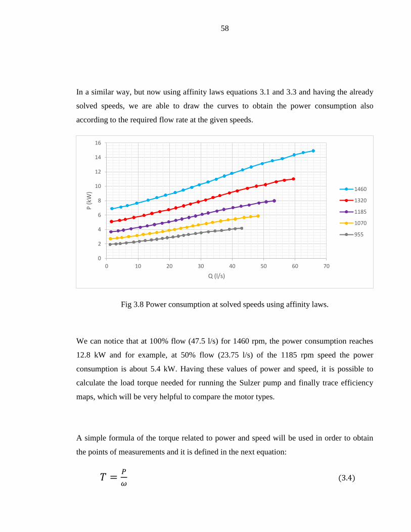
In a similar way, but now using affinity laws equations 3.1 and 3.3 and having the already
solved speeds, we are able to draw the curves to obtain the power consumption also
according to the required flow rate at the given speeds.
Fig 3.8 Power consumption at solved speeds using affinity laws.
We can notice that at 100% flow (47.5 l/s) for 1460 rpm, the power consumption reaches
12.8 kW and for example, at 50% flow (23.75 l/s) of the 1185 rpm speed the power
consumption is about 5.4 kW. Having these values of power and speed, it is possible to
calculate the load torque needed for running the Sulzer pump and finally trace efficiency
maps, which will be very helpful to compare the motor types.
A simple formula of the torque related to power and speed will be used in order to obtain
the points of measurements and it is defined in the next equation:
𝑇 =𝑃
𝜔 (3.4)
0
2
4
6
8
10
12
14
16
0 10 20 30 40 50 60 70
P (
kW)
Q (l/s)
1460
1320
1185
1070
955

59
where T is the torque in Nm, P is the power in watts and 𝜔 is the angular speed computed
with the formula:
𝜔 =2∗𝜋∗𝑟𝑝𝑚
60 (3.5)
rpm is the given speed, in our case, the different speeds that have been solved so far.
The most relevant results obtained so far are summarized in Table 3.2, expressed also as a
percentage of the SynRM nominal values.
Table 3.2 SynRM performance with the Sulzer pump.
Flow (l/s) Speed (rpm) Power (kW) Torque (Nm)
47.5 (100%) 1460 (97.3%) 12.8 (85.4%) 83.7 (88.1%)
35.62 (75%) 1320 (88%) 8.6 (57.5%) 62.4 (65.7%)
23.75 (50%) 1185 (79%) 5.4 (36.2%) 43.8 (46.1%)
11.87 (25%) 1070 (71.3%) 3.3 (22.1%) 29.6 (31.2%)
We can see clearly the advantage of using a motor driven by a VSD, for instance, to obtain
the maximum flow, we require 97.3% of the motor’s nominal speed, but in terms of power,
the energy consumption savings are noticeable, since it requires only 85% of the nominal
power. At half flow of the pump, the needed speed is around 80% of the nominal value and
the power consumption is now 36% when in the case of valve control the power
consumption would be around 9.3 kW (62%). In a similar way we can compare the shaft
torque requirements as a percentage of the nominal value, which is 95 Nm in the case of
this SynRM.
60
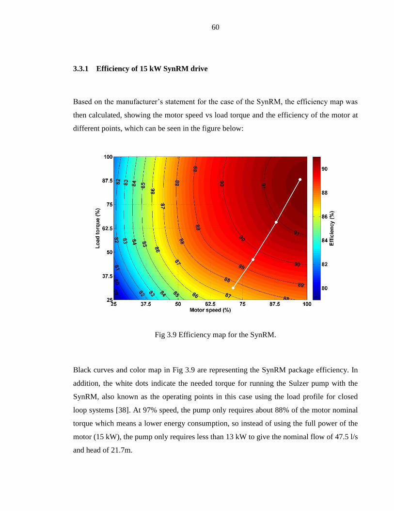
3.3.1 Efficiency of 15 kW SynRM drive
Based on the manufacturer’s statement for the case of the SynRM, the efficiency map was
then calculated, showing the motor speed vs load torque and the efficiency of the motor at
different points, which can be seen in the figure below:
Fig 3.9 Efficiency map for the SynRM.
Black curves and color map in Fig 3.9 are representing the SynRM package efficiency. In
addition, the white dots indicate the needed torque for running the Sulzer pump with the
SynRM, also known as the operating points in this case using the load profile for closed
loop systems [38]. At 97% speed, the pump only requires about 88% of the motor nominal
torque which means a lower energy consumption, so instead of using the full power of the
motor (15 kW), the pump only requires less than 13 kW to give the nominal flow of 47.5 l/s
and head of 21.7m.

61
We can see the efficiency values and needed speed and torque corresponding to the
operating points from Fig 3.9 shown in the table below.
Table 3.3 Operating points for the pump driven with a SynRM.
Speed (%) Torque (%) Efficiency (%) Input Power
(kW)
97.3 88.1 91.3 12.8
88 65.7 90.9 8.62
79 46.1 89.4 5.43
71.3 31.2 87.5 3.32
3.3.2 Efficiency of induction motor drive
In a similar way and using the results from the tests running inside LUT Laboratories, the
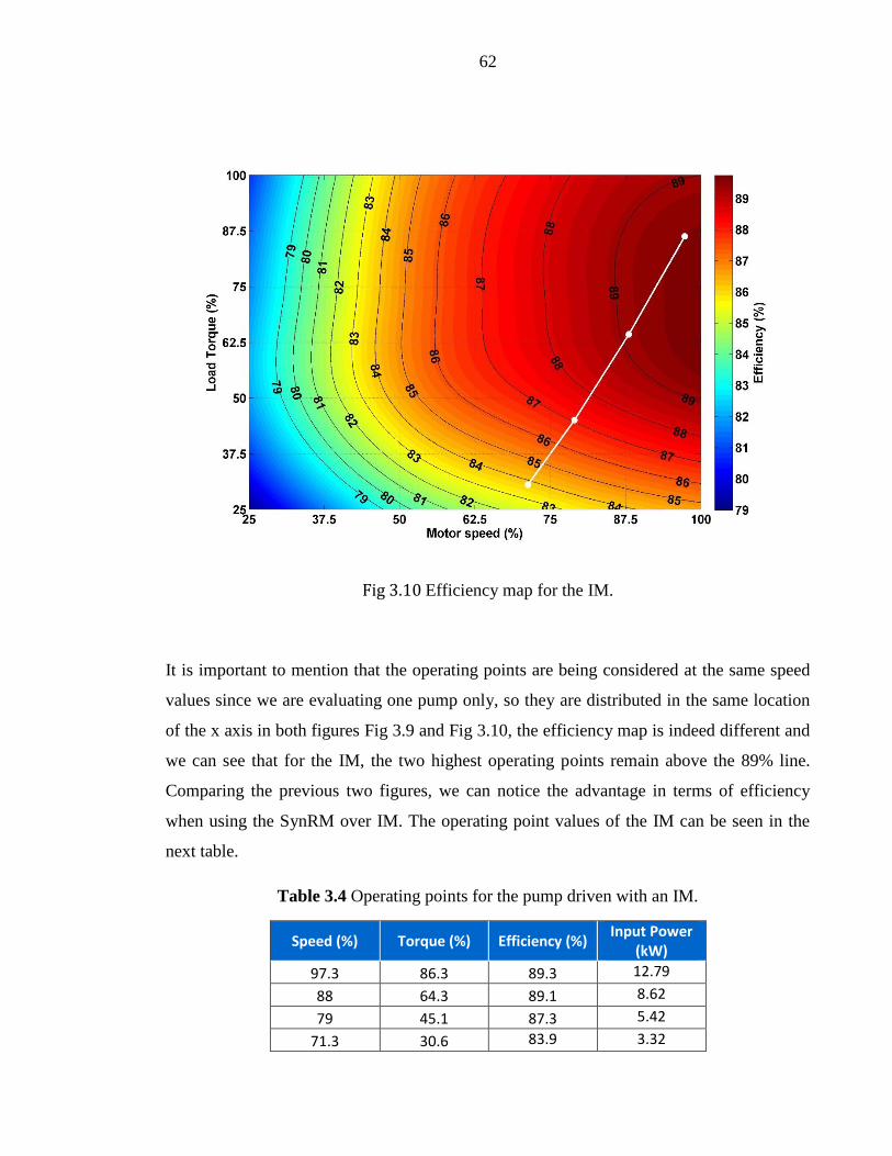
efficiency map for the induction motor was also obtained and it is shown in Fig 3.10.
62
Fig 3.10 Efficiency map for the IM.
It is important to mention that the operating points are being considered at the same speed
values since we are evaluating one pump only, so they are distributed in the same location
of the x axis in both figures Fig 3.9 and Fig 3.10, the efficiency map is indeed different and
we can see that for the IM, the two highest operating points remain above the 89% line.
Comparing the previous two figures, we can notice the advantage in terms of efficiency
when using the SynRM over IM. The operating point values of the IM can be seen in the
next table.
Table 3.4 Operating points for the pump driven with an IM.
Speed (%) Torque (%) Efficiency (%) Input Power
(kW)
97.3 86.3 89.3 12.79
88 64.3 89.1 8.62
79 45.1 87.3 5.42
71.3 30.6 83.9 3.32
63
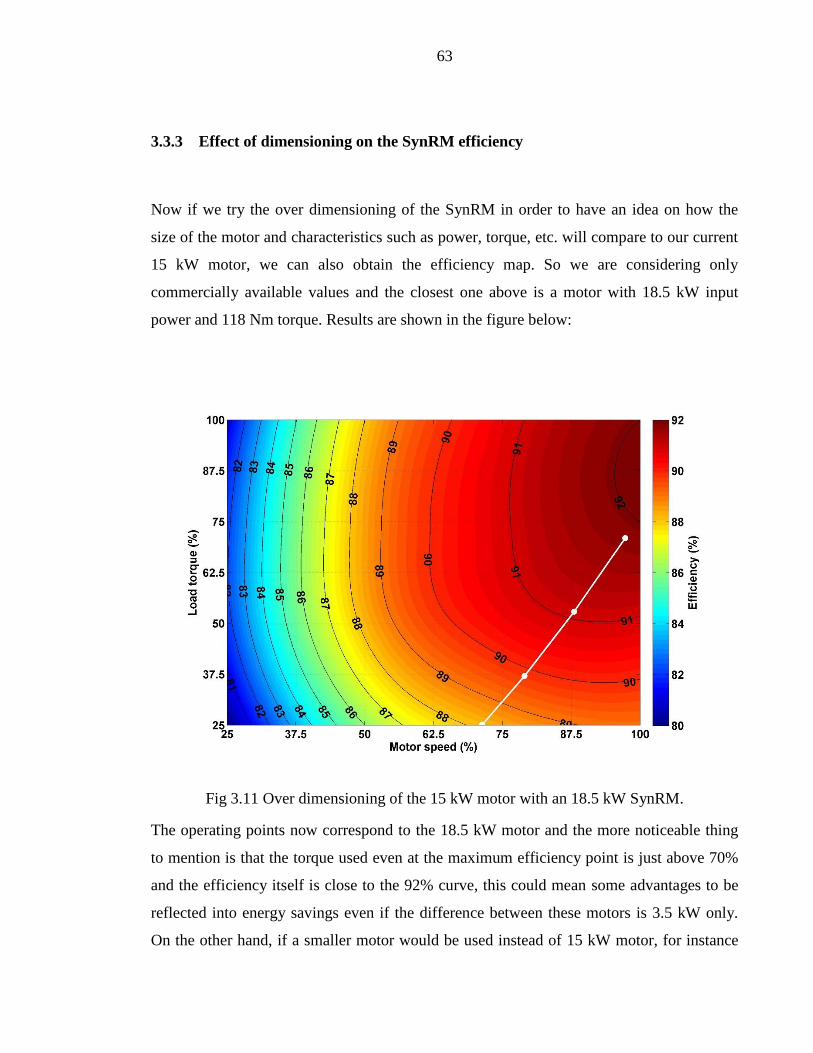
3.3.3 Effect of dimensioning on the SynRM efficiency
Now if we try the over dimensioning of the SynRM in order to have an idea on how the
size of the motor and characteristics such as power, torque, etc. will compare to our current
15 kW motor, we can also obtain the efficiency map. So we are considering only
commercially available values and the closest one above is a motor with 18.5 kW input
power and 118 Nm torque. Results are shown in the figure below:
Fig 3.11 Over dimensioning of the 15 kW motor with an 18.5 kW SynRM.
The operating points now correspond to the 18.5 kW motor and the more noticeable thing
to mention is that the torque used even at the maximum efficiency point is just above 70%
and the efficiency itself is close to the 92% curve, this could mean some advantages to be
reflected into energy savings even if the difference between these motors is 3.5 kW only.
On the other hand, if a smaller motor would be used instead of 15 kW motor, for instance

64
the next value commercially available would be 11 kW but the torque requirements go up
to 120% in order to fulfill the desired operating points’ efficiency.
The speed, torque, efficiency and input power of the 18.5 kW SynRM package are shown
below, according to the efficiency map from Fig 3.11:
Table 3.5 Operating points for the pump driven with the over dimensioned SynRM.
Speed (%) Torque (%) Efficiency (%) Input Power
(kW)
97.3 70.9 91.7 12.68
88 52.8 91.1 8.54
79 37.1 89.8 5.38
71.3 25.1 88.2 3.29
3.4 Results for 15 kW motors
With the results obtained so far, mainly the power consumption of the pump and the
package efficiency, we can determine the energy consumption values using the time
distribution for closed loop systems given in the table below:
Table 3.6 Time distribution for closed loop systems.
Flow (%) Time (%)
100 6
75 15
50 35
25 44
These values bring the idea on how the pump behaves in the closed loop systems, where it
usually is running only a small fraction of time on full flow and on the other side, most of
65
the time the pump is running on a low flow rate, which highlights the importance of using a
VSD so that the flow can be controlled at a certain speed to save energy.
In this study, we will consider the pump running a total of 4160 hours per year (47%) with
a calculated average power consumption of 6.06 kW, using the time distribution from Table
3.6 for the SynRM and information from Table 3.3, this brings a total of 25,222 kWh as a
total energy consumption through one year. In comparison with a fixed speed motor of the
same characteristics, the benefits of the SynRM are close to 13% less energy consumption.
With the same amount of hours per year, but with the average power for the IM with a VSD
calculated as 6.23 kW based on Table 3.4, the energy consumption in one year would be
25,933 kWh. Values for the PMSM were also estimated and a complete table showing all
of them will be used for comparison, based on the same time distribution and including the
energy costs per year considering the electricity price as 0.07 € per kWh:
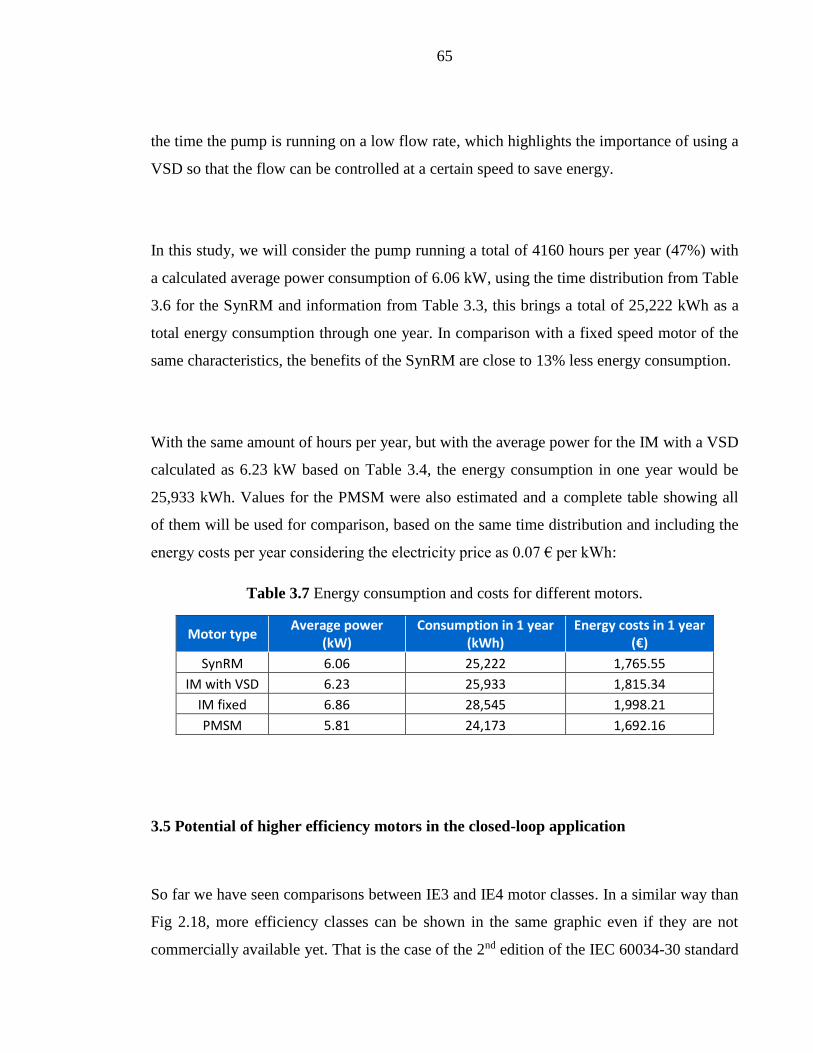
Table 3.7 Energy consumption and costs for different motors.
Motor type Average power
(kW) Consumption in 1 year
(kWh) Energy costs in 1 year
(€)
SynRM 6.06 25,222 1,765.55
IM with VSD 6.23 25,933 1,815.34
IM fixed 6.86 28,545 1,998.21
PMSM 5.81 24,173 1,692.16
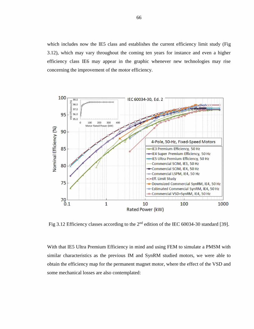
3.5 Potential of higher efficiency motors in the closed-loop application
So far we have seen comparisons between IE3 and IE4 motor classes. In a similar way than
Fig 2.18, more efficiency classes can be shown in the same graphic even if they are not
commercially available yet. That is the case of the 2nd edition of the IEC 60034-30 standard
66
which includes now the IE5 class and establishes the current efficiency limit study (Fig
3.12), which may vary throughout the coming ten years for instance and even a higher
efficiency class IE6 may appear in the graphic whenever new technologies may rise
concerning the improvement of the motor efficiency.
Fig 3.12 Efficiency classes according to the 2nd edition of the IEC 60034-30 standard [39].
With that IE5 Ultra Premium Efficiency in mind and using FEM to simulate a PMSM with
similar characteristics as the previous IM and SynRM studied motors, we were able to
obtain the efficiency map for the permanent magnet motor, where the effect of the VSD and
some mechanical losses are also contemplated:

67
Fig 3.13 Efficiency map for the PMSM.
Comparing the previous efficiency map with Fig 3.12, we can notice that this designed
PMSM fulfills the requirements for the IE5 class, where the 15 kW motor reaches almost
95% efficiency at its maximum peak. The operating points for the pump that has been part
of the study are also present on this efficiency map, where the majority of points are located
near and above the 93% efficiency line, this will of course be reflected as energy savings
since the pump will be running with an IE5 motor.
Table 3.8 Operating points for the pump driven with the designed PMSM.
Speed (%) Torque (%) Efficiency (%) Input Power
(kW)
97.3 88.1 94.5 12.79
88 65.7 93.8 8.63
79 46.1 93.3 5.43
71.3 31.2 92.5 3.32

68
Chapter 4
4 Comparison of resulting energy costs between the studied cases
On the economical side and according to Table 3.7, the energy costs during one year while
running the pump with the SynRM are about 1765 € and for a fixed speed motor it would
be almost 2000 €, of course the investment costs for the SynRM are higher because it
requires a separate VSD unit to operate, which is not needed for a fixed speed motor, but in
a longer term the benefits of using the motor and VSD together will translate into energy
cost savings and in this particular case of our study, even the CO2 savings can be estimated
with a value close to 3 tons during one year.
From Table 3.7 we can also conclude that the energy consumption compared to the IM
while running a VSD will be about 97% for the SynRM and close to 94% in the case of the
PMSM, hence this proves the difference between the efficiency classes IE3 (IM), IE4
(SynRM) and IE5 (PMSM).
In the coming figure we are doing a comparison on how these classes will compare with
each other in terms of the investment costs and through their annual energy consumption to
indicate at what stage a class payback time comes out and makes that class more profitable
than the other.

69
Fig 4.1 Motor efficiency classes and their annual energy consumptions.
The first thing to notice is that the IM fixed investment costs are smaller compared to the
other motors, but through a long period of time is the less reliable option since its energy
costs difference increases considerably. On the other hand, a PMSM considered as IE5 has
the higher investment costs but the payback time compared to the IM running a VSD is
about 5.5 years. The same IE5 motor becomes more reliable compared to the IE4 SynRM
after 6 years. An IE4 motor payback time is around 5 years compared to the IE3 induction
motor.
0
5 000
10 000
15 000
20 000
25 000
30 000
35 000
0 1 2 3 4 5 6 7 8 9 10 11 12 13 14 15
Co
sts
(€)
Time (years)
IM Fixed IM + VSD (IE3) SynRM (IE4) PMSM (IE5)

70
Now in terms of economy, another variable to analyze could be the Internal Rate of Return
(IRR), which can be estimated considering the variation of electricity prices in different
years [40] and gives the idea whenever a project is more reliable than other according to the
investment costs and the profit which varies year by year. In our case, those “projects” will
be simply the motors considering the aspects from the purchase price to the energy costs
through the years. IRR is calculated as a percentage where the higher value means the more
reliable a project is.
Considering a period of 10 years with the data taken from [40], purchase prices from Table
3.1 and energy costs from Table 3.7, the estimated IRR indicates that, compared to the IM
with VSD, the SynRM resulting value of 27% makes it more reliable than the PMSM with
a 20% IRR. So the SynRM would provide a better chance of strong growth.
71
Chapter 5
5 Conclusions
The implementation of a variable speed drive was proven to bring a considerable energy
saving potential for pumping systems while using a SynRM (considered as an IE4 class),
bringing a 2% higher efficiency than the IM (IE3 class). SynRM was also more suitable for
pumping applications because it is designed to work with a VSD and due to the frequency
changes, the variation of reactances affect the behavior of the IM which needs to be adapted
in order to work with a VSD.
It was shown that the effect of reducing the speed leads to a very large reduction in power
consumption. After solving the needed speeds and pump shaft power to realize the best
efficiency points of the pump, at full flow rate, the energy consumption was reduced by
15% from the 15 kW studied motor and the most remarkable difference was found at half
flow rate, reducing the power consumption around 60%.
Measurements and tests were successfully performed inside LUT laboratories, comparing
the efficiency results from the SynRM manufacturer’s declaration with the obtained ones
bringing less than 1% difference that can be justified according to the given tolerances from
the motor data sheet.
Efficiency maps were obtained representing the SynRM package efficiency indicating that
the pump only requires about 88% of the motor nominal torque according to the operating
points using the load profile for closed loop systems which translates into a lower energy
consumption. Efficiency maps for the IM and PMSM are also shown where the later one

72
data was obtained using FEM and simulations. The PMSM fulfilled the characteristics of
the higher efficiency class (IE5) contemplated at the moment, bringing the higher
efficiency within the three motor types.
The effect of dimensioning our 15 kW SynRM motor to a 18.5 kW one results in lower
load torque of about 70% at the maximum efficiency point and the efficiency itself is close
to the 92% curve, this could mean some advantages to be reflected into energy savings in a
long term period depending on the purchase price of each motor.
Further research can be done including a PMASynRM for comparison on the study of the
energy consumption whenever the commercial data, characteristics and purchase prices for
this type of motor are available.
IM investment costs are smaller compared to the other motors, but the overall energy costs
on a long period make it the less reliable option since its difference increases considerably.
PMSM has the higher investment costs but the payback time compared to the IM is about
5.5 years. An IE4 motor payback time is around 5 years compared to the IE3 induction
motor. The same PMSM motor becomes more reliable compared to the SynRM after 6
years.

73
Chapter 6
6 Summary
The majority of the motor electricity consumption takes place in pumping, fan and
compressor systems, representing more than 60% in the industrial sector and more than
80% in the services sector. Improvements in the system components, design and overall
fluid system operation can be done in order to increase the system energy efficiency. Of
these options, especially the use of variable-speed operation often provides the largest
energy saving potential for different fluid handling systems that further on can be translated
into Mtons reduction of CO2 emissions.
To achieve the sought improvements in the system components, some standards and
regulations are being adopted for fluid handling systems, like the Minimum Efficiency
Index (MEI) that limits the water pumps with less efficiency out of the European market on
the coming years. However, the European Association of Pump Manufacturers (Europump)
is aiming for a greater energy saving action by using a methodology to calculate the Energy
Efficiency Index (EEI) for the whole pumping system, including also the integrated pump
units such as circulator pumps.
Electric motors have a corresponding efficiency-based classification that in European
Union is based on International Efficiency (IE) classes. In order to introduce higher
efficiency motors into the market. Classes are labeled from IE1 to IE5 (indicative in the
latest revision of IEC 60034-30 standard).
74
This thesis studies the efficiency characteristics of existing electric motor types to
determine the effects of motor efficiency (IE class), motor sizing and changes in the
electricity price on the resulting energy consumption and costs in a pumping system. The
study is realized by determining the efficiency maps of 15 kW IM, SynRM and PMSM in
the context of a pumping system operating in the closed loop configurations.

75
References
[1] Market transformation of energy-efficient motor technologies in the EU. de
Almeida A., Fonseca P., Falkner H. and Bertoldi P. 2003. 6, s.l. : Energy Policy,
2003, Vol. 31.
[2] Implementing Directive 2009/125/EC of the European Parliament and of the
Council with regard to ecodesign requirements for water pumps. European
Commission. 2012. 547, s.l. : Official Journal of the European Union, 2012.
[3] European Association of Pump Manufacturers. 2013. Extended product
approach for pumps. Brussels : Europump, 2013.
[4] Modern comfort. Grundfos. 2012. http://moderncomfort.grundfos.com/int/heating-
hot-water/heating/magna3/#/features. [Online]
[5] Xylem. Flygt Experior. 2014. http://www.flygt.com/en-
us/Pumping/Experior/Pages/default.aspx. [Online]
[6] European Commission. 2003. European Guide to Pump Efficiency for Single
Stage Centrifugal Pumps. Brussels : Europump, 2003.
[7] Solovyeva, Elena. 2013. Mathematical Models and Stability Analysis of Induction
Motors under Sudden Changes of Load. Jyväskylä : Jyväskylä University Printing
House, 2013. ISBN 978-951-39-5521-2
[8] Juha Pyrhönen, Tapani Jokinen, Valéria Hrabovcová. 2008. Design of Rotating
Electrical Machines. Lappeenranta : John Wiley & Sons, 2008. ISBN: 978-0-470-
69516-6
[9] Azuara, Cosme Antonio. 2013. Accuracy Analysis of Frequency Converter
Estimates in Diagnostic Applications. Turku : s.n., 2013.
[10] Heikkilä, Tanja. 2002. Permanent Magnet Synchronous Motor for
Industrial Applications. Stockholm : s.n., 2002. ISBN 951-764-699-2.

76
[11] Pyrhönen, Juha. 2010. Electrical Drives course material. Lappeenranta :
Department of Electrical Engineering, 2010.
[12] ABB Motors and Generators. 2013. IE4 synchronous reluctance motor
and drive package for pump and fan applications. s.l. : ABB, 2013.
[13] Europump; Hydraulic Institute. 2004. Variable Speed Pumping a Guide to
Successful Applications. s.l. : Europump, 2004.
[14] ABB Switzerland Ltd. 2007. Motor bearings. Dättwil : ABB, 2007.
[15] Chapman, Stephen J. 1999. Electric Machinery Fundamentals. 3rd.
Boston : McGraw-Hill Science/Engineering/Math, 1999. ISBN:9780070119505.
[16] A Permanent Magnet-Assisted Synchronous Reluctance Motor. HIROSHI
MURAKAMI, YUKIO HONDA, SHIGEO MORIMOTO, YOJI TAKEDA.
2003. 4, Osaka : Electrical Engineering in Japan, 2003, Vol. 142.
[17] Liu, Tian-Hua. 2011. [bok section] Moulay Tahar Lamchich. Torque
Control. Rijeka, Croatia : InTech, 2011.
[18] Sulzer Pumps Ltd. 2014. New Hygienic Injection Pump Series. Winterthur,
Switzerland : Sulzer, 2014.
[19] Nidec Motor Corporation. 2013. TechDocs: Product Facts: Modern
Aluminum Alloys. Nidec Motor Corporation website. [Online] 2013.
http://www.usmotors.com/TechDocs/ProFacts/Aluminum-Alloys.aspx.
[20] Moghaddam, Reza - Rajabi. 2011. Synchronous Reluctance Machine
(SynRM) in Variable Speed Drives (VSD) Applications. Stockholm : The Royal
Institute of Technology, 2011. ISBN 978-91-7415-972-1.
[21] A Low-Cost and Efficient Permanent-Magnet-Assisted Synchronous
Reluctance Motor Drive. Peyman Niazi, Hamid A. Toliyat, Dal-Ho Cheong,
Jung-Chul Kim. 2007. Issue 2: IEEE, 2007, Volume 43.

77
[22] Analysis of Hybrid Permanent Magnet Assisted Synchronous Reluctance
Motor for Compressor. Yu, Minghu. 2013. Busan, Korea : Guangdong Meizhi
Compressor Limited, 2013.
[23] ABB Group. 2012. SynRM motor and drive package, Motor Summit. s.l. :
ABB, 2012.
[24] On-line Parameter Identification Scheme for Vector Controlled Drive of
Synchronous Reluctance Motor without Shaft Encoder. Mona Moussa, Yasser
Dessouky. 2013. Alexandria, Egypt : Global Advanced Research Journals, 2013,
Vol. 2. ISSN: 2315-5124.
[25] Performance Comparison of Permanent Magnet Synchronous Motor and
Induction Motor for Cooling Tower Application. H.K.Patel, Raj Nagarsheth,
Sharang Parnerkar. 2012. 8, Gujarat, India : International Journal of Emerging
Technology and Advanced Engineering, 2012, Vol. 2. ISSN 2250-2459.
[26] Comparison and design of different electrical machine types regarding their
applicability in hybrid electrical vehicles. Thomas Finken, Matthias Felden, Kay
Hameyer. 2008. Aachen, Germany : RWTH Aachen University, 2008.
[27] Design and Comparison of an Optimized Permanent Magnet-Assisted
Synchronous Reluctance Motor (PMa-SynRM) with an Induction Motor with
Identical NEMA Frame Stators. Robert Vartanian, Hamid A. Toliyat. 2009.
Texas : IEEE, 2009. 978-1-4244-3439-8.
[28] ABB. 2014. IEC 60034-30-1 standard on efficiency classes for low voltage
AC motors. Technical data. s.l. : ABB, 2014.
[29] Lenze Ltd. 2013. Using energy-efficient electric Motors. Meeting the
International Energy Directives. Bedford : Lenze Ltd, 2013.
[30] ABB. 2014. IE5 Ultra premium efficiency without rare earth magnets. s.l. :
ABB, 2014.

78
[31] KSB. 2013. KSB SuPremE – The World‘s Most Efficient Magnet-less Pump
Motor. Frankenthal : KSB Aktiengesellschaft, 2013.
[32] ABB. 2013. ACS850-04 Drive Modules Hardware Manual. 2013.
3AUA0000045496 Rev F.
[33] Reading Centrifugal Pump Curves. Satterfield, Zane. 2013. 1, West
Virginia : THE NATIONAL ENVIRONMENTAL SERVICES CENTER, 2013,
Vol. 12. DWFSOM155DL
[34] United Nations Environment Programme. 2006. Energy Efficiency Guide
for Industry in Asia. Energy Efficiency Asia. [Online] 2006.
www.energyefficiencyasia.org.
[35] The Motor Guide- basic technical The Motor Guide- basic technical motors.
ABB. 2005. 2nd edition, s.l. : ABB LV Motors, 2005. ISBN 952-91-0728-5
[36] A Modified Approach to Induction Motor Stator Voltage and Frequency
Control. . Cosmas Uchenna Ogbuka, Marcel U. Agu. 2009. 1, Nsukka, Nigeria :
The Pacific Journal of Science and Technology , 2009, Osa/vuosik. 10.
[37] Sebastian Lang, Gerhard Ludwig, Peter F. Pelz, Bernd Stoffel. 2013.
General Methodologies of Determining the Energy-Efficiency-Index of Pump Units
in the Frame of the Extended Product Approach. s.l. : Technische Universitat
Darmstadt, 2013.
[38] Comparison of electric motor types for realising an energy efficient pumping
system. Ahonen, Tero;Tamminen, Jussi; Montonen, Juho. 2014. Lappeenranta,
Finland : Lappeenranta University of Technology, 2014.
[39] Beyond Induction Motors—Technology Trends to Move Up Efficiency.
Almeida, Aníbal;Ferreira, Fernando ja Ge, Baoming. 2014. s.l. : IEEE
TRANSACTIONS ON INDUSTRY APPLICATIONS, 2014, Volume 50, No.3.
[40] 2015. Eurostat. Electricity prices by type of user. [Online] 28. 09 2015.
[Referenced: 07. 12 2015.]

79
http://ec.europa.eu/eurostat/tgm/table.do?tab=table&init=1&plugin=1&language=e
n&pcode=ten00117.
Top Related