


Languages
Pages
Legal

1/13
Gigabit Ethernet
Progressive Scan CCD Camera
KP-FD202GV Specifications Ver.1.00
1. General The KP-FD202GV is single CCD type RGB color camera which utilized the progressive scan CCD image sensor with square pixel for SXGA format of 1/1.8-inch which adopted the RGB primal color mosaic filter. By adoption of Gigabit Ethernet interface, high-speed connection of maximum of 1 Gbps can be possible. Moreover, by using hub or switcher, construction of multiple camera system can be easily performed.
2. Outstanding features (1) High resolution and color fidelity
The 1/1.8-inch 2,010,000 pixels square lattice progressive scan CCD and the RGB primary color mosaic filter achieve a high resolution and high color fidelity of 1620(H) x 1220(V) (UXGA).
(2) Gigabit Ethernet interface High-speed serial interface Gigabit Ethernet is supported and direct connection is possible to PC by the diameter cable of thin as compared with parallel output. It is possible to 100m.
(3) GigE Vision (Ver. 1.00) correspondence Based on Industrial camera interface standard GigE Vision, a maximum of 1Gbps high speed data transmit is available and suitable for image processing.
(4) GENiCAM (Ver. 1.00) correspondence Development of camera control system is easy because industrial camera control API "GENiCAM" lead EMVA (European Machine Vision Association).
(5) PoE correspondence Power supply can be input via Ethernet cable (Power over Ethernet).
(6) Remote control - Multi-step electronic shutter (from 1/30 to 1/50000 second in 8 steps) - Variable shutter (from 10 to 1/100000 second) - The image capture at desired timing using the external trigger signal - White balance (ATW, Manual and One-push) - 6 color independent masking (R, G, B, Cy, Mg, Ye can be independently varied) and other various functions are set by remote control via a Gigabit Ethernet cable.
GigE VisionTM and the distinctive logo are trademarks of AIA (Automated Imaging Association). GENiCAMTM is a trademark of EMVA (European Machine Vision Association). Ethernet is a trademark of XEROX Corporation.
2/13
3. Specifications
(1) Imaging device 1/1.8-inch progressive scan interline CCD Total pixels 1688 (H) x 1248 (V) Effective pixels 1628 (H) x 1236 (V) Pixel size 4.4 um (H) x 4.4 um (V) (square lattice) Color filter RGB primary color mosaic filter
(2) Scanning area 7.16 mm (H) x 5.44 mm (V) (3) Scanning system Progressive (4) Aspect ratio 4 : 3 (5) Frame rate 18 frames per second (full pixel readout RGB 8bit) (6) Sync system Internal / external (7) Lens mount C mount (8) Flange focal distance 17.526 mm (9) Video output
Interface Gigabit Ethernet Protocol GigE Vision compliant Transfer 1 Gbit per second Image format RGB 8/10/12bit YUV(4:2:2) 8/10/12bit RAW 8/10/12bit Mono 8/10/12bit Maximum image size 1620 (H) x 1220 (V) Frame rate 30 frame per second *Frame rate is different for following format RGB 8bit: 18 frame per second RGB 10bit: 12 frame per second RGB 12bit: 9 frame per second YUV 8bit: 28 frame per second YUV 10bit: 24 frame per second YUV 12bit: 24 frame per second RAW 10bit: 28 frame per second RAW 12bit: 28 frame per second
(10) Sensitivity 2000lx, F8, 3200K (11) Minimum illumination 10 lx (F1.4 GAIN MAX) (12) Electric shutter OFF / Auto (AES) / Manual (PRESET or VARIABLE) OFF is normal exposure (frame rate)
PRESET 1/30, 1/60, 1/100, 1/250, 1/1000, 1/2000, 1/10000, 1/50000 second.
VARIABLE 10 to 1/100000 second
3/13
(13) External trigger shutter
Mode Fixed shutter One trigger VD Sync Reset control
Input Via Gigabit Ethernet cable (Software trigger) 12-pin connector (Hardware trigger)
Input level 24Vp-p +/- 1V Threshold 3.7V +/- 0.5V (Low --> High) 3.3V +/- 0.5V (High --> Low) Input polarity High / Low adjustable Input delay Adjustable
(14) External sync signal VD output 5Vp-p +/- 0.3V Strobe out 5Vp-p +/- 0.3V Output polarity High / Low adjustable Strobe delay Adjustable Strobe duration Adjustable
(15) Partial scan Selectable start position and width of picture grabbing in 2H step. (16) ALC (Auto level control) Adjustable for video level (17) White balance ATW / MANUAL / One-push (18) Gain Auto / Manual (0dB to 12db) (19) Gamma OFF (γ=1) / ON (20) Color masking OFF / ON (6 vector independent masking) (21) Paint black Adjustable (22) Sharpness Adjustable (23) Black level Adjustable (24) Knee Adjustable (25) Power supply voltage DC+12V +/- 1V (input from 12-pin connector) 48V (PoE) (26) Current consumption Approx. 7.8W (DC+12V) When partial scan is on, Max Approx. 8.5W (DC+12V) (27) Ambient
Performance 0 to +40℃ (+32 to +104 F), less than 90 % RH Operation -10 to +50℃ (+14 to +122 F), less than 90 % RH Storage -20 to +60℃ (-4 to +140 F), less than 70 % RH (without dew condensation) Note : If operated continuously, be sure to use at less than +40℃ (+104F) for long term stable performance.
(28) Vibration endurance 98.6 m/s2 or less (10 to 200 to 15Hz, 30 minutes each on XYZ axes) (Do not subject to strong vibration for long periods of time.) (29) Shock endurance 490.3 m/s2 (Drop test, once each top, bottom, left and right) (30) External dimensions 44(W) x 29(H) x 72(D) mm (not including protrusions) (31) Mass Approx. 140g

4/13
5/13
4. Composition
(1) Camera (with IR cut filter) (2) CD-ROM (Operation manual, Control software and SDK) (3) Composition table
5. Optional accessories
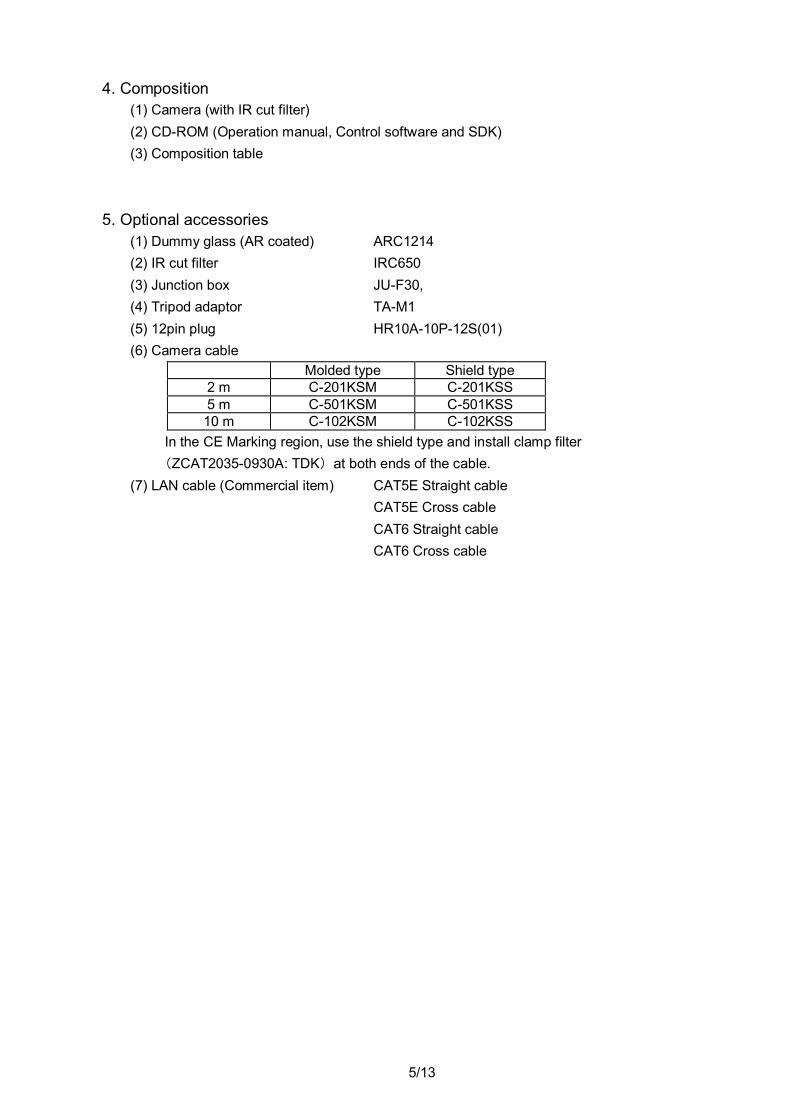
(1) Dummy glass (AR coated) ARC1214 (2) IR cut filter IRC650 (3) Junction box JU-F30, (4) Tripod adaptor TA-M1 (5) 12pin plug HR10A-10P-12S(01) (6) Camera cable
Molded type Shield type 2 m C-201KSM C-201KSS 5 m C-501KSM C-501KSS 10 m C-102KSM C-102KSS
In the CE Marking region, use the shield type and install clamp filter (ZCAT2035-0930A: TDK) at both ends of the cable.
(7) LAN cable (Commercial item) CAT5E Straight cable CAT5E Cross cable CAT6 Straight cable CAT6 Cross cable
6/13
6. Specification of Digital output connector
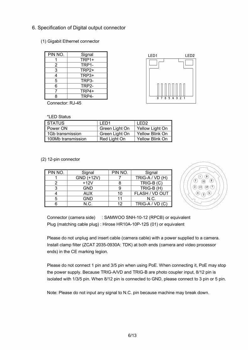
(1) Gigabit Ethernet connector
PIN NO. Signal 1 TRP1+ 2 TRP1- 3 TRP2+ 4 TRP3+ 5 TRP3- 6 TRP2- 7 TRP4+ 8 TRP4-
Connector: RJ-45 *LED Status
STATUS LED1 LED2 Power ON Green Light On Yellow Light On 1Gb transmission Green Light On Yellow Blink On 100Mb transmission Red Light On Yellow Blink On
(2) 12-pin connector
PIN NO. Signal PIN NO. Signal 1 GND (+12V) 7 TRIG-A / VD (H) 2 +12V 8 TRIG-B (C) 3 GND 9 TRIG-B (H) 4 AUX 10 FLASH / VD OUT 5 GND 11 N.C. 6 N.C. 12 TRIG-A / VD (C)
Connector (camera side) : SAMWOO SNH-10-12 (RPCB) or equivalent Plug (matching cable plug) : Hirose HR10A-10P-12S (01) or equivalent Please do not unplug and insert cable (camera cable) with a power supplied to a camera. Install clamp filter (ZCAT 2035-0930A: TDK) at both ends (camera and video processor ends) in the CE marking legion. Please do not connect 1 pin and 3/5 pin when using PoE. When connecting it, PoE may stop the power supply. Because TRIG-A/VD and TRIG-B are photo coupler input, 8/12 pin is isolated with 1/3/5 pin. When 8/12 pin is connected to GND, please connect to 3 pin or 5 pin. Note: Please do not input any signal to N.C. pin because machine may break down.
LED1 LED2
7/13
7. Timing chart
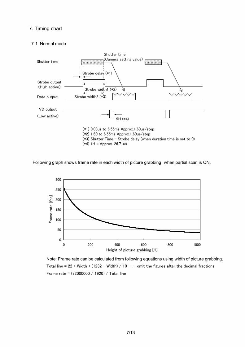
7-1. Normal mode
Following graph shows frame rate in each width of picture grabbing when partial scan is ON.
Note: Frame rate can be calculated from following equations using width of picture grabbing. Total line = 22 + Width + (1232 - Width) / 10 ・・・ omit the figures after the decimal fractions
Frame rate = (72000000 / 1920) / Total line
(*1) 0.08us to 6.55ms Approx.1.60us/step (*2) 1.60 to 6.55ms Approx.1.60us/step (*3) Shutter Time – Strobe delay (when duration time is set to 0) (*4) 1H = Approx. 26.71us
0
50
100
150
200
250
300
0 200 400 600 800 1000
Height of picture grabbing [H]
Fra
me r
ate [
fps]
Shutter time
Shutter time (Camera setting value)
Data output
Strobe output (High active)
Strobe width2 (*3)
VD output
(Low active)
Strobe width1 (*2)
Strobe delay (*1)
9H (*4)
8/13
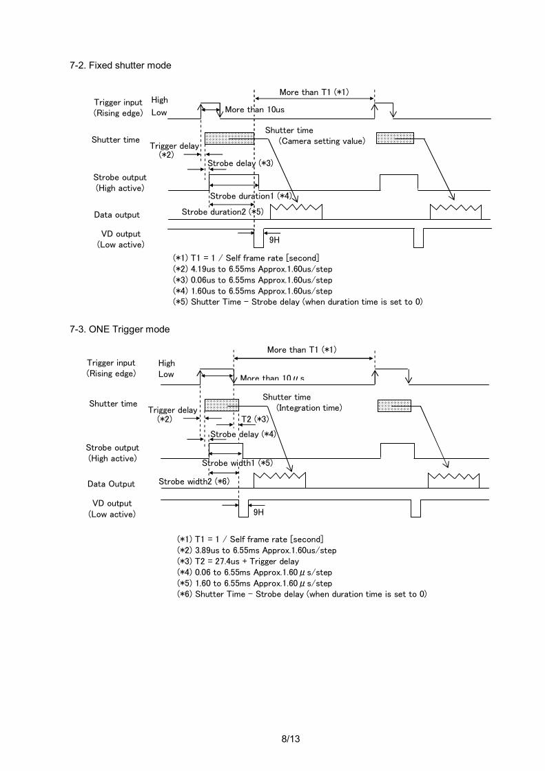
7-2. Fixed shutter mode
7-3. ONE Trigger mode
Trigger input (Rising edge)
High
Low
Shutter time Shutter time (Camera setting value)
Data output
More than T1 (*1)
Strobe output (High active)
Trigger delay (*2)
VD output (Low active)
9H
Strobe delay (*3)
Strobe duration1 (*4)
Strobe duration2 (*5)
More than 10us
(*1) T1 = 1 / Self frame rate [second] (*2) 4.19us to 6.55ms Approx.1.60us/step (*3) 0.06us to 6.55ms Approx.1.60us/step (*4) 1.60us to 6.55ms Approx.1.60us/step (*5) Shutter Time – Strobe delay (when duration time is set to 0)
Trigger input (Rising edge)
High Low
Shutter time Shutter time (Integration time)
Data Output
More than 10μs
More than T1 (*1)
T2 (*3)
Strobe output (High active)
Trigger delay (*2)
Strobe width2 (*6)
VD output (Low active) 9H
Strobe width1 (*5)
Strobe delay (*4)
(*1) T1 = 1 / Self frame rate [second] (*2) 3.89us to 6.55ms Approx.1.60us/step (*3) T2 = 27.4us + Trigger delay (*4) 0.06 to 6.55ms Approx.1.60μs/step (*5) 1.60 to 6.55ms Approx.1.60μs/step (*6) Shutter Time – Strobe delay (when duration time is set to 0)
9/13
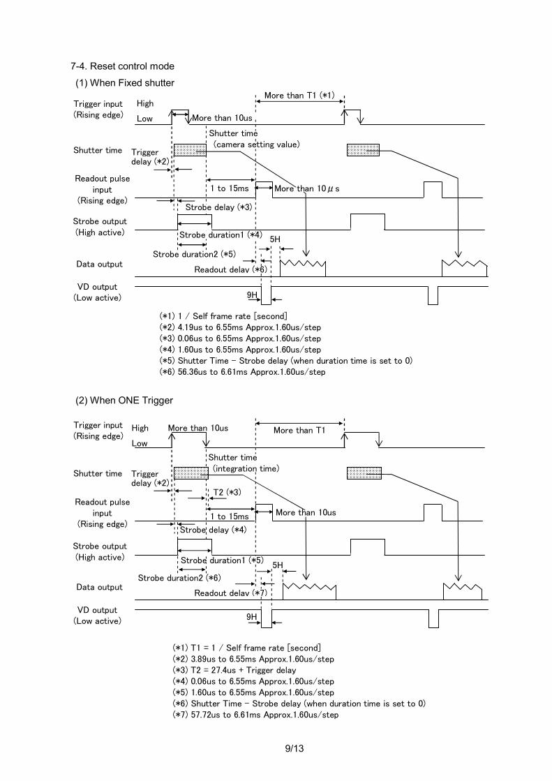
7-4. Reset control mode
(1) When Fixed shutter
(2) When ONE Trigger
(*1) 1 / Self frame rate [second] (*2) 4.19us to 6.55ms Approx.1.60us/step (*3) 0.06us to 6.55ms Approx.1.60us/step (*4) 1.60us to 6.55ms Approx.1.60us/step (*5) Shutter Time – Strobe delay (when duration time is set to 0) (*6) 56.36us to 6.61ms Approx.1.60us/step
(*1) T1 = 1 / Self frame rate [second] (*2) 3.89us to 6.55ms Approx.1.60us/step (*3) T2 = 27.4us + Trigger delay (*4) 0.06us to 6.55ms Approx.1.60us/step (*5) 1.60us to 6.55ms Approx.1.60us/step (*6) Shutter Time – Strobe delay (when duration time is set to 0) (*7) 57.72us to 6.61ms Approx.1.60us/step
Trigger input (Rising edge)
Shutter time
Readout pulse input
(Rising edge)
Strobe output (High active)
Data output
More than 10us
T2 (*3)
More than T1
5H
1 to 15ms
VD output (Low active)
Trigger delay (*2)
Strobe delay (*4)
Strobe duration2 (*6)
More than 10us
Shutter time (integration time)
Strobe duration1 (*5)
High
Low
9H
Readout delay (*7)
Trigger input (Rising edge)
Shutter time
Readout pulse input
(Rising edge)
Strobe output (High active)
Data output
More than T1 (*1)
5H
1 to 15ms
VD output (Low active)
Trigger delay (*2)
Strobe duration2 (*5)
High
Low Shutter time (camera setting value)
More than 10μs
Strobe delay (*3)
Strobe duration1 (*4)
More than 10us
9H
Readout delay (*6)
10/13
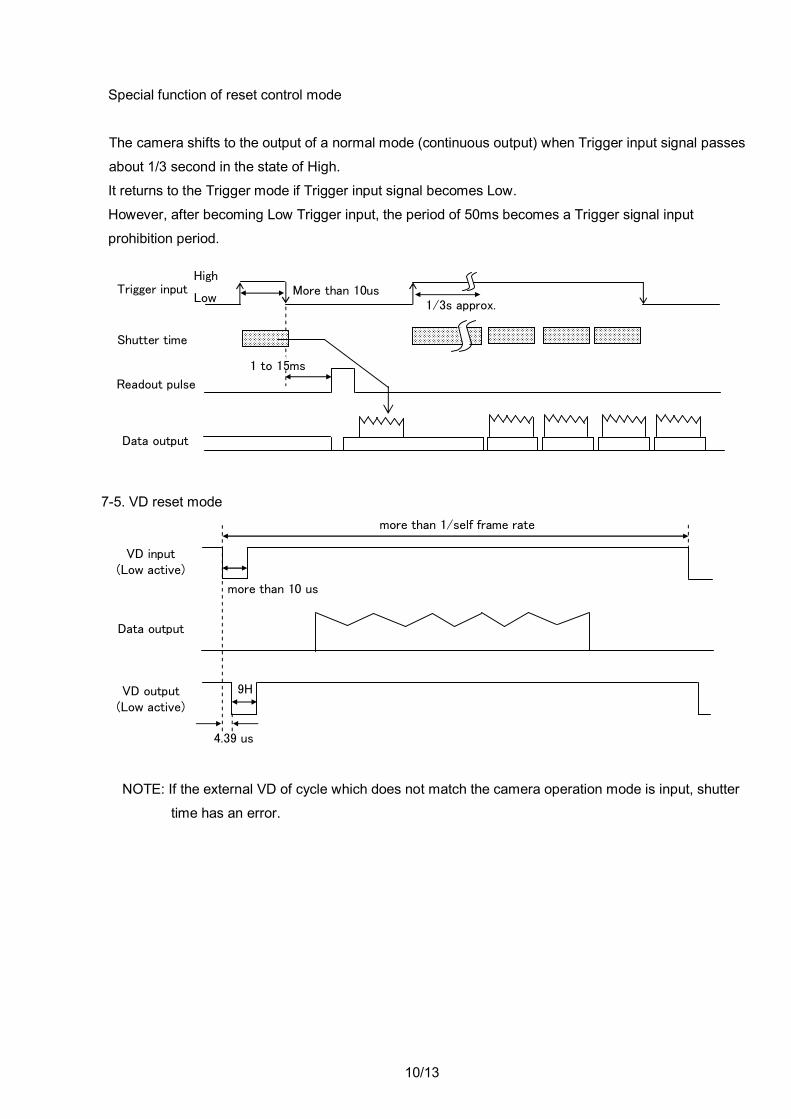
Special function of reset control mode
The camera shifts to the output of a normal mode (continuous output) when Trigger input signal passes
about 1/3 second in the state of High.
It returns to the Trigger mode if Trigger input signal becomes Low.
However, after becoming Low Trigger input, the period of 50ms becomes a Trigger signal input
prohibition period.
7-5. VD reset mode
NOTE: If the external VD of cycle which does not match the camera operation mode is input, shutter
time has an error.
Trigger input High
Low
Shutter time
Data output
More than 10us
Readout pulse
1/3s approx.
1 to 15ms
9H
more than 10 us
more than 1/self frame rate
VD input (Low active)
Data output
VD output (Low active)
4.39 us
11/13
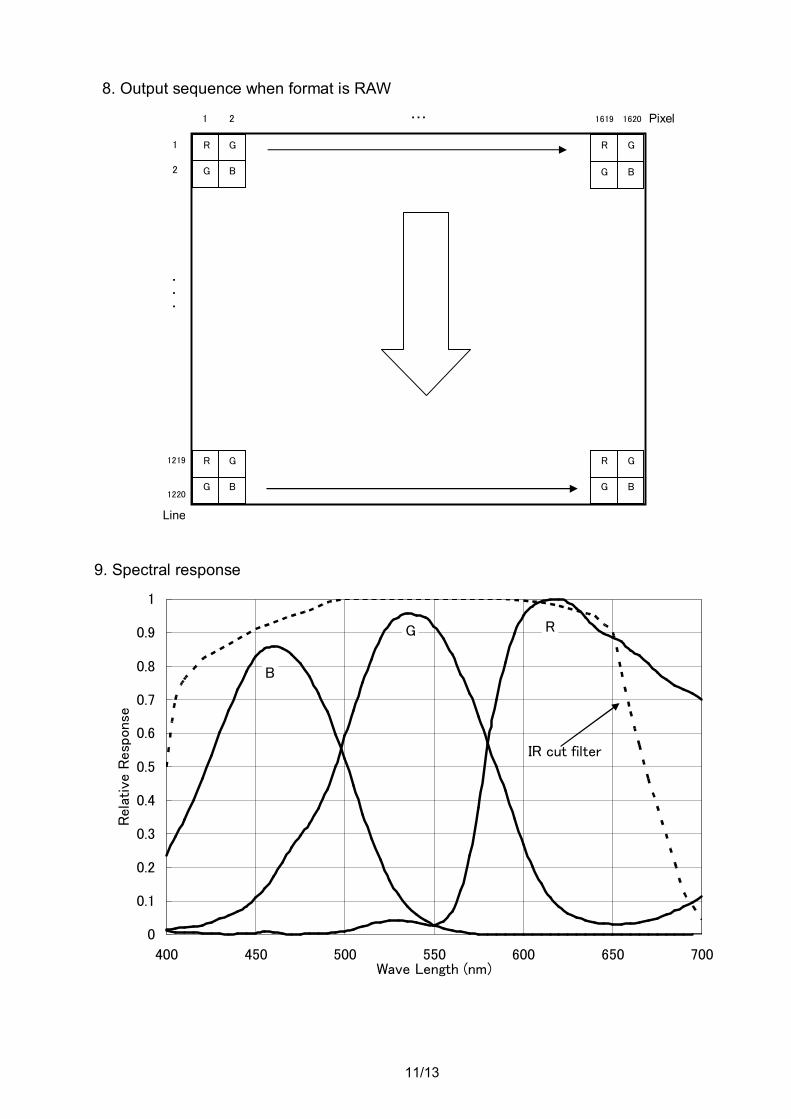
8. Output sequence when format is RAW 9. Spectral response
R
1 2 ・・・ 1619 1620
1
1220
G R G
・ ・
・
2
Pixel
G B G B
Line
G B G B
R G R G 1219
0
0.1
0.2
0.3
0.4
0.5
0.6
0.7
0.8
0.9
1
400 450 500 550 600 650 700Wave Length (nm)
Rela
tive
Resp
onse
B
G R
IR cut filter
12/13
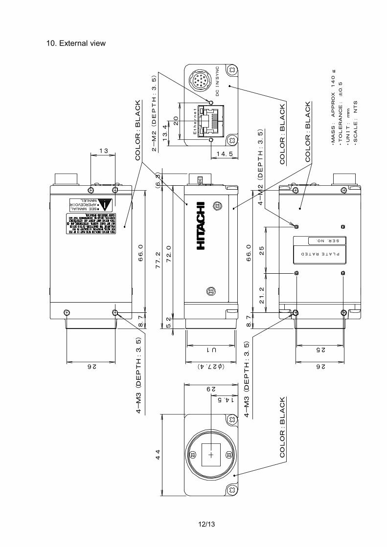
10. External view
PLATE RATED
SER.NO.
DC I
N/S
YNC
Ethernet
U1
26 (φ27.4)
72.0
77.266.0
8.7
29
14.5
4-M3(DEPTH:3.5
)
25
26
21.2
66.0
8.7
25
4-M2(DEPTH:3.5
)
4-M3(DEPTH:3.5
)
5.2
44
(6.3
)
COLOR:BLACK
COLOR:BLACK
COLOR:BLACK
13
SEE MANUALAPERCEVOIRMANUEL
・MASS: APPROX 140 g
・TOLERANCE: ±0.5
・UNIT: mm
・SCALE: NTS
2-M2(DEPTH:3.5)
13.4
20
14.5
COLOR:BLACK
13/13
Warranty and service:
(1) The guarantee period is one year after the data purchase. However, the defects due to erroneous use or intentional act are excluded.
(2) As the defect after expiration of the guarantee period, where product repair is possible, repair will be performed at charge.
(3) The present Warranty pertains only to the camera unit. Secondary malfunctions attributable to camera failure as well as expenses incurred by disassembly and reassembly of the related system, are beyond the scope of this Warranty.
(4) Compensation for loss of business, loss or damage to software, database and other contingent losses are beyond the scope of this Warranty.
(5) Hitachi Kokusai Electric Inc. is not liable for the losses caused when the equipment is used in a system, use for business trades, production process, medical fields, crime prevention applications, etc.
(6) In the case of camera trouble by miss wiring of cable, it will be considered as out of warranty.
RoHS Compliant This product complies with the requirement of the RoHS(Restriction of the use of Certain Hazardous Substances in Electrical and Electronic Equipment) Directive 2002/95/EC
Notice: These specifications are subject to change without prior notice due to product improvement. Confirm the most recent specifications at time of order. Hitachi Kokusai certifies this product complies with the standard warranty conditions of Hitachi Kokusai, and that quality control is implemented to the extent required to comply with these conditions.
Top Related