


Languages
Pages
Legal


Kilovoltage X-RKilovoltage X Rfor Radiatio
C M ChC.-M. ChDept. of Radiation Oncolog
Clinical Dosimetry Meay2009 AAPM
ColoradoJune 2
Ray DosimetryRay Dosimetry on Therapy
h li Mharlie Magy, FCCC, Philadelphia, PA
asurements in RadiotherapypySummer School
o College, CO1-25, 2009
OutlOutlKil lt d Kilovoltage x-ray do
TG-61 formalism for TG-61 formalism for
Clinical implementatp
Summary of TG-61 r
Uncertainty analysis
linelinei t iosimetry- a review
r kilovoltage x-ray dosimetryr kilovoltage x-ray dosimetry
tion of the TG-61 protocolp
recommendations
s
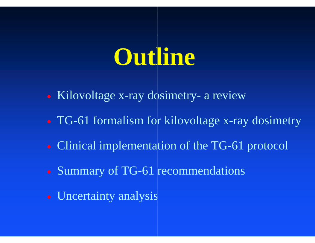
Therapax HF150 SuperfTherapax HF150 Superfficial Unit By Pantak, Incficial Unit By Pantak, Inc

A X-ray unit from GA X ray unit from GGulmay Medical LtdGulmay Medical Ltd
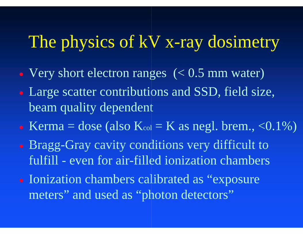
The physics of kV
Very short electron rangL tt t ib ti Large scatter contributiobeam quality dependent
Kerma = dose (also Kcol
Bragg Gray cavity cond Bragg-Gray cavity condfulfill - even for air-fille
Ionization chambers calmeters” and used as “php
V x-ray dosimetry
ges (< 0.5 mm water)d SSD fi ld ions and SSD, field size,
tl = K as negl. brem., <0.1%)ditions very difficult toditions very difficult to ed ionization chamberslibrated as “exposure hoton detectors”

Kil lt dKilovoltage x-ray d
Kilovoltage x-ray dosimetry 70 years following the discov70 years following the discov
The introduction of the roentCongress of Radiology markphysical measurement of rad
The universally adopted instri h f i h b (±1%is the free air chamber (±1%labs in 1932)
d i t idosimetry- a review
is the main theme in the first very of x-raysvery of x rays
tgen in 1928 at Stockholm gked the beginning of precise diation exposure (dose)
rument to measure exposure % b i l% agreement between national

Exposure, X
dQdd QX dm
where dQ is the absolute valuions of one sign produced in electrons liberated by photoncompletely stopped in air
kg/c)(
ue of the total charge of the (dry) air when all the
ns in air of mass dm are

Measurement ofMeasurement of
Free Air Ch
f Exposuref Exposure
QX LA
XD
D
hamber

“Modern” Dosimetry f
ICRU Report 23 (1973) sp ( )40-150 kV in-air method
NCRP Report 69 (1981) 10 kV and above, in-air10 kV and above, in air
IAEA Report 277 (1987)IAEA Report 277 (1987)10-100 kV in-air method
for Kilovoltage X-Ray
significant changes madeg gd, >150 kV in-phantom
only protocol for N. Ame.method, no BSF givenmethod, no BSF given
significant changes made significant changes maded, >100 kV in-phantom

“Modern” Dosimetry f
IPEMB Code of Practice (V l ( 1 Al) iVery low- (< 1mmAl) in-pin-air, medium-energy (>0
NCS Code of Practice (19950 - 100 kV in-air method
d f i ( IAEA Code of Practice (20Absorbed dose based, con
for Kilovoltage X-Ray
1996) with three rangesh l (1 8 Al)phantom, low- (1-8mmAl)
0.5mmCu) in-phantom
97) two energy rangesd, 100 - 300 kV in-phantom
) d i000) - new recommendationsnsistent with other beams

Kilovoltage x
For low energy (40 For low-energy (40 x-rays - the backsca
F di For medium-energyHVL) x-rays - the in) y
(except for NC
-ray dosimetry
150 kV 8mm Al HVL)- 150 kV, 8mm Al HVL)atter method
(100 300 kV 4 Cy (100 - 300 kV, 4mm Cun-phantom MethodpCRP Report 69)

AAPM TG( Med. Phys.
893 )893 )
Charles Coffey Chihray Liu Ravi Nath Jan SeuntjensJan Seuntjens
G-61 Report28 (6) 2001 868-
Larry DeWerd Charlie Ma (chair)Stephen Seltzer
What’s New in AW at s New
U b th th i i d Use both the in-air and potentials 100 - 300 kV
More complete data (fo
Recommendations for r
Recommendations for Q
AAPM TG-61?G 6 ?
i h t th d f t bin-phantom methods for tube V
or water, tissue & bone)
relative measurements
QA and consistency check
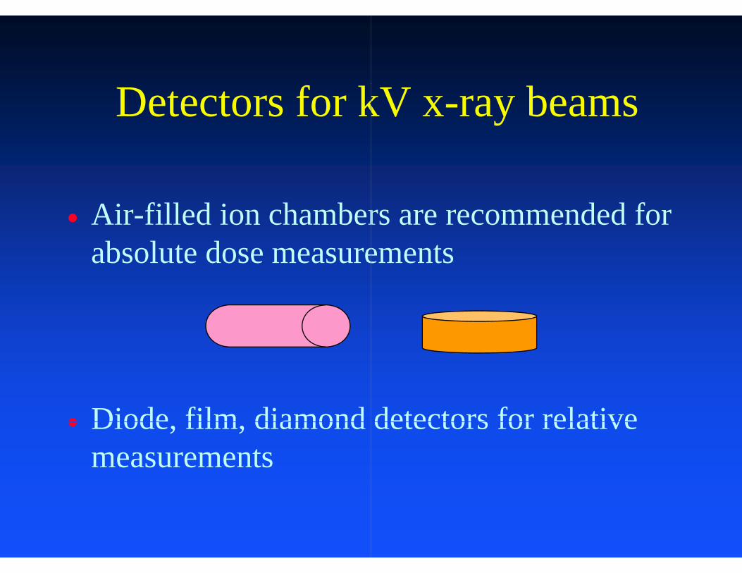
Detectors for k
Air-filled ion chamber Air filled ion chamberabsolute dose measure
Diode film diamond Diode, film, diamond measurements
kV x-ray beams
rs are recommended forrs are recommended for ements
detectors for relativedetectors for relative
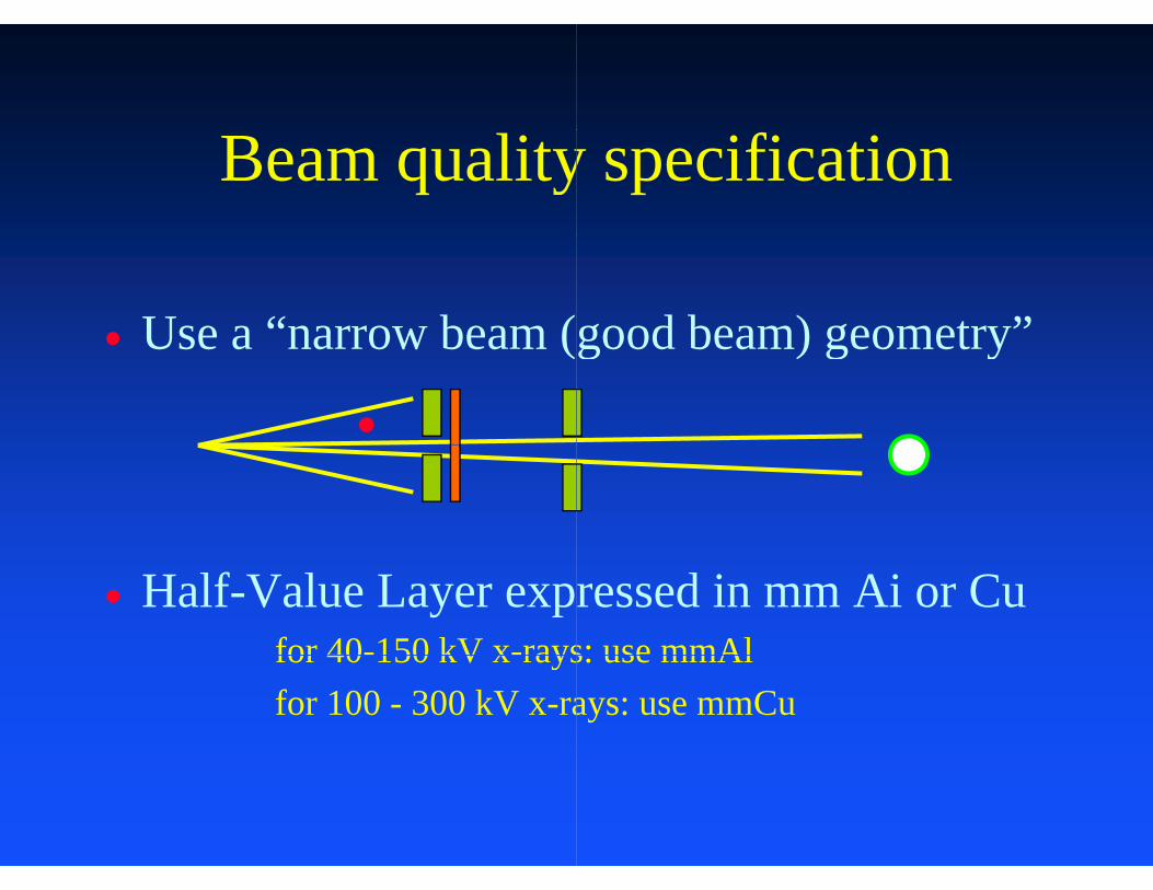
Beam quality
Use a “narrow beam ( Use a narrow beam (
●
Half-Value Layer exprfor 40-150 kV x-raysfor 40 150 kV x raysfor 100 - 300 kV x-ra
y specification
good beam) geometry”good beam) geometry
ressed in mm Ai or Cus: use mmAls: use mmAl ays: use mmCu

300
kV)
ntia
l (k
200
be p
oten
100
Tub 100
1 2HVL (m
3 4mmCu)
Beam quality
Use both tube potentia Use both tube potentiabeam quality for cham
Use HVL to specify bUse HVL to specify bdetermination of chamconversion factorsconversion factors
y specification
al and HVL to specifyal and HVL to specify mber calibration
eam quality foream quality for mber correction and

Table 1: UW ADCL and NIST beams co
NIST BEAM QUALITIES
BEAM HVL HCCode (mm Al)L30 0.22 60L40 0.49 57L50 0.75 58L80 1.83 58
L1001 2.8 59
M20 0.152 79M30 0.36 64M40 0.73 66M50 1.02 66M60 1.68 68
M100 5.0 72
M150 10.2 87M200 14 9 95M200 14.9 95M250 18.5 98
S75 1.86 63S60 2 8 75S60 2.8 75
All beams are matched as closely as possible to
ompared.
UW ADCL BEAM QUALITIES
BEAM HVL HCCode (mm Al)UW30-L 0.22 56UW40-L 0.49 60UW50-L 0.75 61UW80-L 1.83 58UW100-L 2.80 58
UW20-M 0.153 79UW30-M 0.354 63UW40-M 0.73 64UW50-M 1.02 64UW60-M 1.68 66
UW80 M2 2.96 68UW80-M2 2.96 68UW100-M 4.98 72
UW120-M2 6.96 78UW150-M 10.2 87UW200 M 14 9 94UW200-M 14.9 94UW250-M 18.5 98
UW75-S 1.86 63UW60 S 2 82 76UW60-S 2.82 76
o available NIST beam qualities.

I i ti ChIonization Cham
Free-in-air Kair calibra
KN KN aK
Free-in-air X calibration
XN XN X
-1)-(1)/( geWNN air )-(1)/( geWNN XK
b C lib timber Calibration
ation
/ M/ Mair
n
/ MX / MXChamber stem ef
-1)-(1)/( geWXK air )-(1)/( geWXKair

in air
1.6
in air
1.3
1.4
1.5
1.0
1.1
1.2
0.7
0.8
0.9
0.4
0.5
0.6
50 100 150
/ kV
0.2
0.3
energy / kV
Farm
RK
NACPNACP
CapinCap
diode
N23342
200 250 300Markus
p

1.6
1.4
1.0
1.2
0.8
0.4
0.6
50 100 150 2000.2
Farmer
RKRK
NACP
Diode
Capintec
N23342
Markus
250 300 Spokas
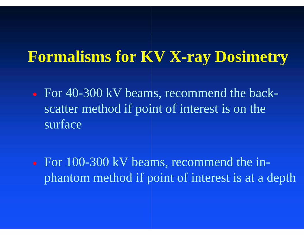
Formalisms for Ko a s s o
F 40 300 kV b For 40-300 kV beamscatter method if poisurface
For 100-300 kV beamh h d ifphantom method if p
KV X-ray DosimetryV ay os et y
d th b kms, recommend the back-nt of interest is on the
ms, recommend the in-i f i i d hpoint of interest is at a depth

110
100
0 190
depth / g/cm2
RK
NACP
diode
Farmer
S kSpokas
TLD
N23342
2
Markus
Capintec
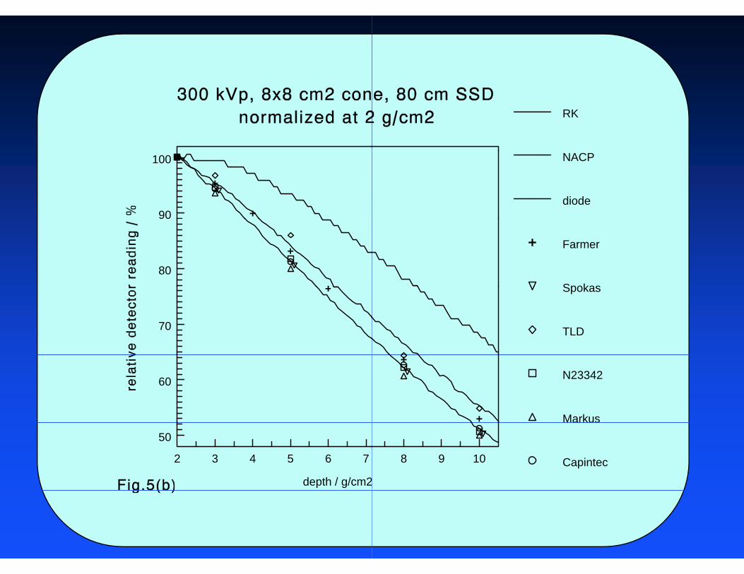
90
100
80
70
60
2 3 4 5 6 7
depth / g/cm2
50
RK
NACP
diode
Farmer
SpokasSpokas
TLD
N23342
Markus
8 9 10 Capintec

Th B k ttThe Backscatter
For surface dose deter
eKw MND (
(i i ) M th dr (in-air) Method
rmination
wairstemen BP ,wair )/
●

D i ti f th B kDerivation for the Back
Determine the air kerma at achamber airin
i MK
Convert air kerma to water k
air MK
iii
Derive water kerma on the su
inair
airinw KK
Derive absorbed dose to wat
w KK
Derive absorbed dose to watcharged particle equilibrium
KD ww KD
k tt (I i ) M thkscatter (In-air) Metho
a point in air in absence of the
iPMNK
kerma by
airstem,PMNK
i
urface using a backscatter factor)/( w
airenair-n
r
ter from water kerma assuming
wairin
w BK
ter from water kerma assuming
existsCPE existsCPEw
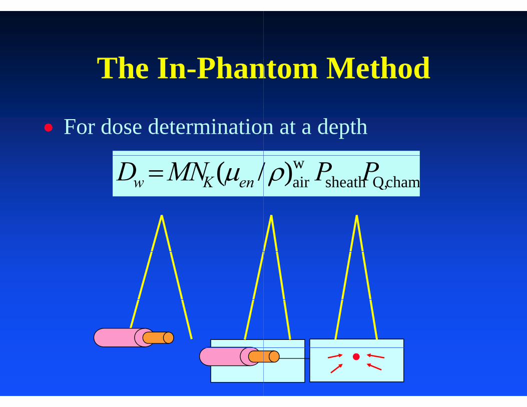
Th I PhThe In-Phan
For dose determination
/( MND enKw
t M th dntom Method
n at a depth
chamQ,sheathwair )/ PP
●
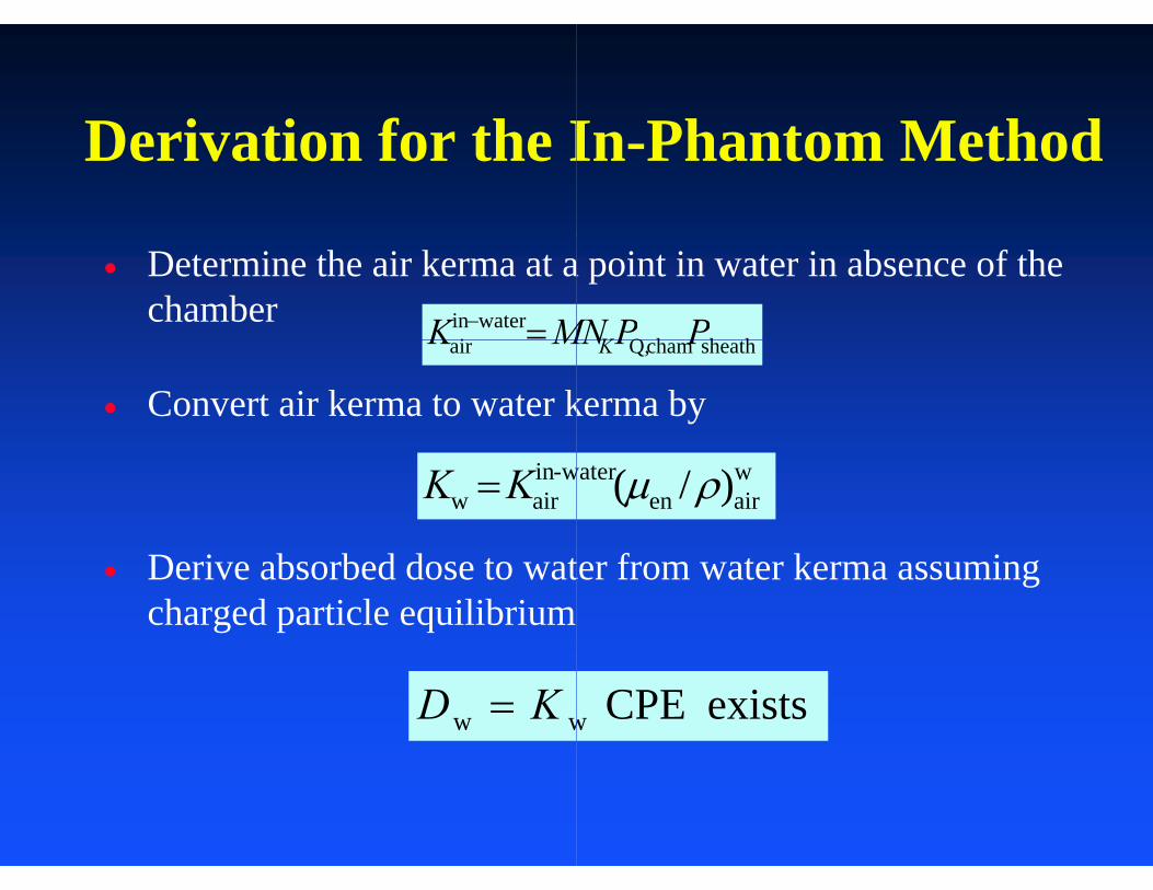
D i ti f th IDerivation for the I
Determine the air kerma at achamber waterin
i MK
Convert air kerma to water k
air MK
w-inairw KK
Derive absorbed dose to watcharged particle equilibrium
ww KD
I Ph t M th dIn-Phantom Method
a point in water in absence of the
h hhQ PPMNK
kerma by
sheathchamQ, PPMNK
)/( wairen
water
ter from water kerma assuming
exists CPE w
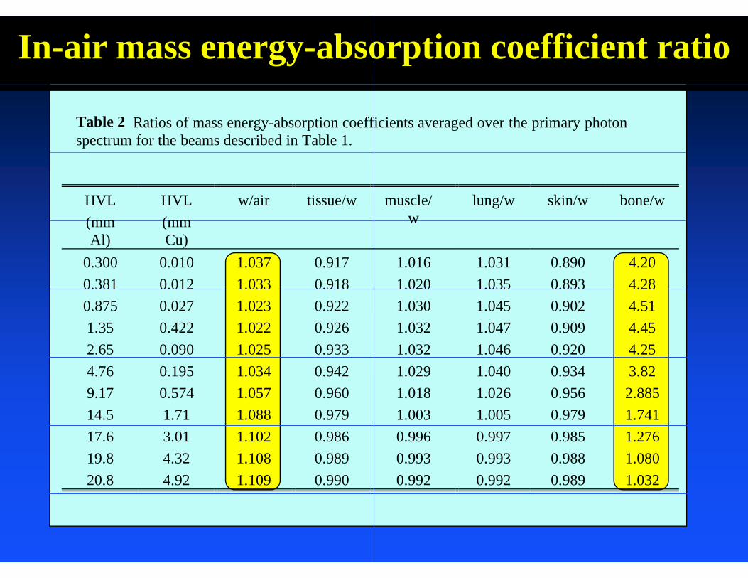
In-air mass energy-abso
Table 2 Ratios of mass energy-absorption coeffspectrum for the beams described in Table 1.
HVL(mm
HVL(mm
w/air tissue/w(mmAl)
(mmCu)
0.300 0.010 1.037 0.9170.381 0.012 1.033 0.9180.381 0.012 1.033 0.9180.875 0.027 1.023 0.9221.35 0.422 1.022 0.9262.65 0.090 1.025 0.9334.76 0.195 1.034 0.9429.17 0.574 1.057 0.96014.5 1.71 1.088 0.97917.6 3.01 1.102 0.98619.8 4.32 1.108 0.98920.8 4.92 1.109 0.990
orption coefficient ratio
ficients averaged over the primary photon
muscle/w
lung/w skin/w bone/ww
1.016 1.031 0.890 4.201.020 1.035 0.893 4.281.020 1.035 0.893 4.281.030 1.045 0.902 4.511.032 1.047 0.909 4.451.032 1.046 0.920 4.251.029 1.040 0.934 3.821.018 1.026 0.956 2.8851.003 1.005 0.979 1.7410.996 0.997 0.985 1.2760.993 0.993 0.988 1.0800.992 0.992 0.989 1.032
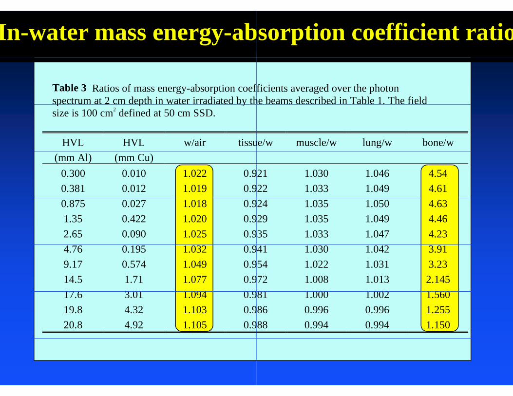
In-water mass energy-ab
Table 3 Ratios of mass energy-absorption coefspectrum at 2 cm depth in water irradiated by thp p ysize is 100 cm2 defined at 50 cm SSD.
HVL HVL w/air tissu(mm Al) (mm Cu)
0.300 0.010 1.022 0.90.381 0.012 1.019 0.90.875 0.027 1.018 0.91.35 0.422 1.020 0.92.65 0.090 1.025 0.94.76 0.195 1.032 0.99.17 0.574 1.049 0.914.5 1.71 1.077 0.917 6 3 01 1 094 0 917.6 3.01 1.094 0.919.8 4.32 1.103 0.920.8 4.92 1.105 0.9
bsorption coefficient ratio
fficients averaged over the photonhe beams described in Table 1. The field
ue/w muscle/w lung/w bone/w
21 1.030 1.046 4.5422 1.033 1.049 4.6124 1.035 1.050 4.6329 1.035 1.049 4.4635 1.033 1.047 4.2341 1.030 1.042 3.9154 1.022 1.031 3.2372 1.008 1.013 2.14581 1 000 1 002 1 56081 1.000 1.002 1.56086 0.996 0.996 1.25588 0.994 0.994 1.150
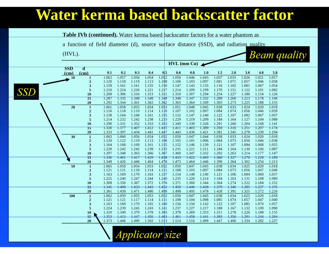
Table IVb (continued). Water kerma based b
Water kerma based( )
a function of field diameter (d), source sur
(HVL).
SSD dSSD d(cm) (cm) 0.1 0.2 0.3 0.4 0.
10 1 1.062 1.057 1.056 1.054 1.052 1.120 1.118 1.119 1.113 1.103 1.159 1.161 1.161 1.155 1.155 1.210 1.224 1.226 1.221 1.21
10 1.269 1.306 1.316 1.313 1.311 287 1 335 1 348 1 348 1 34
SSD15 1.287 1.335 1.348 1.348 1.3420 1.292 1.344 1.361 1.362 1.36
20 1 1.061 1.058 1.055 1.054 1.052 1.116 1.118 1.119 1.114 1.113 1.158 1.164 1.168 1.161 1.155 1.214 1.232 1.242 1.238 1.23
10 1.290 1.331 1.352 1.353 1.3515 1 320 1 377 1 407 1 412 1 4115 1.320 1.377 1.407 1.412 1.4120 1.333 1.397 1.434 1.441 1.44
30 1 1.063 1.060 1.056 1.054 1.052 1.120 1.122 1.119 1.113 1.103 1.164 1.168 1.169 1.161 1.155 1.220 1.242 1.242 1.239 1.23
10 1.297 1.348 1.363 1.366 1.3615 1 330 1 401 1 417 1 429 1 4315 1.330 1.401 1.417 1.429 1.4320 1.348 1.426 1.446 1.464 1.47
50 1 1.065 1.059 1.054 1.053 1.052 1.121 1.121 1.118 1.114 1.113 1.163 1.169 1.170 1.163 1.155 1.225 1.240 1.247 1.244 1.24
10 1.308 1.350 1.367 1.372 1.3715 1 345 1 408 1 433 1 443 1 4515 1.345 1.408 1.433 1.443 1.4520 1.361 1.439 1.471 1.486 1.49
100 1 1.062 1.059 1.055 1.053 1.052 1.121 1.121 1.117 1.114 1.113 1.163 1.169 1.170 1.165 1.165 1.224 1.239 1.245 1.243 1.24
10 1.310 1.349 1.370 1.378 1.3815 1 353 1 413 1 447 1 456 1 4615 1.353 1.413 1.447 1.456 1.4620 1.373 1.446 1.490 1.502 1.51
Applicator s
backscatter factors for a water phantom as
d backscatter factorp
rface distance (SSD), and radiation quality
HVL (mm Cu)Beam quality
.5 0.6 0.8 1.0 1.5 2.0 3.0 4.0 5.052 1.050 1.046 1.043 1.037 1.033 1.026 1.021 1.01708 1.106 1.103 1.097 1.081 1.071 1.057 1.046 1.03850 1.147 1.143 1.135 1.116 1.102 1.081 1.067 1.05417 1.214 1.209 1.199 1.170 1.151 1.122 1.101 1.08211 1.310 1.307 1.294 1.254 1.227 1.186 1.154 1.12648 1 348 1 347 1 332 1 289 1 260 1 213 1 178 1 14648 1.348 1.347 1.332 1.289 1.260 1.213 1.178 1.14662 1.363 1.364 1.349 1.303 1.273 1.225 1.188 1.15553 1.051 1.048 1.045 1.038 1.033 1.024 1.020 1.01810 1.107 1.102 1.097 1.084 1.074 1.056 1.046 1.03955 1.152 1.147 1.140 1.122 1.107 1.082 1.067 1.05733 1.229 1.219 1.209 1.184 1.164 1.127 1.104 1.08853 1.349 1.339 1.326 1.291 1.260 1.204 1.168 1.14115 1 411 1 403 1 389 1 350 1 316 1 251 1 207 1 17415 1.411 1.403 1.389 1.350 1.316 1.251 1.207 1.17447 1.443 1.436 1.421 1.381 1.345 1.278 1.230 1.19452 1.050 1.047 1.044 1.038 1.033 1.024 1.020 1.01808 1.105 1.101 1.096 1.084 1.073 1.056 1.046 1.03855 1.152 1.146 1.139 1.121 1.107 1.084 1.068 1.05535 1.231 1.221 1.211 1.184 1.164 1.130 1.106 1.08767 1.360 1.347 1.332 1.292 1.263 1.214 1.177 1.14738 1 433 1 422 1 405 1 360 1 327 1 270 1 226 1 18938 1.433 1.422 1.405 1.360 1.327 1.270 1.226 1.18978 1.473 1.464 1.446 1.399 1.364 1.302 1.254 1.21352 1.050 1.047 1.045 1.038 1.034 1.025 1.020 1.01811 1.108 1.103 1.097 1.084 1.073 1.056 1.047 1.04057 1.154 1.148 1.140 1.121 1.106 1.084 1.069 1.05740 1.235 1.226 1.214 1.184 1.163 1.131 1.108 1.08976 1.371 1.360 1.344 1.304 1.274 1.222 1.184 1.15252 1 450 1 446 1 428 1 379 1 346 1 285 1 237 1 19552 1.450 1.446 1.428 1.379 1.346 1.285 1.237 1.19599 1.498 1.495 1.478 1.428 1.391 1.325 1.272 1.22652 1.050 1.047 1.045 1.038 1.034 1.025 1.020 1.01811 1.108 1.104 1.098 1.085 1.074 1.057 1.047 1.04060 1.156 1.150 1.142 1.122 1.107 1.085 1.070 1.05741 1.237 1.227 1.217 1.188 1.167 1.132 1.109 1.09083 1.378 1.369 1.353 1.311 1.278 1.226 1.188 1.15563 1 461 1 458 1 441 1 393 1 356 1 291 1 244 1 20463 1.461 1.458 1.441 1.393 1.356 1.291 1.244 1.20413 1.514 1.516 1.499 1.447 1.406 1.334 1.282 1.237
size
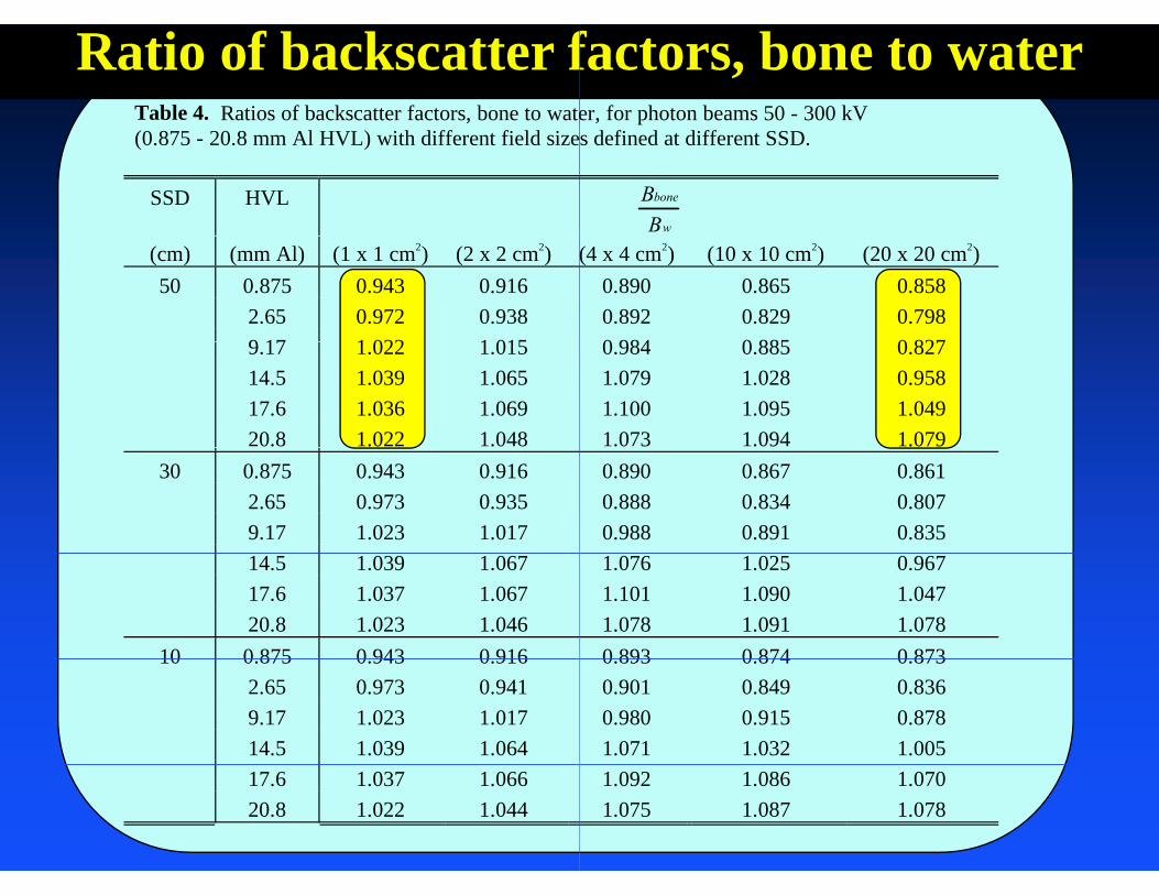
Table 4. Ratios of backscatter factors, bone to wate( l ) i h diff fi ld i
Ratio of backscatter f(0.875 - 20.8 mm Al HVL) with different field size
SSD HVL
(cm) (mm Al) (1 x 1 cm2) (2 x 2 cm2)50 0.875 0.943 0.916
2.65 0.972 0.9389 17 1 022 1 0159.17 1.022 1.01514.5 1.039 1.06517.6 1.036 1.06920.8 1.022 1.048
30 0.875 0.943 0.9162.65 0.973 0.9359.17 1.023 1.01714.5 1.039 1.06717.6 1.037 1.06720.8 1.023 1.046
10 0 875 0 943 0 91610 0.875 0.943 0.9162.65 0.973 0.9419.17 1.023 1.01714.5 1.039 1.06417.6 1.037 1.06620.8 1.022 1.044
er, for photon beams 50 - 300 kVd fi d diff
factors, bone to waters defined at different SSD.
Bbone
Bw
(4 x 4 cm2) (10 x 10 cm2) (20 x 20 cm2)0.890 0.865 0.8580.892 0.829 0.7980 984 0 885 0 8270.984 0.885 0.8271.079 1.028 0.9581.100 1.095 1.0491.073 1.094 1.0790.890 0.867 0.8610.888 0.834 0.8070.988 0.891 0.8351.076 1.025 0.9671.101 1.090 1.0471.078 1.091 1.0780 893 0 874 0 8730.893 0.874 0.8730.901 0.849 0.8360.980 0.915 0.8781.071 1.032 1.0051.092 1.086 1.0701.075 1.087 1.078

Table VII Overall chamber correction factor
Overall chamber Table VII. Overall chamber correction factor
medium-energy x-ray beams. The data applie
field size.
ChamberType
NE2571 CapintecPR06C
PTN30
HVLHVL(mmCu)
0.10 1.008 0.992 1.00.15 1.015 1.000 1.00 20 1 019 1 004 1 00.20 1.019 1.004 1.00.30 1.023 1.008 1.00.40 1.025 1.009 1.00.50 1.025 1.010 1.00.60 1.025 1.010 1.00.60 1.025 1.010 1.00.80 1.024 1.010 1.01.0 1.023 1.010 1.01.5 1.019 1.008 1.02.0 1.016 1.007 1.02.0 1.016 1.007 1.02.5 1.012 1.006 1.03.0 1.009 1.005 1.04.0 1.004 1.003 1.0
rs P for common cylindrical chambers in
correction factorrs PQ,cham for common cylindrical chambers in
es to 2 cm depth in the phantom, and 100 cm2
TW001
ExradinA12
NE2581 NE2611or
NE2561
004 1.002 0.991 0.995013 1.009 1.007 1.007017 1 013 1 017 1 012017 1.013 1.017 1.012021 1.016 1.028 1.017023 1.017 1.033 1.019023 1.017 1.036 1.019023 1.017 1.037 1.019023 1.017 1.037 1.019022 1.017 1.037 1.018021 1.016 1.035 1.017018 1.013 1.028 1.014015 1.011 1.022 1.011015 1.011 1.022 1.011012 1.010 1.017 1.009010 1.008 1.012 1.006006 1.005 1.004 1.003

Chamber Sheath C
Table IV: The Monte Carlo calculated correctiogcm3) sleeves of thickness t Other conditions agcm ) sleeves of thickness t. Other conditions astatistical uncertainties are smaller than 0.001.
B litBeam quality(mm A1) t = 0.5 mm t = 1
1.04 0.990 0.91.04 0.990 0.92.94 0.995 0.94.28 0.996 0.99 20 0 999 0 99.20 0.999 0.913.0 1.000 0.916.6 1.000 0.921 5 1 000 1 021.5 1.000 1.0
Correction Factor
on factors ps for polystyrene ( = 1.06are the same as Table II The 1-are the same as Table II. The 1
f P l tps for Polystyrene1 mm t = 2 mm t = 3 mm
981 0.962 0.943981 0.962 0.943990 0.981 0.972993 0.986 0.979997 0 994 0 992997 0.994 0.992999 0.998 0.997999 0.999 0.999000 1 000 1 000000 1.000 1.000

Consistency betand in-phantand in phant
S l h d b d Select a method based o
Check consistency onlyaccurately
Experimental studies inp(about 1%) using both m
tween the in-air tom methodstom methods
i f ion point of interest
y if PDD can be measured
ndicated consistent results methods at 100 and 300 kV
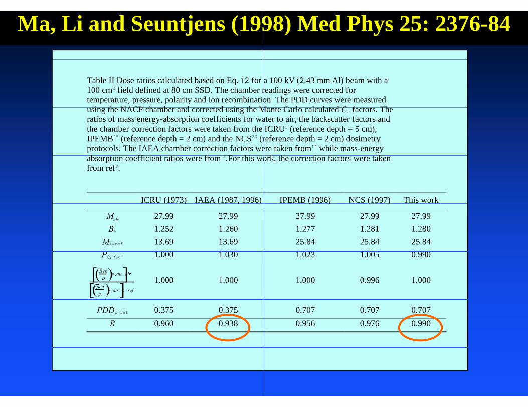
Ma, Li and Seuntjens (199
Table II Dose ratios calculated based on Eq. 12 for a100 cm2 field defined at 80 cm SSD. The chamber rtemperature, pressure, polarity and ion recombinatio
i th NACP h b d t d i th Musing the NACP chamber and corrected using the Mratios of mass energy-absorption coefficients for wathe chamber correction factors were taken from the IPEMB25 (reference depth = 2 cm) and the NCS26 (rprotocols. The IAEA chamber correction factors web i ffi i i f 2 F hiabsorption coefficient ratios were from 2.For this wo
from ref8.
ICRU (1973) IAEA (1987, 1996)( ) ( , )
Mair 27.99 27.99Bw 1.252 1.260
Mz=ref 13.69 13.691 000 1 030PQ,cham 1.000 1.030
en w ,air air
en w,air z ref
1.000 1.000
PDDz=ref 0.375 0.375R 0.960 0.938
98) Med Phys 25: 2376-84
a 100 kV (2.43 mm Al) beam with areadings were corrected foron. The PDD curves were measured
M t C l l l t d C f t ThMonte Carlo calculated Cz factors. Theater to air, the backscatter factors andICRU3 (reference depth = 5 cm),
reference depth = 2 cm) dosimetryere taken from14 while mass-energy
k h i f kork, the correction factors were taken
IPEMB (1996) NCS (1997) This work( ) ( )
27.99 27.99 27.991.277 1.281 1.28025.84 25.84 25.841 023 1 005 0 9901.023 1.005 0.990
1.000 0.996 1.000
0.707 0.707 0.7070.956 0.976 0.990

Guidelines for dGuidelines for dphantom
Determine the surface dose f
h
0zmed, D where
medmed BC w
w BC
The backscatter factor ratios but close to 1.0 for soft tissu
dosimetry in otherdosimetry in other m materials
for other phantom materials from
0zw,medw DC
imed)/(
Vary significantly
airwen )/(
are significant for bone to water ues.

Ratio of BackscatterRatio of Backscatter 1.10
10cmx10cm1.05
10cmx10cm
0.95
1.00
20cmx2
0.90
0.85
Beam Qual0 1 2
0.80
Beam Qual
Factors Bone to WaterFactors, Bone to Water
mm
1cmx1cm20cm
lity (mm Cu)3 4 5
lity (mm Cu)

Relative dosimetr
L t i t i Large uncertainty in
Large uncertainty in Large uncertainty in
Effect of electron conEffect of electron con
Choice of detectors
Choice of phantom m
ry measurement
PDD tPDD measurements
profile measurementsprofile measurements
ntaminationntamination
materials

100
80
90
60
70
30
40
50
10
20
30
0 2 4
distance from centra
09 10 11
Diode
NACP
RK
Farmer
film
al axis / cm
12 13

(300 k(300 kkV beam)kV beam)

(300 kV beam)
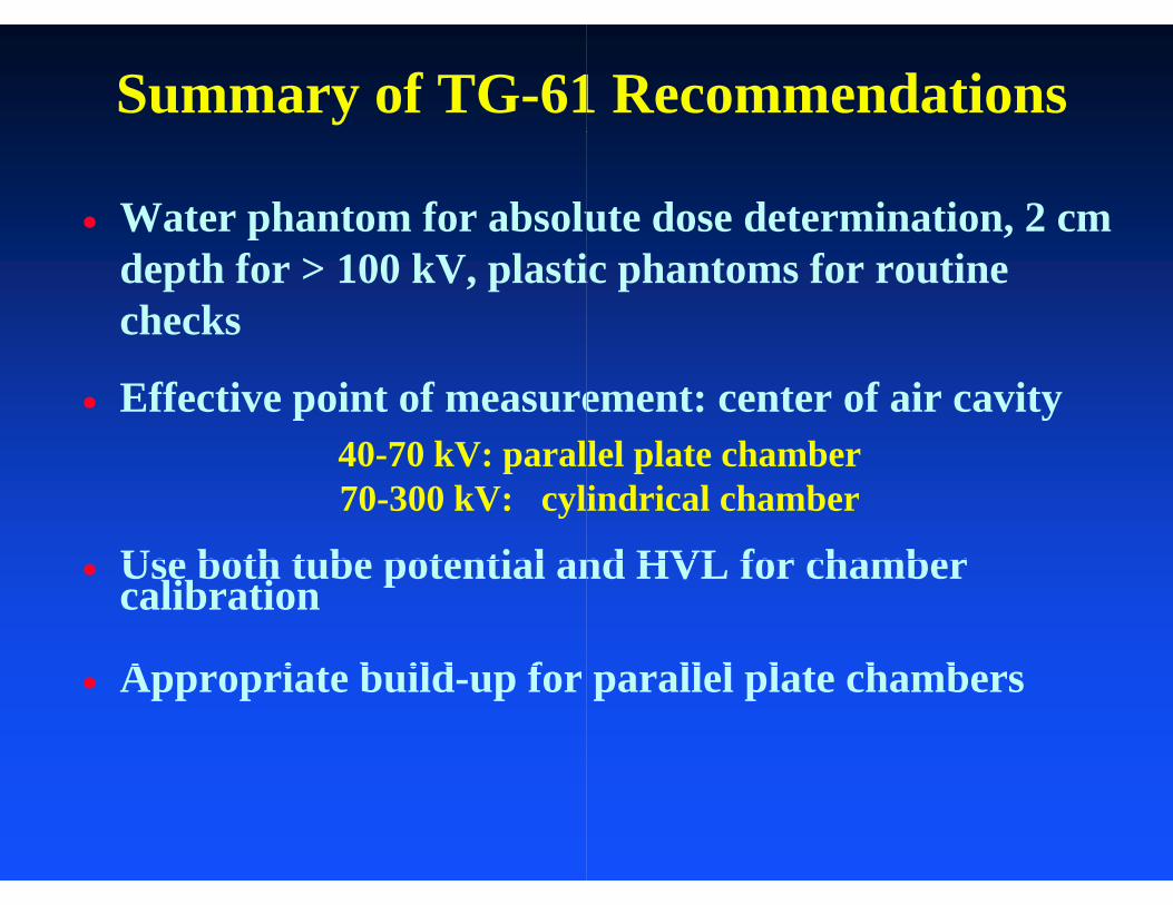
Summary of TG-61
Water phantom for absolupdepth for > 100 kV, plastichecks
Effective point of measure40 70 kV: paral40-70 kV: paral70-300 kV: cyl
Use both tube potential an Use both tube potential ancalibration
A i t b ild f Appropriate build-up for
1 Recommendations
ute dose determination, 2 cm ic phantoms for routine
ement: center of air cavitylel plate chamberlel plate chamberindrical chamber
nd HVL for chambernd HVL for chamber
ll l l t h bparallel plate chambers

Summary of TG-61y
Narrow beam geometry foN g y What method to use depen
of interest (POI)( )40-100 kV : only the in100-300 kV : the in-a
100-300 kV : the in-phan
Inter-compare chamber fo
Use HVL as beam quality scorrection factor (tabular dcorrection factor (tabular d
Quality assurance (daily m Quality assurance (daily, m
1 Recommendations
r HVL determinationVnding on beam quality and point
n-air method should be usedir method if POI on surfacentom method if POI at a depth
or correction/conversion factors
specifier for conversion and data preferred)data preferred)
monthly annually)monthly, annually)
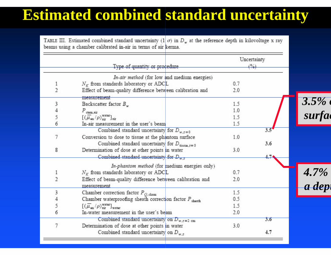
Estimated combined standard uncertainty
3 5%3.5% osurfac
4.7% a depta dept

C lConclu Exposure/kerma based
Backscatter method forbenergy x-ray beams
Complete data set avai Complete data set avaiand Psheath
Consistent results usin
iusionsd dosimetry procedures
r both low- and medium-
ilable for en/ B PQ chamilable for en/, B, PQ,cham
g both formalisms

Questions for kV
1. Does a Farmer chambekV x-ray beams?kV x-ray beams?
2. Does the Bragg-Gray cFarmer chamber for kV
3 Is the difference betwe3. Is the difference betwekV x-ray beams?A i fill d i i ti4. Are air-filled ionizationdetectors” or “electron
V x-ray dosimetry
er have enough buildup for
cavity theory apply to a V x-ray beams?en K l and K significant foren Kcol and K significant for
h b d “ h tn chambers used as “photon detectors” for kV beams?

Answ
1. Yes, electron rang2. No, significant ene
electrons generatedelectrons generated3. No, g < 0.1%4. “Photon detectors”
wers:
es < 0.5mm of waterergy deposition from d in the air cavityd in the air cavity
”
Top Related