


Languages
Pages
Legal

®
July 15th , 2013 Document-No: DB_PCapØ1-0301_en V0.6
SUNSTAR传感与控制 http://www.sensor-ic.com/ TEL:0755-83376549 FAX:0755-83376182 E-MAIL:[email protected]
SUNSTAR自动化 http://www.sensor-ic.com/ TEL: 0755-83376489 FAX:0755-83376182 E-MAIL:[email protected]

® PCapØ1Ax-0301
acam messelectronic gmbh - Friedrich-List-Str.4 - 76297 Stutensee - Germany - www.acam.de
Publ ished by acam-messelectronic gmbh ©acam-messelectronic gmbh 2013
Legal note The present manual (data sheet and guide) is still under development, which may result in corrections, modifications or additions. acam cannot be held liable for any of its contents, neither for accuracy, nor for completeness. The compiled information is believed correct,
though some errors and omissions are likely. We welcome any notification, which will be integrated in succeeding releases.
The acam recommendations are believed useful, the firmware proposals and the schematics operable, nevertheless it is of the customer‘s sole responsibility to modify, test
and validate them before setting up any production process. acam products are not designed for use in medical, nuclear, military, aircraft, spacecraft
or lifesupport devices. Nor are they suitable for applications where failure may provoke injury to people or heavy material damage. acam declines any liability with respect to such
non-intended use, which remains under the customer‘s sole responsibility and risk. Military, spatial and nuclear use subject to German export regulations.
acam do not warrant, and it is not implied that the information and/or practice presented here is free from patent, copyright or similar protection. All registered names and
trademarks are mentioned for reference only and remain the property of their respective owners. The acam logo and the PicoCap logo are registered trademarks of acam-
messelectronic gmbh, Germany.
Support / Contact For a complete listing of Direct Sales, Distributor and Sales Representative contacts, visit
the acam web site at:
http://www.acam.de/sales/distributors/
For technical support you can contact the acam support team in the headquarters in Germany or the Distributor in your country. The contact details of acam in Germany are:
[email protected] or by phone +49-7244-74190.
SUNSTAR传感与控制 http://www.sensor-ic.com/ TEL:0755-83376549 FAX:0755-83376182 E-MAIL:[email protected]
SUNSTAR自动化 http://www.sensor-ic.com/ TEL: 0755-83376489 FAX:0755-83376182 E-MAIL:[email protected]
PCapØ1Ax-0301
acam messelectronic gmbh - Friedrich-List-Str.4 - 76297 Stutensee - Germany - www.acam.de 1
Content
1 System Overview ........................................................................................ 1-1
1.1 Features ............................................................................................. 1-1
1.2 Applications ........................................................................................ 1-2
1.3 Block diagram ..................................................................................... 1-3
1.4 Part Numbers ..................................................................................... 1-3
2 Characteristics & Specifications ................................................................... 2-1
2.1 Electrical Characteristics ....................................................................... 2-2
2.2 CDC Precision ..................................................................................... 2-4
2.3 Internal RC-Oscillator ............................................................................ 2-9
2.4 RDC Precision ................................................................................... 2-11
2.5 Power Consumption ............................................................................ 2-12
2.6 Package Information ........................................................................... 2-13
3 Converter Frontend .................................................................................... 3-1
3.1 CDC Measuring Principle ....................................................................... 3-2
3.2 Important CDC Parameters .................................................................... 3-2
3.3 CDC External Circuitry ........................................................................... 3-4
3.4 Connecting the Capacitive Sensors .......................................................... 3-5
3.5 Selecting the Discharge Resistor ............................................................. 3-6
3.6 Compensation Measurement .................................................................. 3-7
3.7 RDC Temperature Measurement ............................................................. 3-8
4 Interfaces (Serial And Pulse-Density) .............................................................. 4-1
4.1 Serial Interfaces................................................................................... 4-2
4.2 PDM/PWM and GPIO ........................................................................... 4-7
5 Write & Read Registers .............................................................................. 5-1
5.1 Configuration & Parameter Registers ....................................................... 5-2
5.2 Explanations to Configuration Registers .................................................. 5-15
5.3 Read Registers .................................................................................. 5-19
6 DSP, Memory & Firmware ........................................................................... 6-1
6.1 DSP Management and Programming ........................................................ 6-2
6.2 Memory Map ....................................................................................... 6-4
6.3 Memory Management ........................................................................... 6-4
6.4 OTP Firmware programming ................................................................... 6-5
6.5 Getting Started .................................................................................... 6-6
7 Miscellaneous ........................................................................................... 7-1
7.1 Bug Report ......................................................................................... 7-2
7.2 Document History ................................................................................ 7-5
SUNSTAR传感与控制 http://www.sensor-ic.com/ TEL:0755-83376549 FAX:0755-83376182 E-MAIL:[email protected]
SUNSTAR自动化 http://www.sensor-ic.com/ TEL: 0755-83376489 FAX:0755-83376182 E-MAIL:[email protected]

® PCapØ1Ax-0301
2 acam messelectronic gmbh - Friedrich-List-Str.4 - 76297 Stutensee - Germany - www.acam.de
SUNSTAR传感与控制 http://www.sensor-ic.com/ TEL:0755-83376549 FAX:0755-83376182 E-MAIL:[email protected]
SUNSTAR自动化 http://www.sensor-ic.com/ TEL: 0755-83376489 FAX:0755-83376182 E-MAIL:[email protected]

PCapØ1Ax-0301
acam messelectronic gmbh - Friedrich-List-Str.4 - 76297 Stutensee - Germany - www.acam.de 1-1
1 System Overview
PCapØ1 is a dedicated Capacitance-to-Digital Conversion Digital Signal Processor. Its front
end is based on acam‘s patented ® principle. This conversion principle offers high
resolution at conversion times as short as 2 µs. Customers benefit from outstanding
flexibility for optimizing power consumption, resolution and speed.
The PCap01A can be used for grounded single and differential sensors as well as for
floating single and differential sensors. With grounded capacitors the stray capacitance
inside the chip will be compensated. With floating capacitors, further to the internal stray
capacitance, the external stray capacitances as well get compensated. Additionally, the
temperature can be measured by means of internal thermistors or external ones (platinum
or others). Before loading some firmware to it, the chip is not completely operable. Data
will end up in ALU instead of being transferred to processor and/or output. Under this
circumstance, we chose to write a combined data sheet covering the hardware aspects as
well as handling a very basic firmware called 03.01.xx; this basic or “standard“ firmware
calculates the capacitance and resistance ratios and transfers them to the data output
ports, still without doing such further possible processing like filtering and linearization. It
is provided free of charge with the chip, yet, it needs to be loaded via SPI or I2C.
For clarity, those aspects that are standard-firmware related have been marked with a
blue stripe in the margin. User-written firmware may behave differently here.
1.1 Features
Digital measuring principle in CMOS technology
Up to 8 capacitances in grounded mode
Up to 4 capacitances in floating mode (potential- free and with zero bias voltage)
Compensation of internal (grounded) and external parasitic capacities (floating)
High resolution: up to 6 aF at 5 Hz and 10 pF base capacitance, or 17 bit
resolution at 5 Hz with 100 pF base capacitance and 10 pF excitation
High measurement rate: up to 500 kHz
Extremely low current consumption possible:
Down to 4 µA at 3 Hz with 13.4 bit resolution
High stability with temperature, low offset drift (down to 30 aF per Kelvin), low gain
drift when all compensation options are activated.
Fir
mw
are R
ela
ted
SUNSTAR传感与控制 http://www.sensor-ic.com/ TEL:0755-83376549 FAX:0755-83376182 E-MAIL:[email protected]
SUNSTAR自动化 http://www.sensor-ic.com/ TEL: 0755-83376489 FAX:0755-83376182 E-MAIL:[email protected]

® PCapØ1Ax-0301
1-2 acam messelectronic gmbh - Friedrich-List-Str.4 - 76297 Stutensee - Germany - www.acam.de
Dedicated ports for precision temperature measurement (with Pt1000 sensors,
the resolution is 0.005 K)
Serial interfaces (SPI or I2C compatible)
Self-boot capability
Single power supply (2.1 to 3.6 V)
No need for a clock
RISC processor core using Harvard architecture:
48 x 48 bit RAM Data
4k x 8 bit volatile program memory for high-speed operation (40 to 100
MHz)
4k x 8 bit non-volatile (OTP) program memory for normal speed operation
(up to 40 MHz)
1.2 Applications
Humidity sensors
Position sensors
Pressure sensors
Force sensors
Acceleration sensors
Inclination sensors
Tilt sensors
Angle sensors
Wireless applications
Level sensors
Microphones
MEMS sensors
SUNSTAR传感与控制 http://www.sensor-ic.com/ TEL:0755-83376549 FAX:0755-83376182 E-MAIL:[email protected]
SUNSTAR自动化 http://www.sensor-ic.com/ TEL: 0755-83376489 FAX:0755-83376182 E-MAIL:[email protected]
PCapØ1Ax-0301
acam messelectronic gmbh - Friedrich-List-Str.4 - 76297 Stutensee - Germany - www.acam.de 1-3
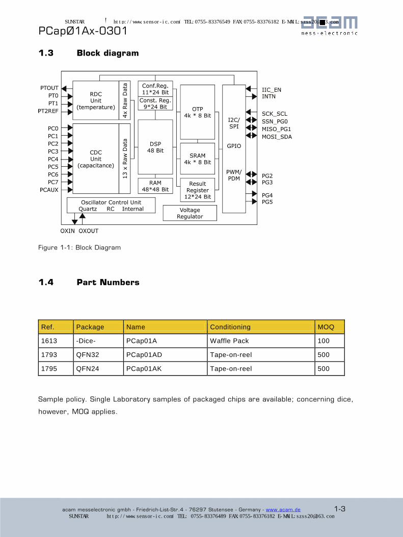
1.3 Block diagram
Figure 1-1: Block Diagram
1.4 Part Numbers
Ref. Package Name Conditioning MOQ
1613 -Dice- PCap01A Waffle Pack 100
1793 QFN32 PCap01AD Tape-on-reel 500
1795 QFN24 PCap01AK Tape-on-reel 500
Sample policy. Single Laboratory samples of packaged chips are available; concerning dice,
however, MOQ applies.
SUNSTAR传感与控制 http://www.sensor-ic.com/ TEL:0755-83376549 FAX:0755-83376182 E-MAIL:[email protected]
SUNSTAR自动化 http://www.sensor-ic.com/ TEL: 0755-83376489 FAX:0755-83376182 E-MAIL:[email protected]

® PCapØ1Ax-0301
1-4 acam messelectronic gmbh - Friedrich-List-Str.4 - 76297 Stutensee - Germany - www.acam.de
SUNSTAR传感与控制 http://www.sensor-ic.com/ TEL:0755-83376549 FAX:0755-83376182 E-MAIL:[email protected]
SUNSTAR自动化 http://www.sensor-ic.com/ TEL: 0755-83376489 FAX:0755-83376182 E-MAIL:[email protected]
PCapØ1Ax-0301
acam messelectronic gmbh - Friedrich-List-Str.4 - 76297 Stutensee - Germany - www.acam.de 2-1
2 Characteristics & Specifications
2.1 Electrical Characteristics ....................................................................... 2-2
2.1.1 Absolute Maximum Ratings .............................................................. 2-2
2.1.2 Recommended Operating Conditions .................................................. 2-3
2.2 CDC Precision ..................................................................................... 2-4
2.2.1 RMS Noise and Resolution vs. Output Data Rate .................................. 2-4
2.2.2 RMS Noise vs. Supply Voltage ........................................................... 2-7
2.2.3 Voltage-Dependent Offset and Gain Error (PSRR) .................................. 2-7
2.2.4 Temperature-Dependent Offset and Gain Error ..................................... 2-8
2.3 Internal RC-Oscillator ............................................................................ 2-9
2.4 RDC Precision ................................................................................... 2-11
2.5 Power Consumption ............................................................................ 2-12
2.6 Package Information ........................................................................... 2-13
2.6.1 Dice - Pad Layout ......................................................................... 2-13
2.6.2 QFN Packages ............................................................................. 2-14
2.6.3 Pin-Out QFN32 and QFN24 Versions ................................................ 2-15
2.6.4 Pin/Pad Assignment ..................................................................... 2-16
SUNSTAR传感与控制 http://www.sensor-ic.com/ TEL:0755-83376549 FAX:0755-83376182 E-MAIL:[email protected]
SUNSTAR自动化 http://www.sensor-ic.com/ TEL: 0755-83376489 FAX:0755-83376182 E-MAIL:[email protected]
® PCapØ1Ax-0301
2-2 acam messelectronic gmbh - Friedrich-List-Str.4 - 76297 Stutensee - Germany - www.acam.de
2.1 Electrical Characteristics
2.1.1 Absolute Maximum Ratings
Supply voltage VDD-to-GND - 0.3 to 4.0 V
Storage temperature Tstg - 55 to 150 °C
ESD rating (HBM), each pin > 2 kV
Junction temperature (Tj) max. 125 °C
OTP Data Retention Period 10 years at 95 °C temperature
SUNSTAR传感与控制 http://www.sensor-ic.com/ TEL:0755-83376549 FAX:0755-83376182 E-MAIL:[email protected]
SUNSTAR自动化 http://www.sensor-ic.com/ TEL: 0755-83376489 FAX:0755-83376182 E-MAIL:[email protected]
PCapØ1Ax-0301
acam messelectronic gmbh - Friedrich-List-Str.4 - 76297 Stutensee - Germany - www.acam.de 2-3
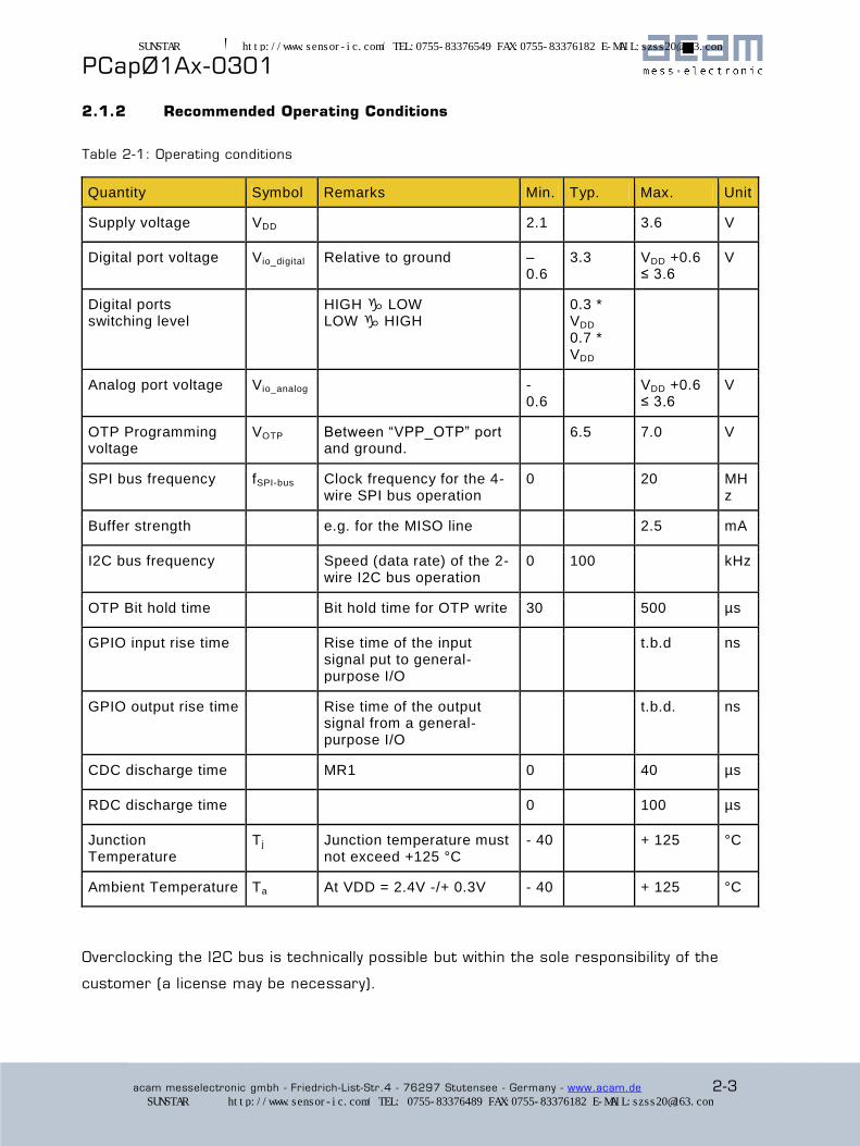
2.1.2 Recommended Operating Conditions
Table 2-1: Operating conditions
Quantity Symbol Remarks Min. Typ. Max. Unit
Supply voltage VDD 2.1 3.6 V
Digital port voltage Vio_digital Relative to ground – 0.6
3.3 VDD +0.6 ≤ 3.6
V
Digital ports switching level
HIGH LOW LOW HIGH
0.3 * VDD
0.7 * VDD
Analog port voltage Vio_analog - 0.6
VDD +0.6 ≤ 3.6
V
OTP Programming voltage
VOTP Between “VPP_OTP” port and ground.
6.5 7.0 V
SPI bus frequency fSPI-bus Clock frequency for the 4-wire SPI bus operation
0 20 MHz
Buffer strength e.g. for the MISO line 2.5 mA
I2C bus frequency Speed (data rate) of the 2-wire I2C bus operation
0 100 kHz
OTP Bit hold time Bit hold time for OTP write 30 500 µs
GPIO input rise time Rise time of the input signal put to general-purpose I/O
t.b.d ns
GPIO output rise time Rise time of the output signal from a general-purpose I/O
t.b.d. ns
CDC discharge time MR1 0 40 µs
RDC discharge time 0 100 µs
Junction Temperature
T j Junction temperature must not exceed +125 °C
- 40 + 125 °C
Ambient Temperature Ta At VDD = 2.4V -/+ 0.3V - 40 + 125 °C
Overclocking the I2C bus is technically possible but within the sole responsibility of the
customer (a license may be necessary).
SUNSTAR传感与控制 http://www.sensor-ic.com/ TEL:0755-83376549 FAX:0755-83376182 E-MAIL:[email protected]
SUNSTAR自动化 http://www.sensor-ic.com/ TEL: 0755-83376489 FAX:0755-83376182 E-MAIL:[email protected]
® PCapØ1Ax-0301
2-4 acam messelectronic gmbh - Friedrich-List-Str.4 - 76297 Stutensee - Germany - www.acam.de
2.2 CDC Precision
2.2.1 RMS Noise and Resolution vs. Output Data Rate
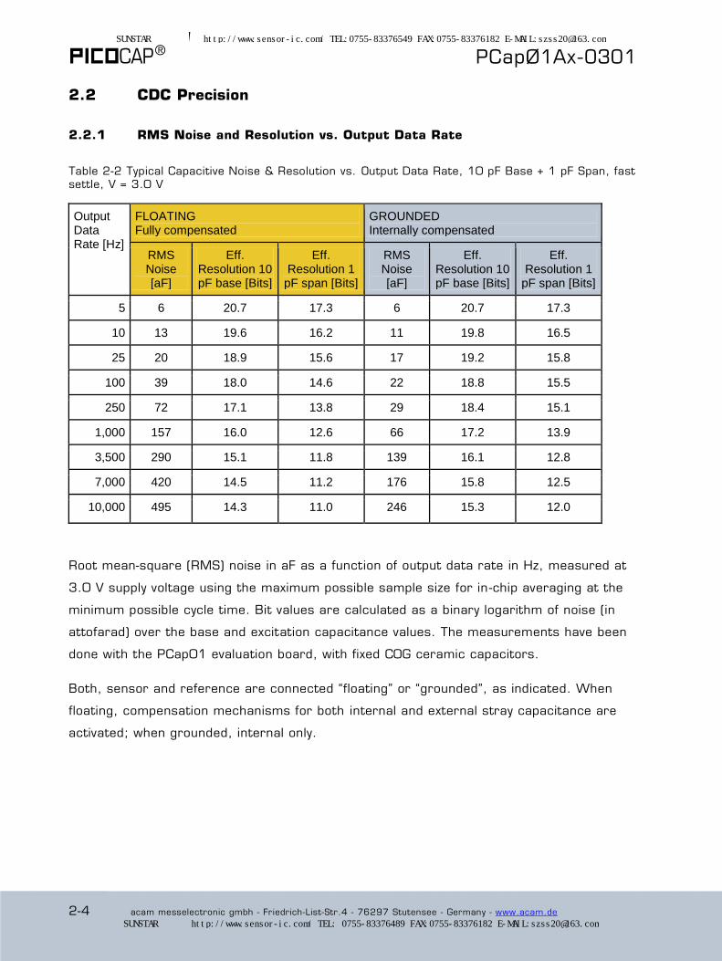
Table 2-2 Typical Capacitive Noise & Resolution vs. Output Data Rate, 10 pF Base + 1 pF Span, fast settle, V = 3.0 V
Output Data Rate [Hz]
FLOATING Fully compensated
GROUNDED Internally compensated
RMS Noise [aF]
Eff. Resolution 10 pF base [Bits]
Eff. Resolution 1
pF span [Bits]
RMS Noise [aF]
Eff. Resolution 10 pF base [Bits]
Eff. Resolution 1
pF span [Bits]
5 6 20.7 17.3 6 20.7 17.3
10 13 19.6 16.2 11 19.8 16.5
25 20 18.9 15.6 17 19.2 15.8
100 39 18.0 14.6 22 18.8 15.5
250 72 17.1 13.8 29 18.4 15.1
1,000 157 16.0 12.6 66 17.2 13.9
3,500 290 15.1 11.8 139 16.1 12.8
7,000 420 14.5 11.2 176 15.8 12.5
10,000 495 14.3 11.0 246 15.3 12.0
Root mean-square (RMS) noise in aF as a function of output data rate in Hz, measured at
3.0 V supply voltage using the maximum possible sample size for in -chip averaging at the
minimum possible cycle time. Bit values are calculated as a binary logarithm of noise (in
attofarad) over the base and excitation capacitance values. The measurements have been
done with the PCap01 evaluation board, with fixed C0G ceramic capacitors.
Both, sensor and reference are connected “floating” or “grounded”, as indicated. When
floating, compensation mechanisms for both internal and external stray capacitance are
activated; when grounded, internal only.
SUNSTAR传感与控制 http://www.sensor-ic.com/ TEL:0755-83376549 FAX:0755-83376182 E-MAIL:[email protected]
SUNSTAR自动化 http://www.sensor-ic.com/ TEL: 0755-83376489 FAX:0755-83376182 E-MAIL:[email protected]

PCapØ1Ax-0301
acam messelectronic gmbh - Friedrich-List-Str.4 - 76297 Stutensee - Germany - www.acam.de 2-5
Table 2-3 Typical Capacitive Noise & Resolution vs. Output Data Rate, 33 pF Base + 3.3 pF Span, fast settle, V = 3.0 V
Output Data Rate [Hz]
FLOATING Fully compensated
GROUNDED Internally compensated
RMS Noise [aF]
Eff. Resolution 33 pF base [Bits]
Eff. Resolution 3.3 pF span
[Bits]
RMS Noise [aF]
Eff. Resolution 33 pF base [Bits]
Eff. Resolution 3.3 pF span
[Bits]
5 18 20.8 17.5 12 21.4 18.1
10 26 20.3 17.0 16 21.0 17.7
25 42 19.6 16.3 28 20.2 16.8
100 79 18.7 15.4 50 19.3 16.0
250 134 17.9 14.6 75 18.7 15.4
1,000 321 16.6 13.3 176 17.5 14.2
3,500 546 15.9 12.6 325 16.6 13.3
7,000 756 15.4 12.1 508 16.0 12.7
10,000 1119 14.8 11.5 742 15.4 12.1
Table 2-4 Typical Capacitive Noise & Resolution vs. Output Data Rate, 100 pF Base + 10 pF Span, fast settle, V = 3.0 V
Output Data Rate [Hz]
FLOATING Fully compensated
GROUNDED Internally compensated
RMS Noise [aF]
Eff. Resolution
100 pF base [Bits]
Eff. Resolution 10 pF span [Bits]
RMS Noise [aF]
Eff. Resolution
100 pF base [Bits]
Eff. Resolution 10pF span
[Bits]
5 71 20.4 17.1 106 19.8 16.5
10 91 20.1 16.7 133 19.5 16.2
25 185 19.0 15.7 226 18.8 15.4
100 321 18.2 14.9 350 18.1 14.8
250 543 17.5 14.2 480 17.7 14.3
1,000 1044 16.5 13.2 987 16.6 13.3
3,500 3320 14.9 11.6 1965 15.6 12.3
7,000 4226 14.5 11.2 3675 14.7 11.4
SUNSTAR传感与控制 http://www.sensor-ic.com/ TEL:0755-83376549 FAX:0755-83376182 E-MAIL:[email protected]
SUNSTAR自动化 http://www.sensor-ic.com/ TEL: 0755-83376489 FAX:0755-83376182 E-MAIL:[email protected]

® PCapØ1Ax-0301
2-6 acam messelectronic gmbh - Friedrich-List-Str.4 - 76297 Stutensee - Germany - www.acam.de
Figure 2-1 Typical Capacitive Noise vs. Output
Data Rate, with 10 pF Base Capacitance, V = 3.0 V
Figure 2-2 Typical Capacitive Noise vs. Output
Data Rate, with 33 pF Base Capacitance, V = 3.0 V
Figure 2-3 Typical Capacitive Noise vs. Output Data Rate, with 100 pF Base Capacitance, V =
3.0 V
SUNSTAR传感与控制 http://www.sensor-ic.com/ TEL:0755-83376549 FAX:0755-83376182 E-MAIL:[email protected]
SUNSTAR自动化 http://www.sensor-ic.com/ TEL: 0755-83376489 FAX:0755-83376182 E-MAIL:[email protected]
PCapØ1Ax-0301
acam messelectronic gmbh - Friedrich-List-Str.4 - 76297 Stutensee - Germany - www.acam.de 2-7
2.2.2 RMS Noise vs. Supply Voltage
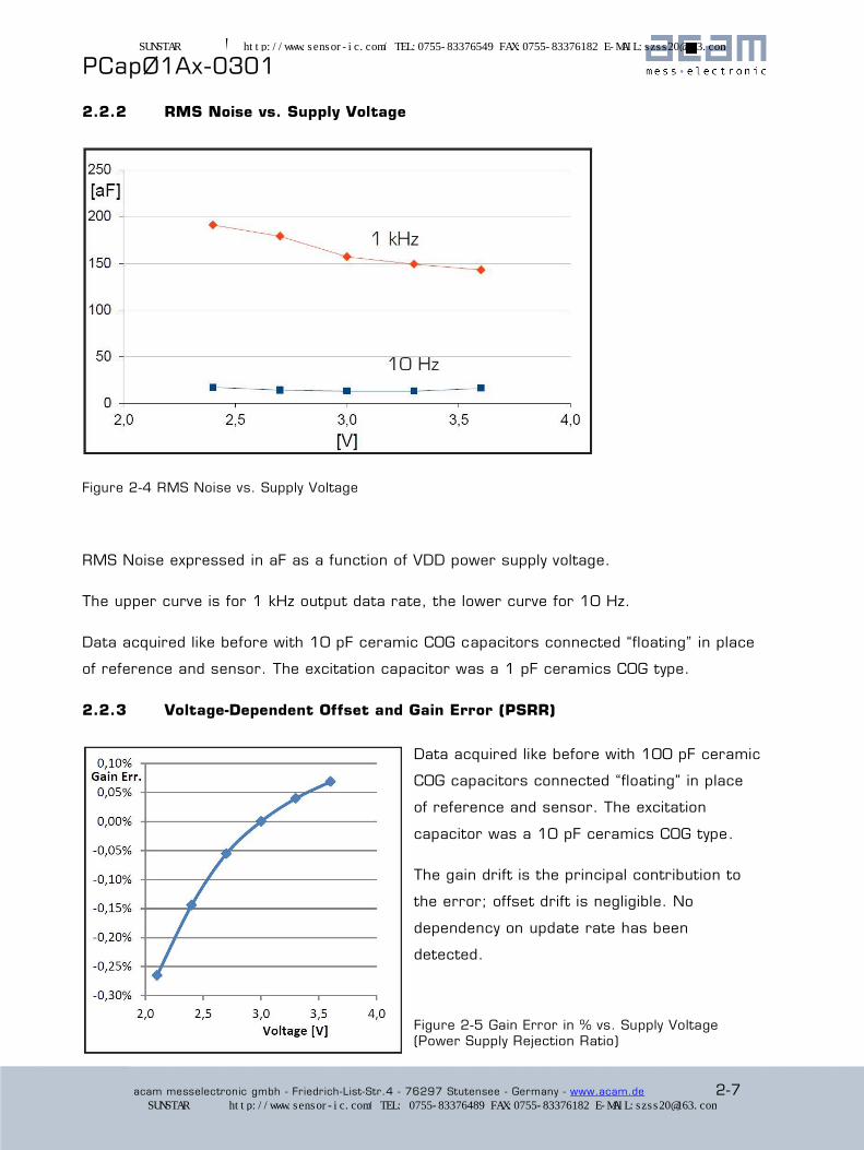
Figure 2-4 RMS Noise vs. Supply Voltage
RMS Noise expressed in aF as a function of VDD power supply voltage.
The upper curve is for 1 kHz output data rate, the lower curve for 10 Hz.
Data acquired like before with 10 pF ceramic C0G capacitors connected “floating” in place
of reference and sensor. The excitation capacitor was a 1 pF ceramics C0G type.
2.2.3 Voltage-Dependent Offset and Gain Error (PSRR)
Data acquired like before with 100 pF ceramic
C0G capacitors connected “floating” in place
of reference and sensor. The excitation
capacitor was a 10 pF ceramics C0G type.
The gain drift is the principal contribution to
the error; offset drift is negligible. No
dependency on update rate has been
detected.
Figure 2-5 Gain Error in % vs. Supply Voltage (Power Supply Rejection Ratio)
SUNSTAR传感与控制 http://www.sensor-ic.com/ TEL:0755-83376549 FAX:0755-83376182 E-MAIL:[email protected]
SUNSTAR自动化 http://www.sensor-ic.com/ TEL: 0755-83376489 FAX:0755-83376182 E-MAIL:[email protected]
® PCapØ1Ax-0301
2-8 acam messelectronic gmbh - Friedrich-List-Str.4 - 76297 Stutensee - Germany - www.acam.de
At present, power-supply rejection ratio is poor, so the component needs well-filtered,
stable supply voltages. Linear regulators will be indicated in most cases. The data
presented here have been acquired in such conditions.
Any switching regulator in the supply line must be separated from the chip through a linear
voltage regulator, combined with some purposefully designed RC filter. Any drift and noise
in the supply line add error and noise to the output.
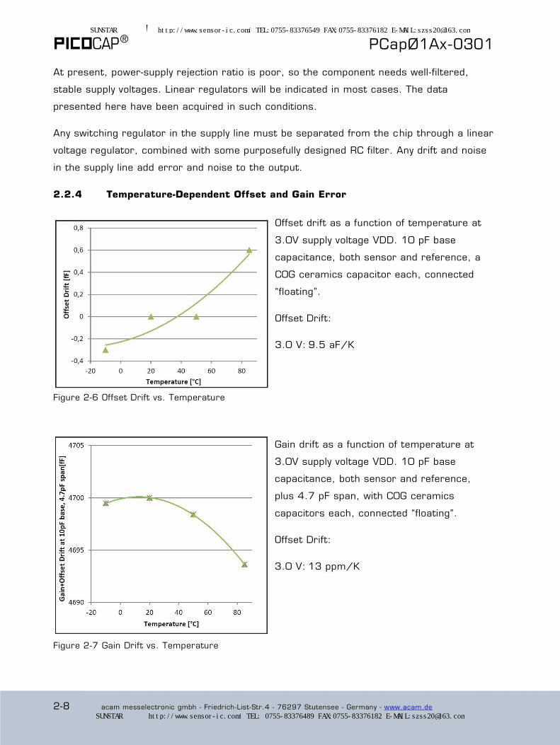
2.2.4 Temperature-Dependent Offset and Gain Error
Offset drift as a function of temperature at
3.0V supply voltage VDD. 10 pF base
capacitance, both sensor and reference, a
C0G ceramics capacitor each, connected
“floating”.
Offset Drift:
3.0 V: 9.5 aF/K
Figure 2-6 Offset Drift vs. Temperature
Gain drift as a function of temperature at
3.0V supply voltage VDD. 10 pF base
capacitance, both sensor and reference,
plus 4.7 pF span, with C0G ceramics
capacitors each, connected “floating”.
Offset Drift:
3.0 V: 13 ppm/K
Figure 2-7 Gain Drift vs. Temperature
SUNSTAR传感与控制 http://www.sensor-ic.com/ TEL:0755-83376549 FAX:0755-83376182 E-MAIL:[email protected]
SUNSTAR自动化 http://www.sensor-ic.com/ TEL: 0755-83376489 FAX:0755-83376182 E-MAIL:[email protected]
PCapØ1Ax-0301
acam messelectronic gmbh - Friedrich-List-Str.4 - 76297 Stutensee - Germany - www.acam.de 2-9
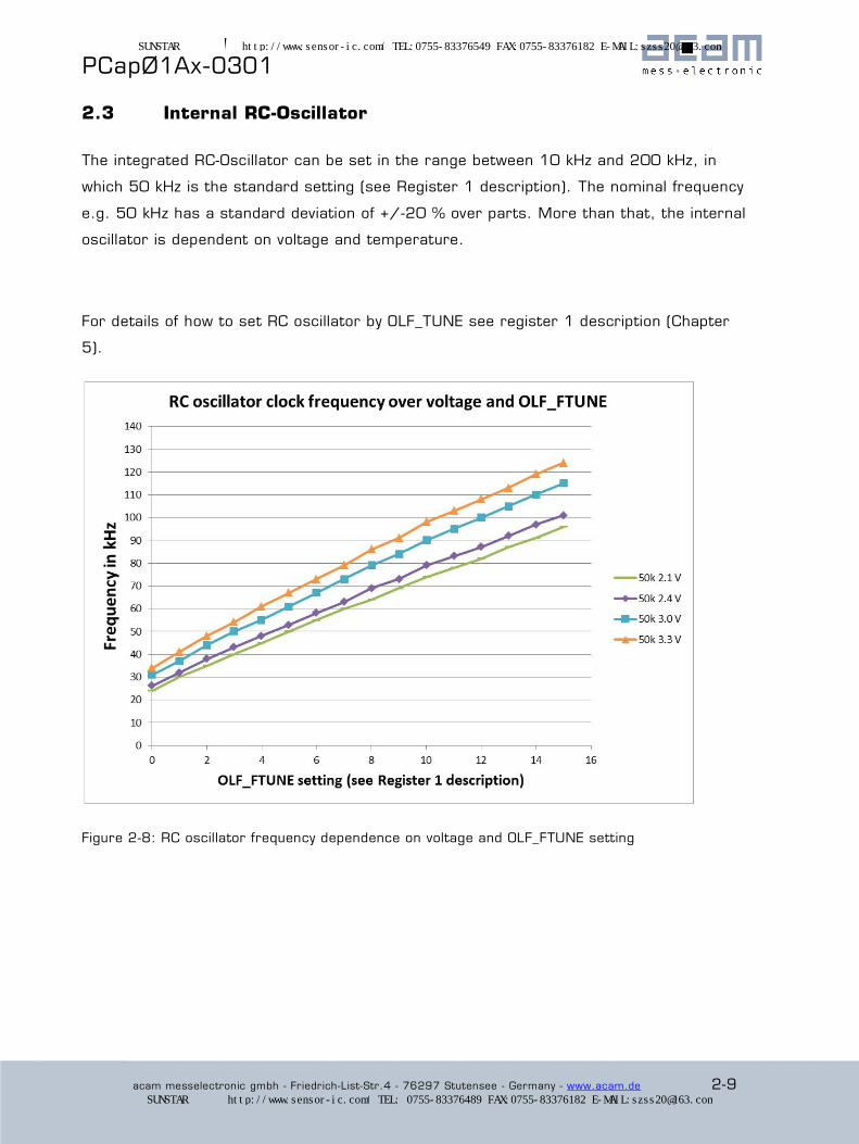
2.3 Internal RC-Oscillator
The integrated RC-Oscillator can be set in the range between 10 kHz and 200 kHz, in
which 50 kHz is the standard setting (see Register 1 description). The nominal frequency
e.g. 50 kHz has a standard deviation of +/-20 % over parts. More than that, the internal
oscillator is dependent on voltage and temperature.
For details of how to set RC oscillator by OLF_TUNE see register 1 description (Chapter
5).
Figure 2-8: RC oscillator frequency dependence on voltage and OLF_FTUNE setting
SUNSTAR传感与控制 http://www.sensor-ic.com/ TEL:0755-83376549 FAX:0755-83376182 E-MAIL:[email protected]
SUNSTAR自动化 http://www.sensor-ic.com/ TEL: 0755-83376489 FAX:0755-83376182 E-MAIL:[email protected]

® PCapØ1Ax-0301
2-10 acam messelectronic gmbh - Friedrich-List-Str.4 - 76297 Stutensee - Germany - www.acam.de
Figure 2-9: RC oscillator frequency dependence on temperature and OLF_FTUNE setting 0-15
Figure 2-10: RC oscillator frequency dependence on temperature and OLF_FTUNE setting 0-2
SUNSTAR传感与控制 http://www.sensor-ic.com/ TEL:0755-83376549 FAX:0755-83376182 E-MAIL:[email protected]
SUNSTAR自动化 http://www.sensor-ic.com/ TEL: 0755-83376489 FAX:0755-83376182 E-MAIL:[email protected]
PCapØ1Ax-0301
acam messelectronic gmbh - Friedrich-List-Str.4 - 76297 Stutensee - Germany - www.acam.de 2-11
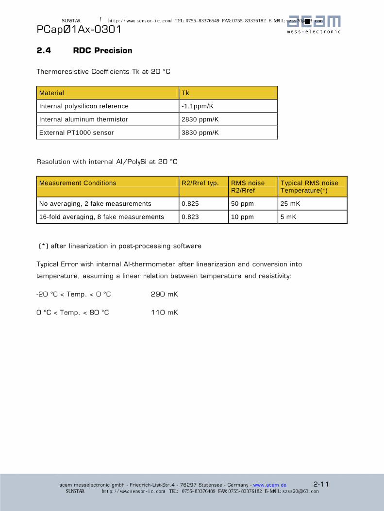
2.4 RDC Precision
Thermoresistive Coefficients Tk at 20 °C
Material Tk
Internal polysilicon reference -1.1ppm/K
Internal aluminum thermistor 2830 ppm/K
External PT1000 sensor 3830 ppm/K
Resolution with internal Al/PolySi at 20 °C
Measurement Conditions R2/Rref typ. RMS noise R2/Rref
Typical RMS noise Temperature(*)
No averaging, 2 fake measurements 0.825 50 ppm 25 mK
16-fold averaging, 8 fake measurements 0.823 10 ppm 5 mK
(*) after linearization in post-processing software
Typical Error with internal Al-thermometer after linearization and conversion into
temperature, assuming a linear relation between temperature and resistivity:
-20 °C < Temp. < 0 °C 290 mK
0 °C < Temp. < 80 °C 110 mK
SUNSTAR传感与控制 http://www.sensor-ic.com/ TEL:0755-83376549 FAX:0755-83376182 E-MAIL:[email protected]
SUNSTAR自动化 http://www.sensor-ic.com/ TEL: 0755-83376489 FAX:0755-83376182 E-MAIL:[email protected]
® PCapØ1Ax-0301
2-12 acam messelectronic gmbh - Friedrich-List-Str.4 - 76297 Stutensee - Germany - www.acam.de
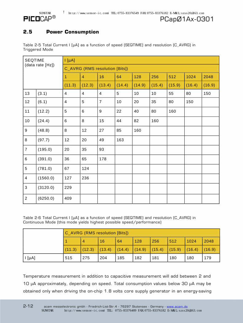
2.5 Power Consumption
Table 2-5 Total Current I [µA] as a function of speed (SEQTIME) and resolution (C_AVRG) in
Triggered Mode
SEQTIME (data rate [Hz])
I [µA]
C_AVRG (RMS resolution [Bits])
1 4 16 64 128 256 512 1024 2048
(11.3) (12.3) (13.4) (14.4) (14.9) (15.4) (15.9) (16.4) (16.9)
13 (3.1) 4 4 4 5 10 10 55 80 150
12 (6.1) 4 5 7 10 20 35 80 150
11 (12.2) 5 6 9 22 40 80 160
10 (24.4) 6 8 15 44 82 160
9 (48.8) 8 12 27 85 160
8 (97.7) 12 20 49 163
7 (195.0) 20 35 93
6 (391.0) 36 65 178
5 (781.0) 67 124
4 (1560.0) 127 236
3 (3120.0) 229
2 (6250.0) 409
Table 2-6 Total Current I [µA] as a function of speed (SEQTIME) and resolution (C_AVRG) in Continuous Mode (this mode yields highest possible speed/performance)
C_AVRG (RMS resolution [Bits])
1 4 16 64 128 256 512 1024 2048
(11.3) (12.3) (13.4) (14.4) (14.9) (15.4) (15.9) (16.4) (16.9)
I [µA] 515 275 204 185 182 181 180 180 179
Temperature measurement in addition to capacitive measurement will add between 2 and
10 µA approximately, depending on speed. Total consumption values below 30 µA may be
obtained only when driving the on-chip 1.8 volts core supply generator in an energy-saving
SUNSTAR传感与控制 http://www.sensor-ic.com/ TEL:0755-83376549 FAX:0755-83376182 E-MAIL:[email protected]
SUNSTAR自动化 http://www.sensor-ic.com/ TEL: 0755-83376489 FAX:0755-83376182 E-MAIL:[email protected]
PCapØ1Ax-0301
acam messelectronic gmbh - Friedrich-List-Str.4 - 76297 Stutensee - Germany - www.acam.de 2-13
mode (see section 5, register 10); ultimate microamp savings with DSP slowed down (see
section 5, register 8).
2.6 Package Information
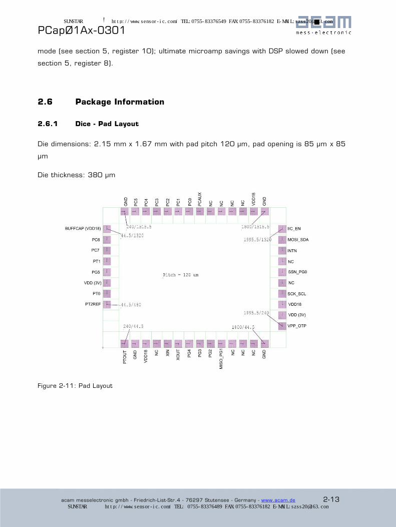
2.6.1 Dice - Pad Layout
Die dimensions: 2.15 mm x 1.67 mm with pad pitch 120 µm, pad opening is 85 µm x 85
µm
Die thickness: 380 µm
Figure 2-11: Pad Layout
SUNSTAR传感与控制 http://www.sensor-ic.com/ TEL:0755-83376549 FAX:0755-83376182 E-MAIL:[email protected]
SUNSTAR自动化 http://www.sensor-ic.com/ TEL: 0755-83376489 FAX:0755-83376182 E-MAIL:[email protected]
® PCapØ1Ax-0301
2-14 acam messelectronic gmbh - Friedrich-List-Str.4 - 76297 Stutensee - Germany - www.acam.de
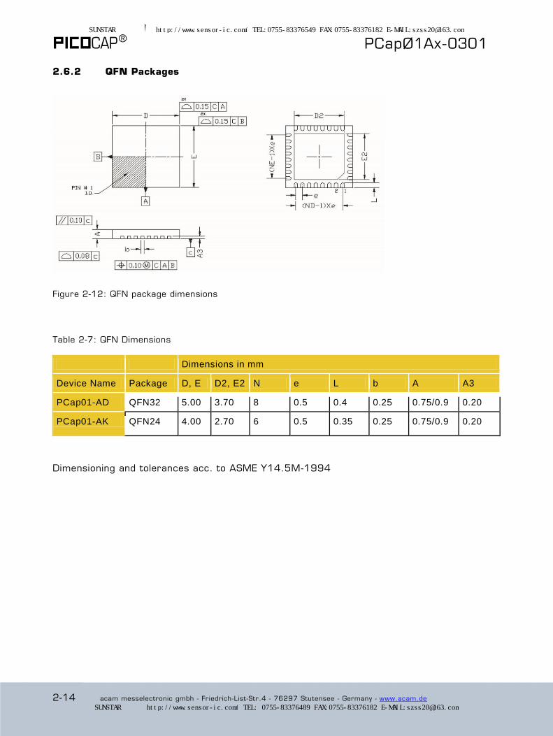
2.6.2 QFN Packages
Figure 2-12: QFN package dimensions
Table 2-7: QFN Dimensions
Dimensions in mm
Device Name Package D, E D2, E2 N e L b A A3
PCap01-AD QFN32 5.00 3.70 8 0.5 0.4 0.25 0.75/0.9 0.20
PCap01-AK QFN24 4.00 2.70 6 0.5 0.35 0.25 0.75/0.9 0.20
Dimensioning and tolerances acc. to ASME Y14.5M-1994
SUNSTAR传感与控制 http://www.sensor-ic.com/ TEL:0755-83376549 FAX:0755-83376182 E-MAIL:[email protected]
SUNSTAR自动化 http://www.sensor-ic.com/ TEL: 0755-83376489 FAX:0755-83376182 E-MAIL:[email protected]

PCapØ1Ax-0301
acam messelectronic gmbh - Friedrich-List-Str.4 - 76297 Stutensee - Germany - www.acam.de 2-15
2.6.3 Pin-Out QFN32 and QFN24 Versions
-AD: All pins are available
Figure 2-13
-AK: Reduced number of capacitor ports, no external oscillator
Figure 2-11
SUNSTAR传感与控制 http://www.sensor-ic.com/ TEL:0755-83376549 FAX:0755-83376182 E-MAIL:[email protected]
SUNSTAR自动化 http://www.sensor-ic.com/ TEL: 0755-83376489 FAX:0755-83376182 E-MAIL:[email protected]
® PCapØ1Ax-0301
2-16 acam messelectronic gmbh - Friedrich-List-Str.4 - 76297 Stutensee - Germany - www.acam.de
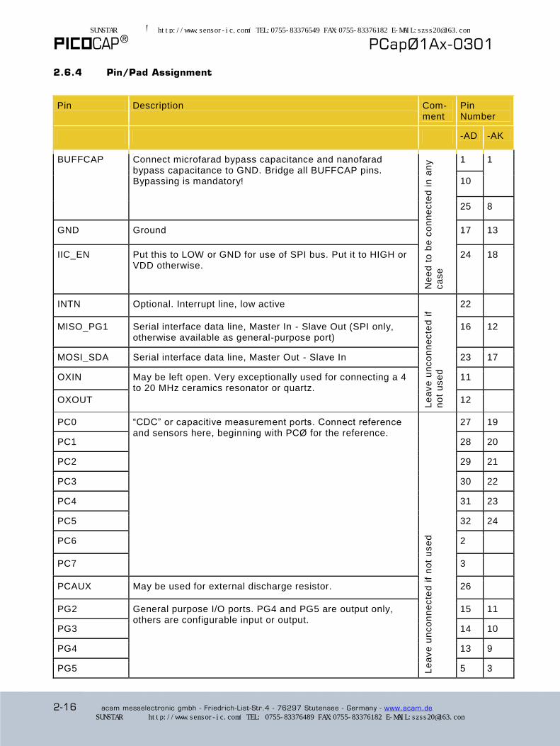
2.6.4 Pin/Pad Assignment
Pin Description Com-ment
Pin Number
-AD -AK
BUFFCAP Connect microfarad bypass capacitance and nanofarad bypass capacitance to GND. Bridge all BUFFCAP pins. Bypassing is mandatory!
Ne
ed
to
be
co
nn
ecte
d i
n a
ny
ca
se
1 1
10
25 8
GND Ground 17 13
IIC_EN Put this to LOW or GND for use of SPI bus. Put it to HIGH or VDD otherwise.
24 18
INTN Optional. Interrupt line, low active
Le
ave
un
co
nn
ecte
d i
f
no
t u
se
d
22
MISO_PG1 Serial interface data line, Master In - Slave Out (SPI only, otherwise available as general-purpose port)
16 12
MOSI_SDA Serial interface data line, Master Out - Slave In 23 17
OXIN May be left open. Very exceptionally used for connecting a 4 to 20 MHz ceramics resonator or quartz.
11
OXOUT 12
PC0 “CDC” or capacitive measurement ports. Connect reference and sensors here, beginning with PCØ for the reference.
Le
ave
un
co
nn
ecte
d i
f n
ot
use
d
27 19
PC1 28 20
PC2 29 21
PC3 30 22
PC4 31 23
PC5 32 24
PC6 2
PC7 3
PCAUX May be used for external discharge resistor. 26
PG2 General purpose I/O ports. PG4 and PG5 are output only, others are configurable input or output.
15 11
PG3 14 10
PG4 13 9
PG5 5 3
SUNSTAR传感与控制 http://www.sensor-ic.com/ TEL:0755-83376549 FAX:0755-83376182 E-MAIL:[email protected]
SUNSTAR自动化 http://www.sensor-ic.com/ TEL: 0755-83376489 FAX:0755-83376182 E-MAIL:[email protected]

PCapØ1Ax-0301
acam messelectronic gmbh - Friedrich-List-Str.4 - 76297 Stutensee - Germany - www.acam.de 2-17
PT0 “RDC” or temperature measurement ports. Connect one side of the external resistive sensors here.
7 5
PT1 4 2
PT2REF When there is an external resistive (temperature measurement) reference, connect it here, otherwise this is the place for a third resistive sensor.
8 6
PTOUT For temperature measurement, connect the other side of the resistive sensors and a 33 nF ceramics capacitor here.
9 7
SCK_SCL Serial interface clock line 20 15
SSN_PG0 SPI interface chip select line, low active. Alternatively general purpose I/O port.
21 16
VDD VDD here, plus bypass capacitance to GND. Bypassing is mandatory!
6 19
4
VPP_OTP Set to 6.5 V during OTP programming. Set back to GND rapidly after the end of the programming process. Keep pin grounded for normal device operation. Apply a 470 kOhm pull-down resistor to this pin.
Co
nn
ect
to
GN
D
18 14
GND ground pad
The ground pad, bottom located, is internally connected to ground. Parallel external grounding is not necessary
- -
SUNSTAR传感与控制 http://www.sensor-ic.com/ TEL:0755-83376549 FAX:0755-83376182 E-MAIL:[email protected]
SUNSTAR自动化 http://www.sensor-ic.com/ TEL: 0755-83376489 FAX:0755-83376182 E-MAIL:[email protected]

® PCapØ1Ax-0301
2-18 acam messelectronic gmbh - Friedrich-List-Str.4 - 76297 Stutensee - Germany - www.acam.de
SUNSTAR传感与控制 http://www.sensor-ic.com/ TEL:0755-83376549 FAX:0755-83376182 E-MAIL:[email protected]
SUNSTAR自动化 http://www.sensor-ic.com/ TEL: 0755-83376489 FAX:0755-83376182 E-MAIL:[email protected]
PCapØ1Ax-0301
acam messelectronic gmbh - Friedrich-List-Str.4 - 76297 Stutensee - Germany - www.acam.de 3-1
3 Converter Frontend
3.1 CDC Measuring Principle ....................................................................... 3-2
3.2 Important CDC Parameters .................................................................... 3-2
3.3 CDC External Circuitry ........................................................................... 3-4
3.4 Connecting the Capacitive Sensors .......................................................... 3-5
3.5 Selecting the Discharge Resistor ............................................................. 3-6
3.6 Compensation Measurement .................................................................. 3-7
3.7 RDC Temperature Measurement ............................................................. 3-8
SUNSTAR传感与控制 http://www.sensor-ic.com/ TEL:0755-83376549 FAX:0755-83376182 E-MAIL:[email protected]
SUNSTAR自动化 http://www.sensor-ic.com/ TEL: 0755-83376489 FAX:0755-83376182 E-MAIL:[email protected]

® PCapØ1Ax-0301
3-2 acam messelectronic gmbh - Friedrich-List-Str.4 - 76297 Stutensee - Germany - www.acam.de
3.1 CDC Measuring Principle
The device uses “discharge time measurement” as a principle for measuring either
capacitance (the CDC unit) or resistivity (the RDC unit). It addresses all ports (PC...,PT...)
in time multiplex.
Figure 3-1 Cycle Time
3.2 Important CDC Parameters
An important notion is “cycle time”, the period of one elementary discharge -and-recharge
cycle, see figure 3-1.
The discharge time is given by the capacitors and the discharge resistor. The cycle time is
the time interval between two discharge time measurements and is set by the user. The
relevant parameter is CMEAS_CYTIME in register 4. The user has to take care that the
charge time and therefore the cycle time is long enough. As default we recommend to
have the cycle time > 2 x discharge time. Otherwise, the capacitors do not get charged
sufficiently. Further, if the cycle time is less than the discharge time the CDC will show a
time-out.
Measurement results are deduced as follows; discharge time ratios equal sensor -to-
reference values:
This equation holds for the CDC, and is similar for the RDC.
SUNSTAR传感与控制 http://www.sensor-ic.com/ TEL:0755-83376549 FAX:0755-83376182 E-MAIL:[email protected]
SUNSTAR自动化 http://www.sensor-ic.com/ TEL: 0755-83376489 FAX:0755-83376182 E-MAIL:[email protected]
PCapØ1Ax-0301
acam messelectronic gmbh - Friedrich-List-Str.4 - 76297 Stutensee - Germany - www.acam.de 3-3
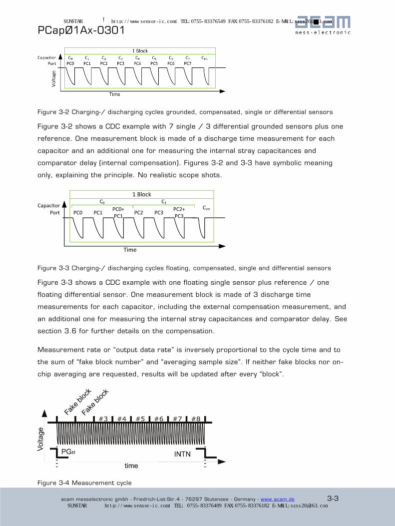
Figure 3-2 Charging-/ discharging cycles grounded, compensated, single or differential sensors
Figure 3-2 shows a CDC example with 7 single / 3 differential grounded sensors plus one
reference. One measurement block is made of a discharge time measurement for each
capacitor and an additional one for measuring the internal stray capacitances and
comparator delay (internal compensation). Figures 3-2 and 3-3 have symbolic meaning
only, explaining the principle. No realistic scope shots.
Figure 3-3 Charging-/ discharging cycles floating, compensated, single and differential sensors
Figure 3-3 shows a CDC example with one floating single sensor plus reference / one
floating differential sensor. One measurement block is made of 3 discharge time
measurements for each capacitor, including the external compensation measurement, and
an additional one for measuring the internal stray capacitances and comparator delay. See
section 3.6 for further details on the compensation.
Measurement rate or “output data rate” is inversely proportional to the cycle time and to
the sum of “fake block number” and “averaging sample size”. If neither fake blocks nor on -
chip averaging are requested, results will be updated after every “block”.
Figure 3-4 Measurement cycle
SUNSTAR传感与控制 http://www.sensor-ic.com/ TEL:0755-83376549 FAX:0755-83376182 E-MAIL:[email protected]
SUNSTAR自动化 http://www.sensor-ic.com/ TEL: 0755-83376489 FAX:0755-83376182 E-MAIL:[email protected]
® PCapØ1Ax-0301
3-4 acam messelectronic gmbh - Friedrich-List-Str.4 - 76297 Stutensee - Germany - www.acam.de
2 single grounded sensors + reference, cycle time = 20 µs: block period = 80 µs
2 fake blocks + 4-fold averaging: measurement period = 480 µs
Maximum update rate = 2,083 Hz
1 single floating sensor + reference, cycle time = 20 µs: block period = 140 µs
2 fake blocks + 8-fold averaging: measurement period = 1400 µs
Maximum update rate = 714 Hz
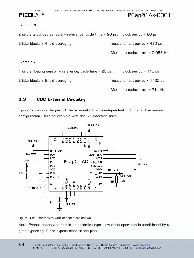
3.3 CDC External Circuitry
Figure 3-5 shows the part of the schematic that is independent from capacitive sensor
configuration. Here an example with the SPI interface used.
Figure 3-5: Schematics with sensors not shown
Note: Bypass capacitors should be ceramics type. Low noise operation is conditioned by a
good bypassing. Place bypass close to the pins.
SUNSTAR传感与控制 http://www.sensor-ic.com/ TEL:0755-83376549 FAX:0755-83376182 E-MAIL:[email protected]
SUNSTAR自动化 http://www.sensor-ic.com/ TEL: 0755-83376489 FAX:0755-83376182 E-MAIL:[email protected]
PCapØ1Ax-0301
acam messelectronic gmbh - Friedrich-List-Str.4 - 76297 Stutensee - Germany - www.acam.de 3-5
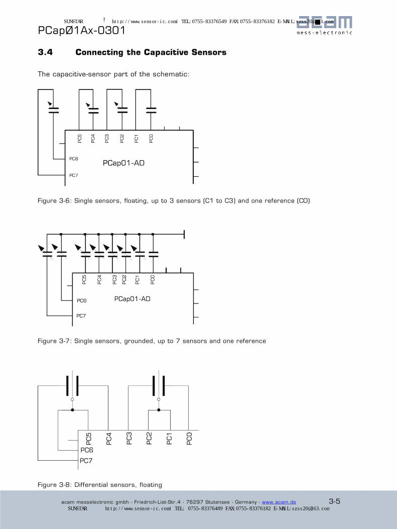
3.4 Connecting the Capacitive Sensors
The capacitive-sensor part of the schematic:
Figure 3-6: Single sensors, floating, up to 3 sensors (C1 to C3) and one reference (C0)
Figure 3-7: Single sensors, grounded, up to 7 sensors and one reference
Figure 3-8: Differential sensors, floating
SUNSTAR传感与控制 http://www.sensor-ic.com/ TEL:0755-83376549 FAX:0755-83376182 E-MAIL:[email protected]
SUNSTAR自动化 http://www.sensor-ic.com/ TEL: 0755-83376489 FAX:0755-83376182 E-MAIL:[email protected]
® PCapØ1Ax-0301
3-6 acam messelectronic gmbh - Friedrich-List-Str.4 - 76297 Stutensee - Germany - www.acam.de
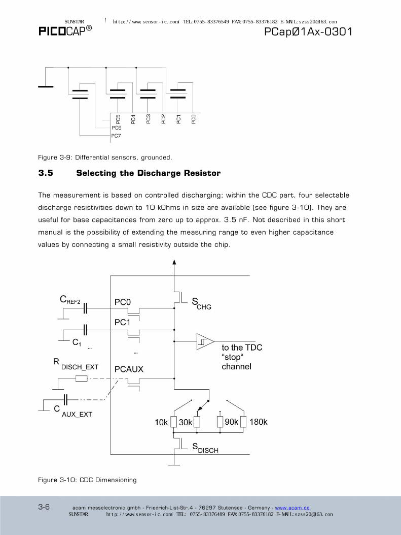
Figure 3-9: Differential sensors, grounded.
3.5 Selecting the Discharge Resistor
The measurement is based on controlled discharging; within the CDC part, four selectable
discharge resistivities down to 10 kOhms in size are available (see figure 3-10). They are
useful for base capacitances from zero up to approx. 3.5 nF. Not described in this short
manual is the possibility of extending the measuring range to even higher capacitance
values by connecting a small resistivity outside the chip.
Figure 3-10: CDC Dimensioning
SUNSTAR传感与控制 http://www.sensor-ic.com/ TEL:0755-83376549 FAX:0755-83376182 E-MAIL:[email protected]
SUNSTAR自动化 http://www.sensor-ic.com/ TEL: 0755-83376489 FAX:0755-83376182 E-MAIL:[email protected]

PCapØ1Ax-0301
acam messelectronic gmbh - Friedrich-List-Str.4 - 76297 Stutensee - Germany - www.acam.de 3-7
3.6 Compensation Measurement
With grounded capacitors the PCap01 offers the possibility to compensate for internal
parasitic capacitances and, having the same effect, the propagation delay of the
comparator. ACAM patents pending.
With floating capacitors we have the additional option to compensate external parasitic
capacitances against ground. On the PCB, the wire capacitance typically refers to ground.
For long wires, it is recommended to use shields which should be grounded at their PCB
side.
Figure 3-11 shows how shielded cables should be connected for compensation of the external parasitic capacitances.
Three measurements are necessary for each capacitor in case of floating sensors; this is
shown in figure 3-12
Figure 3-12 Floating capacitors, external compensation measurements, the three measurements that are made for each floating capacitor.
SUNSTAR传感与控制 http://www.sensor-ic.com/ TEL:0755-83376549 FAX:0755-83376182 E-MAIL:[email protected]
SUNSTAR自动化 http://www.sensor-ic.com/ TEL: 0755-83376489 FAX:0755-83376182 E-MAIL:[email protected]
® PCapØ1Ax-0301
3-8 acam messelectronic gmbh - Friedrich-List-Str.4 - 76297 Stutensee - Germany - www.acam.de
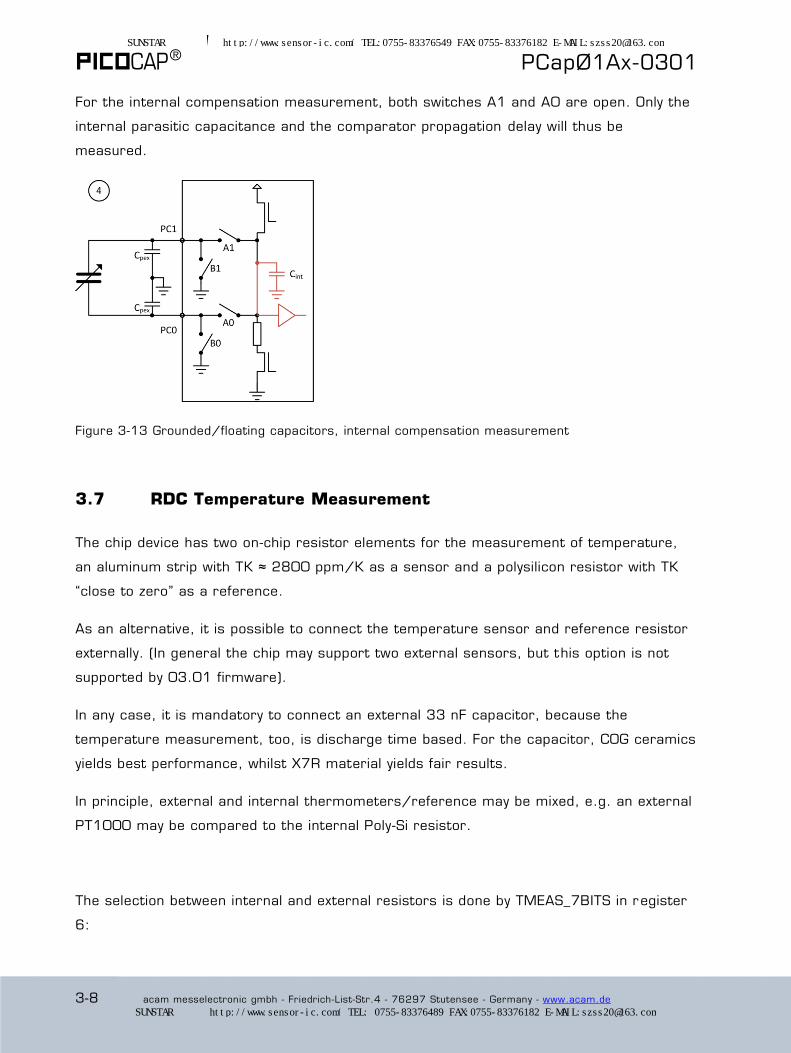
For the internal compensation measurement, both switches A1 and A0 are open. Only the
internal parasitic capacitance and the comparator propagation delay will thus be
measured.
Figure 3-13 Grounded/floating capacitors, internal compensation measurement
3.7 RDC Temperature Measurement
The chip device has two on-chip resistor elements for the measurement of temperature,
an aluminum strip with TK ≈ 2800 ppm/K as a sensor and a polysilicon resistor with TK
“close to zero” as a reference.
As an alternative, it is possible to connect the temperature sensor and reference resistor
externally. (In general the chip may support two external sensors, but this option is not
supported by 03.01 firmware).
In any case, it is mandatory to connect an external 33 nF capacitor, because the
temperature measurement, too, is discharge time based. For the capacitor, C0G ceramics
yields best performance, whilst X7R material yields fair results.
In principle, external and internal thermometers/reference may be mixed, e.g. an external
PT1000 may be compared to the internal Poly-Si resistor.
The selection between internal and external resistors is done by TMEAS_7BITS in register
6:
SUNSTAR传感与控制 http://www.sensor-ic.com/ TEL:0755-83376549 FAX:0755-83376182 E-MAIL:[email protected]
SUNSTAR自动化 http://www.sensor-ic.com/ TEL: 0755-83376489 FAX:0755-83376182 E-MAIL:[email protected]

PCapØ1Ax-0301
acam messelectronic gmbh - Friedrich-List-Str.4 - 76297 Stutensee - Germany - www.acam.de 3-9
A) External solution
Configuration:
Register 4 = ’h XX XX 01 (CMEAS triggered)
Register 5 = ’h CX XX XX
Register 6 = ’h 00 0C 40 (external resistors)
Output data:
Ratio PT1000/Rref as R0/Rref in read register
Res10 (address 13).
Figure 3-14 RDC with external resistors
B) Completely internal solution
Configuration:
Register 4 = ’h XX XX 01 (CMEAS triggered)
Register 5 = ’h CX XX XX
Register 6 = ’h 00 43 40 (external resistors)
Output data:
Ratio R[Al]/R[Si_poly] as R2/Rref in read register Res11
(address 14).
Figure 3-15 RDC with internal resistors
There are various trigger sources for the temperature measurement, set in register 4 by
parameter TMEAS_TRIG_SEL. We strongly recommend to use TMEAS_TRIG_SEL = 1,
trigger by capacitance measurement. With this setting, the temperature measurement
follows directly each Nth capacitance measurement, where N is set by parameter
TMEAS_TRIG_PREDIV in register 5. With TMEAS_TRIG_PREDIV = 0 the temperature
measurement is done with each capacitance measurement. With TMEAS_TRIG_SEL = 0
the temperature measurement is triggered by software, sending opcode ’h8E. If no opcode
is sent the temperature measurement is switched off.
Fir
mw
are R
ela
ted
Fir
mw
are R
ela
ted
SUNSTAR传感与控制 http://www.sensor-ic.com/ TEL:0755-83376549 FAX:0755-83376182 E-MAIL:[email protected]
SUNSTAR自动化 http://www.sensor-ic.com/ TEL: 0755-83376489 FAX:0755-83376182 E-MAIL:[email protected]

® PCapØ1Ax-0301
3-10 acam messelectronic gmbh - Friedrich-List-Str.4 - 76297 Stutensee - Germany - www.acam.de
For low power applications, it is recommended to set the divider TMEAS_TRIG_PREDIV to
such a value that the temperature measurement is done maximum 10 times per second.
Figure 3-16 Temperature Measurement triggered by Capacitance Measurement (continuous mode)
Figure 3-17 Temperature Measurement triggered by Capacitance Measurement (Sequence timer triggered)
Be aware that the resistivity measurement is based on an AC, not a DC, method. So,
cable between sensor and chip may contribute shift and noise through its inductance and
capacitance. Twisted shielded cable may be a good choice, in some cases an active shield
may help.
Issue a start command (op code 0x8C) and begin polling data or watching INTN. See
sections 5.3, 6.5.3 and 6.5.4 for details. What you read is R0/Rref or R2/Rref, a ratio
between two resistivities.
External or internal sensors — you will need to calibrate either solution in a climate
chamber.
SUNSTAR传感与控制 http://www.sensor-ic.com/ TEL:0755-83376549 FAX:0755-83376182 E-MAIL:[email protected]
SUNSTAR自动化 http://www.sensor-ic.com/ TEL: 0755-83376489 FAX:0755-83376182 E-MAIL:[email protected]
PCapØ1Ax-0301
acam messelectronic gmbh - Friedrich-List-Str.4 - 76297 Stutensee - Germany - www.acam.de 4-1
4 Interfaces (Serial And Pulse-Density)
4.1 Serial Interfaces................................................................................... 4-2
4.1.1 Op codes ...................................................................................... 4-2
4.1.2 I2C Compatible Interface .................................................................. 4-3
4.1.3 The 4-wire, SPI interface.................................................................. 4-5
4.2 PDM/PWM and GPIO ........................................................................... 4-7
SUNSTAR传感与控制 http://www.sensor-ic.com/ TEL:0755-83376549 FAX:0755-83376182 E-MAIL:[email protected]
SUNSTAR自动化 http://www.sensor-ic.com/ TEL: 0755-83376489 FAX:0755-83376182 E-MAIL:[email protected]

® PCapØ1Ax-0301
4-2 acam messelectronic gmbh - Friedrich-List-Str.4 - 76297 Stutensee - Germany - www.acam.de
4.1 Serial Interfaces
For operation with a micro-controller, and also for programming the device, two serial
interfaces are available. Only one interface is available at a time, selected through the
voltage applied to the pin “IIC_EN”. Both interfaces are limited to “slave” rank, and both
permit programming:
Pin IIC_EN is connected to GROUND The 4-wire SPI interface is active. General-purpose I/O pins PG0 and PG1 are not available (occupied by SPI).
Pin IIC_EN is connected to VDD The 2-wire I2C interface is active and all general-purpose I/O pins are available, including PG0 and PG1.
Remarks: The general-purpose I/O pins PG2 through PG5 are available in either case. If
no controller interface is needed, put IIC_EN to VDD, not to ground. You must not leave
this pin open.
Once programmed, the device can operate stand-alone. As both interfaces are limited to
slave rank, stand-alone operation with data transfer to an ancillary device (e.g. an LCD
converter or a D/A converter) will necessitate software implementation of a serial
protocol (contact ACAM for details).
4.1.1 Op codes
Table 4-1: 8-Bit Op Code Commands
’h88 Power-up reset. This command resets everything.
’h8A “Initial” or “partial” reset, leaves the SRAM contents and registers unchanged. Resets important parts of the device like the front-end and DSP
’h8C Start a capacitance measurement sequence
’h84 Terminate the write-to-OTP process
’h8E Start temperature measurement
SUNSTAR传感与控制 http://www.sensor-ic.com/ TEL:0755-83376549 FAX:0755-83376182 E-MAIL:[email protected]
SUNSTAR自动化 http://www.sensor-ic.com/ TEL: 0755-83376489 FAX:0755-83376182 E-MAIL:[email protected]
PCapØ1Ax-0301
acam messelectronic gmbh - Friedrich-List-Str.4 - 76297 Stutensee - Germany - www.acam.de 4-3
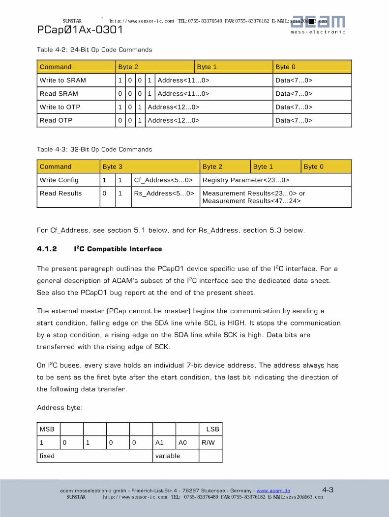
Table 4-2: 24-Bit Op Code Commands
Command Byte 2 Byte 1 Byte 0
Write to SRAM 1 0 0 1 Address<11...0> Data<7...0>
Read SRAM 0 0 0 1 Address<11...0> Data<7...0>
Write to OTP 1 0 1 Address<12...0> Data<7...0>
Read OTP 0 0 1 Address<12...0> Data<7...0>
Table 4-3: 32-Bit Op Code Commands
Command Byte 3 Byte 2 Byte 1 Byte 0
Write Config 1 1 Cf_Address<5...0> Registry Parameter<23...0>
Read Results 0 1 Rs_Address<5...0> Measurement Results<23...0> or Measurement Results<47...24>
For Cf_Address, see section 5.1 below, and for Rs_Address, section 5.3 below.
4.1.2 I2C Compatible Interface
The present paragraph outlines the PCap01 device specific use of the I2C interface. For a
general description of ACAM‘s subset of the I2C interface see the dedicated data sheet.
See also the PCap01 bug report at the end of the present sheet.
The external master (PCap cannot be master) begins the communication by sending a
start condition, falling edge on the SDA line while SCL is HIGH. It stops the communication
by a stop condition, a rising edge on the SDA line while SCK is high. Data bits are
transferred with the rising edge of SCK.
On I2C buses, every slave holds an individual 7-bit device address, The address always has
to be sent as the first byte after the start condition, the last bit indicating the direction of
the following data transfer.
Address byte:
MSB LSB
1 0 1 0 0 A1 A0 R/W
fixed variable
SUNSTAR传感与控制 http://www.sensor-ic.com/ TEL:0755-83376549 FAX:0755-83376182 E-MAIL:[email protected]
SUNSTAR自动化 http://www.sensor-ic.com/ TEL: 0755-83376489 FAX:0755-83376182 E-MAIL:[email protected]
® PCapØ1Ax-0301
4-4 acam messelectronic gmbh - Friedrich-List-Str.4 - 76297 Stutensee - Germany - www.acam.de
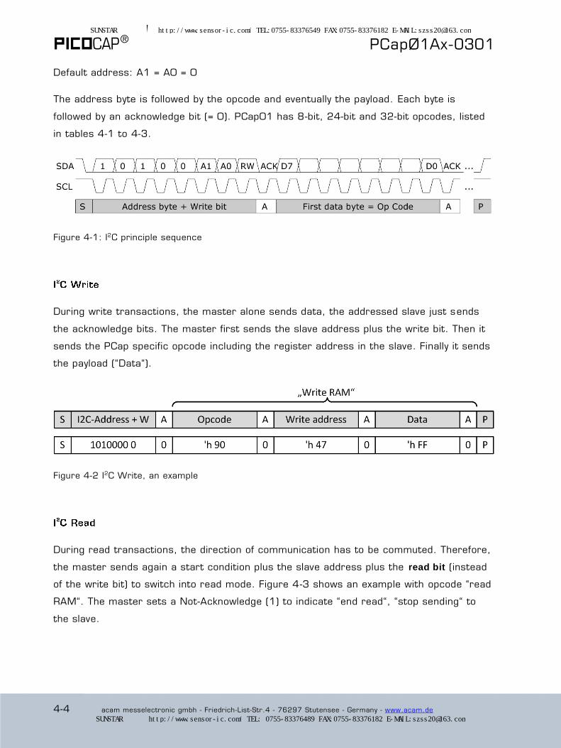
Default address: A1 = A0 = 0
The address byte is followed by the opcode and eventually the payload. Each byte is
followed by an acknowledge bit (= 0). PCap01 has 8-bit, 24-bit and 32-bit opcodes, listed
in tables 4-1 to 4-3.
Figure 4-1: I2C principle sequence
During write transactions, the master alone sends data, the addressed slave just sends
the acknowledge bits. The master first sends the slave address plus the write bit. Then it
sends the PCap specific opcode including the register address in the slave. Finally it sends
the payload (“Data“).
Figure 4-2 I2C Write, an example
During read transactions, the direction of communication has to be commuted. Therefore,
the master sends again a start condition plus the slave address plus the read bit (instead
of the write bit) to switch into read mode. Figure 4-3 shows an example with opcode “read
RAM“. The master sets a Not-Acknowledge (1) to indicate “end read“, “stop sending“ to
the slave.
SUNSTAR传感与控制 http://www.sensor-ic.com/ TEL:0755-83376549 FAX:0755-83376182 E-MAIL:[email protected]
SUNSTAR自动化 http://www.sensor-ic.com/ TEL: 0755-83376489 FAX:0755-83376182 E-MAIL:[email protected]

PCapØ1Ax-0301
acam messelectronic gmbh - Friedrich-List-Str.4 - 76297 Stutensee - Germany - www.acam.de 4-5
Figure 4-3: I2C Read
4.1.3 The 4-wire, SPI interface
Clock Polarity, Clock Phase and Bit Order. The following choices are necessary for
successful operation.
Table 4-4: SPI Clock Polarity, Clock Phase and Bit Order
SPI - Parameter Description Setting
CPOL Clock polarity 0
CPHA Clock phase 1
Mode SPI Mode 1
DORD Bit sequence order 0, MSB first
Timing conditions:
Figure 4-4: SPI Write
SUNSTAR传感与控制 http://www.sensor-ic.com/ TEL:0755-83376549 FAX:0755-83376182 E-MAIL:[email protected]
SUNSTAR自动化 http://www.sensor-ic.com/ TEL: 0755-83376489 FAX:0755-83376182 E-MAIL:[email protected]
® PCapØ1Ax-0301
4-6 acam messelectronic gmbh - Friedrich-List-Str.4 - 76297 Stutensee - Germany - www.acam.de
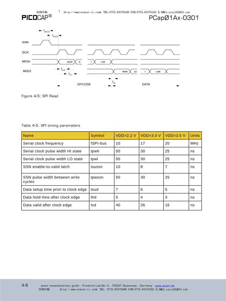
Figure 4-5: SPI Read
Table 4-5: SPI timing parameters
Name Symbol VDD=2.2 V VDD=3.0 V VDD=3.6 V Units
Serial clock frequency fSPI-bus 10 17 20 MHz
Serial clock pulse width HI state tpwh 50 30 25 ns
Serial clock pulse width LO state tpwl 50 30 25 ns
SSN enable-to-valid latch tsussn 10 8 7 ns
SSN pulse width between write cycles
tpwssn 50 30 25 ns
Data setup time prior to clock edge tsud 7 6 5 ns
Data hold time after clock edge thd 5 4 3 ns
Data valid after clock edge tvd 40 26 16 ns
SUNSTAR传感与控制 http://www.sensor-ic.com/ TEL:0755-83376549 FAX:0755-83376182 E-MAIL:[email protected]
SUNSTAR自动化 http://www.sensor-ic.com/ TEL: 0755-83376489 FAX:0755-83376182 E-MAIL:[email protected]

PCapØ1Ax-0301
acam messelectronic gmbh - Friedrich-List-Str.4 - 76297 Stutensee - Germany - www.acam.de 4-7
4.2 PDM/PWM and GPIO
The following table shows the different general purpose ports and their possible
assignment.
Table 4-6: General-Purpose Port Assignment:
External Port Name Description Direction in or out
PG0 SSN (in SPI-Mode) in
DSPØ or DSP2 in(1) / out
FF0 or FF2 in(1)
Pulse0 out
PG1 MISO (in SPI-Mode) out
DSP1 or DSP3 in(1) / out
FF1 or FF3 in(1)
Pulse1 out
PG2 DSPØ or DSP2 in(1) / out
FF0 or FF2 in(1)
Pulse0 out
INTN out
PG3 DSP1 or DSP3 in(1) / out
FF1 or FF3 in(1)
Pulse1 out
PG4 DSP4 (output only) out
PG5 DSP5 (output only) out
(1) These ports provide an optional debouncing filter and an optional pull -up resistor.
SUNSTAR传感与控制 http://www.sensor-ic.com/ TEL:0755-83376549 FAX:0755-83376182 E-MAIL:[email protected]
SUNSTAR自动化 http://www.sensor-ic.com/ TEL: 0755-83376489 FAX:0755-83376182 E-MAIL:[email protected]

® PCapØ1Ax-0301
4-8 acam messelectronic gmbh - Friedrich-List-Str.4 - 76297 Stutensee - Germany - www.acam.de
There is a possibility to generate pulse width or pulse density code as outputs from the
chip, based on the measurement results and using standard firmware (or some other,
possibly derived from Standard). Any of the capacitance or temperature measurement
results can be used to generate the pulsed output, and the selection is made by setting
the pulse1_select (resp. pulse0_select) in register Param2. The pulse codes may be
output through general-purpose ports PGØ and PG1 (or two others). Destination ports are
to be configured as output using the PG_DIR_IN bits in Register 9.
As one can see from above, ports PGØ and PG1 are seemingly not available for pulse
output when assigned to the SPI interface. In most cases, though, where pulse outputs
are wanted, SPI interface is used for programming only. Hence, after programming, the
programmer is removed, pin/pad VPP_OTP is set LOW, and pin/pad IIC_EN is set HIGH.
Once this is done, all PG ports are available for general -purpose use and especially PG0,
PG1 for the pulses.
The pulse-modulated output signal can
be transformed into an analog voltage
through a Low Pass filter. The Pulse
Width Modulated output needs a low
pass filter of higher order, while for
Pulse Density Modulated signal a
simple LP filter is sufficient. Suggested
dimensioning is 220 kOhm / 100 nF,
which smoothes the ripple to less than
1 LSB.
Figure 4-6: PDM Output filtering
For generating the pulsed outputs, the frequency of the carrier clock signal is configurable
to either 8 MHz or 1 MHz or 100 kHz. However, for best results, the “OLF_X2“ 100 kHz
clock is recommended. It can be selected through PI1_CLK_SEL (resp. PI0_CLK_SEL) in
Register 9. The resolution of the Pulse interface has to be configured through PI1_RES
(resp. PI0_RES) in Register 9. The result of measurement from capacitance or
temperature is a 24-bit value. The DSP linearizes this 24 bit result to a 10 bit value
(assuming “10 bit resolution“ setting). The parameters Slope (m) and Offset (b) of the
linear function are configurable in Registers Param3 to Param5. Both, offset and slope
Fir
mw
are R
ela
ted
Fir
mw
are R
ela
ted
SUNSTAR传感与控制 http://www.sensor-ic.com/ TEL:0755-83376549 FAX:0755-83376182 E-MAIL:[email protected]
SUNSTAR自动化 http://www.sensor-ic.com/ TEL: 0755-83376489 FAX:0755-83376182 E-MAIL:[email protected]
PCapØ1Ax-0301
acam messelectronic gmbh - Friedrich-List-Str.4 - 76297 Stutensee - Germany - www.acam.de 4-9
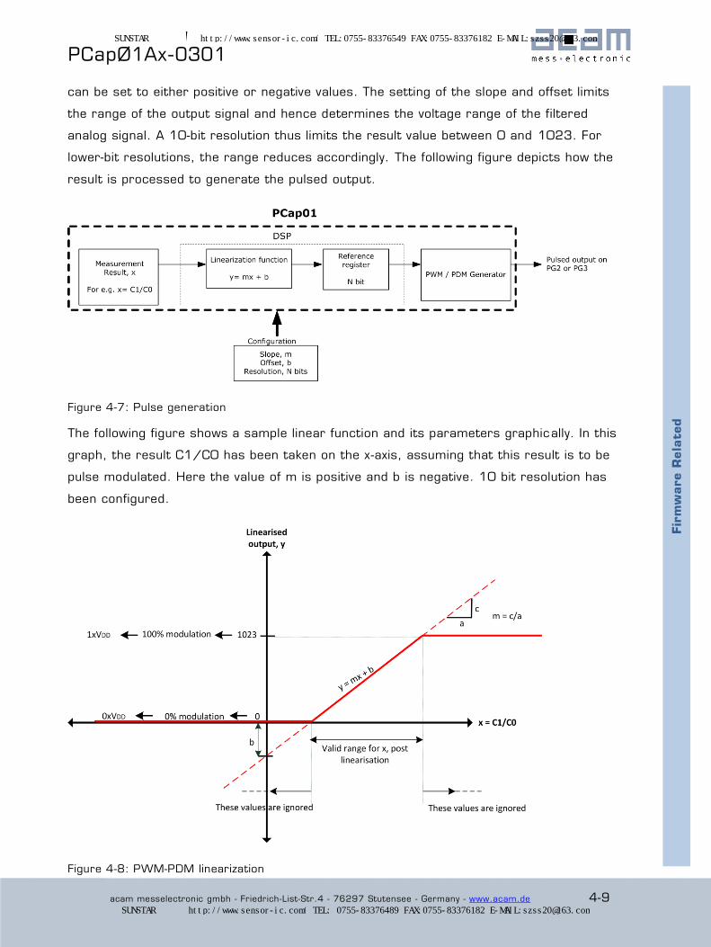
can be set to either positive or negative values. The setting of the slope and offset limits
the range of the output signal and hence determines the voltage range of the filtered
analog signal. A 10-bit resolution thus limits the result value between 0 and 1023. For
lower-bit resolutions, the range reduces accordingly. The following figure depicts how the
result is processed to generate the pulsed output.
Figure 4-7: Pulse generation
The following figure shows a sample linear function and its parameters graphically. In this
graph, the result C1/C0 has been taken on the x-axis, assuming that this result is to be
pulse modulated. Here the value of m is positive and b is negative. 10 bit resolution has
been configured.
Figure 4-8: PWM-PDM linearization
Fir
mw
are R
ela
ted
SUNSTAR传感与控制 http://www.sensor-ic.com/ TEL:0755-83376549 FAX:0755-83376182 E-MAIL:[email protected]
SUNSTAR自动化 http://www.sensor-ic.com/ TEL: 0755-83376489 FAX:0755-83376182 E-MAIL:[email protected]

® PCapØ1Ax-0301
4-10 acam messelectronic gmbh - Friedrich-List-Str.4 - 76297 Stutensee - Germany - www.acam.de
By setting the value of m and b, the linearization function limits the range of the output x
as shown. Values outside these limits are ignored. Thereby knowing the range in which the
results might change, the parameters of the linearization function can be fed accordingly.
The lower limit of the valid range corresponds to 0% modulation (all bits are 0), this is the
least possible value of the output (0). The upper limit of the valid range corresponds to
100% modulation (all bits are 1), and this is the maximum possible value of output. 10 bit
resolution implies that this maximum value is 1023. For lower bit resolutions, this
maximum value will come down accordingly. In terms of voltage, the two limits correspond
to 0V and Vdd.
Applications:
A typical case would be outputting capacitance result through PG0 and temperature
result through PG1. Calculation and copying to the output registers must be
performed by firmware. See help windows in the dedicated PCap01 assembler code
editor.
Useful for applications for which reading the results out through the SPI/ I2C
interface is not suitable because of speed limitations or applications requiring an
analog output signal.
A temperature-coded pulse stream could be low-pass filtered and then directly used
for temperature control.
Please note that the entire linearization task as described here is performed by firmware,
especially the standard firmware.
Fir
mw
are R
ela
ted
SUNSTAR传感与控制 http://www.sensor-ic.com/ TEL:0755-83376549 FAX:0755-83376182 E-MAIL:[email protected]
SUNSTAR自动化 http://www.sensor-ic.com/ TEL: 0755-83376489 FAX:0755-83376182 E-MAIL:[email protected]
PCapØ1Ax-0301
acam messelectronic gmbh - Friedrich-List-Str.4 - 76297 Stutensee - Germany - www.acam.de 5-1
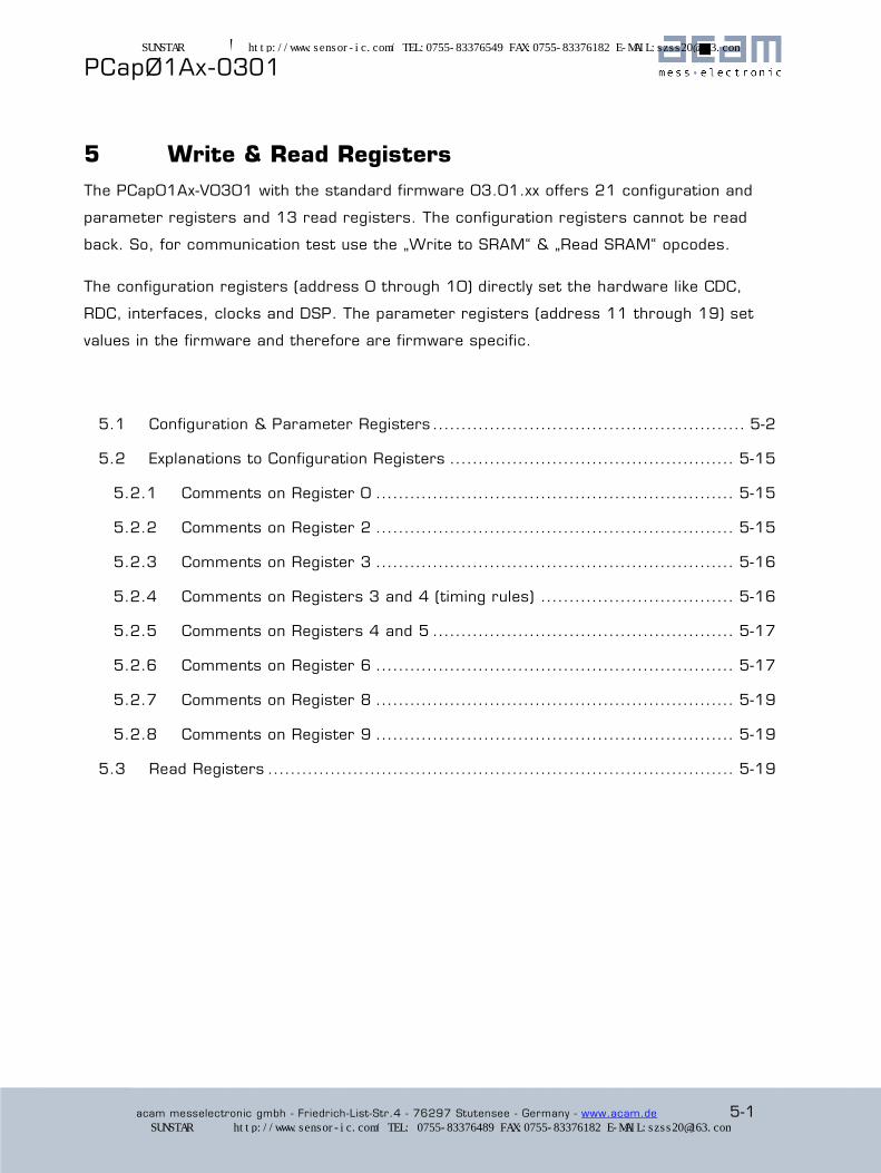
5 Write & Read Registers
The PCap01Ax-V0301 with the standard firmware 03.01.xx offers 21 configuration and
parameter registers and 13 read registers. The configuration registers cannot be read
back. So, for communication test use the „Write to SRAM“ & „Read SRAM“ opcodes.
The configuration registers (address 0 through 10) directly set the hardware like CDC,
RDC, interfaces, clocks and DSP. The parameter registers (address 11 through 19) set
values in the firmware and therefore are firmware specific.
5.1 Configuration & Parameter Registers ....................................................... 5-2
5.2 Explanations to Configuration Registers .................................................. 5-15
5.2.1 Comments on Register 0 ............................................................... 5-15
5.2.2 Comments on Register 2 ............................................................... 5-15
5.2.3 Comments on Register 3 ............................................................... 5-16
5.2.4 Comments on Registers 3 and 4 (timing rules) .................................. 5-16
5.2.5 Comments on Registers 4 and 5 ..................................................... 5-17
5.2.6 Comments on Register 6 ............................................................... 5-17
5.2.7 Comments on Register 8 ............................................................... 5-19
5.2.8 Comments on Register 9 ............................................................... 5-19
5.3 Read Registers .................................................................................. 5-19
SUNSTAR传感与控制 http://www.sensor-ic.com/ TEL:0755-83376549 FAX:0755-83376182 E-MAIL:[email protected]
SUNSTAR自动化 http://www.sensor-ic.com/ TEL: 0755-83376489 FAX:0755-83376182 E-MAIL:[email protected]
® PCapØ1Ax-0301
5-2 acam messelectronic gmbh - Friedrich-List-Str.4 - 76297 Stutensee - Germany - www.acam.de
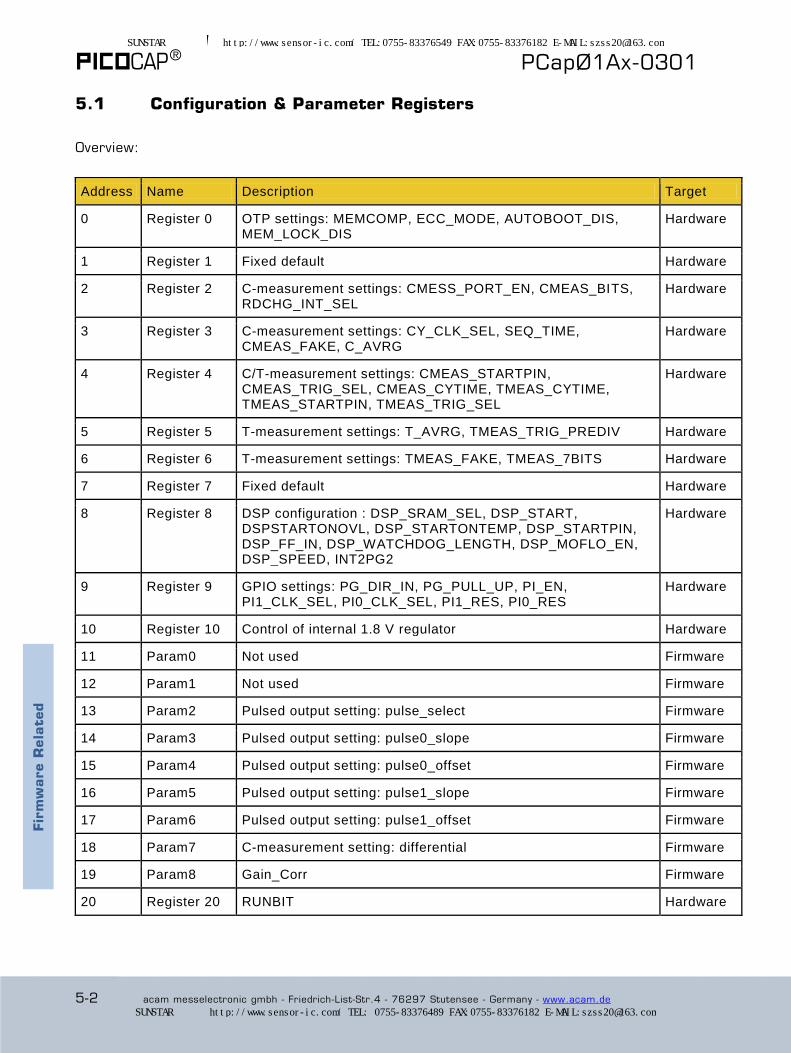
5.1 Configuration & Parameter Registers
Overview:
Address Name Description Target
0 Register 0 OTP settings: MEMCOMP, ECC_MODE, AUTOBOOT_DIS, MEM_LOCK_DIS
Hardware
1 Register 1 Fixed default Hardware
2 Register 2 C-measurement settings: CMESS_PORT_EN, CMEAS_BITS, RDCHG_INT_SEL
Hardware
3 Register 3 C-measurement settings: CY_CLK_SEL, SEQ_TIME, CMEAS_FAKE, C_AVRG
Hardware
4 Register 4 C/T-measurement settings: CMEAS_STARTPIN, CMEAS_TRIG_SEL, CMEAS_CYTIME, TMEAS_CYTIME, TMEAS_STARTPIN, TMEAS_TRIG_SEL
Hardware
5 Register 5 T-measurement settings: T_AVRG, TMEAS_TRIG_PREDIV Hardware
6 Register 6 T-measurement settings: TMEAS_FAKE, TMEAS_7BITS Hardware
7 Register 7 Fixed default Hardware
8 Register 8 DSP configuration : DSP_SRAM_SEL, DSP_START, DSPSTARTONOVL, DSP_STARTONTEMP, DSP_STARTPIN, DSP_FF_IN, DSP_WATCHDOG_LENGTH, DSP_MOFLO_EN, DSP_SPEED, INT2PG2
Hardware
9 Register 9 GPIO settings: PG_DIR_IN, PG_PULL_UP, PI_EN, PI1_CLK_SEL, PI0_CLK_SEL, PI1_RES, PI0_RES
Hardware
10 Register 10 Control of internal 1.8 V regulator Hardware
11 Param0 Not used Firmware
12 Param1 Not used Firmware
13 Param2 Pulsed output setting: pulse_select Firmware
14 Param3 Pulsed output setting: pulse0_slope Firmware
15 Param4 Pulsed output setting: pulse0_offset Firmware
16 Param5 Pulsed output setting: pulse1_slope Firmware
17 Param6 Pulsed output setting: pulse1_offset Firmware
18 Param7 C-measurement setting: differential Firmware
19 Param8 Gain_Corr Firmware
20 Register 20 RUNBIT Hardware
Fir
mw
are R
ela
ted
SUNSTAR传感与控制 http://www.sensor-ic.com/ TEL:0755-83376549 FAX:0755-83376182 E-MAIL:[email protected]
SUNSTAR自动化 http://www.sensor-ic.com/ TEL: 0755-83376489 FAX:0755-83376182 E-MAIL:[email protected]
PCapØ1Ax-0301
acam messelectronic gmbh - Friedrich-List-Str.4 - 76297 Stutensee - Germany - www.acam.de 5-3
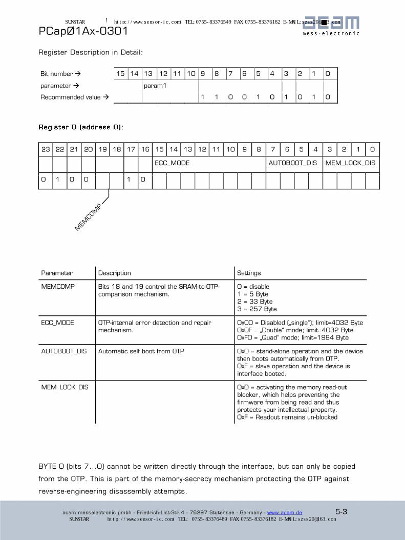
Register Description in Detail:
Bit number 15 14 13 12 11 10 9 8 7 6 5 4 3 2 1 0
parameter param1
Recommended value 1 1 0 0 1 0 1 0 1 0
23 22 21 20 19 18 17 16 15 14 13 12 11 10 9 8 7 6 5 4 3 2 1 0
ECC_MODE AUTOBOOT_DIS MEM_LOCK_DIS
0 1 0 0 1 0
Parameter Description Settings
MEMCOMP Bits 18 and 19 control the SRAM-to-OTP-
comparison mechanism. 0 = disable
1 = 5 Byte 2 = 33 Byte 3 = 257 Byte
ECC_MODE OTP-internal error detection and repair mechanism.
0x00 = Disabled („single“); limit=4032 Byte 0x0F = „Double“ mode; limit=4032 Byte 0xF0 = „Quad“ mode; limit=1984 Byte
AUTOBOOT_DIS Automatic self boot from OTP 0x0 = stand-alone operation and the device then boots automatically from OTP. 0xF = slave operation and the device is
interface booted.
MEM_LOCK_DIS 0x0 = activating the memory read-out blocker, which helps preventing the
firmware from being read and thus protects your intellectual property. 0xF = Readout remains un-blocked
BYTE 0 (bits 7...0) cannot be written directly through the interface, but can only be copied
from the OTP. This is part of the memory-secrecy mechanism protecting the OTP against
reverse-engineering disassembly attempts.
SUNSTAR传感与控制 http://www.sensor-ic.com/ TEL:0755-83376549 FAX:0755-83376182 E-MAIL:[email protected]
SUNSTAR自动化 http://www.sensor-ic.com/ TEL: 0755-83376489 FAX:0755-83376182 E-MAIL:[email protected]

® PCapØ1Ax-0301
5-4 acam messelectronic gmbh - Friedrich-List-Str.4 - 76297 Stutensee - Germany - www.acam.de
23 22 21 20 19 18 17 16 15 14 13 12 11 10 9 8 7 6 5 4 3 2 1 0
LF_CLK_SEL OLF_FTUNE
OLF_TUNE
0 0 1 0 0 0 0 0 0 0 0 1 0 0 0 0 0 0 1 0 0 0 1 0
Parameter Describtion Settings
OLF_TUNE Setting of the internal oscillator frequency 0x35 - 10 kHz
0x22 - 50 kHz 0x13 - 100 kHz 0x04 - 200 kHz
Recommended default setting: 0x22 (50 kHz) default
The internal RC oscillator varies over voltage and temperature, please see
Chapter 2.
23 22 21 20 19 18 17 16 15 14 13 12 11 10 9 8 7 6 5 4 3 2 1 0
CMEAS_PORT_EN
0 0 0 0 1 0 1 1
SUNSTAR传感与控制 http://www.sensor-ic.com/ TEL:0755-83376549 FAX:0755-83376182 E-MAIL:[email protected]
SUNSTAR自动化 http://www.sensor-ic.com/ TEL: 0755-83376489 FAX:0755-83376182 E-MAIL:[email protected]

PCapØ1Ax-0301
acam messelectronic gmbh - Friedrich-List-Str.4 - 76297 Stutensee - Germany - www.acam.de 5-5
Parameter Description Settings
CMEAS_PORT_EN CDC port mask Bit 16 enables port PC0, bit 17 enables
PC1 and so forth.
CMEAS_SCHEME Sensor connecting scheme, see section 3.4
For differential capacitors and only for them, Param7 has to be set, too.
b‘00 = grounded single capacitances b‘00 = grounded differential caps (same)
b‘01 = floating single capacitances b‘10 = floating differential capacitances
CMEAS_DUMMY_EN Selection of mirror symmetric charge and
discharge for differential capacitors, avoiding mechanical stress
0 = off
1 = activated
COMPENS_EXT_DIS Turn off compensation measurement for
external parasitic capacitances 0 = external compensation activated
1 = external compensation disabled
COMPENS_INT_DIS Turn off compensation measurement for internal parasitic capacitances
0 = internal compensation activated 1 = internal compensation disabled
RDCHG_INT_SEL Selection of internal discharge resistor b‘100 = 180 kOhm b‘101 = 90 kOhm b‘110 = 30 kOhm
b‘111 = 10 kOhm
STRAYCOMP Disabling of internal and/or external stray capacitance compensation
00 - Both active 01 - External stray compensation
10 - Internal stray compensation 11 - No compensation active
23 22 21 20 19 18 17 16 15 14 13 12 11 10 9 8 7 6 5 4 3 2 1 0
SEQ_TIME C_AVRG
0 0 0 0
Parameter Description Settings
SEQ_TIME Sets the trigger period in timer-triggered
mode (register 4, TMEAS_TRIG_SEL = 2).
0 = off
Otherwise, if s = SEQ_TIME , the trigger period will be 20 µs * 2 ^ (s+1) with 1 ≤ s ≤ 24.
SUNSTAR传感与控制 http://www.sensor-ic.com/ TEL:0755-83376549 FAX:0755-83376182 E-MAIL:[email protected]
SUNSTAR自动化 http://www.sensor-ic.com/ TEL: 0755-83376489 FAX:0755-83376182 E-MAIL:[email protected]
® PCapØ1Ax-0301
5-6 acam messelectronic gmbh - Friedrich-List-Str.4 - 76297 Stutensee - Germany - www.acam.de
CMEAS_FAKE Sets the number of CDC fake blocks per
sequence, variable from zero to four.
00 - no fake measurement
01 - 1 fake block 10 - 2 fake blocks 11 - 4 fake blocks
C_AVRG Sample size for averaging the CDC results. Zero is ignored and counts as one.
The signal-to-noise ratio will approximately improve proportionally to the square root of C_AVRG
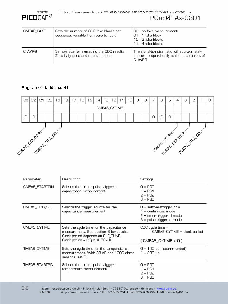
23 22 21 20 19 18 17 16 15 14 13 12 11 10 9 8 7 6 5 4 3 2 1 0
CMEAS_CYTIME
0 0 0 0 0
Parameter Description Settings
CMEAS_STARTPIN Selects the pin for pulse-triggered capacitance measurement
0 = PG0 1 = PG1
2 = PG2 3 = PG3
CMEAS_TRIG_SEL Selects the trigger source for the
capacitance measurement 0 = softwaretrigger only
1 = continuous mode 2 = timer-triggered mode 3 = pulse-triggered mode
CMEAS_CYTIME Sets the cycle time for the capacitance measurement. See section 3 for details. Clock period depends on OLF_TUNE.
Clock period = 20µs @ 50kHz
CDC cycle time = CMEAS_CYTIME * clock period
( CMEAS_CYTIME > 0 )
TMEAS_CYTIME Sets the cycle time for the temperature
measurement. With 33 nF and 1000 ohms sensors, set 0.
0 = 140 µs (recommended)
1 = 280 µs
TMEAS_STARTPIN Selects the pin for pulse-triggered
temperature measurement 0 = PG0
1 = PG1 2 = PG2 3 = PG3
SUNSTAR传感与控制 http://www.sensor-ic.com/ TEL:0755-83376549 FAX:0755-83376182 E-MAIL:[email protected]
SUNSTAR自动化 http://www.sensor-ic.com/ TEL: 0755-83376489 FAX:0755-83376182 E-MAIL:[email protected]
PCapØ1Ax-0301
acam messelectronic gmbh - Friedrich-List-Str.4 - 76297 Stutensee - Germany - www.acam.de 5-7
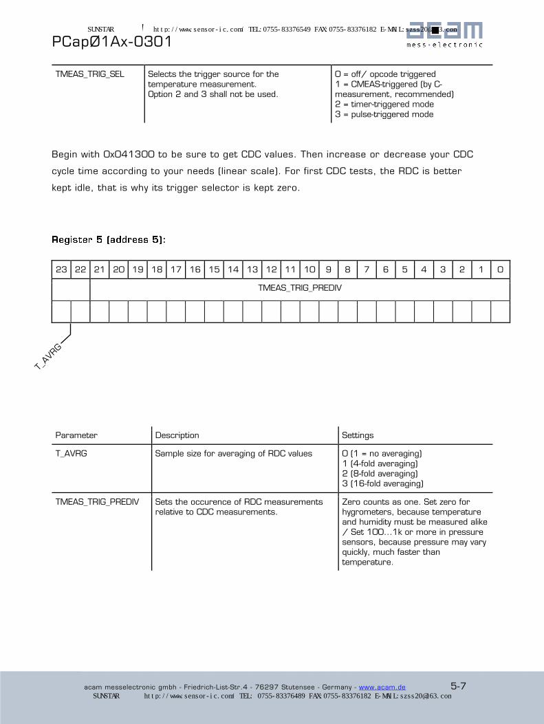
TMEAS_TRIG_SEL Selects the trigger source for the
temperature measurement. Option 2 and 3 shall not be used.
0 = off/ opcode triggered
1 = CMEAS-triggered (by C-measurement, recommended) 2 = timer-triggered mode
3 = pulse-triggered mode
Begin with 0x041300 to be sure to get CDC values. Then increase or decrease your CDC
cycle time according to your needs (linear scale). For first CDC tests, the RDC is better
kept idle, that is why its trigger selector is kept zero.
23 22 21 20 19 18 17 16 15 14 13 12 11 10 9 8 7 6 5 4 3 2 1 0
TMEAS_TRIG_PREDIV
Parameter Description Settings
T_AVRG Sample size for averaging of RDC values 0 (1 = no averaging)
1 (4-fold averaging) 2 (8-fold averaging) 3 (16-fold averaging)
TMEAS_TRIG_PREDIV Sets the occurence of RDC measurements relative to CDC measurements.
Zero counts as one. Set zero for hygrometers, because temperature and humidity must be measured alike
/ Set 100...1k or more in pressure sensors, because pressure may vary quickly, much faster than
temperature.
SUNSTAR传感与控制 http://www.sensor-ic.com/ TEL:0755-83376549 FAX:0755-83376182 E-MAIL:[email protected]
SUNSTAR自动化 http://www.sensor-ic.com/ TEL: 0755-83376489 FAX:0755-83376182 E-MAIL:[email protected]
® PCapØ1Ax-0301
5-8 acam messelectronic gmbh - Friedrich-List-Str.4 - 76297 Stutensee - Germany - www.acam.de
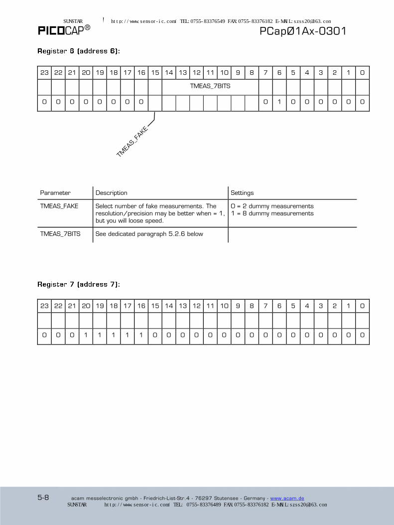
23 22 21 20 19 18 17 16 15 14 13 12 11 10 9 8 7 6 5 4 3 2 1 0
TMEAS_7BITS
0 0 0 0 0 0 0 0 0 1 0 0 0 0 0 0
Parameter Description Settings
TMEAS_FAKE Select number of fake measurements. The resolution/precision may be better when = 1, but you will loose speed.
0 = 2 dummy measurements 1 = 8 dummy measurements
TMEAS_7BITS See dedicated paragraph 5.2.6 below
23 22 21 20 19 18 17 16 15 14 13 12 11 10 9 8 7 6 5 4 3 2 1 0
0 0 0 1 1 1 1 1 0 0 0 0 0 0 0 0 0 0 0 0 0 0 0 0
SUNSTAR传感与控制 http://www.sensor-ic.com/ TEL:0755-83376549 FAX:0755-83376182 E-MAIL:[email protected]
SUNSTAR自动化 http://www.sensor-ic.com/ TEL: 0755-83376489 FAX:0755-83376182 E-MAIL:[email protected]
PCapØ1Ax-0301
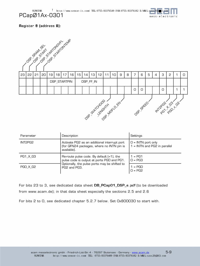
acam messelectronic gmbh - Friedrich-List-Str.4 - 76297 Stutensee - Germany - www.acam.de 5-9
23 22 21 20 19 18 17 16 15 14 13 12 11 10 9 8 7 6 5 4 3 2 1 0
DSP_STARTPIN DSP_FF_IN
0 0 0 1 1
Parameter Description Settings
INT2PG2 Activate PG2 as an additional interrupt port (for QFN24 packages, where no INTN pin is available).
0 = INTN port only 1 = INTN and PG2 in parallel
PG1_X_G3 Re-route pulse code. By default (=1), the pulse code is output at ports PG0 and PG1. Optionally, the pulse ports may be shifted to
PG2 and PG3.
1 = PG1 0 = PG3
PG0_X_G2 1 = PG0
0 = PG2
For bits 23 to 3, see dedicated data sheet (to be downloaded
from www.acam.de); in that data sheet especially the sections 2.5 and 2.6
For bits 2 to 0, see dedicated chapter 5.2.7 below. Set 0x800030 to start with.
SUNSTAR传感与控制 http://www.sensor-ic.com/ TEL:0755-83376549 FAX:0755-83376182 E-MAIL:[email protected]
SUNSTAR自动化 http://www.sensor-ic.com/ TEL: 0755-83376489 FAX:0755-83376182 E-MAIL:[email protected]
® PCapØ1Ax-0301
5-10 acam messelectronic gmbh - Friedrich-List-Str.4 - 76297 Stutensee - Germany - www.acam.de
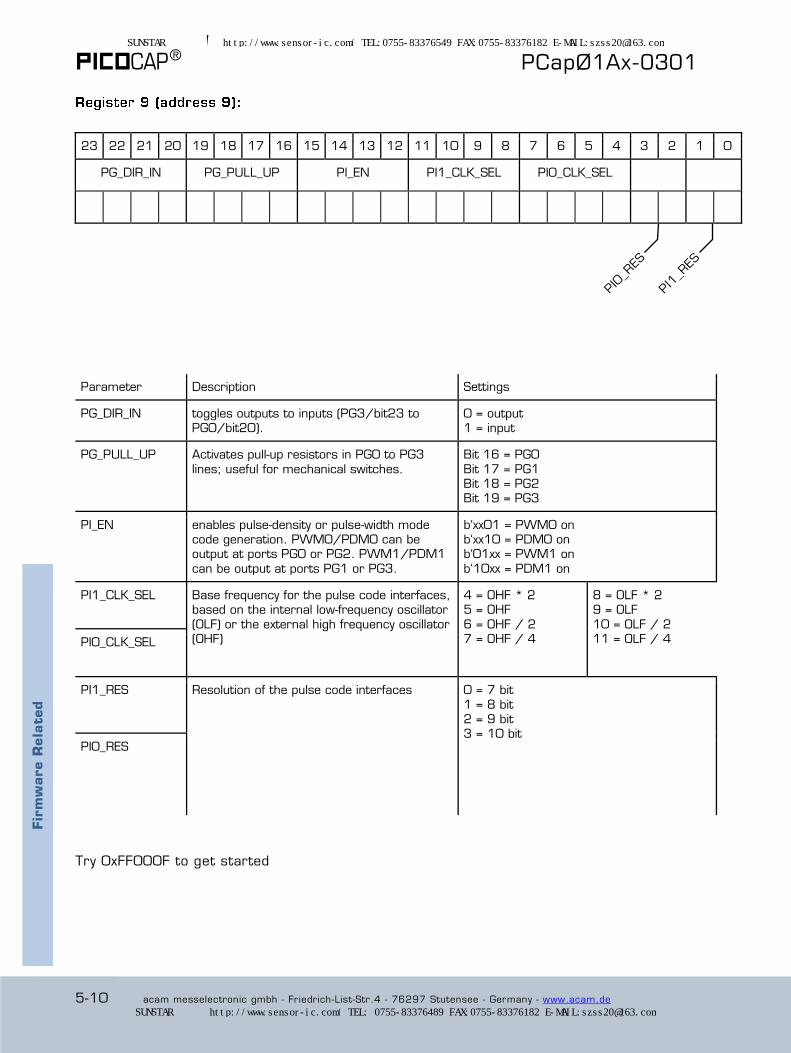
23 22 21 20 19 18 17 16 15 14 13 12 11 10 9 8 7 6 5 4 3 2 1 0
PG_DIR_IN PG_PULL_UP PI_EN PI1_CLK_SEL PI0_CLK_SEL
Parameter Description Settings
PG_DIR_IN toggles outputs to inputs (PG3/bit23 to PG0/bit20).
0 = output 1 = input
PG_PULL_UP Activates pull-up resistors in PG0 to PG3
lines; useful for mechanical switches.
Bit 16 = PG0
Bit 17 = PG1 Bit 18 = PG2 Bit 19 = PG3
PI_EN enables pulse-density or pulse-width mode code generation. PWM0/PDM0 can be output at ports PG0 or PG2. PWM1/PDM1
can be output at ports PG1 or PG3.
b‘xx01 = PWM0 on b‘xx10 = PDM0 on b‘01xx = PWM1 on
b‘10xx = PDM1 on
PI1_CLK_SEL Base frequency for the pulse code interfaces, based on the internal low-frequency oscillator
(OLF) or the external high frequency oscillator (OHF)
4 = OHF * 2 5 = OHF
6 = OHF / 2 7 = OHF / 4
8 = OLF * 2 9 = OLF
10 = OLF / 2 11 = OLF / 4 PI0_CLK_SEL
PI1_RES Resolution of the pulse code interfaces 0 = 7 bit
1 = 8 bit 2 = 9 bit 3 = 10 bit
PI0_RES
Try 0xFF000F to get started
Fir
mw
are R
ela
ted
SUNSTAR传感与控制 http://www.sensor-ic.com/ TEL:0755-83376549 FAX:0755-83376182 E-MAIL:[email protected]
SUNSTAR自动化 http://www.sensor-ic.com/ TEL: 0755-83376489 FAX:0755-83376182 E-MAIL:[email protected]

PCapØ1Ax-0301
acam messelectronic gmbh - Friedrich-List-Str.4 - 76297 Stutensee - Germany - www.acam.de 5-11
Fir
mw
are R
ela
ted
23 22 21 20 19 18 17 16 15 14 13 12 11 10 9 8 7 6 5 4 3 2 1 0
V_CORE_CTL
0 0 0 1 1 0 0 0 0 0 0 0 0 0 0 0
Parameter Description Settings
V_CORE_CTL Controls the 1.8 V core voltage regulator. The low-current setting permits a better
resolution but puts restrictions onto RDC speed and timing. See examples in section 6.5.2 to 6.5.4
0x47 = Standard 0x87 = Low-current
23 22 21 20 19 18 17 16 15 14 13 12 11 10 9 8 7 6 5 4 3 2 1 0
23 22 21 20 19 18 17 16 15 14 13 12 11 10 9 8 7 6 5 4 3 2 1 0
23 22 21 20 19 18 17 16 15 14 13 12 11 10 9 8 7 6 5 4 3 2 1 0
pulse1_select pulse0_select
SUNSTAR传感与控制 http://www.sensor-ic.com/ TEL:0755-83376549 FAX:0755-83376182 E-MAIL:[email protected]
SUNSTAR自动化 http://www.sensor-ic.com/ TEL: 0755-83376489 FAX:0755-83376182 E-MAIL:[email protected]
® PCapØ1Ax-0301
5-12 acam messelectronic gmbh - Friedrich-List-Str.4 - 76297 Stutensee - Germany - www.acam.de
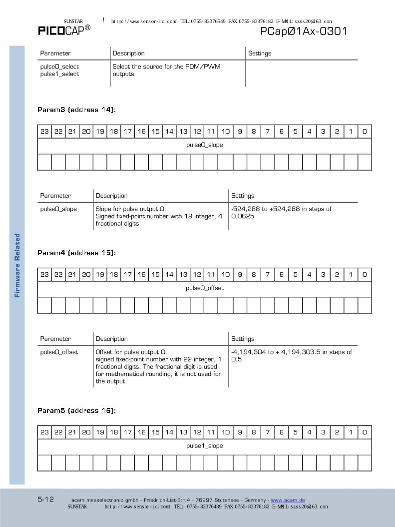
Parameter Description Settings
pulse0_select
pulse1_select
Select the source for the PDM/PWM
outputs
23 22 21 20 19 18 17 16 15 14 13 12 11 10 9 8 7 6 5 4 3 2 1 0
pulse0_slope
Parameter Description Settings
pulse0_slope Slope for pulse output 0.
Signed fixed-point number with 19 integer, 4 fractional digits
-524,288 to +524,288 in steps of
0.0625
23 22 21 20 19 18 17 16 15 14 13 12 11 10 9 8 7 6 5 4 3 2 1 0
pulse0_offset
Parameter Description Settings
pulse0_offset Offset for pulse output 0. signed fixed-point number with 22 integer, 1
fractional digits. The fractional digit is used for mathematical rounding, it is not used for the output.
-4,194,304 to + 4,194,303.5 in steps of 0.5
23 22 21 20 19 18 17 16 15 14 13 12 11 10 9 8 7 6 5 4 3 2 1 0
pulse1_slope
Fir
mw
are R
ela
ted
SUNSTAR传感与控制 http://www.sensor-ic.com/ TEL:0755-83376549 FAX:0755-83376182 E-MAIL:[email protected]
SUNSTAR自动化 http://www.sensor-ic.com/ TEL: 0755-83376489 FAX:0755-83376182 E-MAIL:[email protected]

PCapØ1Ax-0301
acam messelectronic gmbh - Friedrich-List-Str.4 - 76297 Stutensee - Germany - www.acam.de 5-13
Parameter Description Settings
pulse1_slope Slope for pulse output 1.
Signed fixed-point number with 19 integer, 4 fractional digits
-524,288 to +524,288 in steps of
0.0625
23 22 21 20 19 18 17 16 15 14 13 12 11 10 9 8 7 6 5 4 3 2 1 0
pulse1_offset
Parameter Description Settings
pulse1_offset Offset for pulse output 1.
signed fixed-point number with 22 integer, 1 fractional digits. The fractional digit is used for mathematical rounding, it is not used for
the output.
-4,194,304 to + 4,194,303.5 in steps of
0.5
23 22 21 20 19 18 17 16 15 14 13 12 11 10 9 8 7 6 5 4 3 2 1 0
Parameter Description Settings
differential Selects between single and differential
sensors
0 = Single
1 = Differential
Fir
mw
are R
ela
ted
SUNSTAR传感与控制 http://www.sensor-ic.com/ TEL:0755-83376549 FAX:0755-83376182 E-MAIL:[email protected]
SUNSTAR自动化 http://www.sensor-ic.com/ TEL: 0755-83376489 FAX:0755-83376182 E-MAIL:[email protected]

® PCapØ1Ax-0301
5-14 acam messelectronic gmbh - Friedrich-List-Str.4 - 76297 Stutensee - Germany - www.acam.de
23 22 21 20 19 18 17 16 15 14 13 12 11 10 9 8 7 6 5 4 3 2 1 0
Gain_Corr
Parameter Description Settings
Gain_Corr Multiplication factor for internal compensation
measurement. Unsigned fixed-point number with 3 integer and 21 fractional digits.
0 to 7.9999995
Standard value is h‘200000, meaning d‘1.000000
23 22 21 20 19 18 17 16 15 14 13 12 11 10 9 8 7 6 5 4 3 2 1 0
0 0 0 0 0 0 0 0 0 0 0 0 0 0 0 0 0 0 0 0 0 0 0
Parameter Description Settings
RUNBIT RUNBIT=1 must be the last parameter
written. Please set RUNBIT=0 before making any modifications to the registry.
0 = protects the device and keeps it idle
during configuration and forces the DSP to stand still.
1 = activates the run mode
SUNSTAR传感与控制 http://www.sensor-ic.com/ TEL:0755-83376549 FAX:0755-83376182 E-MAIL:[email protected]
SUNSTAR自动化 http://www.sensor-ic.com/ TEL: 0755-83376489 FAX:0755-83376182 E-MAIL:[email protected]
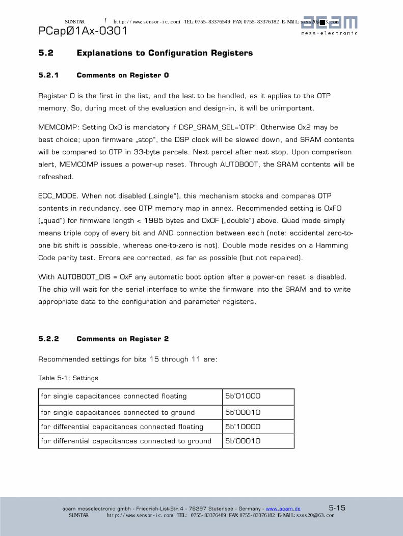
PCapØ1Ax-0301
acam messelectronic gmbh - Friedrich-List-Str.4 - 76297 Stutensee - Germany - www.acam.de 5-15
5.2 Explanations to Configuration Registers
5.2.1 Comments on Register 0
Register 0 is the first in the list, and the last to be handled, as it applies to the OTP
memory. So, during most of the evaluation and design-in, it will be unimportant.
MEMCOMP: Setting 0x0 is mandatory if DSP_SRAM_SEL=‘OTP‘. Otherwise 0x2 may be
best choice; upon firmware „stop“, the DSP clock will be slowed down, and SRAM contents
will be compared to OTP in 33-byte parcels. Next parcel after next stop. Upon comparison
alert, MEMCOMP issues a power-up reset. Through AUTOBOOT, the SRAM contents will be
refreshed.
ECC_MODE. When not disabled („single“), this mechan ism stocks and compares OTP
contents in redundancy, see OTP memory map in annex. Recommended setting is 0xF0
(„quad“) for firmware length < 1985 bytes and 0x0F („double“) above. Quad mode simply
means triple copy of every bit and AND connection between each (note: accidental zero-to-
one bit shift is possible, whereas one-to-zero is not). Double mode resides on a Hamming
Code parity test. Errors are corrected, as far as possible (but not repaired).
With AUTOBOOT_DIS = 0xF any automatic boot option after a power-on reset is disabled.
The chip will wait for the serial interface to write the firmware into the SRAM and to write
appropriate data to the configuration and parameter registers.
5.2.2 Comments on Register 2
Recommended settings for bits 15 through 11 are:
Table 5-1: Settings
for single capacitances connected floating 5b'01000
for single capacitances connected to ground 5b'00010
for differential capacitances connected floating 5b'10000
for differential capacitances connected to ground 5b'00010
SUNSTAR传感与控制 http://www.sensor-ic.com/ TEL:0755-83376549 FAX:0755-83376182 E-MAIL:[email protected]
SUNSTAR自动化 http://www.sensor-ic.com/ TEL: 0755-83376489 FAX:0755-83376182 E-MAIL:[email protected]
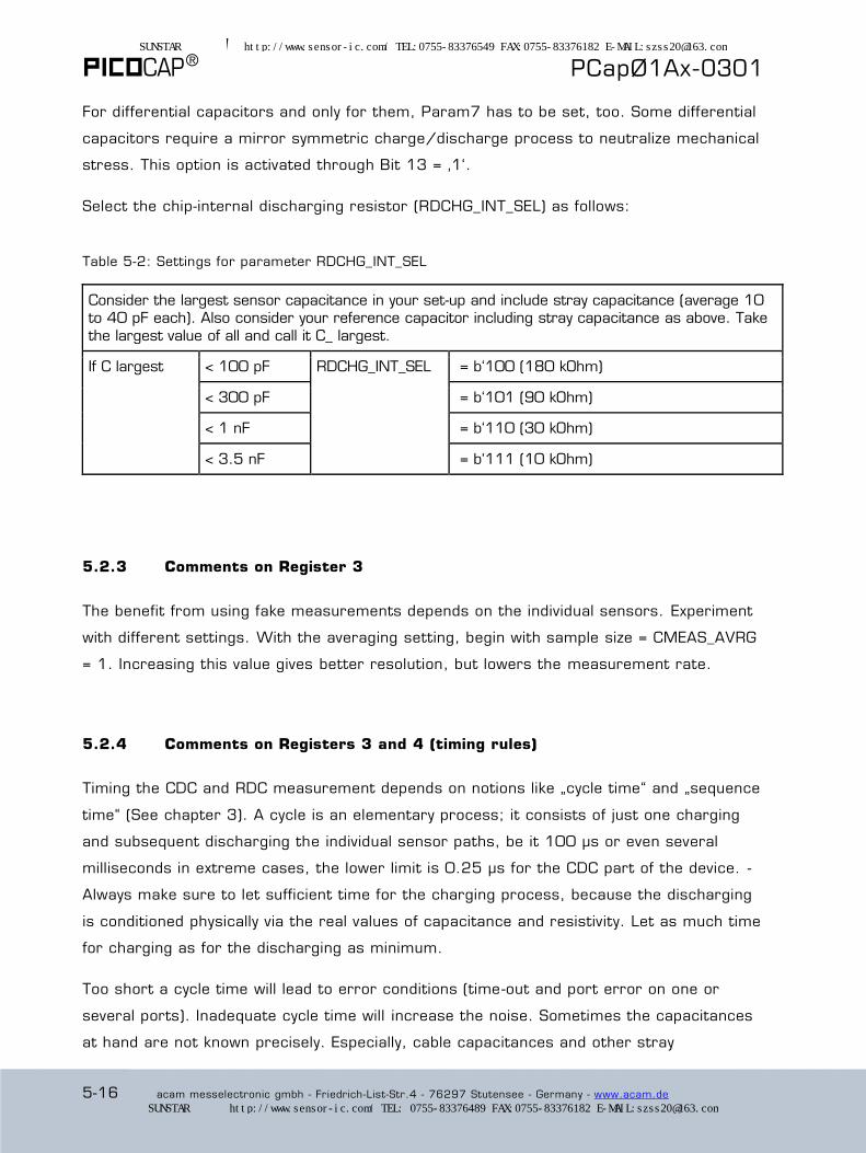
® PCapØ1Ax-0301
5-16 acam messelectronic gmbh - Friedrich-List-Str.4 - 76297 Stutensee - Germany - www.acam.de
For differential capacitors and only for them, Param7 has to be set, too. Some differential
capacitors require a mirror symmetric charge/discharge process to neutralize mechanical
stress. This option is activated through Bit 13 = ‚1‘.
Select the chip-internal discharging resistor (RDCHG_INT_SEL) as follows:
Table 5-2: Settings for parameter RDCHG_INT_SEL
Consider the largest sensor capacitance in your set-up and include stray capacitance (average 10 to 40 pF each). Also consider your reference capacitor including stray capacitance as above. Take
the largest value of all and call it C_ largest.
If C largest < 100 pF RDCHG_INT_SEL = b‘100 (180 kOhm)
< 300 pF = b‘101 (90 kOhm)
< 1 nF = b‘110 (30 kOhm)
< 3.5 nF = b‘111 (10 kOhm)
5.2.3 Comments on Register 3
The benefit from using fake measurements depends on the individual sensors. Experiment
with different settings. With the averaging setting, begin with sample size = CMEAS_AVRG
= 1. Increasing this value gives better resolution, but lowers the measurement rate.
5.2.4 Comments on Registers 3 and 4 (timing rules)
Timing the CDC and RDC measurement depends on notions like „cycle time“ and „sequence
time“ (See chapter 3). A cycle is an elementary process; it consists of just one charging
and subsequent discharging the individual sensor paths, be it 100 µs or even several
milliseconds in extreme cases, the lower limit is 0.25 µs for the CDC part of the device. -
Always make sure to let sufficient time for the charging process, because the discharging
is conditioned physically via the real values of capacitance and resistivity. Let as much time
for charging as for the discharging as minimum.
Too short a cycle time will lead to error conditions (time-out and port error on one or
several ports). Inadequate cycle time will increase the noise. Sometimes the capacitances
at hand are not known precisely. Especially, cable capacitances and other stray
SUNSTAR传感与控制 http://www.sensor-ic.com/ TEL:0755-83376549 FAX:0755-83376182 E-MAIL:[email protected]
SUNSTAR自动化 http://www.sensor-ic.com/ TEL: 0755-83376489 FAX:0755-83376182 E-MAIL:[email protected]

PCapØ1Ax-0301
acam messelectronic gmbh - Friedrich-List-Str.4 - 76297 Stutensee - Germany - www.acam.de 5-17
capacitances are not known. During design and debugging, it may be wise to start with
large cycle times before trying to optimize this parameter down. Cycle time cannot be fixed
individually to every port; rather there is one general cycle time for the CDC and one other
for the RDC.
„Sequence Time“ is another word for „on-chip generated trigger period“. Sequence time is
not always important. It is useful when low-noise measurements must be made „from time
to time“, with some milliseconds, seconds or up to eleven minutes of idle time in between.
Saving current may be one aspect. Conversely, the sequence-time parameter is ignored
when the chip is operated in a continuous mode where the last cycle of a preceding
measurement triggers the first cycle of the next one.
Continuous mode is commanded through CMEAS_TRIG_SEL=1 and TMEAS_TRIG_SEL=1 (or
0 which disables the RDC). Single-conversion is always possible through op-code
commands or DSP commands. It is furthermore possible though CMEAS_TRIG_SEL=2 and
triggered through a sequence timer according to parameter SEQ_TIME (in this and only in
this case this parameter counts). Third, it is possible through CMEAS_TRIG_SEL=3 and
electric pulses introduced through one of the general -purpose ports. Which one, is fixed
through parameter ..._STARTPIN.
5.2.5 Comments on Registers 4 and 5
When neither power-saving nor external synchronization is an issue, choose
CMEAS_TRIG_SEL=1 (recommended) and TMEAS_TRIG_SEL=1. TMEAS_TRIG_PREDIV=1,
maximizes the number of temperature measurements, which is probably too many. With
TMEAS_TRIG_PREDIV=64, there will be one temperature measurement run for every 64
CDC measurements. Similarly the RDC trigger pre-divider divides the number of LF clock
cycles (with period approx. 20 µs) when the trigger source is chosen TMEAS_TRIG_SEL=2
(not recommended). With the TMEAS_CYTIME setting, try both possible choices. Setting
this to 1, you are on the safe side, but may lose speed.
5.2.6 Comments on Register 6
The chip device contains an internal thermo-resistance and an internal reference resistor.
Furthermore it provides three external ports for connecting thermometers/reference. All
SUNSTAR传感与控制 http://www.sensor-ic.com/ TEL:0755-83376549 FAX:0755-83376182 E-MAIL:[email protected]
SUNSTAR自动化 http://www.sensor-ic.com/ TEL: 0755-83376489 FAX:0755-83376182 E-MAIL:[email protected]
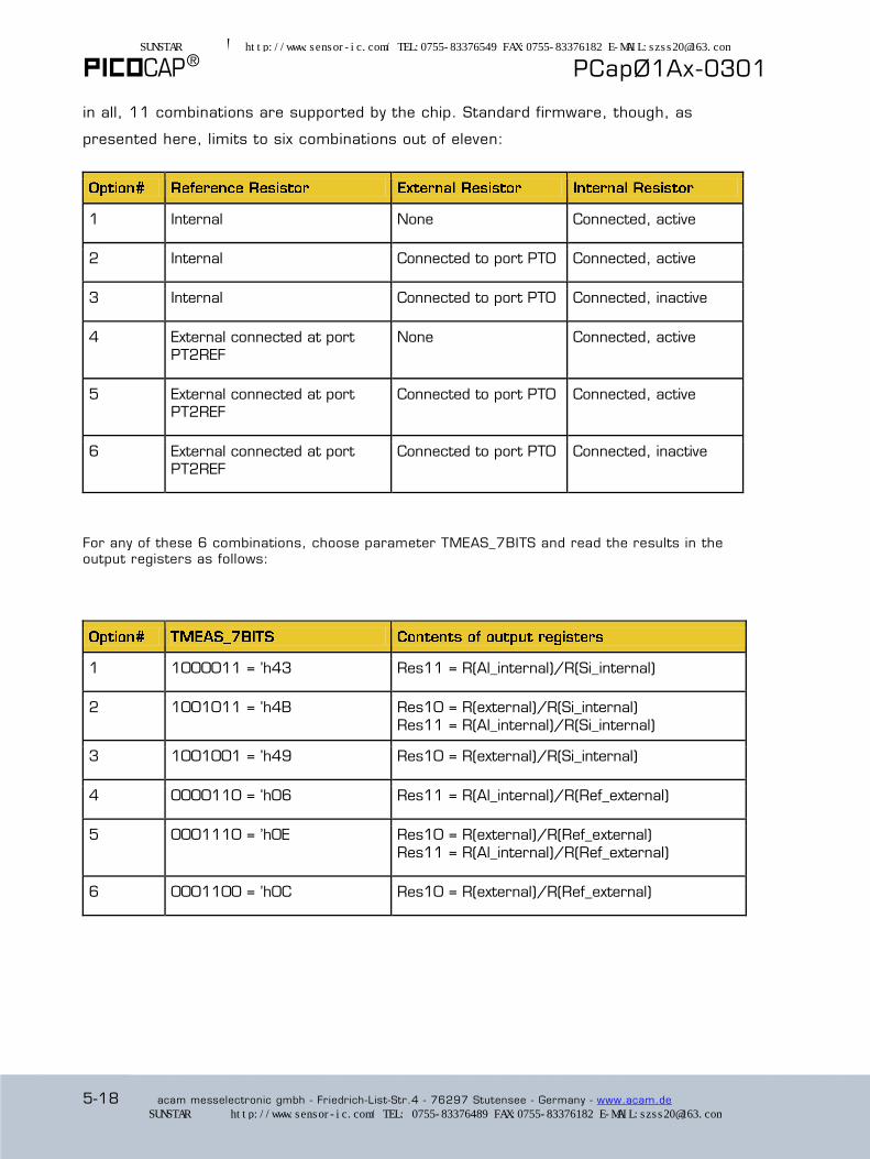
® PCapØ1Ax-0301
5-18 acam messelectronic gmbh - Friedrich-List-Str.4 - 76297 Stutensee - Germany - www.acam.de
in all, 11 combinations are supported by the chip. Standard firmware, though, as
presented here, limits to six combinations out of eleven:
1 Internal None Connected, active
2 Internal Connected to port PT0 Connected, active
3 Internal Connected to port PT0 Connected, inactive
4 External connected at port PT2REF
None Connected, active
5 External connected at port PT2REF
Connected to port PT0 Connected, active
6 External connected at port PT2REF
Connected to port PT0 Connected, inactive
For any of these 6 combinations, choose parameter TMEAS_7BITS and read the results in the output registers as follows:
1 1000011 = ’h43 Res11 = R(Al_internal)/R(Si_internal)
2 1001011 = ’h4B Res10 = R(external)/R(Si_internal)
Res11 = R(Al_internal)/R(Si_internal)
3 1001001 = ’h49 Res10 = R(external)/R(Si_internal)
4 0000110 = ’h06 Res11 = R(Al_internal)/R(Ref_external)
5 0001110 = ’h0E Res10 = R(external)/R(Ref_external)
Res11 = R(Al_internal)/R(Ref_external)
6 0001100 = ’h0C Res10 = R(external)/R(Ref_external)
SUNSTAR传感与控制 http://www.sensor-ic.com/ TEL:0755-83376549 FAX:0755-83376182 E-MAIL:[email protected]
SUNSTAR自动化 http://www.sensor-ic.com/ TEL: 0755-83376489 FAX:0755-83376182 E-MAIL:[email protected]
PCapØ1Ax-0301
acam messelectronic gmbh - Friedrich-List-Str.4 - 76297 Stutensee - Germany - www.acam.de 5-19
5.2.7 Comments on Register 8
It is recommended that you use the setting 0x800030 as mentioned to get started in
slave operation. Choose 0xA00030 for stand-alone applications. Please download
dedicated data sheet DB_PCap01_DSP_e.pdf (from www.acam.de)
The WATCHDOG parameter should be defined together with the firmware developer. When
using standard firmware (or any appropriate firmware containing “reset watchdog“
commands), the watchdog may be used and WATCHDOG_LENGTH = 3 may be a good
choice. Zero disables the watchdog.
Setting INT2PG allows the interrupt line to be outputted through the PG2 port (useful with
24-pin packages where there is no INTN pin). Using the interrupt technique is preferred to
polling the interface, because it minimizes the noise. — The low-current setting
(DSP_SPEED=3) might be incompatible with high speed measurements.
5.2.8 Comments on Register 9
Further details concerning the pulse code interface should be fixed in collaboration with
the firmware developer.
5.3 Read Registers
The read registers content is firmware specific, with the exception of Status. It depends
on the program that runs in the DSP. When no program is running, the result registers
will remain empty (except the status register). With the standard firmware 03.01.xx the
registers have the following content:
Address Name Content Description
0 Res 0 C0 LSB For reference only: normalized TDC value in LSB (see note below)
1 Res 1 C1/C0 Single C: ratio C1/C0
Differential C: ratio C1/C0
2 Res 2 C2/C0 or C3/C2 Single C: ratio C2/C0
Differential C: ratio C3/C2
3 Res 3 C3/C0 or C5/C4 Single C: ratio C3/C0
Differential (only grounded) C: ratio C5/C4
Fir
mw
are R
ela
ted
Fir
mw
are R
ela
ted
SUNSTAR传感与控制 http://www.sensor-ic.com/ TEL:0755-83376549 FAX:0755-83376182 E-MAIL:[email protected]
SUNSTAR自动化 http://www.sensor-ic.com/ TEL: 0755-83376489 FAX:0755-83376182 E-MAIL:[email protected]
® PCapØ1Ax-0301
5-20 acam messelectronic gmbh - Friedrich-List-Str.4 - 76297 Stutensee - Germany - www.acam.de
4 Res 4 C4/C0 or C7/C6 Single C: ratio C4/C0
Differential (only grounded) C: ratio C7/C6
5 Res 5 C5/C0 Single C only: ratio C5/C0
6 Res 6 C6/C0 Single C only: ratio C6/C0
7 Res 7 C7/C0 Single C only: ratio C7/C0
8 Status Status Status information (hardwired, not firmware dependent)
11 Res 8 not used
12 Res 9 not used
13 Res 10 R0/Rref Ratio Sensor 0 to reference
14 Res 11 R2/Rref Ratio Sensor 2 to reference
See figures 3-6 to 3-9 for a description of what C0 to C7 means. Concerning Res0, please
note that meaningful TDC values will be displayed only if C_AVRG=1 (or 0, meaning same).
Otherwise you will need to divide by the C_AVRG value. The evaluation kit performs this
without notice. After division, multiplying by the TDC bin width (typ. 22 - 25 picoseconds),
represents the discharge time encountered at C0.
Register Description in Detail:
23 22 21 20 19 18 17 16 15 14 13 12 11 10 9 8 7 6 5 4 3 2 1 0
Cx/Cy
integer fractional
Parameter Description Data range
C1/C0 etc. Capacitance ratios. Unsigned fixed-point numbers with 3 integer and 21 fractional digits.
0 to 7.9999995 resolution 0.477 ppm
SUNSTAR传感与控制 http://www.sensor-ic.com/ TEL:0755-83376549 FAX:0755-83376182 E-MAIL:[email protected]
SUNSTAR自动化 http://www.sensor-ic.com/ TEL: 0755-83376489 FAX:0755-83376182 E-MAIL:[email protected]
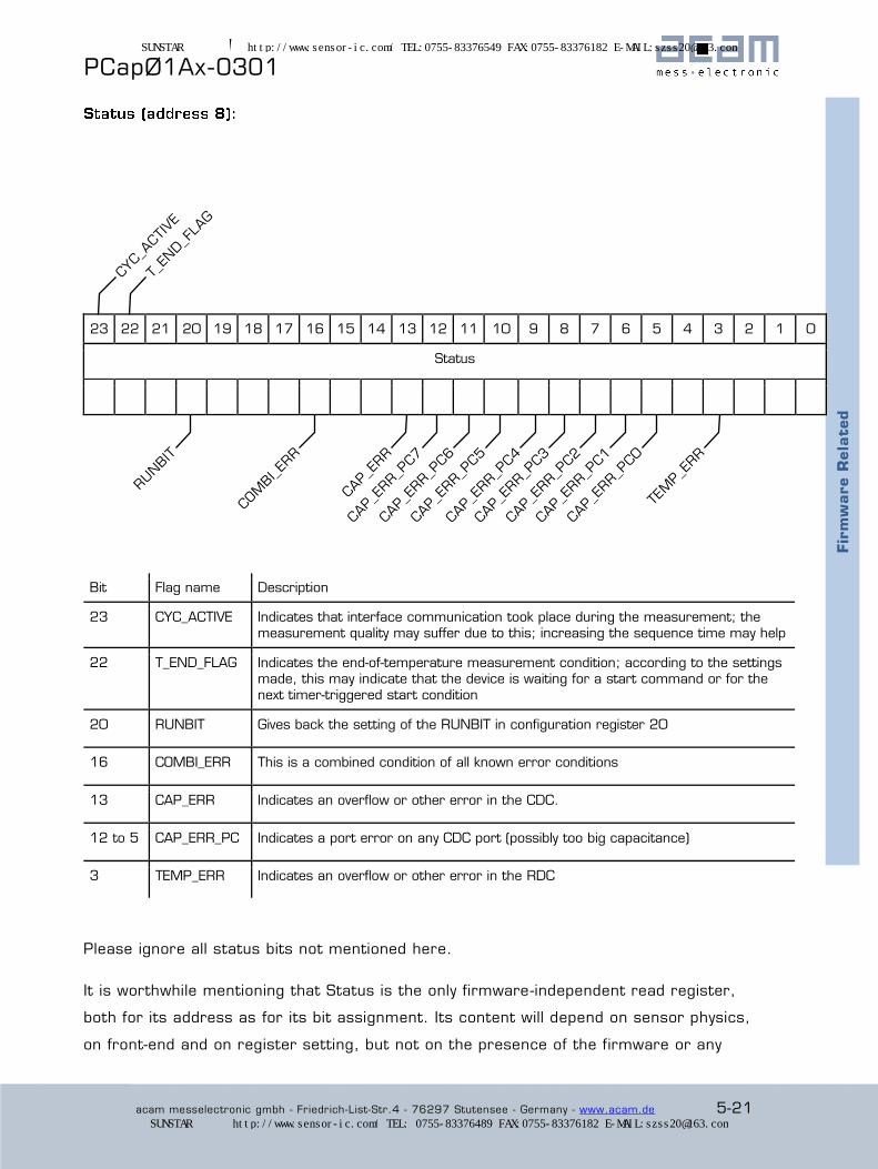
PCapØ1Ax-0301
acam messelectronic gmbh - Friedrich-List-Str.4 - 76297 Stutensee - Germany - www.acam.de 5-21
Fir
mw
are R
ela
ted
23 22 21 20 19 18 17 16 15 14 13 12 11 10 9 8 7 6 5 4 3 2 1 0
Status
Bit Flag name Description
23 CYC_ACTIVE Indicates that interface communication took place during the measurement; the measurement quality may suffer due to this; increasing the sequence time may help
22 T_END_FLAG Indicates the end-of-temperature measurement condition; according to the settings made, this may indicate that the device is waiting for a start command or for the next timer-triggered start condition
20 RUNBIT Gives back the setting of the RUNBIT in configuration register 20
16 COMBI_ERR This is a combined condition of all known error conditions
13 CAP_ERR Indicates an overflow or other error in the CDC.
12 to 5 CAP_ERR_PC Indicates a port error on any CDC port (possibly too big capacitance)
3 TEMP_ERR Indicates an overflow or other error in the RDC
Please ignore all status bits not mentioned here.
It is worthwhile mentioning that Status is the only firmware-independent read register,
both for its address as for its bit assignment. Its content will depend on sensor physics,
on front-end and on register setting, but not on the presence of the firmware or any
SUNSTAR传感与控制 http://www.sensor-ic.com/ TEL:0755-83376549 FAX:0755-83376182 E-MAIL:[email protected]
SUNSTAR自动化 http://www.sensor-ic.com/ TEL: 0755-83376489 FAX:0755-83376182 E-MAIL:[email protected]
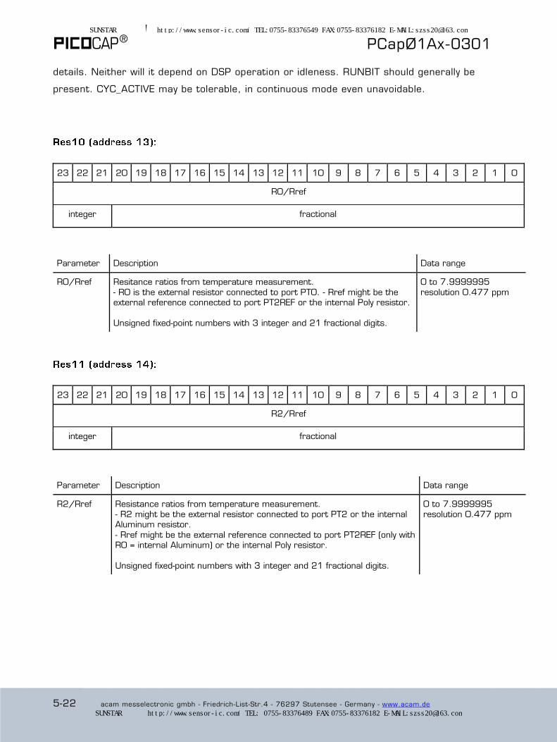
® PCapØ1Ax-0301
5-22 acam messelectronic gmbh - Friedrich-List-Str.4 - 76297 Stutensee - Germany - www.acam.de
details. Neither will it depend on DSP operation or idleness. RUNBIT should generally be
present. CYC_ACTIVE may be tolerable, in continuous mode even unavoidable.
23 22 21 20 19 18 17 16 15 14 13 12 11 10 9 8 7 6 5 4 3 2 1 0
R0/Rref
integer fractional
Parameter Description Data range
R0/Rref Resitance ratios from temperature measurement.
- R0 is the external resistor connected to port PT0. - Rref might be the external reference connected to port PT2REF or the internal Poly resistor.
Unsigned fixed-point numbers with 3 integer and 21 fractional digits.
0 to 7.9999995
resolution 0.477 ppm
23 22 21 20 19 18 17 16 15 14 13 12 11 10 9 8 7 6 5 4 3 2 1 0
R2/Rref
integer fractional
Parameter Description Data range
R2/Rref Resistance ratios from temperature measurement. - R2 might be the external resistor connected to port PT2 or the internal Aluminum resistor.
- Rref might be the external reference connected to port PT2REF (only with R0 = internal Aluminum) or the internal Poly resistor.
Unsigned fixed-point numbers with 3 integer and 21 fractional digits.
0 to 7.9999995 resolution 0.477 ppm
SUNSTAR传感与控制 http://www.sensor-ic.com/ TEL:0755-83376549 FAX:0755-83376182 E-MAIL:[email protected]
SUNSTAR自动化 http://www.sensor-ic.com/ TEL: 0755-83376489 FAX:0755-83376182 E-MAIL:[email protected]

PCapØ1Ax-0301
acam messelectronic gmbh - Friedrich-List-Str.4 - 76297 Stutensee - Germany - www.acam.de 6-1
6 DSP, Memory & Firmware
6.1 DSP Management and Programming ........................................................ 6-2
6.2 Memory Map ....................................................................................... 6-4
6.3 Memory Management ........................................................................... 6-4
6.4 OTP Firmware programming ................................................................... 6-5
6.5 Getting Started .................................................................................... 6-6
6.5.1 SRAM Firmware programming .......................................................... 6-6
6.5.2 Configuration, Example 1 ................................................................. 6-7
6.5.3 Configuration, Example 2 ................................................................. 6-9
6.5.4 Configuration, Example 3 ............................................................... 6-11
SUNSTAR传感与控制 http://www.sensor-ic.com/ TEL:0755-83376549 FAX:0755-83376182 E-MAIL:[email protected]
SUNSTAR自动化 http://www.sensor-ic.com/ TEL: 0755-83376489 FAX:0755-83376182 E-MAIL:[email protected]
® PCapØ1Ax-0301
6-2 acam messelectronic gmbh - Friedrich-List-Str.4 - 76297 Stutensee - Germany - www.acam.de
6.1 DSP Management and Programming
A digital signal processor (DSP) in Harvard architecture has been integrated. It is
programmable and responsible for the content of the read registers. The software, called
“firmware”, is either available ready-made from ACAM or can be user-written; Library
elements available. In the present datasheet, we describe the standard firmware 03.01.xx
as is provided by ACAM. Firmware 03.01 writes the compensated capacitance ratios and
the resistance ratios to the read registers, then performs the first -order linearization in
connection with the pulse-code outputs as described in section 4.2, but does no higher-
order linearization, filtering or any other data processing, though largely possible. This
Harvard DSP for 48 bit wide parallel data processing is coupled to a 48 x 48 bit RAM and
is internally clocked at approximately 100 MHz. The internal clock is stopped through a
firmware command, to save power. The DSP starts again upon a GPIO signal or an “end of
measurement run” condition.
The DSP is ACAM proprietary so as to cover low-power tasks as well as very high data
rates. It is programmed in Assembler (no high-level language is available). A user-friendly
assembler software with a graphical interface, helptext pop-ups together with sample code
sustain programming efforts. Subroutines can be coded.
The DSP signals a “data ready” state to an interrupt line. The interrupt may be picked
either from the INTN port or from GPIO (PG2). Using the interrupt technique has some
advantages with respect to noise and power consumption, also avoiding to produce
doublets (reading twice the same result).
SUNSTAR传感与控制 http://www.sensor-ic.com/ TEL:0755-83376549 FAX:0755-83376182 E-MAIL:[email protected]
SUNSTAR自动化 http://www.sensor-ic.com/ TEL: 0755-83376489 FAX:0755-83376182 E-MAIL:[email protected]
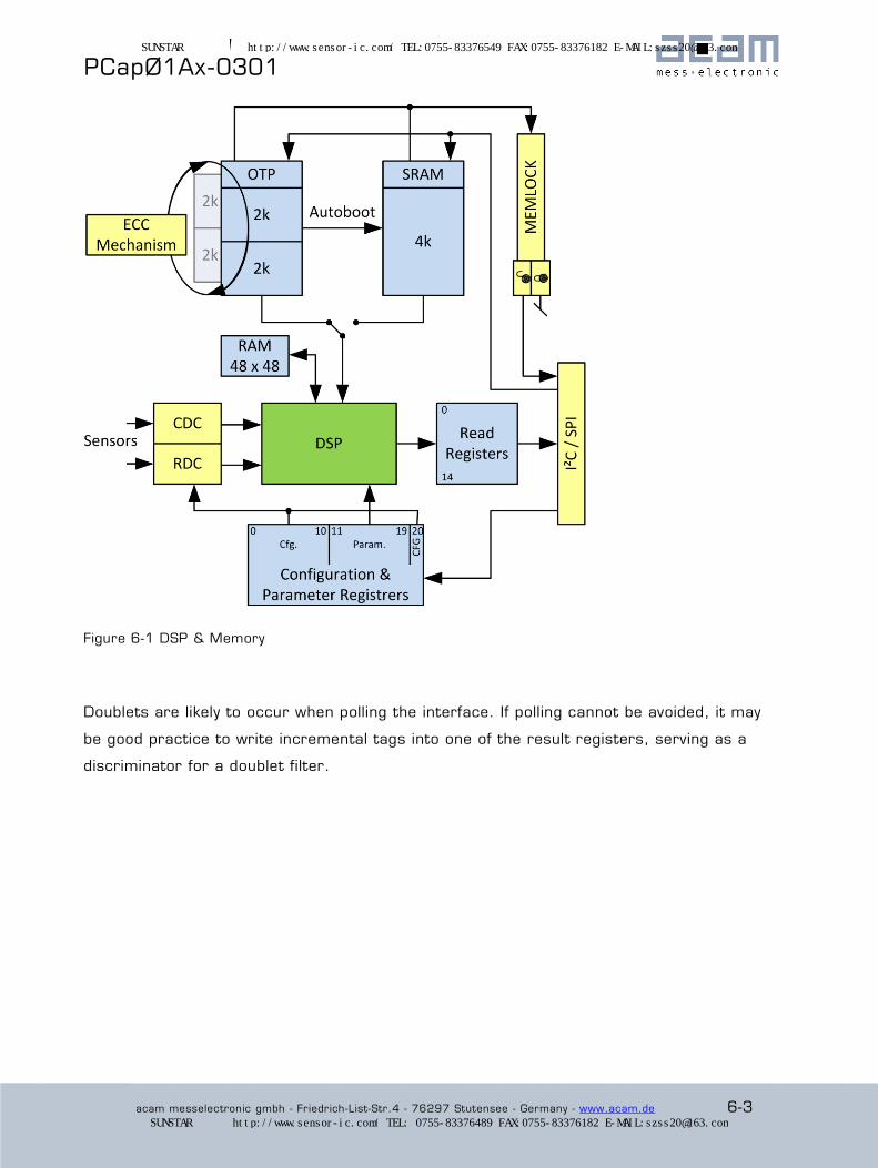
PCapØ1Ax-0301
acam messelectronic gmbh - Friedrich-List-Str.4 - 76297 Stutensee - Germany - www.acam.de 6-3
Figure 6-1 DSP & Memory
Doublets are likely to occur when polling the interface. If polling cannot be avoided, it may
be good practice to write incremental tags into one of the result registers, serving as a
discriminator for a doublet filter.
SUNSTAR传感与控制 http://www.sensor-ic.com/ TEL:0755-83376549 FAX:0755-83376182 E-MAIL:[email protected]
SUNSTAR自动化 http://www.sensor-ic.com/ TEL: 0755-83376489 FAX:0755-83376182 E-MAIL:[email protected]
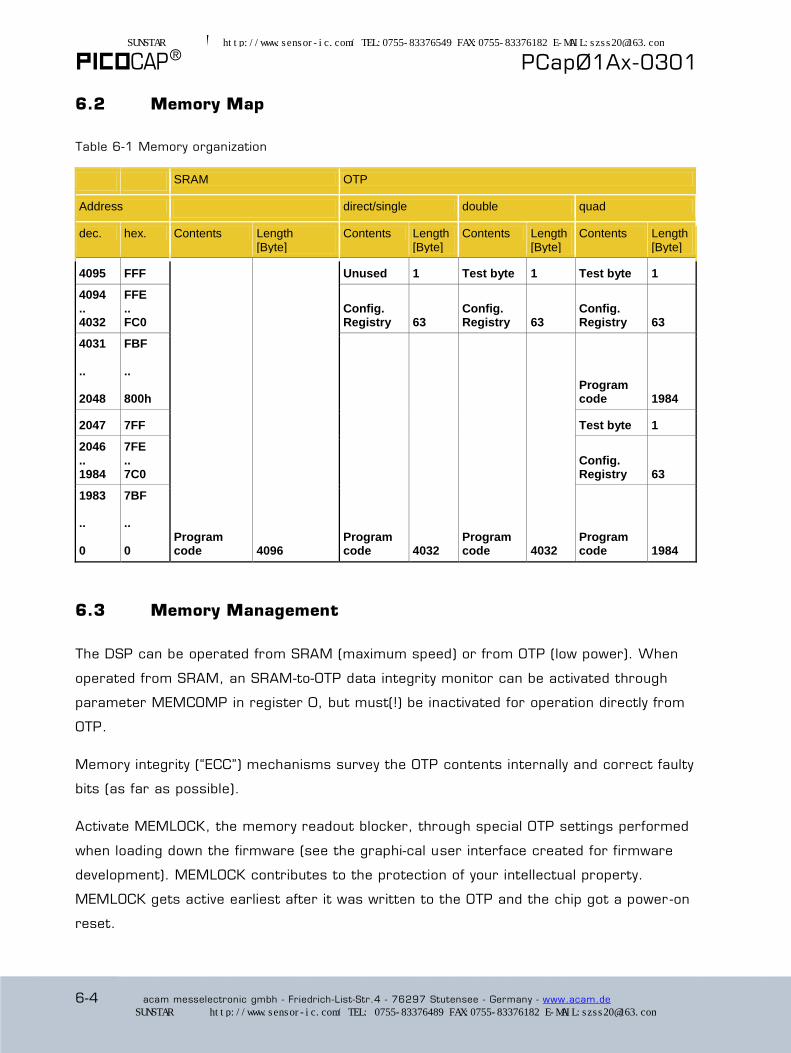
® PCapØ1Ax-0301
6-4 acam messelectronic gmbh - Friedrich-List-Str.4 - 76297 Stutensee - Germany - www.acam.de
6.2 Memory Map
Table 6-1 Memory organization
SRAM OTP
Address direct/single double quad
dec. hex. Contents Length [Byte]
Contents Length [Byte]
Contents Length [Byte]
Contents Length [Byte]
4095 FFF
Program code 4096
Unused 1 Test byte 1 Test byte 1 4094 .. 4032
FFE .. FC0
Config. Registry 63
Config. Registry 63
Config. Registry 63
4031 .. 2048
FBF .. 800h
Program code 4032
Program code 4032
Program code 1984
2047 7FF Test byte 1 2046 .. 1984
7FE .. 7C0
Config. Registry 63
1983 .. 0
7BF .. 0
Program code 1984
6.3 Memory Management
The DSP can be operated from SRAM (maximum speed) or from OTP (low power). When
operated from SRAM, an SRAM-to-OTP data integrity monitor can be activated through
parameter MEMCOMP in register 0, but must(!) be inactivated for operation directly from
OTP.
Memory integrity (“ECC”) mechanisms survey the OTP contents internally and correct faulty
bits (as far as possible).
Activate MEMLOCK, the memory readout blocker, through special OTP settings performed
when loading down the firmware (see the graphical user interface created for firmware
development). MEMLOCK contributes to the protection of your intellectual property.
MEMLOCK gets active earliest after it was written to the OTP and the chip got a power -on
reset.
SUNSTAR传感与控制 http://www.sensor-ic.com/ TEL:0755-83376549 FAX:0755-83376182 E-MAIL:[email protected]
SUNSTAR自动化 http://www.sensor-ic.com/ TEL: 0755-83376489 FAX:0755-83376182 E-MAIL:[email protected]

PCapØ1Ax-0301
acam messelectronic gmbh - Friedrich-List-Str.4 - 76297 Stutensee - Germany - www.acam.de 6-5
6.4 OTP Firmware programming
The PCap device is equipped with a 4 kB permanent program memory space, which is one-
time programmable, called the OTP memory. In fact, the OTP is total 8 kB in size but 4 kB
are used for ECC mechanism. If unprogrammed -by default- an OTP byte is h‘FF, not 00.
Once programmed to 0, an OTP bit cannot be shifted back to 1. Data retention is given for
10 years at 95°C. MEMLOCK is fourfold protected.
To program a bit in the OTP to Low or ‘0’, an external programming voltage of 6.5 V is necessary.
This voltage must be supplied to pin VPP_OTP during programming only, then removed, and pin
grounded. Hence it is impossible that an un-programmed bit be programmed to 0 spontaneously
during ordinary operation, when the VPP_OTP pin is grounded. The flowchart here shows the
sequence of steps to be performed to
program the firmware into the OTP:
It may be good practice to read the
firmware back and compare, at least
the first 960 bytes in the case of the
standard firmware. The read command
is similar to the write command with
'b001 for the leading bits:
24-bit COMMAND_READ_OTP = 'b001
+ 13-bit ADDRESS + 8-bit Firmware-byte
During the design process, if you find
some wrong bits in some of the bytes
you have read back, please (a) stop the
front end and (b) override register 0,
because the ECC_MODE parameter will
be critical for the readback process.
Useful settings are:
(a) Reg20 := 0 (runbit) and
(b) Reg0 := 0
or in op-code, ‘hD4000000 and
‘hC0000000.
SUNSTAR传感与控制 http://www.sensor-ic.com/ TEL:0755-83376549 FAX:0755-83376182 E-MAIL:[email protected]
SUNSTAR自动化 http://www.sensor-ic.com/ TEL: 0755-83376489 FAX:0755-83376182 E-MAIL:[email protected]

® PCapØ1Ax-0301
6-6 acam messelectronic gmbh - Friedrich-List-Str.4 - 76297 Stutensee - Germany - www.acam.de
6.5 Getting Started
6.5.1 SRAM Firmware programming
During software development, evaluation and also in many applications the user may want
to use the SRAM as program memory, not the OTP. For this purpose, send a power -up
reset, then write the firmware into SRAM. Op-codes “Write to SRAM“ and “Read SRAM“
grant access to arbitrary SRAM addresses. The following flowchart shows the first steps
after a power on Reset.
SUNSTAR传感与控制 http://www.sensor-ic.com/ TEL:0755-83376549 FAX:0755-83376182 E-MAIL:[email protected]
SUNSTAR自动化 http://www.sensor-ic.com/ TEL: 0755-83376489 FAX:0755-83376182 E-MAIL:[email protected]
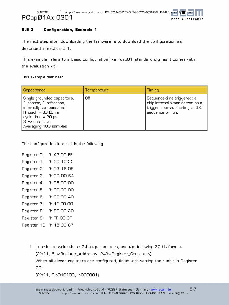
PCapØ1Ax-0301
acam messelectronic gmbh - Friedrich-List-Str.4 - 76297 Stutensee - Germany - www.acam.de 6-7
6.5.2 Configuration, Example 1
The next step after downloading the firmware is to download the configuration as
described in section 5.1.
This example refers to a basic configuration like Pcap01_standard.cfg (as it comes with
the evaluation kit).
This example features:
Capacitance Temperature Timing
Single grounded capacitors, 1 sensor, 1 reference,
internally compensated, R_disch = 30 kOhm cycle time = 20 µs
3 Hz data rate Averaging 100 samples
Off Sequence-time triggered: a chip-internal timer serves as a
trigger source, starting a CDC sequence or run.
The configuration in detail is the following:
Register 0: ’h 42 00 FF
Register 1: ’h 20 10 22
Register 2: ’h 03 16 0B
Register 3: ’h 0D 00 64
Register 4: ’h 08 00 00
Register 5: ’h 00 00 00
Register 6: ’h 00 00 40
Register 7: ’h 1F 00 00
Register 8: ’h 80 00 30
Register 9: ’h FF 00 0F
Register 10: ’h 18 00 87
1. In order to write these 24-bit parameters, use the following 32-bit format:
{2’b11, 6’b<Register_Address>, 24’b<Register_Contents>}
When all eleven registers are configured, finish with setting the runbit in Register
20:
{2’b11, 6’b010100, ’h000001}
SUNSTAR传感与控制 http://www.sensor-ic.com/ TEL:0755-83376549 FAX:0755-83376182 E-MAIL:[email protected]
SUNSTAR自动化 http://www.sensor-ic.com/ TEL: 0755-83376489 FAX:0755-83376182 E-MAIL:[email protected]

® PCapØ1Ax-0301
6-8 acam messelectronic gmbh - Friedrich-List-Str.4 - 76297 Stutensee - Germany - www.acam.de
2. Now the chip is ready, and measurement may begin. Send a partial reset (’h8A ),
but not a power-up reset!
3. Next, send a start command (’h8C).
4. Wait half a second, then read the status register (address 8) and results
(addresses 0 and 1). For reading 24-bit status and result registers, use the
following 32-bit format:
{2’b01, 6’b<Result_Address>, 24’b<Result_Data>}
It is expected to find status==’h100000 or ’h900000.
Res0 could be e.g. in the vicinity of 70000. This integer value, multiplied by 21
picoseconds (a typical time BIN size), gives an indication of the discharge time
measured. Thus, 70000 would correspond to 1.5 µs. Of course, this value depends
on the capacitances involved.
Res1 is expected to be in the range of 2,000,000 or ’h1FF2XX provided sensor
and reference are of same size. Res1 has the format of a fixed-point number with 3
integer digits and 21 fractional digits. So, dividing 2,000,000 by 2^21 gives a
result close to 1 for the ratio C1/C0.
Now, some words of caution, the 21 ps BIN size is just a typical value at room
temperature and at 3.0 volts. It will vary greatly over temperature, and it may be
batch-dependent. However, it is very constant on a sub-millisecond timescale. Given
the variability of the BIN size, we strongly recommend to make relative
measurements between some sensor and a reference; do not make absolute
measurements.
Fir
mw
are R
ela
ted
SUNSTAR传感与控制 http://www.sensor-ic.com/ TEL:0755-83376549 FAX:0755-83376182 E-MAIL:[email protected]
SUNSTAR自动化 http://www.sensor-ic.com/ TEL: 0755-83376489 FAX:0755-83376182 E-MAIL:[email protected]
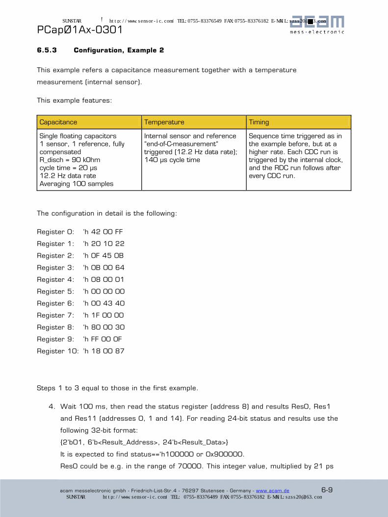
PCapØ1Ax-0301
acam messelectronic gmbh - Friedrich-List-Str.4 - 76297 Stutensee - Germany - www.acam.de 6-9
6.5.3 Configuration, Example 2
This example refers a capacitance measurement together with a temperature
measurement (internal sensor).
This example features:
Capacitance Temperature Timing
Single floating capacitors 1 sensor, 1 reference, fully
compensated R_disch = 90 kOhm
cycle time = 20 µs 12.2 Hz data rate
Averaging 100 samples
Internal sensor and reference “end-of-C-measurement“
triggered (12.2 Hz data rate); 140 µs cycle time
Sequence time triggered as in the example before, but at a
higher rate. Each CDC run is triggered by the internal clock,
and the RDC run follows after every CDC run.
The configuration in detail is the following:
Register 0: ’h 42 00 FF
Register 1: ’h 20 10 22
Register 2: ’h 0F 45 0B
Register 3: ’h 0B 00 64
Register 4: ’h 08 00 01
Register 5: ’h 00 00 00
Register 6: ’h 00 43 40
Register 7: ’h 1F 00 00
Register 8: ’h 80 00 30
Register 9: ’h FF 00 0F
Register 10: ’h 18 00 87
Steps 1 to 3 equal to those in the first example.
4. Wait 100 ms, then read the status register (address 8) and results Res0, Res1
and Res11 (addresses 0, 1 and 14). For reading 24-bit status and results use the
following 32-bit format:
{2’b01, 6’b<Result_Address>, 24’b<Result_Data>}
It is expected to find status==‘h100000 or 0x900000.
Res0 could be e.g. in the range of 70000. This integer value, multiplied by 21 ps
SUNSTAR传感与控制 http://www.sensor-ic.com/ TEL:0755-83376549 FAX:0755-83376182 E-MAIL:[email protected]
SUNSTAR自动化 http://www.sensor-ic.com/ TEL: 0755-83376489 FAX:0755-83376182 E-MAIL:[email protected]

® PCapØ1Ax-0301
6-10 acam messelectronic gmbh - Friedrich-List-Str.4 - 76297 Stutensee - Germany - www.acam.de
(BIN size) gives an indication of the discharge time measured. With 70000 we
would have a discharge time of 1.5 µs. Of course, this value depends on the
capacitors used.
Res1 is expected to be in the range of 2,000,000 or ‘h1FF2XX if the two
capacitors are of same size. Res0 has the format of a fixed point number with 3
integer digits and 21 fractional digits. So, dividing 2,000,000 by 2^21 gives a
result of about 1 for the ratio C1/C0.
Res11 gives the ratio of R(alu)/R(Si-poly) and should be something like 1,750,000.
Converted into a fractional number (division by 2^21) this is about 0.83, a typical
ratio at room temperature.
Fir
mw
are R
ela
ted
SUNSTAR传感与控制 http://www.sensor-ic.com/ TEL:0755-83376549 FAX:0755-83376182 E-MAIL:[email protected]
SUNSTAR自动化 http://www.sensor-ic.com/ TEL: 0755-83376489 FAX:0755-83376182 E-MAIL:[email protected]
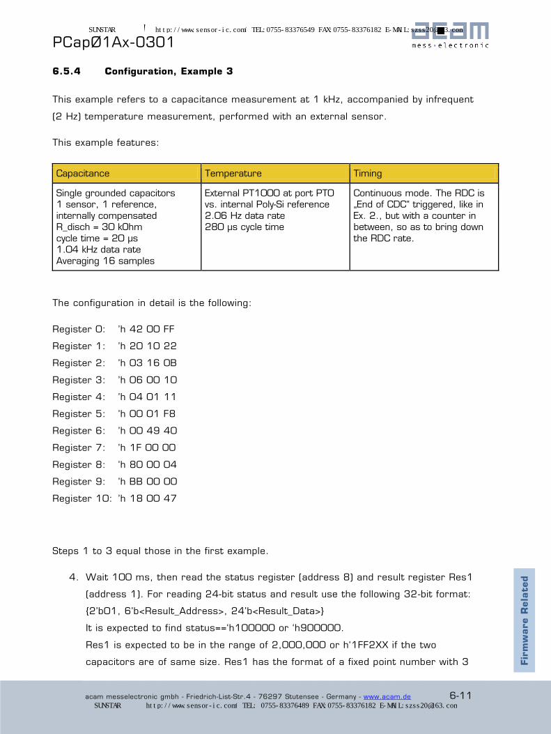
PCapØ1Ax-0301
acam messelectronic gmbh - Friedrich-List-Str.4 - 76297 Stutensee - Germany - www.acam.de 6-11
6.5.4 Configuration, Example 3
This example refers to a capacitance measurement at 1 kHz, accompanied by infrequent
(2 Hz) temperature measurement, performed with an external sensor.
This example features:
Capacitance Temperature Timing
Single grounded capacitors 1 sensor, 1 reference,
internally compensated R_disch = 30 kOhm
cycle time = 20 µs 1.04 kHz data rate
Averaging 16 samples
External PT1000 at port PT0 vs. internal Poly-Si reference
2.06 Hz data rate 280 µs cycle time
Continuous mode. The RDC is „End of CDC“ triggered, like in
Ex. 2., but with a counter in between, so as to bring down
the RDC rate.
The configuration in detail is the following:
Register 0: ’h 42 00 FF
Register 1: ’h 20 10 22
Register 2: ’h 03 16 0B
Register 3: ’h 06 00 10
Register 4: ’h 04 01 11
Register 5: ’h 00 01 F8
Register 6: ’h 00 49 40
Register 7: ’h 1F 00 00
Register 8: ’h 80 00 04
Register 9: ’h BB 00 00
Register 10: ’h 18 00 47
Steps 1 to 3 equal those in the first example.
4. Wait 100 ms, then read the status register (address 8) and result register Res1
(address 1). For reading 24-bit status and result use the following 32-bit format:
{2’b01, 6’b<Result_Address>, 24’b<Result_Data>}
It is expected to find status==‘h100000 or ‘h900000.
Res1 is expected to be in the range of 2,000,000 or h‘1FF2XX if the two
capacitors are of same size. Res1 has the format of a fixed point number with 3 Fir
mw
are R
ela
ted
SUNSTAR传感与控制 http://www.sensor-ic.com/ TEL:0755-83376549 FAX:0755-83376182 E-MAIL:[email protected]
SUNSTAR自动化 http://www.sensor-ic.com/ TEL: 0755-83376489 FAX:0755-83376182 E-MAIL:[email protected]

® PCapØ1Ax-0301
6-12 acam messelectronic gmbh - Friedrich-List-Str.4 - 76297 Stutensee - Germany - www.acam.de
integer digits and 21 fractional digits. So, dividing 2,000,000 by 2^21 gives a
value close to 1 for the ratio C1/C0.
Res11 gives the ratio of R(PT1000)/R(Si-poly) and should be something like
2,080,000. Converted into a fractional number (division by 2^21) this is about
0.992, a typical ratio at room temperature.
SUNSTAR传感与控制 http://www.sensor-ic.com/ TEL:0755-83376549 FAX:0755-83376182 E-MAIL:[email protected]
SUNSTAR自动化 http://www.sensor-ic.com/ TEL: 0755-83376489 FAX:0755-83376182 E-MAIL:[email protected]

PCapØ1Ax-0301
acam messelectronic gmbh - Friedrich-List-Str.4 - 76297 Stutensee - Germany - www.acam.de 7-1
7 Miscellaneous
7.1 Bug Report ......................................................................................... 7-2
7.1.1 I2C Bug ........................................................................................ 7-2
7.1.2 Spikes on IIC Interface ..................................................................... 7-3
7.1.3 SPI Limitation ................................................................................ 7-4
7.1.4 Power-up Reset Limitation ................................................................ 7-4
7.2 Document History ................................................................................ 7-5
SUNSTAR传感与控制 http://www.sensor-ic.com/ TEL:0755-83376549 FAX:0755-83376182 E-MAIL:[email protected]
SUNSTAR自动化 http://www.sensor-ic.com/ TEL: 0755-83376489 FAX:0755-83376182 E-MAIL:[email protected]
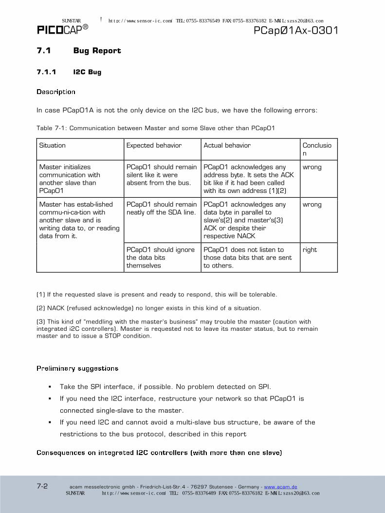
® PCapØ1Ax-0301
7-2 acam messelectronic gmbh - Friedrich-List-Str.4 - 76297 Stutensee - Germany - www.acam.de
7.1 Bug Report
7.1.1 I2C Bug
In case PCap01A is not the only device on the I2C bus, we have the following errors:
Table 7-1: Communication between Master and some Slave other than PCap01
Situation Expected behavior Actual behavior Conclusio
n
Master initializes
communication with another slave than
PCap01
PCap01 should remain
silent like it were absent from the bus.
PCap01 acknowledges any
address byte. It sets the ACK bit like if it had been called
with its own address (1)(2)
wrong
Master has established
communication with another slave and is
writing data to, or reading data from it.
PCap01 should remain
neatly off the SDA line.
PCap01 acknowledges any
data byte in parallel to slave's(2) and master's(3)
ACK or despite their respective NACK
wrong
PCap01 should ignore the data bits
themselves
PCap01 does not listen to those data bits that are sent
to others.
right
(1) If the requested slave is present and ready to respond, this will be tolerable.
(2) NACK (refused acknowledge) no longer exists in this kind of a situation.
(3) This kind of “meddling with the master‘s business“ may trouble the master (caution with integrated i2C controllers). Master is requested not to leave its master status, but to remain master and to issue a STOP condition.
Take the SPI interface, if possible. No problem detected on SPI.
If you need the I2C interface, restructure your network so that PCap01 is
connected single-slave to the master.
If you need I2C and cannot avoid a multi-slave bus structure, be aware of the
restrictions to the bus protocol, described in this report
SUNSTAR传感与控制 http://www.sensor-ic.com/ TEL:0755-83376549 FAX:0755-83376182 E-MAIL:[email protected]
SUNSTAR自动化 http://www.sensor-ic.com/ TEL: 0755-83376489 FAX:0755-83376182 E-MAIL:[email protected]
PCapØ1Ax-0301
acam messelectronic gmbh - Friedrich-List-Str.4 - 76297 Stutensee - Germany - www.acam.de 7-3
The use of hardwired I2C interfaces with multi -master capability may cause error during
read operations, because a master may go to Error due to some ACK bi t arriving within a
„read“ process (as the master alone should acknowledge data from slaves). This may
completely block the interface, unless the master has been instructed not to listen to the
line for detecting possible master-collision situations.
(Remark “master-collision situations“: In multi-master systems, two members may
incidentally become co-masters. This is part of the standard. Both co-masters listen to the
SDA line and become slave as soon as they detect a collision. This is what PCap01
provokes; all masters become slave, and the bus hangs.)
As write operations are possible, I2C expanders may be used to interface PCap01 in multi -
slave systems.
You are recommended to simplify and to modify the interface protocol:
The most basic subset of the I2C standard will be best.
Multi-master, arbitration and the like should be skipped.
Master must ignore any ACK bits set in competition with its own ACKs or NACKs.
Master cannot rely on any ACK bits issued by other slaves than PCap01. ACK bits
are likely to come from PCap01. Pay attention to this, especially during debugging
and for error-handling.
Some work-around may be necessary in order to check for the presence and
readiness of a slave, which standardwise would be signaled through an ACK.
You cannot use NACK bits. In particular, NACK cannot be used to signal “end of
transfer“ to a slave. You must abort by a repeated -start or by a stop condition.
If possible, use an I2C expander in multi-slave applications.
7.1.2 Spikes on IIC Interface
It was observed that spikes on the IIC lines, especially SDA to SCL crosstalk is causing a
bit stream of ones („1”). This way, it appears in the data like a „freezing“ of values, e.g.
the temperature value. The background of this error is that the spike is seen by PCap01
as an acknowledge bit (ACK) and therefore active sending is stopped. The master still
sends clock cycles and by means of the pull -up a series of „1“ is generated.
SUNSTAR传感与控制 http://www.sensor-ic.com/ TEL:0755-83376549 FAX:0755-83376182 E-MAIL:[email protected]
SUNSTAR自动化 http://www.sensor-ic.com/ TEL: 0755-83376489 FAX:0755-83376182 E-MAIL:[email protected]
® PCapØ1Ax-0301
7-4 acam messelectronic gmbh - Friedrich-List-Str.4 - 76297 Stutensee - Germany - www.acam.de
The error occurs usually when a typical bit pattern is proceeding, which is XXXX_0001 or
XXXX_0101. The following byte is then 1111_1111.
Workaround: the spike should be filtered at the inputs of PCap01. This can be achieved in
two ways:
1.) Insert a small capacitance, e.g. 10 pF from SCL line to either GND or VDD. It should
be placed close to the chip.
2.) Insert a series resistor of 100 Ohms in the SDA line. Again, place it close to the chip.
7.1.3 SPI Limitation
In some applications, several components are wired to the same SPI bus and are
individually ad-dressed through the chip-select (SSN) line. For this to work, any non-
addressed component, seeing SSN ‘high‘, must set its MISO port to high impedance. No
high-impedance state existing on MISO port inside PCap01.
Avoid sharing MISO, or insert an (inexpensive) external single-gate tri-state
buffer between PCap‘s MISO port and the MISO line.
7.1.4 Power-up Reset Limitation
In case of shorttime power down, the PCap01 does not safely detect the power -down
status. In consequence, it may happen that the chip does not run a power-up procedure
but hangs.
a) Operated as a slave, upon power-down, the PCap01A needs a dedicated
software power-up reset via the interface by the microcontroller.
b) Operated stand-alone, the PCap01A may need an additional external power-up circuit.
However, if power consumption is not critical, a simple 11 kOhm resistor between
BUFFCAP and GROUND is believed to be sufficient as a workaround, for any power
shutdown lasting 100 ms or more.
SUNSTAR传感与控制 http://www.sensor-ic.com/ TEL:0755-83376549 FAX:0755-83376182 E-MAIL:[email protected]
SUNSTAR自动化 http://www.sensor-ic.com/ TEL: 0755-83376489 FAX:0755-83376182 E-MAIL:[email protected]

PCapØ1Ax-0301
acam messelectronic gmbh - Friedrich-List-Str.4 - 76297 Stutensee - Germany - www.acam.de 7-5
7.2 Document History
04.08.2010 First release
11.04.2012 Two dozen minor corrections and amendments, throughout the chapters;
separation between hardware and software aspects (blue stripe in margin)
16.01.2013 Corrections and amendments in the chapters 2, 5 and 7
15.07.2013 version 0.6 released with following changes:
- in register 2, parameter C_GRD_FLOAT replaced by CMEAS_SCHEME
- supplement in the read register overview in chapter 5.3
- calculation of CMEAS_CYTIME fixed.
SUNSTAR传感与控制 http://www.sensor-ic.com/ TEL:0755-83376549 FAX:0755-83376182 E-MAIL:[email protected]
SUNSTAR自动化 http://www.sensor-ic.com/ TEL: 0755-83376489 FAX:0755-83376182 E-MAIL:[email protected]

acam-messelectronic gmbh
Friedrich-List-Straße 4
76297 Stutensee-Blankenloch
Germany
Phone +49 7244 7419 – 0
Fax +49 7244 7419 – 29
E-Mail [email protected]
www.acam.de
SUNSTAR传感与控制 http://www.sensor-ic.com/ TEL:0755-83376549 FAX:0755-83376182 E-MAIL:[email protected]
SUNSTAR自动化 http://www.sensor-ic.com/ TEL: 0755-83376489 FAX:0755-83376182 E-MAIL:[email protected]