


Languages
Pages
Legal


ISSN 0104-6500Journal of the Brazilian Computer Society, 2009; 15(2):3-18.
*e-mail: [email protected]
Volume sculpting based on geometric tools
Rafael Huff, Roberto Silveira da Rosa Jr., Luciana Nedel, Carla Maria Dal Sasso Freitas*
Institute of Informatics, Federal University of Rio Grande do Sul,
91501-970, Porto Alegre, RS, Brazil
Received: October 22, 2008; Accepted: June 23, 2009
Abstract: The analysis of volumetric datasets is the main concern in many areas ranging from geophysics to biomedical
sciences. The direct visualization of these data plays an important role in this scenario, and in spite of developments in volume
visualization techniques, interacting with large datasets still demands research efforts due to perceptual and performance
issues. There is a need of interactive sculpting tools which can provide an intuitive way to examine and explore inner parts
of the datasets, as well as to fill missing data for specific purposes. In this paper we report the development of interactive,
intuitive and easy-to-use sculpting tools, which specify regions within the volume to be discarded from rendering, thus
allowing inspection of the volume interior, and to be filled with material to build virtual structures in the volume. Interactive
rates for these sculpting tools were obtained by running special fragment programs on the graphics hardware. The tools were
implemented using two interaction metaphors (virtual pointer and virtual hand) and following different approaches in terms
of devices and single versus two-handed interaction. We report the evaluation of these approaches in detail and concluded
that the use of two different devices together presents a better performance and are preferred by users. Moreover, the use of
virtual hand interaction provided better results than using the virtual pointer during the tests.
Keywords: volume sculpting, virtual pointer, virtual hand, volumetric data, volume rendering.
1. Introduction
Several applications involve the generation, explora-
tion and analysis of volumetric datasets. For years, the
requirements of medical applications have pushed the state-
of-the-art in visualization and interaction techniques, mainly
driven by accuracy and computational time constraints.
Direct visualization of volume data, or volume rendering,
has been playing an important role in this scenario allowing
to obtain helpful images through the use of a variety of asso-
ciated techniques: from colors and transparency29, 19, 18 to
enhance or fade away portions of the dataset to techniques
used by scientific illustrators to improve perception of some
structures10, 3; from geometric clipping planes to allow the
observation of arbitrary slices of the dataset22, 30 to volume
deformation techniques23, 7 to provide ways of browsing the
volume.
In direct volume rendering, transfer functions29 provide a
mapping between data values and image visual properties.
However, although there have been a considerable research
effort on developing these techniques, the generation of
informative renderings from a dataset is still challenging. The
specification of efficient transfer functions11 to segment some
datasets is sometimes impracticable, even with recent frame-
works8, 41, requiring non-automatic segmentation tools based
on interactive manipulation of the volume data. For example,
it is difficult to isolate some inner structures of brain CT scans
due to the resemblance of their density values with others in
the volume, and frequently an expert is required to manually
separate these structures using geometric tools.
In order to assist users to perform this task, volume clip-
ping and deformation tools have been developed30, 38, 23, 4.
However, especially in clipping tools, most of the research
is dedicated to improve performance in order to guarantee
interactive rates, and few of them are concerned with the
interactivity itself. Therefore the objective of our work is to
develop intuitive, easy-to-use and efficient clipping tools
(Figure 1), generic and simple enough to be used in volu-
metric datasets from different fields. In order to guarantee
that, we performed many test with users to evaluate the
interaction with the tools.
The operations performed to clip volumes, removing
material resembling a manual modeling task, have been
referred as volume sculpting37. More recently, Islam et al.17
coined the expression volume splitting as a general form of
referring to both deformation and clipping operations. They
base their work on constructive volume geometry, which is a
nice concept that provides the basis for an important opera-
tion in many applications, the insertion of material into parts
of the volume. For example, in the volume shown in Figure 2a
part of the jaw is missing due to trauma, and the insertion
of material in those voxels can be used as an initial step for
designing a prosthesis (Figure 2b).
Traditional volume sculpting is basically a selection task,
where the voxels inside a volume are first selected (using
some tool like the carving tools in Wang and Kaufman37) and
then deleted. For adding a structure to empty voxels, in this
modeling process, the same actions could be done: selecting
voxels to fill them with a specified material.

Journal of the Brazilian Computer Society4 Huff R, Rosa-Jr RS, Nedel LP and Freitas CMDS
The selection of these voxels can be made using many
different techniques represented by two basic metaphors33:
virtual pointer and virtual hand. In the virtual pointer meta-
phor, the user points at the object of interest using some
cursor even if he is far away from the object. Techniques
based on the virtual pointer metaphor are usually easy to
learn and use because they are based on 2D interaction, i.e.,
in tasks with two degrees-of-freedom (DOFs), and nearly
everybody is familiar with 2D input devices and applica-
tions. However, in 3D interaction techniques based on the
virtual hand metaphor, the continuity between the real and
virtual world is enhanced, because the cursor has six DOFs
and allows the user to “touch” and manipulate virtually the
object of interest.
In an earlier paper16 we described three sculpting tools
following a 3D interaction paradigm – the virtual hand inter-
action technique – to allow real-time volume sculpting in
an efficient and comfortable way while using commodity
PC workstations. Our 3D tools are called: 3D eraser, 3D digger
and 3D clipper (Figures 1a-c). Real-time response rates have
been achieved by running the sculpting tools and volume
rendering on GPU. In that work we were interested in
measuring user’s performance using different devices
(conventional and 3D mouse) as well as one and two hands.
The present paper reports a large extension of our
previous work comprising several aspects. We implemented
the three sculpting tools following also a 2D interaction
paradigm, using the virtual pointer interaction technique
(Figures 1d-f). The efficiency of the interaction was measured
regarding different ways of controlling the tools. Like in the
previous work, we implemented the tools controlled by a
conventional 2D mouse as well as a 3D mouse. As a result of
experiments with users, we also designed and implemented
two additional sculpting operators, for inserting material into
the volume, thus fulfilling the lack we found in the current
scenario regarding volume manipulation. These operators are
mirror and filler, which we classify as filling operators. They
were assessed by exploring alternatives in a usage scenario.
The remainder of the paper is structured as follows. In
the next section, we review some relevant previous work. We
then present the sculpting tools (Section 3) including details
of their implementation (Section 4). The use of the tools by
experimental users is reported and discussed (Section 5).
The filling operators are described and their evaluation is
reported in Sections 6 and 7, respectively). Conclusions and
future work are drawn in the last section.
2. Related Work
Although volumetric visualization techniques have been
proposed since the 80’s, only in the last years the advances
in commodity graphics hardware allowed texture-based
volume rendering to achieve satisfying image quality with
better performance than software-based methods34, 19.
Interacting with volumes to expose inner structures
through clipping tools started with the use of clipping
planes22, 14, 28. Wang and Kaufman37 pioneered the use of
carving and sawing tools, with voxelized geometries as tools
and explicit set operators between volume data and the tools.
Along the years, different clipping approaches have been
considered in scientific visualization30, 39.
Van Gelder and Kim14 used clipping planes to specify the
boundaries of the clipping region in texture-based volume
rendering while Westermann and Ertl40 introduced the
concept of clipping geometries by means of stencil buffer
operations. Later on, Pfister et al.28 proposed the VolumePro
hardware architecture with cropping and cutting planes
features for clipping the volume.
Weiskopf et al.38 proposed clipping tests using per-
fragment operations on the graphics hardware to maintain
high rendering speed. They propose a depth-based clipping
technique that analyzes the depth structure of the clipping
geometry to decide which parts of the volume have to be
clipped (a similar approach is used by Diepstraten et al.9).
They also propose a clipping tool that uses a voxelized clip-
ping object to identify clipped regions. In this tool, a texture
buffer stores visibility information, and it is used as a mask
that indicates if each voxel will contribute to the final image.
This clipping texture is obtained by the voxelized geometry
of clipping tools on the CPU. Scale, rotation and translation
operations of the clipping object are allowed by adapting the
texture coordinates of the clipping texture. The “voxelized
a b c
d e f
a
Figure 2. a) Part of the jaw (left side) is missing due to trauma; and
b) Voxels filled with material to model a prosthesis.
Figure 1. Volumetric Sculpting Tools: a) 3D Eraser, b) 3D Digger,
c) 3D Clipper, d) 2D Eraser, e) 2D Digger and f) 2D Clipper.
b

5Volume sculpting based on geometric tools2009; 15(2)
clipping object” paradigm is also exploited in our work but
the geometries of our tools are voxelized on the GPU.
Volume deformation tools, as proposed by McGuffin
et al.23, have the advantage of showing inner structures
surrounded by its context. However, as presented in that
work, they do not serve to the purpose of actually segmenting
parts of interest in the volume since they are devoted mainly
to browsing purposes. They provide a way to explore
semantic layers in the dataset (i.e. previously segmented
data), by spreading voxels in a given direction. In the present
work, regarding clipping, we are concerned with the actual
isolation of voxels, removing from the view those that are not
of interest.
VolumeShop, proposed by Bruckner and Gröller4, is a
volume illustration system based on sculpting tools: cutaway
and ghost tools use opacity assignments to remove occluding
regions thus providing visual inspection of inner features.
This is somehow similar to our approach, the difference
relying on the way we select the regions to be eliminated from
(or added to) the volume. They cast a ray from a point clicked
on a screen into the volume. At the first voxel crossed by this
ray, a volumetric brush centered on the voxel can either add
to or erase details from the selection volume for every voxel
within the brush bounding box.
Recently, Chen et al.6 also presented a framework of inter-
active GPU-based tools for real-time volume manipulation
and segmentation. These tools were developed using a point-
based strategy for sculpting volumes and removing occluding
materials. Some operations of these tools were inspired by
medical procedures like drilling, peeling and lasering, and
others provided basic operations like cutting and pasting.
They also implemented a system for region-growing segmen-
tation and multiple seeds planting with sketches.
The research briefly reviewed above proposed new
techniques to improve the performance of sculpting tools,
while guaranteeing interactive frame rates. However, the
authors do not exploit the advantages of different interac-
tion metaphors and devices, although sculpting applications
for modeling purposes have used different devices, such as
conventional 2D mouse37, 3D mouse13, and even both devices
at the same time27.
In our previous work16, we developed three sculpting
tools (3D eraser, 3D digger and 3D clipper) following the
virtual hand interaction technique, using different devices
(conventional and 3D mouse) as well as one and two hands.
Experiments showed that the conventional 2D mouse
yielded better performance in time completion for the eraser
and digger tools, but error rate was lower when using the
3D mouse for controlling the sculpting tool in two-handed
interaction. User’s preference obtained through a question-
naire showed that subjects preferred to use the 2D mouse to
control the sculpting tool and the 3D mouse to control the
volume.
Even though interaction techniques could be classified
into just two basic metaphors – virtual pointer and virtual
hand – several different techniques should be considered to
implement these metaphors. For the virtual pointer meta-
phor, techniques can differ from each other in the shape of
the pointer, the definition of its direction and the methods
of disambiguating the object the user wants to select. The
most common example is the ray-casting technique24 and
its variations: ray-casting with fishing reel1, spotlight25, aper-
ture selection12, and image plane31. Regarding the virtual hand
based techniques, the choice of input devices and mappings
between the position and orientation of real and virtual
hands are the differentiation. The classic virtual hand was
discussed by many authors33, 36, 26 and some extensions have
been presented32, 1, 24.
Moreover, two-handed input has often been viewed as
a technique to improve the efficiency of human-computer
interaction, by enabling the user to perform two sub-tasks
in parallel5, helping users to better perceive a 3D environ-
ment because it takes advantage of people’s innate ability
of knowing precisely where their hands are relative to each
other15, 35. Leganchuck et al.20 also noticed that using both
hands in an application brings cognitive and manual advan-
tages and their work provided a complimentary perspective,
exploring the potential benefits into everyday applications.
In the present work we exploit all these alternatives to
enhance interactivity in volume sculpting while maintaining
high-quality and real-time rendering by employing graphics
hardware programming.
3. Tools for Volume Sculpting
Aiming at an intuitive interface for sculpting volumes, we
designed a set of tools based on interaction techniques using
both the virtual pointer and the virtual hand metaphors.
Since selection using virtual pointer is essentially a
2D operation2, we developed a set of 2D sculpting tools using
the “painting” paradigm present in most ordinary image-
editing applications, where the user controls virtual pens,
brushes, and other free-hand artistic instruments to paint
or erase on a virtual canvas. These tools are called 2D eraser,
2D digger and 2D clipper (Figures 3a-c), and implement basic
sculpting operations, which are used to perform complex
cutting, clipping and cropping tasks. Even though the user is
sculpting a 3D volume, using these 2D tools is like editing a
common 2D image.
The three-dimensional versions of the same tools (3D eraser,
3D digger and 3D clipper, see Figures 3d-f), reported in Huff
et al.16, use the virtual hand metaphor. In these versions, the
virtual hand is represented as different cursors, depending on
the tool in use, and their shapes mimic the operation of the 2D
tools. The following sections describe the conceptual design of
the 2D and 3D tools as well as their implementation.
3.1. Eraser tools
The 2D Eraser tool (Figure 1d) uses the Aperture Selection
technique12, a modification of the ray-casting technique. The
cursor is a circle aligned with the view plane and the origin
of the virtual pointer is set to the location of the user’s point
of view, as shown in Figure 3a.

Journal of the Brazilian Computer Society6 Huff R, Rosa-Jr RS, Nedel LP and Freitas CMDS
The direction vector of this pointer, named line of sight, is
the vector from the point of view to the center of the cursor.
The size of the cursor r is previously established by the user
and the position P is also specified by the user through the
selection of a pixel on the screen. The size and 2D position
of the cursor, together with its distance to the point of view,
determine the selection volume.
When the 2D Eraser tool is applied to the volume, the
position of each voxel is tested against the selection volume,
and all voxels inside this volume are removed. The test is
performed by (perspective) projecting the center of each
voxel onto the view plane. If the 2D Euclidean distance d of
the projected voxel V to the center of the cursor P is smaller
than the radius r of the cursor, the voxel is inside the volume
(Figure 3a).
Observing Figure 3a, it is possible to notice that the
2D Eraser Tool can be interpreted in 3D as a cone (due to
the perspective projection during the volume visualiza-
tion process) perpendicular to the view plane with the apex
located at the user’s point of view and the base at the infinity.
The viewing angle is the opening angle of the cone, consid-
ering a cross section through the apex point and the center of
the cursor.
Using an orthographic projection, the resulting shape is
a cylinder, which makes more sense when the virtual hand
metaphor is used for controlling the tool, since the cursor
should be independent of viewing parameters. Detaching
the cylinder from the point of view of the user provides the
possibility of freely rotate and translating it. Our 3D Eraser
tool (Figure 1a) was conceived in this way (Figure 3d).
The parameters used for testing a voxel against the volu-
metric region defined by the cylinder (3D Eraser tool) are
similar to those employed for the 2D Eraser tool: a projec-
tion plane, a 2D point P on this plane and the radius r of the
cylinder. It should be noticed that in the 3D Eraser, the cursor
is independent of the viewing parameters, and thus the
projection and the view plane are independent too, as can be
observed in Figure 3d). When the cursor is rotated and trans-
lated, these transformations are applied to this projection
plane. The selection of a voxel for elimination is done by first
orthogonally projecting its center into the projection plane.
For each projected center, a distance to P is computed (called
projected distance d of a voxel). d is a 2D Euclidean distance
since it is calculated on the projection plane (Figure 3d).
Following, every voxel with d < r is removed.
3.2. Digger tools
Often, during volume sculpting, instead of erasing it all the
way through with the Eraser tools, the need is digging a hole
in the volume. Here, this is accomplished by the Digger tools.
The 2D Digger tool (Figure 1e) considers for removal the
same voxels of the 2D Eraser tool, i.e., inside a circle, but only
those within a given depth from the first point on the volume
boundary along the line of sight (Figure 3b). The cursor of
this tool is also a circle that can be translated (by the user) on
the view plane, and its depth is calculated from the cursor
radius r (also defined by the user), the surface distance ds
and the view plane distance dv to the point of view, as given
by Equation 1.
dsdepth = * r
dv (1)
When the 2D Digger tool is applied, it is like an object
hitting the surface of the volume and eliminating every voxel
inside a region delimited by its depth. This is obtained by
selecting the first voxel (on the surface of the volume) inter-
cepted by the line of sight and calculating the 3D Euclidean
distance d from it to every other voxel v. All the voxels within
a distance smaller than the depth of the tool are erased. The
a b c
d e f
r
r
r
P
rP
View plane
View plane
Point ofview
Point ofview
Point ofview
Point ofview
Projection plane
Cursor
Cursor
Cursor
View planeCursor
d
d
d
d
d
v
v
v
d
v
v
v
Mask
Mask Mask
Mask Mask
Line of sight
Line of sight Point of
view
Point ofview
Depht
dvds
p1 p2
Cursor
PP
Cursor
Mask
Figure 3. 2D Tools: a) Eraser, b) Digger, and c) Clipper. 3D Tools: d) Eraser, e) Digger, and f) Clipper.

7Volume sculpting based on geometric tools2009; 15(2)
selection region associated to the 2D Digger tool can be inter-
preted as a semi-sphere with the center located on the surface
of the volume. The size and position of this semi-sphere are
constrained by viewing parameters: its size varies according
to Equation 1, and the position is determined by the intersec-
tion between the line of sight and the volume surface.
As for the 3D Digger tool, the virtual hand cursor is actu-
ally a sphere detached from the view plane. This means that
the center of the sphere does not have to be located on the
volume surface anymore, and can be placed anywhere in
the volume, being freely controlled by the user (Figure 1b).
Figure 3e shows how it was designed. The sphere has radius
r and center position P both specified by the user, and the
selection of a voxel for removal is done by first calculating
the 3D Euclidean distance d of the voxel’s center to P. If this
distance is smaller than r, the voxel is removed.
3.3. Clipper tools
Differently from the 2D Eraser and Digger tools, the
cursor of the 2D Clipper tool (Figure 1f) is represented by a
line segment on the view plane (Figure 3c), defined by two
points selected by the user on the screen. This line divides
the whole image that the user is observing, in order to delete
part of the volume.
The 2D Clipper defines a convex region that lies inside
the 3D original volume following a carving approach. This is
accomplished by calculating a clipping plane through three
points: the point of view and the two points specified by the
user on the screen. The selection of a voxel for elimination is
done by calculating the smallest distance of its center to that
plane. This (signed) distance is calculated by a dot product
between voxel coordinates and plane coefficients. The voxel
is removed if the distance is negative. Even though a clip-
ping plane and 3D distances are used, due to the perspective
projection, the user visualizes it as a 2D operation.
As for the virtual hand metaphor (Figure 1c), instead of a
line, the user manipulates a square (Figure 3f) that represents
the cutting plane. The square can be freely translated and
rotated, and, differently from the 2D Clipper tool, it is not
attached to the user’s point of view. When this cutting plane
is applied for removing voxels, it slices the current volume
and creates a shape with one additional face. This process
can be repeated as long as needed, and is performed using
the dot product, like for the 2D Clipper tool.
4. Tools Implementation
All the six sculpting tools presented in the previous
section (2D and 3D Eraser, Digger and Clipper) were inte-
grated in a texture-based volume rendering system based on
the paradigm proposed by Weiskopf et al.38. Figure 4 shows
the structure of the system using a clipping plane as an
example of volume sculpting tool.
The first stage (initialization) is the processing of the volu-
metric dataset and its storage as a 3D texture in the GPU.
During this process, if required, a pre-classification according
to a transfer function11 or calculations of scalar values and
gradients for volume shading39 can be used.
The actual sculpting of the volume is accomplished
through special fragment shaders that run on the GPU, and
use the tool geometry to eliminate voxels. This is accom-
plished by the stages update and drawing.
With few parameters, the geometries of our tools are
voxelized on the GPU by specialized fragment shaders,
differently from the work developed by Weiskopf et al.38,
where tools are voxelized on the CPU.
Updates are requested when the user interacts with the
system, either changing viewing parameters or sculpting the
volume. Viewing changes are issued at camera manipula-
tion, but sculpting can be produced by any tool. Since the
tools are voxelized on the GPU, the active clipping tool can
be changed interactively, resulting in real time tools manipu-
lation and volume sculpting operations. If a sculpting tool is
applied to a volume, voxels that lie within the geometry asso-
ciated to the tool are marked to be removed, resulting in a
3D mask. Values associated with marked voxels can be either
binary (1 = visible; 0 = removed) or Euclidean distances to the
closest point on the clipping object, in order to avoid jaggy
artifacts. This is accomplished by fragment shaders.
The fragment shader that implements the eraser tools
is called FSEraser, and receives as input the 3D mask
(SculptMap), the projection plane, the 2D point P, and the
tool radius r (refer to Figures 3a, d). For each fragment in the
proxy rectangle, the steps shown in Figure 5 are performed.
The digger tools (Figure 3b, e) are implemented by the
same fragment shader called FSDigger shown in Figure 6.
The inputs for the shader are the 3D mask SculptMap, the
point P and the cursor radius r.
Figure 4. Clipping example: a volume containing a red sphere is
clipped.
Interface/Device CPU GPU
Fragment Processor Target
2D Images 3D Texture
3D Texture
3D Mask
Clipping PlaneUser Input 3D Mask
Frame Buffer
3D Mask
Proxy Geometric
Initialization
Update
Drawing
Shader
Shader

Journal of the Brazilian Computer Society8 Huff R, Rosa-Jr RS, Nedel LP and Freitas CMDS
Finally, FSClipper is the fragment shader that implements
the clipper tools (Figures 3c, f). As the other shaders, the
SculptMap is a parameter for this one, and the cutting plane
completes the arguments needed for rendering the result of
the clipper tools. Cg code for FSClipper is shown in Figure 7.
The visualization of the dataset is achieved by sampling
a 3D texture using a set of planes aligned with the viewing
direction as proxy geometry (see drawing phase in Figure 4).
During the rendering stage, these planes are drawn in sorted
order. For the 3D texture to be sampled, we use the combina-
tion of two different 3D volumes, one with the original dataset,
and a second one, the texture mask SculptMap, with visibility
information. Voxels marked to be removed have their alpha
values modified in the texture mask. The visualization is
performed by combining the original dataset with the texture
mask, discarding marked voxels which should not contribute
to the final image. The texture mask is frequently smaller than
the original volume and a tri-linear interpolation of visibility
values should also be considered during the combination
process. In our system, the combining step is performed in a
fragment shader, called FSCombiner (Figure 8).
5. Testing the Volume Sculpting Tools
In our work, we aimed at developing efficient, precise,
intuitive and comfortable interactive tools. Based on these
criteria of quality, we conducted two sets of tests with users.
Since the tests were not planned for expert users from a
specific field, we used generic volumes, which every user
could understand and complete the task. For both tests, the
experiments consisted of the elimination of red voxels from
red-and-grey volumes (Figure 9).
Figure 5. Cg code for FSEraser.
Figure 6. Cg code for FSDigger.
Figure 7. Cg code for FSClipper.
struct vertex2fragment {float2 Tex0: TEXCOORD0;};
void main(vertex2fragment v2f,
uniform float4x4 ProjPlane : C0,
//P.xy = 2D Point ‘P’ | P.z = tool radius ‘r’
uniform float3 P : C4,
uniform sampler3D SculptMap : TEXUNIT0,
uniform sampler2D PolygonCoord: TEXUNIT1,
out float4 Col : COLOR0) {
// Texture mapping
float4 texCoord = tex2D(PolygonCoord, v2f.Tex0);
Col = tex3D(SculptMap, texCoord.xyz);
// Projection
float4 PlaneCoordinates =
mul(float4(texCoord.xyz - 0.5f, 1.0f), ProjPlane);
PlaneCoordinates.xyz /= PlaneCoordinates.w;
// 2D Euclidean distance
float D = length(PlaneCoordinates.xy - P.xy) / P.z;
if (D < Col.a) Col.a = D;
}
struct vertex2fragment {float2 Tex0: TEXCOORD0;};
void main(vertex2fragment v2f,
//P.xyz = 3D Point ‘P’ | P.a = tool radius ‘r’
uniform float4 P : C0,
uniform sampler3D SculptMap : TEXUNIT0,
uniform sampler2D PolygonCoord: TEXUNIT1,
out float4 Col : COLOR0) {
// Texture mapping
float4 texCoord = tex2D(PolygonCoord, v2f.Tex0);
Col = tex3D(SculptMap, texCoord.xyz);
// 3D Euclidean distance
float D = distance(float4(P.xyz,1), texCoord) / P.a;
if (D < Col.a) Col.a = D;
}
struct vertex2fragment {float2 Tex0: TEXCOORD0;};
void main(vertex2fragment v2f,
uniform float4 clipPlane : C0,
uniform sampler3D SculptMap : TEXUNIT0,
uniform sampler2D PolygonCoord: TEXUNIT1,
out float4 Col : COLOR0) {
// Texture mapping
float4 texCoord = tex2D(PolygonCoord, v2f.Tex0);
Col = tex3D(SculptMap, texCoord.xyz);
// Distance
D = clamp(dot(clipPlane,
float4(texCoord.xyz-0.5f, 1.0f))+1.0f, 0.0f, 1.0f);
if (D < Col.a) Col.a = D;
}
struct vertex2fragment {float2 Tex0: TEXCOORD0;};
void main(vertex2fragment v2f,
uniform sampler3D SculptMap: TEXUNIT0,
uniform sampler3D VolumeTex: TEXUNIT1,
out float4 Col : COLOR0) {
// Textures mapping
float4 mask_voxel = tex3D(SculptMap, v2f.Tex0);
float4 volume_voxel = tex3D(VolumeTex, v2f.Tex0);
// Textures combination
Col.rgb = volume_voxel.rgb;
Col.a = volume_voxel.a * floor(mask_voxel.a);
}
Figure 8. Cg code for FSCombiner.

9Volume sculpting based on geometric tools2009; 15(2)
Considering the assumption that using 2D tools is as
easy and natural as the editing of common 2D images with
a mouse in a “painting” system, the first set of tests was
designed to evaluate the preference and performance of users
when manipulating and carving volumes with the 3D tools.
In these tests, the user could choose between a regular mouse,
a 3D mouse, or both concurrently to manipulate the volume
and the tools. Section 5.1 presents details of the experiment
reported in Huff et al.16.
The second set of tests intended to verify which inter-
action metaphor (virtual hand or virtual pointer) is the most
appropriate for sculpting volumes. These tests actually
compare user performance and preference between 2D and
3D sculpting tools. Details are presented in Section 5.2.
5.1. Which is the best device to control 3D tools?
The main goal for using 3D tools is to enlarge the conti-
nuity between visualization and interaction. In the first set
of tests, we adopted the virtual hand as the 3D interaction
metaphor to control the tools, so the user is not forced to
decompose a 3D task into a series of 2D or 1D tasks21.
We used a Magellan Space mouse (see Figure 10, upper
left part), since it has 6 degrees of freedom (DOFs), and it
is relatively simple, robust and easy to learn. However, for
evaluation purposes, we also implemented the virtual hand
metaphor controlled by a conventional mouse since it is the
most commonly used input device.
In our testbed application, two different objects can be
manipulated by the input devices: the tools and the volume
of interest (VOI). The tools can be rotated around themselves
and translated in x, y, and z axis. The VOI can also be rotated
around itself but cannot be translated. While the 3D mouse
allows easy control of 3D rotations and translations on a
virtual hand interaction, these transformations are not trivi-
ally executed with a conventional 2D mouse.
In order to compare both devices, we had to compen-
sate the lack of DOFs of the 2D mouse. Translations along
the x and y axis were normally performed by moving the
2D mouse, but translations along the missing z dimension
were performed by rolling the wheel of the common mouse
(Figure 10). Rotations were performed by holding down a
button and moving the mouse around in a dragging move-
ment.
The user could select in the interface of the application
which object (tools or VOI) he/she wanted to manipulate
with each mouse (2D or 3D). The manipulation of both objects
with the same device at the same time was not allowed. The
user would have to switch between them explicitly. In order
to manipulate both objects at the same time, two-handed
interaction was enabled by using the 2D and 3D mouse at the
same time. In this case, the user could choose which device
would be associated with each object (tools and VOI). Due to
implementation issues, two 3D mice or two 2D mice could
not be used at the same time.
Our evaluation was based on three hypotheses,
concerning to the combination of input devices used:
conventional mouse.
the 3D device to manipulate the tool.
using both devices simultaneously to manipulate
volume and tools.
The first hypothesis rises from the thought that common
users are used to the conventional mouse and a training stage
with the 3D mouse would not provide them the same skills.
The second hypothesis, on the other hand, is based on the
statement that 3D devices are better suited for 3D interaction
techniques21. Finally, the last hypothesis relies on the cogni-
tive benefits that reduce the load of mentally composing
and visualizing the tasks at an unnatural low level which is
imposed by traditional single-handed techniques5.
5.1.1. Scenario and subjects
The experiment consisted of the elimination of red voxels
in a red-and-grey volume. The testbed application takes as
input different datasets, which are volumes composed by a
set of images with red and grey pixels. We designed three
different datasets, one for each tool, because of the geometry
associated with each tool. A fourth volume was used to train
the users before they start the evaluation process (Figure 9).
The user has to remove the maximum number as possible
of red voxels from the volume, while avoiding the elimina-
tion of the grey ones as well.
a b c d
Figure 9. Experiment datasets: a) eraser evaluation volume, b) digger
evaluation volume, c) clipper evaluation volume and d) training
evaluation volume.
+Z
+Z
–Z
–Z
+Y
+Y
–Y
–Y
–X
–X
+X
+X
Figure 10. System interface and the interpretation of input devices
operation to manipulate 3D tools.
Journal of the Brazilian Computer Society10 Huff R, Rosa-Jr RS, Nedel LP and Freitas CMDS
To test the three hypotheses we defined 12 user tasks
consisting of a basic task performed with different combi-
nation of input devices. The combination of three sculpting
tools (digger, eraser and clipper), two different objects (tools
and volume) to be manipulated as well as two input devices
(2D and 3D mouse) resulted in the set of 12 different tasks.
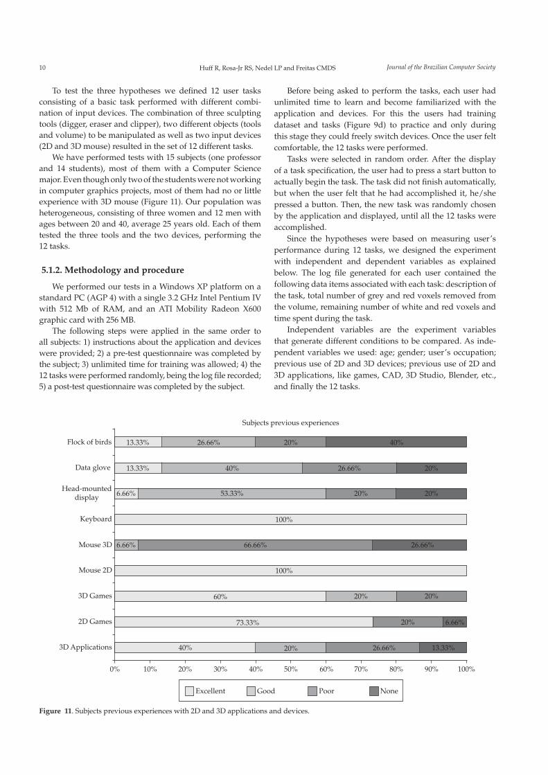
We have performed tests with 15 subjects (one professor
and 14 students), most of them with a Computer Science
major. Even though only two of the students were not working
in computer graphics projects, most of them had no or little
experience with 3D mouse (Figure 11). Our population was
heterogeneous, consisting of three women and 12 men with
ages between 20 and 40, average 25 years old. Each of them
tested the three tools and the two devices, performing the
12 tasks.
5.1.2. Methodology and procedure
We performed our tests in a Windows XP platform on a
standard PC (AGP 4) with a single 3.2 GHz Intel Pentium IV
with 512 Mb of RAM, and an ATI Mobility Radeon X600
graphic card with 256 MB.
The following steps were applied in the same order to
all subjects: 1) instructions about the application and devices
were provided; 2) a pre-test questionnaire was completed by
the subject; 3) unlimited time for training was allowed; 4) the
12 tasks were performed randomly, being the log file recorded;
5) a post-test questionnaire was completed by the subject.
Before being asked to perform the tasks, each user had
unlimited time to learn and become familiarized with the
application and devices. For this the users had training
dataset and tasks (Figure 9d) to practice and only during
this stage they could freely switch devices. Once the user felt
comfortable, the 12 tasks were performed.
Tasks were selected in random order. After the display
of a task specification, the user had to press a start button to
actually begin the task. The task did not finish automatically,
but when the user felt that he had accomplished it, he/she
pressed a button. Then, the new task was randomly chosen
by the application and displayed, until all the 12 tasks were
accomplished.
Since the hypotheses were based on measuring user’s
performance during 12 tasks, we designed the experiment
with independent and dependent variables as explained
below. The log file generated for each user contained the
following data items associated with each task: description of
the task, total number of grey and red voxels removed from
the volume, remaining number of white and red voxels and
time spent during the task.
Independent variables are the experiment variables
that generate different conditions to be compared. As inde-
pendent variables we used: age; gender; user’s occupation;
previous use of 2D and 3D devices; previous use of 2D and
3D applications, like games, CAD, 3D Studio, Blender, etc.,
and finally the 12 tasks.
Flock of birds
Data glove
Head-mounteddisplay
Keyboard
Mouse 3D
Mouse 2D
3D Games
2D Games
3D Applications
0% 10% 20% 30% 40% 50% 60% 70% 80% 90% 100%
13.33%
13.33%
6.66%
6.66%
6.66% 66.66%
53.33%
13.33%
100%
100%
40%
60%
73.33%
26.66%
26.66%
26.66%
26.66%
20%
20%
20%
20%
20%
20%
20%
20%
40%
40%
Excellent Good Poor None
Subjects previous experiences
Figure 11. Subjects previous experiences with 2D and 3D applications and devices.

11Volume sculpting based on geometric tools2009; 15(2)
Dependent variables are measures taken during the
execution of tasks. They can be objective, as the time spent
to accomplish a task, or subjective, like the level of satisfac-
tion, collected from post-test questionnaires answered by the
subjects. The dependent variables used in our experiment
were: task completion time; error rate and device preference.
The completion time was measured from the beginning
of each task until the user finished it by pressing a button.
The error rate (Equation 2) took into account the error after
the sculpting task is completed and time spent to perform the
task, as given by Equation 2:
error_rate = * T (2)
where T is completion time and is given by Equation 3:
=#
e eR W
voxels (3)
with Re being the number of remaining red voxels and W
e the
number of deleted grey voxels.
Finally, ease of use and device preference were verified
through the analysis of questionnaires.
5.1.3. Results and discussion
For the statistical analysis of collected data, several varia-
bles were considered. These variables were obtained through
the pre- and post-test questionnaires and the log files. The
pre-test form answered by the subjects provided us with
their previous experience with 2D and 3D applications and
devices (Figure 11). This table shows that the users had excel-
lent previous experience using the 2D mouse and keyboard,
but only a few of them had experience with the 3D mouse.
The correlation between the data from the pre-test ques-
tionnaire and the log files (independent and dependent
variables) was calculated.
It was possible to verify that performance with the digger
and clipper tasks was correlated to the previous experiences
of the subjects with 3D devices, especially when the user
had to use the 2D mouse to manipulate the tools and the
3D mouse to control the volume (r > 0.514, p < 0.05). Other
variables, like age and gender, did not show having influence
on performance.
We used ANOVA (Analysis of Variance) to verify the
significance of the time and error results obtained from the
log files.
To evaluate the first hypothesis (The manipulation of the
tools is faster using a conventional mouse) the time spent by the
users to complete each task was analyzed. ANOVA results
showed that the difference of the time spent in each task was
significant only for the digger (F = 5.308, p < 0.02) and eraser
(F = 4.663, p < 0.04) tools. When setting the 2D mouse for
controlling volume manipulation, the mean time using the
3D mouse for guiding the tool is higher than the time spent
using the 2D mouse for that, both for the digger and the eraser
(Figure 12).
In order to verify the second hypothesis (The error rate
decreases when users adopt the 3D device to manipulate the tool),
the error rate was calculated multiplying user’s error by the
time spent in each task, as stated in Equation 2. The user’s
error was the number of remaining red voxels and deleted
grey voxels (recalling that the task was to remove only the
red voxels). The difference of performance was not signifi-
cant according to ANOVA. Therefore the second hypothesis
was not confirmed.
The analysis of the post-test questionnaire confirmed
the third hypothesis (The users will prefer two-handed input,
using both device simultaneously to manipulate volume and
tools). Figure 13a shows that the great majority of the users
preferred the 2D mouse to manipulate the tools and the 3D
mouse to control the volume separately. Figure 13b shows
that the users also preferred this combination of devices for
two-handed input.
73.8000
140.8000
103.5384
63.4615
2D Mouse 3D Mouse
160
140
120
100
80
60
40
20
0
Tim
e (s
eco
nd
s)
Digger Eraser
Figure 12. Digger and Eraser mean times (in seconds) when control-
ling the volume with the 2D mouse.
Figure 13. a) Preferred device to control the volume or tools; and
b) preferred combination of devices.
26.67%
26.67%
46.67%
73.33%
73.33%
53.33%
33.33%66.67%
0% 50% 100%
Volume
Eraser
Digger
Clipper
2D Mouse 3D Mouse
a
26.66%
66.66%6.66%
Volume: 2D MouseTools: 2D Mouse
Volume: 3D MouseTools: 2D Mouse
Volume: 3D MouseTools: 3D Mouse
b

Journal of the Brazilian Computer Society12 Huff R, Rosa-Jr RS, Nedel LP and Freitas CMDS
5.2. Are 3D tools better than 2D ones?
Regarding the volume sculpting tools, our main goal
was to make them intuitive and easy to manipulate. To
compare user’s performance using 2D and 3D tools we chose
the conventional mouse to control both the volume to be
sculpted and the actual sculpting tools. This was supported
by the results from the first set of experiments. Rotation of the
volume was implemented by dragging the mouse with the
right button pressed, while the left button is used to apply
the tools to the volume.
The manipulation of 2D tools with a conventional mouse
is trivial, since all tools have the same degrees of freedom
(DOFs), and follows the convention shown in Figure 10.
Depth perception was enhanced through visual feedback
provided by lighting, fake shadows, guide lines, grid and
rulers.
The interface of our application also provides some
other features to help with the use of sculpting tools. Axial,
coronal and saggital sections of the volume can be shown to
allow observation of inner structures of the dataset during
the use of digger tools (see Figure 10). The 3D Eraser tool
can be rotated and additional translation options are also
available.
The evaluation was based on three hypotheses, all of them
regarding the use of the two different sets of sculpting tools,
i.e., using the virtual pointer metaphor (2D) or the virtual
hand (3D):
using the 3D ones.
volume sculpting tools.
The first hypothesis was conceived upon the fact that
regular users are familiar with 2D interactive tools, and the
training period in 3D tools is not enough to provide them
the same skills to manipulate 3D tools as they would have
with 2D ones. The second hypothesis, on the other hand,
was based on the consideration that 3D tasks are better
performed using a 3D interaction metaphor, because some
problems of mapping from 3D to 2D (as the projection, for
example) would be avoided. Finally, the third hypothesis
relied on the cognitive benefits from the reduction of the
workload of mentally decomposing 3D tasks into unnatural
2D tasks.
5.2.1. Scenario and subjects
As before, the experiment consisted on the elimination of
red voxels from red-and-grey volumes. In order to facilitate
the visualization of cuts and holes, illumination and a marble
procedural texture were applied onto the volumes.
The testbed application used 5 phantom datasets as input,
each one composed by a stack of images with red and grey
pixels: one for training the users before they start the evalua-
tion process (Figure 14a); three for the evaluations of the
tools (digger, eraser and clipper), independent of the interac-
tion technique applied (Figures 14b-d); and a fifth volume to
evaluate the use of the three tools concurrently (Figure 14e).
All datasets used were opaque. Transparency was used in
Figure 14 only to illustrate inner structures.
Tests were performed by 16 Computer Science students,
most of them knowledgeable in Computer Graphics. In spite
of that, the pre-test questionnaires analysis showed that most
of them had little experience with 3D environments. The
subjects were between 20 and 29 years old, average of 23.5
and there were only three women in the group. Each of the
subjects tested the six sculpting tools in eight tasks.
5.2.2. Methodology and procedure
We performed the experiments on a HP Pavillion zd8000
notebook with a single 3.20 GHz Intel Pentium IV CPU,
512 MB of RAM, ATI Radeon X600 PCI Express x16 graphics
card with 256MB, running WindowsXP.
The following steps were performed in the same order by
each subject: 1) instructions about the application and devices
were provided; 2) a pre-test questionnaire was completed;
3) unlimited time for training was allowed; 4) the 8 tasks
were performed in a defined order; and 5) a post-test ques-
tionnaire was completed.
Tasks were presented to users in a certain order; after the
display of a task specification, the user had to press a start
button to actually begin the task. The task did not finish
automatically, and when the user felt that he/she had accom-
plished it, he/she pressed a button. Then, the new task was
displayed by the application, until all the 8 tasks were accom-
plished.
Users were separated into two groups with the same size
to avoid the order factor: one group tested the 2D set of tools
first than the 3D, while the other did the opposite. Each set
of tools was evaluated in the same order: the digger tool was
followed by the eraser and clipper, and the task to evaluate all
Figure 14. Datasets for experiment 2: a) a cube and a cylinder, for training; b) a mushroom, for the digger evaluation; c) a teapot, for the eraser
evaluation; d) a cube, for the clipper evaluation; and e) a bitten apple, for the evaluation of the three tools at the same time.
a b c d e

13Volume sculpting based on geometric tools2009; 15(2)
the tools together was the last one. This order was selected
based on results obtained from the previous experiment.
For each user, a log file was generated with the following
data items associated with each task: task id; total number of
grey and red voxels of the volume; remaining number of grey
and red voxels; time spent in the task; and history of actions
performed.
As independent variables we used: age; gender; user’s
occupation; previous use of 2D and 3D devices; previous
use of 2D and 3D applications such as image editors, games,
CAD, 3D Studio Max, Blender, etc.; and the eighth tasks.
The dependent variables considered were: task comple-
tion time; error rate; and device preference. The completion
time was measured from the beginning of each task until the
user finished it by clicking on a button in the system inter-
face. The error rate is calculated as in the first experiments
(Equation 2).
Ease of use and device preference were verified through
the analysis of questionnaires.
5.2.3. Results and discussion
The pre-test form answered by the subjects provided us
with their previous experience with 2D and 3D applications.
The correlation between the data from the pre-test question-
naires and the data saved in the log files was calculated.
There was no correlation between previous experiences that
the subjects had with the performance obtained during this
second set of tests. Other variables like age and gender did
not show any correlation too.
As before, we used ANOVA to verify the significance of
time and error results obtained from log files. To evaluate the
first hypothesis (Using the 2D volume sculpting tools is faster
than using the 3D ones) the time spent by the users to complete
each task was analyzed.
ANOVA test results showed that the difference in the
time spent in each task was significant only for tasks where
we allowed the use of all the tools together (F = 9.433,
p < 0.00494). In this case, the first hypothesis was confirmed,
because the mean time of sculpting the volume using the 3D
tools was much higher than the mean time spent with the 2D
tools (Figure 15).
In order to verify the second hypothesis (The error rate
decreases when using the 3D volume sculpting tools), the error
rate was calculated multiplying the user’s error by the time
spent in each task, as stated in Equation 2. The difference of
performance was significant according to ANOVA when the
users tested the eraser (F = 42.222, p < 6.90207E – 07) and the
clipper tools (F = 4.264, p = 0.0490). In these cases, the second
hypothesis was confirmed because the error rate when
using the 2D tools was higher than when using the 3D ones
(Figure 16).
The analysis of post-test questionnaires confirmed the
third hypothesis (Subjects prefer the 3D volume sculpting
tools). Figure 17 shows that most of the users preferred 3D
interaction techniques for sculpting volumes. The only case
where this hypothesis was not confirmed was for eraser tools
Figure 15. Mean time for tasks combining the use of eraser, digger
and clipper concurrently.
566.5714
566.5714
2D Tools 3D Tools0
100
200
300
400
500
600
700
800
900
1000
Tim
e (s
eco
nd
s)
Mean time using three tools in the same task
Figure 16. Mean error rate for eraser and clipper tools.
6.0578
1.4934
7.3239
14.5711
2D 3D
Err
or
× T
ime
Eraser and Clipper mean error rate16
14
12
10
8
6
4
2
0
Eraser Clipper
Figure 17. Preference of the users after the evaluation of 2D and 3D
volume sculpting tools.
37.50%
56.25%
81.25%
31.25%
18.75%
38.75%
43.75%
62.50%In general
Eraser
Digger
Clipper
0% 50% 100%
2D Interaction 3D Interaction
evaluation. Even though the users preferred the 2D Eraser,
the performance analysis (Figure 16) shows that the 2D Eraser
was much worse than the 3D Eraser. This is probably due to
the illusion that the 2D Eraser removes the voxels as if it was
a cylinder perpendicular to the view plane, instead of a cone.
The illusion is caused by the perspective projection intrinsic
to the Aperture Selection technique.
Journal of the Brazilian Computer Society14 Huff R, Rosa-Jr RS, Nedel LP and Freitas CMDS
6. Filling Tools
Volumetric datasets can also be used for modelling
missing structures, as exemplified in Figure 2. Such structures
can be sculpted by inserting material in selected voxels, and
can be used to build models of prosthesis based on isosur-
faces extracted from the sculpted volumes.
Since our volume sculpting tools were developed based
on selection and marking of voxels inside volumetric
datasets, it was a straightforward idea to devise tools that
instead of cutting out volume parts would add material
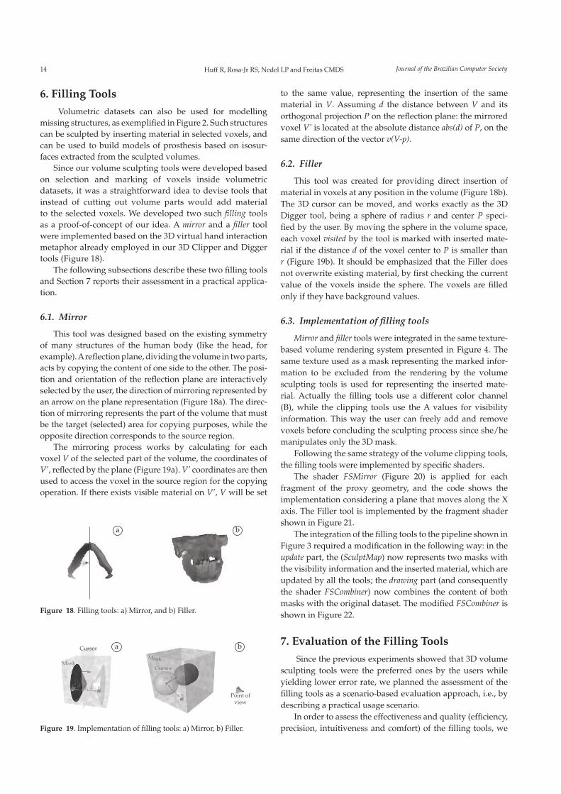
to the selected voxels. We developed two such filling tools
as a proof-of-concept of our idea. A mirror and a filler tool
were implemented based on the 3D virtual hand interaction
metaphor already employed in our 3D Clipper and Digger
tools (Figure 18).
The following subsections describe these two filling tools
and Section 7 reports their assessment in a practical applica-
tion.
6.1. Mirror
This tool was designed based on the existing symmetry
of many structures of the human body (like the head, for
example). A reflection plane, dividing the volume in two parts,
acts by copying the content of one side to the other. The posi-
tion and orientation of the reflection plane are interactively
selected by the user, the direction of mirroring represented by
an arrow on the plane representation (Figure 18a). The direc-
tion of mirroring represents the part of the volume that must
be the target (selected) area for copying purposes, while the
opposite direction corresponds to the source region.
The mirroring process works by calculating for each
voxel V of the selected part of the volume, the coordinates of
V’, reflected by the plane (Figure 19a). V’ coordinates are then
used to access the voxel in the source region for the copying
operation. If there exists visible material on V’, V will be set
to the same value, representing the insertion of the same
material in V. Assuming d the distance between V and its
orthogonal projection P on the reflection plane: the mirrored
voxel V’ is located at the absolute distance abs(d) of P, on the
same direction of the vector v(V-p).
6.2. Filler
This tool was created for providing direct insertion of
material in voxels at any position in the volume (Figure 18b).
The 3D cursor can be moved, and works exactly as the 3D
Digger tool, being a sphere of radius r and center P speci-
fied by the user. By moving the sphere in the volume space,
each voxel visited by the tool is marked with inserted mate-
rial if the distance d of the voxel center to P is smaller than
r (Figure 19b). It should be emphasized that the Filler does
not overwrite existing material, by first checking the current
value of the voxels inside the sphere. The voxels are filled
only if they have background values.
6.3. Implementation of filling tools
Mirror and filler tools were integrated in the same texture-
based volume rendering system presented in Figure 4. The
same texture used as a mask representing the marked infor-
mation to be excluded from the rendering by the volume
sculpting tools is used for representing the inserted mate-
rial. Actually the filling tools use a different color channel
(B), while the clipping tools use the A values for visibility
information. This way the user can freely add and remove
voxels before concluding the sculpting process since she/he
manipulates only the 3D mask.
Following the same strategy of the volume clipping tools,
the filling tools were implemented by specific shaders.
The shader FSMirror (Figure 20) is applied for each
fragment of the proxy geometry, and the code shows the
implementation considering a plane that moves along the X
axis. The Filler tool is implemented by the fragment shader
shown in Figure 21.
The integration of the filling tools to the pipeline shown in
Figure 3 required a modification in the following way: in the
update part, the (SculptMap) now represents two masks with
the visibility information and the inserted material, which are
updated by all the tools; the drawing part (and consequently
the shader FSCombiner) now combines the content of both
masks with the original dataset. The modified FSCombiner is
shown in Figure 22.
7. Evaluation of the Filling Tools
Since the previous experiments showed that 3D volume
sculpting tools were the preferred ones by the users while
yielding lower error rate, we planned the assessment of the
filling tools as a scenario-based evaluation approach, i.e., by
describing a practical usage scenario.
In order to assess the effectiveness and quality (efficiency,
precision, intuitiveness and comfort) of the filling tools, we
Figure 18. Filling tools: a) Mirror, and b) Filler.
a b
Figure 19. Implementation of filling tools: a) Mirror, b) Filler.
MaskMaskMaskMaskMaskMaskMaskMask
MaskMask
Cursor
CursCursoror
v’v’vv
v
d’d’ ddddddddddd
ppppppp
ppp r
Point of
view
a b
15Volume sculpting based on geometric tools2009; 15(2)
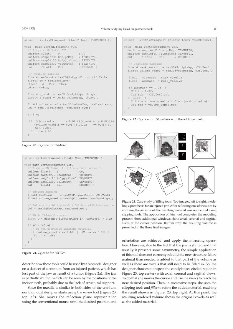
orientation are achieved, and apply the mirroring opera-
tion. However, due to the fact that the jaw is shifted and that
usually it presents some asymmetry, the simple application
of this tool does not correctly rebuild the new structure. More
material than needed is added to that part of the volume as
well as there are voxels that still need to be filled in. So, the
designer chooses to inspect the condyle (see circled region in
Figure 23, top center) with axial, coronal and sagittal views.
To do that she moves the cursor and use the views to reach the
new desired position. Then, in successive steps, she uses the
clipping tools and filler to refine the added material, reaching
the result shown in Figure 23, top right. At this point, the
resulting rendered volume shows the original voxels as well
as the added material.
Figure 22. Cg code for FSCombiner with the additive mask.
struct vertex2fragment {float2 Tex0: TEXCOORD0;};
void main(vertex2fragment v2f,
// P.xyz = 3D Point ‘P’
uniform float4 P : C0,
uniform sampler3D SculptMap : TEXUNIT0,
uniform sampler2D PolygonCoord: TEXUNIT1,
uniform sampler3D VolumeTex : TEXUNIT2,
out float4 Col : COLOR0) {
// Texture mapping
float4 texCoord = tex2D(PolygonCoord, v2f.Tex0);
float3 t0 = texCoord.xyz;
float d = P.x - t0.x;
t0.x = d+P.x;
float4 r_mask = tex3D(SculptMap, t0.xyz);
float4 r_texel = tex3D(VolumeTex, t0.xyz);
float4 volume_voxel = tex3D(VolumeTex, texCoord.xyz);
Col = tex3D(SculptMap, texCoord.xyz);
d*=P.w;
if (((r_texel.r != 0.0f)&&(r_mask.a != 0.0f))&&
((volume_voxel.r == 0.0f)||(Col.a == 0.0f))&&
(d > 0.0f)){
Col.b = 1.0f;
}
}
Figure 20. Cg code for FSMirror.
struct vertex2fragment {float2 Tex0: TEXCOORD0;}; void main(vertex2fragment v2f, uniform sampler3D SculptMap: TEXUNIT0, uniform sampler3D VolumeTex: TEXUNIT1, out float4 Col : COLOR0) { // Textures mapping float4 mask_voxel = tex3D(SculptMap, v2f.Tex0); float4 volume_voxel = tex3D(VolumeTex, v2f.Tex0); float viewmask = mask_voxel.a; float addmask = mask_voxel.b; if (addmask == 1.0f) { Col.a = 1.0f; Col.rgb = v2f.Tex0.rgb; } else { Col.a = volume_voxel.a * floor(mask_voxel.a); Col.rgb = volume_voxel.rgb; } }
Figure 21. Cg code for FSFiller.
struct vertex2fragment {float2 Tex0: TEXCOORD0;}; void main(vertex2fragment v2f, // P.xyz = 3D Point ‘P’ | P.a = tool radius ‘r’ uniform float4 P : C0, uniform sampler3D SculptMap : TEXUNIT0, uniform sampler2D PolygonCoord: TEXUNIT1, uniform sampler3D VolumeTex : TEXUNIT2, out float4 Col : COLOR0) { // Texture mapping float4 texCoord = tex2D(PolygonCoord, v2f.Tex0); float4 volume_voxel = tex3D(VolumeTex, texCoord.xyz); // Col.a = visibility mask | Col.b = addition texture
Col = tex3D(SculptMap, texCoord.xyz); // 3D Euclidean distance float D = distance(float4(P.xyz,1), texCoord) / P.a; if (D < Col.a) { // Do not overwrite existing material if (volume_voxel.r == 0.0f) || (Col.a == 0.0f) { Col.b = 1.0f; } } }
describe how these tools could be used by a biomodel designer
on a dataset of a cranium from an injured patient, which has
lost part of the jaw as result of a tumor (Figure 2a). The jaw
is partially shifted, which can be seen by the positions of the
incisor teeth, probably due to the lack of structural support.
Since the maxilla is similar in both sides of the cranium,
our biomodel designer starts using the mirror tool (Figure 23,
top left). She moves the reflection plane representation
using the conventional mouse until the desired position and
Figure 23. Case study of filling tools. Top images, left to right: mode-
ling a prosthesis for an injured jaw. After reflecting one of the sides by
applying the mirror tool, the resulting material was segmented using
clipping tools. The application of filler tool completes the modeling
process: three additional windows show axial, coronal and sagittal
slices at the cursor position. Bottom row: the resulting volume is
presented in the three final images.

Journal of the Brazilian Computer Society16 Huff R, Rosa-Jr RS, Nedel LP and Freitas CMDS
As a final step, the designer can submit the combined
volume to a mesh extraction method and obtain a geometric
model of the added structure. This model could then be used
with rapid prototyping tools to build physical models to
serve as implants for our patient.
8. Final Remarks
We presented a set of volume sculpting tools using both
2D and 3D interaction techniques to allow exposing inner
parts of volumes. We also investigated filling tools to allow
the user to build structures that fit in the volume data, filling
gaps for building prosthesis, for example. The proposed
tools are based on the multi-texturing facilities provided by
modern GPUs and implemented in special fragment shaders
that discard fragments based on visibility information. This
way we achieved real-time performance in volume and tools
manipulation.
A first set of experiments with users allowed us to evaluate
the use of different devices to interact with the application for
manipulating the sculpting tools and controlling the volume
position and orientation. Analysis of results showed that,
in the few cases where the difference of performance was
significant, using the 2D mouse to control the tools allowed
a better time performance. Moreover, although the results
were not significant under ANOVA, the error rate was lower
when using the 3D mouse for controlling the tools. Analysis
of the questionnaires showed that the users prefer to use
both hands and both devices (2D mouse for moving the tool
and 3D mouse for manipulating the volume) to perform the
sculpting tasks. As a conclusion, collected data shows that
better results are obtained when the mapping between the
interaction in the real and virtual worlds is direct.
A second set of experiments was carried out to find the
best set of tools (2D or 3D) from the user’s point of view.
Analyses of results showed that when all tools that are based
on the same interaction metaphor are used together, the mean
time of those that use 3D interaction is higher. This would
be interpreted as a disadvantage of our 3D volume sculpting
tools if we had taken only time as a performance measure.
Significant results favoring the 3D tools were obtained when
analyzing the error rate. Users had fewer errors when using
techniques based on the virtual hand metaphor. The prefer-
ence of the users, obtained from questionnaires, was also for
the use of the 3D volume sculpting tools.
Based on results favoring 3D interaction tools we devel-
oped filling tools so the user can build structures that can be
further visualized or extracted as meshes. These tools have
direct application to the design of biomedical models to serve
as prosthesis and implants. Two case studies were conducted
as an assessment of such tools, one was reported here. Next
steps of our work are concentrated on validating filling tools
by building a physical prototype of the added structure in
order to compare it with the prosthesis built by designers
following conventional procedures.
Acknowledgements
We gratefully acknowledge the experimental users as well
as all colleagues from the Computer Graphics Lab at UFRGS
for suggestions and helpful comments. We also acknowledge
the financial support from CNPq, and the Design and Material
Selection Laboratory (LdSM) from UFRGS, mainly Liciane
Bertol, for sharing with us her experience in biomodel design
and providing us the data we used in the case studies
References
1. Bowman DA and Hodges LF. An Evaluation of Techniques for
Grabbing and Manipulating Remote Objects in Immersive Virtual
Environments. Providence, RI, USA: ACM; 1997. p. 35-38.
2. Bowman DA, Johnson D and Hodges LF. Testbed Evaluation
of Virtual Environment Interaction Techniques. Presence:
Teleoperators and Virtual Environments 2001;10(1):75-95.
3. Bruckner S and Gröller E. Enhancing Depth-Perception with
Flexible Volumetric Halos. IEEE Transactions on Visualization
and Computer Graphics 2007;13(6):1344-1351.
4. Bruckner S and Gröller ME. VolumeShop: An Interactive
System for Direct Volume Illustration. Proceedings of the IEEE
Conference on Visualization; 2005. p. 671-678.
5. Buxton W and Meyers BA. A Study in Two-Handed Input.
Proceedings of the SIGCHI Conference on Human Factors in
Computing Systems; 1986; Boston, MA, USA. p. 321-326.
6. Chen HJ, Samavati FF and Sousa MC. GPU-based point
radiation for interactive volume sculpting and segmentation.
The Visual Computer 2008;24(7):689-698.
7. Correa CD and Silver D. Programmable shaders for
deformation rendering. GH ‘07: Proceedings of the 2007 ACM
SIGGRAPH/EUROGRAPHICS conference on Graphics hardware;
2007; Aire-la-Ville, Switzerland. p. 89-96.
8. Pinto FM and Dal Sasso Freitas CM. Design of Multi-
dimensional Transfer Functions Using Dimensional
Reduction. EuroVis07: Joint Eurographics - IEEE VGTC
Symposium on Visualization; 2007; Sweden. p. 131-138.
9. Diepstraten J, Weiskopf D and Ertl T. Transparency in
Interactive Technical Illustrations. Computer Graphics Forum
2002;21(3):125-148.
10. Ebert D and Rheingans P. Volume Illustration: Non-Pho-
torealistic Rendering of Volume Models. Proceedings of the
IEEE Conference on Visualization; 2000. p. 195-202.
11. Engel K, Kraus M and Ertl T. High-Quality Pre-Integrated
Volume Rendering Using Hardware-Accelerated Pixel
Shading. Proceedings of the ACM SIGGRAPH/EUROGRAPHICS
Workshop on Graphics Hardware, HWWS; 2001; Los Angeles,
CA, USA. p. 9-16
12. Forsberg A, Herndon K and Zeleznik R. Aperture Based
Selection for Immersive Virtual Environments. Proceedings of
the ACM Symposium on User Interface Software and Technology,
UIST; 1996; Seattle, WA, USA. p. 95-96.
13. Galyean TA and Hughes JF. Sculpting: an interactive
volumetric modeling technique. Proceedings of the Annual
Conference on Computer Graphics and Interactive Techniques,
SIGGRAPH, 18; 1991; Las Vegas, NV, USA. p. 267-274.

17Volume sculpting based on geometric tools2009; 15(2)
14. Van Gelder A and Kim K. Direct Volume Rendering with
Shading via Three-Dimensional Textures. Proceedings of the
Symposium on Volume Visualization, VVS; 1996; San Francisco,
CA, USA. p. 23-30.
15. Hinckley K, Pausch R, Goble JC and Kassell NF. A Survey of
Design Issues in Spatial Input. Proceedings of the Annual ACM
SIGGRAPH Symposium on User Interface Software and Technology,
UIST, 7; 1994; Marina del Rey, CA, USA. p. 213-222.
16. Huff R, Dietrich CA, Nedel LP, Dal Sasso Freitas CM,
Dihl Comba JL and Olabarriaga SD. Erasing, Digging and
Clipping in Volumetric Datasets with One or Two Hands.
Proceedings of the ACM International Conference on Virtual
Reality Continuum and Its Applications, VRCIA; 2006; Hong
Kong, 2006. p. 271-278.
17. Islam S, Silver D and Chen M. Volume Splitting and Its
Applications. IEEE Transactions on Visualization and Computer
Graphics 2007;13(2):193-203.
18. Kindlmann G, Whitaker R, Tasdizen T and Möller T.
Curvature-Based Transfer Functions for Direct Volume
Rendering: Methods and Applications. Proceedings of the
IEEE Conference on Visualization, VIS; 2003. p. 513-520.
19. Kniss J, Kindlmann G and Hansen C. Interactive Volume
Rendering Using Multi-Dimensional Transfer Functions
and Direct Manipulation Widgets. Proceedings of the IEEE
Conference on Visualization, VIS ; 2001; San Diego, CA, USA.
Washington: IEEE Computer Society. p. 255-262
20. Leganchuk A, Zhai S and Buxton W. Manual and Cognitive
Benefits of Two-Handed Input: An Experimental Study.
ACM Transactions on Computer-Human Interaction 1998;
5(4):326-359.
21. Liang J and Green M. Geometric modeling using six degrees
of freedom input devices. Proceedings of the International
Conference on Computer Aided Design and Computer Graphics,
CAD/CG, 3; 1993; Beijing, China. p. 217-222.
22. Lorensen WE. Geometric clipping using boolean textures.
Proceedings of the IEEE Conference on Visualization; 1993; San
Jose, CA, USA. p. 268-274.
23. McGuffin M, Tancau L and Balakrishnan R. Using
deformations for browsing volumetric data. Proceedings of the
IEEE Conference on Visualization, VIS; 2003. p. 401-408.
24. Mine MR. Virtual Environment Interaction Techniques. Chapel
Hill, NC, USA: University of North Carolina at Chapel Hill,
Computer Science Department; 1995. Technical report
25. Mine MR, Brooks Jr. FP and Sequin CH. Moving objects in
space: exploiting proprioception in virtual-environment
interaction. Proceedings of the Annual Conference on Computer
Graphics and Interactive Techniques, SIGGRAPH, 24; 1997; Los
Angeles, CA, USA. p. 19-26
26. Nedel LP, Dal Sasso Freitas CM, Jacob LJ and Pimenta MS.
Testing the Use of Egocentric Interactive Techniques in
Immersive Virtual Environments. Proceedings of IFIP TC13
International Conference on Human-Computer Interaction,
INTERACT, 9; 2003; Zürich, Switzerland. Amsterdam: IOS
Press. p. 471-478.
27. Parviainen J, Sainio N and Raisamo R. Perceiving Tools in 3D
Sculpting. Proceedings of the Asia-Pacific Computer and Human
Interaction, APCHI, 6; 2004; Rotorua, New Zealand. Berlin:
Springer-Verlag. p. 328-337.
28. Pfister H, Hardenbergh J, Knittel J, Lauer H and Seiler L.
The VolumePro Real-Time Ray-Casting System. Proceedings
of the Annual Conference on Computer Graphics and Interactive
Techniques, SIGGRAPH, 26; 1999; Los Angeles, CA, USA.
p. 251-260.
29. Pfister H, Lorensen WE, Schroeder WJ, Bajaj CL and
Kindlmann GL. The transfer function bake-off (panel session).
Proceedings of the IEEE Conference on Visualization, VIS; 2000.
p. 523-526.
30. Pflesser B, Petersik A, Tiede U, Höhne KH and Leuwer R.
Volume cutting for virtual petrous bone surgery. Computer
Aided Surgery 2002;7(2):74-83.
31. Pierce JS, Forsberg AS, Conway MJ, Hong S, Zeleznik RC and
Mine MR. Image Plane Interaction Techniques in 3D Immersive
Environments. Providence, RI, USA: ACM; 1997. P. 39-43.
32. Poupyrev I, Billinghurst M, Weghorst S and Ichikawa T.
The Go-Go Interaction Technique: Non-Linear Mapping
for Direct Manipulation in VR. Proceedings of the Annual
ACM SIGGRAPH Symposium on User Interface Software and
Technology, UIST, 9; 1996; Seattle, WA, United States. p. 79-80
33. Poupyrev I, Weghorst S, Billinghurst M and Ichikawa T.
Egocentric Object Manipulation in Virtual Environments:
Evaluation of Interaction Techniques. Computer Graphics
Forum 1998; 17(3):41-52.
34. Rezk-Salama C, Engel K, Bauer M, Greiner G and
Ertl T. Interactive Volume Rendering on Standard PC
Graphics Hardware Using Multi-Textures and Multi-
Stage Rasterization. Proceedings of the ACM SIGGRAPH/
EUROGRAPHICS Workshop on Graphics Hardware, HWWS;
2000; Interlaken, Switzerland. p. 109-118.
35. Sachs E, Roberts A and Stoops D. 3-Draw: A Tool for Designing
3D Shapes. IEEE Computer Graphics and Applications 1991;
11(6):18-26.
36. Song D and Norman M. Nonlinear Interactive Motion
Control Techniques for Virtual Space Navigation. Proceedings
of IEEE Virtual Reality Annual International Symposium, VR;
1993; Seattle, WA, USA. p. 111-117.
37. Wang SW and Kaufman AE. Volume Sculpting. Monterey, CA,
USA: ACM; 1995. p. 151-156.
38. Weiskopf D, Engel K and Ertl T. Interactive Clipping
Techniques for Texture-Based Volume Visualization and
Volume Shading. IEEE Transactions on Visualization and
Computer Graphics 2003; 9(3):298-312.
39. Weiskopf D, Engel K and Ertl T. Volume Clipping via
Per-Fragment Operations in Texture-Based Volume
Visualization. Proceedings of the IEEE Conference on
Visualization, VIS; 2002; Boston, MA. p. 93-100.
40. Westermann R and Ertl T. Efficiently Using Graphics Hardware
in Volume Rendering Applications. Proceedings of the Annual
Conference on Computer Graphics and Interactive Techniques,
SIGGRAPH, 25; 1998; Orlando, FL, USA. p. 169-177.
41. Wu Y and Qu H. Interactive Transfer Function Design Based
on Editing Direct Volume Rendered Images. IEEE Transactions
on Visualization and Computer Graphics 2007; 13(5):1027-1046.

Journal of the Brazilian Computer Society18 Huff R, Rosa-Jr RS, Nedel LP and Freitas CMDS
Color Plate
Figure 23. Case study of filling tools. Top images, left to right: modeling a prosthesis for an injured jaw. After reflecting one of the sides by
applying the mirror tool, the resulting material was segmented using clipping tools. The application of filler tool completes the modeling
process: three additional windows show axial, coronal and sagittal slices at the cursor position. Bottom row: the resulting volume is presented
in the three final images.
Figure 1. Volumetric Sculpting Tools: a) 3D Eraser, b) 3D Digger, c) 3D Clipper, d) 2D Eraser, e) 2D Digger and f) 2D Clipper.
a b c
d e f
Top Related