


Languages
Pages
Legal

lable at ScienceDirect
Journal of Structural Geology 32 (2010) 1279–1290
Contents lists avai
Journal of Structural Geology
journal homepage: www.elsevier .com/locate/ jsg
Evolution of anastomosing crack–seal vein networks in limestones: Insight froman exhumed high-pressure cell, Jabal Shams, Oman Mountains
Marc Holland*,1, Janos L. UraiStructural Geology Tectonics Geomechanics, RWTH Aachen University, Lochnerstrasse 4-20, D-52066 Aachen, Germany
a r t i c l e i n f o
Article history:Received 12 January 2008Received in revised form12 August 2008Accepted 9 April 2009Available online 5 May 2009
Keywords:Zebra carbonateCrack–sealAnastomosingVeins
* Corresponding author. Fax: þ49 2418092358.E-mail address: [email protected] (M. HollandURL: http://www.ged.rwth-aachen.de
1 Present address: GeoMechanics InternationalD-55116 Mainz, Germany.
0191-8141/$ – see front matter � 2009 Elsevier Ltd. Adoi:10.1016/j.jsg.2009.04.011
a b s t r a c t
We studied a special type of zebra carbonate in limestones of an overpressure cell exhumed from at 5 kmdepth, in outcrops on Jabal Shams, Oman Mountains. The rocks show anastomosing patterns of regularlyspaced calcite veins in dark gray, fine-grained carbonate; microscopic observations reveal these as densebundles of much finer veinlets, typically 10–50 mm thick. The vein bundles are up to 5 mm thick, theycontain multiple sub-parallel arrays of host rock fragments embedded in the coarse-grained vein calcite.We interpret these structures as the result of numerous mechanically effective crack and reseal eventstogether with strong growth competition or crystallization from sparse nucleation sites. Cementationproduced mechanically strong veins so that new fractures were localized along the vein/rock interface orwithin the matrix itself. We present simple conceptional models relating the mechanical strength of thevein and the morphology of the resulting vein network.
� 2009 Elsevier Ltd. All rights reserved.
1. Introduction
In this study we discuss the formation of brightly colored, thincalcite veins in a dark carbonate matrix. Such a macroscopic textureis commonly described by the term ‘‘zebra-rock’’, which can beproduced by a number of different processes, such as primarysedimentation, metasomatosis as well as different means of frac-turing (e.g. Badoux et al., 2001; Merino et al., 2006; Nielsen et al.,1998, 2000; Swennen et al., 2003; Vandeginste et al., 2005; Weller,1989). In the context of these different possibilities, the study of themicro-structural properties not only reveals the processesresponsible for forming the texture, but also allows deriving thegenetic conditions. Accessing these parameters is important inorder to decide whether the presented zebra texture has thepotential to be used as indicative information.
Over a range of scales, the texture of our samples is made up ofan extremely dense network of anastomosing veins, which weinterpret to have formed by crack–seal processes (Andreani et al.,2004; Boullier and Robert, 1992; Gaviglio, 1986; Hilgers and Urai,2005; Lee and Wiltschko, 2000; Petit et al., 1999; Ramsay, 1980;Renard et al., 2005; Wiltschko and Morse, 2001). The exceptionalhigh density of healed fractures, and the corresponding pattern,
).
Inc., Emmerich Josef-Str. 5,
ll rights reserved.
raises questions on how this special form of zebra pattern wasformed. We attempt to explain the genetic conditions and presentsimple conceptual models that discuss the role of cementation inrestoring the rock strength.
2. Description
2.1. Geological framework
The samples of this study were collected on the southern flankof Jabal Shams in the Oman Mountains. The Oman Mountains arepart of the Alpine–Himalayan chain and show a complex multi-phase deformation (e.g. Al-Wardi, 2006; Al-Wardi and Butler, 2006;El-Shazly et al., 2001; Glennie, 2005; Hilgers et al., 2006; Hollandet al., 2009; Loosveld et al., 1996; Searle, 2007) of which details likethe strain portioning, timing and tectonic framework are stillunclear (e.g. Breton et al., 2004; Gray et al., 2005a,b; Gray andMiller, 2000; Searle, 2007; Searle et al., 2005; Warren and Miller,2007; Warren et al., 2003; Wilson, 2000). The area exposescarbonates and mudstones that belong to the ‘Autochthonous’Hajar Supergroup. The rocks of this group were deposited ina predominantly passive margin environment (Glennie, 2005;Hughes Clarke, 1988; Searle, 2007). The autochthonous group wassubject to a multiphase deformation related to the convergence ofthe Arabian with the Eurasian plate. This first led to a flexure of thelithosphere causing local uplift of the Arabian plate margin (El-Shazly et al., 2001; Filbrandt et al., 2006; Loosveld et al., 1996;Patton and O’Conner, 1988; Searle, 2007; Warbuton et al., 1990).
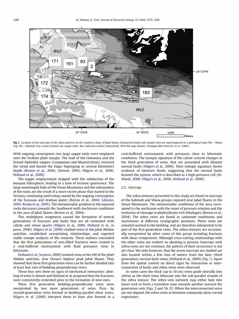
Fig. 1. Location of the outcrops of the zebra patterns on the southern slope of Jabal Shams. Interpreted faults and sample sites are superimposed on a geological map (Ws¼WasiaGrp; Kh¼ Kahmah Grp; Lined sections are nappe units; Box indicates section interpreted, WGS-84 map datum). Changed after Beurrier et al. (1986).
M. Holland, J.L. Urai / Journal of Structural Geology 32 (2010) 1279–12901280
With ongoing convergence two large nappe units were emplacedonto the Arabian plate margin. The load of the Hawasina and theSemail Ophiolite nappes (Campanian and Maastrichtian) reversedthe trend and buried the Hajar Supergoup to several kilometersdepth (Breton et al., 2004; Glennie, 2005; Hilgers et al., 2006;Holland et al., 2009).
The nappe emplacement stopped with the subduction of thebuoyant lithosphere, leading to a time of tectonic quiescence. Thelarge wavelength folds of the Oman Mountains and the exhumationof the rocks are the result of a more recent phase that started in theTertiary, continuing until today caused by the ongoing convergenceof the Eurasian and Arabian plates (Breton et al., 2004; Glennie,2005; Kusky et al., 2005). The metamorphic gradient in the exposedrocks decreases towards the Southwest with Anchizone conditionsin the area of Jabal Shams (Breton et al., 2004).
This multiphase orogenesis caused the formation of severalgenerations of fractures and faults that are all cemented withcalcite and minor quartz (Hilgers et al., 2006; Holland et al., inpress, 2009). Hilgers et al. (2006) studied veins in the Jabal Akhdaranticline, established overprinting relationships, and reportedstable isotope analyses of the cements. These authors concludedthat the first generations of vein-filled fractures were created ina rock-buffered environment with fluid pressures close tolithostatic.
Holland et al. (in press, 2009) studied veins in the SW of the JebelAkhdar anticline, near Oman’s highest peak Jabal Shams. Theyshowed that these first generation veins can be further divided intoat least four sets of bedding-perpendicular veins.
These four sets show no signs of mechanical interaction; abut-ting of veins is absent and Holland et al. proposed that the fractureswere consistently cemented prior to the formation of new ones.
These first generation bedding-perpendicular veins wereoverprinted by two more generations of veins. First- bysecond-generation veins formed in bedding-parallel shear zones.Hilgers et al. (2006) interpret these to have also formed in a
rock-buffered environment with pressures close to lithostaticconditions. The isotopic signature of the calcite cement changes inthe third generation of veins, that are associated with dilatantnormal faults (Hilgers et al., 2006). Their isotopic signature showsevidence of meteoric fluids, suggesting that the normal faultsdrained the system, which is described as a high-pressure cell (Al-Wardi, 2006; Hilgers et al., 2006; Holland et al., 2009).
2.2. Outcrops
The zebra textures presented in this study are found in outcropsof the Kahmah and Wasia groups exposed near Jabal Shams in theOman Mountains. The metamorphic conditions of the area corre-spond to the anchizone with the onset of pressure solution and theevolution of cleavage in phyllosilicate-rich lithologies (Breton et al.,2004). The zebra veins are found in carbonate mudstones andwackstones at different stratigraphic positions. These veins areoriented normal to the bedding, and are therefore interpreted to bepart of the first generation veins. The zebra textures are occasion-ally overprinted by other veins of this group including fractureswith shear components. Although cross-cutting relationships withthe other veins are evident no abutting is present. Outcrops withzebra veins are not common, the pattern of their occurrence is notyet clear. We note however, that the seven outcrops we studied arealso located within a few tens of meters from the later (thirdgeneration) normal fault zones (Holland et al., 2009) (Fig. 1). Apartfrom the spatial context no direct signs for interaction or inter-connection of faults and zebra veins were observed.
In some cases the thick (up to 10 cm) veins grade laterally intozebras as the thick veins bifurcate into the sub-parallel strands ofthe zebra texture. The zebra vein network may either fade intointact rock or form a transition zone towards another massive fistgeneration vein (Figs. 2 and 3A, D). When the interconnected veinsare not aligned, the zebra veins in between commonly show curvedtrajectories.
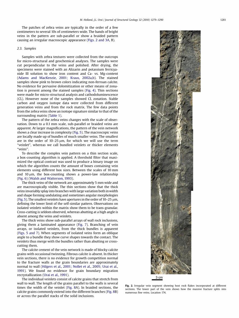
Fig. 2. Irregular vein segment showing host rock flakes incorporated at differentsections. The lower part of the vein shows how the massive fracture splits intonumerous fine veins. Location 174.
M. Holland, J.L. Urai / Journal of Structural Geology 32 (2010) 1279–1290 1281
The patches of zebra veins are typically in the order of a fewcentimeters to several 10s of centimeters wide. The bands of brightveins in the pattern are sub-parallel or show a braided patterncausing an irregular macroscopic appearance (Figs. 2 and 3A, B).
2.3. Samples
Samples with zebra textures were collected from the outcropsfor micro-structural and geochemical analyses. The samples werecut perpendicular to the veins and polished. After drying, thespecimens were stained with an Alizarin and potassium ferricya-nide III solution to show iron content and Ca- vs. Mg-content(Adams and MacKenzie, 2001; Kraus, 2002a,b). The stainedsamples show pink to brown colors indicating non-ferroan calcite.No evidence for pervasive dolomitization or other means of zona-tion is present among the stained samples (Fig. 4). Thin sectionswere made for micro-structural analysis and cathodoluminescence(CL). However none of the samples showed CL zonation. Stablecarbon and oxygen isotope data were collected from differentgeneration veins and from the rock matrix. The few data pointsfrom the zebra veins show an isotope signature similar to that of thesurrounding matrix (Table 1).
The pattern of the zebra veins changes with the scale of obser-vation. Down to a 0.1 mm scale, sub-parallel or braided veins areapparent. At larger magnifications, the pattern of the vein networkshows a clear increase in complexity (Fig. 5). The macroscopic veinsare locally made up of bundles of much smaller veins. The smallestare in the order of 10–25 mm, for which we will use the term‘‘veinlet’’, whereas we call bundled veinlets or thicker elements‘‘veins’’.
To describe the complex vein pattern on a thin section scale,a box-counting algorithm is applied. A threshold filter that maxi-mized the optical contrast was used to produce a binary image onwhich the algorithm counts the amount of boxes containing veinelements using different box sizes. Between the scales of 10 mmand 10 mm, the box-counting shows a power-law relationship(Fig. 6) (Walsh and Watterson, 1993).
The thick veins of the network are approximately 5 mm wide andare macroscopically visible. The thin sections show that the thickveins invariably splay into branches with large variation both inwidthand shape forming undulating and sometimes angular morphologies(Fig. 5). The smallest veinlets have apertures in the order of 10–25 mm,defining the lower limit of the self-similar pattern. Observations onisolated veinlets within the matrix show them to be trans-granular.Cross-cutting is seldom observed, whereas abutting at a high angle isabsent among the veins and veinlets.
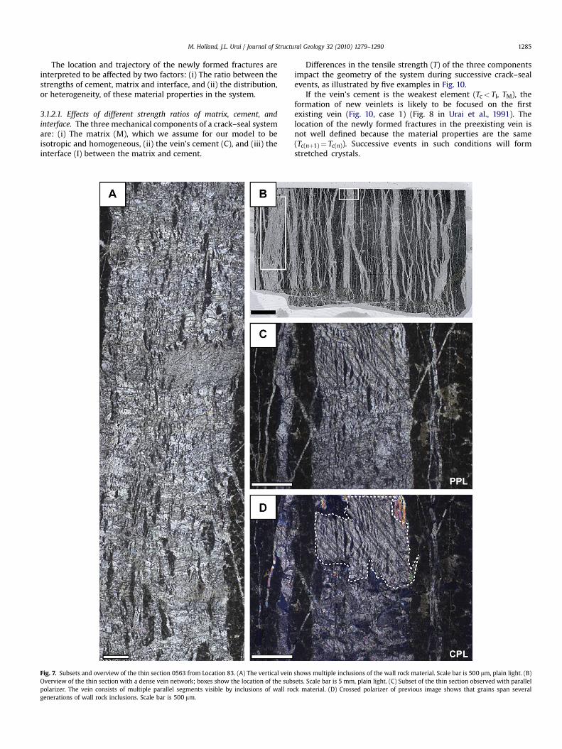
The thick veins show sub-parallel arrays of wall rock inclusions,giving them a laminated appearance (Fig. 7). Branching of veinarrays, or isolated veinlets, from the thick bundles is apparent(Figs. 5 and 7). When segments of isolated veins form an obliqueangle to a bundle they show curve shapes towards the contact. Theveinlets thus merge with the bundles rather than abutting or cross-cutting them.
The calcite cement of the vein network is made of blocky calcitegrains with occasional twinning. Fibrous calcite is absent. In thickervein sections, there is no evidence for growth competition normalto the fracture walls as the grain boundaries are approximatelynormal to wall (Hilgers et al., 2001; Nollet et al., 2005; Urai et al.,1991). We found no evidence for grain boundary migrationrecrystallization (Urai et al., 1991).
The individual veinlets consist of calcite grains that stretch fromwall to wall. The length of the grains parallel to the walls is severaltimes the width of the veinlet (Fig. 8A). In braided sections, thecalcite grains commonly extend into the different branches (Fig. 8B)or across the parallel stacks of the solid inclusions.
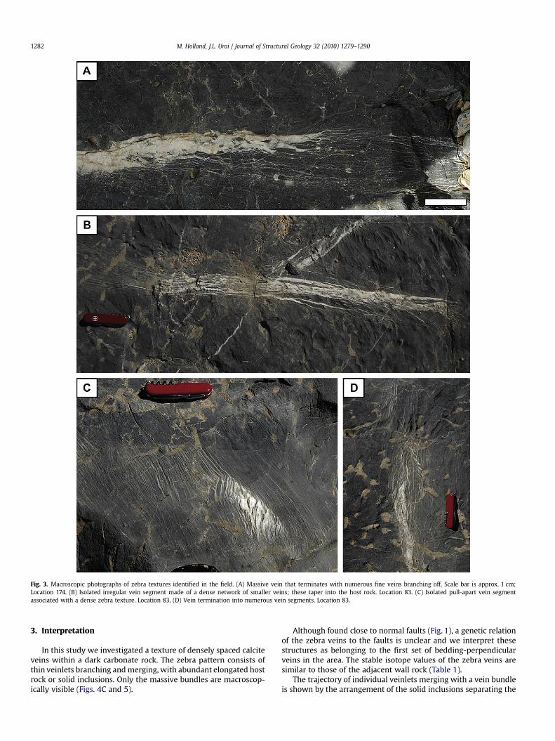
Fig. 3. Macroscopic photographs of zebra textures identified in the field. (A) Massive vein that terminates with numerous fine veins branching off. Scale bar is approx. 1 cm;Location 174. (B) Isolated irregular vein segment made of a dense network of smaller veins; these taper into the host rock. Location 83. (C) Isolated pull-apart vein segmentassociated with a dense zebra texture. Location 83. (D) Vein termination into numerous vein segments. Location 83.
M. Holland, J.L. Urai / Journal of Structural Geology 32 (2010) 1279–12901282
3. Interpretation
In this study we investigated a texture of densely spaced calciteveins within a dark carbonate rock. The zebra pattern consists ofthin veinlets branching and merging, with abundant elongated hostrock or solid inclusions. Only the massive bundles are macroscop-ically visible (Figs. 4C and 5).
Although found close to normal faults (Fig. 1), a genetic relationof the zebra veins to the faults is unclear and we interpret thesestructures as belonging to the first set of bedding-perpendicularveins in the area. The stable isotope values of the zebra veins aresimilar to those of the adjacent wall rock (Table 1).
The trajectory of individual veinlets merging with a vein bundleis shown by the arrangement of the solid inclusions separating the
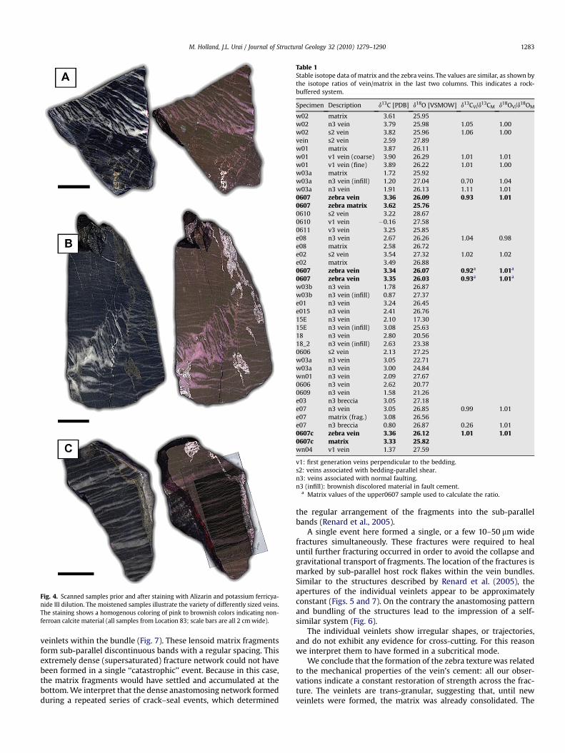
Fig. 4. Scanned samples prior and after staining with Alizarin and potassium ferricya-nide III dilution. The moistened samples illustrate the variety of differently sized veins.The staining shows a homogenous coloring of pink to brownish colors indicating non-ferroan calcite material (all samples from Location 83; scale bars are all 2 cm wide).
Table 1Stable isotope data of matrix and the zebra veins. The values are similar, as shown bythe isotope ratios of vein/matrix in the last two columns. This indicates a rock-buffered system.
Specimen Description d13C [PDB] d18O [VSMOW] d13CV/d13CM d18OV/d18OM
w02 matrix 3.61 25.95w02 n3 vein 3.79 25.98 1.05 1.00w02 s2 vein 3.82 25.96 1.06 1.00vein s2 vein 2.59 27.89w01 matrix 3.87 26.11w01 v1 vein (coarse) 3.90 26.29 1.01 1.01w01 v1 vein (fine) 3.89 26.22 1.01 1.00w03a matrix 1.72 25.92w03a n3 vein (infill) 1.20 27.04 0.70 1.04w03a n3 vein 1.91 26.13 1.11 1.010607 zebra vein 3.36 26.09 0.93 1.010607 zebra matrix 3.62 25.760610 s2 vein 3.22 28.670610 v1 vein �0.16 27.580611 v3 vein 3.25 25.85e08 n3 vein 2.67 26.26 1.04 0.98e08 matrix 2.58 26.72e02 s2 vein 3.54 27.32 1.02 1.02e02 matrix 3.49 26.880607 zebra vein 3.34 26.07 0.92a 1.01a
0607 zebra vein 3.35 26.03 0.93a 1.01a
w03b n3 vein 1.78 26.87w03b n3 vein (infill) 0.87 27.37e01 n3 vein 3.24 26.45e015 n3 vein 2.41 26.7615E n3 vein 2.10 17.3015E n3 vein (infill) 3.08 25.6318 n3 vein 2.80 20.5618_2 n3 vein (infill) 2.63 23.380606 s2 vein 2.13 27.25w03a n3 vein 3.05 22.71w03a n3 vein 3.00 24.84wn01 n3 vein 2.09 27.670606 n3 vein 2.62 20.770609 n3 vein 1.58 21.26e03 n3 breccia 3.05 27.18e07 n3 vein 3.05 26.85 0.99 1.01e07 matrix (frag.) 3.08 26.56e07 n3 breccia 0.80 26.87 0.26 1.010607c zebra vein 3.36 26.12 1.01 1.010607c matrix 3.33 25.82wn04 v1 vein 1.37 27.59
v1: first generation veins perpendicular to the bedding.s2: veins associated with bedding-parallel shear.n3: veins associated with normal faulting.n3 (infill): brownish discolored material in fault cement.
a Matrix values of the upper0607 sample used to calculate the ratio.
M. Holland, J.L. Urai / Journal of Structural Geology 32 (2010) 1279–1290 1283
veinlets within the bundle (Fig. 7). These lensoid matrix fragmentsform sub-parallel discontinuous bands with a regular spacing. Thisextremely dense (supersaturated) fracture network could not havebeen formed in a single ‘‘catastrophic’’ event. Because in this case,the matrix fragments would have settled and accumulated at thebottom. We interpret that the dense anastomosing network formedduring a repeated series of crack–seal events, which determined
the regular arrangement of the fragments into the sub-parallelbands (Renard et al., 2005).
A single event here formed a single, or a few 10–50 mm widefractures simultaneously. These fractures were required to healuntil further fracturing occurred in order to avoid the collapse andgravitational transport of fragments. The location of the fractures ismarked by sub-parallel host rock flakes within the vein bundles.Similar to the structures described by Renard et al. (2005), theapertures of the individual veinlets appear to be approximatelyconstant (Figs. 5 and 7). On the contrary the anastomosing patternand bundling of the structures lead to the impression of a self-similar system (Fig. 6).
The individual veinlets show irregular shapes, or trajectories,and do not exhibit any evidence for cross-cutting. For this reasonwe interpret them to have formed in a subcritical mode.
We conclude that the formation of the zebra texture was relatedto the mechanical properties of the vein’s cement: all our obser-vations indicate a constant restoration of strength across the frac-ture. The veinlets are trans-granular, suggesting that, until newveinlets were formed, the matrix was already consolidated. The
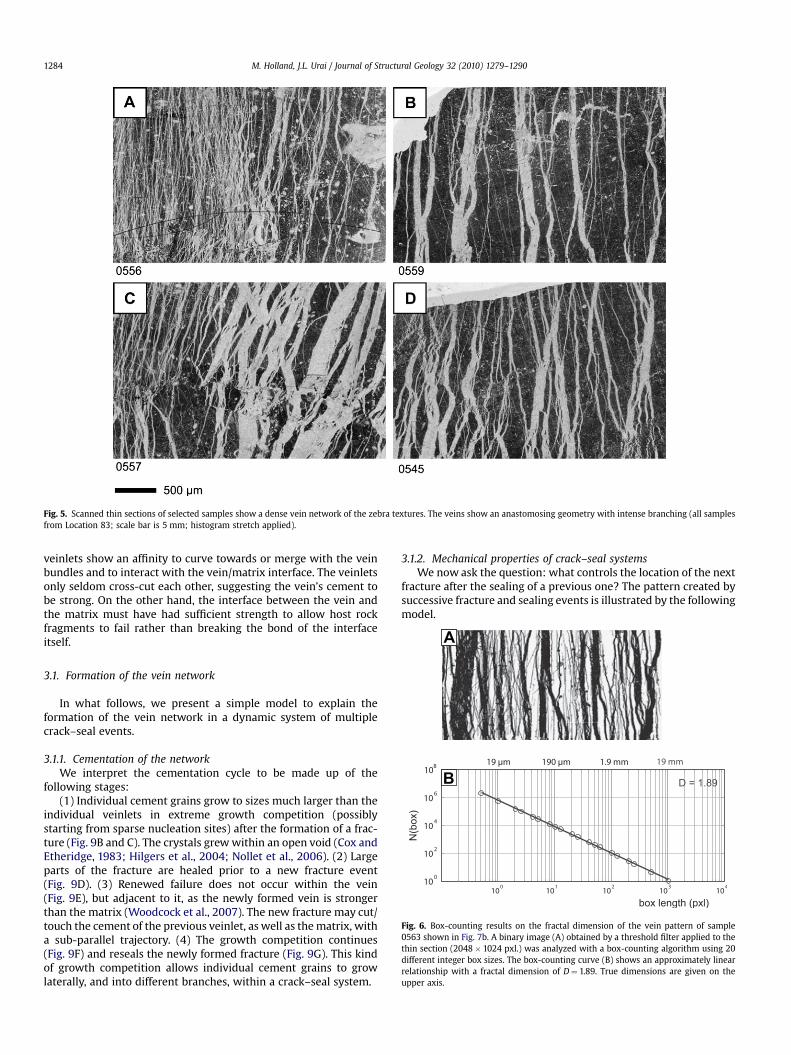
Fig. 5. Scanned thin sections of selected samples show a dense vein network of the zebra textures. The veins show an anastomosing geometry with intense branching (all samplesfrom Location 83; scale bar is 5 mm; histogram stretch applied).
A
M. Holland, J.L. Urai / Journal of Structural Geology 32 (2010) 1279–12901284
veinlets show an affinity to curve towards or merge with the veinbundles and to interact with the vein/matrix interface. The veinletsonly seldom cross-cut each other, suggesting the vein’s cement tobe strong. On the other hand, the interface between the vein andthe matrix must have had sufficient strength to allow host rockfragments to fail rather than breaking the bond of the interfaceitself.
B
Fig. 6. Box-counting results on the fractal dimension of the vein pattern of sample0563 shown in Fig. 7b. A binary image (A) obtained by a threshold filter applied to thethin section (2048� 1024 pxl.) was analyzed with a box-counting algorithm using 20different integer box sizes. The box-counting curve (B) shows an approximately linearrelationship with a fractal dimension of D¼ 1.89. True dimensions are given on theupper axis.
3.1. Formation of the vein network
In what follows, we present a simple model to explain theformation of the vein network in a dynamic system of multiplecrack–seal events.
3.1.1. Cementation of the networkWe interpret the cementation cycle to be made up of the
following stages:(1) Individual cement grains grow to sizes much larger than the
individual veinlets in extreme growth competition (possiblystarting from sparse nucleation sites) after the formation of a frac-ture (Fig. 9B and C). The crystals grew within an open void (Cox andEtheridge, 1983; Hilgers et al., 2004; Nollet et al., 2006). (2) Largeparts of the fracture are healed prior to a new fracture event(Fig. 9D). (3) Renewed failure does not occur within the vein(Fig. 9E), but adjacent to it, as the newly formed vein is strongerthan the matrix (Woodcock et al., 2007). The new fracture may cut/touch the cement of the previous veinlet, as well as the matrix, witha sub-parallel trajectory. (4) The growth competition continues(Fig. 9F) and reseals the newly formed fracture (Fig. 9G). This kindof growth competition allows individual cement grains to growlaterally, and into different branches, within a crack–seal system.
3.1.2. Mechanical properties of crack–seal systemsWe now ask the question: what controls the location of the next
fracture after the sealing of a previous one? The pattern created bysuccessive fracture and sealing events is illustrated by the followingmodel.
M. Holland, J.L. Urai / Journal of Structural Geology 32 (2010) 1279–1290 1285
The location and trajectory of the newly formed fractures areinterpreted to be affected by two factors: (i) The ratio between thestrengths of cement, matrix and interface, and (ii) the distribution,or heterogeneity, of these material properties in the system.
3.1.2.1. Effects of different strength ratios of matrix, cement, andinterface. The three mechanical components of a crack–seal systemare: (i) The matrix (M), which we assume for our model to beisotropic and homogeneous, (ii) the vein’s cement (C), and (iii) theinterface (I) between the matrix and cement.
Fig. 7. Subsets and overview of the thin section 0563 from Location 83. (A) The vertical veinOverview of the thin section with a dense vein network; boxes show the location of the subpolarizer. The vein consists of multiple parallel segments visible by inclusions of wall rogenerations of wall rock inclusions. Scale bar is 500 mm.
Differences in the tensile strength (T) of the three componentsimpact the geometry of the system during successive crack–sealevents, as illustrated by five examples in Fig. 10.
If the vein’s cement is the weakest element (Tc< TI, TM), theformation of new veinlets is likely to be focused on the firstexisting vein (Fig. 10, case 1) (Fig. 8 in Urai et al., 1991). Thelocation of the newly formed fractures in the preexisting vein isnot well defined because the material properties are the same(Tc(nþ1)¼ Tc(n)). Successive events in such conditions will formstretched crystals.
shows multiple inclusions of the wall rock material. Scale bar is 500 mm, plain light. (B)sets. Scale bar is 5 mm, plain light. (C) Subset of the thin section observed with parallelck material. (D) Crossed polarizer of previous image shows that grains span several
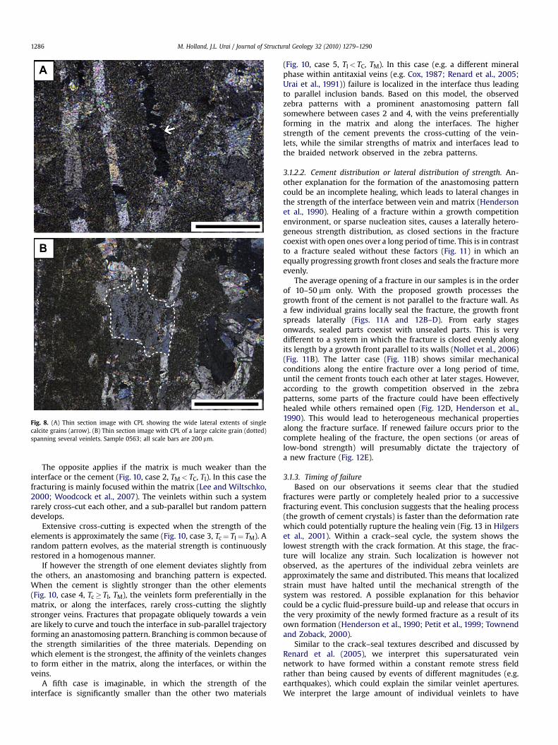
Fig. 8. (A) Thin section image with CPL showing the wide lateral extents of singlecalcite grains (arrow). (B) Thin section image with CPL of a large calcite grain (dotted)spanning several veinlets. Sample 0563; all scale bars are 200 mm.
M. Holland, J.L. Urai / Journal of Structural Geology 32 (2010) 1279–12901286
The opposite applies if the matrix is much weaker than theinterface or the cement (Fig. 10, case 2, TM< TC, TI). In this case thefracturing is mainly focused within the matrix (Lee and Wiltschko,2000; Woodcock et al., 2007). The veinlets within such a systemrarely cross-cut each other, and a sub-parallel but random patterndevelops.
Extensive cross-cutting is expected when the strength of theelements is approximately the same (Fig. 10, case 3, Tc¼ TI¼ TM). Arandom pattern evolves, as the material strength is continuouslyrestored in a homogenous manner.
If however the strength of one element deviates slightly fromthe others, an anastomosing and branching pattern is expected.When the cement is slightly stronger than the other elements(Fig. 10, case 4, Tc� TI, TM), the veinlets form preferentially in thematrix, or along the interfaces, rarely cross-cutting the slightlystronger veins. Fractures that propagate obliquely towards a veinare likely to curve and touch the interface in sub-parallel trajectoryforming an anastomosing pattern. Branching is common because ofthe strength similarities of the three materials. Depending onwhich element is the strongest, the affinity of the veinlets changesto form either in the matrix, along the interfaces, or within theveins.
A fifth case is imaginable, in which the strength of theinterface is significantly smaller than the other two materials
(Fig. 10, case 5, TI< TC, TM). In this case (e.g. a different mineralphase within antitaxial veins (e.g. Cox, 1987; Renard et al., 2005;Urai et al., 1991)) failure is localized in the interface thus leadingto parallel inclusion bands. Based on this model, the observedzebra patterns with a prominent anastomosing pattern fallsomewhere between cases 2 and 4, with the veins preferentiallyforming in the matrix and along the interfaces. The higherstrength of the cement prevents the cross-cutting of the vein-lets, while the similar strengths of matrix and interfaces lead tothe braided network observed in the zebra patterns.
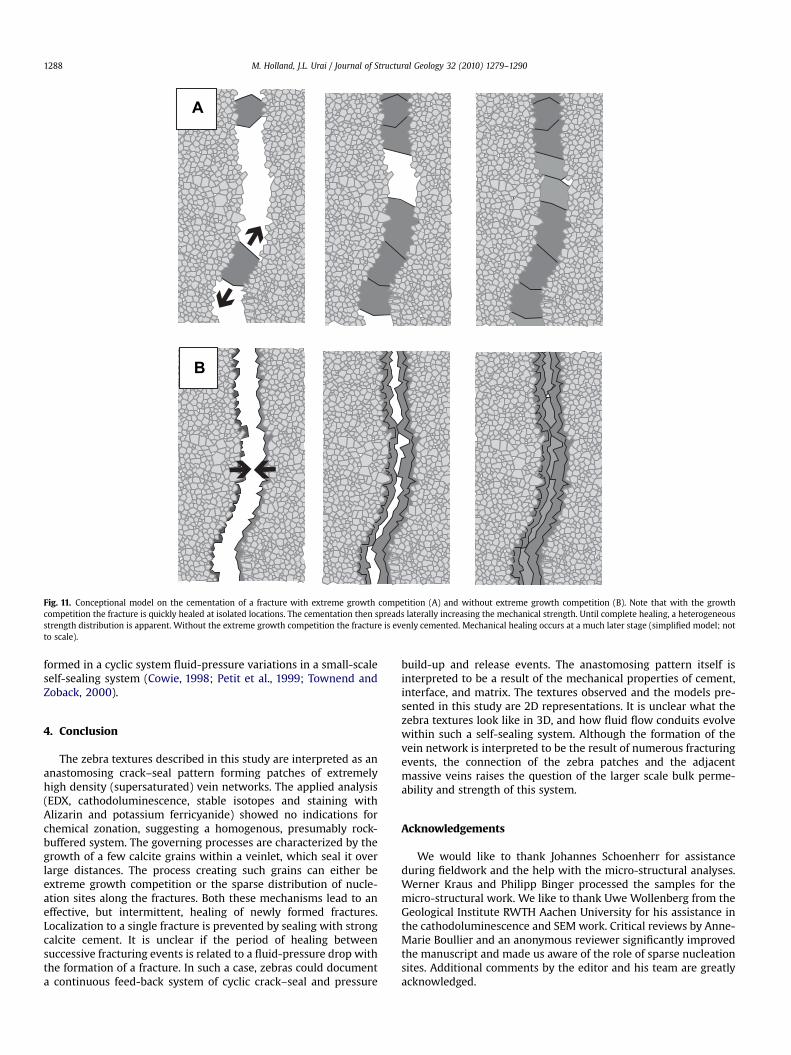
3.1.2.2. Cement distribution or lateral distribution of strength. An-other explanation for the formation of the anastomosing patterncould be an incomplete healing, which leads to lateral changes inthe strength of the interface between vein and matrix (Hendersonet al., 1990). Healing of a fracture within a growth competitionenvironment, or sparse nucleation sites, causes a laterally hetero-geneous strength distribution, as closed sections in the fracturecoexist with open ones over a long period of time. This is in contrastto a fracture sealed without these factors (Fig. 11) in which anequally progressing growth front closes and seals the fracture moreevenly.
The average opening of a fracture in our samples is in the orderof 10–50 mm only. With the proposed growth processes thegrowth front of the cement is not parallel to the fracture wall. Asa few individual grains locally seal the fracture, the growth frontspreads laterally (Figs. 11A and 12B–D). From early stagesonwards, sealed parts coexist with unsealed parts. This is verydifferent to a system in which the fracture is closed evenly alongits length by a growth front parallel to its walls (Nollet et al., 2006)(Fig. 11B). The latter case (Fig. 11B) shows similar mechanicalconditions along the entire fracture over a long period of time,until the cement fronts touch each other at later stages. However,according to the growth competition observed in the zebrapatterns, some parts of the fracture could have been effectivelyhealed while others remained open (Fig. 12D, Henderson et al.,1990). This would lead to heterogeneous mechanical propertiesalong the fracture surface. If renewed failure occurs prior to thecomplete healing of the fracture, the open sections (or areas oflow-bond strength) will presumably dictate the trajectory ofa new fracture (Fig. 12E).
3.1.3. Timing of failureBased on our observations it seems clear that the studied
fractures were partly or completely healed prior to a successivefracturing event. This conclusion suggests that the healing process(the growth of cement crystals) is faster than the deformation ratewhich could potentially rupture the healing vein (Fig. 13 in Hilgerset al., 2001). Within a crack–seal cycle, the system shows thelowest strength with the crack formation. At this stage, the frac-ture will localize any strain. Such localization is however notobserved, as the apertures of the individual zebra veinlets areapproximately the same and distributed. This means that localizedstrain must have halted until the mechanical strength of thesystem was restored. A possible explanation for this behaviorcould be a cyclic fluid-pressure build-up and release that occurs inthe very proximity of the newly formed fracture as a result of itsown formation (Henderson et al., 1990; Petit et al., 1999; Townendand Zoback, 2000).
Similar to the crack–seal textures described and discussed byRenard et al. (2005), we interpret this supersaturated veinnetwork to have formed within a constant remote stress fieldrather than being caused by events of different magnitudes (e.g.earthquakes), which could explain the similar veinlet apertures.We interpret the large amount of individual veinlets to have
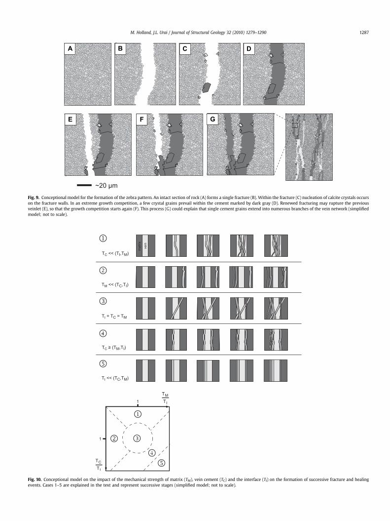
Fig. 10. Conceptional model on the impact of the mechanical strength of matrix (TM), vein cement (TC) and the interface (TI) on the formation of successive fracture and healingevents. Cases 1–5 are explained in the text and represent successive stages (simplified model; not to scale).
A B C
GFE
D
Fig. 9. Conceptional model for the formation of the zebra pattern. An intact section of rock (A) forms a single fracture (B). Within the fracture (C) nucleation of calcite crystals occurson the fracture walls. In an extreme growth competition, a few crystal grains prevail within the cement marked by dark gray (D). Renewed fracturing may rupture the previousveinlet (E), so that the growth competition starts again (F). This process (G) could explain that single cement grains extend into numerous branches of the vein network (simplifiedmodel; not to scale).
M. Holland, J.L. Urai / Journal of Structural Geology 32 (2010) 1279–1290 1287
A
B
Fig. 11. Conceptional model on the cementation of a fracture with extreme growth competition (A) and without extreme growth competition (B). Note that with the growthcompetition the fracture is quickly healed at isolated locations. The cementation then spreads laterally increasing the mechanical strength. Until complete healing, a heterogeneousstrength distribution is apparent. Without the extreme growth competition the fracture is evenly cemented. Mechanical healing occurs at a much later stage (simplified model; notto scale).
M. Holland, J.L. Urai / Journal of Structural Geology 32 (2010) 1279–12901288
formed in a cyclic system fluid-pressure variations in a small-scaleself-sealing system (Cowie, 1998; Petit et al., 1999; Townend andZoback, 2000).
4. Conclusion
The zebra textures described in this study are interpreted as ananastomosing crack–seal pattern forming patches of extremelyhigh density (supersaturated) vein networks. The applied analysis(EDX, cathodoluminescence, stable isotopes and staining withAlizarin and potassium ferricyanide) showed no indications forchemical zonation, suggesting a homogenous, presumably rock-buffered system. The governing processes are characterized by thegrowth of a few calcite grains within a veinlet, which seal it overlarge distances. The process creating such grains can either beextreme growth competition or the sparse distribution of nucle-ation sites along the fractures. Both these mechanisms lead to aneffective, but intermittent, healing of newly formed fractures.Localization to a single fracture is prevented by sealing with strongcalcite cement. It is unclear if the period of healing betweensuccessive fracturing events is related to a fluid-pressure drop withthe formation of a fracture. In such a case, zebras could documenta continuous feed-back system of cyclic crack–seal and pressure
build-up and release events. The anastomosing pattern itself isinterpreted to be a result of the mechanical properties of cement,interface, and matrix. The textures observed and the models pre-sented in this study are 2D representations. It is unclear what thezebra textures look like in 3D, and how fluid flow conduits evolvewithin such a self-sealing system. Although the formation of thevein network is interpreted to be the result of numerous fracturingevents, the connection of the zebra patches and the adjacentmassive veins raises the question of the larger scale bulk perme-ability and strength of this system.
Acknowledgements
We would like to thank Johannes Schoenherr for assistanceduring fieldwork and the help with the micro-structural analyses.Werner Kraus and Philipp Binger processed the samples for themicro-structural work. We like to thank Uwe Wollenberg from theGeological Institute RWTH Aachen University for his assistance inthe cathodoluminescence and SEM work. Critical reviews by Anne-Marie Boullier and an anonymous reviewer significantly improvedthe manuscript and made us aware of the role of sparse nucleationsites. Additional comments by the editor and his team are greatlyacknowledged.
BA C
D E F
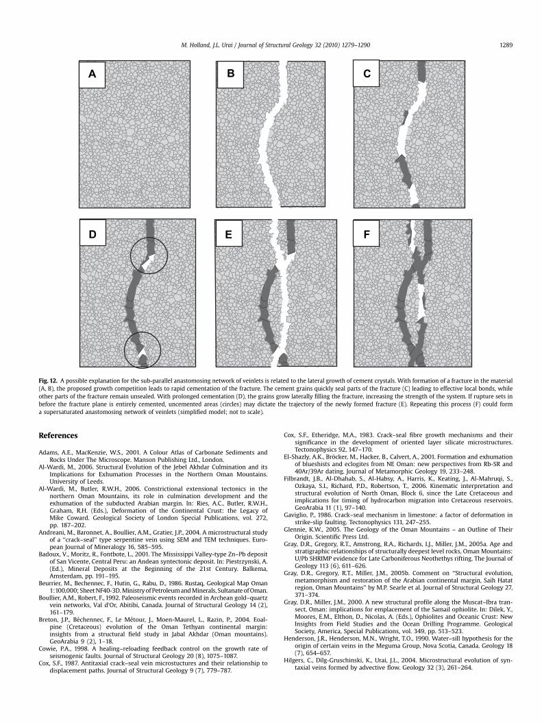
Fig. 12. A possible explanation for the sub-parallel anastomosing network of veinlets is related to the lateral growth of cement crystals. With formation of a fracture in the material(A, B), the proposed growth competition leads to rapid cementation of the fracture. The cement grains quickly seal parts of the fracture (C) leading to effective local bonds, whileother parts of the fracture remain unsealed. With prolonged cementation (D), the grains grow laterally filling the fracture, increasing the strength of the system. If rupture sets inbefore the fracture plane is entirely cemented, uncemented areas (circles) may dictate the trajectory of the newly formed fracture (E). Repeating this process (F) could forma supersaturated anastomosing network of veinlets (simplified model; not to scale).
M. Holland, J.L. Urai / Journal of Structural Geology 32 (2010) 1279–1290 1289
References
Adams, A.E., MacKenzie, W.S., 2001. A Colour Atlas of Carbonate Sediments andRocks Under The Microscope. Manson Publishing Ltd., London.
Al-Wardi, M., 2006. Structural Evolution of the Jebel Akhdar Culmination and itsImplications for Exhumation Processes in the Northern Oman Mountains.University of Leeds.
Al-Wardi, M., Butler, R.W.H., 2006. Constrictional extensional tectonics in thenorthern Oman Mountains, its role in culmination development and theexhumation of the subducted Arabian margin. In: Ries, A.C., Butler, R.W.H.,Graham, R.H. (Eds.), Deformation of the Continental Crust: the Legacy ofMike Coward. Geological Society of London Special Publications, vol. 272,pp. 187–202.
Andreani, M., Baronnet, A., Boullier, A.M., Gratier, J.P., 2004. A microstructural studyof a ‘‘crack–seal’’ type serpentine vein using SEM and TEM techniques. Euro-pean Journal of Mineralogy 16, 585–595.
Badoux, V., Moritz, R., Fontbote, L., 2001. The Mississippi Valley-type Zn–Pb depositof San Vicente, Central Peru: an Andean syntectonic deposit. In: Piestrzynski, A.(Ed.), Mineral Deposits at the Beginning of the 21st Century. Balkema,Amsterdam, pp. 191–195.
Beurrier, M., Bechennec, F., Hutin, G., Rabu, D., 1986. Rustaq, Geological Map Oman1:100,000; Sheet NF40-3D. Ministry of Petroleum and Minerals, Sultanate of Oman.
Boullier, A.M., Robert, F., 1992. Paleoseismic events recorded in Archean gold–quartzvein networks, Val d’Or, Abitibi, Canada. Journal of Structural Geology 14 (2),161–179.
Breton, J.P., Bechennec, F., Le Metour, J., Moen-Maurel, L., Razin, P., 2004. Eoal-pine (Cretaceous) evolution of the Oman Tethyan continental margin:insights from a structural field study in Jabal Akhdar (Oman mountains).GeoArabia 9 (2), 1–18.
Cowie, P.A., 1998. A healing–reloading feedback control on the growth rate ofseismogenic faults. Journal of Structural Geology 20 (8), 1075–1087.
Cox, S.F., 1987. Antitaxial crack–seal vein microstuctures and their relationship todisplacement paths. Journal of Structural Geology 9 (7), 779–787.
Cox, S.F., Etheridge, M.A., 1983. Crack–seal fibre growth mechanisms and theirsignificance in the development of oriented layer silicate microstructures.Tectonophysics 92, 147–170.
El-Shazly, A.K., Brocker, M., Hacker, B., Calvert, A., 2001. Formation and exhumationof blueshists and eclogites from NE Oman: new perspectives from Rb-SR and40Ar/39Ar dating. Journal of Metamorphic Geology 19, 233–248.
Filbrandt, J.B., Al-Dhahab, S., Al-Habsy, A., Harris, K., Keating, J., Al-Mahruqi, S.,Ozkaya, S.I., Richard, P.D., Robertson, T., 2006. Kinematic interpretation andstructural evolution of North Oman, Block 6, since the Late Cretaceous andimplications for timing of hydrocarbon migration into Cretaceous reservoirs.GeoArabia 11 (1), 97–140.
Gaviglio, P., 1986. Crack–seal mechanism in limestone: a factor of deformation instrike-slip faulting. Tectonophysics 131, 247–255.
Glennie, K.W., 2005. The Geology of the Oman Mountains – an Outline of TheirOrigin. Scientific Press Ltd.
Gray, D.R., Gregory, R.T., Amstrong, R.A., Richards, I.J., Miller, J.M., 2005a. Age andstratigraphic relationships of structurally deepest level rocks, Oman Mountains:U/Pb SHRIMP evidence for Late Carboniferous Neothethys rifting. The Journal ofGeology 113 (6), 611–626.
Gray, D.R., Gregory, R.T., Miller, J.M., 2005b. Comment on ‘‘Structural evolution,metamorphism and restoration of the Arabian continental margin, Saih Hatatregion, Oman Mountains’’ by M.P. Searle et al. Journal of Structural Geology 27,371–374.
Gray, D.R., Miller, J.M., 2000. A new structural profile along the Muscat–Ibra tran-sect, Oman: implications for emplacement of the Samail ophiolite. In: Dilek, Y.,Moores, E.M., Elthon, D., Nicolas, A. (Eds.), Ophiolites and Oceanic Crust: NewInsights from Field Studies and the Ocean Drilling Programme. GeologicalSociety, America, Special Publications, vol. 349, pp. 513–523.
Henderson, J.R., Henderson, M.N., Wright, T.O., 1990. Water–sill hypothesis for theorigin of certain veins in the Meguma Group, Nova Scotia, Canada. Geology 18(7), 654–657.
Hilgers, C., Dilg-Gruschinski, K., Urai, J.L., 2004. Microstructural evolution of syn-taxial veins formed by advective flow. Geology 32 (3), 261–264.
M. Holland, J.L. Urai / Journal of Structural Geology 32 (2010) 1279–12901290
Hilgers, C., Kirschner, D.L., Breton, J.P., Urai, J.L., 2006. Fracture sealing in a regional,high-pressure cell in Jabal Akhdar, Oman mountains – first results. Geofluids 6 (2).
Hilgers, C., Koehn, D., Bons, P.D., Urai, J.L., 2001. Developent of crystal morphologyduring unitaxial growth in a progressively widening vein: II. Numerical simu-lations of the evolution of antitaxial fibrous veins. Journal of Structural Geology23, 873–885.
Hilgers, C., Urai, J.L., 2005. On the arrangement of solid inclusions in fibrous veinsand the role of the crack–seal mechanism. Journal of Structural Geology 27 (3),481–494.
Marc Holland, Janos L. Urai, Philippe Muchez and Emanuel J.M. Willemse (2009),Evolution of fractures in a highly dynamic, thermal, hydraulic, and mechanicalsystem - (I) Field observations in Mesozoic Carbonates, Jabal Shams, OmanMountains, GeoArabia, vol. 14, No. 1, p.57–110.
Marc Holland, Nishank Saxena and Janos L. Urai (in press), Evolution of fractures ina highly dynamic thermal, hydraulic, and mechanical system - (II) Remotesensing fracture analysis, Jabal Shams, Oman Mountains, GeoArabia, v. 14, No. 3,2009, p. 163-194.
Hughes Clarke, M.W., 1988. Stratigraphy and rock unit nomenclature in the oil-producing area of interior Oman. Journal of Petroleum Geology 11 (1), 5–60.
Kraus, W., 2002a. ATP Reagenz und Lamipeel. Der Praparator 48 (2), 51–75.Kraus, W., 2002b. Lamipeel-Praparation: Eine neue effiziente Methode zur Struk-
turdokumentation von Karbonat-Bohrkernproben. Mitt. Ing. u. Hydrogeol., 80.Kusky, T., Robinson, C., El-Baz, F., 2005. Tertiary–Quaternary faulting and uplift in the
northern Oman Hajar Mountains. Journal of the Geological Society 162 (5),871–888.Lee, Y.J.Y.J., Wiltschko, D.V., 2000. Fault controlled sequential vein dilation:
competition between slip and precipitation rates in the Austin Chalk, Texas.Journal of Structural Geology 22 (9), 1247–1260.
Loosveld, R.J.H., Bell, A., Terken, J.J.M., 1996. The tectonic evolution of interior Oman.GeoArabia 1 (1), 28–51.
Merino, E., Canals, A, Fletcher, R.C., 2006. Genesis of self-organized zebra textures inburial dolomites: displacive veins, induced stress, and dolomitization. Geo-logica Acta 4 (3), 383–393.
Nielsen, P., Flipkens, V., Groessens, E., Swennen, R., 2000. Sedimentology anddiagenesis of the Dinantian succession in the Vinalmont Borehole. GeologicaBelgica 3 (3–4), 369–393.
Nielsen, P., Swennen, R., Muchez, P., Keppens, E., 1998. Origin of Dinantian zebra dolo-mites south of the Brabant–Wales Massif, Belgium. Sedimentology 45, 737–743.
Nollet, S., Hilgers, C., Urai, J.L., 2006. Experimental study of polycrystal growth froman advecting supersaturated fluid in a model fracture. Geofluids 6, 185–200.
Nollet, S., Urai, J.L., Bons, P.D., Hilgers, C., 2005. Numerical simulations of polycrystalgrowth in veins. Journal of Structural Geology 27 (2), 217–230.
Patton, T.L., O’Conner, S., 1988. Cretaceous flexural history of the northern OmanMountains foredeep, United Arab Emirates. Bulletin of American Association ofPetroleum Geologists 72, 797–807.
Petit, J.P., Wibberley, C.A.J., Ruiz, G., 1999. ‘Crack–seal’, slip: a new fault valvemechanism? Journal of Structural Geology 21 (8–9), 1199–1207.
Ramsay, J.G., 1980. The crack–seal mechanism of rock deformation. Nature 284(5752), 135–139.
Renard, F., Andreani, M., Boullier, A.M., Labaume, P., 2005. Crack–seal patterns;records of uncorrelated stress release variations in crustal rocks. In: Gapais, D.,Brun, J.P., Cobbold, P.R. (Eds.), Deformation, Mechanisms, Rheology andTectonics: From Mineral to the Lithosphere. Geological Society, London, SpecialPublications, vol. 243, pp. 67–79. United Kingdom.
Searle, M.P., 2007. Structural geometry, style and timing of deformation in theHawasina Window, Al Jabal al Akhdar and Saih Hatat culminations, OmanMountains. GeoArabia 12 (2), 99–130.
Searle, M.P., 2007. Structural geometry, style and timing of deformation in theHawasina Window, Al Jabal al Akhdar and Saih Hatat culminations, OmanMountains. GeoArabia 12 (2), 99–130.
Searle, M.P., Warren, C.J., Parrish, R.R., 2005. Reply to: Comment by Gray, Gregoryand Miller on ‘‘Structural evolution, metamorphism and restoration of theArabian continental margin, Saih Hatat region, Oman Mountains’’. Journal ofStructural Geology 27, 375–377.
Swennen, R.A.J., Vandeginste, V., Ellam, R., 2003. Genesis of zebra dolomites(Cathedral formation; Canadian Cordillera fold and thrust belt, BritishColumbia). Journal of Geochemical Exploration 78–79, 571–577.
Townend, J., Zoback, M.D., 2000. How faulting keeps the crust strong. Geology 28(5), 399–402.
Urai, J.L., Williams, P.F., van Roermund, H.L.M., 1991. Kinematics of crystal growth insyntectonic fibrous veins. Journal of Structural Geology 13 (7), 823–836.
Vandeginste, V., Swennen, R., Gleeson, S.A., Ellam, R.M., Osadetz, K., Roure, F., 2005.Zebra dolomitization as a result of focused fluid flow in the Rocky MountainsFold and Thrust Belt, Canada. Sedimentology 52 (5), 1067–1095.
Walsh, J.J., Watterson, J., 1993. Fractal analysis of fracture patterns using the stan-dard box-counting technique: valid and invalid methodologies. Journal ofStructural Geology 15 (12), 1509–1512.
Warbuton, J., Burnhill, T.J., Graham, R.H., Isaac, K.P., 1990. The evolution of the OmanMountains foreland basin. In: Robertson, A.H.F., Searle, M.P., Ries, A.C. (Eds.),The Geology and Tectonics of the Oman Region. Geological Society, London,Special Publication No. 49, pp. 419–427.
Warren, C.J., Miller, J.M., 2007. Structural and stratigraphic controls on the originand tectonic history of a subducted continental margin, Oman. Journal ofStructural Geology 29, 541–558.
Warren, C.J., Parrish, R.R., Searle, M.P., Waters, D.J., 2003. Dating the subduction ofthe Arabian continental margin beneath the Semail ophiolite. Oman. Geology31 (10), 889–892.
Weller, H., 1989. Sedimentologie von Mud Mounds und ihr Nachweis im Harz.Wiss. Z. Ernst-Moritz-Arndt-Univ. Greifswald. Math.nat.wiss. Reihe 38 (1–2),70–78.
Wilson, H.H., 2000. The age of the Hawasina and other problems of Oman MountainGeology. Journal of Petroleum Geology 23 (3), 345–362.
Wiltschko, D.V., Morse, J.W., 2001. Crystallization pressure versus ‘‘crack seal’’ as themechanism for banded veins. Geology 29 (1), 79–82.
Woodcock, N.H., Dickson, J.A.D., Tarasewicz, J.P.T., 2007. Transient permeability andreseal hardening in fault zones: evidence from dilation breccia textures. In:Geological Society, London, Special Publications, vol. 270, pp. 43–53.
Top Related