


Languages
Pages
Legal

Owner’s Operator and Maintenance Manual
DEALER: This manual MUST be given to the user of this product.
USER: BEFORE using this product, read this manual and save for future reference.
For more information regarding Invacare products, parts, and services,
please visit www.invacare.com
Jasmine™ Patient Lift
SYMBOL LEGEND
Jasmine™ Patient Lift 2 Part No 1150704
� WARNINGDO NOT OPERATE THIS EQUIPMENT WITHOUT FIRST READING AND UNDERSTANDING THIS MANUAL. IF YOU ARE UNABLE TO UNDERSTAND THE WARNINGS, CAUTIONS AND INSTRUCTIONS CONTACT A QUALIFIED DEALER OR INVACARE TECHNICAL SUPPORT BEFORE ATTEMPTING TO USE THIS EQUIPMENT - OTHERWISE INJURY OR DAMAGE MAY RESULT.
� ACCESSORIES WARNINGInvacare products are specifically designed and manufactured for use in conjunction with Invac-are accessories. Accessories designed by other manufacturers have not been tested by Invacare and are not recommended for use with Invacare products.
SYMBOL LEGEND
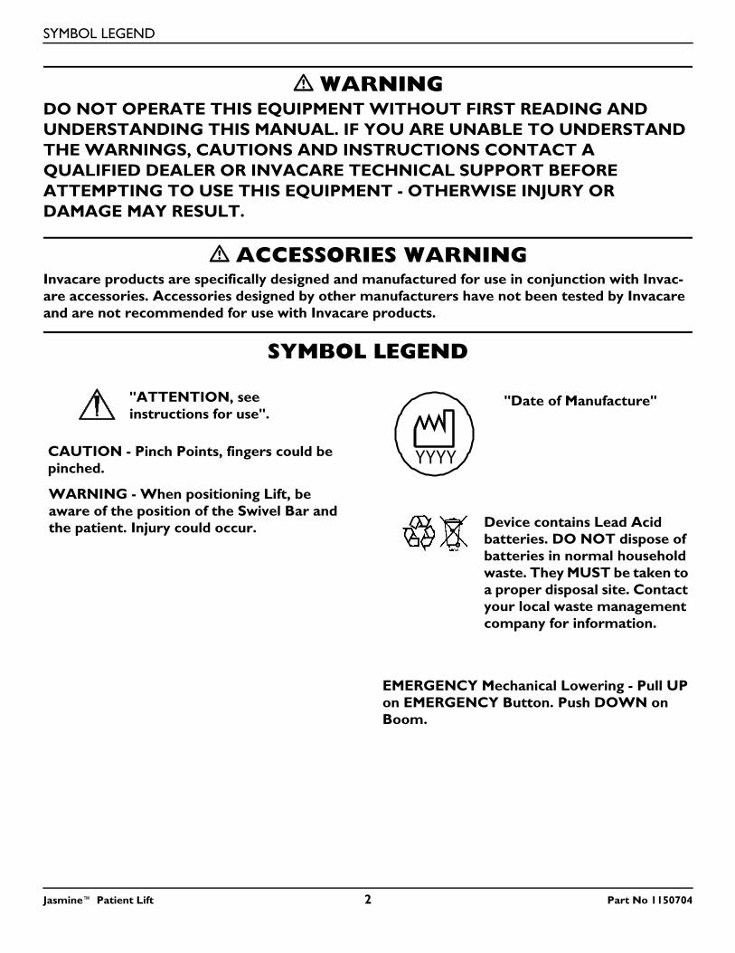
"ATTENTION, see instructions for use".
CAUTION - Pinch Points, fingers could be pinched.
WARNING - When positioning Lift, be aware of the position of the Swivel Bar and the patient. Injury could occur.
"Date of Manufacture"
Device contains Lead Acid batteries. DO NOT dispose of batteries in normal household waste. They MUST be taken to a proper disposal site. Contact your local waste management company for information.
EMERGENCY Mechanical Lowering - Pull UP on EMERGENCY Button. Push DOWN on Boom.
TABLE OF CONTENTS
TABLE OF CONTENTS
SYMBOL LEGEND .............................................................................................. 2SPECIAL NOTES ................................................................................................ 5
LABEL LOCATION ............................................................................................. 6
PRODUCT PARAMETERS .................................................................................. 7
Jasmine Patient Lift .................................................................................................................................................................7
Jasmine Scale JLS5...................................................................................................................................................................7
SECTION 1—GENERAL GUIDELINES ................................................................... 8
Assembling the Lift.................................................................................................................................................................8
Weight Limitation ..................................................................................................................................................................8
Using the Sling.........................................................................................................................................................................8
Operating the Lift...................................................................................................................................................................8
Lifting the Patient ...................................................................................................................................................................9
Transferring the Patient........................................................................................................................................................9
Performing Maintenance.......................................................................................................................................................9
SECTION 2—ASSEMBLY ................................................................................... 10
Assembling the Patient Lift................................................................................................................................................ 10Assembling the Mast Assembly to the Base ............................................................................................................. 10
Attaching the Battery Charger Mounting Bracket to the Wall ................................................................................ 11
Attaching the Battery Charger to the Mast Assembly ............................................................................................... 11
SECTION 3—OPERATION ................................................................................ 12
Operating the Patient Lift.................................................................................................................................................. 12
Locking/Unlocking the Rear Casters.......................................................................................................................... 12Raising/Lowering the Patient Lift................................................................................................................................. 12Closing/Opening the Legs ............................................................................................................................................. 12Using the Emergency Stop............................................................................................................................................ 12Activating a Mechanical Emergency Release............................................................................................................. 13
Charging the Battery .......................................................................................................................................................... 13SECTION 4—LIFTING THE PATIENT ................................................................. 14
Preparing the Lift for Use.................................................................................................................................................. 14
Positioning the Lift for Use........................................................................................................................................... 14Attaching a Sling to the Swivel Bar ............................................................................................................................. 14Attaching a Sling to the Optional Cradle Attachment ........................................................................................... 15
Lifting/Moving the Patient.................................................................................................................................................. 16
SECTION 5—TRANSFERRING THE PATIENT ..................................................... 18
Transferring to a Commode Chair ................................................................................................................................. 18
Transferring to a Standard Commode ........................................................................................................................... 19
Transferring to a Wheelchair ........................................................................................................................................... 19
Part No 1150704 3 Jasmine™ Patient Lift
TABLE OF CONTENTS
TABLE OF CONTENTS
SECTION 6—TROUBLESHOOTING .................................................................... 20SECTION 7—MAINTENANCE ........................................................................... 21
Maintenance Safety Inspection Checklist ....................................................................................................................... 21
Lubricating the Lift .............................................................................................................................................................. 22
Detecting Wear and Damage........................................................................................................................................... 22
Cleaning the Sling and the Lift .......................................................................................................................................... 22
Replacing the Boom Actuator .......................................................................................................................................... 22
Replacing the Leg Actuators ............................................................................................................................................. 24
Replacing the Swivel Bar or Optional Cradle Attachment........................................................................................ 25
Checking and Tightening Mast Pivot............................................................................................................................... 26
SECTION 8—ACCESSORIES .............................................................................. 27
Jasmine Scale JLS5................................................................................................................................................................ 27
Removing the Swivel Bar/Cradle Attachment.......................................................................................................... 27Installing the Jasmine Scale............................................................................................................................................ 28Installing the Swivel Bar or Cradle Attachment ...................................................................................................... 28
Operating the Scale ............................................................................................................................................................ 29
Keypad Functions............................................................................................................................................................ 29
Weighing the Patient .......................................................................................................................................................... 29
Replacing the Battery ......................................................................................................................................................... 30
Calibrating the Jasmine Scale........................................................................................................................................ 31
Troubleshooting .................................................................................................................................................................. 31
Display Codes.................................................................................................................................................................. 31LIMITED WARRANTY ..................................................................................... 34
Jasmine™ Patient Lift 4 Part No 1150704
SPECIAL NOTES
Part No 1150704 5 Jasmine™ Patient Lift
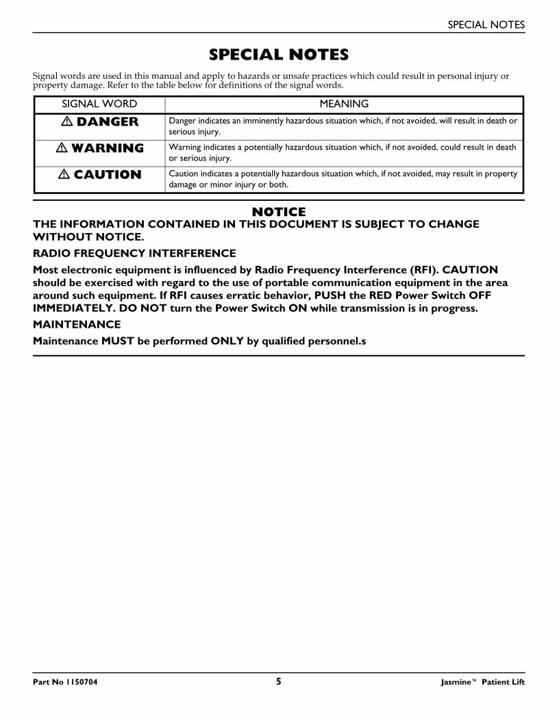
SPECIAL NOTESSignal words are used in this manual and apply to hazards or unsafe practices which could result in personal injury or property damage. Refer to the table below for definitions of the signal words.
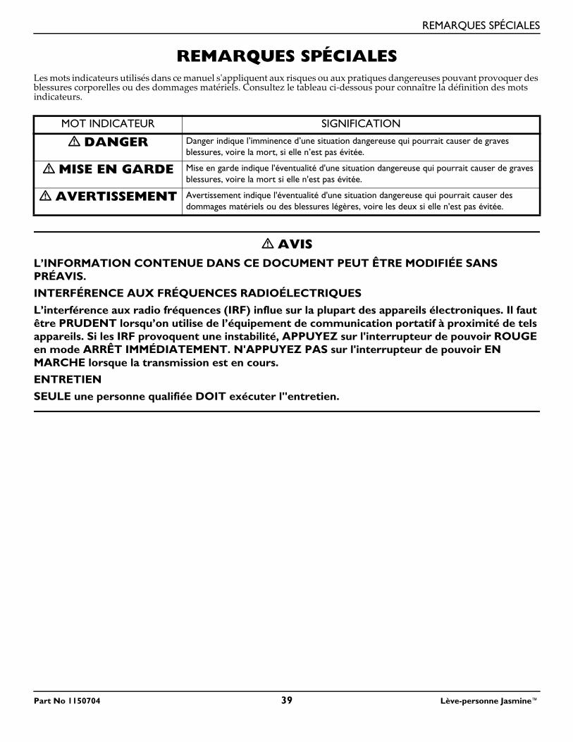
NOTICETHE INFORMATION CONTAINED IN THIS DOCUMENT IS SUBJECT TO CHANGE WITHOUT NOTICE.RADIO FREQUENCY INTERFERENCEMost electronic equipment is influenced by Radio Frequency Interference (RFI). CAUTION should be exercised with regard to the use of portable communication equipment in the area around such equipment. If RFI causes erratic behavior, PUSH the RED Power Switch OFF IMMEDIATELY. DO NOT turn the Power Switch ON while transmission is in progress.MAINTENANCEMaintenance MUST be performed ONLY by qualified personnel.s
SIGNAL WORD MEANING
� DANGER Danger indicates an imminently hazardous situation which, if not avoided, will result in death or serious injury.
� WARNING Warning indicates a potentially hazardous situation which, if not avoided, could result in death or serious injury.
� CAUTION Caution indicates a potentially hazardous situation which, if not avoided, may result in property damage or minor injury or both.
LABEL LOCATION
Jasmine™ Patient Lift 6 Part No 1150704
LABEL LOCATION
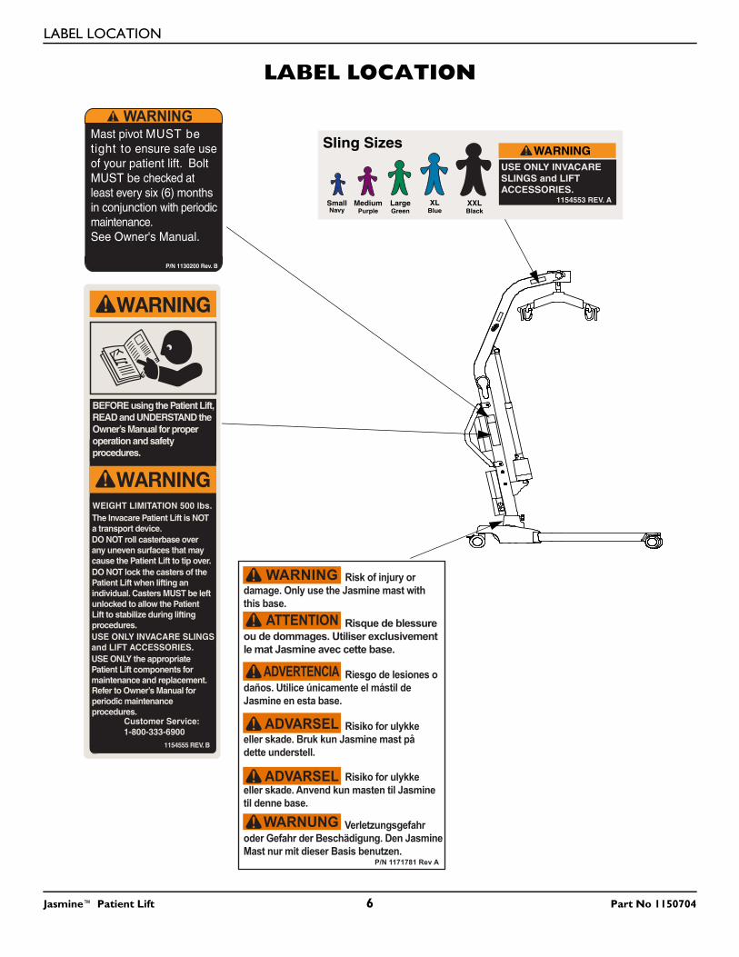
WARNINGMast pivot MUST be tight to ensure safe use of your patient lift. Bolt MUST be checked at least every six (6) months in conjunction with periodicmaintenance.See Owner's Manual.
P/N 1130200 Rev. B
SmallNavy
MediumPurple
LargeGreen
XLBlue
XXLBlack
WARNINGUSE ONLY INVACARE SLINGS and LIFT ACCESSORIES.
Sling Sizes
1154553 REV. A
PRODUCT PARAMETERS
Part No 1150704 7 Jasmine™ Patient Lift
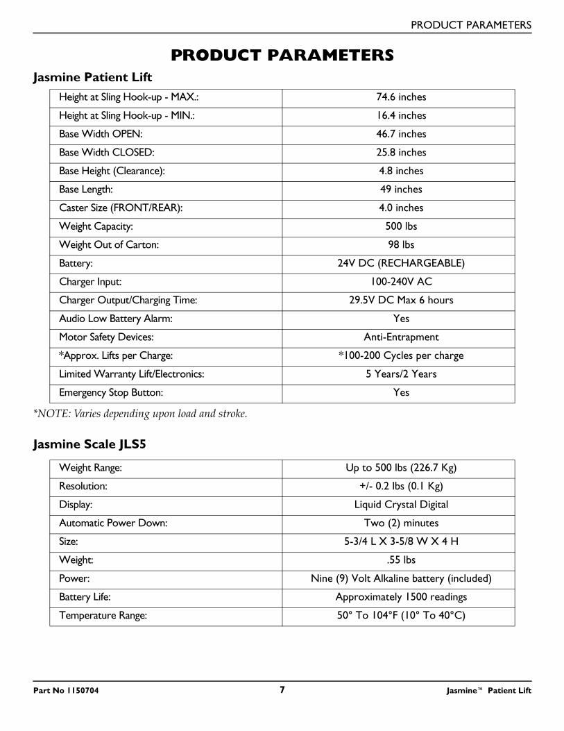
PRODUCT PARAMETERSJasmine Patient Lift
*NOTE: Varies depending upon load and stroke.
Jasmine Scale JLS5
Height at Sling Hook-up - MAX.: 74.6 inches
Height at Sling Hook-up - MIN.: 16.4 inches
Base Width OPEN: 46.7 inches
Base Width CLOSED: 25.8 inches
Base Height (Clearance): 4.8 inches
Base Length: 49 inches
Caster Size (FRONT/REAR): 4.0 inches
Weight Capacity: 500 lbs
Weight Out of Carton: 98 lbs
Battery: 24V DC (RECHARGEABLE)
Charger Input: 100-240V AC
Charger Output/Charging Time: 29.5V DC Max 6 hours
Audio Low Battery Alarm: Yes
Motor Safety Devices: Anti-Entrapment
*Approx. Lifts per Charge: *100-200 Cycles per charge
Limited Warranty Lift/Electronics: 5 Years/2 Years
Emergency Stop Button: Yes
Weight Range: Up to 500 lbs (226.7 Kg)
Resolution: +/- 0.2 lbs (0.1 Kg)
Display: Liquid Crystal Digital
Automatic Power Down: Two (2) minutes
Size: 5-3/4 L X 3-5/8 W X 4 H
Weight: .55 lbs
Power: Nine (9) Volt Alkaline battery (included)
Battery Life: Approximately 1500 readings
Temperature Range: 50° To 104°F (10° To 40°C)
SECTION 1—GENERAL GUIDELINES
SECTION 1—GENERAL GUIDELINES
� WARNINGSECTION 1 - GENERAL GUIDELINES contains important information for the safe operation and use of this product.
Check all parts for shipping damage before using. In case of damage, DO NOT use the equipment. Contact the Dealer for further instructions.The Invacare patient lift is NOT a transport device. It is intended to transfer an individual from one resting surface to another (such as a bed to a wheelchair).DO NOT attempt any transfer without approval of the patient’s physician, nurse or medical assistant. Thoroughly read the instructions in this Owner’s Manual, observe a trained team of experts perform the lifting procedures and then perform the entire lift procedure several times with proper supervision and a capable individual acting as a patient.Invacare slings and patient lift accessories are specifically designed to be used in conjunction with Invacare patient lifts. Slings and accessories designed by other manufacturers are not to be utilized as a component of Invacare’s patient lift system.If the patient lift is used in the area of a shower or bath, ensure that the patient lift is wiped clean of any moisture after use. DO NOT store the lift in a damp area or in a damp condition. Periodically inspect all components of the patient lift for signs of corrosion. Replace all parts that are corroded or damaged.
Assembling the LiftDO NOT overtighten mounting hardware. This will damage mounting brackets.
Weight LimitationDO NOT exceed the maximum weight limitation of the patient lift. The weight limitation for the Jasmine Patient Lift is 500 lbs.
Using the SlingThe Jasmine Patient Lift can be used with the standard swivel bar or an optional cradle attachment. The tilting cradle attachment enables a single caregiver to more easily position a patient in an upright and seated position.Use an Invacare approved sling that is recommended by the individual’s doctor, nurse or medical assistant for the comfort and safety of the individual being lifted.After each laundering (in accordance with instructions on the sling), inspect sling(s) for wear, tears, and loose stitching.Bleached, torn, cut, frayed, or broken slings are unsafe and could result in injury. Discard IMMEDIATELY.DO NOT alter slings.Be sure to check the sling attachments each time the sling is removed and replaced, to ensure that it is properly attached before the patient is removed from a stationary object (bed, chair or commode).If the patient is in a wheelchair, secure the wheel locks in place to prevent the chair from moving forwards or backwards.When connecting slings equipped with color coded straps to the patient lift, the shortest of the straps MUST be at the back of patient for support. Using long section will leave little or no support for patient's back. The loops of the sling are color coded and can be used to place patient in various positions. The colors make it easy to connect both sides of the sling equally. Make sure that there is sufficient head support when lifting a patient.
Operating the LiftAlthough Invacare recommends that two assistants be used for all lifting preparation, transferring from and transferring to procedures, our equipment will permit proper operation by one assistant. The use of one assistant is based on the evaluation of the health care professional for each individual case.Make sure there is an audible click when mounting battery on the battery charger to confirm proper mounting. Otherwise, injury or damage may occur.ALWAYS keep hands and fingers clear of moving parts to avoid injury.
Jasmine™ Patient Lift 8 Part No 1150704
SECTION 1—GENERAL GUIDELINES
Lifting the PatientAdjustments for safety and comfort should be made before moving the patient. Patient's arms should be inside of the straps.Before transferring a patient from a stationary object (wheelchair, commode or bed), slightly raise the patient off the stationary object and check that all sling attachments are secure. If any attachment is not correct, lower the patient and correct the problem, then raise the patient and check again.During transfer, with patient suspended in a sling attached to the lift, DO NOT roll caster base over uneven surfaces that would create an imbalance of the patient lift and could cause the patient lift to tip over. Use steering handle on the mast at ALL times to push or pull the patient lift.
Transferring the PatientBefore transferring, check that the product’s weight capacity can withstand the patient’s weight.Before transferring a patient from a stationary object (wheelchair, commode or bed), slightly raise the patient off the stationary object and check that all sling attachments are secure. If any attachment is not correct, lower the patient and correct the problem, then raise the patient and check again.Before transferring, check that the product that you are transferring the patient to can withstand the patient’s weight.Wheelchair wheel locks MUST be in a locked position before lowering the patient into the wheelchair for transport.Be sure to check the sling attachments each time the sling is removed and replaced, to ensure that it is properly attached before the patient is removed from the bed or chair.The mast pivot bolt MUST be tight to ensure safe use of the patient lift. The bolt MUST be checked at least every six months in conjunction with periodic maintenance.
Performing MaintenanceRegular maintenance of patient lifts and accessories is necessary to assure proper operation.After the first twelve months of operation, inspect all pivot points and fasteners for wear. If the metal is worn, the parts MUST be replaced. Perform this inspection every six months thereafter.Casters and axle bolts require inspections every six months to check for tightness and wear.
Part No 1150704 9 Jasmine™ Patient Lift
SECTION 2—ASSEMBLY
SECTION 2—ASSEMBLY
Assembling the Patient Lift
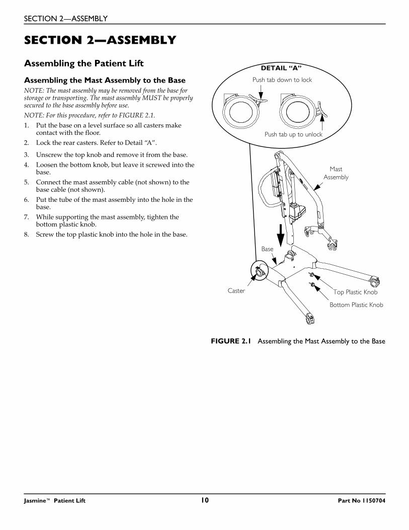
Assembling the Mast Assembly to the BaseNOTE: The mast assembly may be removed from the base for storage or transporting. The mast assembly MUST be properly secured to the base assembly before use.NOTE: For this procedure, refer to FIGURE 2.1.1. Put the base on a level surface so all casters make
contact with the floor.2. Lock the rear casters. Refer to Detail “A”.
3. Unscrew the top knob and remove it from the base.4. Loosen the bottom knob, but leave it screwed into the
base.5. Connect the mast assembly cable (not shown) to the
base cable (not shown).6. Put the tube of the mast assembly into the hole in the
base.7. While supporting the mast assembly, tighten the
bottom plastic knob.8. Screw the top plastic knob into the hole in the base.
FIGURE 2.1 Assembling the Mast Assembly to the Base
Push tab down to lock
Push tab up to unlock
DETAIL “A”
Caster
Mast Assembly
Top Plastic Knob
Base
Bottom Plastic Knob
Jasmine™ Patient Lift 10 Part No 1150704
SECTION 2—ASSEMBLY
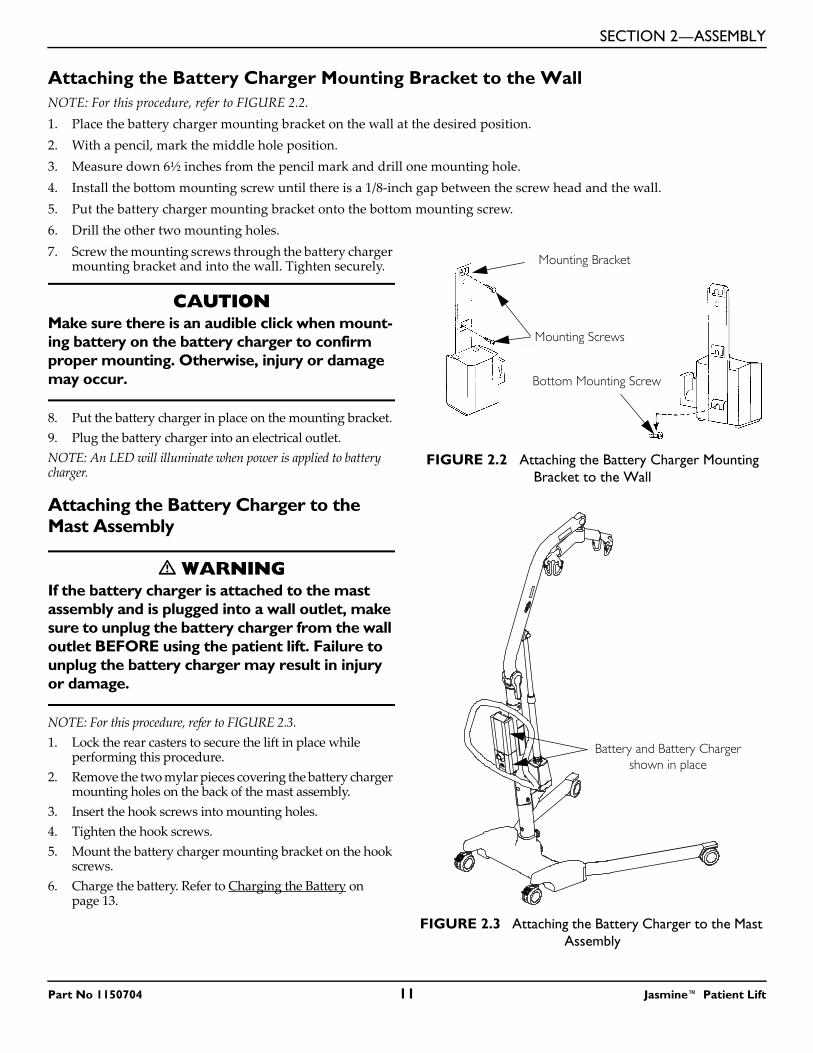
Attaching the Battery Charger Mounting Bracket to the WallNOTE: For this procedure, refer to FIGURE 2.2.1. Place the battery charger mounting bracket on the wall at the desired position.2. With a pencil, mark the middle hole position.3. Measure down 6½ inches from the pencil mark and drill one mounting hole.4. Install the bottom mounting screw until there is a 1/8-inch gap between the screw head and the wall.5. Put the battery charger mounting bracket onto the bottom mounting screw.6. Drill the other two mounting holes.7. Screw the mounting screws through the battery charger
mounting bracket and into the wall. Tighten securely.
CAUTIONMake sure there is an audible click when mount-ing battery on the battery charger to confirm proper mounting. Otherwise, injury or damage may occur.
8. Put the battery charger in place on the mounting bracket.9. Plug the battery charger into an electrical outlet.NOTE: An LED will illuminate when power is applied to battery charger.
Attaching the Battery Charger to the Mast Assembly
� WARNINGIf the battery charger is attached to the mast assembly and is plugged into a wall outlet, make sure to unplug the battery charger from the wall outlet BEFORE using the patient lift. Failure to unplug the battery charger may result in injury or damage.
NOTE: For this procedure, refer to FIGURE 2.3.1. Lock the rear casters to secure the lift in place while
performing this procedure.2. Remove the two mylar pieces covering the battery charger
mounting holes on the back of the mast assembly.3. Insert the hook screws into mounting holes.4. Tighten the hook screws.5. Mount the battery charger mounting bracket on the hook
screws.6. Charge the battery. Refer to Charging the Battery on
page 13.
FIGURE 2.2 Attaching the Battery Charger Mounting Bracket to the Wall
FIGURE 2.3 Attaching the Battery Charger to the Mast Assembly
Mounting Bracket
Mounting Screws
Bottom Mounting Screw
Battery and Battery Charger shown in place
Part No 1150704 11 Jasmine™ Patient Lift
SECTION 3—OPERATION
SECTION 3—OPERATION
� WARNINGDO NOT attempt to transfer a patient without approval of the patient’s physician, nurse, or medical assistant. Thoroughly read the instructions in this owner’s manual, observe a trained team of experts performing the lifting procedures and then perform the entire lift procedure several times with proper supervision and a capable individual acting as a patient.The legs of the patient lift MUST be in the maximum open position for optimum stability and safety. If it is necessary to close the legs to maneuver the patient lift under a bed, close the legs only as long as it takes to position the patient lift over the patient and lift the patient off of the bed surface. When the legs of the patient lift are no longer under the bed, return the legs to the maximum open position.
NOTE: Invacare recommends that two assistants be used for all lifting preparation and transferring to/from procedures; however, the patient lift can be operated by one assistant. The use of the patient lift by one assistant should be based on the evaluation of the health care professional for each individual case.
Operating the Patient Lift
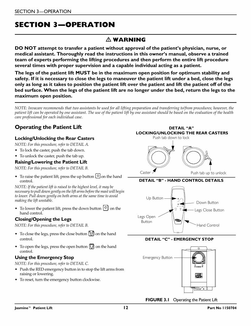
Locking/Unlocking the Rear CastersNOTE: For this procedure, refer to DETAIL A.• To lock the caster, push the tab down.• To unlock the caster, push the tab up.Raising/Lowering the Patient LiftNOTE: For this procedure, refer to DETAIL B.
• To raise the patient lift, press the up button on the hand control.
NOTE: If the patient lift is raised to the highest level, it may be necessary to pull down gently on the lift arms before the mast will begin to lower. Pull down gently on both arms at the same time to avoid making the lift unstable.
• To lower the patient lift, press the down button on the hand control.
Closing/Opening the LegsNOTE: For this procedure, refer to DETAIL B.
• To close the legs, press the close button on the hand control.
• To open the legs, press the open button on the hand control.
Using the Emergency StopNOTE: For this procedure, refer to DETAIL C.• Push the RED emergency button in to stop the lift arms from
raising or lowering.• To reset, turn the emergency button clockwise.
FIGURE 3.1 Operating the Patient Lift
Push tab down to lock
Push tab up to unlockCaster
DETAIL “A” LOCKING/UNLOCKING THE REAR CASTERS
DETAIL “B” - HAND CONTROL DETAILS
DETAIL “C” - EMERGENCY STOP
Down ButtonUp Button
Hand Control
Emergency Button
Legs Open Button
Legs Close Button
Jasmine™ Patient Lift 12 Part No 1150704
SECTION 3—OPERATION
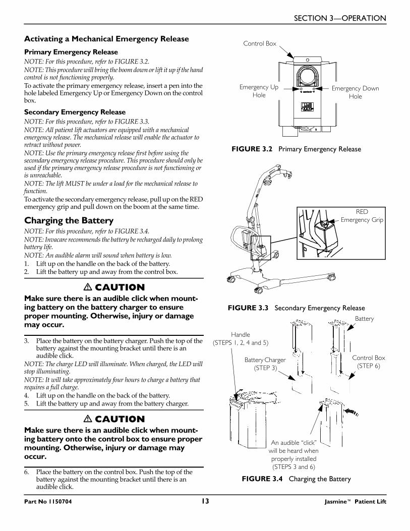
Activating a Mechanical Emergency Release
Primary Emergency ReleaseNOTE: For this procedure, refer to FIGURE 3.2.NOTE: This procedure will bring the boom down or lift it up if the hand control is not functioning properly.To activate the primary emergency release, insert a pen into the hole labeled Emergency Up or Emergency Down on the control box.
Secondary Emergency ReleaseNOTE: For this procedure, refer to FIGURE 3.3.NOTE: All patient lift actuators are equipped with a mechanical emergency release. The mechanical release will enable the actuator to retract without power.NOTE: Use the primary emergency release first before using the secondary emergency release procedure. This procedure should only be used if the primary emergency release procedure is not functioning or is unreachable.NOTE: The lift MUST be under a load for the mechanical release to function.To activate the secondary emergency release, pull up on the RED emergency grip and pull down on the boom at the same time.
Charging the BatteryNOTE: For this procedure, refer to FIGURE 3.4.NOTE: Invacare recommends the battery be recharged daily to prolong battery life. NOTE: An audible alarm will sound when battery is low.1. Lift up on the handle on the back of the battery.2. Lift the battery up and away from the control box.
� CAUTIONMake sure there is an audible click when mount-ing battery on the battery charger to ensure proper mounting. Otherwise, injury or damage may occur.
3. Place the battery on the battery charger. Push the top of the battery against the mounting bracket until there is an audible click.
NOTE: The charge LED will illuminate. When charged, the LED will stop illuminating.NOTE: It will take approximately four hours to charge a battery that requires a full charge.4. Lift up on the handle on the back of the battery.5. Lift the battery up and away from the battery charger.
� CAUTIONMake sure there is an audible click when mount-ing battery onto the control box to ensure proper mounting. Otherwise, injury or damage may occur.
6. Place the battery on the control box. Push the top of the battery against the mounting bracket until there is an audible click.
FIGURE 3.2 Primary Emergency Release
FIGURE 3.3 Secondary Emergency Release
FIGURE 3.4 Charging the Battery
Control Box
Emergency Down Hole
Emergency Up Hole
REDEmergency Grip
Battery Charger (STEP 3)
Control Box (STEP 6)
An audible “click” will be heard when properly installed(STEPS 3 and 6)
Handle(STEPS 1, 2, 4 and 5)
Battery
Part No 1150704 13 Jasmine™ Patient Lift
SECTION 4—LIFTING THE PATIENT
SECTION 4—LIFTING THE PATIENTPreparing the Lift for Use
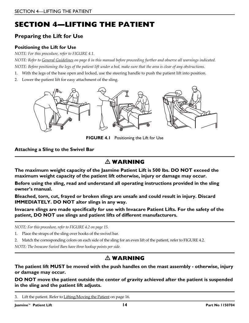
Positioning the Lift for UseNOTE: For this procedure, refer to FIGURE 4.1.NOTE: Refer to General Guidelines on page 8 in this manual before proceeding further and observe all warnings indicated.NOTE: Before positioning the legs of the patient lift under a bed, make sure that the area is clear of any obstructions. 1. With the legs of the base open and locked, use the steering handle to push the patient lift into position.2. Lower the patient lift for easy attachment of the sling.
FIGURE 4.1 Positioning the Lift for Use
Attaching a Sling to the Swivel Bar
� WARNINGThe maximum weight capacity of the Jasmine Patient Lift is 500 lbs. DO NOT exceed the maximum weight capacity of the patient lift otherwise, injury or damage may occur.Before using the sling, read and understand all operating instructions provided in the sling owner’s manual.Bleached, torn, cut, frayed or broken slings are unsafe and could result in injury. Discard IMMEDIATELY. DO NOT alter slings in any way.
Invacare slings are made specifically for use with Invacare Patient Lifts. For the safety of the patient, DO NOT use slings and patient lifts of different manufacturers.
NOTE: For this procedure, refer to FIGURE 4.2 on page 15.1. Place the straps of the sling over hooks of the swivel bar. 2. Match the corresponding colors on each side of the sling for an even lift of the patient, refer to FIGURE 4.2.NOTE: The Invacare Swivel Bars have three hookup points per side.
� WARNINGThe patient lift MUST be moved with the push handles on the mast assembly - otherwise, injury or damage may occur.DO NOT move the patient outside the center of gravity achieved after the patient is suspended in the sling and the patient lift adjusts.
3. Lift the patient. Refer to Lifting/Moving the Patient on page 16.
Jasmine™ Patient Lift 14 Part No 1150704
SECTION 4—LIFTING THE PATIENT
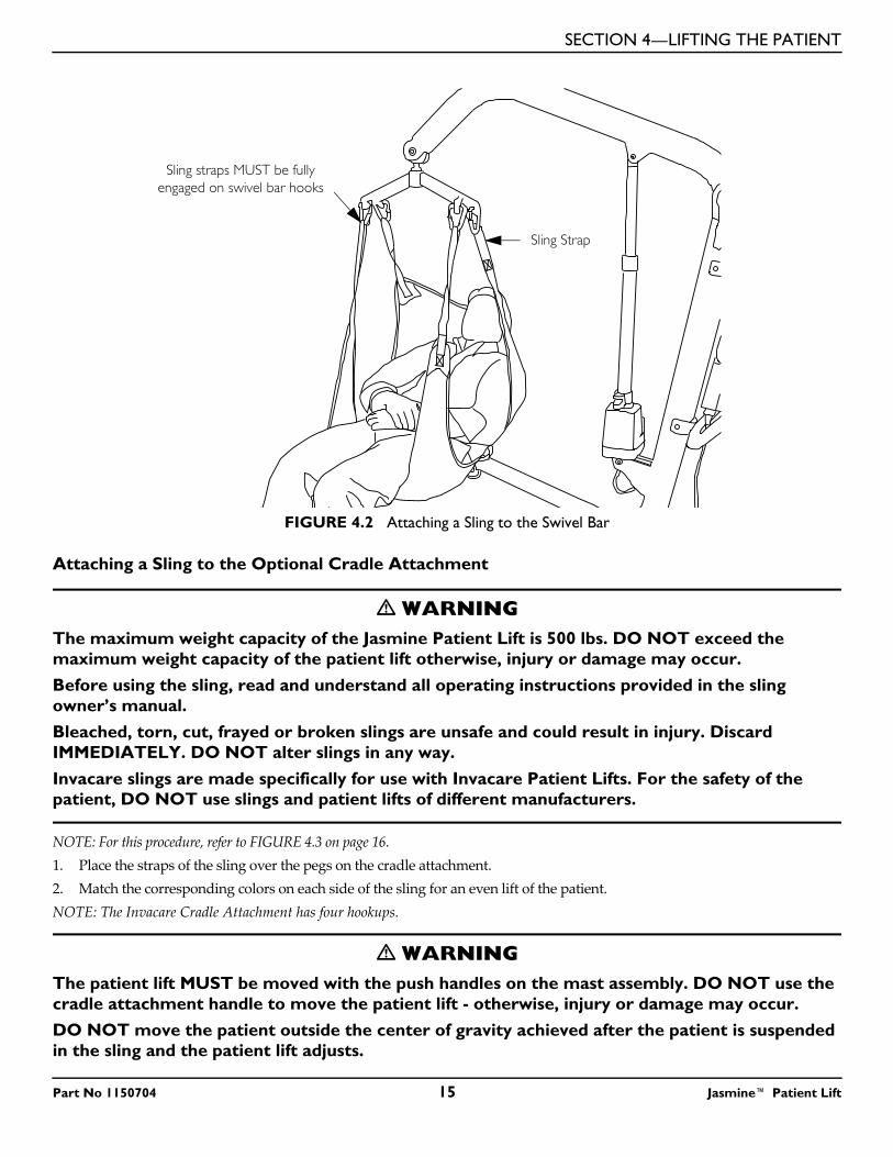
FIGURE 4.2 Attaching a Sling to the Swivel Bar
Attaching a Sling to the Optional Cradle Attachment
� WARNINGThe maximum weight capacity of the Jasmine Patient Lift is 500 lbs. DO NOT exceed the maximum weight capacity of the patient lift otherwise, injury or damage may occur.Before using the sling, read and understand all operating instructions provided in the sling owner’s manual.Bleached, torn, cut, frayed or broken slings are unsafe and could result in injury. Discard IMMEDIATELY. DO NOT alter slings in any way.Invacare slings are made specifically for use with Invacare Patient Lifts. For the safety of the patient, DO NOT use slings and patient lifts of different manufacturers.
NOTE: For this procedure, refer to FIGURE 4.3 on page 16.1. Place the straps of the sling over the pegs on the cradle attachment. 2. Match the corresponding colors on each side of the sling for an even lift of the patient.NOTE: The Invacare Cradle Attachment has four hookups.
� WARNINGThe patient lift MUST be moved with the push handles on the mast assembly. DO NOT use the cradle attachment handle to move the patient lift - otherwise, injury or damage may occur.DO NOT move the patient outside the center of gravity achieved after the patient is suspended in the sling and the patient lift adjusts.
Sling straps MUST be fully engaged on swivel bar hooks
Sling Strap
Part No 1150704 15 Jasmine™ Patient Lift
SECTION 4—LIFTING THE PATIENT
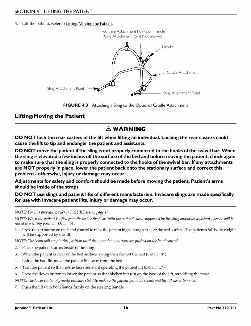
3. Lift the patient. Refer to Lifting/Moving the Patient.
FIGURE 4.3 Attaching a Sling to the Optional Cradle Attachment
Lifting/Moving the Patient
� WARNINGDO NOT lock the rear casters of the lift when lifting an individual. Locking the rear casters could cause the lift to tip and endanger the patient and assistants.DO NOT move the patient if the sling is not properly connected to the hooks of the swivel bar. When the sling is elevated a few inches off the surface of the bed and before moving the patient, check again to make sure that the sling is properly connected to the hooks of the swivel bar. If any attachments are NOT properly in place, lower the patient back onto the stationary surface and correct this problem - otherwise, injury or damage may occur.Adjustments for safety and comfort should be made before moving the patient. Patient's arms should be inside of the straps.DO NOT use slings and patient lifts of different manufacturers. Invacare slings are made specifically for use with Invacare patient lifts. Injury or damage may occur.
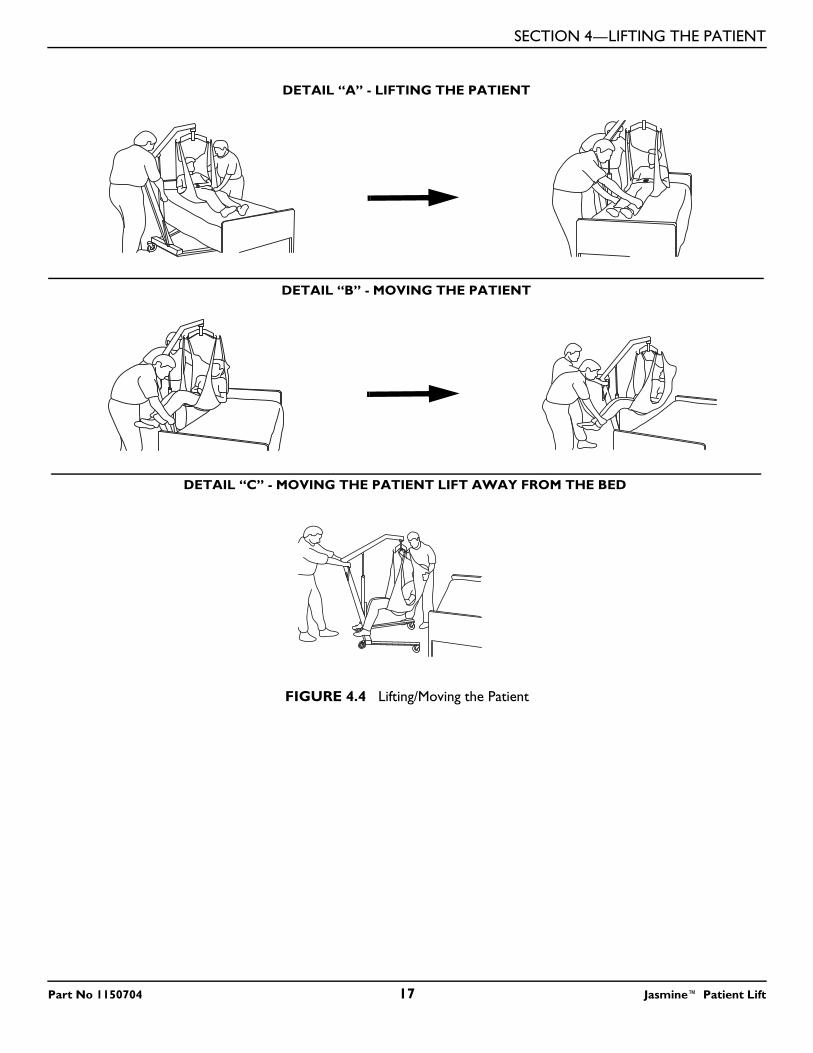
NOTE: For this procedure, refer to FIGURE 4.4 on page 17.NOTE: When the patient is lifted from the bed or the floor (with the patient’s head supported by the sling and/or an assistant), he/she will be raised to a sitting position (Detail “A ).1. Press the up button on the hand control to raise the patient high enough to clear the bed surface. The patient’s full body weight
will be supported by the lift.NOTE: The boom will stay in this position until the up or down buttons are pushed on the hand control.2. Place the patient’s arms inside of the sling.3. When the patient is clear of the bed surface, swing their feet off the bed (Detail “B”).4. Using the handle, move the patient lift away from the bed.5. Turn the patient so that he/she faces assistant operating the patient lift (Detail “C”).6. Press the down button to lower the patient so that his/her feet rest on the base of the lift, straddling the mast.NOTE: The lower center of gravity provides stability making the patient feel more secure and the lift easier to move.7. Push the lift with both hands firmly on the steering handle.
Cradle Attachment
Sling Attachment Point
Two Sling Attachment Points on Handle(One Attachment Point Not Shown)
Handle
Sling Attachment Point
Jasmine™ Patient Lift 16 Part No 1150704
SECTION 4—LIFTING THE PATIENT
FIGURE 4.4 Lifting/Moving the Patient
DETAIL “A” - LIFTING THE PATIENT
DETAIL “B” - MOVING THE PATIENT
DETAIL “C” - MOVING THE PATIENT LIFT AWAY FROM THE BED
Part No 1150704 17 Jasmine™ Patient Lift
SECTION 5—TRANSFERRING THE PATIENT
SECTION 5—TRANSFERRING THE PATIENT
� WARNINGDO NOT attempt any transfer of a patient without approval of the patient's physician, nurse, or medical assistant. DO NOT move the patient if the sling is not properly connected to the hooks of the swivel bar. When the sling is a few inches off the surface of the bed and before moving the patient, check to make sure that the sling is properly connected to the hooks of the swivel bar. If any attachments are NOT properly in place, lower the patient back onto the stationary surface and correct this problem - otherwise, injury or damage may occur.Adjustments for safety and comfort should be made before moving the patient. The patient's arms should be inside the straps.DO NOT use slings and patient lifts of different manufacturers. Invacare slings are made specifically for use with Invacare patient lifts. Otherwise, injury or damage may occur.DO NOT lock the rear casters of the patient lift when lifting an individual. Locking the rear casters could cause the patient lift to tip and endanger the patient and assistants.The legs of the patient lift MUST be in the maximum open position for optimum stability and safety. If it is necessary to close the legs to maneuver the patient lift under a bed, close the legs only as long as it takes to position the patient lift over the patient and lift the patient off the surface of the bed. When the legs of the patient lift are no longer under the bed, return the legs to the maximum open position.Be sure to check the sling attachments each time the sling is removed and replaced to ensure that it is properly attached before the patient is removed from a bed or chair.
NOTE: The slings with commode openings are designed to be used with either a commode chair or standard commode. Invacare recommends that the sling remain connected to the swivel bar hooks during the patient’s use of either the commode chair or standard commode.NOTE: Invacare recommends that two assistants be used for all lifting preparation and transferring to/from procedures; however, our equipment will permit proper operation by one assistant. The use of one assistant is based on the evaluation of the health care professional for each individual case.
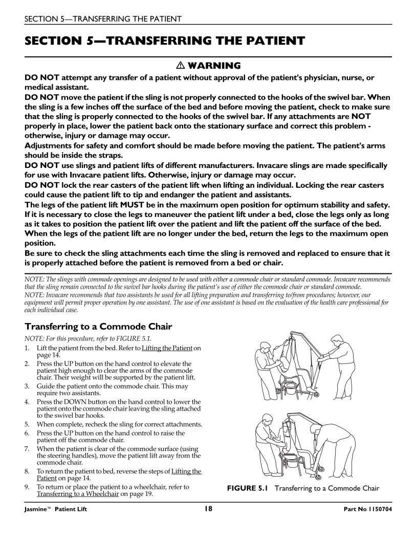
Transferring to a Commode ChairNOTE: For this procedure, refer to FIGURE 5.1.1. Lift the patient from the bed. Refer to Lifting the Patient on
page 14.2. Press the UP button on the hand control to elevate the
patient high enough to clear the arms of the commode chair. Their weight will be supported by the patient lift.
3. Guide the patient onto the commode chair. This may require two assistants.
4. Press the DOWN button on the hand control to lower the patient onto the commode chair leaving the sling attached to the swivel bar hooks.
5. When complete, recheck the sling for correct attachments.6. Press the UP button on the hand control to raise the
patient off the commode chair.7. When the patient is clear of the commode surface (using
the steering handles), move the patient lift away from the commode chair.
8. To return the patient to bed, reverse the steps of Lifting the Patient on page 14.
9. To return or place the patient to a wheelchair, refer to Transferring to a Wheelchair on page 19.
FIGURE 5.1 Transferring to a Commode Chair
Jasmine™ Patient Lift 18 Part No 1150704
SECTION 5—TRANSFERRING THE PATIENT
Transferring to a Standard CommodeNOTE: The Invacare patient lift is NOT a transport device. If the bathroom facilities are not near the bed or if the patient lift cannot be easily maneuvered towards the commode, then the patient MUST be transferred to a wheelchair and transported to the bathroom facilities before using the patient lift again to position the patient on a standard commode. Refer to Transferring to a Wheelchair on page 19.1. Use an empty patient lift to check if the patient lift can maneuver around the commode.2. If the patient lift can maneuver around the commode, lift the patient from the bed. Refer to Lifting the Patient on page 14.3. Move the patient to the commode.4. Press the UP/DOWN buttons on the hand control to elevate the patient high enough to clear the commode. Their weight will
be supported by the patient lift.5. Guide the patient onto the commode. This may require two assistants.6. Press the DOWN button on the hand control to lower the patient onto the standard commode leaving the sling attached to
the swivel bar hooks.7. When complete, recheck the sling for correct attachments.8. Press the UP button on the hand control to raise the patient off the commode.9. When patient is clear of the commode surface (using the steering handle), move the lift away from the commode.10. To return the patient to bed, reverse the steps of Lifting the Patient on page 14.11. To return or place patient to a wheelchair, refer to Transferring to a Wheelchair.
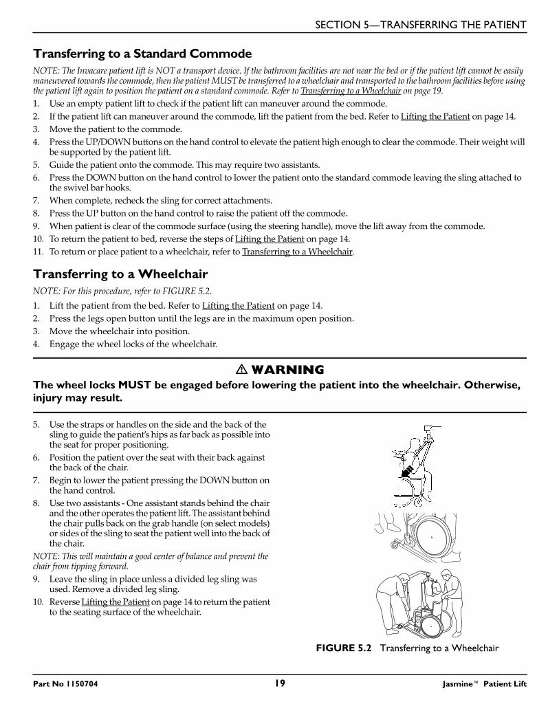
Transferring to a WheelchairNOTE: For this procedure, refer to FIGURE 5.2.1. Lift the patient from the bed. Refer to Lifting the Patient on page 14.2. Press the legs open button until the legs are in the maximum open position.3. Move the wheelchair into position.4. Engage the wheel locks of the wheelchair.
� WARNINGThe wheel locks MUST be engaged before lowering the patient into the wheelchair. Otherwise, injury may result.
5. Use the straps or handles on the side and the back of the sling to guide the patient’s hips as far back as possible into the seat for proper positioning.
6. Position the patient over the seat with their back against the back of the chair.
7. Begin to lower the patient pressing the DOWN button on the hand control.
8. Use two assistants - One assistant stands behind the chair and the other operates the patient lift. The assistant behind the chair pulls back on the grab handle (on select models) or sides of the sling to seat the patient well into the back of the chair.
NOTE: This will maintain a good center of balance and prevent the chair from tipping forward.9. Leave the sling in place unless a divided leg sling was
used. Remove a divided leg sling.10. Reverse Lifting the Patient on page 14 to return the patient
to the seating surface of the wheelchair.
FIGURE 5.2 Transferring to a Wheelchair
Part No 1150704 19 Jasmine™ Patient Lift
SECTION 6—TROUBLESHOOTING
Jasmine™ Patient Lift 20 Part No 1150704
SECTION 6—TROUBLESHOOTING
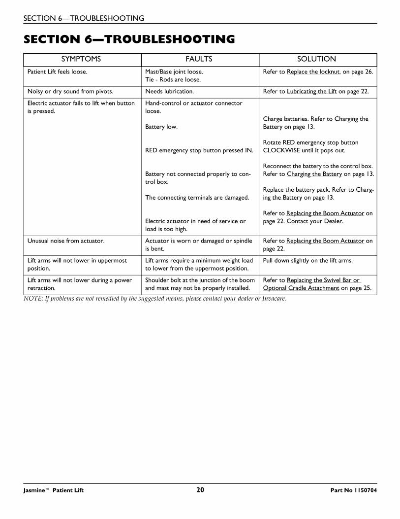
NOTE: If problems are not remedied by the suggested means, please contact your dealer or Invacare.
SYMPTOMS FAULTS SOLUTION
Patient Lift feels loose. Mast/Base joint loose.Tie - Rods are loose.
Refer to Replace the locknut. on page 26.
Noisy or dry sound from pivots. Needs lubrication. Refer to Lubricating the Lift on page 22.
Electric actuator fails to lift when button is pressed.
Hand-control or actuator connector loose.
Battery low.
RED emergency stop button pressed IN.
Battery not connected properly to con-trol box.
The connecting terminals are damaged.
Electric actuator in need of service or load is too high.
Charge batteries. Refer to Charging the Battery on page 13.
Rotate RED emergency stop button CLOCKWISE until it pops out.
Reconnect the battery to the control box. Refer to Charging the Battery on page 13.
Replace the battery pack. Refer to Charg-ing the Battery on page 13.
Refer to Replacing the Boom Actuator on page 22. Contact your Dealer.
Unusual noise from actuator. Actuator is worn or damaged or spindle is bent.
Refer to Replacing the Boom Actuator on page 22.
Lift arms will not lower in uppermost position.
Lift arms require a minimum weight load to lower from the uppermost position.
Pull down slightly on the lift arms.
Lift arms will not lower during a power retraction.
Shoulder bolt at the junction of the boom and mast may not be properly installed.
Refer to Replacing the Swivel Bar or Optional Cradle Attachment on page 25.
SECTION 7—MAINTENANCE
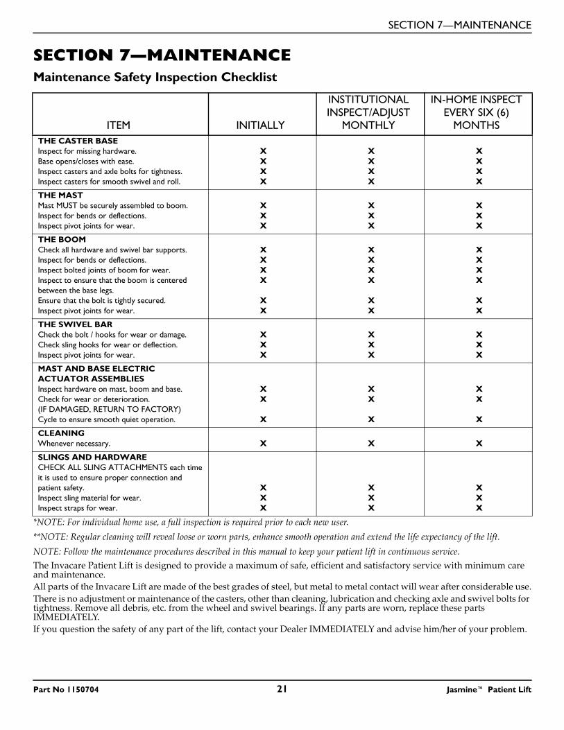
SECTION 7—MAINTENANCEMaintenance Safety Inspection Checklist
*NOTE: For individual home use, a full inspection is required prior to each new user.**NOTE: Regular cleaning will reveal loose or worn parts, enhance smooth operation and extend the life expectancy of the lift.NOTE: Follow the maintenance procedures described in this manual to keep your patient lift in continuous service.The Invacare Patient Lift is designed to provide a maximum of safe, efficient and satisfactory service with minimum care and maintenance.All parts of the Invacare Lift are made of the best grades of steel, but metal to metal contact will wear after considerable use.There is no adjustment or maintenance of the casters, other than cleaning, lubrication and checking axle and swivel bolts for tightness. Remove all debris, etc. from the wheel and swivel bearings. If any parts are worn, replace these parts IMMEDIATELY. If you question the safety of any part of the lift, contact your Dealer IMMEDIATELY and advise him/her of your problem.
ITEM INITIALLY
INSTITUTIONAL INSPECT/ADJUST
MONTHLY
IN-HOME INSPECT EVERY SIX (6)
MONTHSTHE CASTER BASEInspect for missing hardware.Base opens/closes with ease.Inspect casters and axle bolts for tightness.Inspect casters for smooth swivel and roll.
XXXX
XXXX
XXXX
THE MASTMast MUST be securely assembled to boom.Inspect for bends or deflections.Inspect pivot joints for wear.
XXX
XXX
XXX
THE BOOMCheck all hardware and swivel bar supports.Inspect for bends or deflections.Inspect bolted joints of boom for wear.Inspect to ensure that the boom is centered between the base legs.Ensure that the bolt is tightly secured.Inspect pivot joints for wear.
XXXX
XX
XXXX
XX
XXXX
XX
THE SWIVEL BAR Check the bolt / hooks for wear or damage.Check sling hooks for wear or deflection.Inspect pivot joints for wear.
XXX
XXX
XXX
MAST AND BASE ELECTRIC ACTUATOR ASSEMBLIESInspect hardware on mast, boom and base.Check for wear or deterioration.(IF DAMAGED, RETURN TO FACTORY)Cycle to ensure smooth quiet operation.
XX
X
XX
X
XX
X
CLEANINGWhenever necessary. X X X
SLINGS AND HARDWARECHECK ALL SLING ATTACHMENTS each time it is used to ensure proper connection and patient safety.Inspect sling material for wear.Inspect straps for wear.
XXX
XXX
XXX
Part No 1150704 21 Jasmine™ Patient Lift
SECTION 7—MAINTENANCE
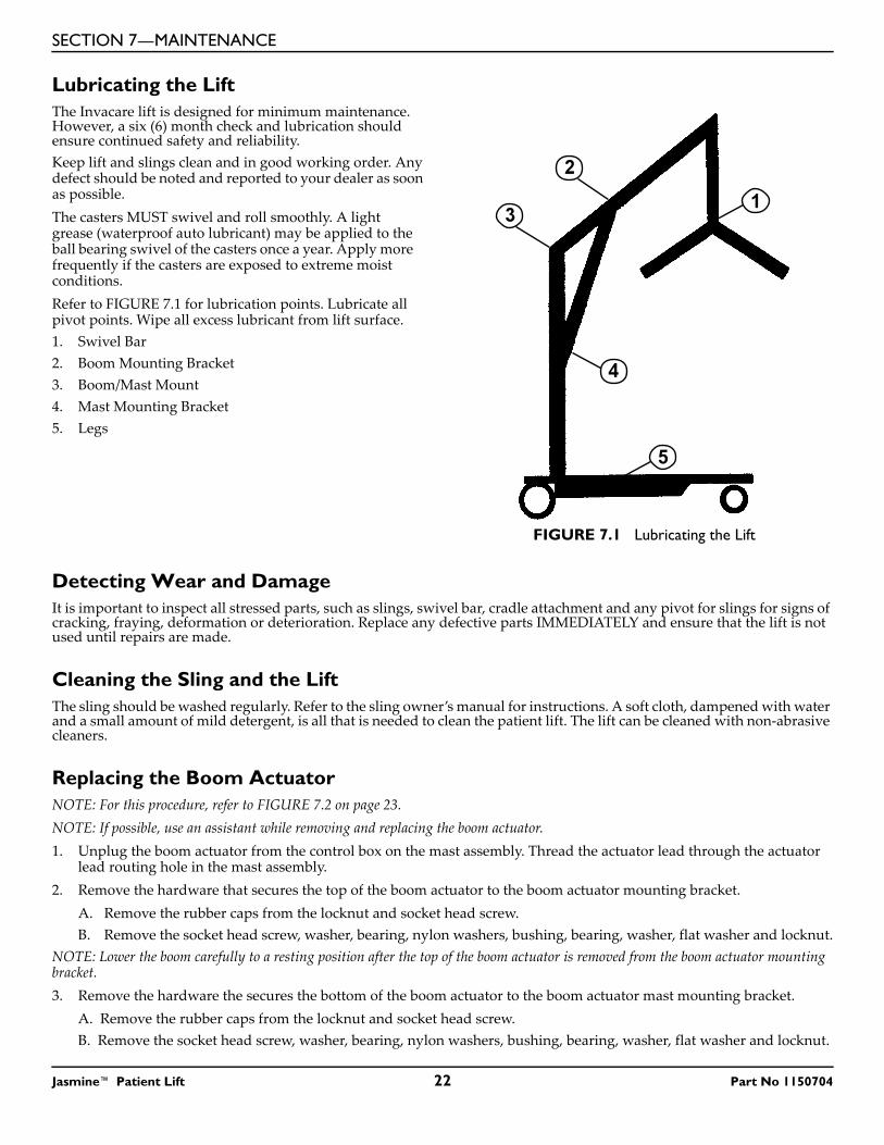
Lubricating the LiftThe Invacare lift is designed for minimum maintenance. However, a six (6) month check and lubrication should ensure continued safety and reliability.Keep lift and slings clean and in good working order. Any defect should be noted and reported to your dealer as soon as possible.The casters MUST swivel and roll smoothly. A light grease (waterproof auto lubricant) may be applied to the ball bearing swivel of the casters once a year. Apply more frequently if the casters are exposed to extreme moist conditions.Refer to FIGURE 7.1 for lubrication points. Lubricate all pivot points. Wipe all excess lubricant from lift surface.1. Swivel Bar2. Boom Mounting Bracket3. Boom/Mast Mount4. Mast Mounting Bracket5. Legs
FIGURE 7.1 Lubricating the Lift
Detecting Wear and DamageIt is important to inspect all stressed parts, such as slings, swivel bar, cradle attachment and any pivot for slings for signs of cracking, fraying, deformation or deterioration. Replace any defective parts IMMEDIATELY and ensure that the lift is not used until repairs are made.
Cleaning the Sling and the LiftThe sling should be washed regularly. Refer to the sling owner’s manual for instructions. A soft cloth, dampened with water and a small amount of mild detergent, is all that is needed to clean the patient lift. The lift can be cleaned with non-abrasive cleaners.
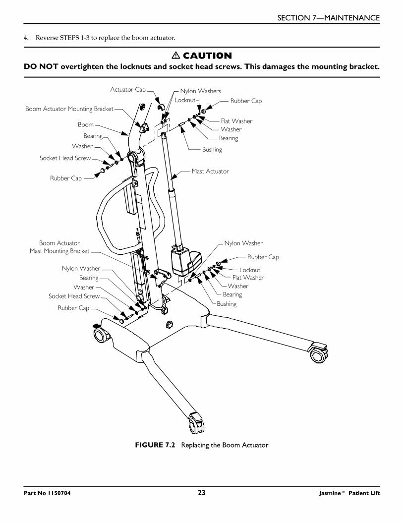
Replacing the Boom ActuatorNOTE: For this procedure, refer to FIGURE 7.2 on page 23.NOTE: If possible, use an assistant while removing and replacing the boom actuator.1. Unplug the boom actuator from the control box on the mast assembly. Thread the actuator lead through the actuator
lead routing hole in the mast assembly.2. Remove the hardware that secures the top of the boom actuator to the boom actuator mounting bracket.
A. Remove the rubber caps from the locknut and socket head screw.B. Remove the socket head screw, washer, bearing, nylon washers, bushing, bearing, washer, flat washer and locknut.
NOTE: Lower the boom carefully to a resting position after the top of the boom actuator is removed from the boom actuator mounting bracket.3. Remove the hardware the secures the bottom of the boom actuator to the boom actuator mast mounting bracket.
A. Remove the rubber caps from the locknut and socket head screw.B. Remove the socket head screw, washer, bearing, nylon washers, bushing, bearing, washer, flat washer and locknut.
5
Jasmine™ Patient Lift 22 Part No 1150704
SECTION 7—MAINTENANCE
4. Reverse STEPS 1-3 to replace the boom actuator.
� CAUTIONDO NOT overtighten the locknuts and socket head screws. This damages the mounting bracket.
FIGURE 7.2 Replacing the Boom Actuator
Boom
Rubber Cap
Mast Actuator
Socket Head ScrewBushing
Washer
Flat WasherLocknut
Rubber Cap
Bearing
Locknut Rubber Cap
Flat Washer
Bearing
Washer
Rubber Cap
Socket Head Screw
Bearing
Bushing
Boom Actuator Mounting Bracket
Boom Actuator Mast Mounting Bracket
Washer
Washer
Nylon WashersActuator Cap
Nylon Washer
BearingNylon Washer
Part No 1150704 23 Jasmine™ Patient Lift
SECTION 7—MAINTENANCE
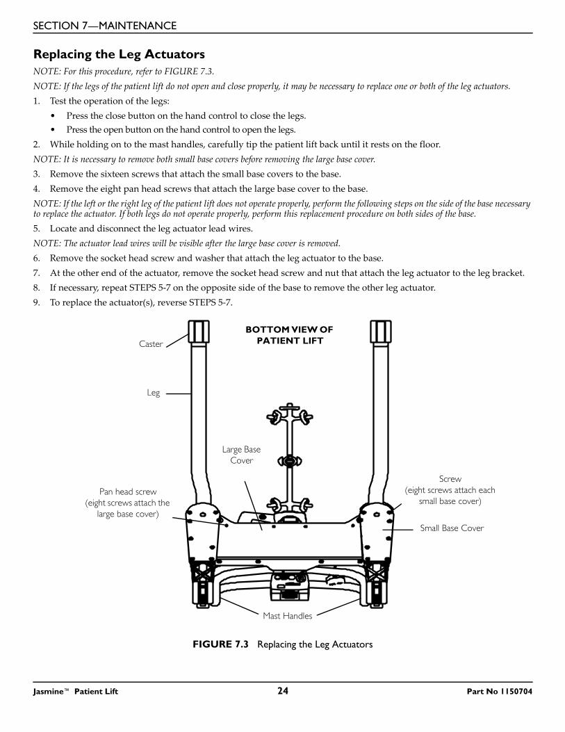
Replacing the Leg ActuatorsNOTE: For this procedure, refer to FIGURE 7.3.NOTE: If the legs of the patient lift do not open and close properly, it may be necessary to replace one or both of the leg actuators. 1. Test the operation of the legs:
• Press the close button on the hand control to close the legs.• Press the open button on the hand control to open the legs.
2. While holding on to the mast handles, carefully tip the patient lift back until it rests on the floor.NOTE: It is necessary to remove both small base covers before removing the large base cover.3. Remove the sixteen screws that attach the small base covers to the base.4. Remove the eight pan head screws that attach the large base cover to the base.NOTE: If the left or the right leg of the patient lift does not operate properly, perform the following steps on the side of the base necessary to replace the actuator. If both legs do not operate properly, perform this replacement procedure on both sides of the base.5. Locate and disconnect the leg actuator lead wires. NOTE: The actuator lead wires will be visible after the large base cover is removed.6. Remove the socket head screw and washer that attach the leg actuator to the base.7. At the other end of the actuator, remove the socket head screw and nut that attach the leg actuator to the leg bracket.8. If necessary, repeat STEPS 5-7 on the opposite side of the base to remove the other leg actuator.9. To replace the actuator(s), reverse STEPS 5-7.
FIGURE 7.3 Replacing the Leg Actuators
Small Base Cover
Mast Handles
BOTTOM VIEW OF PATIENT LIFT
Large Base Cover
Screw (eight screws attach each
small base cover)Pan head screw
(eight screws attach the large base cover)
Leg
Caster
Jasmine™ Patient Lift 24 Part No 1150704
SECTION 7—MAINTENANCE
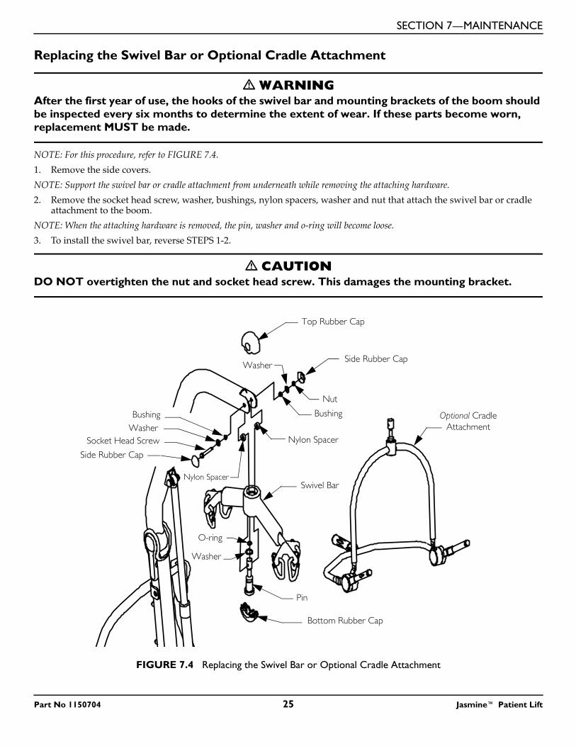
Replacing the Swivel Bar or Optional Cradle Attachment
� WARNINGAfter the first year of use, the hooks of the swivel bar and mounting brackets of the boom should be inspected every six months to determine the extent of wear. If these parts become worn, replacement MUST be made.
NOTE: For this procedure, refer to FIGURE 7.4.1. Remove the side covers.NOTE: Support the swivel bar or cradle attachment from underneath while removing the attaching hardware.2. Remove the socket head screw, washer, bushings, nylon spacers, washer and nut that attach the swivel bar or cradle
attachment to the boom.NOTE: When the attaching hardware is removed, the pin, washer and o-ring will become loose.3. To install the swivel bar, reverse STEPS 1-2.
� CAUTIONDO NOT overtighten the nut and socket head screw. This damages the mounting bracket.
FIGURE 7.4 Replacing the Swivel Bar or Optional Cradle Attachment
Top Rubber Cap
Side Rubber Cap
Nut
Washer
Nylon Spacer
Nylon Spacer
Side Rubber Cap
Socket Head ScrewWasherBushing
Swivel Bar
Bottom Rubber Cap
Pin
O-ring
Washer
Optional Cradle Attachment
Bushing
Part No 1150704 25 Jasmine™ Patient Lift
SECTION 7—MAINTENANCE
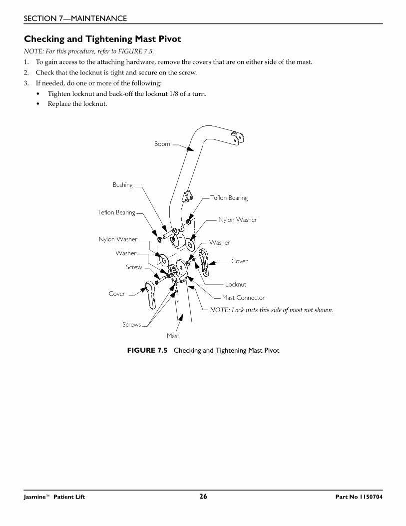
Checking and Tightening Mast PivotNOTE: For this procedure, refer to FIGURE 7.5.1. To gain access to the attaching hardware, remove the covers that are on either side of the mast.2. Check that the locknut is tight and secure on the screw.3. If needed, do one or more of the following:
• Tighten locknut and back-off the locknut 1/8 of a turn.• Replace the locknut.
FIGURE 7.5 Checking and Tightening Mast Pivot
Boom
Washer
Cover
Mast Connector
Locknut
Bushing
Washer
Screw
Cover
NOTE: Lock nuts this side of mast not shown.
Mast
Screws
Nylon WasherTeflon Bearing
Teflon Bearing
Nylon Washer
Jasmine™ Patient Lift 26 Part No 1150704
SECTION 8—ACCESSORIES
SECTION 8—ACCESSORIES
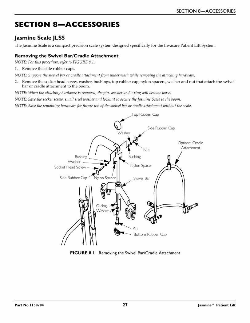
Jasmine Scale JLS5The Jasmine Scale is a compact precision scale system designed specifically for the Invacare Patient Lift System.
Removing the Swivel Bar/Cradle AttachmentNOTE: For this procedure, refer to FIGURE 8.1.1. Remove the side rubber caps.NOTE: Support the swivel bar or cradle attachment from underneath while removing the attaching hardware.2. Remove the socket head screw, washer, bushings, top rubber cap, nylon spacers, washer and nut that attach the swivel
bar or cradle attachment to the boom.NOTE: When the attaching hardware is removed, the pin, washer and o-ring will become loose.NOTE: Save the socket screw, small steel washer and locknut to secure the Jasmine Scale to the boom.NOTE: Save the remaining hardware for future use of the swivel bar or cradle attachment without the scale.
FIGURE 8.1 Removing the Swivel Bar/Cradle Attachment
Top Rubber Cap
Side Rubber Cap
Nut
Washer
Nylon Spacer
Nylon SpacerSide Rubber Cap
Socket Head ScrewWasher
Bushing
Swivel Bar
Bottom Rubber Cap
Pin
O-ringWasher
Optional Cradle Attachment
Bushing
Part No 1150704 27 Jasmine™ Patient Lift
SECTION 8—ACCESSORIES
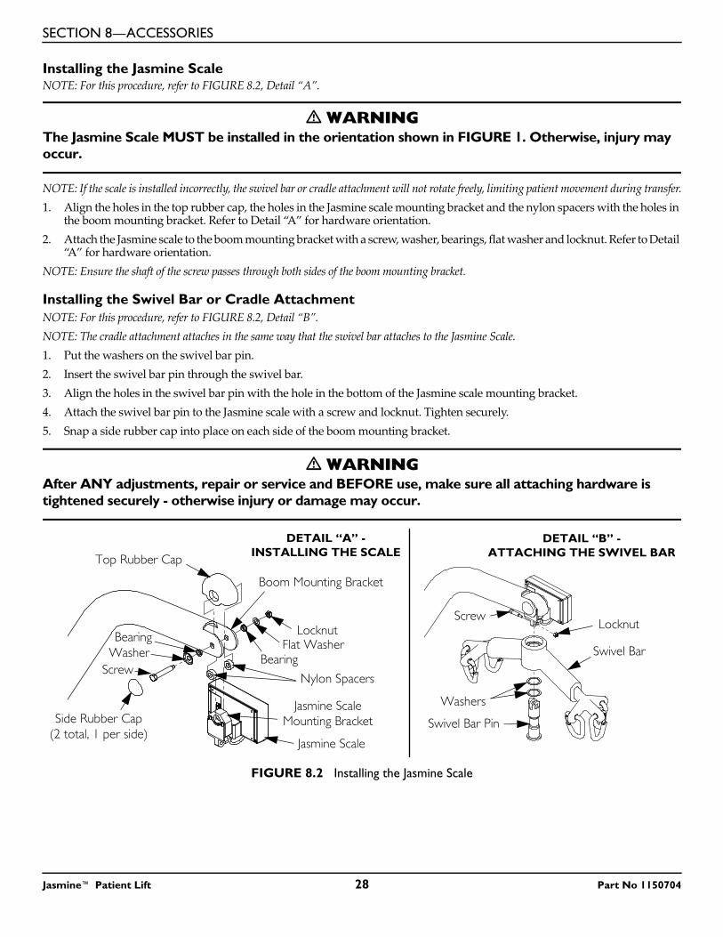
Installing the Jasmine ScaleNOTE: For this procedure, refer to FIGURE 8.2, Detail “A”.
� WARNINGThe Jasmine Scale MUST be installed in the orientation shown in FIGURE 1. Otherwise, injury may occur.
NOTE: If the scale is installed incorrectly, the swivel bar or cradle attachment will not rotate freely, limiting patient movement during transfer.1. Align the holes in the top rubber cap, the holes in the Jasmine scale mounting bracket and the nylon spacers with the holes in
the boom mounting bracket. Refer to Detail “A” for hardware orientation.2. Attach the Jasmine scale to the boom mounting bracket with a screw, washer, bearings, flat washer and locknut. Refer to Detail
“A” for hardware orientation.NOTE: Ensure the shaft of the screw passes through both sides of the boom mounting bracket.
Installing the Swivel Bar or Cradle AttachmentNOTE: For this procedure, refer to FIGURE 8.2, Detail “B”.NOTE: The cradle attachment attaches in the same way that the swivel bar attaches to the Jasmine Scale.1. Put the washers on the swivel bar pin. 2. Insert the swivel bar pin through the swivel bar.3. Align the holes in the swivel bar pin with the hole in the bottom of the Jasmine scale mounting bracket.4. Attach the swivel bar pin to the Jasmine scale with a screw and locknut. Tighten securely.5. Snap a side rubber cap into place on each side of the boom mounting bracket.
� WARNINGAfter ANY adjustments, repair or service and BEFORE use, make sure all attaching hardware is tightened securely - otherwise injury or damage may occur.
FIGURE 8.2 Installing the Jasmine Scale
Locknut
Swivel Bar
Washers
Swivel Bar Pin
Jasmine Scale
Locknut
Nylon Spacers
Flat Washer
Top Rubber Cap
Bearing
Side Rubber Cap(2 total, 1 per side)
Boom Mounting Bracket
Screw
BearingWasher
Screw
DETAIL “B” -ATTACHING THE SWIVEL BAR
DETAIL “A” - INSTALLING THE SCALE
Jasmine Scale Mounting Bracket
Jasmine™ Patient Lift 28 Part No 1150704
SECTION 8—ACCESSORIES
Operating the Scale
Keypad Functions
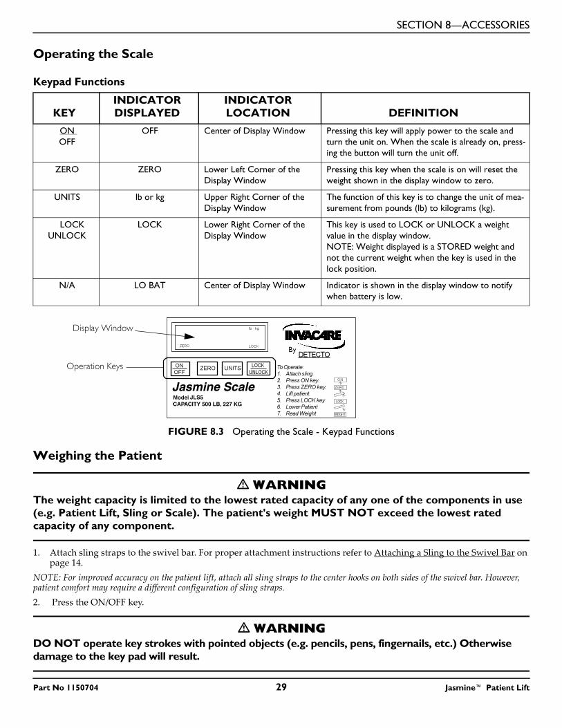
FIGURE 8.3 Operating the Scale - Keypad Functions
Weighing the Patient
� WARNINGThe weight capacity is limited to the lowest rated capacity of any one of the components in use (e.g. Patient Lift, Sling or Scale). The patient's weight MUST NOT exceed the lowest rated capacity of any component.
1. Attach sling straps to the swivel bar. For proper attachment instructions refer to Attaching a Sling to the Swivel Bar on page 14.
NOTE: For improved accuracy on the patient lift, attach all sling straps to the center hooks on both sides of the swivel bar. However, patient comfort may require a different configuration of sling straps.2. Press the ON/OFF key.
� WARNINGDO NOT operate key strokes with pointed objects (e.g. pencils, pens, fingernails, etc.) Otherwise damage to the key pad will result.
KEYINDICATORDISPLAYED
INDICATORLOCATION DEFINITION
ON OFF
OFF Center of Display Window Pressing this key will apply power to the scale and turn the unit on. When the scale is already on, press-ing the button will turn the unit off.
ZERO ZERO Lower Left Corner of the Display Window
Pressing this key when the scale is on will reset the weight shown in the display window to zero.
UNITS lb or kg Upper Right Corner of the Display Window
The function of this key is to change the unit of mea-surement from pounds (lb) to kilograms (kg).
LOCK UNLOCK
LOCK Lower Right Corner of the Display Window
This key is used to LOCK or UNLOCK a weight value in the display window.NOTE: Weight displayed is a STORED weight and not the current weight when the key is used in the lock position.
N/A LO BAT Center of Display Window Indicator is shown in the display window to notify when battery is low.
Jasmine ScaleJLS5
CAPACITY 500 LB, 227 KG
Operation Keys
Display Window
Part No 1150704 29 Jasmine™ Patient Lift
SECTION 8—ACCESSORIES
NOTE: The display will indicate the last weight that was measured. The word "LOCK" will be seen in the display box.NOTE: The ZERO key is pressed in order to avoid capturing the weight of the sling and the hardware. If the ZERO key is not pressed the weight of the sling and the weight of the hardware will be included in the weight displayed. NOT ZERO-ING OUT WILL GIVE A FALSE READING OF THE USER'S TRUE WEIGHT.3. Press the ZERO key. When the ZERO key is pushed the following will happen:
A. The scale will reset to zero and the word "ZERO" will appear in the display.B. The lock function will then be turned off and the word "LOCK" will disappear from the display.
NOTE: The scale is now active and continually updating the weight display.4. Place the patient in the sling. For patient placement instructions refer to Operation on page 12.5. Activate the lift mechanism to raise the patient until they are completely supported by the lift. For patient lifting instructions,
refer to Lifting the Patient on page 14.6. Note the weight display.7. When the weight display becomes stable press the LOCK button to lock the weight display. This will be indicated by the word
"LOCK" appearing in the display window. NOTE: Should it be necessary to unlock the weight while the patient is still supported by the lift, the UNLOCK button may be pressed. The weight will unlock and the word "LOCK" will disappear from the display window. The weight value will then be updated. Once the weight becomes stable the weight can be locked again by pressing the LOCK button.NOTE: Stable being defined as the weight fluctuating two tenths (2/10) of a pound. For example, a patient weighing one hundred (100) lbs the scale will fluctuate between 99.8 and 100.2 until the LOCK key is pressed. Fluctuation of the weight displayed is normal as noted above. Press the LOCK button to lock the weight.NOTE: The UNITS button can be pressed to toggle between units of pounds and kilograms. This is indicated by lb or kg appearing in the display window.8. The lift may now be lowered and the sling removed from the patient.NOTE: The patient's weight will continue to be seen in the display window. The display will turn off automatically after a two minute period of non-use [no changes in weight exceeding five (5) pounds (2 kilograms)]. You can NOT adjust the time delay for automatic shut off. After the display has turned off, the weight may be recalled by pressing the ON/OFF button. The unit can be turned off by pressing the ON/OFF button a second time.
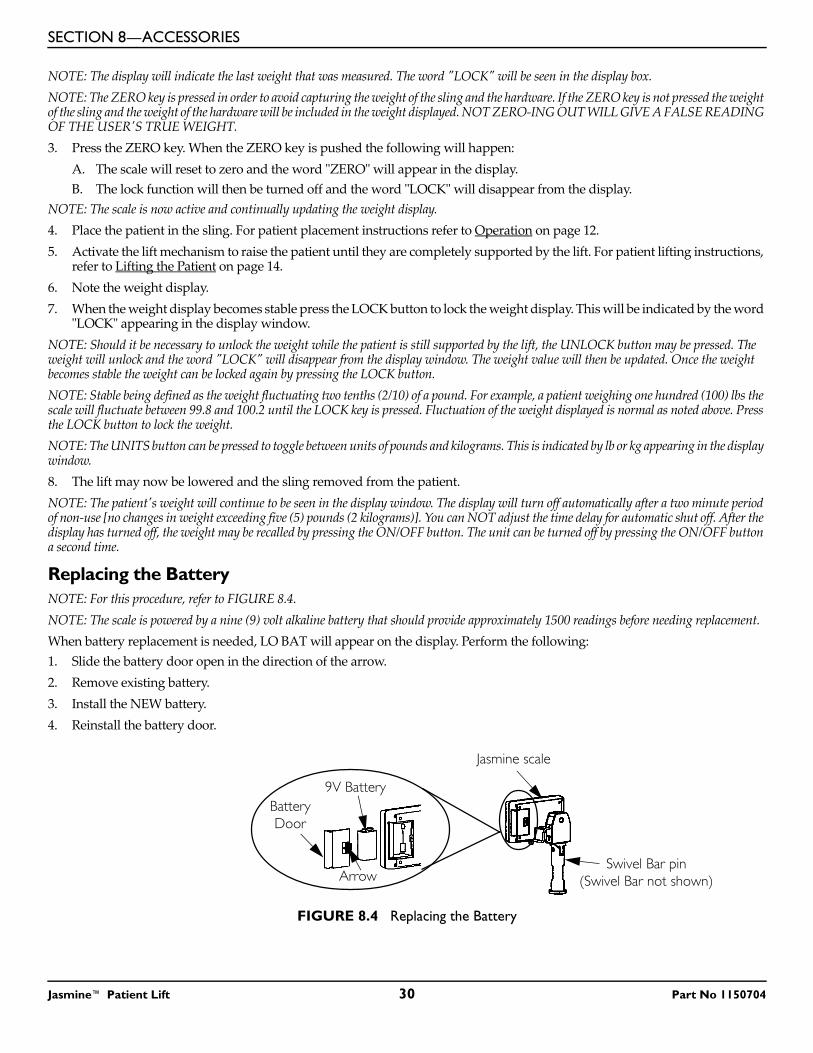
Replacing the BatteryNOTE: For this procedure, refer to FIGURE 8.4.NOTE: The scale is powered by a nine (9) volt alkaline battery that should provide approximately 1500 readings before needing replacement.When battery replacement is needed, LO BAT will appear on the display. Perform the following:1. Slide the battery door open in the direction of the arrow.2. Remove existing battery.3. Install the NEW battery.4. Reinstall the battery door.
FIGURE 8.4 Replacing the Battery
Battery Door
9V Battery
Jasmine scale
ArrowSwivel Bar pin
(Swivel Bar not shown)
Jasmine™ Patient Lift 30 Part No 1150704
SECTION 8—ACCESSORIES
Calibrating the Jasmine ScaleNOTE: The Jasmine Scale will be pre-calibrated at the factory with the load cell. Should it be necessary to re-calibrate the scale, follow the instructions outlined below.1. The patient and the sling MUST be removed from the scale to properly calibrate the Jasmine Scale. For removing the
patient instructions refer to Operation on page 12. For sling detachment instructions refer to Lifting the Patient on page 14.
2. With the Jasmine Scale on, remove the four screws on the back of the enclosure and remove the front cover to expose the PC board.
3. Press the CAL button located on the PC board. The CAL switch is not labeled but is the only button on the PC board located in the lower right corner. Once the CAL button is pushed "CAL1" will be seen in the display window.
NOTE: CAL1 selects the calibration mode using 50 pounds of calibrated weight. CAL2 selects the calibration mode for use with 200 pounds of calibrated weight. Pressing the UNITS key toggles between CAL1 and CAL2.4. When the desired calibration mode is displayed, press the LOCK/UNLOCK key. NOTE: The display window will now show UnLd.5. Ensure that there is no load on the scale and press the ZERO key.6. The display window will show a dashed line (------) scrolling across and then the word LOAD will appear in the display
window.7. Perform one (1) of the following:
A. FOR CAL1 OPTION - support 50 pounds of calibrated weight from the scale and press the ZERO key.B. FOR CAL2 OPTION - support 200 pounds of calibrated weight from the scale and press the ZERO key.
8. The display window will show a dashed line (------) scrolling across and then the word DONE will appear in the display window.
9. Remove the weight from the scale and press the LOCK/UNLOCK key.NOTE: The unit will now be in a temporary test mode and will not lock the weight display. This will allow weight to be loaded and unloaded to check the calibration. 10. Turn the unit off by pressing the ON/OFF key. 11. Turn the unit on by pressing the ON/OFF key.NOTE: Scale will now be in normal operation.
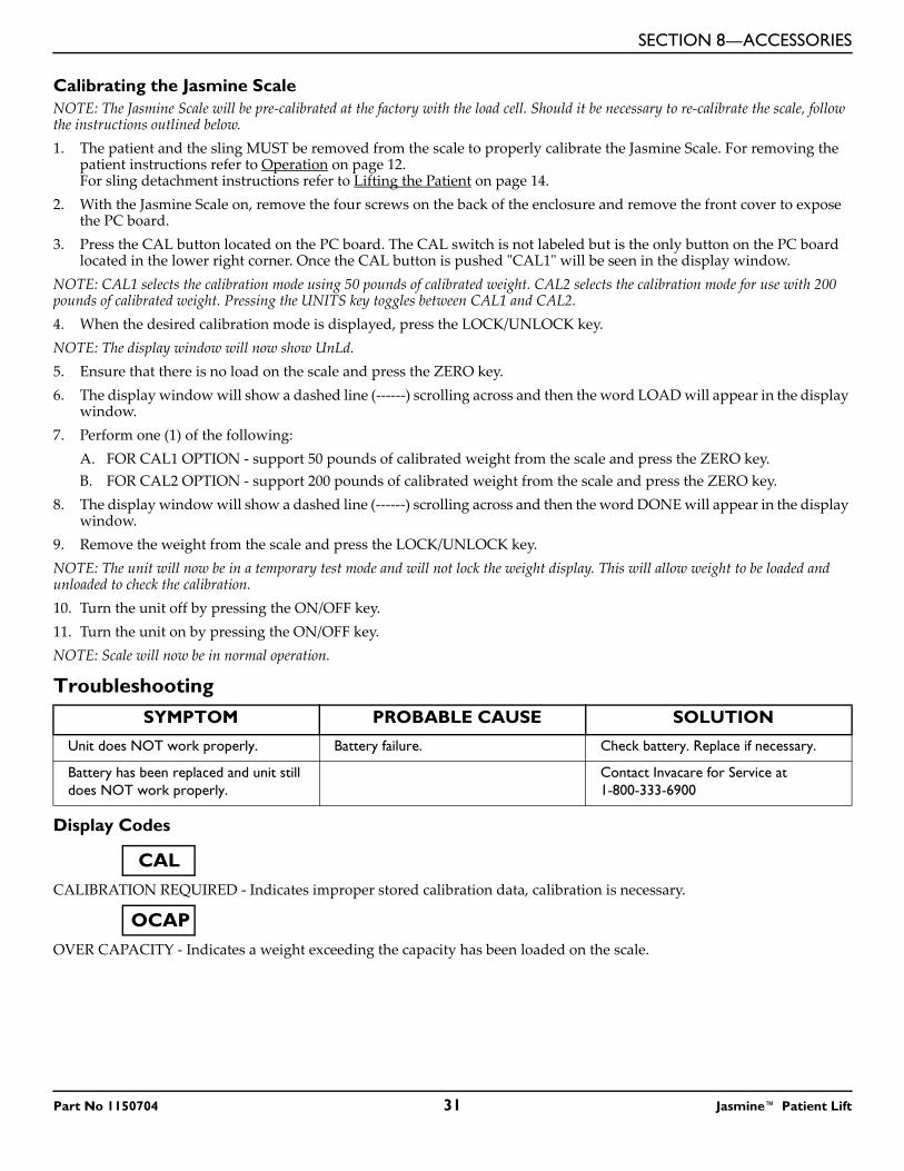
Troubleshooting
Display Codes
CALIBRATION REQUIRED - Indicates improper stored calibration data, calibration is necessary.
OVER CAPACITY - Indicates a weight exceeding the capacity has been loaded on the scale.
SYMPTOM PROBABLE CAUSE SOLUTION
Unit does NOT work properly. Battery failure. Check battery. Replace if necessary.
Battery has been replaced and unit still does NOT work properly.
Contact Invacare for Service at 1-800-333-6900
CAL
OCAP
Part No 1150704 31 Jasmine™ Patient Lift

SECTION 8—ACCESSORIES
NOTES
Jasmine™ Patient Lift 32 Part No 1150704

SECTION 8—ACCESSORIES
NOTES
Part No 1150704 33 Jasmine™ Patient Lift
LIMITED WARRANTY
Jasmine™ Patient Lift 34 Part No 1150704
LIMITED WARRANTYPLEASE NOTE: THE WARRANTY BELOW HAS BEEN DRAFTED TO COMPLY WITH FEDERAL LAW APPLICABLE TO PRODUCTS MANUFACTURED AFTER JULY 4, 1975.This warranty is extended only to the original purchaser/user of our products.This warranty gives you specific legal rights and you may also have other legal rights which vary from state to state.Invacare warrants the products manufactured to be free from defects in materials and workmanship for a period of five years on the lift and two years on the electric components from the date of purchase. If within such warranty period any such product shall be proven to be defective, such product shall be repaired or replaced, at Invacare’s option, with refurbished or new parts. This warranty does not include any labor or shipping charges incurred in replacement part installation or repair of any such product. Product repairs shall not extend this warranty - coverage for repaired product shall end when this limited warranty terminates. Invacare’s sole obligation and your exclusive remedy under this warranty shall be limited to such repair and/or replacement.For warranty service, please contact the dealer from whom you purchased your Invacare product. In the event you do not receive satisfactory warranty service, please write directly to Invacare at the address on the back cover, provide dealer’s name, address, date of purchase, indicate nature of the defect.Invacare Corporation will issue a serialized return authorization. The defective unit or parts MUST be returned for warranty inspection using the serial number, when applicable as identification within 30 days of return authorization date. DO NOT return products to our factory without our prior consent. C.O.D. shipments will be refused; please prepay shipping charges.LIMITATIONS AND EXCLUSIONS: THE FOREGOING WARRANTY SHALL NOT APPLY TO SERIAL NUMBERED PRODUCTS IF THE SERIAL NUMBER HAS BEEN REMOVED OR DEFACED, PRODUCTS SUBJECTED TO NEGLIGENCE, ACCIDENT, IMPROPER OPERATION, MAINTENANCE OR STORAGE, PRODUCTS MODIFIED WITHOUT INVACARE’S EXPRESS WRITTEN CONSENT (INCLUDING, BUT NOT LIMITED TO, MODIFICATION THROUGH THE USE OF UNAUTHORIZED PARTS OR ATTACHMENTS; PRODUCTS DAMAGED BY REASON OF REPAIRS MADE TO ANY COMPONENT WITHOUT THE SPECIFIC CONSENT OF INVACARE, OR TO A PRODUCT DAMAGED BY CIRCUMSTANCES BEYOND INVACARE’S CONTROL, AND SUCH EVALUATION WILL BE SOLELY DETERMINED BY INVACARE. THE WARRANTY SHALL NOT APPLY TO PROBLEMS ARISING FROM NORMAL WEAR OR FAILURE TO ADHERE TO THE INSTRUCTIONS IN THIS MANUAL.THE FOREGOING WARRANTY IS EXCLUSIVE AND IN LIEU OF ALL OTHER EXPRESS WARRANTIES. IMPLIED WARRANTIES, IF ANY, INCLUDING THE IMPLIED WARRANTIES OF MERCHANTABILITY AND FITNESS FOR A PARTICULAR PURPOSE, SHALL NOT EXTEND BEYOND THE DURATION OF THE EXPRESSED WARRANTY PROVIDED HEREIN AND THE REMEDY FOR VIOLATIONS OF ANY IMPLIED WARRANTY SHALL BE LIMITED TO REPAIR OR REPLACEMENT OF THE DEFECTIVE PRODUCT PURSUANT TO THE TERMS CONTAINED HEREIN. INVACARE SHALL NOT BE LIABLE FOR ANY CONSEQUENTIAL OR INCIDENTAL DAMAGES WHATSOEVER.SOME STATES DO NOT ALLOW EXCLUSION OR LIMITATION OF INCIDENTAL OR CONSEQUENTIAL DAMAGE, OR LIMITATION ON HOW LONG AN IMPLIED WARRANTY LASTS, SO THE ABOVE EXCLUSIONS AND LIMITATIONS MAY NOT APPLY TO YOU.THIS WARRANTY SHALL BE EXTENDED TO COMPLY WITH STATE OR PROVINCIAL LAWS AND REQUIREMENTS.
Manuel d'utilisation et d'entretien du propriétaire
DÉTAILLANT : Ce manuel DOIT être remis à l'utilisateur du lève-personne.
UTILISATEUR : AVANT d'utiliser cet appareil, lisez ce manuel et gardez-le à titre de référence.
Pour de plus amples renseignements sur les produits, les pièces et les services d’Invacare, consultez notre site à
l'adresse suivante www.invacare.com
Lève-personne Jasmine™
LÉGENDE DE SYMBOLES
Lève-personne Jasmine™ 36 Part No 1150704
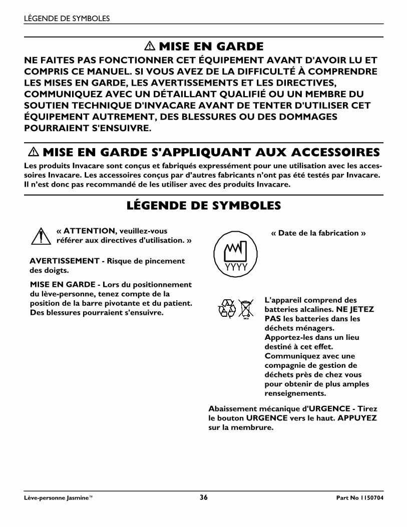
� MISE EN GARDENE FAITES PAS FONCTIONNER CET ÉQUIPEMENT AVANT D'AVOIR LU ET COMPRIS CE MANUEL. SI VOUS AVEZ DE LA DIFFICULTÉ À COMPRENDRE LES MISES EN GARDE, LES AVERTISSEMENTS ET LES DIRECTIVES, COMMUNIQUEZ AVEC UN DÉTAILLANT QUALIFIÉ OU UN MEMBRE DU SOUTIEN TECHNIQUE D'INVACARE AVANT DE TENTER D'UTILISER CET ÉQUIPEMENT AUTREMENT, DES BLESSURES OU DES DOMMAGES POURRAIENT S'ENSUIVRE.
� MISE EN GARDE S'APPLIQUANT AUX ACCESSOIRESLes produits Invacare sont conçus et fabriqués expressément pour une utilisation avec les acces-soires Invacare. Les accessoires conçus par d’autres fabricants n’ont pas été testés par Invacare. Il n’est donc pas recommandé de les utiliser avec des produits Invacare.
LÉGENDE DE SYMBOLES
« ATTENTION, veuillez-vous référer aux directives d'utilisation. »
AVERTISSEMENT - Risque de pincement des doigts.
MISE EN GARDE - Lors du positionnement du lève-personne, tenez compte de la position de la barre pivotante et du patient. Des blessures pourraient s'ensuivre.
« Date de la fabrication »
L'appareil comprend des batteries alcalines. NE JETEZ PAS les batteries dans les déchets ménagers. Apportez-les dans un lieu destiné à cet effet. Communiquez avec une compagnie de gestion de déchets près de chez vous pour obtenir de plus amples renseignements.
Abaissement mécanique d'URGENCE - Tirez le bouton URGENCE vers le haut. APPUYEZ sur la membrure.
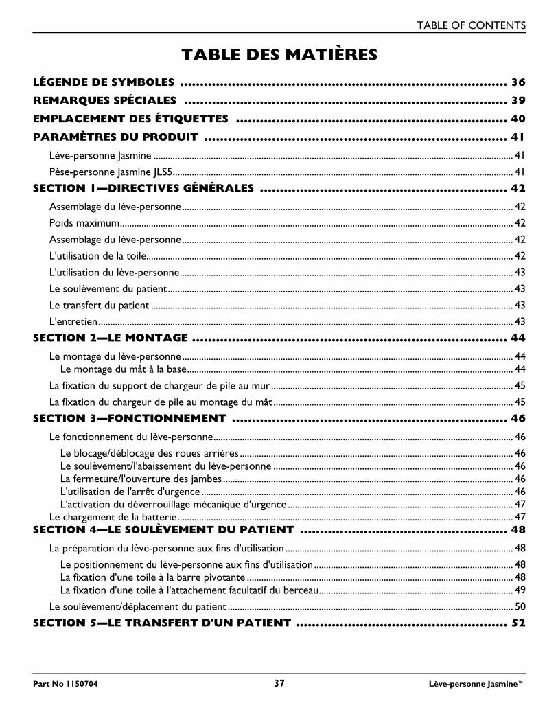
TABLE OF CONTENTS
TABLE DES MATIÈRES
LÉGENDE DE SYMBOLES .................................................................................. 36REMARQUES SPÉCIALES ................................................................................. 39
EMPLACEMENT DES ÉTIQUETTES .................................................................... 40
PARAMÈTRES DU PRODUIT ............................................................................ 41
Lève-personne Jasmine ...................................................................................................................................................... 41
Pèse-personne Jasmine JLS5.............................................................................................................................................. 41
SECTION 1—DIRECTIVES GÉNÉRALES .............................................................. 42
Assemblage du lève-personne.......................................................................................................................................... 42
Poids maximum.................................................................................................................................................................... 42
Assemblage du lève-personne.......................................................................................................................................... 42
L'utilisation de la toile......................................................................................................................................................... 42
L'utilisation du lève-personne........................................................................................................................................... 43
Le soulèvement du patient................................................................................................................................................ 43
Le transfert du patient ....................................................................................................................................................... 43
L'entretien............................................................................................................................................................................. 43
SECTION 2—LE MONTAGE ............................................................................... 44
Le montage du lève-personne .......................................................................................................................................... 44Le montage du mât à la base........................................................................................................................................ 44
La fixation du support de chargeur de pile au mur..................................................................................................... 45
La fixation du chargeur de pile au montage du mât .................................................................................................... 45
SECTION 3—FONCTIONNEMENT ..................................................................... 46
Le fonctionnement du lève-personne............................................................................................................................. 46
Le blocage/déblocage des roues arrières .................................................................................................................. 46Le soulèvement/l'abaissement du lève-personne .................................................................................................... 46La fermeture/l'ouverture des jambes ......................................................................................................................... 46L'utilisation de l'arrêt d'urgence .................................................................................................................................. 46L'activation du déverrouillage mécanique d'urgence .............................................................................................. 47
Le chargement de la batterie............................................................................................................................................ 47SECTION 4—LE SOULÈVEMENT DU PATIENT .................................................... 48
La préparation du lève-personne aux fins d'utilisation ............................................................................................... 48
Le positionnement du lève-personne aux fins d'utilisation ................................................................................... 48La fixation d'une toile à la barre pivotante ............................................................................................................... 48La fixation d'une toile à l'attachement facultatif du berceau................................................................................. 49
Le soulèvement/déplacement du patient ....................................................................................................................... 50
SECTION 5—LE TRANSFERT D'UN PATIENT ..................................................... 52
Part No 1150704 37 Lève-personne Jasmine™
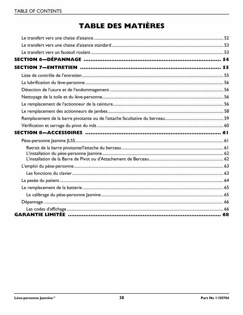
TABLE OF CONTENTS
TABLE DES MATIÈRES
Le transfert vers une chaise d'aisance ............................................................................................................................ 52Le transfert vers une chaise d'aisance standard ........................................................................................................... 53
Le transfert vers un fauteuil roulant ............................................................................................................................... 53
SECTION 6—DÉPANNAGE ............................................................................... 54
SECTION 7—ENTRETIEN ................................................................................. 55
Liste de contrôle de l’entretien ....................................................................................................................................... 55
La lubrification du lève-personne .................................................................................................................................... 56
Détection de l'usure et de l'endommagement ............................................................................................................. 56
Nettoyage de la toile et du lève-personne.................................................................................................................... 56
Le remplacement de l'actionneur de la ceinture.......................................................................................................... 56
Le remplacement des actionneurs de jambes............................................................................................................... 58
Remplacement de la barre pivotante ou de l'attache facultative du berceau........................................................ 59
Vérification et serrage du pivot du mât ......................................................................................................................... 60
SECTION 8—ACCESSOIRES .............................................................................. 61
Pèse-personne Jasmine JLS5.............................................................................................................................................. 61
Retrait de la barre pivotante/l'attache du berceau ................................................................................................. 61L'installation du pèse-personne Jasmine .................................................................................................................... 62L'installation de la Barre de Pivot ou d'Attachement de Berceau....................................................................... 62
L'emploi du pèse-personne ............................................................................................................................................... 63
Les fonctions du clavier................................................................................................................................................. 63
La pesée du patient ............................................................................................................................................................. 64
Le remplacement de la batterie ....................................................................................................................................... 65
Le calibrage du pèse-personne Jasmine ..................................................................................................................... 65
Dépannage ............................................................................................................................................................................ 66
Les codes d'affichage ...................................................................................................................................................... 66GARANTIE LIMITÉE ........................................................................................ 68
Lève-personne Jasmine™ 38 Part No 1150704
REMARQUES SPÉCIALES
Part No 1150704 39 Lève-personne Jasmine™
REMARQUES SPÉCIALESLes mots indicateurs utilisés dans ce manuel s'appliquent aux risques ou aux pratiques dangereuses pouvant provoquer des blessures corporelles ou des dommages matériels. Consultez le tableau ci-dessous pour connaître la définition des mots indicateurs.
� AVISL’INFORMATION CONTENUE DANS CE DOCUMENT PEUT ÊTRE MODIFIÉE SANS PRÉAVIS.INTERFÉRENCE AUX FRÉQUENCES RADIOÉLECTRIQUESL’interférence aux radio fréquences (IRF) influe sur la plupart des appareils électroniques. Il faut être PRUDENT lorsqu’on utilise de l’équipement de communication portatif à proximité de tels appareils. Si les IRF provoquent une instabilité, APPUYEZ sur l'interrupteur de pouvoir ROUGE en mode ARRÊT IMMÉDIATEMENT. N'APPUYEZ PAS sur l'interrupteur de pouvoir EN MARCHE lorsque la transmission est en cours.ENTRETIENSEULE une personne qualifiée DOIT exécuter l''entretien.
MOT INDICATEUR SIGNIFICATION
� DANGER Danger indique l’imminence d’une situation dangereuse qui pourrait causer de graves blessures, voire la mort, si elle n’est pas évitée.
� MISE EN GARDE Mise en garde indique l'éventualité d'une situation dangereuse qui pourrait causer de graves blessures, voire la mort si elle n'est pas évitée.
� AVERTISSEMENT Avertissement indique l'éventualité d'une situation dangereuse qui pourrait causer des dommages matériels ou des blessures légères, voire les deux si elle n'est pas évitée.
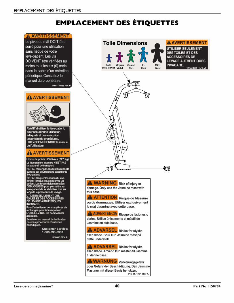
EMPLACEMENT DES ÉTIQUETTES
Lève-personne Jasmine™ 40 Part No 1150704
EMPLACEMENT DES ÉTIQUETTES
AVERTISSEMENT
AVERTISSEMENT
AVANT d’utiliser le lève-patient,pour assurer une utilisationadéquate et une exécution sécuritaire de procédures, LIRE et COMPRENDRE le manuel de l’utilisateur.
Limite de poids: 500 livres (227 Kg).
NE PAS rouler par-dessus les rebords surface qui pourrait faire basculer le lève-patient.NE PAS bloquer les roues du lève-patient lorsque vous soulevez un patient. Les roues doivent restées DÉBLOQUÉES pour permettre au lève-patient de se stabiliser tout au long de la procédure de levage. UTILISER SEULEMENT DES TOILES ET DES ACCESSOIRESDE LEVAGE AUTHENTIQUESINVACARE.
Se référer au manuel de l’utilisateur pour les procédures d’entretien périodiques.
Pour l’entretien et comme pièces derechanges pour le lève-patient,N’UTILISEZ QUE les composants adéquats.
Le lève-patient Invacare N’EST PAS un appareil de transport.
Customer Service:1-800-333-6900
1160880 REV. A
Le pivot du mât DOIT êtreserré pour une utilisationsans risque de votre lève-patient. Les vis DOIVENT être vérifiées au moins tous les six (6) mois dans le cadre d’un entretien périodique. Consultez le manuel du propriétaire.
P/N 1130265 Rev. B
AVERTISSEMENT
PetitBleu Marine
MoyenViolet
GrandVert
XLBleu
XXLNoir
AVERTISSEMENTUTILISER SEULEMENTDES TOILES ET DESACCESSOIRES DELEVAGE AUTHENTIQUES INVACARE.
Toile Dimensions
1160882 REV. A
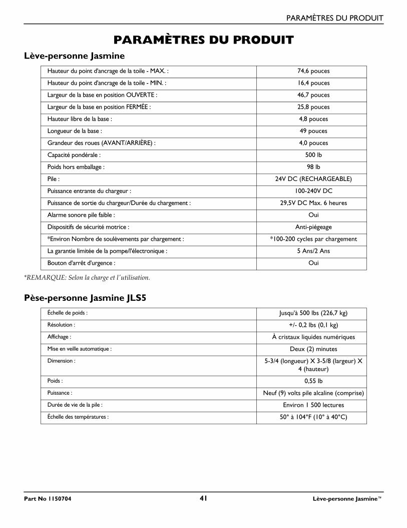
PARAMÈTRES DU PRODUIT
Part No 1150704 41 Lève-personne Jasmine™
PARAMÈTRES DU PRODUITLève-personne Jasmine
*REMARQUE: Selon la charge et l'utilisation.
Pèse-personne Jasmine JLS5
Hauteur du point d'ancrage de la toile - MAX. : 74,6 pouces
Hauteur du point d'ancrage de la toile - MIN. : 16,4 pouces
Largeur de la base en position OUVERTE : 46,7 pouces
Largeur de la base en position FERMÉE : 25,8 pouces
Hauteur libre de la base : 4,8 pouces
Longueur de la base : 49 pouces
Grandeur des roues (AVANT/ARRIÈRE) : 4,0 pouces
Capacité pondérale : 500 lb
Poids hors emballage : 98 lb
Pile : 24V DC (RECHARGEABLE)
Puissance entrante du chargeur : 100-240V DC
Puissance de sortie du chargeur/Durée du chargement : 29,5V DC Max. 6 heures
Alarme sonore pile faible : Oui
Dispositifs de sécurité motrice : Anti-piégeage
*Environ Nombre de soulèvements par chargement : *100-200 cycles par chargement
La garantie limitée de la pompe/l'électronique : 5 Ans/2 Ans
Bouton d'arrêt d'urgence : Oui
Échelle de poids : Jusqu'à 500 lbs (226,7 kg)
Résolution : +/- 0,2 lbs (0,1 kg)
Affichage : À cristaux liquides numériques
Mise en veille automatique : Deux (2) minutes
Dimension : 5-3/4 (longueur) X 3-5/8 (largeur) X 4 (hauteur)
Poids : 0,55 lb
Puissance : Neuf (9) volts pile alcaline (comprise)
Durée de vie de la pile : Environ 1 500 lectures
Échelle des températures : 50° à 104°F (10° à 40°C)
SECTION 1—DIRECTIVES GÉNÉRALES
SECTION 1—DIRECTIVES GÉNÉRALES
� MISE EN GARDESECTION 1 - DIRECTIVES GÉNÉRALES contient des renseignements importants sur le fonc-tionnement et l'utilisation sécuritaire de ce produit.
Voyez à ce que toutes les pièces soient en bon état avant d'utiliser l'appareil. Si les pièces sont endommagées, N'UTILISEZ PAS l'appareil. Veuillez contacter le détaillant pour de plus amples instructions.Le lève-personne d'Invacare N'EST PAS un dispositif de transport. Il est conçu pour transporter une personne d'une surface de repos à une autre (par exemple, d'un lit à un fauteuil roulant).NE tentez PAS de transférer un patient sans l'accord de son médecin, de l'infirmier ou du préposé. Lisez attentivement les instructions du manuel d'utilisateur, observez une équipe d'experts lors des procédures de soulèvement et ensuite effectuez l'ensemble de la procédure plusieurs fois sous surveillance tandis qu'un personne en bonne santé joue le rôle du patient.Les toiles et accessoires du lève-personne d'Invacare sont conçus spécialement pour être utilisés conjointement avec les lève-personnes d'Invacare. Les toiles et accessoires conçus par d'autres fabricants ne doivent pas être utilisés comme composantes du système de lève-personne d'Invacare.Si l'ascenseur patient est utilisé dans le secteur d'une douche ou d'un bain, garantir que l'ascenseur patient est essuyé propre de n'importe quelle humidité après l'usage. Ne PAS emmagasiner l'ascenseur dans un secteur humide ou dans une condition humide. Périodiquement inspecter tous composants de l'ascenseur patient pour les signes de corrosion. Remplacer toutes parties qui sont corrodées ou est endommagé.
Assemblage du lève-personneNE serrez PAS excessivement l'équipement de montage. Vous risquez d'abîmer les supports de fixation.
Poids maximumNE dépassez PAS le poids maximum du lève-personne. Le poids maximum du lève-personne Jasmine est de 500 lb.
Assemblage du lève-personneNE serrez PAS excessivement l'équipement de montage. Vous risquez d'abîmer les supports de fixation.
L'utilisation de la toileLe lève-personne Jasmine peut être utilisé avec la barre pivotante standard ou l'attache facultative du berceau. L'attache basculante du berceau permet à un seul préposé de placer plus facilement le patient bien assis en position verticale.Utilisez une toile approuvée par Invacare et recommandée par le médecin, l'infirmier ou le préposé du patient pour son propre confort et sa sécurité durant le soulèvement.Après chaque lessive (selon les instructions sur l'étiquette de la toile), inspectez les toiles pour vous assurer qu'il n'y ait pas d'usure, de déchirures ou de décousures.Des toiles javélisées, déchirées, coupées, effilochées ou brisées ne sont pas sécuritaires et peuvent causer des blessures. Jetez-les IMMÉDIATEMENT.NE modifiez PAS les toiles.Vérifiez les attaches des toiles chaque fois qu'une toile est retirée et remplacée pour vous assurer qu'elle soit bien en place avant que le patient soit déplacé d'un objet fixe (lit, chaise, chaise d'aisance).Si le patient est en fauteuil roulant, enclenchez le blocage des roues afin de prévenir le déplacement de la chaise.En fixant les toiles au lève-personne à l'aide des courroies à code-couleur, la courroie la plus courte DOIT être située à l'arrière du patient pour le soutenir. L'utilisation de la section longue procure peu ou pas de soutien au dos du patient. Les boucles de la toile à code-couleur peuvent être utilisées pour installer le patient dans diverses positions. Les couleurs facilitent la fixation égale de la toile sur les deux côtés. Assurez-vous que la tête du patient soit bien soutenue pendant le soulèvement.
Lève-personne Jasmine™ 42 Part No 1150704
SECTION 1—DIRECTIVES GÉNÉRALES
L'utilisation du lève-personneMême si Invacare recommande que deux préposés soient présents pour toute préparation au soulèvement et pour les procédures de transfert du patient, notre équipement peut être correctement manipulé par un seul préposé. Le professionnel de la santé établit la présence d'un seul préposé selon chaque cas.Assurez-vous d'entendre le déclic lors du montage de la pile sur le chargeur de pile pour vous assurer qu'elle est bien en place. Autrement, des blessures ou des dommages pourraient s’ensuivre.Éloignez TOUJOURS les mains et les doigts des pièces mobiles pour éviter les blessures.
Le soulèvement du patientTout ajustement visant à assurer la sécurité et le confort devraient être effectués avant de déplacer le patient. Les bras du patient devrait se trouver à l'intérieur des courroies.Avant de transférer un patient à partir d'un objet fixe (fauteuil roulant, chaise d'aisance ou lit), soulevez légèrement le patient de cet espace et vérifiez que les attaches de la toile soient bien en place. Si une attache n'est pas fixée correctement, abaissez le patient, rectifiez le problème et vérifiez de nouveau.Pendant le transfert, lorsque le patient est suspendu à une toile attachée au lève-personne, NE passez PAS la base à roues sur surface inégale qui pourrait créer un déséquilibre et faire tomber l'appareil. Utilisez les poignées de direction du mât EN TOUT TEMPS pour pousser et tirer le lève-personne.
Le transfert du patientAvant de transférer un patient, assurez-vous que le poids du patient ne dépasse pas le poids maximum de l'appareil.Avant de transférer un patient à partir d'un objet fixe (fauteuil roulant, chaise d'aisance ou lit), soulevez légèrement le patient de cet espace et vérifiez que les attaches de la toile soient bien en place. Si une attache n'est pas fixée correctement, abaissez le patient, rectifiez le problème et vérifiez de nouveau.Avant de transférer un patient, assurez-vous que le poids du patient ne dépasse pas le poids maximal de l'appareil.Le blocage des roues du fauteuil roulant DOIT être enclenché avant d'abaisser le patient dans le fauteuil roulant aux fins de déplacement.Vérifiez les attaches des toiles chaque fois qu'une toile est retirée et remplacée afin de vous assurer qu'elle soit bien en place avant que le patient soit déplacé d'un lit ou d'une chaise.Le boulon de pivot du mât DOIT être resserré afin d'assurer l'utilisation sécuritaire du lève-personne. Le boulon DOIT être vérifié au moins une fois tous les six mois lors d'un entretien périodique.
L'entretienL'entretien régulier des lève-personnes et des accessoires est nécessaire afin d'assurer un bon fonctionnement.Après les douze premiers mois d'utilisation, vérifiez que les pivots et les attaches ne soient pas usés. Si le métal est usé, la pièce DOIT être remplacée. Effectuez cette vérification tous les six mois par la suite.Les roues et les boulons d'essieu requièrent une inspection tous les six mois contre le serrage et l'usure.
Part No 1150704 43 Lève-personne Jasmine™
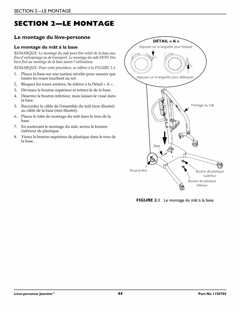
SECTION 2—LE MONTAGE
SECTION 2—LE MONTAGE
Le montage du lève-personne
Le montage du mât à la baseREMARQUE: Le montage du mât peut être retiré de la base aux fins d'entreposage ou de transport. Le montage du mât DOIT être bien fixé au montage de la base avant l'utilisation.REMARQUE: Pour cette procédure, se référer à la FIGURE 2.1.1. Placez la base sur une surface nivelée pour assurer que
toutes les roues touchent au sol.2. Bloquez les roues arrières. Se référer à la Détail « A ».3. Dévissez le bouton supérieur et retirez-le de la base.4. Déserrez le bouton inférieur, mais laissez-le vissé dans
la base.5. Raccordez le câble de l’ensemble du mât (non illustré)
au câble de la base (non illustré).6. Placez le tube de montage du mât dans le trou de la
base.7. En soutenant le montage du mât, serrez le bouton
inférieur de plastique.8. Vissez le bouton supérieur de plastique dans le trou de
la base.
FIGURE 2.1 Le montage du mât à la base
Appuyez sur la languette pour bloquer
Appuyez sur la languette pour débloquer
DÉTAIL « A »
Roue arrière
Montage du mât
Bouton de plastique supérieur
Base
Bouton de plastique inférieur
Lève-personne Jasmine™ 44 Part No 1150704
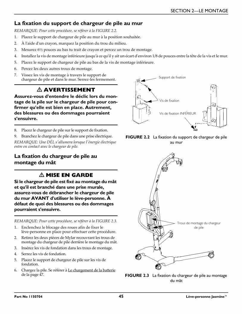
SECTION 2—LE MONTAGE
La fixation du support de chargeur de pile au murREMARQUE: Pour cette procédure, se référer à la FIGURE 2.2.1. Placez le support de chargeur de pile au mur à la position souhaitée.2. À l'aide d'un crayon, marquez la position du trou du milieu.3. Mesurez 6½ pouces au bas tu trait de crayon et percez un trou de montage.4. Installez la vis de montage inférieure jusqu'à ce qu'il y ait un écart d'environ 1/8 de pouces entre la tête de la vis et le mur.5. Placez le support de chargeur de pile au bas de la vis de montage inférieure.6. Percez les deux autres trous de montage.7. Vissez les vis de montage à travers le support de
chargeur de pile et dans le mur. Serrez-les fermement.
� AVERTISSEMENTAssurez-vous d'entendre le déclic lors du mon-tage de la pile sur le chargeur de pile pour con-firmer qu'elle est bien en place. Autrement, des blessures ou des dommages pourraient s’ensuivre.
8. Placez le chargeur de pile sur le support de fixation.9. Branchez le chargeur de pile dans une prise électrique.REMARQUE: Une DÉL s'allumera lorsque l'énergie électrique entre en contact avec le chargeur de pile.
La fixation du chargeur de pile au montage du mât
� MISE EN GARDESi le chargeur de pile est fixé au montage du mât et qu'il est branché dans une prise murale, assurez-vous de débrancher le chargeur de pile du mur AVANT d'utiliser le lève-personne. À défaut de quoi des blessures ou des dommages pourraient s’ensuivre.
REMARQUE: Pour cette procédure, se référer à la FIGURE 2.3.1. Enclenchez le blocage des roues afin de fixer le
lève-personne en place pour effectuer cette procédure.2. Retirez les deux pièces de Mylar recouvrant les trous de
montage du chargeur de pile derrière le montage du mât.3. Insérez les vis de fondation dans les trous de montage.4. Serrez les vis de fondation.5. Placez le support de chargeur de pile sur les vis de
fondation.6. Chargez la pile. Se référer à Le chargement de la batterie
de la page 47.
FIGURE 2.2 La fixation du support de chargeur de pile au mur
FIGURE 2.3 La fixation du chargeur de pile au montage du mât
Support de fixation
Vis de fixation
Vis de fixation INFÉRIEUR
Trous de montage du chargeur de pile
Part No 1150704 45 Lève-personne Jasmine™
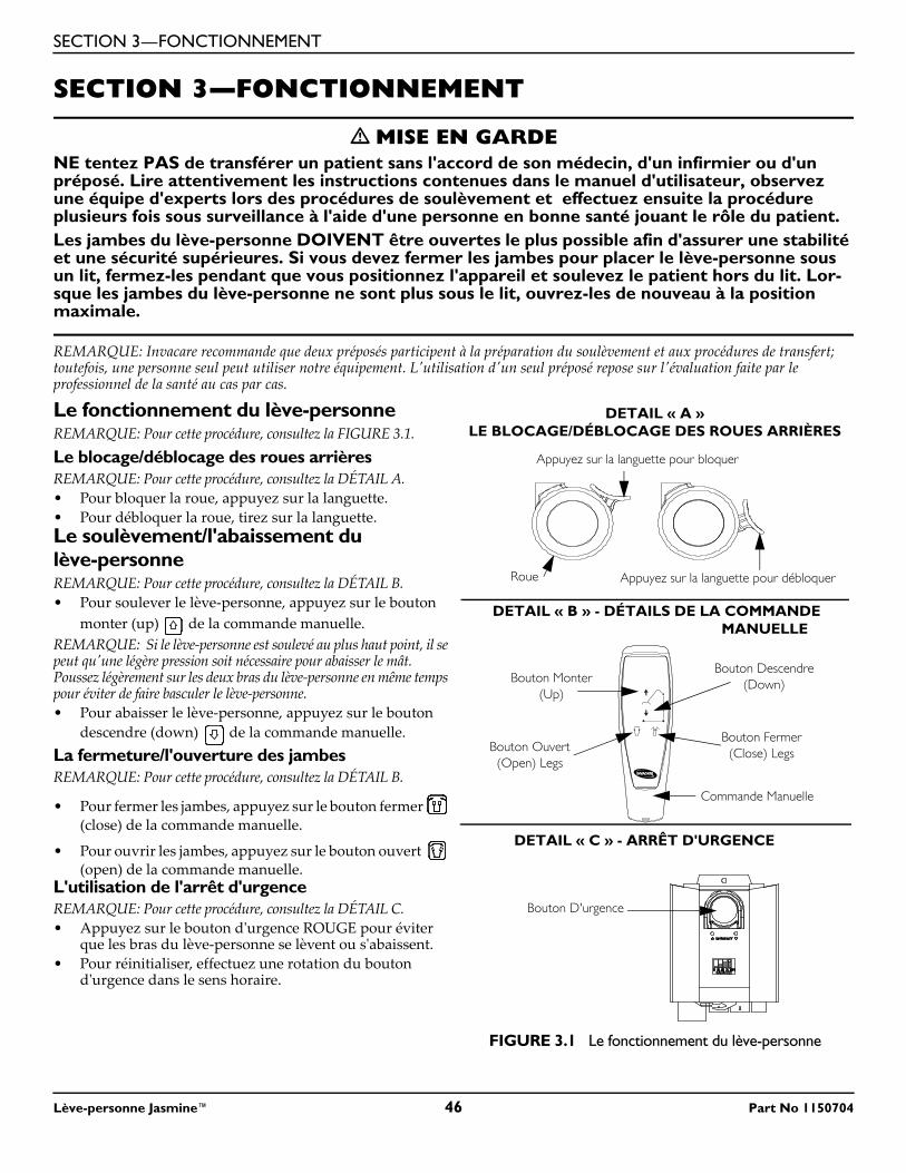
SECTION 3—FONCTIONNEMENT
SECTION 3—FONCTIONNEMENT
� MISE EN GARDENE tentez PAS de transférer un patient sans l'accord de son médecin, d'un infirmier ou d'un préposé. Lire attentivement les instructions contenues dans le manuel d'utilisateur, observez une équipe d'experts lors des procédures de soulèvement et effectuez ensuite la procédure plusieurs fois sous surveillance à l'aide d'une personne en bonne santé jouant le rôle du patient.Les jambes du lève-personne DOIVENT être ouvertes le plus possible afin d'assurer une stabilité et une sécurité supérieures. Si vous devez fermer les jambes pour placer le lève-personne sous un lit, fermez-les pendant que vous positionnez l'appareil et soulevez le patient hors du lit. Lor-sque les jambes du lève-personne ne sont plus sous le lit, ouvrez-les de nouveau à la position maximale.
REMARQUE: Invacare recommande que deux préposés participent à la préparation du soulèvement et aux procédures de transfert; toutefois, une personne seul peut utiliser notre équipement. L'utilisation d'un seul préposé repose sur l'évaluation faite par le professionnel de la santé au cas par cas.
Le fonctionnement du lève-personneREMARQUE: Pour cette procédure, consultez la FIGURE 3.1.Le blocage/déblocage des roues arrièresREMARQUE: Pour cette procédure, consultez la DÉTAIL A.• Pour bloquer la roue, appuyez sur la languette.• Pour débloquer la roue, tirez sur la languette.Le soulèvement/l'abaissement du lève-personneREMARQUE: Pour cette procédure, consultez la DÉTAIL B.• Pour soulever le lève-personne, appuyez sur le bouton
monter (up) de la commande manuelle.REMARQUE: Si le lève-personne est soulevé au plus haut point, il se peut qu'une légère pression soit nécessaire pour abaisser le mât. Poussez légèrement sur les deux bras du lève-personne en même temps pour éviter de faire basculer le lève-personne.• Pour abaisser le lève-personne, appuyez sur le bouton
descendre (down) de la commande manuelle.La fermeture/l'ouverture des jambesREMARQUE: Pour cette procédure, consultez la DÉTAIL B.
• Pour fermer les jambes, appuyez sur le bouton fermer (close) de la commande manuelle.
• Pour ouvrir les jambes, appuyez sur le bouton ouvert (open) de la commande manuelle.
L'utilisation de l'arrêt d'urgenceREMARQUE: Pour cette procédure, consultez la DÉTAIL C.• Appuyez sur le bouton d'urgence ROUGE pour éviter
que les bras du lève-personne se lèvent ou s'abaissent.• Pour réinitialiser, effectuez une rotation du bouton
d'urgence dans le sens horaire.
FIGURE 3.1 Le fonctionnement du lève-personne
Appuyez sur la languette pour bloquer
Appuyez sur la languette pour débloquerRoue
DETAIL « A »LE BLOCAGE/DÉBLOCAGE DES ROUES ARRIÈRES
DETAIL « B » - DÉTAILS DE LA COMMANDE MANUELLE
DETAIL « C » - ARRÊT D'URGENCE
Bouton Fermer (Close) Legs
Bouton Monter (Up)
Commande Manuelle
Bouton D'urgence
Bouton Ouvert(Open) Legs
Bouton Descendre (Down)
Lève-personne Jasmine™ 46 Part No 1150704
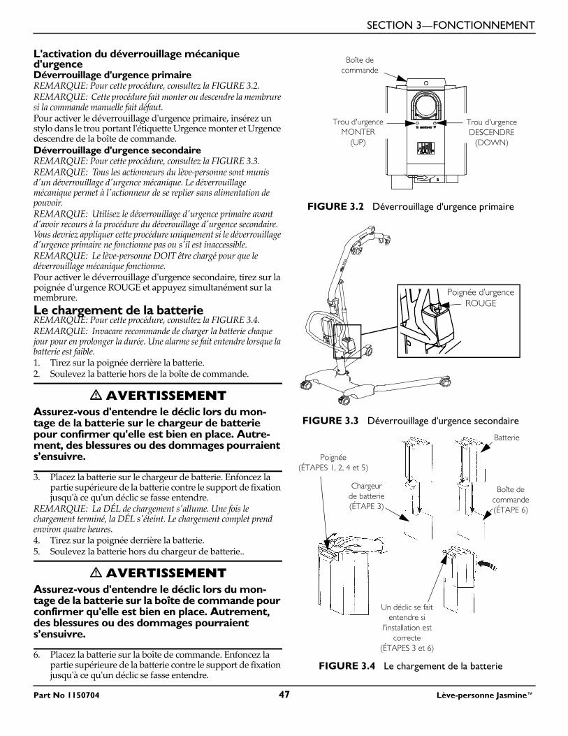
SECTION 3—FONCTIONNEMENT
L'activation du déverrouillage mécanique d'urgenceDéverrouillage d'urgence primaireREMARQUE: Pour cette procédure, consultez la FIGURE 3.2.REMARQUE: Cette procédure fait monter ou descendre la membrure si la commande manuelle fait défaut.Pour activer le déverrouillage d'urgence primaire, insérez un stylo dans le trou portant l'étiquette Urgence monter et Urgence descendre de la boîte de commande.Déverrouillage d'urgence secondaireREMARQUE: Pour cette procédure, consultez la FIGURE 3.3.REMARQUE: Tous les actionneurs du lève-personne sont munis d'un déverrouillage d'urgence mécanique. Le déverrouillage mécanique permet à l'actionneur de se replier sans alimentation de pouvoir.REMARQUE: Utilisez le déverrouillage d'urgence primaire avant d'avoir recours à la procédure du déverouillage d'urgence secondaire. Vous devriez appliquer cette procédure uniquement si le déverrouillage d'urgence primaire ne fonctionne pas ou s'il est inaccessible.REMARQUE: Le lève-personne DOIT être chargé pour que le déverrouillage mécanique fonctionne.Pour activer le déverrouillage d'urgence secondaire, tirez sur la poignée d'urgence ROUGE et appuyez simultanément sur la membrure.Le chargement de la batterieREMARQUE: Pour cette procédure, consultez la FIGURE 3.4.REMARQUE: Invacare recommande de charger la batterie chaque jour pour en prolonger la durée. Une alarme se fait entendre lorsque la batterie est faible.1. Tirez sur la poignée derrière la batterie.2. Soulevez la batterie hors de la boîte de commande.
� AVERTISSEMENTAssurez-vous d'entendre le déclic lors du mon-tage de la batterie sur le chargeur de batterie pour confirmer qu'elle est bien en place. Autre-ment, des blessures ou des dommages pourraient s’ensuivre.
3. Placez la batterie sur le chargeur de batterie. Enfoncez la partie supérieure de la batterie contre le support de fixation jusqu'à ce qu'un déclic se fasse entendre.
REMARQUE: La DÉL de chargement s'allume. Une fois le chargement terminé, la DÉL s'éteint. Le chargement complet prend environ quatre heures.4. Tirez sur la poignée derrière la batterie.5. Soulevez la batterie hors du chargeur de batterie..
� AVERTISSEMENTAssurez-vous d'entendre le déclic lors du mon-tage de la batterie sur la boîte de commande pour confirmer qu'elle est bien en place. Autrement, des blessures ou des dommages pourraient s’ensuivre.
6. Placez la batterie sur la boîte de commande. Enfoncez la partie supérieure de la batterie contre le support de fixation jusqu'à ce qu'un déclic se fasse entendre.
FIGURE 3.2 Déverrouillage d'urgence primaire
FIGURE 3.3 Déverrouillage d'urgence secondaire
FIGURE 3.4 Le chargement de la batterie
Boîte de commande
Trou d'urgence DESCENDRE
(DOWN)
Trou d'urgence MONTER
(UP)
Poignée d’urgence ROUGE
Chargeur de batterie (ÉTAPE 3)
Boîte de commande (ÉTAPE 6)
Un déclic se fait entendre si
l'installation est correcte
(ÉTAPES 3 et 6)
Poignée (ÉTAPES 1, 2, 4 et 5)
Batterie
Part No 1150704 47 Lève-personne Jasmine™
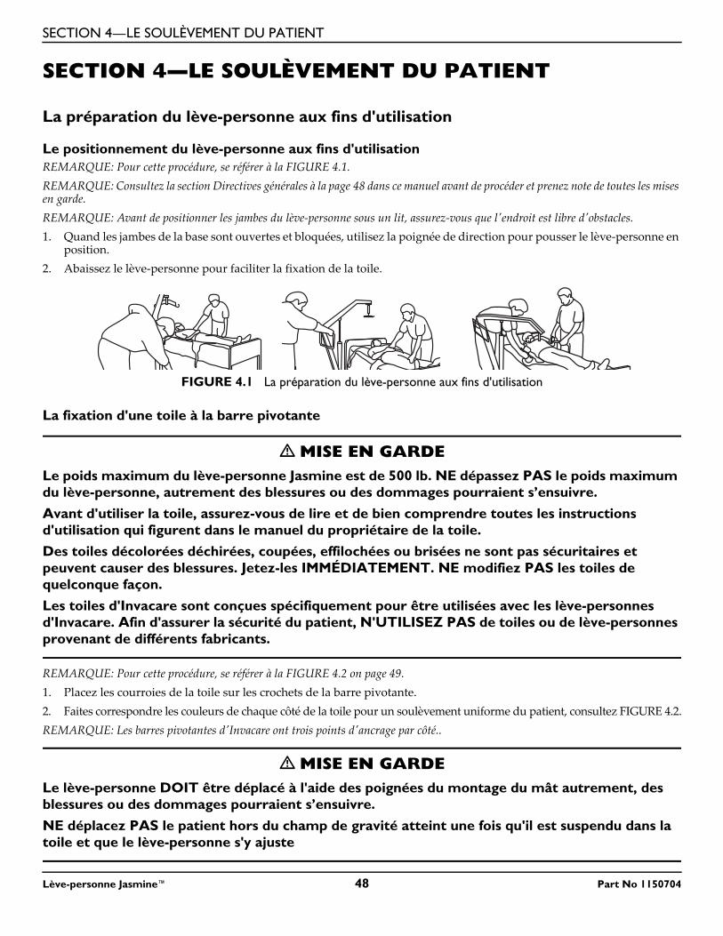
SECTION 4—LE SOULÈVEMENT DU PATIENT
SECTION 4—LE SOULÈVEMENT DU PATIENT
La préparation du lève-personne aux fins d'utilisation
Le positionnement du lève-personne aux fins d'utilisationREMARQUE: Pour cette procédure, se référer à la FIGURE 4.1.REMARQUE: Consultez la section Directives générales à la page 48 dans ce manuel avant de procéder et prenez note de toutes les mises en garde.REMARQUE: Avant de positionner les jambes du lève-personne sous un lit, assurez-vous que l'endroit est libre d'obstacles.1. Quand les jambes de la base sont ouvertes et bloquées, utilisez la poignée de direction pour pousser le lève-personne en
position.2. Abaissez le lève-personne pour faciliter la fixation de la toile.
FIGURE 4.1 La préparation du lève-personne aux fins d'utilisation
La fixation d'une toile à la barre pivotante
� MISE EN GARDELe poids maximum du lève-personne Jasmine est de 500 lb. NE dépassez PAS le poids maximum du lève-personne, autrement des blessures ou des dommages pourraient s’ensuivre.Avant d'utiliser la toile, assurez-vous de lire et de bien comprendre toutes les instructions d'utilisation qui figurent dans le manuel du propriétaire de la toile.Des toiles décolorées déchirées, coupées, effilochées ou brisées ne sont pas sécuritaires et peuvent causer des blessures. Jetez-les IMMÉDIATEMENT. NE modifiez PAS les toiles de quelconque façon.Les toiles d'Invacare sont conçues spécifiquement pour être utilisées avec les lève-personnes d'Invacare. Afin d'assurer la sécurité du patient, N'UTILISEZ PAS de toiles ou de lève-personnes provenant de différents fabricants.
REMARQUE: Pour cette procédure, se référer à la FIGURE 4.2 on page 49.1. Placez les courroies de la toile sur les crochets de la barre pivotante. 2. Faites correspondre les couleurs de chaque côté de la toile pour un soulèvement uniforme du patient, consultez FIGURE 4.2.REMARQUE: Les barres pivotantes d'Invacare ont trois points d'ancrage par côté..
� MISE EN GARDELe lève-personne DOIT être déplacé à l'aide des poignées du montage du mât autrement, des blessures ou des dommages pourraient s’ensuivre.NE déplacez PAS le patient hors du champ de gravité atteint une fois qu'il est suspendu dans la toile et que le lève-personne s'y ajuste
Lève-personne Jasmine™ 48 Part No 1150704
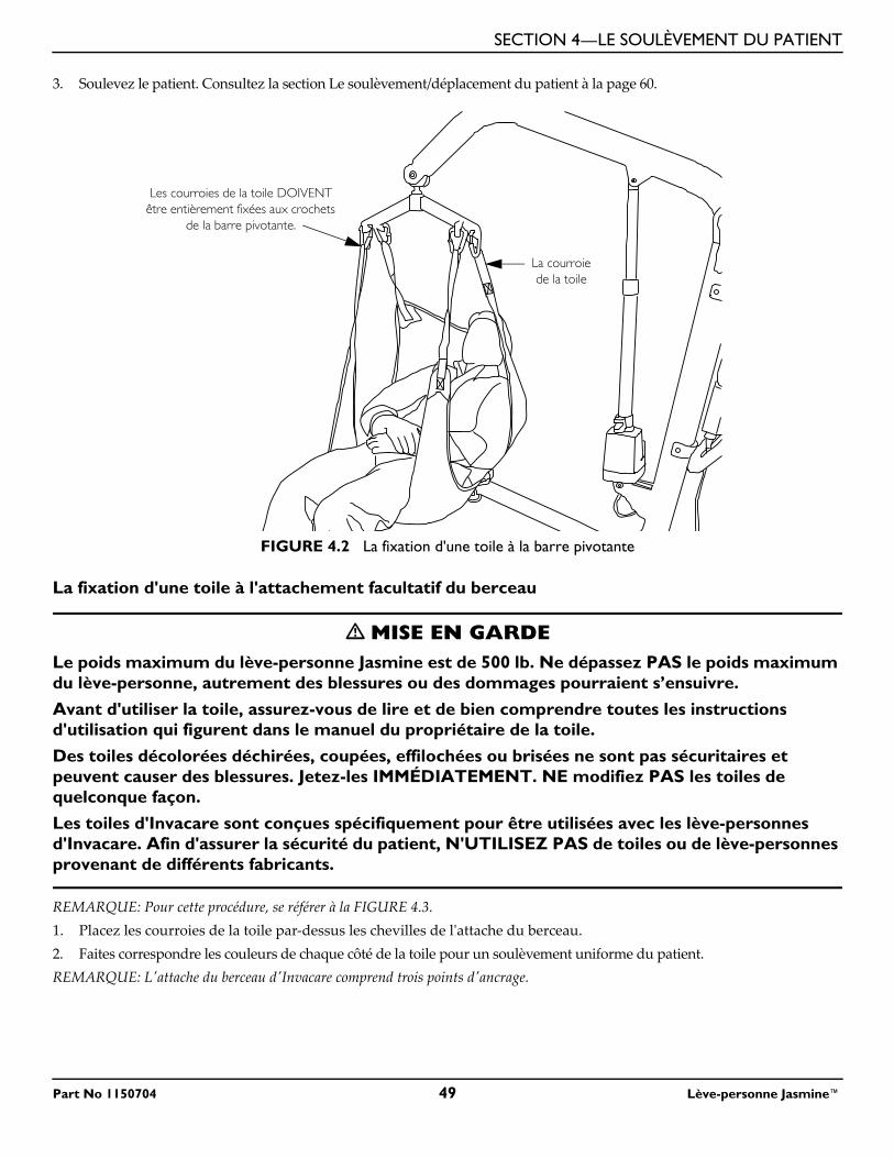
SECTION 4—LE SOULÈVEMENT DU PATIENT
3. Soulevez le patient. Consultez la section Le soulèvement/déplacement du patient à la page 60.
FIGURE 4.2 La fixation d'une toile à la barre pivotante
La fixation d'une toile à l'attachement facultatif du berceau
� MISE EN GARDELe poids maximum du lève-personne Jasmine est de 500 lb. Ne dépassez PAS le poids maximum du lève-personne, autrement des blessures ou des dommages pourraient s’ensuivre.Avant d'utiliser la toile, assurez-vous de lire et de bien comprendre toutes les instructions d'utilisation qui figurent dans le manuel du propriétaire de la toile.
Des toiles décolorées déchirées, coupées, effilochées ou brisées ne sont pas sécuritaires et peuvent causer des blessures. Jetez-les IMMÉDIATEMENT. NE modifiez PAS les toiles de quelconque façon.Les toiles d'Invacare sont conçues spécifiquement pour être utilisées avec les lève-personnes d'Invacare. Afin d'assurer la sécurité du patient, N'UTILISEZ PAS de toiles ou de lève-personnes provenant de différents fabricants.
REMARQUE: Pour cette procédure, se référer à la FIGURE 4.3.1. Placez les courroies de la toile par-dessus les chevilles de l'attache du berceau. 2. Faites correspondre les couleurs de chaque côté de la toile pour un soulèvement uniforme du patient.REMARQUE: L'attache du berceau d'Invacare comprend trois points d'ancrage.
Les courroies de la toile DOIVENT être entièrement fixées aux crochets
de la barre pivotante.
La courroie de la toile
Part No 1150704 49 Lève-personne Jasmine™
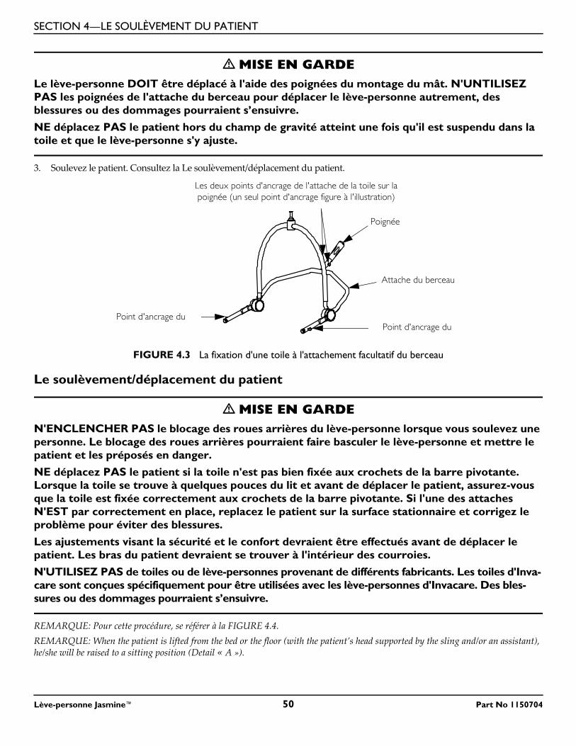
SECTION 4—LE SOULÈVEMENT DU PATIENT
� MISE EN GARDELe lève-personne DOIT être déplacé à l'aide des poignées du montage du mât. N'UNTILISEZ PAS les poignées de l'attache du berceau pour déplacer le lève-personne autrement, des blessures ou des dommages pourraient s’ensuivre.NE déplacez PAS le patient hors du champ de gravité atteint une fois qu'il est suspendu dans la toile et que le lève-personne s'y ajuste.
3. Soulevez le patient. Consultez la Le soulèvement/déplacement du patient.
FIGURE 4.3 La fixation d'une toile à l'attachement facultatif du berceau
Le soulèvement/déplacement du patient
� MISE EN GARDEN'ENCLENCHER PAS le blocage des roues arrières du lève-personne lorsque vous soulevez une personne. Le blocage des roues arrières pourraient faire basculer le lève-personne et mettre le patient et les préposés en danger.NE déplacez PAS le patient si la toile n'est pas bien fixée aux crochets de la barre pivotante. Lorsque la toile se trouve à quelques pouces du lit et avant de déplacer le patient, assurez-vous que la toile est fixée correctement aux crochets de la barre pivotante. Si l'une des attaches N'EST par correctement en place, replacez le patient sur la surface stationnaire et corrigez le problème pour éviter des blessures.Les ajustements visant la sécurité et le confort devraient être effectués avant de déplacer le patient. Les bras du patient devraient se trouver à l'intérieur des courroies.N'UTILISEZ PAS de toiles ou de lève-personnes provenant de différents fabricants. Les toiles d'Inva-care sont conçues spécifiquement pour être utilisées avec les lève-personnes d'Invacare. Des bles-sures ou des dommages pourraient s’ensuivre.
REMARQUE: Pour cette procédure, se référer à la FIGURE 4.4.REMARQUE: When the patient is lifted from the bed or the floor (with the patient’s head supported by the sling and/or an assistant), he/she will be raised to a sitting position (Detail « A »).
Attache du berceau
Point d'ancrage du
Les deux points d'ancrage de l'attache de la toile sur la poignée (un seul point d'ancrage figure à l'illustration)
Poignée
Point d'ancrage du
Lève-personne Jasmine™ 50 Part No 1150704
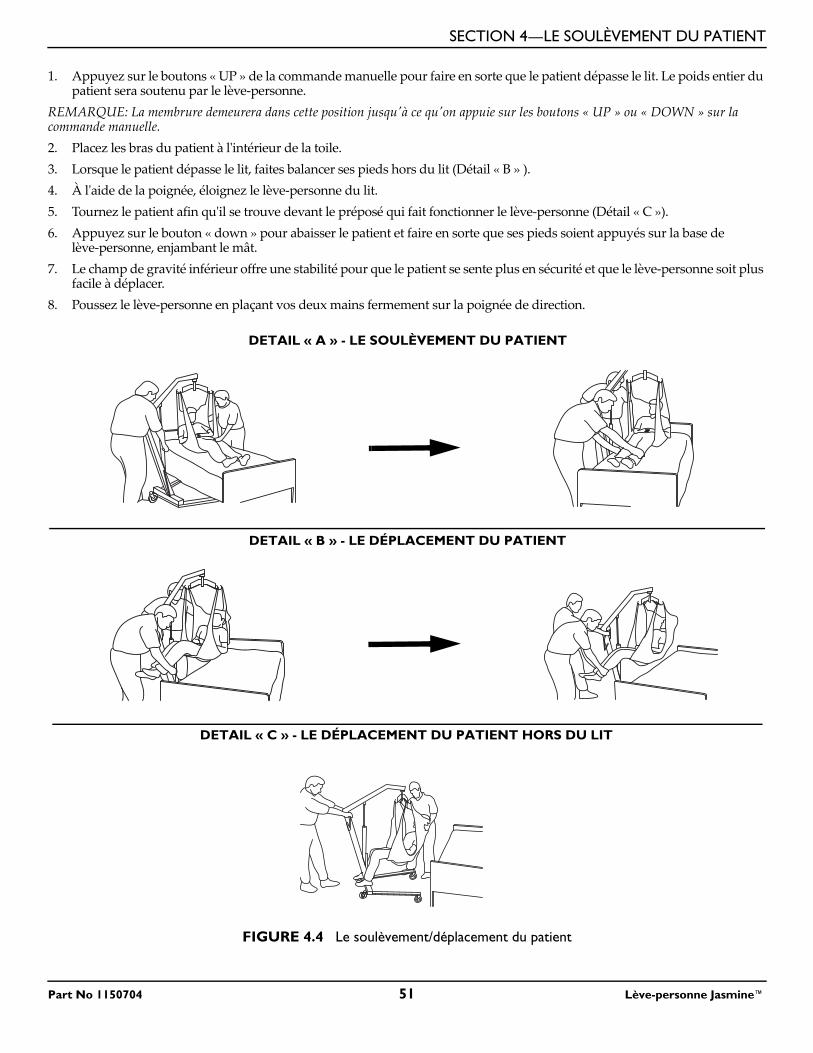
SECTION 4—LE SOULÈVEMENT DU PATIENT
1. Appuyez sur le boutons « UP » de la commande manuelle pour faire en sorte que le patient dépasse le lit. Le poids entier du patient sera soutenu par le lève-personne.
REMARQUE: La membrure demeurera dans cette position jusqu'à ce qu'on appuie sur les boutons « UP » ou « DOWN » sur la commande manuelle.2. Placez les bras du patient à l'intérieur de la toile.3. Lorsque le patient dépasse le lit, faites balancer ses pieds hors du lit (Détail « B » ).4. À l'aide de la poignée, éloignez le lève-personne du lit.5. Tournez le patient afin qu'il se trouve devant le préposé qui fait fonctionner le lève-personne (Détail « C »).6. Appuyez sur le bouton « down » pour abaisser le patient et faire en sorte que ses pieds soient appuyés sur la base de
lève-personne, enjambant le mât.7. Le champ de gravité inférieur offre une stabilité pour que le patient se sente plus en sécurité et que le lève-personne soit plus
facile à déplacer.8. Poussez le lève-personne en plaçant vos deux mains fermement sur la poignée de direction.
FIGURE 4.4 Le soulèvement/déplacement du patient
DETAIL « A » - LE SOULÈVEMENT DU PATIENT
DETAIL « B » - LE DÉPLACEMENT DU PATIENT
DETAIL « C » - LE DÉPLACEMENT DU PATIENT HORS DU LIT
Part No 1150704 51 Lève-personne Jasmine™
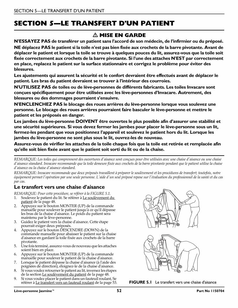
SECTION 5—LE TRANSFERT D'UN PATIENT
SECTION 5—LE TRANSFERT D'UN PATIENT
� MISE EN GARDEN'ESSAYEZ PAS de transférer un patient sans l'accord de son médecin, de l'infirmier ou du préposé. NE déplacez PAS le patient si la toile n'est pas bien fixée aux crochets de la barre pivotante. Avant de déplacer le patient et lorsque la toile se trouve à quelques pouces du lit, assurez-vous que la toile soit fixée correctement aux crochets de la barre pivotante. Si l'une des attaches N'EST par correctement en place, replacez le patient sur la surface stationnaire et corrigez le problème pour éviter des blessures.Les ajustements qui assurent la sécurité et le confort devraient être effectués avant de déplacer le patient. Les bras du patient devraient se trouver à l'intérieur des courroies.N'UTILISEZ PAS de toiles ou de lève-personnes de différents fabricants. Les toiles Invacare sont conçues spécifiquement pour être utilisées avec les lève-personnes d'Invacare. Autrement, des blessures ou des dommages pourraient s’ensuivre.N'ENCLENCHEZ PAS le blocage des roues arrières du lève-personne lorsque vous soulevez une personne. Le blocage des roues arrières pourraient faire basculer le lève-personne et mettre le patient et les préposés en danger.Les jambes du lève-personne DOIVENT être ouvertes le plus possible afin d'assurer une stabilité et une sécurité supérieures. Si vous devez fermer les jambes pour placer le lève-personne sous un lit, fermez-les pendant que vous positionnez l'appareil et soulevez le patient hors du lit. Lorsque les jambes du lève-personne ne sont plus sous le lit, ouvrez-les de nouveau.Assurez-vous de vérifier les attaches de la toile chaque fois que la toile est retirée et remplacée afin qu'elle soit bien fixée avant que le patient soit sorti du lit ou de la chaise.
REMARQUE: Les toiles qui comprennent des ouvertures d'aisance sont conçues pour être utilisées avec une chaise d'aisance ou une chaise d'aisance standard. Invacare recommande que la toile demeure fixée aux crochets de la barre pivotante pendant que le patient utilise la chaise d'aisance ou la chaise d'aisance standard.REMARQUE: Invacare recommande que deux préposés travaillent à préparer le soulèvement et les procédures de transfert; toutefois, notre équipement permet l'opération par une seule personne. L'aide d'un seul préposé repose sur l'évaluation du professionnel de la santé et du cas par cas.Le transfert vers une chaise d'aisanceREMARQUE: Pour cette procédure, se référer à la FIGURE 5.1.1. Soulevez le patient du lit. Se référer à Le soulèvement du
patient de la page 48.2. Appuyez sur le bouton MONTER (UP) de la commande
manuelle pour soulever le patient jusqu'à ce qu'il dépasse les bras de la chaise d'aisance. Le poids du patient sera maintenu par le lève-personne.
3. Guidez le patient vers la chaise d'aisance. Cette étape pourrait exiger deux préposés.
4. Appuyez sur le bouton DESCENDRE (DOWN) de la commande manuelle pour abaisser le patient sur la chaise d'aisance en gardant la toile fixée aux crochets de la barre pivotante.
5. Une fois terminé, assurez-vous de nouveau que les attaches soient bien en place.
6. Appuyez sur le bouton MONTER (UP) de la commande manuelle pour soulever le patient de la chaise d'aisance.
7. Lorsque le patient dépasse la chaise d'aisance (à l'aide des poignées de direction), éloignez-le de la chaise d'aisance.
8. Si vous voulez retourner le patient au lit, inversez les étapes de la section Le soulèvement du patient de la page 48.
9. Si vous voulez placer le patient dans un fauteuil roulant, Se référer à Le transfert vers un fauteuil roulant de la page 53. FIGURE 5.1 Le transfert vers une chaise d'aisance
Lève-personne Jasmine™ 52 Part No 1150704
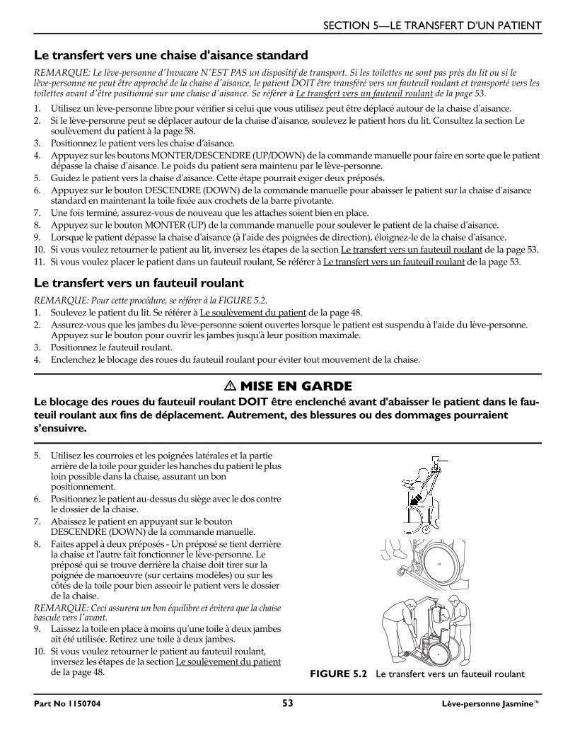
SECTION 5—LE TRANSFERT D'UN PATIENT
Le transfert vers une chaise d'aisance standardREMARQUE: Le lève-personne d'Invacare N'EST PAS un dispositif de transport. Si les toilettes ne sont pas près du lit ou si le lève-personne ne peut être approché de la chaise d'aisance, le patient DOIT être transféré vers un fauteuil roulant et transporté vers les toilettes avant d'être positionné sur une chaise d'aisance. Se référer à Le transfert vers un fauteuil roulant de la page 53.1. Utilisez un lève-personne libre pour vérifier si celui que vous utilisez peut être déplacé autour de la chaise d'aisance.2. Si le lève-personne peut se déplacer autour de la chaise d'aisance, soulevez le patient hors du lit. Consultez la section Le
soulèvement du patient à la page 58.3. Positionnez le patient vers les chaise d’aisance.4. Appuyez sur les boutons MONTER/DESCENDRE (UP/DOWN) de la commande manuelle pour faire en sorte que le patient
dépasse la chaise d'aisance. Le poids du patient sera maintenu par le lève-personne.5. Guidez le patient vers la chaise d'aisance. Cette étape pourrait exiger deux préposés.6. Appuyez sur le bouton DESCENDRE (DOWN) de la commande manuelle pour abaisser le patient sur la chaise d'aisance
standard en maintenant la toile fixée aux crochets de la barre pivotante.7. Une fois terminé, assurez-vous de nouveau que les attaches soient bien en place.8. Appuyez sur le bouton MONTER (UP) de la commande manuelle pour soulever le patient de la chaise d'aisance.9. Lorsque le patient dépasse la chaise d'aisance (à l'aide des poignées de direction), éloignez-le de la chaise d'aisance.10. Si vous voulez retourner le patient au lit, inversez les étapes de la section Le transfert vers un fauteuil roulant de la page 53.11. Si vous voulez placer le patient dans un fauteuil roulant, Se référer à Le transfert vers un fauteuil roulant de la page 53.
Le transfert vers un fauteuil roulantREMARQUE: Pour cette procédure, se référer à la FIGURE 5.2.1. Soulevez le patient du lit. Se référer à Le soulèvement du patient de la page 48.2. Assurez-vous que les jambes du lève-personne soient ouvertes lorsque le patient est suspendu à l'aide du lève-personne.
Appuyez sur le bouton pour ouvrir les jambes jusqu'à leur position maximale.3. Positionnez le fauteuil roulant.4. Enclenchez le blocage des roues du fauteuil roulant pour éviter tout mouvement de la chaise.
� MISE EN GARDELe blocage des roues du fauteuil roulant DOIT être enclenché avant d'abaisser le patient dans le fau-teuil roulant aux fins de déplacement. Autrement, des blessures ou des dommages pourraient s’ensuivre.
5. Utilisez les courroies et les poignées latérales et la partie arrière de la toile pour guider les hanches du patient le plus loin possible dans la chaise, assurant un bon positionnement.
6. Positionnez le patient au-dessus du siège avec le dos contre le dossier de la chaise.
7. Abaissez le patient en appuyant sur le bouton DESCENDRE (DOWN) de la commande manuelle.
8. Faites appel à deux préposés - Un préposé se tient derrière la chaise et l'autre fait fonctionner le lève-personne. Le préposé qui se trouve derrière la chaise doit tirer sur la poignée de manoeuvre (sur certains modèles) ou sur les côtés de la toile pour bien asseoir le patient vers le dossier de la chaise.
REMARQUE: Ceci assurera un bon équilibre et évitera que la chaise bascule vers l'avant.9. Laissez la toile en place à moins qu'une toile à deux jambes
ait été utilisée. Retirez une toile à deux jambes.10. Si vous voulez retourner le patient au fauteuil roulant,
inversez les étapes de la section Le soulèvement du patient de la page 48. FIGURE 5.2 Le transfert vers un fauteuil roulant
Part No 1150704 53 Lève-personne Jasmine™
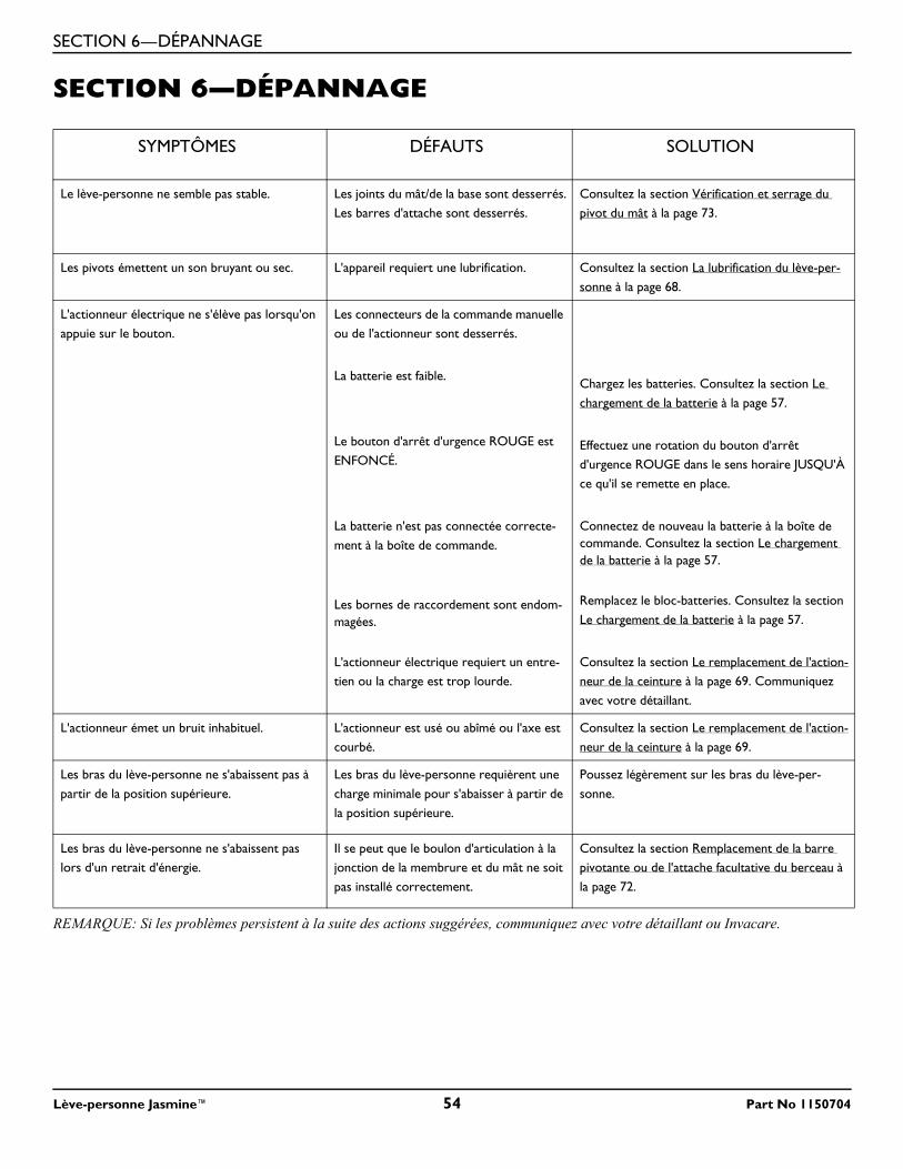
SECTION 6—DÉPANNAGE
Lève-personne Jasmine™ 54 Part No 1150704
SECTION 6—DÉPANNAGE
REMARQUE: Si les problèmes persistent à la suite des actions suggérées, communiquez avec votre détaillant ou Invacare.
SYMPTÔMES DÉFAUTS SOLUTION
Le lève-personne ne semble pas stable. Les joints du mât/de la base sont desserrés.Les barres d'attache sont desserrés.
Consultez la section Vérification et serrage du pivot du mât à la page 73.
Les pivots émettent un son bruyant ou sec. L'appareil requiert une lubrification. Consultez la section La lubrification du lève-per-sonne à la page 68.
L'actionneur électrique ne s'élève pas lorsqu'on appuie sur le bouton.
Les connecteurs de la commande manuelle ou de l'actionneur sont desserrés.
La batterie est faible.
Le bouton d'arrêt d'urgence ROUGE est ENFONCÉ.
La batterie n'est pas connectée correcte-ment à la boîte de commande.
Les bornes de raccordement sont endom-magées.
L'actionneur électrique requiert un entre-tien ou la charge est trop lourde.
Chargez les batteries. Consultez la section Le chargement de la batterie à la page 57.
Effectuez une rotation du bouton d'arrêt d'urgence ROUGE dans le sens horaire JUSQU'À ce qu'il se remette en place.
Connectez de nouveau la batterie à la boîte de commande. Consultez la section Le chargement de la batterie à la page 57.
Remplacez le bloc-batteries. Consultez la section Le chargement de la batterie à la page 57.
Consultez la section Le remplacement de l'action-neur de la ceinture à la page 69. Communiquez avec votre détaillant.
L'actionneur émet un bruit inhabituel. L'actionneur est usé ou abîmé ou l'axe est courbé.
Consultez la section Le remplacement de l'action-neur de la ceinture à la page 69.
Les bras du lève-personne ne s'abaissent pas à partir de la position supérieure.
Les bras du lève-personne requièrent une charge minimale pour s'abaisser à partir de la position supérieure.
Poussez légèrement sur les bras du lève-per-sonne.
Les bras du lève-personne ne s'abaissent pas lors d'un retrait d'énergie.
Il se peut que le boulon d'articulation à la jonction de la membrure et du mât ne soit pas installé correctement.
Consultez la section Remplacement de la barre pivotante ou de l'attache facultative du berceau à la page 72.
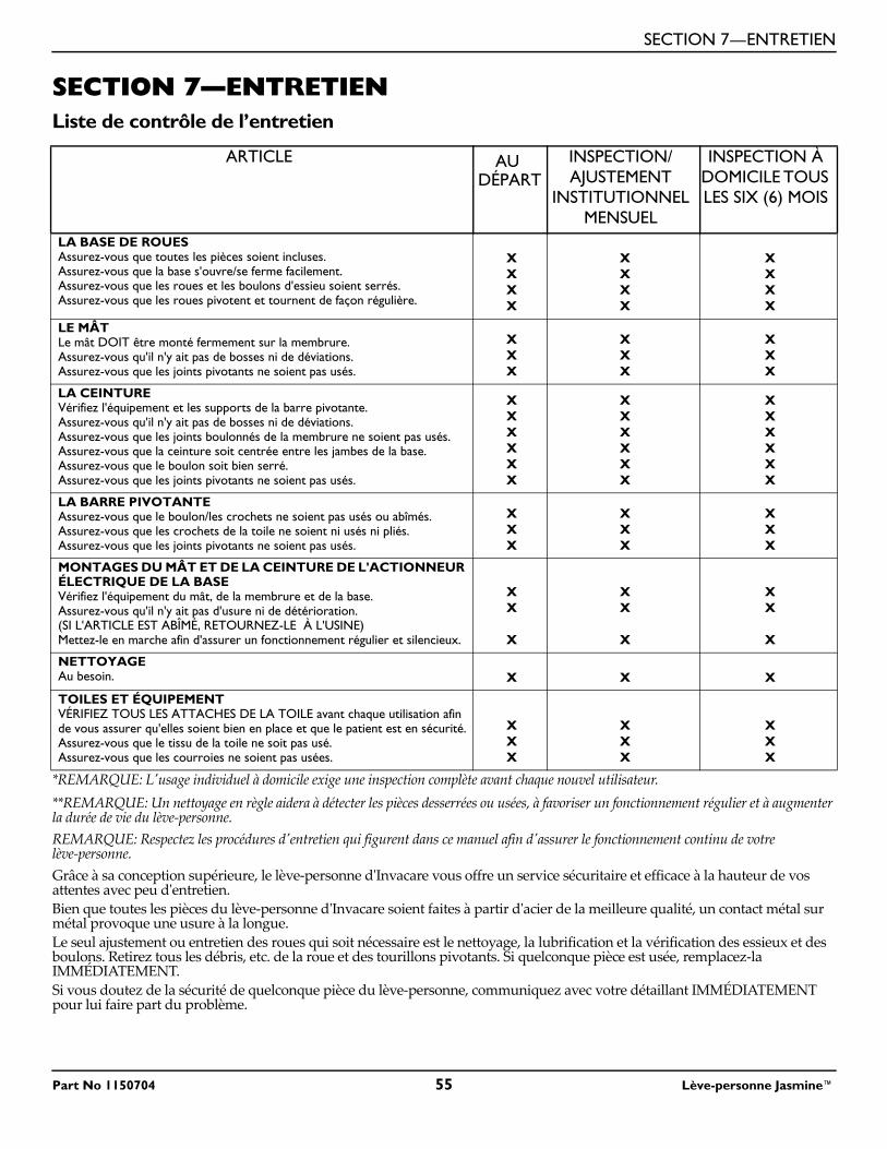
SECTION 7—ENTRETIEN
SECTION 7—ENTRETIENListe de contrôle de l’entretien
*REMARQUE: L'usage individuel à domicile exige une inspection complète avant chaque nouvel utilisateur.**REMARQUE: Un nettoyage en règle aidera à détecter les pièces desserrées ou usées, à favoriser un fonctionnement régulier et à augmenter la durée de vie du lève-personne.REMARQUE: Respectez les procédures d'entretien qui figurent dans ce manuel afin d'assurer le fonctionnement continu de votre lève-personne.Grâce à sa conception supérieure, le lève-personne d'Invacare vous offre un service sécuritaire et efficace à la hauteur de vos attentes avec peu d'entretien.Bien que toutes les pièces du lève-personne d'Invacare soient faites à partir d'acier de la meilleure qualité, un contact métal sur métal provoque une usure à la longue.Le seul ajustement ou entretien des roues qui soit nécessaire est le nettoyage, la lubrification et la vérification des essieux et des boulons. Retirez tous les débris, etc. de la roue et des tourillons pivotants. Si quelconque pièce est usée, remplacez-la IMMÉDIATEMENT. Si vous doutez de la sécurité de quelconque pièce du lève-personne, communiquez avec votre détaillant IMMÉDIATEMENT pour lui faire part du problème.
ARTICLE AU DÉPART
INSPECTION/AJUSTEMENT
INSTITUTIONNEL MENSUEL
INSPECTION À DOMICILE TOUS LES SIX (6) MOIS
LA BASE DE ROUESAssurez-vous que toutes les pièces soient incluses.Assurez-vous que la base s'ouvre/se ferme facilement.Assurez-vous que les roues et les boulons d'essieu soient serrés.Assurez-vous que les roues pivotent et tournent de façon régulière.
XXXX
XXXX
XXXX
LE MÂTLe mât DOIT être monté fermement sur la membrure.Assurez-vous qu'il n'y ait pas de bosses ni de déviations.Assurez-vous que les joints pivotants ne soient pas usés.
XXX
XXX
XXX
LA CEINTUREVérifiez l'équipement et les supports de la barre pivotante.Assurez-vous qu'il n'y ait pas de bosses ni de déviations.Assurez-vous que les joints boulonnés de la membrure ne soient pas usés.Assurez-vous que la ceinture soit centrée entre les jambes de la base.Assurez-vous que le boulon soit bien serré.Assurez-vous que les joints pivotants ne soient pas usés.
XXXXXX
XXXXXX
XXXXXX
LA BARRE PIVOTANTE Assurez-vous que le boulon/les crochets ne soient pas usés ou abîmés.Assurez-vous que les crochets de la toile ne soient ni usés ni pliés.Assurez-vous que les joints pivotants ne soient pas usés.
XXX
XXX
XXX
MONTAGES DU MÂT ET DE LA CEINTURE DE L'ACTIONNEUR ÉLECTRIQUE DE LA BASEVérifiez l'équipement du mât, de la membrure et de la base.Assurez-vous qu'il n'y ait pas d'usure ni de détérioration.(SI L'ARTICLE EST ABÎMÉ, RETOURNEZ-LE À L'USINE)Mettez-le en marche afin d'assurer un fonctionnement régulier et silencieux.
XX
X
XX
X
XX
X
NETTOYAGEAu besoin. X X X
TOILES ET ÉQUIPEMENTVÉRIFIEZ TOUS LES ATTACHES DE LA TOILE avant chaque utilisation afin de vous assurer qu'elles soient bien en place et que le patient est en sécurité.Assurez-vous que le tissu de la toile ne soit pas usé.Assurez-vous que les courroies ne soient pas usées.
XXX
XXX
XXX
Part No 1150704 55 Lève-personne Jasmine™
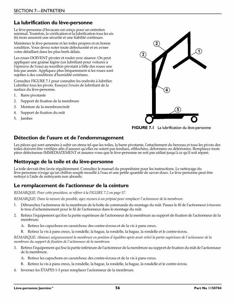
SECTION 7—ENTRETIEN
La lubrification du lève-personneLe lève-personne d'Invacare est conçu pour un entretien minimal. Toutefois, la vérification et la lubrification tous les six (6) mois assurent une sécurité et une fiabilité continues.Maintenez le lève-personne et les toiles propres et en bonne condition. Vous devez noter toute défectuosité et en aviser votre détaillant dans les plus brefs délais.Les roues DOIVENT pivoter et rouler avec aisance. On peut appliquer une graisse légère (un lubrifiant pour voitures à l'épreuve de l'eau) au tourillon pivotant à bille des roues une fois par année. Appliquez plus fréquemment si les roues sont sujettes à des conditions d'humidité extrêmes.Consultez FIGURE 7.1 pour connaître les endroits à lubrifier. Lubrifiez tous les pivots. Essuyez l'excès de lubrifiant de la surface du lève-personne.1. Barre pivotante2. Support de fixation de la membrure3. Monture de la membrure/mât4. Support de fixation du mât5. Jambes
FIGURE 7.1 La lubrification du lève-personne
Détection de l'usure et de l'endommagementLes pièces qui sont amenées à subir un stress tel que les toiles, la barre pivotante, l'attachement du berceau et tous les pivots des toiles doivent être vérifiées afin d'assurer qu'elles ne soient pas fendues, effilochées, déformées ou détériorées. Remplacez toute pièce défectueuse IMMÉDIATEMENT et assurez-vous que le lève-personne ne soit pas utilisé jusqu'à ce qu'il soit réparé.
Nettoyage de la toile et du lève-personneLa toile devrait être lavée régulièrement. Consultez le manuel du propriétaire pour les instructions. Le nettoyage du lève-personne n'exige qu'un chiffon souple mouillé à l'eau et une petite quantité de savon doux. Le lève-personne peut être nettoyé à l'aide de nettoyants non abrasifs.
Le remplacement de l'actionneur de la ceintureREMARQUE: Pour cette procédure, se référer à la FIGURE 7.2 on page 57.REMARQUE: Dans la mesure du possible, ayez recours à un préposé pour remplacer l'actionneur de la membrure.1. Débranchez l'actionneur de la membrure de la boîte de commande du montage du mât. Passez le fil de l'actionneur à travers
le trou d'acheminement pour le fil de l'actionneur dans le montage du mât.2. Retirez l'équipement qui fixe la partie supérieure de l'actionneur de la membrure au support de fixation de l'actionneur de la
membrure.A. Retirez les capuchons en caoutchouc des contre-écrous et de la vis à pans creux.B. Retirez la vis à pans creux, la rondelle, la bague, la rondelle, la bague, la rondelle et le contre-écrou.
REMARQUE: Abaissez soigneusement la membrure en position d'équilibre après avoir retiré la partie supérieure de l'actionneur de la membrure du support de fixation de l'actionneur de la membrure.3. Retirez l'équipement qui fixe la partie inférieure de l'actionneur de la membrure au support de fixation du mât de l'actionnaur
de la membrure.A. Retirez les capuchons en caoutchouc des contre-écrous et de la vis à pans creux.B. Retirez la vis à pans creux, la rondelle, la bague, la rondelle, la bague, la rondelle et le contre-écrou.
4. Inversez les ÉTAPES 1-3 pour remplacer l'actionneur de la membrure.
5
Lève-personne Jasmine™ 56 Part No 1150704
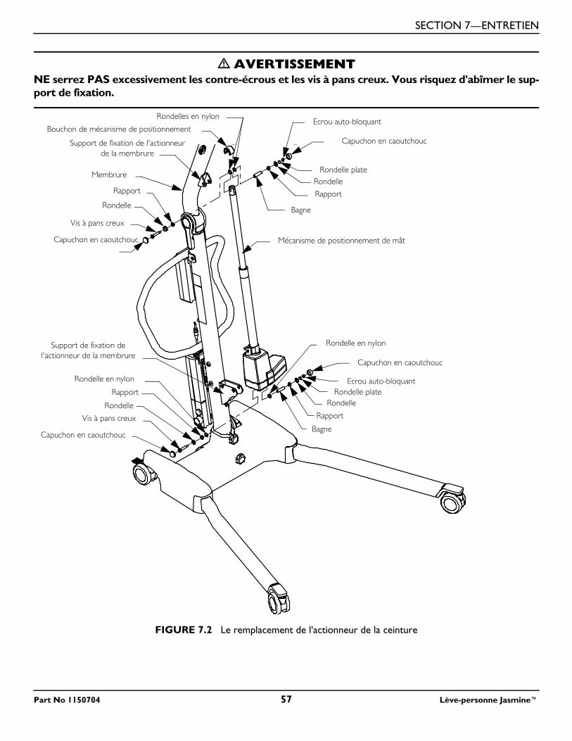
SECTION 7—ENTRETIEN
� AVERTISSEMENTNE serrez PAS excessivement les contre-écrous et les vis à pans creux. Vous risquez d'abîmer le sup-port de fixation.
FIGURE 7.2 Le remplacement de l'actionneur de la ceinture
Membrure
Capuchon en caoutchouc
Mécanisme de positionnement de mât
Vis à pans creuxBagne
Rondelle
Rondelle plateEcrou auto-bloquant
Capuchon en caoutchouc
Rapport
Ecrou auto-bloquant
Capuchon en caoutchouc
Rondelle plate
Rapport
Rondelle
Capuchon en caoutchouc
Vis à pans creux
Rapport
Bagne
Support de fixation de l'actionneur de la membrure
Support de fixation de l'actionneur de la membrure
Rondelle
Rondelle
Rondelles en nylon
Bouchon de mécanisme de positionnement
Rondelle en nylon
Rapport
Rondelle en nylon
Part No 1150704 57 Lève-personne Jasmine™
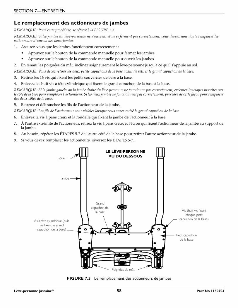
SECTION 7—ENTRETIEN
Le remplacement des actionneurs de jambesREMARQUE: Pour cette procédure, se référer à la FIGURE 7.3.REMARQUE: Si les jambes du lève-personne ne s'ouvrent et ne se ferment pas correctement, vous devrez sans doute remplacer les actionneurs d'une ou des deux jambes.1. Assurez-vous que les jambes fonctionnent correctement :
• Appuyez sur le bouton de la commande manuelle pour fermer les jambes.• Appuyez sur le bouton de la commande manuelle pour ouvrir les jambes.
2. En tenant les poignées du mât, inclinez soigneusement le lève-personne jusqu'à ce qu'il s'appuie au sol.REMARQUE: Vous devez retirer les deux petits capuchons de la base avant de retirer le grand capuchon de la base.3. Retirez les 16 vis qui fixent les petits couvercles de base à la base.4. Enlevez les huit vis à tête cylindrique qui fixent le grand capuchon de la base à la base.REMARQUE: Si la jambe gauche ou la jambe droite du lève-personne ne fonctionne pas correctement, exécutez les étapes inscrites sur le côté de la base pour remplacer l'actionneur. Si les deux jambes ne fonctionnent pas correctement, procédez de cette façon pour remplacer des deux côtés de la base.5. Repérez et débranchez les fils de l'actionneur de la jambe. REMARQUE: Les fils de l'actionneur sont visibles lorsque vous aurez retiré le grand capuchon de la base.6. Enlevez la vis à pans creux et la rondelle qui fixent la jambe de l'actionneur à la base.7. À l'autre extrémité de l'actionneur, retirez la vis à pans creux et l'écrou qui fixent l'actionneur de la jambe au support de
la jambe.8. Au besoin, répétez les ÉTAPES 5-7 de l'autre côté de la base pour retirer l'autre actionneur de la jambe.9. Si vous devez remplacer les actionneurs, inversez les ÉTAPES 5-7.
FIGURE 7.3 Le remplacement des actionneurs de jambes
Petit capuchon de la base
Poignées du mât
LE LÈVE-PERSONNE VU DU DESSOUS
Grand capuchon de
la base Vis (huit vis fixent chaque petit
capuchon de la base)Vis à tête cylindrique (huit vis fixent le grand
capuchon de la base)
Jambe
Roue
Lève-personne Jasmine™ 58 Part No 1150704
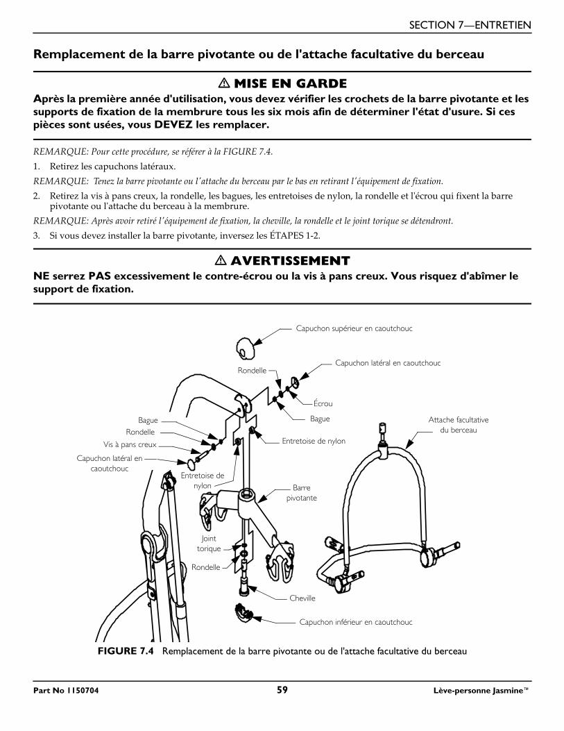
SECTION 7—ENTRETIEN
Remplacement de la barre pivotante ou de l'attache facultative du berceau
� MISE EN GARDEAprès la première année d'utilisation, vous devez vérifier les crochets de la barre pivotante et les supports de fixation de la membrure tous les six mois afin de déterminer l'état d'usure. Si ces pièces sont usées, vous DEVEZ les remplacer.
REMARQUE: Pour cette procédure, se référer à la FIGURE 7.4.1. Retirez les capuchons latéraux.REMARQUE: Tenez la barre pivotante ou l'attache du berceau par le bas en retirant l'équipement de fixation.2. Retirez la vis à pans creux, la rondelle, les bagues, les entretoises de nylon, la rondelle et l'écrou qui fixent la barre
pivotante ou l'attache du berceau à la membrure.REMARQUE: Après avoir retiré l'équipement de fixation, la cheville, la rondelle et le joint torique se détendront.3. Si vous devez installer la barre pivotante, inversez les ÉTAPES 1-2.
� AVERTISSEMENTNE serrez PAS excessivement le contre-écrou ou la vis à pans creux. Vous risquez d'abîmer le support de fixation.
FIGURE 7.4 Remplacement de la barre pivotante ou de l'attache facultative du berceau
Capuchon supérieur en caoutchouc
Capuchon latéral en caoutchouc
Écrou
Rondelle
Entretoise de nylon
Entretoise de nylon
Capuchon latéral en caoutchouc
Vis à pans creux
RondelleBague
Barre pivotante
Capuchon inférieur en caoutchouc
Cheville
Joint torique
Rondelle
Attache facultative du berceau
Bague
Part No 1150704 59 Lève-personne Jasmine™
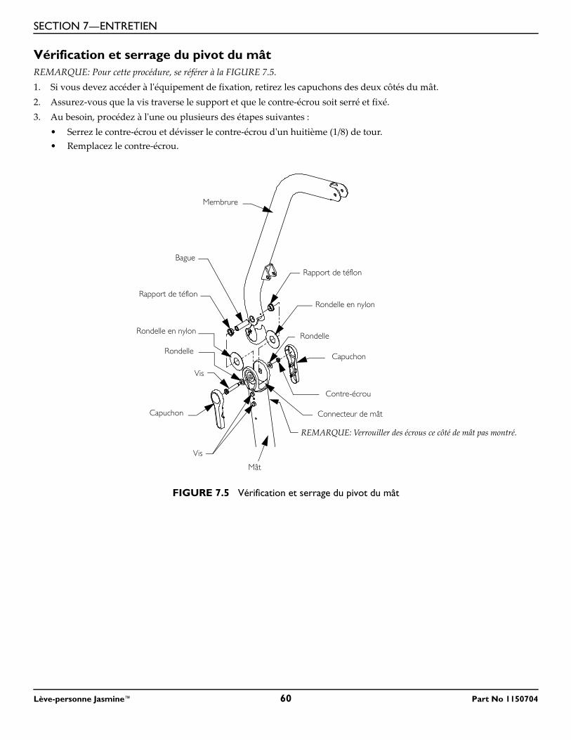
SECTION 7—ENTRETIEN
Vérification et serrage du pivot du mâtREMARQUE: Pour cette procédure, se référer à la FIGURE 7.5.1. Si vous devez accéder à l'équipement de fixation, retirez les capuchons des deux côtés du mât.2. Assurez-vous que la vis traverse le support et que le contre-écrou soit serré et fixé.3. Au besoin, procédez à l'une ou plusieurs des étapes suivantes :
• Serrez le contre-écrou et dévisser le contre-écrou d'un huitième (1/8) de tour.• Remplacez le contre-écrou.
FIGURE 7.5 Vérification et serrage du pivot du mât
Membrure
Rondelle
Capuchon
Connecteur de mât
Contre-écrou
Bague
Rondelle
Vis
Capuchon
REMARQUE: Verrouiller des écrous ce côté de mât pas montré.
Mât
Vis
Rondelle en nylonRapport de téflon
Rapport de téflon
Rondelle en nylon
Lève-personne Jasmine™ 60 Part No 1150704
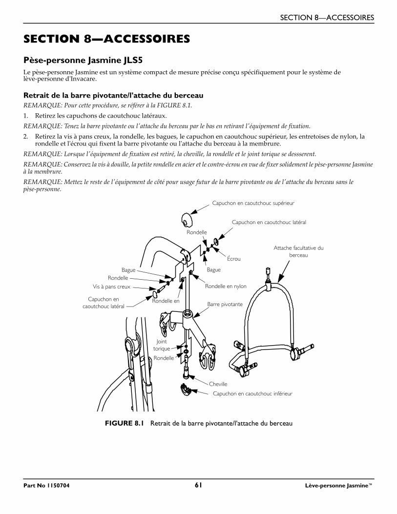
SECTION 8—ACCESSOIRES
SECTION 8—ACCESSOIRES
Pèse-personne Jasmine JLS5Le pèse-personne Jasmine est un système compact de mesure précise conçu spécifiquement pour le système de lève-personne d'Invacare.
Retrait de la barre pivotante/l'attache du berceauREMARQUE: Pour cette procédure, se référer à la FIGURE 8.1.1. Retirez les capuchons de caoutchouc latéraux.REMARQUE: Tenez la barre pivotante ou l'attache du berceau par le bas en retirant l'équipement de fixation.2. Retirez la vis à pans creux, la rondelle, les bagues, le capuchon en caoutchouc supérieur, les entretoises de nylon, la
rondelle et l'écrou qui fixent la barre pivotante ou l'attache du berceau à la membrure.REMARQUE: Lorsque l'équipement de fixation est retiré, la cheville, la rondelle et le joint torique se dessserent.REMARQUE: Conservez la vis à douille, la petite rondelle en acier et le contre-écrou en vue de fixer solidement le pèse-personne Jasmine à la membrure.REMARQUE: Mettez le reste de l'équipement de côté pour usage futur de la barre pivotante ou de l'attache du berceau sans le pèse-personne.
FIGURE 8.1 Retrait de la barre pivotante/l'attache du berceau
Capuchon en caoutchouc supérieur
Capuchon en caoutchouc latéral
Écrou
Rondelle
Rondelle en nylon
Rondelle en Capuchon en caoutchouc latéral
Vis à pans creux
RondelleBague
Barre pivotante
Capuchon en caoutchouc inférieur
Cheville
Joint torique
Rondelle
Attache facultative du berceau
Bague
Part No 1150704 61 Lève-personne Jasmine™
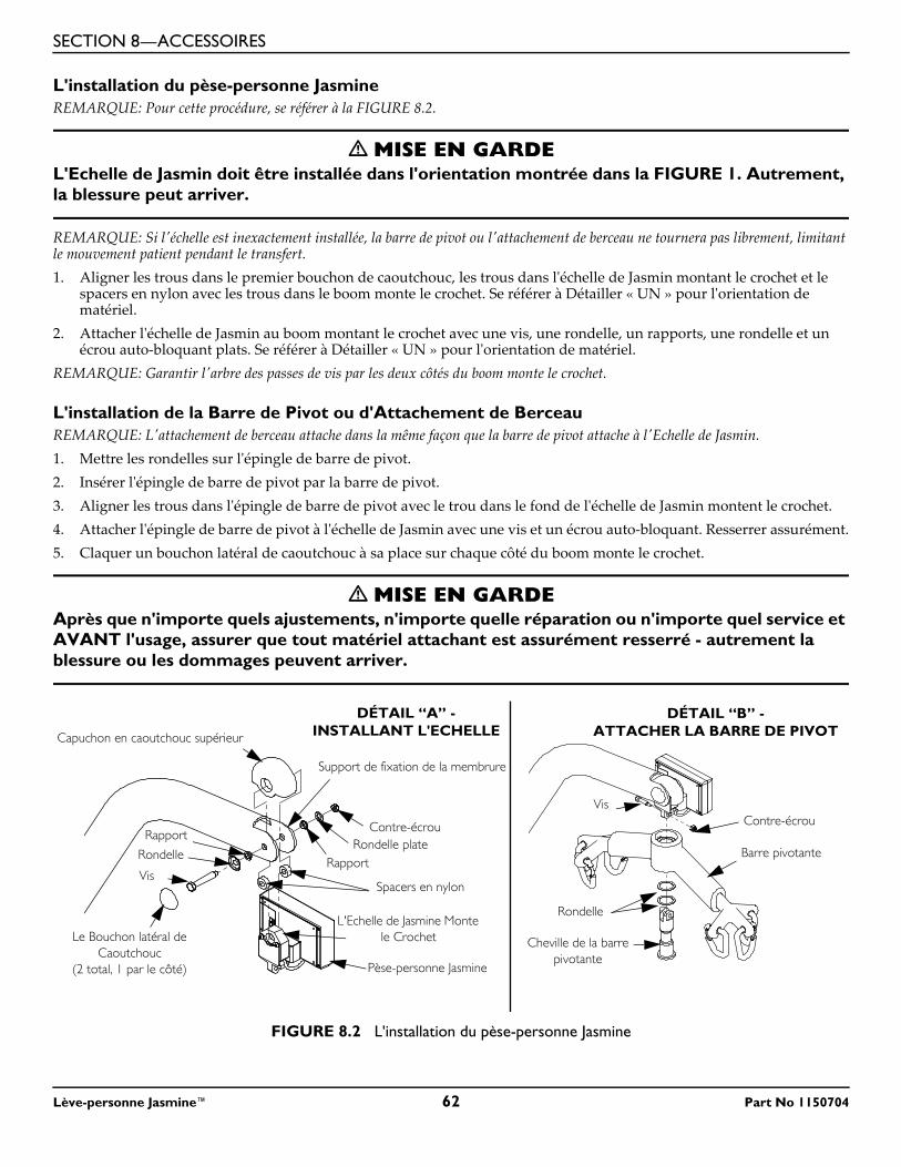
SECTION 8—ACCESSOIRES
L'installation du pèse-personne JasmineREMARQUE: Pour cette procédure, se référer à la FIGURE 8.2.
� MISE EN GARDEL'Echelle de Jasmin doit être installée dans l'orientation montrée dans la FIGURE 1. Autrement, la blessure peut arriver.
REMARQUE: Si l'échelle est inexactement installée, la barre de pivot ou l'attachement de berceau ne tournera pas librement, limitant le mouvement patient pendant le transfert.1. Aligner les trous dans le premier bouchon de caoutchouc, les trous dans l'échelle de Jasmin montant le crochet et le
spacers en nylon avec les trous dans le boom monte le crochet. Se référer à Détailler « UN » pour l'orientation de matériel.
2. Attacher l'échelle de Jasmin au boom montant le crochet avec une vis, une rondelle, un rapports, une rondelle et un écrou auto-bloquant plats. Se référer à Détailler « UN » pour l'orientation de matériel.
REMARQUE: Garantir l'arbre des passes de vis par les deux côtés du boom monte le crochet.
L'installation de la Barre de Pivot ou d'Attachement de BerceauREMARQUE: L'attachement de berceau attache dans la même façon que la barre de pivot attache à l'Echelle de Jasmin.1. Mettre les rondelles sur l'épingle de barre de pivot.2. Insérer l'épingle de barre de pivot par la barre de pivot.3. Aligner les trous dans l'épingle de barre de pivot avec le trou dans le fond de l'échelle de Jasmin montent le crochet.4. Attacher l'épingle de barre de pivot à l'échelle de Jasmin avec une vis et un écrou auto-bloquant. Resserrer assurément.5. Claquer un bouchon latéral de caoutchouc à sa place sur chaque côté du boom monte le crochet.
� MISE EN GARDEAprès que n'importe quels ajustements, n'importe quelle réparation ou n'importe quel service et AVANT l'usage, assurer que tout matériel attachant est assurément resserré - autrement la blessure ou les dommages peuvent arriver.
FIGURE 8.2 L'installation du pèse-personne Jasmine
Contre-écrou
Barre pivotante
Rondelle
Cheville de la barre pivotante
Pèse-personne Jasmine
Contre-écrou
Spacers en nylon
Rondelle plate
Capuchon en caoutchouc supérieur
Rapport
Le Bouchon latéral de Caoutchouc
(2 total, 1 par le côté)
Support de fixation de la membrure
Vis
Rapport
Rondelle
Vis
DÉTAIL “B” -ATTACHER LA BARRE DE PIVOT
DÉTAIL “A” - INSTALLANT L'ECHELLE
L'Echelle de Jasmine Monte le Crochet
Lève-personne Jasmine™ 62 Part No 1150704
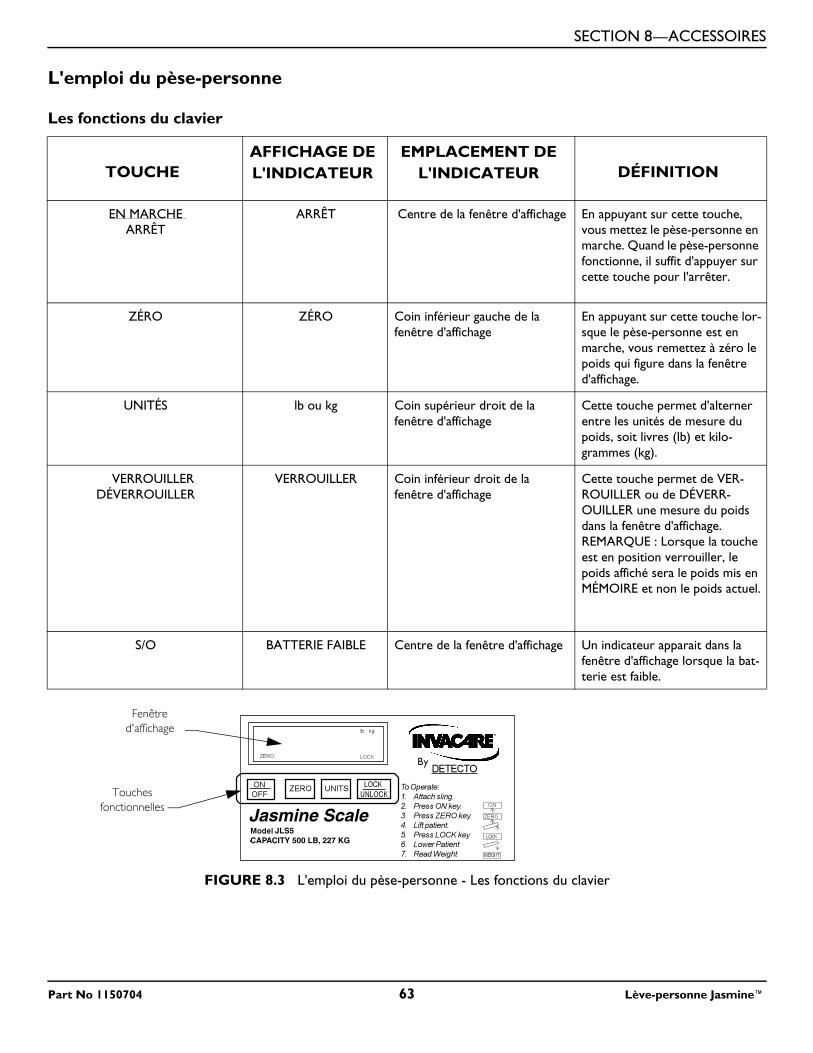
SECTION 8—ACCESSOIRES
L'emploi du pèse-personne
Les fonctions du clavier
FIGURE 8.3 L'emploi du pèse-personne - Les fonctions du clavier
TOUCHEAFFICHAGE DE L'INDICATEUR
EMPLACEMENT DE L'INDICATEUR DÉFINITION
EN MARCHE ARRÊT
ARRÊT Centre de la fenêtre d'affichage En appuyant sur cette touche, vous mettez le pèse-personne en marche. Quand le pèse-personne fonctionne, il suffit d'appuyer sur cette touche pour l'arrêter.
ZÉRO ZÉRO Coin inférieur gauche de la fenêtre d'affichage
En appuyant sur cette touche lor-sque le pèse-personne est en marche, vous remettez à zéro le poids qui figure dans la fenêtre d'affichage.
UNITÉS lb ou kg Coin supérieur droit de la fenêtre d'affichage
Cette touche permet d'alterner entre les unités de mesure du poids, soit livres (lb) et kilo-grammes (kg).
VERROUILLER DÉVERROUILLER
VERROUILLER Coin inférieur droit de la fenêtre d'affichage
Cette touche permet de VER-ROUILLER ou de DÉVERR-OUILLER une mesure du poids dans la fenêtre d'affichage.REMARQUE : Lorsque la touche est en position verrouiller, le poids affiché sera le poids mis en MÉMOIRE et non le poids actuel.
S/O BATTERIE FAIBLE Centre de la fenêtre d'affichage Un indicateur apparait dans la fenêtre d'affichage lorsque la bat-terie est faible.
Jasmine ScaleJLS5
CAPACITY 500 LB, 227 KG
Touches fonctionnelles
Fenêtre d'affichage
Part No 1150704 63 Lève-personne Jasmine™
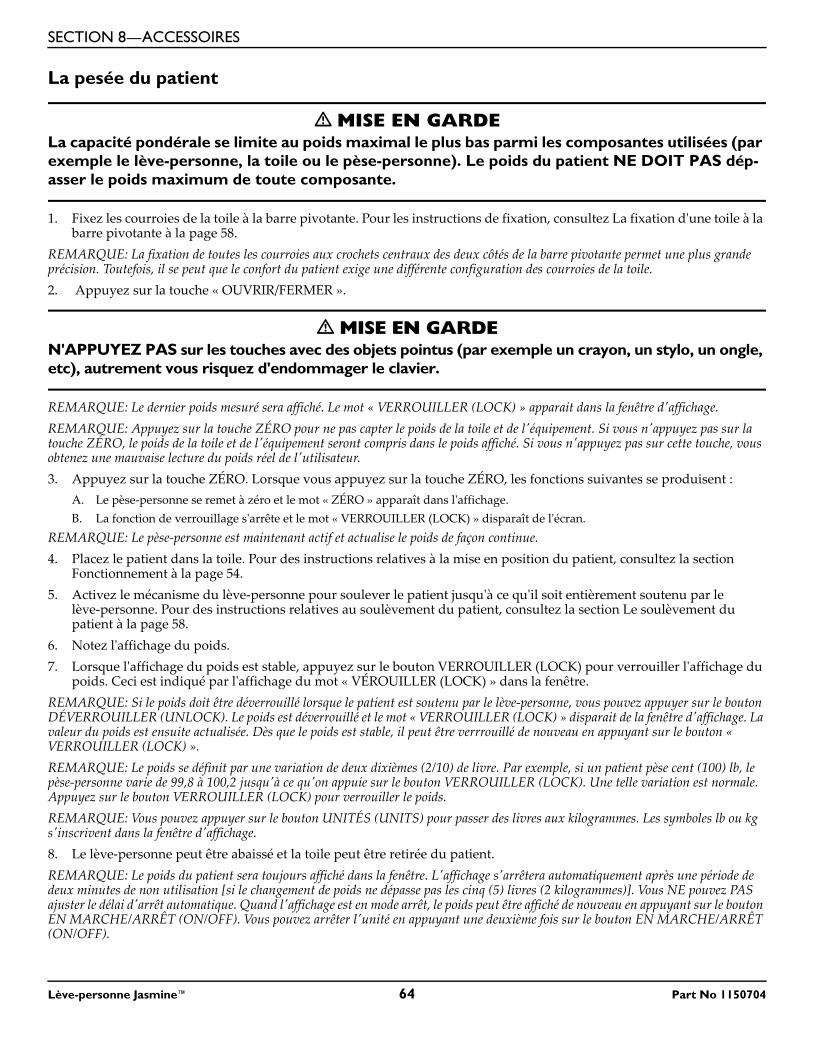
SECTION 8—ACCESSOIRES
La pesée du patient
� MISE EN GARDELa capacité pondérale se limite au poids maximal le plus bas parmi les composantes utilisées (par exemple le lève-personne, la toile ou le pèse-personne). Le poids du patient NE DOIT PAS dép-asser le poids maximum de toute composante.
1. Fixez les courroies de la toile à la barre pivotante. Pour les instructions de fixation, consultez La fixation d'une toile à la barre pivotante à la page 58.
REMARQUE: La fixation de toutes les courroies aux crochets centraux des deux côtés de la barre pivotante permet une plus grande précision. Toutefois, il se peut que le confort du patient exige une différente configuration des courroies de la toile.2. Appuyez sur la touche « OUVRIR/FERMER ».
� MISE EN GARDEN'APPUYEZ PAS sur les touches avec des objets pointus (par exemple un crayon, un stylo, un ongle, etc), autrement vous risquez d'endommager le clavier.
REMARQUE: Le dernier poids mesuré sera affiché. Le mot « VERROUILLER (LOCK) » apparait dans la fenêtre d'affichage.REMARQUE: Appuyez sur la touche ZÉRO pour ne pas capter le poids de la toile et de l'équipement. Si vous n'appuyez pas sur la touche ZÉRO, le poids de la toile et de l'équipement seront compris dans le poids affiché. Si vous n'appuyez pas sur cette touche, vous obtenez une mauvaise lecture du poids réel de l'utilisateur.3. Appuyez sur la touche ZÉRO. Lorsque vous appuyez sur la touche ZÉRO, les fonctions suivantes se produisent :
A. Le pèse-personne se remet à zéro et le mot « ZÉRO » apparaît dans l'affichage.B. La fonction de verrouillage s'arrête et le mot « VERROUILLER (LOCK) » disparaît de l'écran.
REMARQUE: Le pèse-personne est maintenant actif et actualise le poids de façon continue.4. Placez le patient dans la toile. Pour des instructions relatives à la mise en position du patient, consultez la section
Fonctionnement à la page 54.5. Activez le mécanisme du lève-personne pour soulever le patient jusqu'à ce qu'il soit entièrement soutenu par le
lève-personne. Pour des instructions relatives au soulèvement du patient, consultez la section Le soulèvement du patient à la page 58.
6. Notez l'affichage du poids.7. Lorsque l'affichage du poids est stable, appuyez sur le bouton VERROUILLER (LOCK) pour verrouiller l'affichage du
poids. Ceci est indiqué par l'affichage du mot « VÉROUILLER (LOCK) » dans la fenêtre. REMARQUE: Si le poids doit être déverrouillé lorsque le patient est soutenu par le lève-personne, vous pouvez appuyer sur le bouton DÉVERROUILLER (UNLOCK). Le poids est déverrouillé et le mot « VERROUILLER (LOCK) » disparait de la fenêtre d'affichage. La valeur du poids est ensuite actualisée. Dès que le poids est stable, il peut être verrrouillé de nouveau en appuyant sur le bouton « VERROUILLER (LOCK) ».REMARQUE: Le poids se définit par une variation de deux dixièmes (2/10) de livre. Par exemple, si un patient pèse cent (100) lb, le pèse-personne varie de 99,8 à 100,2 jusqu'à ce qu'on appuie sur le bouton VERROUILLER (LOCK). Une telle variation est normale. Appuyez sur le bouton VERROUILLER (LOCK) pour verrouiller le poids.REMARQUE: Vous pouvez appuyer sur le bouton UNITÉS (UNITS) pour passer des livres aux kilogrammes. Les symboles lb ou kg s'inscrivent dans la fenêtre d'affichage.8. Le lève-personne peut être abaissé et la toile peut être retirée du patient.REMARQUE: Le poids du patient sera toujours affiché dans la fenêtre. L'affichage s'arrêtera automatiquement après une période de deux minutes de non utilisation [si le changement de poids ne dépasse pas les cinq (5) livres (2 kilogrammes)]. Vous NE pouvez PAS ajuster le délai d'arrêt automatique. Quand l'affichage est en mode arrêt, le poids peut être affiché de nouveau en appuyant sur le bouton EN MARCHE/ARRÊT (ON/OFF). Vous pouvez arrêter l'unité en appuyant une deuxième fois sur le bouton EN MARCHE/ARRÊT (ON/OFF).
Lève-personne Jasmine™ 64 Part No 1150704
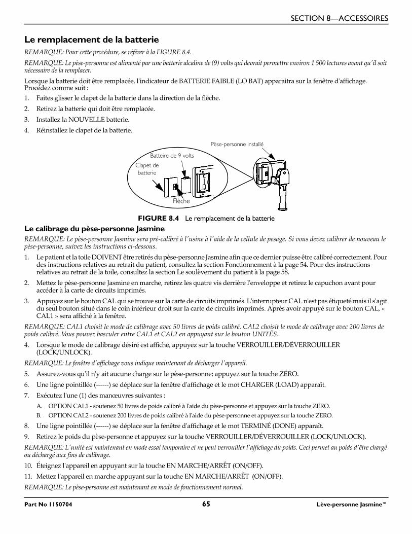
SECTION 8—ACCESSOIRES
Le remplacement de la batterieREMARQUE: Pour cette procédure, se référer à la FIGURE 8.4.REMARQUE: Le pèse-personne est alimenté par une batterie alcaline de (9) volts qui devrait permettre environ 1 500 lectures avant qu'il soit nécessaire de la remplacer.Lorsque la batterie doit être remplacée, l'indicateur de BATTERIE FAIBLE (LO BAT) apparaitra sur la fenêtre d'affichage. Procédez comme suit :1. Faites glisser le clapet de la batterie dans la direction de la flèche.2. Retirez la batterie qui doit être remplacée.3. Installez la NOUVELLE batterie.4. Réinstallez le clapet de la batterie.
FIGURE 8.4 Le remplacement de la batterieLe calibrage du pèse-personne JasmineREMARQUE: Le pèse-personne Jasmine sera pré-calibré à l'usine à l'aide de la cellule de pesage. Si vous devez calibrer de nouveau le pèse-personne, suivez les instructions ci-dessous.1. Le patient et la toile DOIVENT être retirés du pèse-personne Jasmine afin que ce dernier puisse être calibré correctement. Pour
des instructions relatives au retrait du patient, consultez la section Fonctionnement à la page 54. Pour des instructions relatives au retrait de la toile, consultez la section Le soulèvement du patient à la page 58.
2. Mettez le pèse-personne Jasmine en marche, retirez les quatre vis derrière l'enveloppe et retirez le capuchon avant pour accéder à la carte de circuits imprimés.
3. Appuyez sur le bouton CAL qui se trouve sur la carte de circuits imprimés. L'interrupteur CAL n'est pas étiqueté mais il s'agit du seul bouton situé dans le coin inférieur droit sur la carte de circuits imprimés. Après avoir appuyé sur le bouton CAL, « CAL1 » sera affiché à la fenêtre.
REMARQUE: CAL1 choisit le mode de calibrage avec 50 livres de poids calibré. CAL2 choisit le mode de calibrage avec 200 livres de poids calibré. Vous pouvez basculer entre CAL1 et CAL2 en appuyant sur le bouton UNITÉS.4. Lorsque le mode de calibrage désiré est affiché, appuyez sur la touche VERROUILLER/DÉVERROUILLER
(LOCK/UNLOCK). REMARQUE: Le fenêtre d'affichage vous indique maintenant de décharger l'appareil.5. Assurez-vous qu'il n'y ait aucune charge sur le pèse-personne; appuyez sur la touche ZÉRO.6. Une ligne pointillée (------) se déplace sur la fenêtre d'affichage et le mot CHARGER (LOAD) apparaît.7. Exécutez l'une (1) des manœuvres suivantes :
A. OPTION CAL1 - soutenez 50 livres de poids calibré à l'aide du pèse-personne et appuyez sur la touche ZERO.B. OPTION CAL2 - soutenez 200 livres de poids calibré à l'aide du pèse-personne et appuyez sur la touche ZERO.
8. Une ligne pointillée (------) se déplace sur la fenêtre d'affichage et le mot TERMINÉ (DONE) apparaît.9. Retirez le poids du pèse-personne et appuyez sur la touche VERROUILLER/DÉVERROUILLER (LOCK/UNLOCK).REMARQUE: L'unité est maintenant en mode essai temporaire et ne peut verrouiller l'affichage du poids. Ceci permet au poids d'être chargé ou déchargé aux fins de calibrage. 10. Éteignez l'appareil en appuyant sur la touche EN MARCHE/ARRÊT (ON/OFF). 11. Mettez l'appareil en marche appuyant sur la touche EN MARCHE/ARRÊT (ON/OFF).REMARQUE: Le pèse-personne est maintenant en mode de fonctionnement normal.
Clapet de batterie
Batteire de 9 volts
Pèse-personne installé
Flèche
Part No 1150704 65 Lève-personne Jasmine™
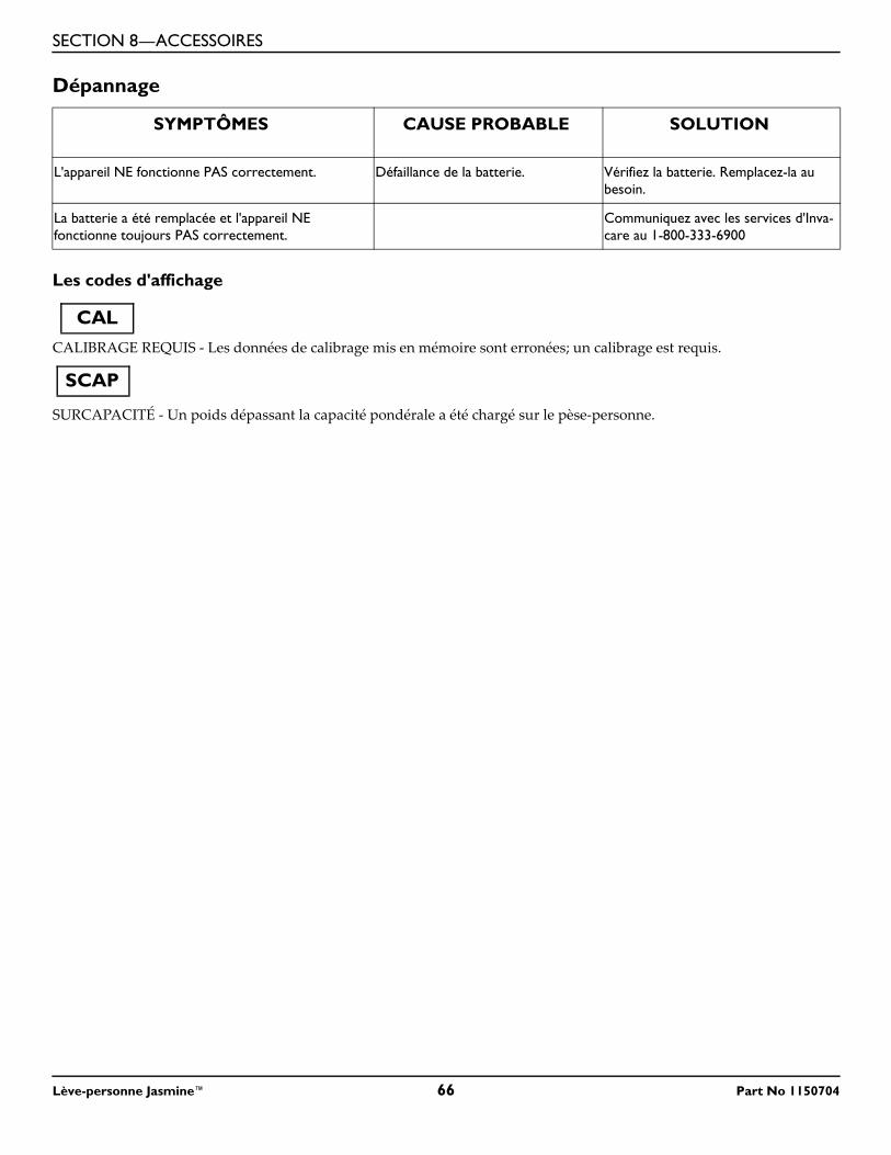
SECTION 8—ACCESSOIRES
Dépannage
Les codes d'affichage
CALIBRAGE REQUIS - Les données de calibrage mis en mémoire sont erronées; un calibrage est requis.
SURCAPACITÉ - Un poids dépassant la capacité pondérale a été chargé sur le pèse-personne.
SYMPTÔMES CAUSE PROBABLE SOLUTION
L'appareil NE fonctionne PAS correctement. Défaillance de la batterie. Vérifiez la batterie. Remplacez-la au besoin.
La batterie a été remplacée et l'appareil NE fonctionne toujours PAS correctement.
Communiquez avec les services d'Inva-care au 1-800-333-6900
CAL
SCAP
Lève-personne Jasmine™ 66 Part No 1150704

SECTION 8—ACCESSOIRES
REMARQUES
Part No 1150704 67 Lève-personne Jasmine™
Invacare Corporation www.invacare.com
USAOne Invacare WayElyria, Ohio USA44036-2125800-333-6900
Canada570 Matheson Blvd. E Unit 8Mississauga OntarioL4Z 4G4 Canada800-668-5324
©2013 Invacare Corporation. All rights reserved. Republication, duplication or modification in whole or in part is prohibited without prior written permission from Invacare. Trademarks are identified by ™ and ®. All trademarks are owned by or licensed to Invacare Corporation or its subsidiaries unless otherwise noted.
Part No 1150704 Rev D - 12/13
GARANTIE LIMITÉECette garantie est valable uniquement pour l'acheteur/utilisateur original de nos produits.
Cette garantie vous donne des droits légaux spécifiques. Vous pouvez jouir d'autres droits qui s'appliquent d'une province à l'autre.
Invacare garantit que les produits fabriqués sont libres de toutes défectuosités quant aux matériaux et à la fabrication pour une période de cinq ans en ce qui a trait au lève-personne et d'un an pour les composantes électriques et ceci, à partir de la date d'achat. Si, au cours de la période de garantie, un produit est jugé défectueux, il sera réparé ou remplacé à la discrétion d’Invacare. Cette garantie ne comprend pas la main-d’œuvre ou les frais d’expédition encourus pour le remplacement de pièces ou la réparation dudit produit. L’unique obligation d’Invacare et votre recours exclusif dans cette garantie se limitera à une telle réparation et/ou un tel remplacement.
Pour le service au titre de la garantie, communiquez avec le détaillant chez qui vous avez acheté le produit Invacare. En cas d’insatisfaction à l’égard du service au titre de la garantie, écrivez directement à Invacare à l’adresse qui figure sur la quatrième de couverture en indiquant le nom et l'adresse du détaillant, la date d'achat et la nature du défaut.
Invacare Corporation émettra une autorisation de retour avec numéro de série. L'unité ou la pièce défectueuse DOIT être retournée pour une inspection de garantie et doit renfermer son numéro de série, le cas échéant, aux fins d'identification dans les trente jours suivant la date d'autorisation du retour. NE retournez PAS de produits à notre usine sans autorisation préalable de notre part. Les envois contre remboursement (C.O.D) seront refusés ; veuillez prépayer les frais d'envoi.
LIMITES ET EXCLUSIONS : LA GARANTIE SUSMENTIONNÉE NE S'APPLIQUE PAS AUX PRODUITS DONT LE NUMÉRO DE SÉRIE A ÉTÉ RETIRÉ OU MODIFIÉ ; AUX PRODUITS QUI ONT FAIT L'OBJET DE NÉGLIGENCE OU D'ACCIDENT, D'UNE MAUVAISE UTILISATION, D'UN MAUVAIS ENTRETIEN OU D'UN MAUVAIS ENTREPOSAGE ; AUX PRODUITS MODIFIÉS SANS L'ACCORD ÉCRIT D'INVACARE, Y COMPRIS, SANS S'Y LIMITER, LA MODIFICATION AU MOYEN DE PIÈCES OU DE RALLONGES NON AUTORISÉES ; AUX PRODUITS ENDOMMAGÉS À LA SUITE DE RÉPARATIONS DE TOUTES COMPOSANTES SANS L'ACCORD SPÉCIFIQUE D'INVACARE ; AUX PRODUITS ENDOMMAGÉS DANS DES CIRCONSTANCES HORS DU CONTRÔLE D'INVACARE. UNE TELLE ÉVALUATION NE SERA FAITE QUE PAR INVACARE. CETTE GARANTIE NE S'APPLIQUE PAS À DES PROBLÈMES DUS À L'USURE NORMALE OU AU NON-RESPECT DES INSTRUCTIONS CONTENUES DANS CE MANUEL.
LA GARANTIE SUSMENTIONNÉE EST EXCLUSIVE ET REMPLACE TOUTE AUTRE GARANTIE. LES GARANTIES IMPLICITES, S'IL Y A LIEU, COMPRENNENT LES GARANTIES IMPLICITES DE QUALITÉ MARCHANDE ET D’APTITUDE À UN USAGE PARTICULIER, NE S'ÉTENDRA PAS AU-DELÀ DE LA DURÉE DE LA GARANTIE MENTIONNÉE DANS LA PRÉSENTE ET L’UNIQUE RECOURS EN CAS DE VIOLATION DE QUELCONQUE GARANTIE SERA LIMITÉ À LA RÉPARATION OU AU REMPLACEMENT DU PRODUIT DÉFECTUEUX CONFORMÉMENT AUX CONDITIONS ÉNONCÉES DANS LA PRÉSENTE. INVACARE N'EST PAS RESPONSABLE DES DOMMAGES INDIRECTS OU ACCESSOIRES, QUELS QU’ILS SOIENT.
CERTAINS ÉTATS/PROVINCES NE PERMETTENT PAS D'EXCLUSION OU DE LIMITATION DES DOMMAGES INDIRECTS OU ACCESSOIRES OU DES LIMITATIONS SUR LA DURÉE DE VIE D'UNE GARANTIE RESTREINTE ; AINSI, LES EXCLUSIONS ET LIMITATIONS MENTIONNÉES CI-DESSUS PEUVENT NE PAS S'APPLIQUER DANS VOTRE CAS. CETTE GARANTIE SERA ÉTENDUE POUR RESPECTER LES LOIS ET RÈGLEMENTS PROVINCIAUX/D'ÉTAT.
Top Related