


Languages
Pages
Legal

©2010 IWAKI CO., LTD.
Thank you for choosing our product.
Please read through this instruction manual before use.
This instruction manual describes important precautions and instruc-tions for the product. Always keep it on hand for quick reference.
Instruction manual
IX series
Safety instructionsO
verviewInstallation
Operation
Maintenance
Specification
2
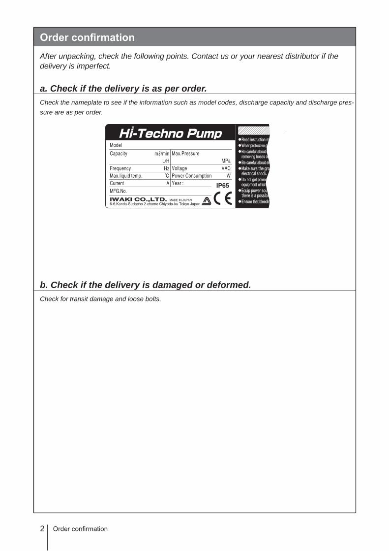
Order confirmationAfter unpacking, check the following points. Contact us or your nearest distributor if the delivery is imperfect.
a. Check if the delivery is as per order.Check the nameplate to see if the information such as model codes, discharge capacity and discharge pres-sure are as per order.
b. Check if the delivery is damaged or deformed.Check for transit damage and loose bolts.
Order confirmation

3Contents
ContentsOrder confirmation ..........................................................................................................................................2
Safety instructions .................................................................... 6Warning ..........................................................................................................................................................7Caution ...........................................................................................................................................................8Precautions for use .................................................................................................................................... 10
Overview ...................................................................................12Introduction ................................................................................................................................................. 12
Pump structure & Operating principle ...................................................................................................... 12
Features ................................................................................................................................................... 13
Operational functions ................................................................................................................................. 13Manual mode ........................................................................................................................................... 13
EXT mode ................................................................................................................................................ 14
Analogue control ................................................................................................................................. 14
Pulse control ....................................................................................................................................... 14
Batch control ....................................................................................................................................... 15
Interval batch control ........................................................................................................................... 15
AUX function ....................................................................................................................................... 16
Priming function .................................................................................................................................. 16
STOP function ..................................................................................................................................... 17
Pre-STOP function .............................................................................................................................. 17
Protective functions .................................................................................................................................. 18
Interlock function ................................................................................................................................. 18
Diaphragm rupture detection .............................................................................................................. 18
Pressure overload detection ............................................................................................................... 18
Output function .................................................................................................................................... 19
Other functions ......................................................................................................................................... 19
Suction speed setting .......................................................................................................................... 19
Diaphragm position adjustment .......................................................................................................... 19
Anti chattering programming ............................................................................................................... 19
Flow unit setting .................................................................................................................................. 19
Language setting ................................................................................................................................ 19
Keypad lock ......................................................................................................................................... 19
Default ................................................................................................................................................. 19
Part names ...................................................................................................................................................20Pump ........................................................................................................................................................20
Operational panel ..................................................................................................................................... 21
Basic displays & Pump states .............................................................................................................22
Identification codes ....................................................................................................................................23Pump ........................................................................................................................................................23

4 Contents
Installation .............................................................................. 24Pump mounting ...........................................................................................................................................24
Pipework ......................................................................................................................................................25
Piping layout ........................................................................................................................................25
Drain port (Vent hole) .................................................................................................................................26
Wiring ...........................................................................................................................................................27
End terminals ........................................................................................................................................... 27
Power voltage/Earthing ............................................................................................................................28
Signal wire connection .............................................................................................................................29
Input signal ..........................................................................................................................................30
STOP signal ........................................................................................................................................30
AUX signal........................................................................................................................................... 31
Output signal ....................................................................................................................................... 31
Operation ..................................................................................32Before operation .........................................................................................................................................32
Points to be checked ................................................................................................................................32
Retightening of pump head fixing bolts .................................................................................................... 32
Commissioning .........................................................................................................................................33
Before a long period of stoppage (One month or more) ..........................................................................33
Perform a calibration ..................................................................................................................................34
Calibration process ..................................................................................................................................35
Operation programming ............................................................................................................................. 37
Programming flow ....................................................................................................................................38
Menu screen ............................................................................................................................................39
EXT mode selection ............................................................................................................................40
Calibration ........................................................................................................................................... 42
Signal input setting .............................................................................................................................. 42
Alarm 1 setting ....................................................................................................................................44
Alarm 2 setting ....................................................................................................................................45
Data logging ........................................................................................................................................46
Programming of other functions .......................................................................................................... 47
Operation .....................................................................................................................................................50
Manual operation .....................................................................................................................................50
EXT operation ..........................................................................................................................................50
AUX function ............................................................................................................................................ 51
Priming function ....................................................................................................................................... 51
Keypad lock .............................................................................................................................................. 52
Keypad lock activation ........................................................................................................................ 52
Keypad lock release ............................................................................................................................52
Emergency stop .................................................................................................................................. 52
5Contents
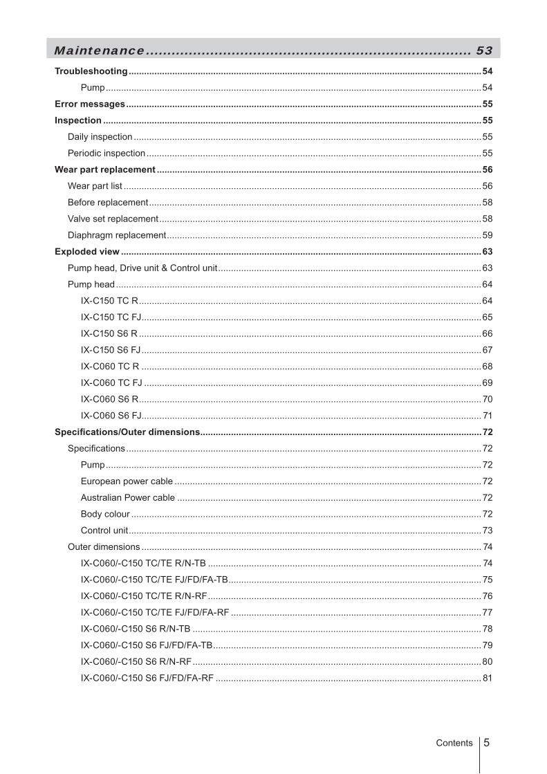
Maintenance ............................................................................ 53Troubleshooting ..........................................................................................................................................54
Pump ...................................................................................................................................................54
Error messages ...........................................................................................................................................55
Inspection ....................................................................................................................................................55
Daily inspection ........................................................................................................................................55
Periodic inspection ...................................................................................................................................55
Wear part replacement ...............................................................................................................................56
Wear part list ............................................................................................................................................56
Before replacement ..................................................................................................................................58
Valve set replacement ..............................................................................................................................58
Diaphragm replacement ...........................................................................................................................59
Exploded view .............................................................................................................................................63
Pump head, Drive unit & Control unit .......................................................................................................63
Pump head ...............................................................................................................................................64
IX-C150 TC R ......................................................................................................................................64
IX-C150 TC FJ .....................................................................................................................................65
IX-C150 S6 R ......................................................................................................................................66
IX-C150 S6 FJ .....................................................................................................................................67
IX-C060 TC R .....................................................................................................................................68
IX-C060 TC FJ ....................................................................................................................................69
IX-C060 S6 R ...................................................................................................................................... 70
IX-C060 S6 FJ..................................................................................................................................... 71
Specifications/Outer dimensions ..............................................................................................................72
Specifications ...........................................................................................................................................72
Pump ................................................................................................................................................... 72
European power cable ........................................................................................................................72
Australian Power cable .......................................................................................................................72
Body colour ......................................................................................................................................... 72
Control unit .......................................................................................................................................... 73
Outer dimensions ..................................................................................................................................... 74
IX-C060/-C150 TC/TE R/N-TB ........................................................................................................... 74
IX-C060/-C150 TC/TE FJ/FD/FA-TB ................................................................................................... 75
IX-C060/-C150 TC/TE R/N-RF ........................................................................................................... 76
IX-C060/-C150 TC/TE FJ/FD/FA-RF ..................................................................................................77
IX-C060/-C150 S6 R/N-TB ................................................................................................................. 78
IX-C060/-C150 S6 FJ/FD/FA-TB ......................................................................................................... 79
IX-C060/-C150 S6 R/N-RF .................................................................................................................80
IX-C060/-C150 S6 FJ/FD/FA-RF ........................................................................................................ 81
6 Safety instructions
Read through this section before use. This section describes important information for you to prevent personal injury or property damage.
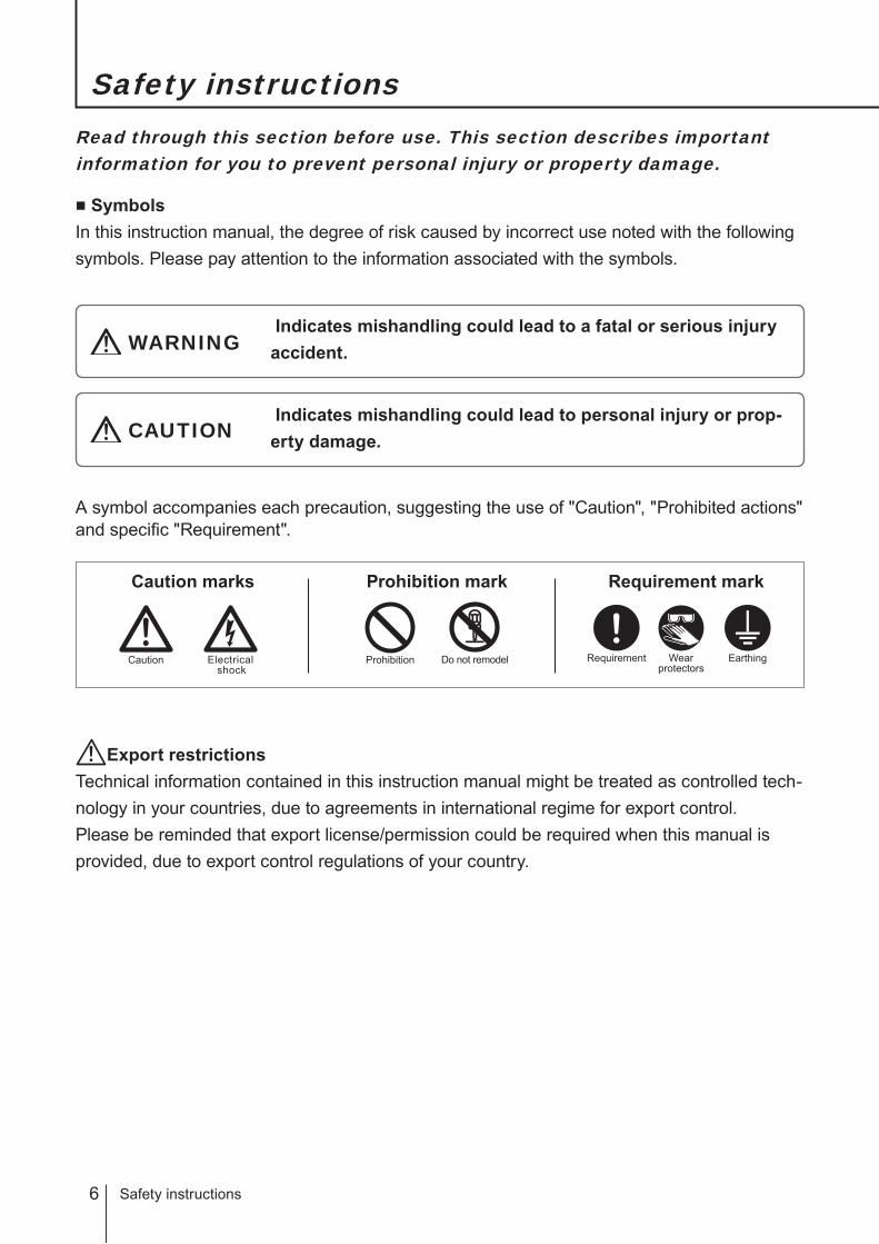
■ SymbolsIn this instruction manual, the degree of risk caused by incorrect use noted with the following symbols. Please pay attention to the information associated with the symbols.
Indicates mishandling could lead to a fatal or serious injury accident.WARNING
A symbol accompanies each precaution, suggesting the use of "Caution", "Prohibited actions" and specific "Requirement".
Indicates mishandling could lead to personal injury or prop-erty damage.CAUTION
Caution marks Prohibition mark Requirement mark
Safety instructions
ProhibitionElectricalshock
Caution Do not remodel Requirement Wearprotectors
Earthing
Export restrictionsTechnical information contained in this instruction manual might be treated as controlled tech-nology in your countries, due to agreements in international regime for export control.Please be reminded that export license/permission could be required when this manual is provided, due to export control regulations of your country.
7
Safety instructions
WARNING
WARNING
Turn off power before workRisk of electrical shock. Be sure to turn off power to stop the pump and
related devices before work.
Stop operationOn sensing any abnormality or danger, suspend operation immediately
and inspect/solve problems.
Do not use the pump in anything other than a specified purposeThe use of the pump in any purpose other than those clearly specified
may result in failure or injury. Use this product in a specified condition only.
Do not modify the pumpRemodelling the pump carries a high degree of risk. We are not responsi-
ble for any failure or injury results from remodelling.
Wear protective clothingAlways wear protective clothing such as an eye protection, chemical re-
sistant gloves, a mask and a work cap during dismantlement, assembly or
maintenance work.
Do not damage a power cableDo not pull or knot a power cable or place a heavy stuff on it. Damage to
the cable could lead to a fire or electrical shock when it is bared or discon-
nected.
Do not use the pump in a flammable atmosphereDo not place dangerous or flammable goods near the pump for your safety.
Prohibition
Requirement
Do not remodel
Wearprotectors
Electricalshock
Prohibition
Prohibition
8
CAUTION
A qualified operator only
The pump must be handled or operated by a qualified person with a full
understanding of the pump. Any person who is not familiar with this prod-
uct should not take part in operation or management.
Use a specified power only
Do not apply any power other than the one specified on the nameplate.
Otherwise, failure or fire may result. Also, be sure to earth the pump.
Do not wet electric parts or wiring
Risk of fire or electrical shock. Install the pump free from liquid spill.
Ventilation
Poisoning may result when handling a toxic or odorous liquid. Keep good
ventilation in your working area.
Do not install or store the pump in the following places where...
• Under a flammable atmosphere or in a dusty/humid place.
• Ambient temperature exceeds 50ºC or falls below 0ºC.
• Under direct sunlight or wind & rain.
Countermeasure against efflux
Take protective measures against an accidental chemical overflow results
from pump or piping breakage.
Prohibition
Requirement
Prohibition
Prohibition
Caution
Requirement
CAUTION

9
Safety instructions
Do not use the pump in a water place
The pump is not totally waterproof. The use of the pump in water or high
humidity could lead to electrical shock or short circuit.
Earthing
Risk of electrical shock. Always earth the pump.
Install an earth leakage breaker
An electrical failure of the pump may adversely affect related devices. Pur-
chase and install an earth leakage breaker separately.
Wear part replacement
Follow instructions in this manual for wear part replacement. Do not dis-
mantle the pump beyond the extent of the instructions.
Do not use a damaged pump
Using a damaged pump could lead to an electric leak or shock.
Disposal of a used pump
Dispose of any used or damaged pump in accordance with relevant regu-
lations. Consult a licensed industrial waste products disposing company.
Tighten the pump head
Liquid may leak if eight M8 (or six M5) pump head fixing bolts have been
loosened. Remove the bolt cover and tighten the bolts evenly to the speci-
fied torque below in diagonal order before initial operation and at regular
intervals.
Tightening torque
Model code Torque Bolts
IX-C150 12 N•m M8 hexagon head bolt × 8
IX-C060 3.5 N•m M5 hexagon head bolt × 6
Earthing
Prohibition
Requirement
Requirement
Caution
Prohibition
Electricalshock
CAUTION

10
Precautions for use
Precautions for use
• Electrical work should be performed by a qualified operator. Otherwise,
personal injury or property damage accident may result.
• Do not install the pump in the following places where...
–Under a flammable atmosphere or in a dusty/humid place.
–Under direct sunlight or wind & rain.
– Ambient temperature exceeds 50ºC or falls below 0ºC.
• Select a level location where is free from vibration and liquid can't stay.
Anchor the pump with four M8 bolts so as not to vibrate. If the pump is
installed at a tilt, a flow may reduce.
• When two or more pumps are installed, the pump operation interacts each
other and vibration becomes significant, resulting in poor performance or
failure of internal electrical devices. Select an installation location where
tolerates vibration to enough degree.
• Keep an ample working area around the pump for inspection and mainte-
nance.
• Install the pump as close to a supply tank as possible.
• Install the pump in a cool and dark place when handling liquids that readily
generate gas bubbles such as sodium hypochlorite or hydrazine solution.
Flooded suction application is strongly recommended for these liquids.
• A suction line bore should be wider than the inlet bore of the pump.
• Build up a flooded suction system for the viscous liquid delivery of
300mPa•S or more.
Caution
Caution
Caution
Requirement
Requirement
Requirement
Requirement
11
Safety instructions
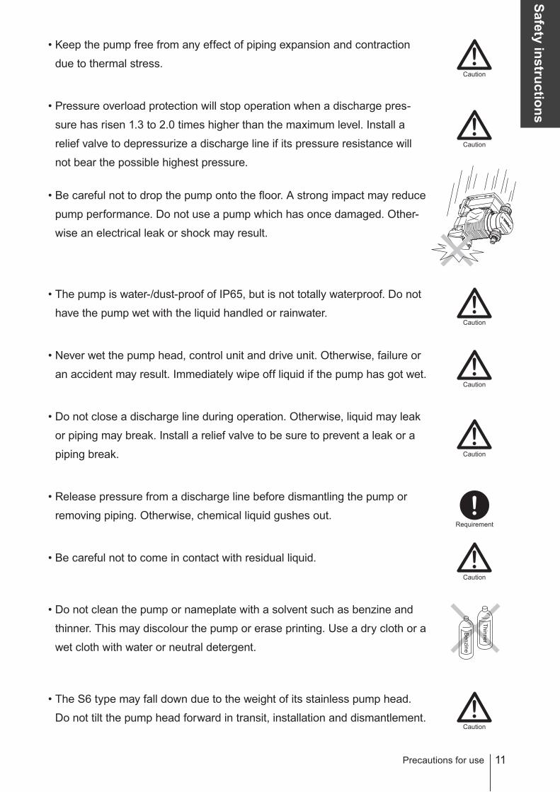
• Keep the pump free from any effect of piping expansion and contraction
due to thermal stress.
• Pressure overload protection will stop operation when a discharge pres-
sure has risen 1.3 to 2.0 times higher than the maximum level. Install a
relief valve to depressurize a discharge line if its pressure resistance will
not bear the possible highest pressure.
• Be careful not to drop the pump onto the floor. A strong impact may reduce
pump performance. Do not use a pump which has once damaged. Other-
wise an electrical leak or shock may result.
• The pump is water-/dust-proof of IP65, but is not totally waterproof. Do not
have the pump wet with the liquid handled or rainwater.
• Never wet the pump head, control unit and drive unit. Otherwise, failure or
an accident may result. Immediately wipe off liquid if the pump has got wet.
• Do not close a discharge line during operation. Otherwise, liquid may leak
or piping may break. Install a relief valve to be sure to prevent a leak or a
piping break.
• Release pressure from a discharge line before dismantling the pump or
removing piping. Otherwise, chemical liquid gushes out.
• Be careful not to come in contact with residual liquid.
• Do not clean the pump or nameplate with a solvent such as benzine and
thinner. This may discolour the pump or erase printing. Use a dry cloth or a
wet cloth with water or neutral detergent.
• The S6 type may fall down due to the weight of its stainless pump head.
Do not tilt the pump head forward in transit, installation and dismantlement.
Precautions for use
Caution
Caution
Caution
Requirement
Benzine
Thinner
Caution
Caution
Caution
Caution

12
Overview
Introduction
The information such as characteristics, features and part names are de-scribed in this section.
Introduction
Pump structure & Operating principle
The IX series is a diaphragm pump with a BLDC motor and features a high turndown ratio & automatic con-trols.
Principle of operationIn the IX series design, a BLDC motor rotation controls a flow rate.Motor rotation is transmitted to an eccentric cam through a reduction gear and then converted to reciprocating motion. Volumetric change occurs in the pump head as a diaphragm moves back and forth and pumps liquid along with valve action. A flow rate changes with a discharge speed while a suction speed is always the same at any flow rate.
Control unitPump head Drive unit
Pump head
Pump head valve(Discharge side)
Pump head valve(Suction side)
Eccentric cam
Diaphragm
Brushless motor
Keypads
IN
OUT
13
Overview
Features
● High turndown ratioUse of a BLDC control motor enables accurate control with a wide turndown ratio.
● High repeatabilityHighly-efficient valve design and accurate discharge-/suction-speed controls assure the high repeatability of chemical dosing (±1%).
● Energy-saving designUse of helical gears and an assist spring reduces power consumption by 70% compared to our existing me-tering pump designs (spring back).
● Automatic controlThe IX can automatically run along with analogue-, pulse-, batch- or interval batch-operation programming.
● Multivoltage operationThe IX series can be used in all countries thanks to the universal power voltage (100-240VAC).
● Safety designA diaphragm rupture detection ensures user safety and a pressure overload detection protects the pump and pipework from an accidental discharge line pressure rise.
● Ingress protection rating of IP65
Operational functions
Manual mode
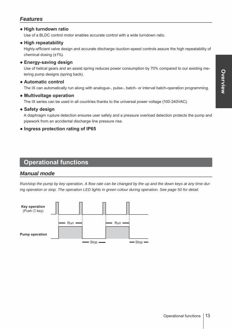
Run/stop the pump by key operation. A flow rate can be changed by the up and the down keys at any time dur-ing operation or stop. The operation LED lights in green colour during operation. See page 50 for detail.
Key operation(Push key)
Pump operation
Run
Stop
Run
Stop
Operational functions

14
EXT mode
■ Analogue control (See page 40 & 50)Select a proportional control pattern. 4 - 20mA, 20 - 4mA, 0 - 20mA and 20 - 0mA are available.
The left graph is in the following patterns.a. 4 - 20mAb. 20 - 4mAc. 0 - 20mAd. 20 - 0mA
* A flow rate falls to 0mL/H if the pump runs beneath the minimum rate. The pump does not run over the maximum flow rate at any current value.
Example of use: pH control in a water treatment system
■ Pulse control (See page 41 & 50) A flow rate is automatically controlled by flow volume (ml) per pulse and a pulse signal frequency from a flow meter.* It takes about 10 pulses for the IX to catch up with the change of the frequency.
Example of use: Chemical dosing in a sewage treatment system
Flow meter
Pulse signal
Flow
Pump
Supply tank
Supply tank
pH meter
Electrode
Pump
4-20mA signal
10Hz 5Hz 10Hz
0
Pulse signal
Flow rate at 10Hz
Fow rate at 5Hz
Operational functions
0 4 20
a
d
c
b
Flow rate[L/H]
4-20mA analogue signal
Max
Min

15
Overview
■ Batch control (See page 41 & 50)The IX discharges a programmed flow volume per pulse. When the pump receives pulse signals in dosing, the next dosing is sequentially processed. The signals are stored up to 65535.
* The pump runs to meet the programmed flow rate in the manual mode (MAN speed). Set it to the max in that mode before starting batch control.
Example of use: Chemical dosing in a production line system
■ Interval batch control (See page 41 & 50)To make an interval batch control, set a date and time interval and a flow rate. The IX discharges the pro-grammed flow rate at a set interval. In the diagram below, the interval is set to 1 hour.
* The pump runs to meet the programmed flow rate in the manual mode (MAN speed).
Example of use: Water transfer for a sprinkler system
Pulse signal/Push of key
1 hrTime
Flow
2 hr 3 hr
Operational functions
Pump
Supply tank (water) Pulse signal
Volume per pulse Volume for 2 pulse
Flow
Pulse signal
Supply tank
Pulse signal
Pump
Proximity switch
16
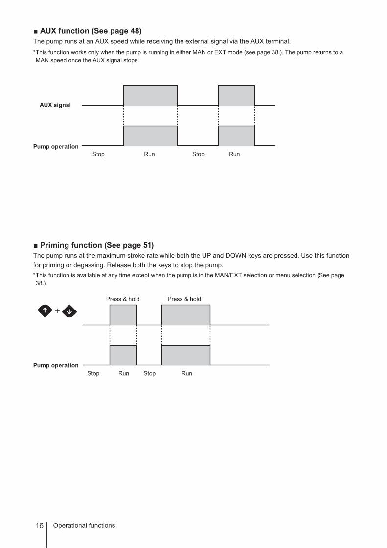
■ AUX function (See page 48)The pump runs at an AUX speed while receiving the external signal via the AUX terminal.
* This function works only when the pump is running in either MAN or EXT mode (see page 38.). The pump returns to a MAN speed once the AUX signal stops.
■ Priming function (See page 51)The pump runs at the maximum stroke rate while both the UP and DOWN keys are pressed. Use this function for priming or degassing. Release both the keys to stop the pump.* This function is available at any time except when the pump is in the MAN/EXT selection or menu selection (See page 38.).
Operational functions
AUX signal
Pump operationRunStop RunStop
Press & hold
RunStop StopPump operation
Press & hold
Run

17
Overview
Operational functions
■ STOP function (See page 42)The start/stop of operation can be controlled by a signal from a level sensor.See page 30 "STOP signal" for wiring diagram.
Example of use: Liquid level monitoring
The pump stops when liquid has fallen below the minimum level.
■ Pre-STOP function (See page 42 & 43)Liquid level in a supply tank can be monitored by a signal from a level sensor. See page 30 for wiring diagram.The operation LED changes from green to orange colour when the pump is receiving the Pre-STOP signal from a level sensor in operation. See page 30 "STOP signal" for wiring diagram.
Example of use: Liquid level monitoring
The operation LED lights in orange colour to inform a user that liquid comes close to the minimum level in a supply tank.
LED lightsin orange.
Pre STOP signal
Pump ON
Level sensor
Liquid is near the minimum level.
Flow
STOP signal
Pump OFF
Level sensor
Flow
Liquid is below the minimum level.
LED lights in red.

18 Operational functions
Protective functions
■ Interlock function (See page 42 & 43)The start/stop of operation can be controlled by a signal from an external device. See page 30 "STOP signal" for wiring diagram. Interlock function works in the same way as the STOP function but uses a preference cir-cuit. Use this function for emergency stop.
■ Diaphragm rupture detection (See page 42 &43)The pump stops right after a built-in sensor detects a leak in the compartment at the back of the diaphragm. In this state the operation LED lights in red colour. Replace a broken diaphragm as necessary. See page 59 for diaphragm replacement. To release this error condition, push the start/stop key (or the ESC key under Profibus control.).
NOTEThis capacitance sensor does not work properly if liquid conductivity is 1mS/m or below. Before sending pure water, oil or any other low-conductivity liquid, check its conductivity to see if it meets the minimum level. Do not use this function when it is 1mS/m or below. Instead, check the diaphragm for damage and replace it on finding a leak from the drain port. Otherwise, the pump may fail.
■ Pressure overload detectionThe pump stops right after a built-in sensor detects 1.3-2.0 times higher discharge pressure than the maximum level. In this state the operation LED flashes in red colour. The pump resumes operation 30 seconds after the stoppage. If pressure overload has recurred 5 times consecutively, the pump will not resume operation any more and will keep still. Push the start/stop key to release this state.
NOTEA detection level varies with operating conditions and a piping layout within the above pressure range. Set up a relief valve if the pressure resistance of other related devices is lower than that rage.
OFF
ON
Run Stop
Sensor signal
Pump operation
A leak is detected.
OFF
ON1 2 3 4 5times
30sec 30sec 30sec 30sec
Sensor signal
Pump operation
Run Stop
19
Overview
Operational functions
■ Output function (See page 44 & 45) Set the STOP, Pre-STOP, Interlock, Diaphragm rupture detection and Pressure overload detection outputs to the Alarm1 and Alarm2. See page 31 "Output signal" for wiring diagram.
Alarm1: Mechanical relay output(No voltage contact 1a×1 250VAC 3A Resistive load)Alarm2: PhotoMOS relay output(No voltage contact 1a×1 24VAC/DC 0.1A Resistive load)
Other functions
■ Suction speed setting (See page 47)Suction speed is adjustable by 4 levels depending on liquid property. Reduce suction speed so as to prevent cavitation when delivering viscous or gaseous liquid.Select 100% (default), 75%, 50% or 25%.
■ Diaphragm position adjustment (See page 47 & 48)A pump shaft expands or contracts to help diaphragm replacement.Select "MAX OUT Pos." through the "Other Features" menu in order to extend the pump shaft to the maximum for the replacement of the diaphragm. Select "MAX IN Pos." to contract the pump shaft and mount the pump head. See page 59 "Diaphragm replacement" for detail.
■ Anti chattering programming (See page 47 & 48)Program a pulse recognition time for the IX not to be adversely affected by chattering or noise.Factory default setting is 5msec. This means the pump recognizes a pulse length of 5msec or more. Select 1 or 2msec if a pulse length is shorter than 5msec, however, note the shorter the recognition time is, the more susceptible to the interference of noise the pump becomes.Note the maximum allowable input frequency of the IX is 100Hz.
■ Flow unit setting (See page 47 & 48)Select L/H or GPH for flow rate indication.
■ Language setting (See page 47 & 49)Select your language through language selection.
■ Keypad lock (See page 52)Activate keypad lock for the prevention of erroneous key operation.
■ DefaultPower on the pump while pressing the ESC key to recall default setting. Note the flow volume per shot ob-tained through the calibration process (see page 35) remains the same.
20 Part names
Part names
Pump
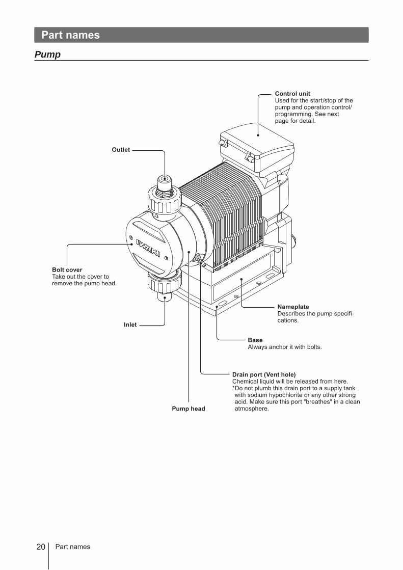
Control unitUsed for the start/stop of the pump and operation control/programming. See next page for detail.
Bolt coverTake out the cover to remove the pump head.
Drain port (Vent hole)Chemical liquid will be released from here.* Do not plumb this drain port to a supply tank with sodium hypochlorite or any other strong acid. Make sure this port "breathes" in a clean atmosphere.
NameplateDescribes the pump specifi-cations.
BaseAlways anchor it with bolts.
Outlet
Pump head
Inlet
21
Overview
Part names
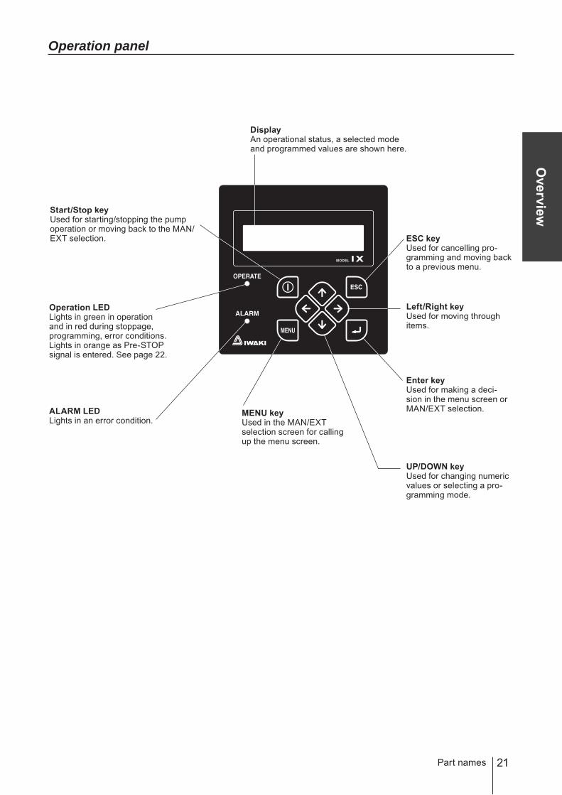
Operation panel
UP/DOWN keyUsed for changing numeric values or selecting a pro-gramming mode.
MENU keyUsed in the MAN/EXT selection screen for calling up the menu screen.
Left/Right keyUsed for moving through items.
DisplayAn operational status, a selected mode and programmed values are shown here.
Start/Stop keyUsed for starting/stopping the pump operation or moving back to the MAN/EXT selection. ESC key
Used for cancelling pro-gramming and moving back to a previous menu.
ALARM LEDLights in an error condition.
Operation LEDLights in green in operation and in red during stoppage, programming, error conditions.Lights in orange as Pre-STOP signal is entered. See page 22.
Enter keyUsed for making a deci-sion in the menu screen or MAN/EXT selection.

22
■ Basic displays and Pump states
Display Operation LEDlights in red
Operation LEDlights in green
Operation LEDlights in orange
ALARM LEDlights in red
Ope
ratio
n
― Operation in manual mode ― ―
―Operation in EXT mode (Analogue control)
― ―
― AUX operation ― ―
― Operation in prim-ing mode ― ―
― ― Pre-STOP func-tion is active. ―*
Sto
p
A wait state in manual mode ― ― ―
A wait state in EXT mode (ana-logue control)
― ― ―
MAN/EXT selec-tion ― ― ―
Menu screen ― ― ―
Pressure overload protection is ac-tive.
― ― ―*
Diaphragm is bro-ken. ― ―
Leak detection( Alarm 1 default setting)*
Sensor failure ― ― ―
Operation stop in manual mode ― ― ―*
― ― ―Interlock function
activation (Alarm 2 default setting)*
* The Alarm LED becomes active when a function is allocated to Alarm 1 or 2.
Part names
23
Overview
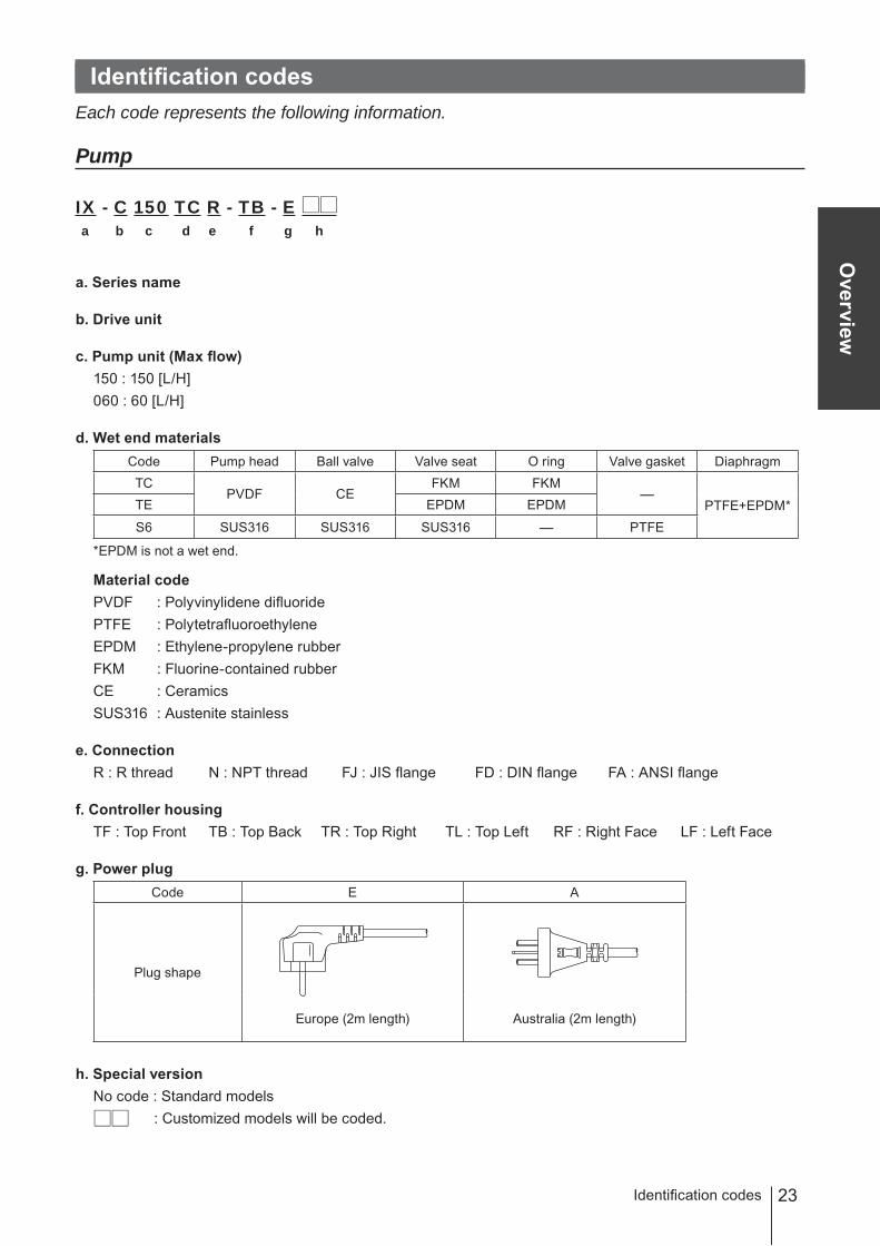
Identification codesEach code represents the following information.
Pump
IX - C 150 TC R - TB - E a b c d e f g h
a. Series name
b. Drive unit
c. Pump unit (Max flow)150 : 150 [L/H]060 : 60 [L/H]
d. Wet end materialsCode Pump head Ball valve Valve seat O ring Valve gasket DiaphragmTC
PVDF CEFKM FKM
―PTFE+EPDM*TE EPDM EPDM
S6 SUS316 SUS316 SUS316 ― PTFE
*EPDM is not a wet end.
Material codePVDF : Polyvinylidene difluoridePTFE : PolytetrafluoroethyleneEPDM : Ethylene-propylene rubberFKM : Fluorine-contained rubberCE : CeramicsSUS316 : Austenite stainless
e. ConnectionR : R thread N : NPT thread FJ : JIS flange FD : DIN flange FA : ANSI flange
f. Controller housingTF : Top Front TB : Top Back TR : Top Right TL : Top Left RF : Right Face LF : Left Face
g. Power plugCode E A
Plug shape
Europe (2m length) Australia (2m length)
h. Special versionNo code : Standard models : Customized models will be coded.
Identification codes

24
InstallationThis section describes the installation of the pump, piping and wiring. Read through this section before work.
Points to be observedObserve the following points when installing the pump.• Be sure to turn off power to stop the pump and related devices before work.• Upon sensing abnormality or danger, stop work immediately. Remove problems before
resuming work.• Do not place dangerous or flammable goods near the pump for your safety.• Risk of an electrical leak or shock. Do not use a damaged pump.
Pump mounting
Select an installation location and mount the pump.
Necessary tools• Four M8 bolts (pump mounting) • Adjustable wrench or spanner
Select a suitable place.Always select a flat floor free of vibrations. See page 10 for detail.
Anchor the pump by four M8 bolts.Be sure to fix the pump at four points.
NOTEInstall the pump horizontally. If the pump is installed at a tilt, the flow may reduce.
1
2
Pump mounting

25
Installation
Pipework
■ Piping layout
Flooded suction application Suction lift application
NOTE• A suction line bore should be wider than the inlet bore of the pump.• Flooded suction is recommended when handling a gaseous liquid such as sodium hypochlorite or high-vis-
cosity liquid.• Observe the permitted force of 100N and moment of 10N•m to the inlet and outlet of the pump head. Support
your piping system as necessary so as not to go over the allowable moment.
Pipework
Accumulator/Chamber
Pump
Relief valve
Pressure valve
Air vent/drain valve
Calibration cylinder
Tank
Relief valve
Accumulator/Chamber
Pump
Pressure valve
Calibration cylinder
Air vent/drain valve
Tank
26
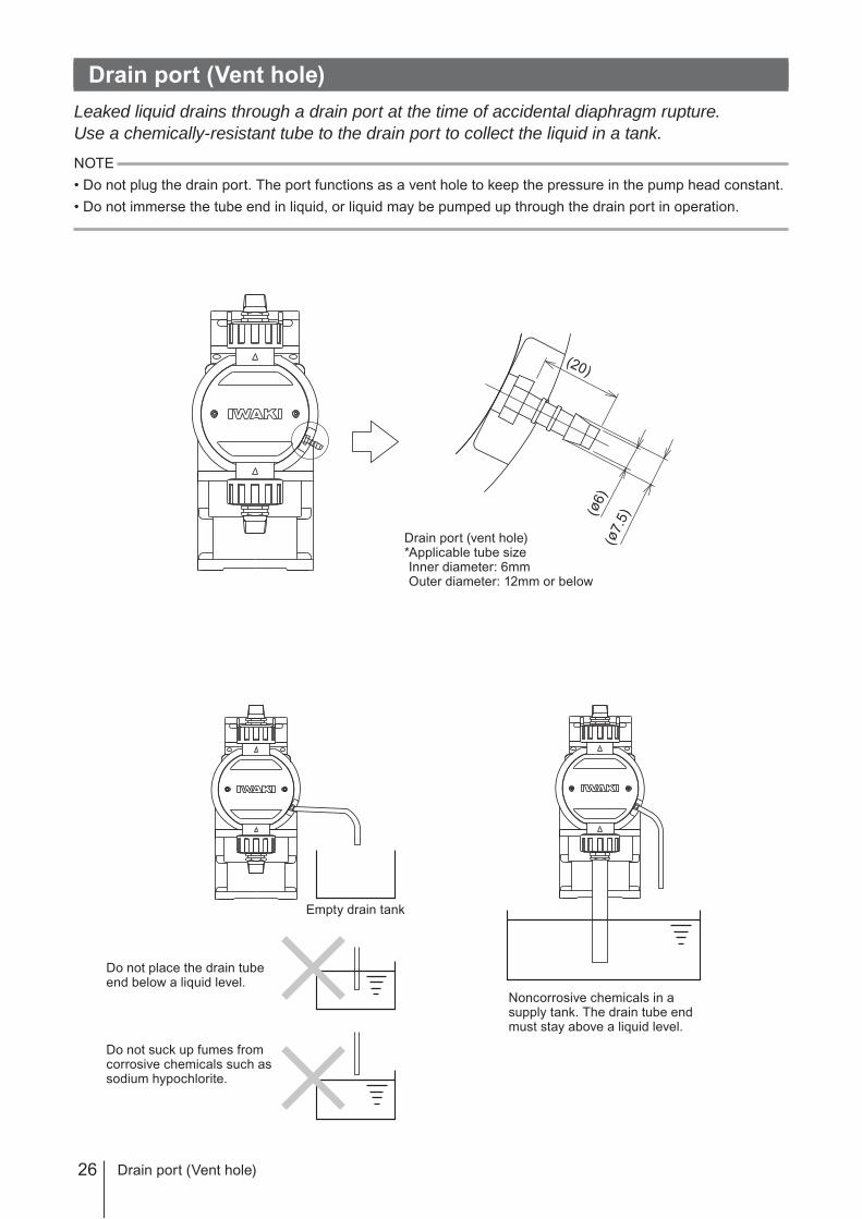
Drain port (Vent hole)Leaked liquid drains through a drain port at the time of accidental diaphragm rupture.Use a chemically-resistant tube to the drain port to collect the liquid in a tank.
NOTE• Do not plug the drain port. The port functions as a vent hole to keep the pressure in the pump head constant.• Do not immerse the tube end in liquid, or liquid may be pumped up through the drain port in operation.
(ø6)
(ø7.
5)
(20)
Drain port (vent hole)*Applicable tube sizeInner diameter: 6mmOuter diameter: 12mm or below
Drain port (Vent hole)
Empty drain tank
Do not place the drain tube end below a liquid level.
Do not suck up fumes from corrosive chemicals such as sodium hypochlorite.
Noncorrosive chemicals in a supply tank. The drain tube end must stay above a liquid level.

27
Installation
Wiring
WiringWiring for power voltage, earthing and external signals.
Points to be observedObserve the following points during wiring work.• Electrical work should be performed by a qualified operator. Always observe applicable
codes or regulations.• Observe the rated voltage range, or the electrical circuit in the control unit may fail.• Do not perform wiring work while electric power is on. Otherwise, an electrical shock or
a short circuit may result. Be sure to turn off the power before wiring work.• Be careful for electric power not to be turned on during work.• Replacement of a power cable should be conducted by a manufacturer, his agency or a
skilled person. Otherwise, an accident may result.
End terminalsSee the following diagram for detail.
AUX
STOPOutput
EXT
Fieldbus
Power cable (1950mm)
28
Power voltage/Earthing
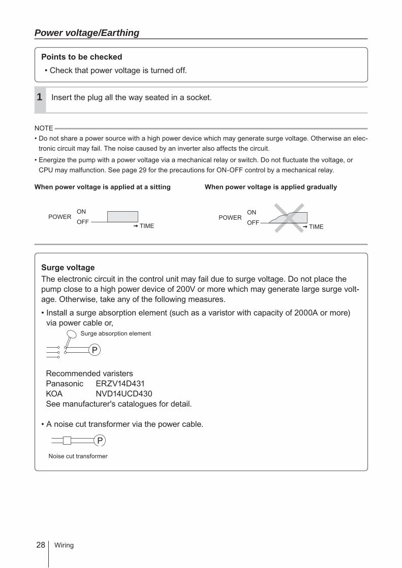
Points to be checked• Check that power voltage is turned off.
Insert the plug all the way seated in a socket.
NOTE• Do not share a power source with a high power device which may generate surge voltage. Otherwise an elec-
tronic circuit may fail. The noise caused by an inverter also affects the circuit.
• Energize the pump with a power voltage via a mechanical relay or switch. Do not fluctuate the voltage, or CPU may malfunction. See page 29 for the precautions for ON-OFF control by a mechanical relay.
When power voltage is applied at a sitting When power voltage is applied gradually
Surge voltageThe electronic circuit in the control unit may fail due to surge voltage. Do not place the pump close to a high power device of 200V or more which may generate large surge volt-age. Otherwise, take any of the following measures.
• Install a surge absorption element (such as a varistor with capacity of 2000A or more) via power cable or,
Recommended varistersPanasonic ERZV14D431KOA NVD14UCD430See manufacturer's catalogues for detail.
• A noise cut transformer via the power cable.
Surge absorption element
Noise cut transformer
POWERON
OFF TIMEPOWER
ON
OFF TIME
1
Wiring

29
Installation
Wiring
Precautions for ON-OFF control by a mechanical relayThe control unit is equipped with CPU. Always start/stop the pump by the STOP signal for ON-OFF control. Try not to turn on and off the main power. Otherwise, observe the fol-lowing points.• Do not turn ON/OFF power voltage more than six times per hour.• When using a mechanical relay for ON-OFF operation, its contact capacity should be
5A or more. Contact point may fail if it is less than 5A.• If a mechanical relay with the contact capacity of 5A is used, the maximum allowable
ON/OFF operation is about 150,000 times. The contact capacity should be 10A or more when making ON-OFF operation over 150,000 times or sharing a power source with a large capacity equipment. Otherwise a contact point may fail by surge voltage.
• Use a solid state relay (SSR) as necessary (such as the OMRON G3F). See manufac-turer's catalogues for detail.
• Turning off power voltage, operation stops with an extended pump shaft after the com-pletion of the last discharge process.
Signal wire connection
Points to be checked• Check that power voltage is turned off.
Use our optional connector cables below or purchase DIN 4- and 5-pin female connector cables when using signal input and output.
Optional 5m DIN connector cables EXT terminal is for Input signal STOP terminal is for STOP and AUX signals OUT terminal is for Output signal
NOTE• Do not lay on these signal cables in parallel with a power cable. Otherwise noise is generated through the
cables due to induction effect and it results in malfunction or failure.• The following products are the recommended SSRs (Solid State Relays) for signal input. Any other SSRs
may cause malfunction. See manufacturer's information for details on these SSRs.–OMRON G3FD-102S or G3FD-102SN–OMRON G3TA-IDZR02S or G3TA-IDZR02SM
• When using a mechanical relay for signal input, its minimum application load should be 5mA or below.• Insert the DIN 4- or 5-pin female connector as far as it will go and then tighten the skirt to make a secure con-
nection.
*Use either a no-voltage contact or an open collector for the input, STOP and AUX signals.
30
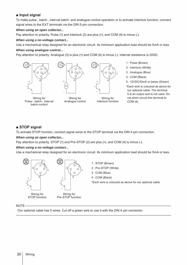
■ Input signalTo make pulse-, batch-, interval batch- and analogue-control operation or to activate interlock function, connect signal wires to the EXT terminals via the DIN 5-pin connection.
When using an open collector...Pay attention to polarity. Pulse (1) and Interlock (2) are plus (+), and COM (4) is minus (-).
When using a no-voltage contact...Use a mechanical relay designed for an electronic circuit. Its minimum application load should be 5mA or less.
When using analogue control...Pay attention to polarity. Analogue (3) is plus (+) and COM (4) is minus (-). Internal resistance is 200Ω.
1 : Pulse (Brown)
2 : Interlock (White)
3 : Analogue (Blue)
4 : COM (Black)
5 : 12VDC30mA or below (Green)
* Each wire is coloured as above for our optional cable. The terminal 5 is an output and is not used. Do not short-circuit this terminal to COM (4).
■ STOP signalTo activate STOP function, connect signal wires to the STOP terminal via the DIN 4-pin connection.
When using an open collector...Pay attention to polarity. STOP (1) and Pre-STOP (2) are plus (+), and COM (4) is minus (-).
When using a no-voltage contact...Use a mechanical relay designed for an electronic circuit. Its minimum application load should be 5mA or less.
1 : STOP (Brown)
2 : Pre-STOP (White)
3 : COM (Blue)
4 : COM (Black)
* Each wire is coloured as above for our optional cable.
NOTEOur optional cable has 5 wires. Cut off a green wire to use it with the DIN 4-pin connector.
Wiring forSTOP function
3
2
4
13
2
4
1
Wiring forPre-STOP function
Wiring forInterlock function
3
2
4
5 13
2
4
5 13
2
4
5 1
Wiring forAnalogue control
Wiring forPulse-, batch-, interval
batch-control
Wiring

31
Installation
■ AUX signalTo activate AUX function, connect signal wires to the AUX terminal via the DIN 5-pin connection.
When using an open collector...Pay attention to polarity. AUX (3) is plus (+), and COM (4) is minus (-).
When using a no-voltage contact...Use a mechanical relay designed for an electronic circuit. Its minimum application load should be 5mA or less.
1 : N.C. (Brown)
2 : N.C. (White)
3 : AUX (Blue)
4 : COM (Black)
5 : 12VDC30mA or below (Green)
* Each wire is coloured as above for our optional cable. The terminal 5 is an output and is not used. Do not short-circuit this terminal to COM (4).
■ Output signalTo transmit signal to an external device, connect signal wires to the OUT terminal via the DIN 4-pin connection.
Alarm1<Mechanical relay>: Enable or disable STOP, Pre-STOP, Interlock, Motor overload and Leak detection individually.*Leak detection only is enabled at factory default setting.
Alarm2<PhotoMOS relay>: Enable or disable STOP, Pre-STOP, Interlock, Motor overload and Leak detection individually.*Interlock only is enabled at factory default setting.
1 : Alarm1 (White)2 : Alarm1 (Brown)3 : Alarm2 (Black)4 : Alarm2 (Blue)
* Each wire is coloured as above for our optional cable.
Mounting direction of the output signal cableMount the DIN square connector cable in the following direction and secure it with a M3 screw.
3
2
4
5 1
Wiring forAUX function
1
2
3
4
Wiring
Output signal cable
M3 screw
32
This section describes pump operation and programming. Run the pump after pipework and wiring is completed.
Before operationFirst check piping and wiring are correct. And then make commissioning before starting op-eration.
Points to be checkedBefore operation, check if...• Liquid level in a supply tank is enough.• Piping is securely connected and is free from leakage and clogging.• Discharge/suction valves are opened.• Power voltage range is correct.• Electrical wiring is correct and is free from the risk of short circuit and electrical leakage.
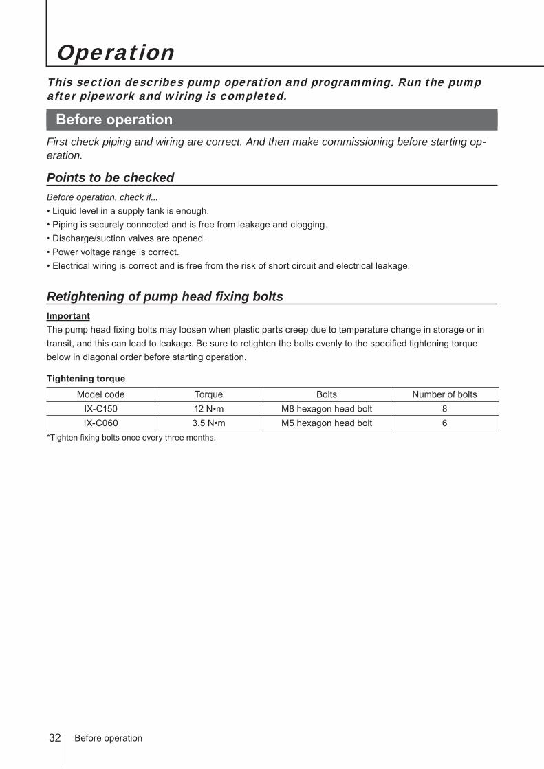
Retightening of pump head fixing boltsImportantThe pump head fixing bolts may loosen when plastic parts creep due to temperature change in storage or in transit, and this can lead to leakage. Be sure to retighten the bolts evenly to the specified tightening torque below in diagonal order before starting operation.
Tightening torque
Model code Torque Bolts Number of boltsIX-C150 12 N•m M8 hexagon head bolt 8IX-C060 3.5 N•m M5 hexagon head bolt 6
*Tighten fixing bolts once every three months.
Operation
Before operation

33
Operation
CommissioningAlways make commissioning when first mounting the pump in your system or resuming operation after a long period of stoppage.
Open an air vent and a suction line.Do not open a calibration line if any.
Supply the rated power voltage to the pump.
Start the pump at a low flow rate and gradually increase it to a target rate.Continue operation for 10 minutes and check the pump and pipework for any abnormality.
Close an air vent line to pump liquid to a main line.
Before a long period of stoppage (One month or more)Clean wet ends and the inside of piping.• Run the pump with clean water for about 30 minutes to rinse chemicals off.
Before unplugging the pump• Always stop the pump by key operation and wait for three seconds before unplugging the pump. Otherwise,
the last key operation may not be put in memory. In this case the pump unintentionally starts to run as pow-ered on, discharging liquid.
When the pump does not transfer liquid at resuming operation.• Clean the valve sets and remove foreign matters.• If air is in the pump head, expel air through the above commissioning procedure.
Open
Open
Close
Air vent valve
2
1
3
4
Before operation
34
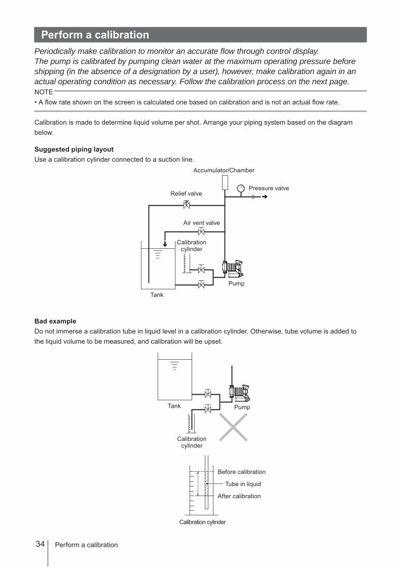
Perform a calibrationPeriodically make calibration to monitor an accurate flow through control display.The pump is calibrated by pumping clean water at the maximum operating pressure before shipping (in the absence of a designation by a user), however, make calibration again in an actual operating condition as necessary. Follow the calibration process on the next page.NOTE• A flow rate shown on the screen is calculated one based on calibration and is not an actual flow rate.
Calibration is made to determine liquid volume per shot. Arrange your piping system based on the diagram below.
Suggested piping layoutUse a calibration cylinder connected to a suction line.
Bad example Do not immerse a calibration tube in liquid level in a calibration cylinder. Otherwise, tube volume is added to the liquid volume to be measured, and calibration will be upset.
Perform a calibration
Accumulator/Chamber
Pump
Relief valve
Air vent valve
Pressure valve
Calibration cylinder
Tank
Before calibration
Pump
After calibration
Calibration cylinder
Tube in liquid
Calibration cylinder
Tank
35
Operation
Perform a calibration
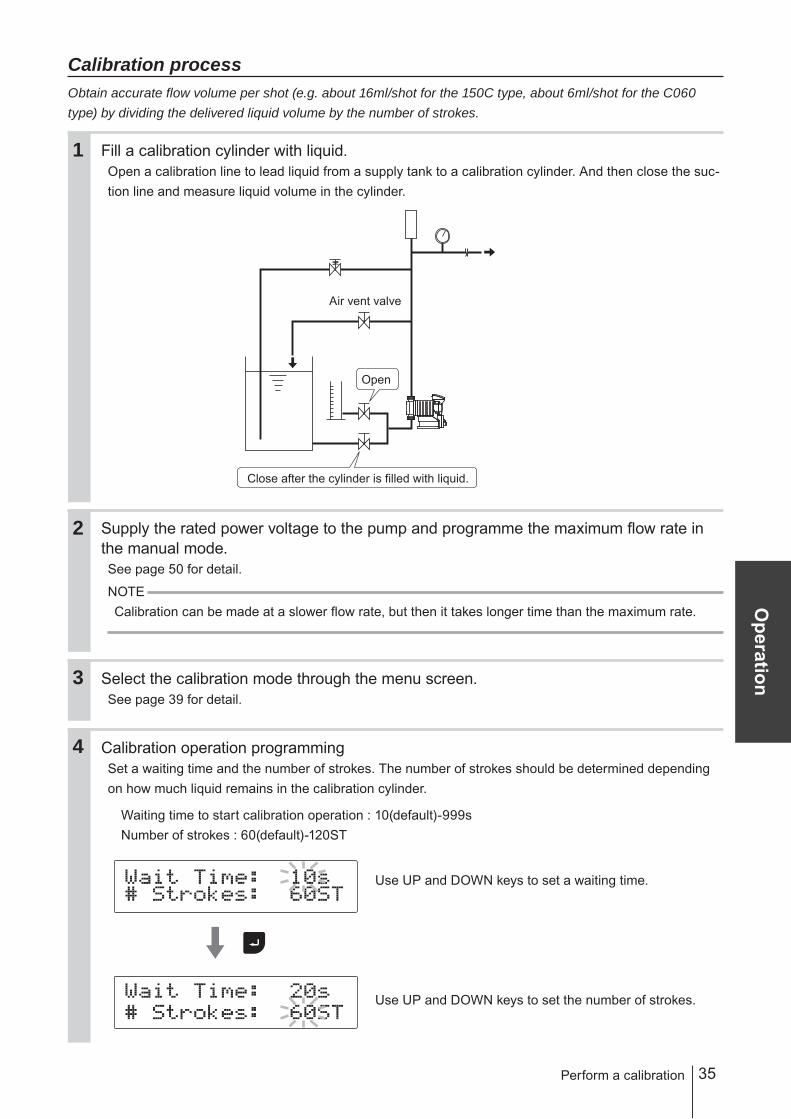
Calibration processObtain accurate flow volume per shot (e.g. about 16ml/shot for the 150C type, about 6ml/shot for the C060 type) by dividing the delivered liquid volume by the number of strokes.
Fill a calibration cylinder with liquid.Open a calibration line to lead liquid from a supply tank to a calibration cylinder. And then close the suc-tion line and measure liquid volume in the cylinder.
Supply the rated power voltage to the pump and programme the maximum flow rate in the manual mode.See page 50 for detail.
NOTECalibration can be made at a slower flow rate, but then it takes longer time than the maximum rate.
Select the calibration mode through the menu screen.See page 39 for detail.
Calibration operation programmingSet a waiting time and the number of strokes. The number of strokes should be determined depending on how much liquid remains in the calibration cylinder.
Waiting time to start calibration operation : 10(default)-999sNumber of strokes : 60(default)-120ST
Use UP and DOWN keys to set a waiting time.
Use UP and DOWN keys to set the number of strokes.
2
1
3
Close after the cylinder is filled with liquid.
Open
Air vent valve
4

36
Start calibration operation.
Push the Enter key after setting the number of strokes. The pump starts a countdown.
The pump starts to run for the set number of strokes as it comes to zero.
Measure liquid volume in the calibration cylinder again.
Enter how much liquid has reduced.
Use the UP and DOWN keys to set the volume reduction.
Push the Enter key once. The screen shows flow volume per shot. Calibration now has been completed.* The screen shows "ERROR! Volume Out Of Range!!" if the reduction is too little or too large. Enter correct liquid volume or
recalibrate it.
NOTECalibration with high viscosity liquid at a full suction speed will often give rise to this error. Reduce a suction speed along with viscosity.
Push the ESC key to return to the wait mode.
Pumpstops
5
6
Pumpstarts
7
Perform a calibration
37
Operation
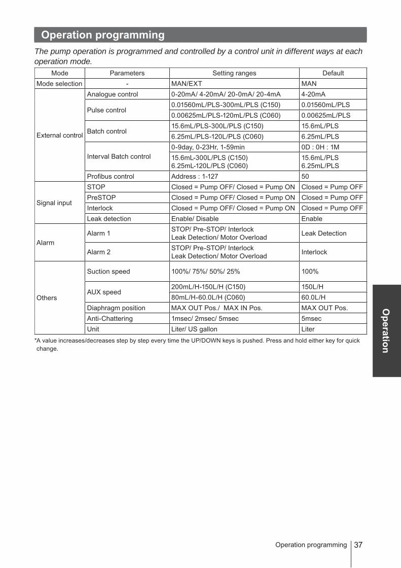
Operation programmingThe pump operation is programmed and controlled by a control unit in different ways at each operation mode.
Mode Parameters Setting ranges DefaultMode selection - MAN/EXT MAN
External control
Analogue control 0-20mA/ 4-20mA/ 20-0mA/ 20-4mA 4-20mA
Pulse control0.01560mL/PLS-300mL/PLS (C150) 0.01560mL/PLS0.00625mL/PLS-120mL/PLS (C060) 0.00625mL/PLS
Batch control15.6mL/PLS-300L/PLS (C150) 15.6mL/PLS6.25mL/PLS-120L/PLS (C060) 6.25mL/PLS
Interval Batch control0-9day, 0-23Hr, 1-59min 0D : 0H : 1M15.6mL-300L/PLS (C150)6.25mL-120L/PLS (C060)
15.6mL/PLS6.25mL/PLS
Profibus control Address : 1-127 50
Signal input
STOP Closed = Pump OFF/ Closed = Pump ON Closed = Pump OFFPreSTOP Closed = Pump OFF/ Closed = Pump ON Closed = Pump OFFInterlock Closed = Pump OFF/ Closed = Pump ON Closed = Pump OFFLeak detection Enable/ Disable Enable
AlarmAlarm 1 STOP/ Pre-STOP/ Interlock
Leak Detection/ Motor Overload Leak Detection
Alarm 2 STOP/ Pre-STOP/ InterlockLeak Detection/ Motor Overload Interlock
Others
Suction speed 100%/ 75%/ 50%/ 25% 100%
AUX speed200mL/H-150L/H (C150) 150L/H80mL/H-60.0L/H (C060) 60.0L/H
Diaphragm position MAX OUT Pos./ MAX IN Pos. MAX OUT Pos.Anti-Chattering 1msec/ 2msec/ 5msec 5msecUnit Liter/ US gallon Liter
* A value increases/decreases step by step every time the UP/DOWN keys is pushed. Press and hold either key for quick change.
Operation programming
38
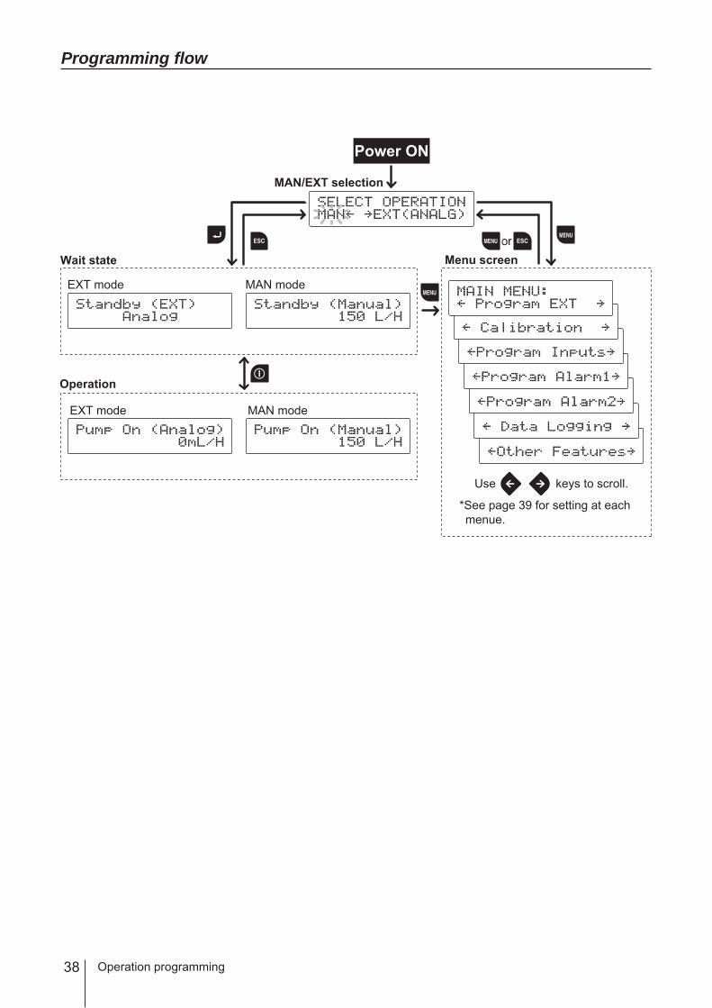
Programming flow
Operation programming
Wait state
Operation
MAN modeEXT mode
Menu screen
MAN/EXT selection
Power ON
or
Use keys to scroll.
*See page 39 for setting at each menue.
MAN modeEXT mode
39
Operation
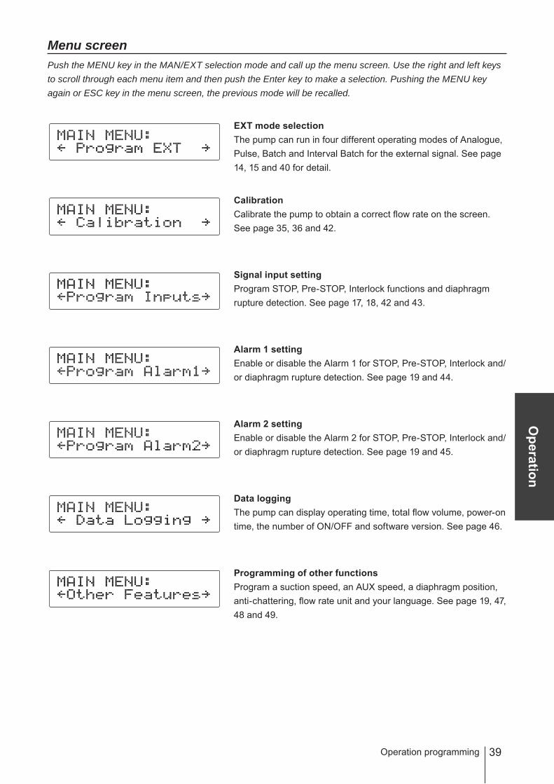
Menu screenPush the MENU key in the MAN/EXT selection mode and call up the menu screen. Use the right and left keys to scroll through each menu item and then push the Enter key to make a selection. Pushing the MENU key again or ESC key in the menu screen, the previous mode will be recalled.
EXT mode selectionThe pump can run in four different operating modes of Analogue, Pulse, Batch and Interval Batch for the external signal. See page 14, 15 and 40 for detail.
CalibrationCalibrate the pump to obtain a correct flow rate on the screen. See page 35, 36 and 42.
Signal input settingProgram STOP, Pre-STOP, Interlock functions and diaphragm rupture detection. See page 17, 18, 42 and 43.
Alarm 1 settingEnable or disable the Alarm 1 for STOP, Pre-STOP, Interlock and/or diaphragm rupture detection. See page 19 and 44.
Alarm 2 settingEnable or disable the Alarm 2 for STOP, Pre-STOP, Interlock and/or diaphragm rupture detection. See page 19 and 45.
Data loggingThe pump can display operating time, total flow volume, power-on time, the number of ON/OFF and software version. See page 46.
Programming of other functionsProgram a suction speed, an AUX speed, a diaphragm position, anti-chattering, flow rate unit and your language. See page 19, 47, 48 and 49.
Operation programming
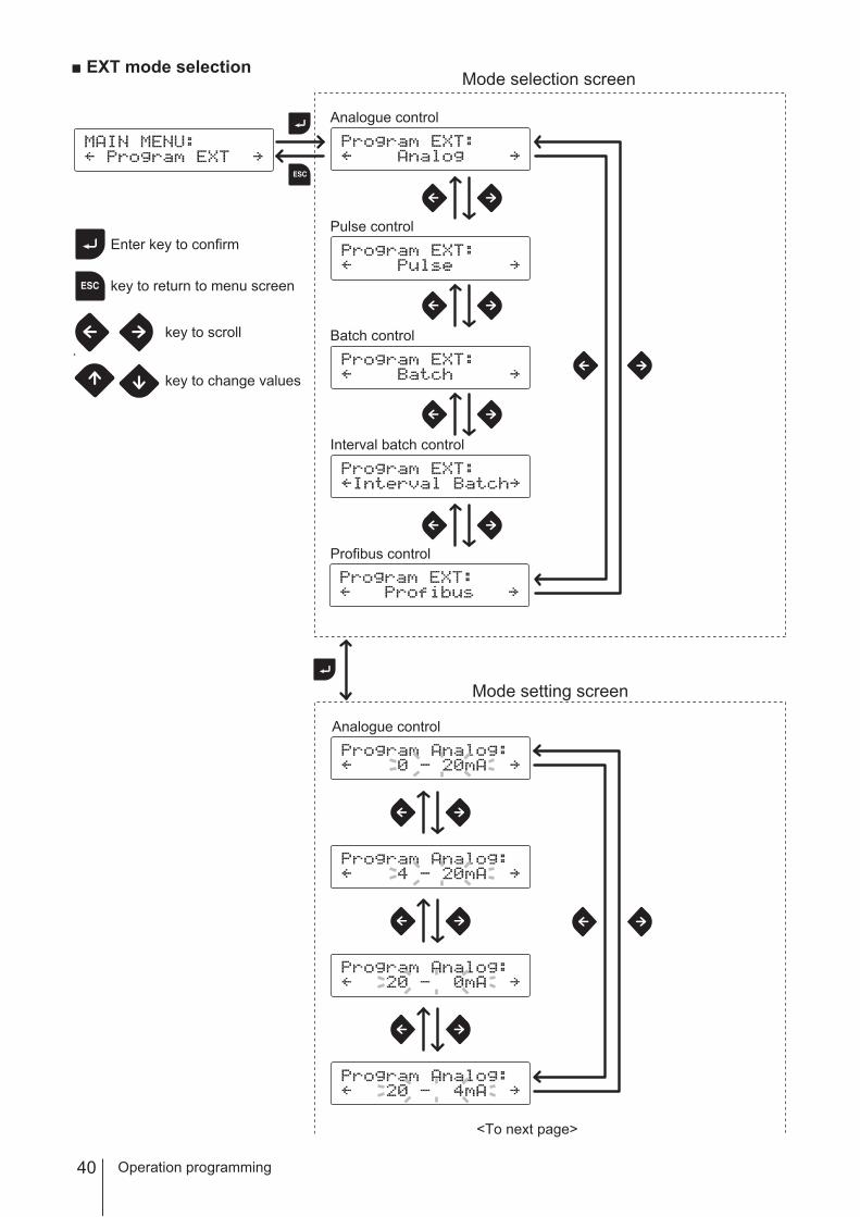
40 Operation programming
Analogue control
Mode setting screen
Enter key to confirm
key to return to menu screen
key to scroll
key to change values
<To next page>
Analogue control
Pulse control
Batch control
Interval batch control
Mode selection screen■ EXT mode selection
Profibus control
41
Operation
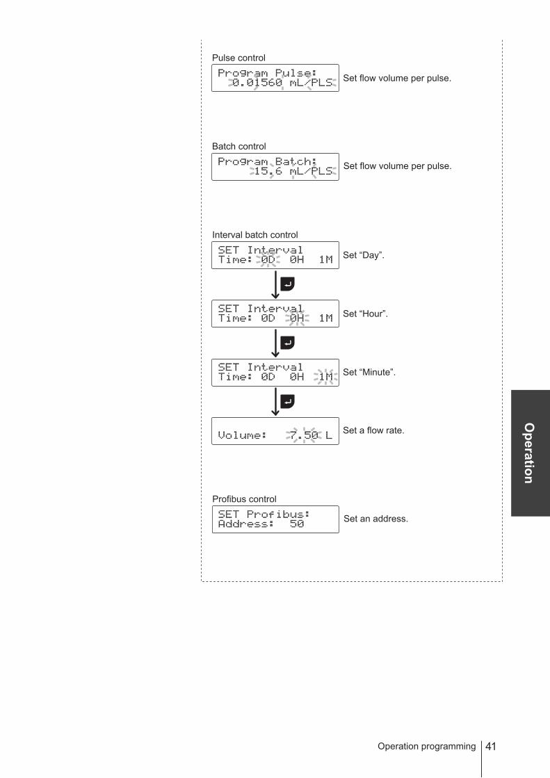
Operation programming
Interval batch control
Set “Day”.
Set “Hour”.
Set “Minute”.
Set a flow rate.
Batch control
Set flow volume per pulse.
Pulse control
Set flow volume per pulse.
Profibus control
Set an address.
42 Operation programming
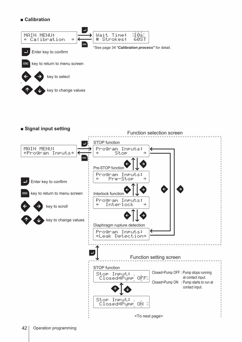
Enter key to confirm
key to return to menu screen
key to select
key to change values
■ Calibration
STOP function
Pre-STOP function
Interlock function
Diaphragm rupture detection
STOP functionClosed=Pump OFF : Pump stops running
at contact input.Closed=Pump ON : Pump starts to run at
contact input.
<To next page>
Enter key to confirm
key to return to menu screen
key to scroll
key to change values
Function setting screen
Function selection screen■ Signal input setting
*See page 34 "Calibration process" for detail.

43
Operation
Operation programming
Pre-STOP functionClosed=Pump OFF : Operation LED lights in
orange at contact input.Closed=Pump ON : Operation LED does not
lights at contact input.
Interlock function
Diaphragm rupture detectionDisable : Rupture detection is not
used.Enable : Rupture detection is used.
Closed=Pump OFF : Pump stops running at contact input.
Closed=Pump ON : Pump starts to run at contact input.

44 Operation programming
Disable : OUT1 does not work asthe STOP function.
Enable : OUT1 works as the STOPfunction.
Output setting screen
Output selection screen
STOP function
Pre-STOP function
Interlock function
Diaphragm rupture detection
STOP function
Pre-STOP function
Interlock function
Overload detection
Disable : OUT1 does not work asthe Interlock function.
Enable : OUT1 works as the Interlockfunction.
Disable : OUT1 does not work asthe Pre-STOP function.
Enable : OUT1 works as the Pre-STOPfunction.
<To next page>
■ Alarm 1 setting : OUT1<Mechanical relay>
Enter key to confirm
key to return to menu screen
key to scroll
key to change values
45
Operation
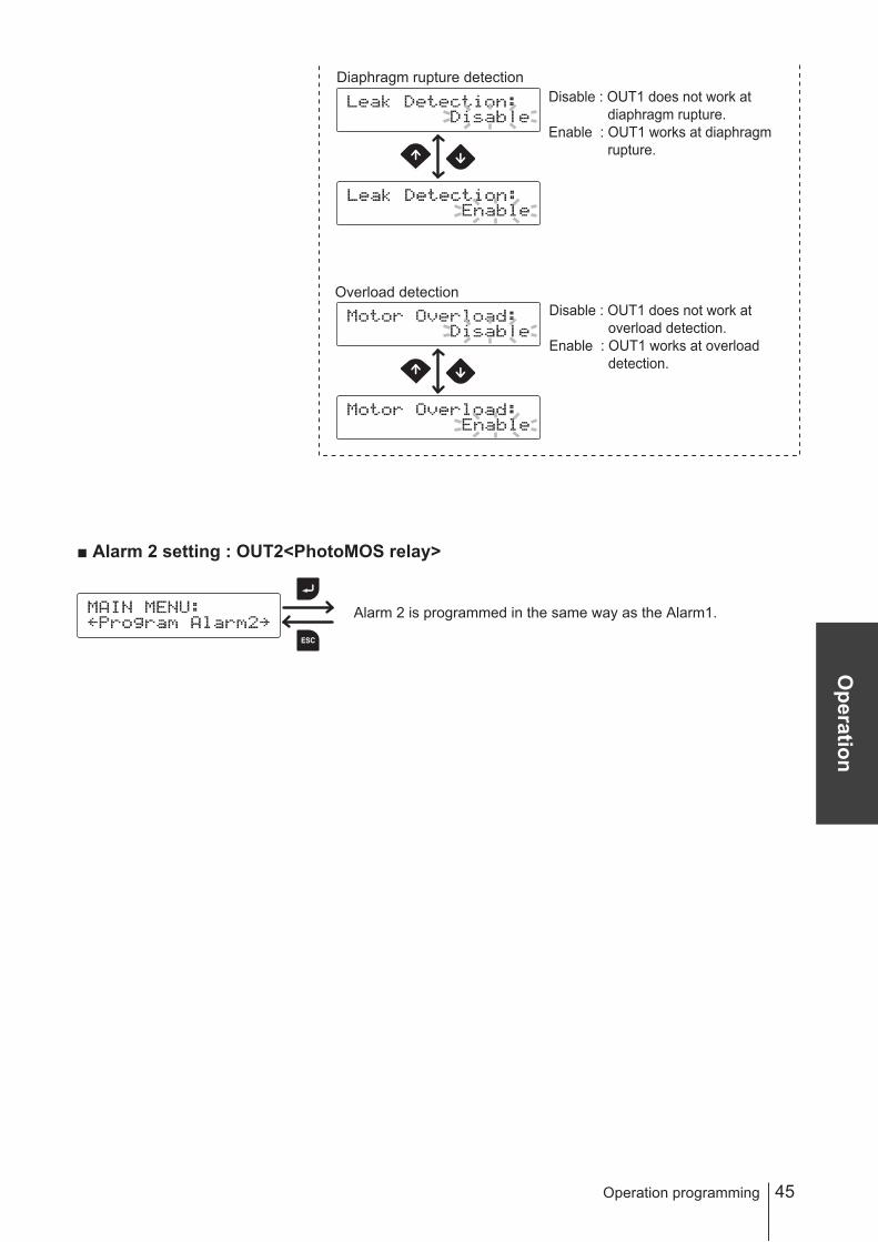
Operation programming
Alarm 2 is programmed in the same way as the Alarm1.
■ Alarm 2 setting : OUT2<PhotoMOS relay>
Diaphragm rupture detection
Overload detection
Disable : OUT1 does not work atdiaphragm rupture.
Enable : OUT1 works at diaphragmrupture.
Disable : OUT1 does not work atoverload detection.
Enable : OUT1 works at overloaddetection.

46
*A selected data will be cleared except the version information.
Operation programming
Operating time
Total flow volume
Powered-on time
Number of ON/OFF
3 sec Return to a previous screen.
Software version
Data logging screen
Enter key to confirm
key to return to menu
key to scroll
Press 3 sec to delete data
■ Data logging

47
Operation
Suction speed
Suction speed
AUX speed
Diaphragm position
Anti chattering
Flow rate unit
Other setting screen
Other selection screen
Enter key to confirm
key to return to menu screen
key to scroll
key to change values
■ Programming of other functions
<To next page>
Language selection
Operation programming
48 Operation programming
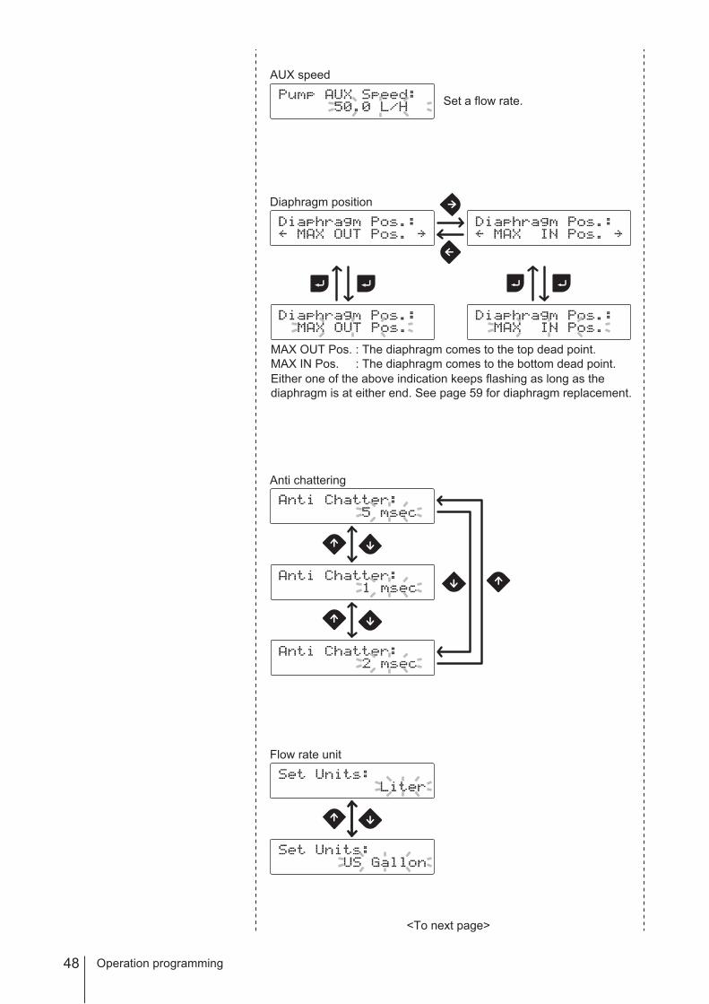
Diaphragm position
MAX OUT Pos. : The diaphragm comes to the top dead point.MAX IN Pos. : The diaphragm comes to the bottom dead point.Either one of the above indication keeps flashing as long as thediaphragm is at either end. See page 59 for diaphragm replacement.
Anti chattering
Flow rate unit
AUX speed
Set a flow rate.
<To next page>

49
Operation
Language selection
Operation programming
50
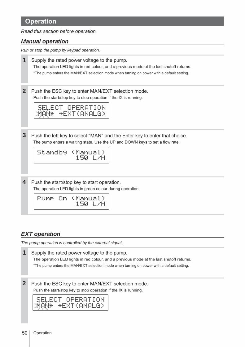
OperationRead this section before operation.
Manual operationRun or stop the pump by keypad operation.
Supply the rated power voltage to the pump.The operation LED lights in red colour, and a previous mode at the last shutoff returns.* The pump enters the MAN/EXT selection mode when turning on power with a default setting.
Push the ESC key to enter MAN/EXT selection mode.Push the start/stop key to stop operation if the IX is running.
Push the left key to select "MAN" and the Enter key to enter that choice.The pump enters a waiting state. Use the UP and DOWN keys to set a flow rate.
Push the start/stop key to start operation.The operation LED lights in green colour during operation.
EXT operationThe pump operation is controlled by the external signal.
Supply the rated power voltage to the pump.The operation LED lights in red colour, and a previous mode at the last shutoff returns.* The pump enters the MAN/EXT selection mode when turning on power with a default setting.
Push the ESC key to enter MAN/EXT selection mode.Push the start/stop key to stop operation if the IX is running.
Operation
2
1
3
4
2
1
51
Operation
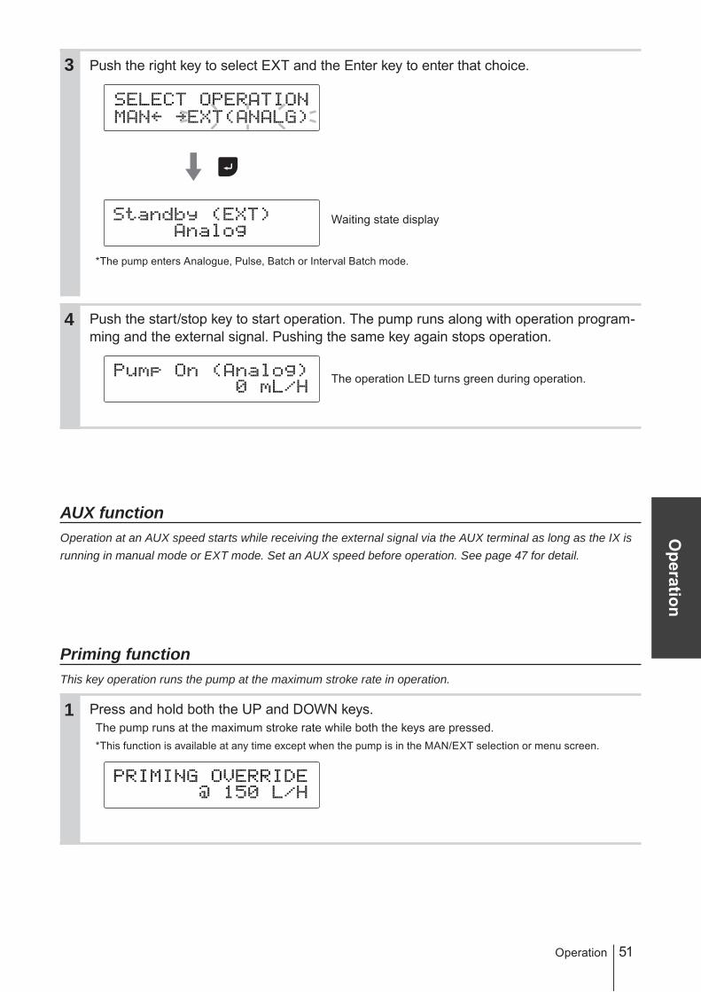
Push the right key to select EXT and the Enter key to enter that choice.
Waiting state display
*The pump enters Analogue, Pulse, Batch or Interval Batch mode.
Push the start/stop key to start operation. The pump runs along with operation program-ming and the external signal. Pushing the same key again stops operation.
The operation LED turns green during operation.
AUX functionOperation at an AUX speed starts while receiving the external signal via the AUX terminal as long as the IX is running in manual mode or EXT mode. Set an AUX speed before operation. See page 47 for detail.
Priming functionThis key operation runs the pump at the maximum stroke rate in operation.
Press and hold both the UP and DOWN keys.The pump runs at the maximum stroke rate while both the keys are pressed.* This function is available at any time except when the pump is in the MAN/EXT selection or menu screen.
1
Operation
3
4

52
Keypad lockKeypad lock can be active for the prevention of erroneous key operation.NOTE• Any key operation is not acceptable when the keypad lock is active. In an emergency, pressing the start/stop
key for two seconds, the pump enters a wait state and stops running. Release this state to resume operation.• This function is available in MAN/EXT selection, a wait state or operation.
■ Keypad lock activation
Press and hold both the right and left keys for 3 seconds.
3 sec
"KEY LOCKED!" appears on the screen for one second.
* This indication comes up every time any key is pushed.
■ Keypad lock release
Press and hold the ESC key for 2 seconds.
2 sec
"KEY LOCKED!" first appears on the screen and then changes to "KEY UNLOCKED!".
■ Emergency stop
Press and hold the start/stop key for 2 seconds to stop the pump.Release the keypad lock state to resume operation.
Operation
1
1
1
53
Maintenance
Maintenance
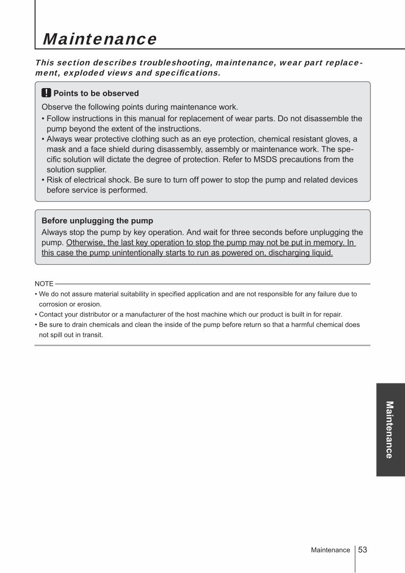
This section describes troubleshooting, maintenance, wear part replace-ment, exploded views and specifications.
Points to be observedObserve the following points during maintenance work.• Follow instructions in this manual for replacement of wear parts. Do not disassemble the
pump beyond the extent of the instructions.• Always wear protective clothing such as an eye protection, chemical resistant gloves, a
mask and a face shield during disassembly, assembly or maintenance work. The spe-cific solution will dictate the degree of protection. Refer to MSDS precautions from the solution supplier.
• Risk of electrical shock. Be sure to turn off power to stop the pump and related devices before service is performed.
Before unplugging the pumpAlways stop the pump by key operation. And wait for three seconds before unplugging the pump. Otherwise, the last key operation to stop the pump may not be put in memory. In this case the pump unintentionally starts to run as powered on, discharging liquid.
NOTE• We do not assure material suitability in specified application and are not responsible for any failure due to
corrosion or erosion.• Contact your distributor or a manufacturer of the host machine which our product is built in for repair.• Be sure to drain chemicals and clean the inside of the pump before return so that a harmful chemical does
not spill out in transit.
Maintenance

54 Troubleshooting
TroubleshootingFirst check the following points. If the following measures do not help remove problems, con-tact your nearest distributor.
■ PumpStates Possible causes Solutions
The pump does not run ( The operation LED does not light or the screen is blank.).
Power voltage is too low. • Observe the allowable voltage range of 90-264VAC.
The pump is not powered. • Check the pump is switched on.• Correct wiring.• Replace a breaking wire to new one.
Liquid can not be pumped up.
Air lock in the pump • Expel air. See page 33.
Air ingress through a suction line • Reroute piping.
An O ring is not fitted to a valve set. • Fit O ring to the valve set.
Foreign matters are stuck in the pump head valves.
• Dismantle, inspect and clean the valves. Replace as necessary.
A ball valve is stuck on a valve seat. • Dismantle, inspect and clean the valve. Replace as necessary.
A vale seat has been pressed in the valve guide.
• Do not push the valve seat into the valve guide. See page 59.
A flow rate fluctuates. Air stays in the pump head. • Expel air. See page 33.
Overfeeding occurs. • Mount a back pressure valve to keep a constant level of discharge line pressure.
Foreign matters are stuck in the pump head valves.
• Dismantle, inspect and clean the valves. Replace as necessary.
Diaphragm is broken. • Replace the diaphragm. See page 59.
Pressure fluctuates at an injection point.
• Maintain a pressure constant at an injec-tion point by optimizing piping or by relo-cating the point.
Liquid leaks. A fitting is loose. • Tighten the nut to fix the fitting.
Loose fit of the pump head • Retighten the pump head. See page 32.
An O ring is not fitted to a valve set. • Fit O ring to the valve set. See page 58.
Diaphragm is broken.A leak from the drain port (Vent hole)
• Replace the diaphragm. See page 59.
55
Maintenance
Inspection
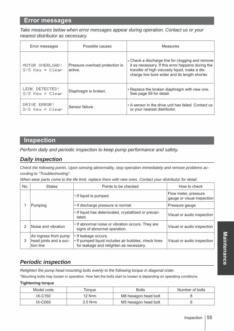
Error messagesTake measures below when error messages appear during operation. Contact us or your nearest distributor as necessary.
Error messages Possible causes Measures
Pressure overload protection is active.
• Check a discharge line for clogging and remove it as necessary. If this error happens during the transfer of high viscosity liquid, make a dis-charge line bore wider and its length shorter.
Diaphragm is broken. • Replace the broken diaphragm with new one. See page 59 for detail.
Sensor failure • A sensor in the drive unit has failed. Contact us or your nearest distributor.
InspectionPerform daily and periodic inspection to keep pump performance and safety.
Daily inspectionCheck the following points. Upon sensing abnormality, stop operation immediately and remove problems ac-cording to "Troubleshooting".When wear parts come to the life limit, replace them with new ones. Contact your distributor for detail.
No. States Points to be checked How to check
1 Pumping
• If liquid is pumped. Flow meter, pressure gauge or visual inspection
• If discharge pressure is normal. Pressure gauge
• If liquid has deteriorated, crystallized or precipi-tated. Visual or audio inspection
2 Noise and vibration • If abnormal noise or vibration occurs. They are signs of abnormal operation. Visual or audio inspection
3Air ingress from pump head joints and a suc-tion line
• If leakage occurs.• If pumped liquid includes air bubbles, check lines
for leakage and retighten as necessary.Visual or audio inspection
Periodic inspectionRetighten the pump head mounting bolts evenly to the following torque in diagonal order.* Mounting bolts may loosen in operation. How fast the bolts start to loosen is depending on operating conditions.
Tightening torque
Model code Torque Bolts Number of boltsIX-C150 12 N•m M8 hexagon head bolt 8IX-C060 3.5 N•m M5 hexagon head bolt 6

56 Wear part replacement
Wear part replacementTo run the pump for a long period, wear parts need to be replaced periodically.It is recommended that the following parts are always stocked for immediate replacement. Contact your nearest distributor for detail.
Precautions• Solution in the discharge line may be under pressure. Release the pressure from the dis-
charge line before disconnecting plumbing or disassembly of the pump to avoid solution spray.• Rinse wet ends thoroughly with tap water.• Each time the pump head is dismantled, replace the diaphragm and the valve sets with
new ones.
Wear part list
Pump head Parts # of parts Estimated life
C150
Valve set(TC type)
Discharge sideIX0021
Suction sideIX0022
2 sets 8000 hours
Valve set(TE type)
Discharge sideIX0034
Suction sideIX0033
2 sets 8000 hours
Valve set(S6 type)IX0032
2 sets 8000 hours
Diaphragm 1 4000 hours
10(IX0027)
3(IX0025)
2(IX0024)
10(IX0027)
4(IX0026)
10(IX0027)
Discharge side
Suction side
7(IX0007)
3(IX0003)
2(IX0002)
4(IX0004)
8(IX0008)
5(IX0005)
7(IX0007)
6(IX0006)
30(IX0014)
Discharge side
Suction side
7(IX0038)
3(IX0003)
2(IX0002)
4(IX0037)
8(IX0039)
5(IX0005)
7(IX0007)
6(IX0006)
57
Maintenance
Wear part replacement
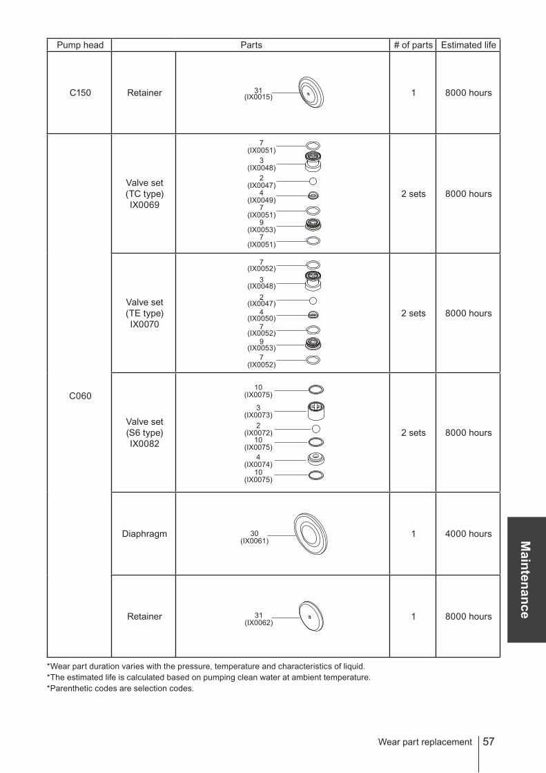
Pump head Parts # of parts Estimated life
C150 Retainer 1 8000 hours
C060
Valve set(TC type)IX0069
2 sets 8000 hours
Valve set(TE type)IX0070
2 sets 8000 hours
Valve set(S6 type)IX0082
2 sets 8000 hours
Diaphragm 1 4000 hours
Retainer 1 8000 hours
* Wear part duration varies with the pressure, temperature and characteristics of liquid.* The estimated life is calculated based on pumping clean water at ambient temperature.* Parenthetic codes are selection codes.
31(IX0015)
7(IX0051)
3(IX0048)
2(IX0047)
4(IX0049)
7(IX0051)
9(IX0053)
7(IX0051)
10(IX0075)
3(IX0073)
2(IX0072)
10(IX0075)
4(IX0074)
10(IX0075)
30(IX0061)
31(IX0062)
7(IX0052)
3(IX0048)
2(IX0047)
4(IX0050)
7(IX0052)
9(IX0053)
7(IX0052)

58
Before replacement
Stop pump operation.
Close the suction line.
Open the drain valve to release liquid out of the discharge line.
NOTEOpen the valve gradually. Chemicals may be purged if the discharge line pressure maintains higher pressure than atmos-pheric pressure.
Valve set replacement
Remove pipes from the pump.NOTE• Be careful not to get wet with residual chemicals in piping.• Rinse off chemicals or crystals as necessary.• The valve set may come down as the suction pipe is removed. Take care not to drop it.• Remove the IX-C060 TC/TE nuts while holding the adapter with a spanner.
IX-C150 TC/TE IX-C060 TC/TE IX-C150 S6 IX-C060 S6
Close
2
1
3
1
Open
Drain valve
Wear part replacement
NutAdapter Remove
the bolt.Remove thevalve cap.
Nut
59
Maintenance
Wear part replacement
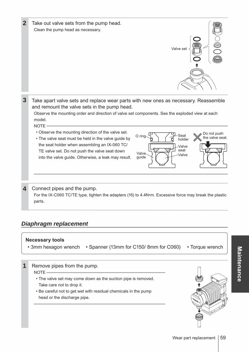
Take out valve sets from the pump head.Clean the pump head as necessary.
Take apart valve sets and replace wear parts with new ones as necessary. Reassemble and remount the valve sets in the pump head.Observe the mounting order and direction of valve set components. See the exploded view at each model.NOTE• Observe the mounting direction of the valve set.• The valve seat must be held in the valve guide by
the seat holder when assembling an IX-060 TC/TE valve set. Do not push the valve seat down into the valve guide. Otherwise, a leak may result.
Connect pipes and the pump.For the IX-C060 TC/TE type, tighten the adapters (16) to 4.4N•m. Excessive force may break the plastic parts.
Diaphragm replacement
Necessary tools• 3mm hexagon wrench • Spanner (13mm for C150/ 8mm for C060) • Torque wrench
Remove pipes from the pump.NOTE• The valve set may come down as the suction pipe is removed.
Take care not to drop it.• Be careful not to get wet with residual chemicals in the pump
head or the discharge pipe.
1
3
4
2
Valve set
Valveguide
Seat holder
ValveseatValve
O ringDo not pushthe valve seat.
60
2
Hexagon wrench
Bolt cover
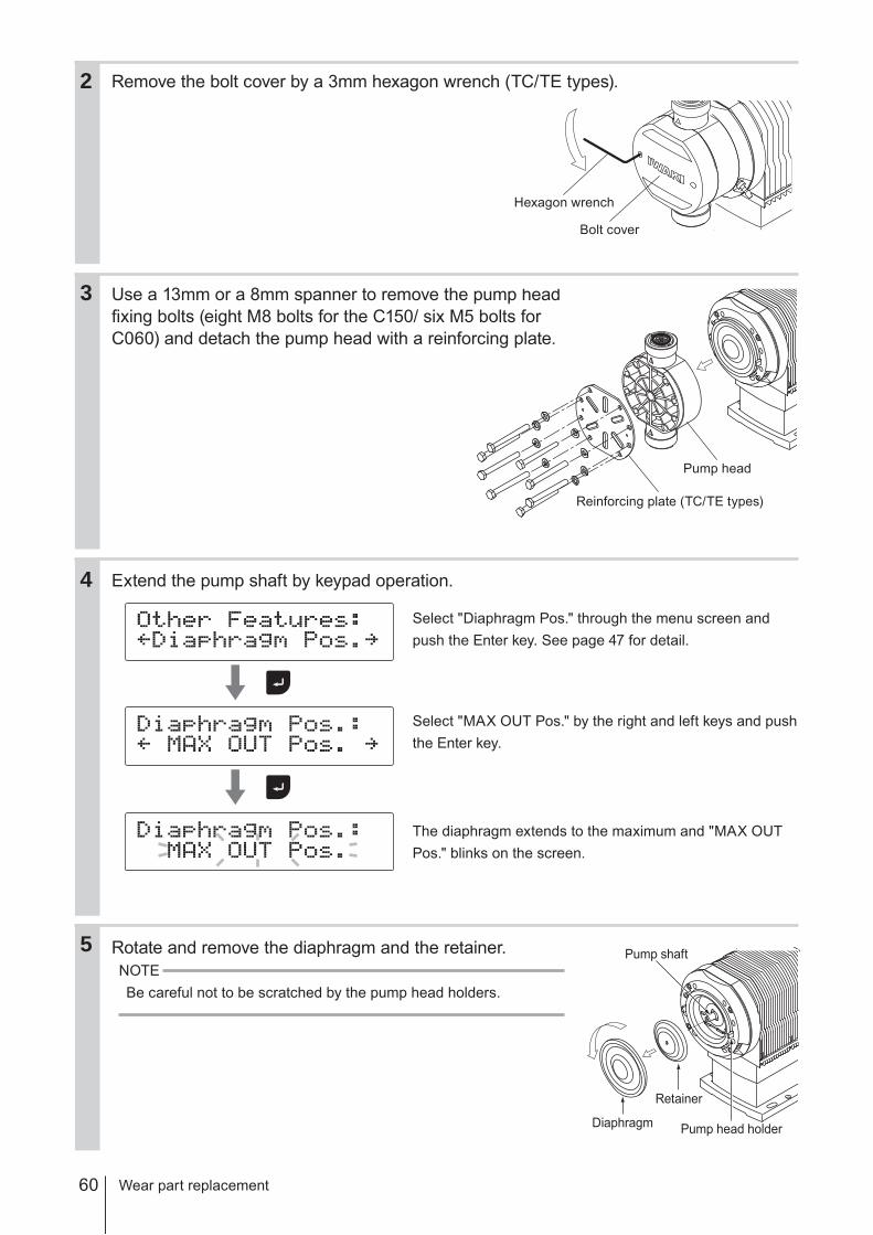
Remove the bolt cover by a 3mm hexagon wrench (TC/TE types).
Use a 13mm or a 8mm spanner to remove the pump head fixing bolts (eight M8 bolts for the C150/ six M5 bolts for C060) and detach the pump head with a reinforcing plate.
Extend the pump shaft by keypad operation.
Select "Diaphragm Pos." through the menu screen and push the Enter key. See page 47 for detail.
Select "MAX OUT Pos." by the right and left keys and push the Enter key.
The diaphragm extends to the maximum and "MAX OUT Pos." blinks on the screen.
Rotate and remove the diaphragm and the retainer.NOTEBe careful not to be scratched by the pump head holders.
Wear part replacement
5
4
Reinforcing plate (TC/TE types)
Pump head
3
Pump shaft
Diaphragm
Retainer
Pump head holder

61
Maintenance
Clean the retainer or replace it with a new one. Apply grease (Dow Corning Toray MO-LYKOTE® HP-500) on its surface and screw burning protective agent to the shaft of a new diaphragm.
Fit a new diaphragm and the retainer into the pump shaft.Slide the retainer, dome end first, onto the diaphragm shaft. And then screw the shaft into the pump shaft and tighten it until bottoms out and will not turn further.NOTEIf it is fitted loose, failure may result.
Retract the pump shaft by keypad operation.
Push the Enter key.
Select "Diaphragm Pos." and push the Enter key.
Select "MAX IN Pos." by the right and left keys.
Push the Enter key.
The diaphragm contracts and "MAX IN Pos." flashes.
Mount the pump head.Tighten the bolts evenly to 12N•m for the C150 or 3.5N•m for the C060 in diagonal order.NOTECheck the pump shaft has contracted to the full before mounting the pump head, or a leak or damage may result.
Wear part replacement
6
7
8
9
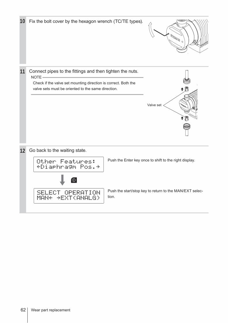
62
10 Fix the bolt cover by the hexagon wrench (TC/TE types).
Connect pipes to the fittings and then tighten the nuts.NOTECheck if the valve set mounting direction is correct. Both the valve sets must be oriented to the same direction.
Go back to the waiting state.
Push the Enter key once to shift to the right display.
Push the start/stop key to return to the MAN/EXT selec-tion.
Wear part replacement
11
12
Valve set
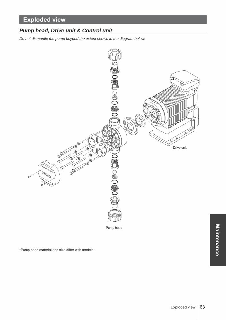
63
Maintenance
Exploded view
Pump head, Drive unit & Control unitDo not dismantle the pump beyond the extent shown in the diagram below.
*Pump head material and size differ with models.
Exploded view
Drive unit
Pump head
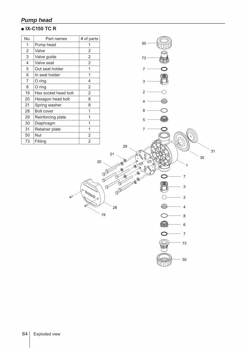
64
Pump head■ IX-C150 TC R
No. Part names # of parts1 Pump head 12 Valve 23 Valve guide 24 Valve seat 25 Out seat holder 16 In seat holder 17 O ring 48 O ring 219 Hex socket head bolt 220 Hexagon head bolt 821 Spring washer 828 Bolt cover 129 Reinforcing plate 130 Diaphragm 131 Retainer plate 150 Nut 273 Fitting 2
Exploded view
1
30
31
19
28
20
21
29
50
50
73
7
3
2
4
8
5
7
73
7
7
6
3
2
4
8
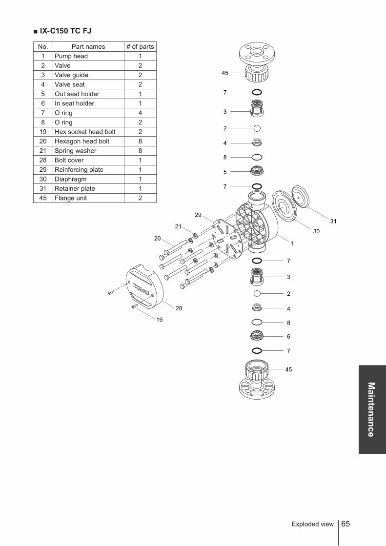
65
Maintenance
■ IX-C150 TC FJ
No. Part names # of parts1 Pump head 12 Valve 23 Valve guide 24 Valve seat 25 Out seat holder 16 In seat holder 17 O ring 48 O ring 219 Hex socket head bolt 220 Hexagon head bolt 821 Spring washer 828 Bolt cover 129 Reinforcing plate 130 Diaphragm 131 Retainer plate 145 Flange unit 2
Exploded view
1
30
31
19
28
20
21
29
45
45
7
3
2
4
8
5
7
7
7
6
3
2
4
8

66
■ IX-C150 S6 R
No. Part names # of parts1 Pump head 12 Valve 23 Valve guide 24 Valve seat 210 Valve gasket 620 Hexagon head bolt 821 Spring washer 830 Diaphragm 131 Retainer plate 155 Setting flange 273 Fitting 283 Hexagon head bolt 8
1
30
3120
21
55
73
10
3
2
4
10
10
10
3
4
10
10
2
83
55
73
83
Exploded view
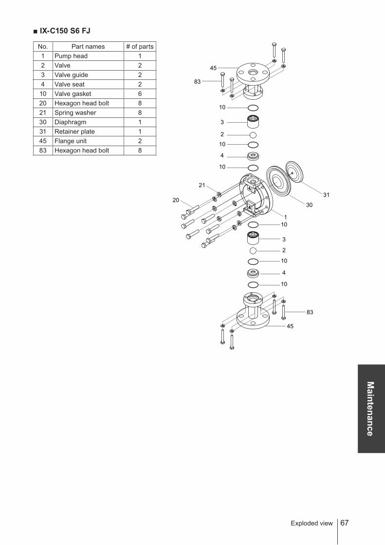
67
Maintenance
■ IX-C150 S6 FJ
No. Part names # of parts1 Pump head 12 Valve 23 Valve guide 24 Valve seat 210 Valve gasket 620 Hexagon head bolt 821 Spring washer 830 Diaphragm 131 Retainer plate 145 Flange unit 283 Hexagon head bolt 8
1
30
3120
21
45
83
10
3
2
4
10
10
10
3
4
10
10
2
83
45
Exploded view
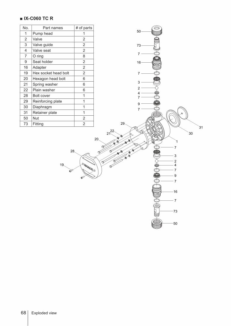
68
■ IX-C060 TC R
No. Part names # of parts1 Pump head 12 Valve 23 Valve guide 24 Valve seat 27 O ring 89 Seat holder 216 Adapter 219 Hex socket head bolt 220 Hexagon head bolt 621 Spring washer 622 Plain washer 628 Bolt cover 129 Reinforcing plate 130 Diaphragm 131 Retainer plate 150 Nut 273 Fitting 2
1
30
31
20
22
3
9
47
2
73
50
7
7
7
16
3
9
4
7
2
73
50
7
7
7
16
19
29
28
21
Exploded view

69
Maintenance
■ IX-C060 TC FJ
No. Part names # of parts1 Pump head 12 Valve 23 Valve guide 24 Valve seat 27 O ring 89 Seat holder 216 Adapter 219 Hex socket head bolt 220 Hexagon head bolt 621 Spring washer 622 Plain washer 628 Bolt cover 129 Reinforcing plate 130 Diaphragm 131 Retainer plate 145 Flange unit 2
1
30
31
45
7
7
16
324
9
7
7
50
45
7
7
16
324
9
7
7
50
20
22
19
29
28
21
Exploded view
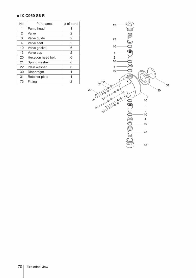
70
■ IX-C060 S6 R
No. Part names # of parts1 Pump head 12 Valve 23 Valve guide 24 Valve seat 210 Valve gasket 613 Valve cap 220 Hexagon head bolt 621 Spring washer 622 Plain washer 630 Diaphragm 131 Retainer plate 173 Fitting 2
1
30
3120
22
10
3
410
102
13
73
10
3
4
10
10
2
13
73
21
Exploded view
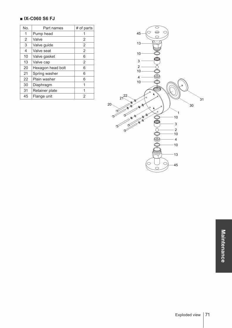
71
Maintenance
■ IX-C060 S6 FJ
No. Part names # of parts1 Pump head 12 Valve 23 Valve guide 24 Valve seat 210 Valve gasket 613 Valve cap 220 Hexagon head bolt 621 Spring washer 622 Plain washer 630 Diaphragm 131 Retainer plate 145 Flange unit 2
1
30
3120
22
10
3
410
102
13
45
10
3
4
10
10
2
13
45
21
Exploded view

72
Specifications/Outer dimensionsSpecificationsInformation in this section is subject to change without notice.■ Pump
Model code Flow rateL/H
Discharge pressure
MPa
Power con-sumption
W
Current value
AConnection Weight
kg
IX-C150 TC/TER
0.2-150 0.4
62 0.8
R3/49
FJ JIS10K20A
IX-C150 S6R R3/4 11FJ JIS10K20A 13
IX-C060 TC/TER
0.08-60 1.0
R1/29
FJ JIS10K15A
IX-C060 S6R R1/2 11FJ JIS10K15A 12
*The above information is based on pumping clean water at rated voltage and ambient temperature.* Pressure overload protection will stop operation when a discharge pressure has risen 1.5 to 2 times higher than the maxi-mum level.
*Allowable room temperature: 0-50°C*Allowable liquid temperature: 0-50°C (TC/TE), 0-80°C (S6)*Allowable power voltage deviation: Within ±10% of the rated range*Ambient humidity: 30-90%RH (Non condensing)* When running the IX-C150 S6 at or below 1L/H or the IX-C060 S6 at or below 0.4L/H, an actual flow rate may not meet a target rate.
* Noise level: 70dB(A) for the TC and TE types and 80dB(A) for the S6 type.
■ European power cableConduction section area 0.75 [mm2] Triplex cable (L/N/PE)
Length 2000 [mm]Standard H03VV-F
Terminal treatment European plug
■ Australian power cableConduction section area 1.0 [mm2] Triplex cable (L/N/E)
Length 2000 [mm]Standard H05VV-F AS3191
Terminal treatment Australian plug
■ Body colourBlue Munsell colour system 7.5PB 3/8
Specifications/Outer dimensions
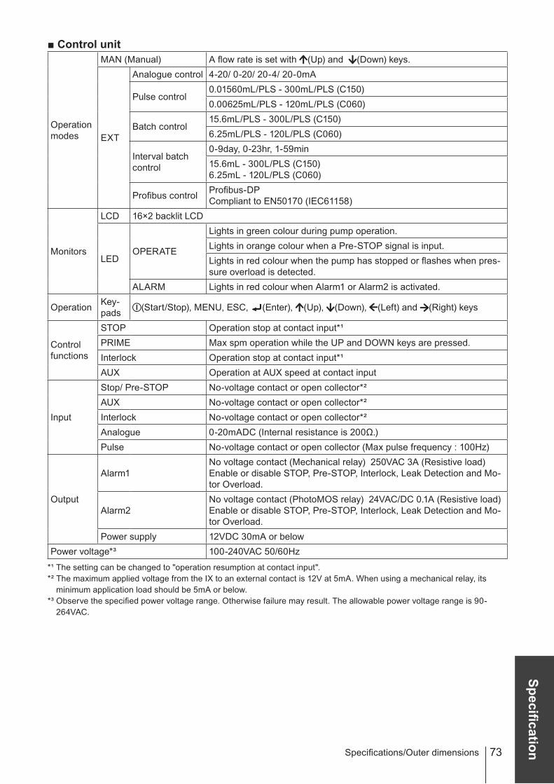
73
Specification
■ Control unit
Operation modes
MAN (Manual) A flow rate is set with (Up) and (Down) keys.
EXT
Analogue control 4-20/ 0-20/ 20-4/ 20-0mA
Pulse control0.01560mL/PLS - 300mL/PLS (C150)0.00625mL/PLS - 120mL/PLS (C060)
Batch control15.6mL/PLS - 300L/PLS (C150)6.25mL/PLS - 120L/PLS (C060)
Interval batch control
0-9day, 0-23hr, 1-59min15.6mL - 300L/PLS (C150)6.25mL - 120L/PLS (C060)
Profibus control Profibus-DPCompliant to EN50170 (IEC61158)
Monitors
LCD 16×2 backlit LCD
LEDOPERATE
Lights in green colour during pump operation.Lights in orange colour when a Pre-STOP signal is input.Lights in red colour when the pump has stopped or flashes when pres-sure overload is detected.
ALARM Lights in red colour when Alarm1 or Alarm2 is activated.
Operation Key-pads (Start/Stop), MENU, ESC, (Enter), (Up), (Down), (Left) and (Right) keys
Control functions
STOP Operation stop at contact input*¹PRIME Max spm operation while the UP and DOWN keys are pressed.Interlock Operation stop at contact input*¹AUX Operation at AUX speed at contact input
Input
Stop/ Pre-STOP No-voltage contact or open collector*²AUX No-voltage contact or open collector*²Interlock No-voltage contact or open collector*²Analogue 0-20mADC (Internal resistance is 200Ω.)Pulse No-voltage contact or open collector (Max pulse frequency : 100Hz)
Output
Alarm1No voltage contact (Mechanical relay) 250VAC 3A (Resistive load)Enable or disable STOP, Pre-STOP, Interlock, Leak Detection and Mo-tor Overload.
Alarm2No voltage contact (PhotoMOS relay) 24VAC/DC 0.1A (Resistive load)Enable or disable STOP, Pre-STOP, Interlock, Leak Detection and Mo-tor Overload.
Power supply 12VDC 30mA or belowPower voltage*³ 100-240VAC 50/60Hz
*¹ The setting can be changed to "operation resumption at contact input".*² The maximum applied voltage from the IX to an external contact is 12V at 5mA. When using a mechanical relay, its
minimum application load should be 5mA or below.*³ Observe the specified power voltage range. Otherwise failure may result. The allowable power voltage range is 90-
264VAC.
Specifications/Outer dimensions
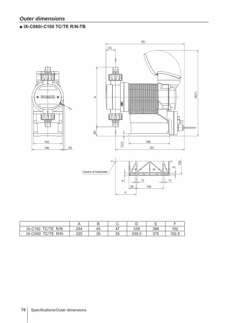
74 Specifications/Outer dimensions
Outer dimensions■ IX-C060/-C150 TC/TE R/N-TB
A B C D E FIX-C150 TC/TE R/N 294 45 47 339 386 102IX-C060 TC/TE R/N 325 30 35 339.5 375 102.5
135
11 1112
6
9
199
(B)
142
156 (5)
9
(C)
(E)
(421
)
(D)
F
35
13.5
A
Centre of inlet/lutlet

75
SpecificationSpecifications/Outer dimensions
■ IX-C060/-C150 TC/TE FJ/FD/FA-TB
A B C D E FIX-C150 TC/TE FJ/FD/FA 317 34 ─ 339 ─ 102IX-C060 TC/TE FJ/FD/FA 335 25 ─ 339.5 ─ 102.5
135
11 11
126
9
199
9
(421
)
(D)
F
35
13.5
(B)
A
Centre of inlet/lutlet
142
156 (5)

76
■ IX-C060/-C150 TC/TE R/N-RF
A B C D E FIX-C150 TC/TE R/N 294 45 47 339 386 102IX-C060 TC/TE R/N 325 30 35 339.5 375 102.5
199
A(B
)
(C)
(E)
(D)13.5
135
11 11
126
9
9
F
35
Centre of inlet/lutlet
142
156
(115)
Specifications/Outer dimensions

77
Specification
■ IX-C060/-C150 TC/TE FJ/FD/FA-RF
A B C D E FIX-C150 TC/TE FJ/FD/FA 317 34 ─ 339 ─ 102IX-C060 TC/TE FJ/FD/FA 335 25 ─ 339.5 ─ 102.5
199
(D)13.5
135
11 11
126
9
9
F
35
Centre of inlet/lutlet
(B)
A
142
156
(115)
Specifications/Outer dimensions
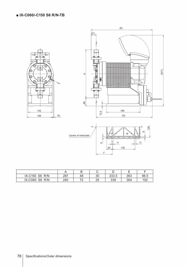
78
■ IX-C060/-C150 S6 R/N-TB
A B C D E FIX-C150 S6 R/N 287 48 30 333.5 363 96.5IX-C060 S6 R/N 240 72 25 339 364 102
135
11 11
126
9
199
(B)
9
(C)
(E)
(421
)
(D)
F
35
13.5
A
Centre of inlet/lutlet
142
156 (5)
Specifications/Outer dimensions
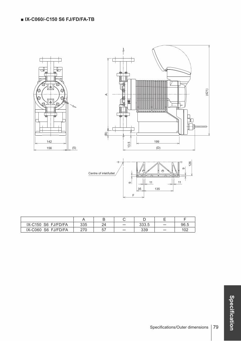
79
Specification
■ IX-C060/-C150 S6 FJ/FD/FA-TB
A B C D E FIX-C150 S6 FJ/FD/FA 335 24 ─ 333.5 ─ 96.5IX-C060 S6 FJ/FD/FA 270 57 ─ 339 ─ 102
135
11 11
126
9
199
9
(421
)
(D)
F
35
13.5
Centre of inlet/lutlet
(B)
A
142
156 (5)
Specifications/Outer dimensions
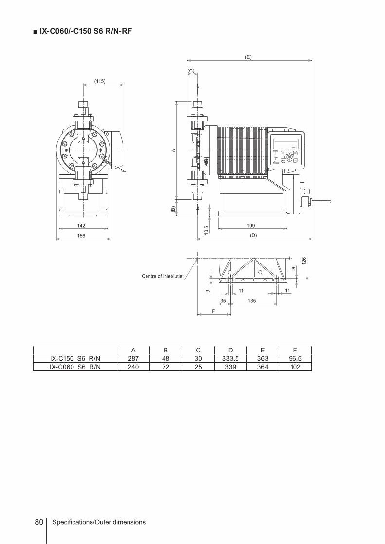
80
■ IX-C060/-C150 S6 R/N-RF
A B C D E FIX-C150 S6 R/N 287 48 30 333.5 363 96.5IX-C060 S6 R/N 240 72 25 339 364 102
142
156
(115)
199
(C)
(D)13.5
135
11 11
126
9
9
F
35
A(B
)
(E)
Centre of inlet/lutlet
Specifications/Outer dimensions

81
Specification
■ IX-C060/-C150 S6 FJ/FD/FA-RF
A B C D E FIX-C150 S6 FJ/FD/FA 335 24 ─ 333.5 ─ 96.5IX-C060 S6 FJ/FD/FA 270 57 ─ 339 ─ 102
199
(D)13.5
135
11 11
126
9
9
F
35
A(B
)
Centre of inlet/lutlet
142
156
(115)
Specifications/Outer dimensions

82

83

( )Country codes
IWAKI CO.,LTD. 6-6 Kanda-Sudacho 2-chome Chiyoda-ku Tokyo 101-8558 JapanTEL:(81)3 3254 2935 FAX:3 3252 8892
Australia IWAKI Pumps Australia Pty. Ltd. TEL : (61)2 9899 2411 FAX : 2 9899 2421 Italy IWAKI Italia S.R.L. TEL : (39)0444 371115 FAX : 0444 335350Austria IWAKI EUROPE GmbH TEL : (49)2154 9254 0 FAX : 2154 9254 48 Korea IWAKI Korea Co.,Ltd. TEL : (82)2 2630 4800 FAX : 2 2630 4801Belgium IWAKI Belgium n.v. TEL : (32)1367 0200 FAX : 1367 2030 Malaysia IWAKIm Sdn. Bhd. TEL : (60)3 7803 8807 FAX : 3 7803 4800China IWAKI Pumps (Shanghai) Co., Ltd. TEL : (86)21 6272 7502 FAX : 21 6272 6929 Norway IWAKI Norge AS TEL : (47)23 38 49 00 FAX : 23 38 49 01China IWAKI Pumps (Guangdong) Co., Ltd. TEL : (86)750 3866228 FAX : 750 3866278 Singapore IWAKI Singapore Pte. Ltd. TEL : (65)6316 2028 FAX : 6316 3221China GFTZ IWAKI Engineering & Trading (Guangzhou) TEL : (86)20 8435 0603 FAX : 20 8435 9181 Spain IWAKI Iberica Pumps, S.A. TEL : (34)943 630030 FAX : 943 628799China GFTZ IWAKI Engineering & Trading (Beijing) TEL : (86)10 6442 7713 FAX : 10 6442 7712 Sweden IWAKI Sverige AB TEL : (46)8 511 72900 FAX : 8 511 72922Denmark IWAKI Nordic A/S TEL : (45)48 24 2345 FAX : 48 24 2346 Switzerland IWAKI (Schweiz) AG TEL : (41)26 674 9300 FAX : 26 674 9302Finland IWAKI Suomi Oy TEL : (358)9 2745810 FAX : 9 2742715 Taiwan IWAKI Pumps Taiwan Co., Ltd. TEL : (886)2 8227 6900 FAX : 2 8227 6818France IWAKI France S.A. TEL : (33)1 69 63 33 70 FAX : 1 64 49 92 73 Taiwan IWAKI Pumps Taiwan (Hsin-chu) Co., Ltd. TEL : (886)3 573 5797 FAX : (886)3 573 5798Germany IWAKI EUROPE GmbH TEL : (49)2154 9254 0 FAX : 2154 9254 48 Thailand IWAKI (Thailand) Co.,Ltd. TEL : (66)2 322 2471 FAX : 2 322 2477Holland IWAKI EUROPE NL Branch TEL : (31)547 293 160 FAX : 547 292 332 U.K. IWAKI Pumps (UK) LTD. TEL : (44)1743 231363 FAX : 1743 366507Hong Kong IWAKI Pumps Co., Ltd. TEL : (852)2 607 1168 FAX : 2 607 1000 U.S.A. IWAKI AMERICA Inc. TEL : (1)508 429 1440 FAX : 508 429 1386Indonesia IWAKI Singapore (Indonesia Branch) TEL : (62)21 690 6606 FAX : 21 690 6612 Vietnam IWAKI pumps Vietnam Co.,Ltd. TEL : (84)613 933456 FAX : 613 933399
T706-4 '12/02
Top Related