


Languages
Pages
Legal


Technical Data
iTRAK SystemBulletin 2198T
Topic Page
About the iTRAK System 3
Hardware Configuration 4
Design Considerations 11
iTRAK System Track 17
Motor Module 18
Movers 25
TriMax Bearing Rails 40
TriMax Mover Replacement Components 43
TriMax Tools 45
Lubrication System 47
Magnet Plates 50
Position Magnets 56
Gateway 57
Kinetix 5700 iTRAK Power Supply and iTRAK Bus Conditioner Module 65
Power Cable - iTRAK Power Supply 70
Communication Cables 71
Mounting Options 72
Mover and Magnet Plate Specifications 73
Environmental Specifications 74
Certifications 74
Performance Specifications 75
Force Speed Curves 76
Additional Resources 80

iTRAK System
Summary of Changes
This manual contains new and updated information as indicated in this table.
This publication provides catalog numbers and product specifications, including performance, environmental, certifications, load force, and dimension drawings for the iTRAK® system and components.
Use this publication with the Kinetix® Motion Control Selection Guide, publication KNX-SG001, to help you decide on the motion-control product families that are best suited for your system requirements.
Topic Page
Corrected catalog numbers 30…38
Updated TriMax Alignment Tool Kit components 46
Corrected magnet plate drawings to show series B hole locations 55…59
Corrected magnet plate weights 55
2 Rockwell Automation Publication 2189T-TD001F-EN-P - April 2018

iTRAK System
About the iTRAK System
The iTRAK System is a highly flexible and innovative linear-motion solution with independent control of multiple movers using Studio 5000 Logix Designer® application.
The iTRAK system is composed of motor modules, mounting plates, bearing rails, and movers. The motor modules are an integrated drive motor system with feedback. Mounting plates can be attached to the sides of motor modules and bearing rails can be attached to the mounting plates. Movers have independent linear motor magnets and bearings, and multiple movers can be operated on a motor module at any time. Movers can be synchronized or independently controlled, however they are programmed.
The IP65 environmental rated motor modules are available with both straight and curved motors, and more movers can be added as the system grows. The movers can be stopped and positioned on the curves with high accuracy. When the curves are applied to create an oval, new machine shapes and dynamic performances are possible. The iTRAK system can be arranged and mounted in many configurations, including horizontal carousel, vertical over-under, and stand-up configurations. The system is modular, scalable, and can be expanded to well over 10 meters. Even on large systems, each mover still retains independent servo control. The system can also be built into other geometries such as rectangles.
The iTRAK system can produce:• speeds greater than 5 m/s (16.4 ft) with appropriate bearing design
• acceleration up to 98 m/s2 (10 g) with appropriate bearing design• stop repeatability within ± 30 μm (± 0.00138 in.)
The iTRAK system can produce high forces. The different combinations of magnet sizes and motor coil sizes produce nine different force speed options.
The gateway facilitates communication between the iTRAK system and controller and provides abstraction between physical and virtual mover axes. The iTRAK system requires specialized power supplies that convert three-phase AC power to the appropriate DC bus voltage. The USB I/O module provides discrete communications between the power supplies and the gateway.
An animation of the iTRAK system can be viewed at https://www.youtube.com/watch?v=1KA0EpQXgx8.
Rockwell Automation Publication 2189T-TD001F-EN-P - April 2018 3

iTRAK System
Hardware Configuration
The following graphics show the servo and mechanical components of iTRAK system for TriMax™ and steel vee-wheel bearings.
System Components
Exploded View of the Servo and Mechanical Components with TriMax Bearings
Item Description Item Description
1 Top bearing rail 7 Movers
2 Top frame plate 8 Mover magnets
3 Transverse bearing rail 9 Bottom frame plate
4 Straight motor modules 10 Lower bearing rail
5 Curved motor modules 11 Spine bars
6 Position magnets 12 Mounting plate
1
3
4
5
67
89
10
11
12
2
4 Rockwell Automation Publication 2189T-TD001F-EN-P - April 2018
iTRAK System
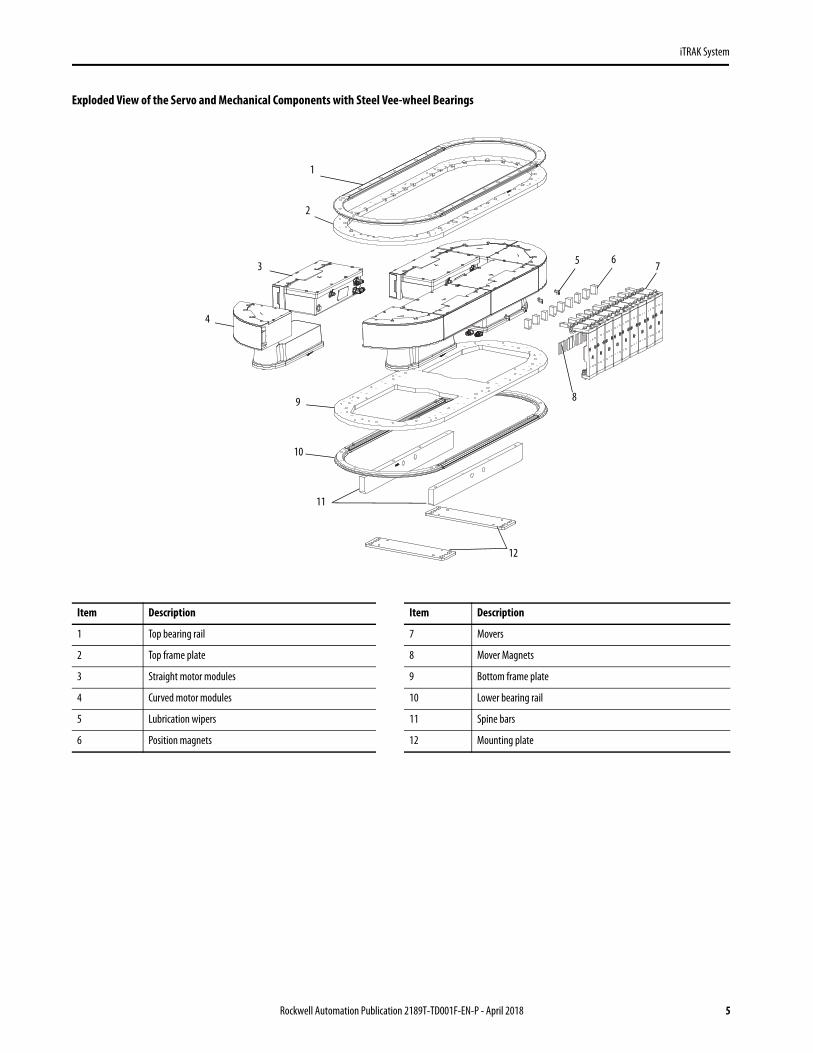
Exploded View of the Servo and Mechanical Components with Steel Vee-wheel Bearings
Item Description Item Description
1 Top bearing rail 7 Movers
2 Top frame plate 8 Mover Magnets
3 Straight motor modules 9 Bottom frame plate
4 Curved motor modules 10 Lower bearing rail
5 Lubrication wipers 11 Spine bars
6 Position magnets 12 Mounting plate
1
2
3
4
5 6 7
89
10
11
12
Rockwell Automation Publication 2189T-TD001F-EN-P - April 2018 5

iTRAK System
Electromechanical Components of an iTRAK System
iTRAK System Component Description
Motor module The motor module is an integrated drive and motor coil unit; it is referred to as a section in the firmware. Motor modules are available in straight and curved shapes.
Track frame The track frame is designed for your specific application. The track frame in combination with straight motor modules, curved motor modules, and bearing rails creates the track.
Bearing rails The bearing rails attach to the track frame. They provide precision guidance for the movers.
Mover The movers are passive magnetic components. They move along the track in response to the magnetic fields generated by the motor modules. You attach your application end effector to the mover.
Mover magnets Mover magnet plates can be used to build your own movers to optimize weight or bearing solutions. Depending on the mover catalog number, these magnet plates can be included with the mover or sold separately.
Position magnets Position magnets are used to actuate sensors in the track. These magnets are typically sold separately from the mover, but are pre-installed on fully assembled systems.
Power and Control Components of an iTRAK System
iTRAK System Component Description
Power circuitry and components The iTRAK power supply connects to the Kinetix 5700 power supply and generates the voltages that are required for the iTRAK system from the full bus voltage. It is used with other Kinetix 5700 components and branch circuit protection.
Bus conditioner module The bus conditioner module is mounted near the iTRAK for each power cable. It incorporates additional filtering and capacitance to improve dynamic servo response and increase reliability of the system.
Power cables The power bus cables are daisy chained between the motor modules. The number of motor modules on one daisy chain is system-dependent.
Gateway The gateway provides communication interface between the Logix controller and all motor modules. It also provides more motion processing for the motor modules.
USB I/O Executes discrete communication between the gateway and power components.
Communication cables Each motor module in the system has a communication cable that is connected directly to the gateway. Use only the cables that are provided with your system and referenced in this user manual.
Logix controller platform CompactLogix™ controller or ControlLogix® controller with Ethernet connection that supports Integrated Motion on EtherNet/IP.
Studio 5000® environment Studio 5000 Logix Designer application, version 21 or later, provides support to program, commission, and maintain the CompactLogix and ControlLogix controller families that you use with iTRAK system.
6 Rockwell Automation Publication 2189T-TD001F-EN-P - April 2018

iTRAK System
Typical iTRAK System
The following graphic shows a typical iTRAK system with TriMax™ bearings. Your system can vary in the quantity and layout of each component, but follows the same concept.
(1) See Kinetix 5700 Servo Drives User Manual. publication 2198-UM002, for more information on these components.
Item Description Item Description Item Description
Items that are not supplied with system. 12 iTRAK power supply I/O connections 19 Bearing rails
1 24V control power 18 iTRAK ready connection 21 Mover
2 Kinetix 5700 power supply 14 Studio 5000 Programming Interface 22 Straight motor module
4 Controller Items included in quote. 23 Curved motor module
5 Managed Ethernet Switch 3 Kinetix 5700 iTRAK power supply 24 iTRAK bus conditioner (not visible mounted between spine bars)
6 Machine Ethernet 11 USB cable Item included in system sale.
7 Contactor enable signal line 13 Motor module power bus and control power (number of cables vary by system) 20 Track frame
8 Mains power (460V nominal) 15 Gateway Recommended additional items.
9 Kinetix 5700 line voltage 16 Communication cable to motor module (one cable per motor module) 25 Lubrication pump (x3)
10 Plant Ethernet 17 Digital USB I/O module 26 Lubrication tube
21
22
23
7
4
16
13
18
9
17
19
14
6
20
1012
32
8
1
11
5
6
6
1
1
15
Branch Protection, Disconnect,Line Filter, and Functional Safety (1)
24V Control Power Supply
24
2526
19
Rockwell Automation Publication 2189T-TD001F-EN-P - April 2018 7

iTRAK System
Catalog Number Explanation - iTRAK System
The iTRAK system can be purchased fully assembled or as individual components that you assemble. This catalog number explanation describes assembled systems. The catalog numbers consist of characters, each of which identifies a specific option for that component. Use the catalog number explanation to understand the configuration of your iTRAK system.
System-level Catalog Number Explanation with Additional Special Order Options
2198T - E xx x xxx xxx x xx - xxx x - Qxxxx
iTRAK System Catalog Number Example
Catalog Number Description
2198T-E05H024000A05-020C-Qxxxx iTRAK system, horizontal, 2.4 m (7.87 ft) oval, (20) 50 x 50 movers
Customized (quote number reference)Power and Control ConfigurationB = 10 kW power and control modules
C = Kinetix 5700 iTRAK Power Supply
D = PCM components without a cabinet
Mover Quantity### = Number of movers
Mover Magnet Stack Length05 = 5 cm 10 = 10 cm 15 = 15 cm
Mechanical Solution StyleA = Vee-wheel bearings
C = TriMax bearings
Short Dimension (width)### = Total length of straight motor modules in the short dimension in decimeters 000 = Oval00A = Linear
Long Dimension (length)### = Total length of straight motor modules in the long dimension in decimeters
OrientationH = Horizontal (both dimensions horizontal) V = Vertical (short dimension vertical only)S = Stand up (long dimension vertical only)
Motor Coil Width05 = 5 cm 10 = 10 cm 15 = 15 cm
Module TypeE = Configured system
Bulletin Number2198T = iTRAK system
8 Rockwell Automation Publication 2189T-TD001F-EN-P - April 2018

iTRAK System
System Level Bill of Materials for a iTRAK System with TriMax Bearings
Example of a High-level BOM for Catalog Number 2198T-E05H024000C05-020C-Qxxxx
Cat. No. Description Qty
2198T-L16-T0504-A00N-2E1E-NSiTRAK linear module, 50 mm (1.99 in.) wide, 400 mm (15.7 in.) long, integral multi-phase iTRAK servo drive, integral multiple targets, absolute position sensor, IP65 with stainless steel cover, M23 connector
12
2198T-L16-T0504-B09L-2E1E-NSiTRAK curve module, intelligent, 50 mm (1.99 in.) wide, 90-deg arc, 254 mm (10 in.) radius, integral multi-phase iTRAK servo drive, integral multiple targets, absolute position sensor, IP65 with stainless steel cover, M23 connector, left
2
2198T-L16-T0504-B09R-2E1E-NSiTRAK curve module, intelligent, 50 mm (1.99 in.) wide, 90-deg arc, 254 mm (10 in.) radius, integral multi-phase iTRAK servo drive, integral multiple targets, absolute position sensor, IP65 with stainless steel cover, M23 connector, right
2
2198T-VT0505-C iTRAK mover, 50 mm (1.99 in.) wide, 50 mm (1.99 in.) long (excludes position magnet and lubricator) 20
2198T-NN-318 iTRAK position magnet, 31.8 mm (1.25 in.), north 10
2198T-NS-318 iTRAK position magnet, 31.8 mm (1.25 in.), south 10
2198T-AL-SYS iTRAK lubrication system with three digitally activated pumps with mounting brackets, three lubricant cartridges, and 20 m (66 ft) of tubing
1
2198T-W25K-ER Kinetix 5700 iTRAK power supply 1
2198T-WBCMOD iTRAK bus conditioner 2
2198T-G12-016-E Gateway enclosure assembly (with 2198T-G02-016-E gateway) 1
2198T-CHBFLS8-12AA06 Cable, intelligent power 6.0 m (19.7 ft), M23, Flying Lead 1
2198T-CHBFLS8-12AA09 Cable, intelligent power 9.0 m (29.5 ft), M23, Flying Lead 1
2198T-CHBP8S8-12P3 Cable, intelligent power, jumper 0.380 m (1.25 ft), M23 8
2198T-CHBP8S8-12P6 Cable, intelligent power, jumper 0.600 m (1.97 ft), M23 6
2198T-CC-08 Ethernet cord-set, M12 A-code, RJ45 plug, 8-pin, 8 m (26.2 ft) 16
626834-2400 Kit, Plate, iTRAK, standard, base, spine bars, top plates, and customer mounting plates 1
Rockwell Automation Publication 2189T-TD001F-EN-P - April 2018 9

iTRAK System
System Level Bill of Materials for a iTRAK System with Vee-wheel Bearings
Example of a High-level BOM for Catalog Number 2198T-E05H024000B05-020C
Cat. No. Description Qty
2198T-L16-T0504-A00N-2E1E-NSiTRAK linear module, 50 mm (1.99 in.) wide, 400 mm (15.7 in.) long, integral multi-phase iTRAK servo drive, integral multiple targets, absolute position sensor, IP65 with stainless steel cover, M23 connector
12
2198T-L16-T0504-B09L-2E1E-NSiTRAK curve module, intelligent, 50 mm (1.99 in.) wide, 90-deg arc, 254 mm (10 in.) radius, integral multi-phase iTRAK servo drive, integral multiple targets, absolute position sensor, IP65 with stainless steel cover, M23 connector, left
2
2198T-L16-T0504-B09R-2E1E-NSiTRAK curve module, intelligent, 50 mm (1.99 in.) wide, 90-deg arc, 254 mm (10 in.) radius, integral multi-phase iTRAK servo drive, integral multiple targets, absolute position sensor, IP65 with stainless steel cover, M23 connector, right
2
2198T-VT0505-A iTRAK mover, 50 mm (1.99 in.) wide, 50 mm (1.99 in.) long (excludes position magnet and lubricator) 20
2198T-NN-318 iTRAK position magnet, 31.8 mm (1.25 in.), north 10
2198T-NS-318 iTRAK position magnet, 31.8 mm (1.25 in.), south 10
2198T-AL-PAD-V iTRAK lubrication wipers 5
2198T-AL-SYS iTRAK lubrication system with three digitally activated pumps with mounting brackets, three lubricant cartridges, and 20 m (66 ft) of tubing
1
2198T-W25K-ER Kinetix 5700 iTRAK power supply 1
2198T-WBCMOD iTRAK bus conditioner 2
2198T-G12-016-E Gateway enclosure assembly (with 2198T-G02-016-E gateway) 1
2198T-CHBFLS8-12AA06 Cable, intelligent power 6.0 m (19.7 ft), M23, Flying Lead 1
2198T-CHBFLS8-12AA09 Cable, intelligent power 9.0 m (29.5 ft), M23, Flying Lead 1
2198T-CHBP8S8-12P3 Cable, intelligent power, jumper 0.380 m (1.25 ft), M23 8
2198T-CHBP8S8-12P6 Cable, intelligent power, jumper 0.600 m (1.97 ft), M23 6
2198T-CC-08 Ethernet cord-set, M12 A-code, RJ45 plug, 8-pin, 8 m (26.2 ft) 16
920435-2400 Kit, Plate, iTRAK, standard, base, spine bars, top plates, straight and curve rail, and customer mounting plates 1
10 Rockwell Automation Publication 2189T-TD001F-EN-P - April 2018

iTRAK System
Design Considerations
Use the following guidelines to help design the iTRAK system that includes an iTRAK power supply.
Basic System Design Requirements and Limitations
Controller Compatibility
Use a CompactLogix controller or ControlLogix controller with Ethernet connection that supports Integrated Motion on EtherNet/IP with your iTRAK system. Studio 5000 Logix Designer application, version 21 or later, provides support to program, commission, and maintain the CompactLogix and ControlLogix controller families that you use with iTRAK system.
Determine the Number iTRAK Power Supplies Required
The number of iTRAK power supplies can be scaled to match the power needs of the iTRAK system closely. Additional iTRAK power supplies can be added to the system as needed. The following factors impact the number of iTRAK power supplies required for a system.
• Output bus current• 24V control current• Cable length
Attribute Requirement
Studio 5000 Automation Engineering & Design Environment® Version 21.00 or later
Number of movers per controller, max 96
Motor modules per gateway, max 64
Temperature on the surface of the motor face, max 80 °C (176 °F)
Number of modules using one power cable, max Maximum number of cascaded motor modules is 16 (1)
(1) The maximum number of modules per cable can be less depending on power consumption. Contact Application Engineering for limitations.
Compatible Controllers
Platform Controller
ControlLogix system 5580 (1)
(1) The minimum firmware revision to use these processors is 1.103.
5570 (2)
(2) The communication to the gateway must be through 1756-ENxT modules capable of integrated motion on the EtherNet/IP network.
CompactLogix controllers 5380 (1) (3)
(3) The memory requirements and CPU utilization of typical iTRAK applications can reduce the possible catalog numbers available in these families. Work with Rockwell Automation® application engineering to determine suitability.
5370 (3)
5480 (1)
Rockwell Automation Publication 2189T-TD001F-EN-P - April 2018 11

iTRAK System
If needed, see Using Multiple iTRAK Power Supplies for information on how to connect a system with multiple iTRAK power supplies.
Output Bus Current
Sizing is the process of determining the required size and quantity of power hardware components and motors modules for an application. Sizing an iTRAK system involves many variables. Call a Rockwell Automation application engineer to size your system.
24V Control Power
The following criteria must be met for the operation of the system.• Sufficient current can be delivered.• The required voltage is maintained at the input to the iTRAK power supply.• Maximum iTRAK power supply input current is never exceeded.• Maintain an acceptable voltage drop from the iTRAK power supply to the iTRAK motor modules, see the
Maximum iTRAK Power Supply to Motor Module Cable Length.
The iTRAK power supply uses 24V control power to run all low voltage circuits and it distributes 24V control power to the iTRAK motor modules that are connected to it.
24V Current Requirements
Determine the amount of current required; add the current draw of the iTRAK power supply to the current used by each of the motor modules that are connected to that iTRAK power supply. Make sure that you include all iTRAK motor modules that are connected to both the A and B outputs. When designing the system, be sure to account for the 16 A pass through limit of the iTRAK power supply to the iTRAK motor modules. See Control Power Current Specifications on page 66 for the amount of current required for the iTRAK power supply and 2198T Straight and Curved Motor Modules on page 20 the iTRAK motor modules.
Input Voltage
See 24V DC Control Power Input (CP) Specifications for the control-power input-voltage requirements. The table shows the voltage that is required at the input connector on the iTRAK power supply. You must take in account for all voltage drops in wiring from the 24V power supply to the iTRAK power supply and the motor modules. 24V DC Control Power Input (CP) Specifications
Connector Input Voltage,Max
Input Voltage, Min iTRAK Power Supply Consumption, Max
Pass through to Motor Modules, Max
Total at Input,Max
24V DC Control Power Input (CP) 26.4V DC 21.6V DC 1 A 16 A 17 A
24V DC Control Power Output (ICP) Specifications
Connector Pass through to Motor Modules, Max (1)
(1) These ratings apply to both the total combined current from connector A and B, and also applies to the rated output for connector A or B individually.
24V DC Control Power Output to iTRAK (ICP) 16 A
12 Rockwell Automation Publication 2189T-TD001F-EN-P - April 2018

iTRAK System
iTRAK Power Supply Output Power Connections
The iTRAK power supply has two sets of output power cable connectors, referenced as A and B; they let you connect two power cables to the iTRAK system. The two sets of connectors have identical sets of signals, they are connected internally, and are interchangeable.
By using multiple cables the iTRAK power supply can deliver control power to more iTRAK motor modules, see Maximum iTRAK Power Supply to Motor Module Cable Length.
Maximum iTRAK Power Supply to Motor Module Cable Length
Account for the resistive losses in the 2198T-CHBFLS8-12AAxx power cable that connects the iTRAK power supply to motor modules. Make sure that there is sufficient control power voltage at the input to all motor modules. The amount of current flow and the number of motor modules that are connected in series limits the length of this cable.
See Number of Series A Motor Modules Connected to a Single Input Cable or Number of Series B Motor Modules Connected to a Single Input Cable to determine the maximum length of a power cable that is based on the number of motor modules that are connected to it at the minimum control-power input voltage. This table is for 2198T-CHBFLS8-12AAxx cables, which are the only cables supported.
Cables between the iTRAK power supply and the iTRAK system are limited to 30 m (98 ft).
The cable length calculations are made separately for output A and B.Number of Series A Motor Modules Connected to a Single Input Cable
Cable Length (1)
(1) The cable lengths that are shown are for the cable from the iTRAK power supply to the first motor module. It is assumed that the subsequent motor modules are connected using short motor module-to-motor module cables.
Motor Module Quantity
1 2 3 4 5 6 7 8 9 10 11
3 m (9.8 ft)
6 m (19.7 ft)
9 m (29.5 ft)
12 m (39.4 ft)
15 m (49.2 ft)
30 m (98.4 ft)
Number of Series B Motor Modules Connected to a Single Input Cable
Cable Length (1)
(1) The cable lengths that are shown are for the cable from the iTRAK power supply to the first motor module. It is assumed that the subsequent motor modules are connected using short motor module-to-motor module cables.
Motor Module Quantity
1 2 3 4 5 6 7 8 9 10 11 12 13 14 15 16 17 18
3 m (9.8 ft)
6 m (19.7 ft)
9 m (29.5 ft)
12 m (39.4 ft)
15 m (49.2 ft)
30 m (98.4 ft)
Rockwell Automation Publication 2189T-TD001F-EN-P - April 2018 13

iTRAK System
Choose a 2198-Pxxx Kinetix 5700 Power Supply
The iTRAK power supply connects to the Kinetix 5700 DC-bus created by the 2198-Pxxx, Kinetix 5700 power supply. The Kinetix 5700 power supply must be sufficiently sized to support the iTRAK power supply load and any other servo drive load.
Sizing an iTRAK system involves many variables. Call a Rockwell Automation application engineer to size your system.
The iTRAK power supply creates two power buses that are used by iTRAK motor modules. The topology of the iTRAK motor modules uses the center voltage bus as a return, and the upper and lower as sources.
Once the output current requirements of the iTRAK power supplies are known, the amount of power that is required from the Kinetix 5700 power supply for the iTRAK power supplies is calculated by using this equation.
P (Watts) = Output Current * (Nominal Bus Voltage 1 + Nominal Bus Voltage 2) + iTRAK Power Supply Losses
See Power Dissipation Specifications on page 67, for iTRAK power supply losses.
Any other Kinetix 5700 components that are connected to the Kinetix 5700 power supply bus must also be added to this number, see Kinetix Servo Drives Specifications Technical Data, publication KNX-TD003.
Bus Output (IDC) Specifications shows the nominal bus voltages and currents of the iTRAK power supply.
The Kinetix 5700 power supply that is used must be able to deliver the total power to be consumed. The Kinetix 5700 Servo Drives User Manual, publication 2198-UM002, has more information.
Kinetix Servo Drives Specifications Technical Data, publication KNX-TD003, contains the power ratings of the 2198-Pxxx Kinetix 5700 power supplies. Their power ratings are derived assuming 460V AC line input; based on your line voltage scale their power rating.
Verify that the shunting capacity of the system that the 2198-Pxxx Power Supply manages is not exceeded. For further details, see Shunting Capacity.
Shunting Capacity
The iTRAK power supply can move regenerative energy from the iTRAK system back to the Kinetix 5700 DC bus. The Kinetix 5700 power supply turns on a shunt to limit DC bus voltage if the DC bus voltage gets too high. The amount of shunting capacity available depends on which 2198-Pxxx Kinetix 5700 power supply that is used and whether an external shunt is present. See the Kinetix 5700 Servo Drives User Manual, publication 2198-UM002, for more information on shunting capacity.
Bus Output (IDC) Specifications
Connector Continuous Output Current Peak Output Current Nominal H to DC-Voltage Nominal L to DC- Bus Voltage
Bus Output (IDC) (1)
(1) These ratings apply to both the total combined current from connector A and B, and also applies to the rated output for connector A or B individually.
12.5 A 25.0 A 330V DC 165V DC
14 Rockwell Automation Publication 2189T-TD001F-EN-P - April 2018

iTRAK System
Kinetix 5700 System Design
When the number of iTRAK power supplies and type of 2198-Pxxx Kinetix 5700 power supplies are known, the Kinetix 5700 system design can be determined.
The important items to be determined and designed are listed here.• Connections of the Kinetix 5700 components including the iTRAK power supply• Cabinet selection• Cabinet layout and wiring• Other components as required such as contactor and line filter
See the Kinetix 5700 Servo Drives User Manual, publication 2198-UM002, for information regarding design of these Kinetix 5700 components.
Wire the iTRAK System
An iTRAK power supply can power up to 20 Series A or 32 Series B motor modules depending on current requirements. See Wiring an iTRAK System with an iTRAK Power Supply for a typical layout and how to wire a system that uses one iTRAK power supply. Detailed wiring the connections to the iTRAK power supply are shown in Kinetix 5700 iTRAK Power Supply Installation Instructions, publication 2198T-IN001.
Wiring an iTRAK System with an iTRAK Power Supply
Wiring the connections from multiple iTRAK power supplies is shown in Connecting Multiple iTRAK Power Supplies in a System on page 16 and Wiring Multiple iTRAK Power Supplies to the Digital USB I/O Module on page 17.
See the Kinetix 5700 Servo Drives User Manual, publication 2198-UM002, for details on how to wire the rest of the Kinetix 5700 system. Information on how to wire to the iTRAK power supply is found in Kinetix 5700 iTRAK Power Supply Installation Instructions, publication 2198T-IN001.
Item Description
1 2198T-CHBFLS8-12AAxx, iTRAK power supply to motor module cable
2 2198T-CHBP8S8-12P3, power cable
3 2198T-CHBP8S8-12P6, power cable
4 2198T-WBCMOD, iTRAK bus conditioner
2198-Pxxx Kinetix 5700
Power Supply
2198T-W25K-ER Kinetix 5700 iTRAK Power
SupplyOutput
AOutput
B
1
1
2 4
2 24
3
3
3
2 2 2 2 2 2
32222
Rockwell Automation Publication 2189T-TD001F-EN-P - April 2018 15

iTRAK System
Using Multiple iTRAK Power Supplies
Follow these guidelines when using multiple iTRAK power supplies in an iTRAK system.
When using multiple iTRAK power supplies, the system must be parsed into separate electrical pieces for each of the iTRAK power supplies.
The iTRAK power supply is not designed to have the output buses of multiple power supplies connected together to create one bus of higher current capacity.
Use the following scenario to understand the use of multiple iTRAK power supplies for systems that require a higher current draw. In this example, part of the track has a high-power demand, and the rest of the track has a lower power demand. In this case iTRAK power supply 1 powers the first group of ten motor modules, while iTRAK power supply 2 provides power to the remaining six motor modules. The DC buses of these two groups are electrically isolated from each other as shown in Connecting Multiple iTRAK Power Supplies in a System.
Connecting Multiple iTRAK Power Supplies in a System
One gateway can interface to multiple iTRAK power supplies through the Digital USB I/O Module. When you use this configuration, connect the Enable and Clear Fault signals in parallel, and connect the IPS Ready signal in series through all iTRAK power supplies as shown in Wiring Multiple iTRAK Power Supplies to the Digital USB I/O Module.
IMPORTANT In systems that use multiple iTRAK power supplies, make sure that the output bus of one power supply is never connected to the output bus of another power supply.
Item Description
1 2198T-CHBFLS8-12AAxx, iTRAK power supply to motor module cable
2 2198T-CHBP8S8-12P3, power cable
3 2198T-CHBP8S8-12P6, power cable
4 2198T-WBCMOD iTRAK bus conditioner
ATTENTION: Power from iTRAK power supply 1 must not be connected to the power from iTRAK power supply 2.
2198-Pxxx Kinetix 5700
Power Supply
2198T-W25K-ER Kinetix 5700 iTRAK Power
Supply 1Output
A
2198T-W25K-ER Kinetix 5700 iTRAK Power
Supply 2Output
BOutput
AOutput
B
1
3
3
2 2
4
4
42
1
3
3 2 2
2 2 2
3
1
16 Rockwell Automation Publication 2189T-TD001F-EN-P - April 2018

iTRAK System
Wiring Multiple iTRAK Power Supplies to the Digital USB I/O Module
iTRAK System Track
The track is composed of the upper and lower frame, spine rails, motor modules, bearings, and movers. The weights that are shown here are the average weight of the track per meter (foot).
WeightsFrame Width Weight, Approx
50 mm 123 kg/m (83 lb/ft)
100 mm 156 kg/m (105 lb/ft)
150 mm 189 kg/m (127 lb/ft)
1
2
3
4
5
ENABLE
CLEAR FAULT24V COM
(1)
24V COM (1)
SHIELD
24V
24V
iPS READY
24V
24V COM
IN1
COM
IN2
COM
SHLD
OUT 00 NO
OUT 00 C
OUT 01 NO
OUT 01 C
IN00 A
IN00 B
1
2
3
4
ENABLE
CLEAR FAULT24V COM
(1)
24V COM (1)
SHIELD
IPS READY
IPS READY IN
-
+
-
+
IN1
COM
IN2
COM
SHLD
2198T-GUSBDigital USB I/O
Module
2198T-W25K-ERKinetix 5700 iTRAK
Power Supply 2
Digital Input(IOD) Connector
ITRAK Power SupplyReady (IR) Connector
ITRAK Power SupplyReady (IR) Connector
2198T-W25K-ERKinetix 5700 iTRAK
Power Supply 1
Digital Input(IOD) Connector
2198T-Gxx-xxx-EGateway
USB Port
USB Port
(1) Only one connection to 24V Com is required for each iTRAK power supply. Either pin 2 or pin 4 must be connected, it is not necessary to connect both.
Rockwell Automation Publication 2189T-TD001F-EN-P - April 2018 17

iTRAK System
Motor Module
The motor module is an integrated drive and motor coil unit; it is referred to as a section in the firmware and software. Motor modules are available in straight and curved shapes. The motor module includes three status indicators: control power, motor power, and communication.
Bulletin 2198T iTRAK motor modules are compatible and can be mixed mechanically, regardless of the series.• If you have any series B modules in your system, the minimum firmware revision is 1.107 for the entire system.• There are minor differences in labeling and appearance but the modules are functionally the same
.
Catalog Number Explanation
2198T - L 16- T xx 04 - x xx x - 2E 1E - NS
2198T Straight and Curved Motor Modules
Cat. No. Motor Module TypeMotor Lengthmm (in.)
Motor Coil Width mm (in.)
2198T-L16-T0504-AOON-2E1E-NS Straight
400 (15.7)
50 (2.0)2198T-L16-T0504-B09L-2E1E-NS Curved left
2198T-L16-T0504-B09R-2E1E-NS Curved right
2198T- L16-T1004-AOON-2E1E-NS Straight
100 (4.0)2198T-L16-T1004-B09L-2E1E-NS Curved left
2198T- L16-T1004-B09R-2E1E-NS Curved right
2198T-L16-T1504-AOON-2E1E-NS Straight
150 (5.9)2198T-L16-T1504-B09L-2E1E-NS Curved left
2198T-L16-T1504-B09R-2E1E-NS Curved right
Motor Modules (catalog numbers 2198T-L16-T0504-AOON-2E1E-NS and 2198T-L16-T0504-B09L-2E1E-NS are shown)
Functional SafetyNS = No safety includedCommunication Connections1E = External tap only - starPower Connections2E = External taps only - daisy-chainDrive OrientationN = Not requiredL = LeftR = RightArc Angle00 = Linear09 = 90º arcRadius TypeA = LinearB = Constant radiusMotor Length04 = 40 cm Motor Coil Width05 = 5 cm 10 = 10 cm 15 = 15 cm Motor OrientationT = TransverseNominal Voltage16 = 160V bus Module TypeL = Integrated drive/motor sectionBulletin Number2198T = iTRAK system
18 Rockwell Automation Publication 2189T-TD001F-EN-P - April 2018
iTRAK System
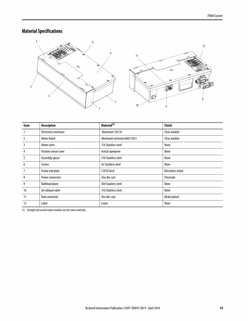
Material Specifications
Item Description Material(1)
(1) Straight and curved motor modules use the same materials.
Finish
1 Electronics enclosure Aluminum 356-T6 Clear anodize
2 Motor frame Aluminum extrusion 6063-T651 Clear anodize
3 Motor cover 316 Stainless steel None
4 Position sensor cover Acetal copolymer None
5 Assembly spacer 316 Stainless steel None
6 Screws A2 Stainless steel None
7 Frame end plate C1018 Steel Electroless nickel
8 Power connectors Zinc die-cast Chromate
9 Bulkhead plate 304 Stainless steel None
10 Air exhaust valve 316 Stainless steel None
11 Data connector Zinc die-cast Nickel plated
12 Label Lexan None
2
5 6
4
1
710 9
8
12
11
3
Rockwell Automation Publication 2189T-TD001F-EN-P - April 2018 19
iTRAK System
Technical Specifications2198T Straight and Curved Motor Modules
Attribute 2198T-L16-Txxxx-xxxx-2E1E-NS
DC motor module bus
Input voltages 330V DC and 165V DC
Input current 8 A rms, max
Control power DC input voltage 24V DC
Control power DC input current 0.45 A, max
Motor stator insulation class Class B, 130 °C (266 °F)
Cascaded input/output DC motor module power bus
Input voltages 330V DC and 165V DC
Input current 25 A rms
Control power DC input voltage 18.6… 28V DC
Control power DC input current 8 A
Number of cascaded power cables
Series A motor modules Eight motor modules, max
Series B motor modules 16 motor modules, max
Communication RS-422, 7.32 MHz
Temperature, operating 0…40 °C (32…104 °F)
Module ingress protection IP65
UL listed Category XDNZ: Electronically Protected Motors with Integral Controllers for Industrial Use
20 Rockwell Automation Publication 2189T-TD001F-EN-P - April 2018

iTRAK System
Precision
All specifications assume the following.• The mover is catalog number 2198T-VTxxxx-x and has no additional mass attached.• Temperature has reached steady state.
Static Accuracy
AttributeAbsolute Accuracy (1)
mm (in.)
(1) Specifications are for any mover on any section.
Straight motor module ± 0.5 (0.02)
Curve motor module ± 2.5 (0.98)
Static Unidirectional Repeatability
AttributeSingle Mover to Single Pointmm (in.)
Any Mover to Any Pointmm (in.)
Straight motor module < 0.03 (0.001) ± 0.1 (0.004)
Curve motor module ± 0.2 (0.008) ± 0.5 (0.02)
Dynamic Performance
AttributeSpeedm/s (ft/s)
Mover to Mover Position Variation mm (in.)
Curve to Straight Transition Distance (2)
mm (in.)
(2) Distance that is required to achieve specified following error performance when making the transition from a curve into a straight.
Straight module
0.05 (0.16)
±2.0 (0.08)
30.0 (1.18)
0.25 (0.82) 100.0 (9.93)
1.0 (3.3) 150.0 (5.91)
2.5 (8.2) 225.0 (8.86)
5.0 (16.0) 400.0 (15.75)
Curve module
0.05 (0.16)
±20.0 (0.8)
—
0.25 (0.82) —
1.0 (3.3) —
2.5 (8.2) —
5.0 (16.0) ±30.0 (1.18) —
At motor module to motor module transition (1)
(1) Describes dynamic operation across a transition. Static operation on a transition is not recommended.
0.05 (0.16)
±3.0 (0.12)
—
0.25 (0.82) —
1.0 (3.3) —
2.5 (8.2) —
5.0 (16.0) —
Rockwell Automation Publication 2189T-TD001F-EN-P - April 2018 21
iTRAK System
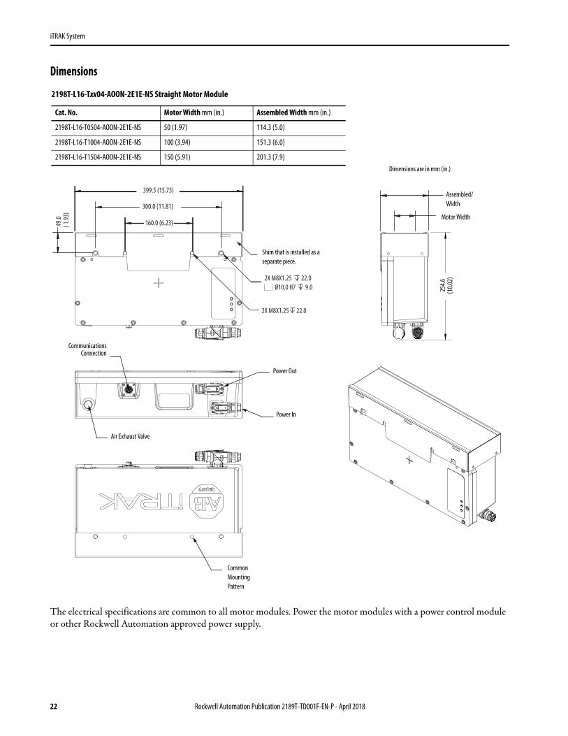
Dimensions
The electrical specifications are common to all motor modules. Power the motor modules with a power control module or other Rockwell Automation approved power supply.
399.5 (15.75)
300.0 (11.81)
160.0 (6.23) 49.0
( 1.93
)
2X M8X1.25 22.0
2X M8X1.25 22.0 Ø10.0 H7 9.0 25
4.6 (1
0.02)
CommunicationsConnection
Power Out
Power In
Common Mounting Pattern
Assembled/Width
Motor Width
2198T-L16-Txx04-AOON-2E1E-NS Straight Motor Module
Cat. No. Motor Width mm (in.) Assembled Width mm (in.)
2198T-L16-T0504-AOON-2E1E-NS 50 (1.97) 114.3 (5.0)
2198T-L16-T1004-AOON-2E1E-NS 100 (3.94) 151.3 (6.0)
2198T-L16-T1504-AOON-2E1E-NS 150 (5.91) 201.3 (7.9)Dimensions are in mm (in.)
Shim that is installed as a separate piece.
Air Exhaust Valve
22 Rockwell Automation Publication 2189T-TD001F-EN-P - April 2018

iTRAK System
The electrical specifications are common to all motor modules. Power the motor modules with a power control module or other Rockwell Automation approved power supply.
WeightsCat. No. Motor Modules Type Frame Width Weight, Approx kg (lb)
2198T-L16-T0504-AOON-2E1E-NS
Straight
50 mm 15.2 (33.5)
2198T-L16-T1004-AOON-2E1E-NS 100 mm 20.0 (44.1)
2198T-L16-T1504-AOON-2E1E-NS 150 mm 26.2 (57.8)
2198T-L16-T0504-B09x-2E1E-NS
Curved
50 mm 17.0 (37.5)
2198T-L16-T1004-B09x-2E1E-NS 100 mm 20.3 (44.8)
2198T-L16-T1504-B09x-2E1E-NS 150 mm 29.0 (63.9)
167.9
(6.61
)
536.8(21.13)
R255.3 R205.0
90°
10°
20°
30°
2X M8 X 1.25 22.0Ø10.0 H7 9.0
2X M8 X 1.25 22.0
20°
CommunicationConnection
Power Out
Power In
CommonMounting
Pattern
AssembledWidthMotor
Width
2198T-L16-Txx04-B09x-2E1E-NS Curved Motor Module
Cat. No. Motor Width mm (in.) Assembled Width mm (in.)
2198T-L16-T0504-B09x-2E1E-NS 50 (1.97) 114.3 (5.0)
2198T-L16-T1004-B09x-2E1E-NS 100 (3.94) 151.3 (6.0)
2198T-L16-T1504-B09x-2E1E-NS 150 (5.91) 201.3 (7.9) Dimensions are in mm (in.)
Air Exhaust Valve
Rockwell Automation Publication 2189T-TD001F-EN-P - April 2018 23

iTRAK System
Identify Motor Module SeriesTo differentiate between series A and series B motor modules, examine the status indicators or nameplate.
Series A Motor Module Status Indicators
Series B Motor Module Status Indicators (1)
(1) If your motor module has a series B labels it is a series B motor module, however, some series B motor modules shipped with series A labels. If you have a motor module with series A labels, check the nameplate to confirm the series.
Straight Motor Module Curved Motor Module
Straight Motor Module Curved Motor ModuleCurved Motor Module
Left
Right
CAUTION
WARNING
CONTROL POWER
COMMUNICATION
DRIVE ENABLED
DANGERHazardous Voltage InsidePower Off. Lockout/Tagout andwait 5 minutes
PINCH POINTS NEARBYSudden motion. Stand ClearPower Off. Lockout/Tagout
Metal Surfaces May be HotDo not touchPower Off. Allow to cool down
Magnetic FieldCan be harmful topacemaker wearers
B624958
CAUTION
24 Rockwell Automation Publication 2189T-TD001F-EN-P - April 2018
iTRAK System
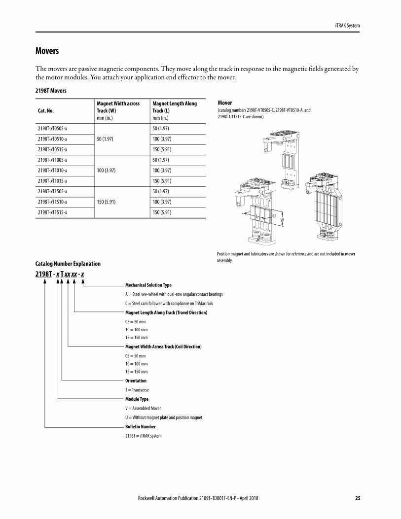
Movers
The movers are passive magnetic components. They move along the track in response to the magnetic fields generated by the motor modules. You attach your application end effector to the mover.
Catalog Number Explanation
2198T - x T xx xx - x
2198T Movers
Cat. No. Magnet Width across Track (W)mm (in.)
Magnet Length Along Track (L)mm (in.)
2198T-xT0505-x
50 (1.97)
50 (1.97)
2198T-xT0510-x 100 (3.97)
2198T-xT0515-x 150 (5.91)
2198T-xT1005-x
100 (3.97)
50 (1.97)
2198T-xT1010-x 100 (3.97)
2198T-xT1015-x 150 (5.91)
2198T-xT1505-x
150 (5.91)
50 (1.97)
2198T-xT1510-x 100 (3.97)
2198T-xT1515-x 150 (5.91)W
Position magnet and lubricators are shown for reference and are not included in mover assembly.
Mover (catalog numbers 2198T-VT0505-C, 2198T-VT0510-A, and 2198T-UT1515-C are shown)
Mechanical Solution Type
A = Steel vee-wheel with dual-row angular contact bearings
C = Steel cam follower with compliance on TriMax rails
Magnet Length Along Track (Travel Direction)
05 = 50 mm
10 = 100 mm
15 = 150 mm
Magnet Width Across Track (Coil Direction)
05 = 50 mm
10 = 100 mm
15 = 150 mm
Orientation
T = Transverse
Module Type
V = Assembled Mover
U = Without magnet plate and position magnet
Bulletin Number
2198T = iTRAK system
Rockwell Automation Publication 2189T-TD001F-EN-P - April 2018 25

iTRAK System
Material Specifications
The follow figures show the material that is used to assemble the mover.
2198T-VTxxxx-A Mover and Position Magnet
Item Part Material Finish
1 Upper inboard plate
Aluminum Anodized clear2 Upper outboard plate
3 Lower plate
4 Base plate
5 Bearing Alloy Steel —
6 Bearing cage Polyamide —
7 Sensor Magnet Bracket Aluminum Anodize Clear
8 Sensor Magnet Neodymium Nickel Plating
9 Magnet Plate Carbon Steel Nickel Plating
10 Drive Magnet Neodymium Nickel Plating
12 Bumper Neoprene —
13 Screws Class 12.9 alloy steel Black-oxide
14 Screws Class 12.9 alloy steelBlack-oxide
15 Bolts Class 12.9 alloy steel
16 Screws Class 12.9 alloy steel Black-oxide
5
2
1312
1
3
14
4
15
6
13
Lower Plate Bottom View
3
5 5
5 5
Outside ViewInside View
Inboard And Outboard Plates Top View
2
14
16
8
9
10
11
26 Rockwell Automation Publication 2189T-TD001F-EN-P - April 2018

iTRAK System
2198T-xTxxxx-C Mover and Magnets
Item Part Material Finish
1 Top Plate
Aluminum Anodize Clear2 Base Plate
3 Bottom Plate
4 Cam Follower Alloy Steel, Polyamide, Plastic, Rubber -
5 Cam Follower Compliance Alloy Steel -
6 Bumper Polyurethane -
7 Screw Class 12.9 Alloy Steel Black Oxide
8 Drive Magnet Neodymium Nickel Plating
9 Sensor Magnet Neodymium Nickel Plating
10 Magnet Plate Carbon Steel Nickel Plating
11 Sensor Magnet Bracket Aluminum Anodize Clear
12 Shoulder Screw Stainless Steel -
13 Hex Nut Stainless Steel -
1
7
12
2
4
4
5
5
9
8
10
11
7
13
7
3
6
7
Rockwell Automation Publication 2189T-TD001F-EN-P - April 2018 27

iTRAK System
Dimensions
2198T-VTxx05-A Mover
69.0(2.72)
72.2(2.84)
28.0(1.10)
14.0(0.55)
46.7(1.84)
63.5(2.50)
20.5(0.81) 12.5
2X Ø8.0 4.0M6 X 1.0-6H 12.5
M6 X 1.0-6H
160.2(6.31)
REF.
4 REF(0.15)
E
A
D
110.7(4.36)
7 REF(0.28)
2X Ø5 - H7
B
C
63.5(2.50)
40.0(1.57)
0.02M5X0.8 - H6 0.15
Cat. No. A mm (in.) B mm (in.) C mm (in.) D mm (in.) E mm (in.)
2198T-VT0505-A 232.3 (9.15) 61.56 (2.42) 120 (4.72) 50 (1.97) 32.27 (1.27)
2198T-VT1005-A 269.3 (10.60) 65.00 (2.59) 150 (5.91) 100 (3.94) 25.77 (1.015)
2198T-VT1505-A 319.3 (12.57) 75.00 (2.95) 180 (7.09) 150 (5.91) 25.77 (1.015)
Dimensions are in mm (in.)
Position magnet and lubricators are shown for reference and are not included in mover assembly.
All dimensions are for reference.
28 Rockwell Automation Publication 2189T-TD001F-EN-P - April 2018

iTRAK System
2198T-VTxx10-A Mover
100.0(3.94)
22.0(0.87)
28.5(1.12)
65.0(2.56)
32.5(1.28)
17.5(0.69)
2X Ø6.0 4H7M5 X 0.8-6H 14
M5 X 0.8-6H 14
3 REF(0.12)
4 REF(0.16)
110.7(4.36)
A
80.0(3.15)
C
B
4X M5 X0.8 - 6H 0.15
2X Ø5.000 - H7 +0.012 0.000
160.2(6.31)
REF.
D
E
0.02
103.2(4.06)
Dimensions are in mm (in.)Cat. No. A mm (in.) B mm (in.) C mm (in.) D mm (in.) E mm (in.)
2198T-VT0510-A 239.37 (9.35) 68.56 (2.70) 120 (4.72) 50 (1.97) 32.27 (1.27)
2198T-VT1010-A 276.37 (10.88) 72.06 (2.84) 150 (5.91) 100 (3.94) 25.77 (1.015)
2198T-VT1510-A 326.37 (12.85) 82.06 (3.23) 180 (7.09) 150 (5.91) 25.77 (1.015)
Position magnet and lubricators are shown for reference and are not included in mover assembly.
All dimensions are for reference.
Rockwell Automation Publication 2189T-TD001F-EN-P - April 2018 29

iTRAK System
2198T-VTxx15-A Mover
100.0(3.94)
165.2(6.50)
162.0(6.38)
65.0(2.56)
22.0(0.87)
2X Ø6.0 4H7M5 X 0.8-6H 14
M5 X 0.8-6H 14
28.5(1.12)
D A
110.7(4.36)E
4 REF(0.15)
3 REF(0.12)
B
C
4X M5 X 0.8 - 6H 0.15
2X Ø5.000 - H7 +0.012 0.02
0.00080.0
(3.15)160.2(6.31)
REF.
17.5(0.69)
31.0(1.22)
32.5(1.28)
Dimensions are in mm (in.)Cat. No. A mm (in.) B mm (in.) C mm (in.) D mm (in.) E mm (in.)
2198T-VT0515-A 239.37 (9.35) 68.56 (2.70) 120 (4.72) 50 (1.97) 32.27 (1.27)
2198T-VT1015-A 276.37 (10.88) 72.06 (2.84) 150 (5.91) 100 (3.94) 25.77 (1.015)
2198T-VT1515-A 326.37 (12.85) 82.06 (3.23) 180 (7.09) 150 (5.91) 25.77 (1.015)
Position magnet and lubricators are shown for reference and are not included in mover assembly.
All dimensions are for reference.
30 Rockwell Automation Publication 2189T-TD001F-EN-P - April 2018
iTRAK System
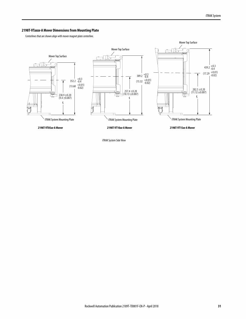
2198T-VTxxxx-A Mover Dimensions from Mounting Plate
439.2 +0.3-0.4
282.5 ±0.20(11.12 ±0.007)
(17.29 +0.01)-0.02)
Lc
352.2+0.3-0.4
(13.68
238.9 ±0.20(9.4 ±0.007)
Lc
+0.01)-0.02)
389.2
(15.32
+0.3-0.4
257.4 ±0.20(10.13 ±0.007)
Lc
+0.01)-0.02)
iTRAK System Mounting Plate
Mover Top Surface
iTRAK System Side View
iTRAK System Mounting Plate
Mover Top Surface
iTRAK System Mounting Plate
Mover Top Surface
Centerlines that are shown align with mover magnet plate centerline.
2198T-VT05xx-A Mover 2198T-VT10xx-A Mover 2198T-VT15xx-A Mover
Rockwell Automation Publication 2189T-TD001F-EN-P - April 2018 31

iTRAK System
2198T-VTxx05-C Mover
69.0(2.72)
27.6(1.09)
162.1(6.38)
40.1(1.58)
38.0(1.50)
30.8(1.21)
E
4X M5 X 0.8-6H Thru
2X Ø 5.000 (0.1968) H7 Thru
± 0.015(± 0.0006)
40.0(1.57)
3.1(0.12)
20.0(0.79)
4X M5 X 0.8-6H Thru 2X Ø 6.000 (0.2362) H7 4.0 (0.16)
108.3(4.26)
109.7(4.31)
0.55(0.022)
D C
A
B
F
Cat. No. A mm (in.) B mm (in.) C mm (in.) D mm (in.) E mm (in.) F mm (in.)
2198T-VT0505-C 49.00 (1.929) 130.00 (5.118) 226.7 (8.93) 165.1 (6.50) 50 (2.0) 32.5 (1.28)
2198T-VT1005-C47.50 (1.870)
170.00 (6.693) 263.7 (10.38) 202.1 (7.96) 100 (4.0)26.0 (1.02)
2198T-VT1505-C 220.00 (8.661) 313.7 (12.35) 252.1 (9.93) 150 (5.9)
Dimensions are in mm (in.)
Position magnet is shown for reference and is not included in mover assembly.
All dimensions are for reference.
Reference
Bumper
32 Rockwell Automation Publication 2189T-TD001F-EN-P - April 2018

iTRAK System
2198T-VTxx10-C Mover
100.0(3.94)
56.0(2.20)
27.6(1.09)
162.1(6.38)
40.1(1.58)
30.8(1.21)
108.3(4.26)
3.1(0.12)
40.0(1.57)
80.0(3.15)
± 0.015 (0.0006)
4X M5 X 0.8-6H Thru 2X Ø 6.000 (0.2362) H7 4.0 (0.16)
4X M5 X 0.8-6H Thru
2X Ø 5.000 (0.1968) H7 Thru
109.7(4.31)
0.55(0.022)
C BDE
F
A
Dimensions are in mm (in.)Cat. No. A mm (in.) B mm (in.) C mm (in.) D mm (in.) E mm (in.) F
2198T-VT0510-C 49.00 (1.929) 130.00 (5.118) 226.7 (8.93) 165.1 (6.50) 50 (2.0) 32.5 (1.28)
2198T-VT1010-C47.50 (1.870)
170.00 (6.693) 263.7 (10.38) 202.1 (7.96) 100 (4.0)26.0 (1.02)
2198T-VT1510-C 220.00 (8.661) 313.7 (12.35) 252.1 (9.93) 150 (5.9)
Position magnet is shown for reference and is not included in mover assembly.
All dimensions are for reference.
Bumper
Rockwell Automation Publication 2189T-TD001F-EN-P - April 2018 33

iTRAK System
2198T-VTxx15-C Mover
27.6(1.09)
162.1(6.38)
40.1(1.58)
162.0(6.38)
56.0(2.20)
100.0(3.94)
3.1(0.12)
± 0.015 (0.0006)
40.0(1.57)
80.0(3.15)
30.8(1.21)
108.3(4.26)
4X M5 X 0.8-6H Thru 2X Ø 6.000 (0.2362) H7 4.0 (0.16)
4X M5 X 0.8-6H Thru2X Ø 5.000 (0.1968) H7 Thru
109.7(4.31)
0.55(0.022)
A
BCDE
F
Dimensions are in mm (in.)Cat. No. A mm (in.) B mm (in.) C mm (in.) D mm (in.) E mm (in.) F mm (in.)
2198T-VT0515-C 49.00 (1.929) 130.00 (5.118) 226.7 (8.93) 165.1 (6.50) 50 (2.0) 32.5 (1.28)
2198T-VT1015-C47.50 (1.870)
170.00 (6.693) 263.7 (10.38) 202.1 (7.96) 100 (4.0)26.0 (1.02)
2198T-VT1515-C 220.00 (8.661) 313.7 (12.35) 252.1 (9.93) 150 (5.9)
Position magnet is shown for reference and is not included in mover assembly.
All dimensions are for reference.
Bumper
34 Rockwell Automation Publication 2189T-TD001F-EN-P - April 2018

iTRAK System
2198T-VTxxxx-C Mover Dimensions from Mounting Plate
439.2 +0.3-0.4
282.5 ±0.20(11.12 ±0.007)
(17.29 +0.01)-0.02)
Lc
352.2+0.3-0.4
(13.68
238.9 ±0.20(9.4 ±0.007)
Lc
+0.01)-0.02)
389.2
(15.32
+0.3-0.4
257.4 ±0.20(10.13 ±0.007)
Lc
+0.01)-0.02)
iTRAK System Mounting Plate
Mover Top Surface
iTRAK System Side View
iTRAK System Mounting Plate
Mover Top Surface
iTRAK System Mounting Plate
Mover Top Surface
Centerlines that are shown align with mover magnet plate centerline.
2198T-VT05xx-C Mover 2198T-VT10xx-C Mover 2198T-VT15xx-C Mover
Rockwell Automation Publication 2189T-TD001F-EN-P - April 2018 35
iTRAK System
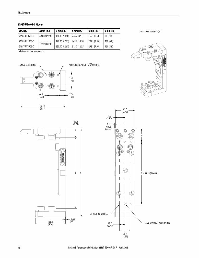
2198T-UTxx05-C Mover
27.6(1.09)
162.1(6.38)
40.1(1.58)
38.0(1.50)
D C
30.8(1.21)
4X M5 X 0.8-6H Thru
2X Ø 5.000 (0.1968) H7 Thru
A
B ± 0.015 (0.0006)
40.0(1.57)
69.0(2.72)
3.1(0.12)
34.5(1.36)
20.0(0.79)
4X M5 X 0.8-6H Thru 2X Ø 6.000 (0.2362) H7 4.0 (0.16)
108.3(4.26)
0.55(0.022)
Cat. No. A mm (in.) B mm (in.) C mm (in.) D mm (in.) E mm (in.)
2198T-UT0505-C 49.00 (1.929) 130.00 (5.118) 226.7 (8.93) 165.1 (6.50) 50 (2.0)
2198T-UT1005-C47.50 (1.870)
170.00 (6.693) 263.7 (10.38) 202.1 (7.96) 100 (4.0)
2198T-UT1505-C 220.00 (8.661) 313.7 (12.35) 252.1 (9.93) 150 (5.9)
Dimensions are in mm (in.)
All dimensions are for reference.
Bumper
36 Rockwell Automation Publication 2189T-TD001F-EN-P - April 2018

iTRAK System
2198T-UTxx10-C Mover
56.0(2.20)
27.6(1.09)
162.1(6.38)
40.1(1.58)
CD
30.8(1.21)
108.3(4.26)
100.0(3.94)
50.0(1.97)
3.1(0.12)
40.0(1.57)
80.0(3.15)
4X M5 X 0.8-6H Thru 2X Ø 5.000 (0.1968) H7 Thru
C
B ± 0.015 (0.0006)
4X M5 X 0.8-6H Thru 2X Ø 6.000 (0.2362) H7 4.0 (0.16)
0.55(0.022)
Dimensions are in mm (in.)Cat. No. A mm (in.) B mm (in.) C mm (in.) D mm (in.) E mm (in.)
2198T-UT0510-C 49.00 (1.929) 130.00 (5.118) 226.7 (8.93) 165.1 (6.50) 50 (2.0)
2198T-UT1010-C47.50 (1.870)
170.00 (6.693) 263.7 (10.38) 202.1 (7.96) 100 (4.0)
2198T-UT1510-C 220.00 (8.661) 313.7 (12.35) 252.1 (9.93) 150 (5.9)
All dimensions are for reference.
Bumper
Rockwell Automation Publication 2189T-TD001F-EN-P - April 2018 37

iTRAK System
2198T-UTxx15-C Mover
27.6(1.09)
162.1(6.38)
40.1(1.58)
162.0(6.38)
56.0(2.20)
100.0(3.94)
50.0(1.97)
3.1(0.12)
A
B ± 0.015 (0.0006)
4X M5 X 0.8-6H Thru
2X Ø 5.000 (0.1968) H7 Thru40.0(1.57)
80.0(3.15)
CD
30.8(1.21)
108.3(4.26)
4X M5 X 0.8-6H Thru 2X Ø 6.000 (0.2362) H7 4.0 (0.16)
0.55(0.022)
Dimensions are in mm (in.)Cat. No. A mm (in.) B mm (in.) C mm (in.) D mm (in.) E mm (in.)
2198T-UT0515-C 49.00 (1.929) 130.00 (5.118) 226.7 (8.93) 165.1 (6.50) 50 (2.0)
2198T-UT1015-C47.50 (1.870)
170.00 (6.693) 263.7 (10.38) 202.1 (7.96) 100 (4.0)
2198T-UT1515-C 220.00 (8.661) 313.7 (12.35) 252.1 (9.93) 150 (5.9)
All dimensions are for reference.
Bumper
38 Rockwell Automation Publication 2189T-TD001F-EN-P - April 2018

iTRAK System
Weights and Center of Gravity
Cat. No.Weight, Approx (1) kg (lb)
(1) The weight and center of gravity values include the position magnets.
A mm (in.)
B mm (in.)
Cmm (in.)
2198T-VT0505-A 2.0 (4.41) 82 (3.2) 42 (1.7)
34.5 (1.36)2198T-VT0510-A 2.4 (5.29) 101 (4.0) 39 (1.5)
2198T-VT0515-A 2.8 (6.17) 125 (4.9) 37 (1.5)
2198T-VT1005-A 3.4 (7.50) 92 (3.6) 35 (1.4)
50 (1.97)2198T-VT1010-A 3.7 (8.16) 119 (4.7) 34 (1.3)
2198T-VT1015-A 4.3 (9.48) 143 (5.6) 33 (1.3)
2198T-VT1505-A 3.9 (8.60) 98 (3.9) 33 (1.3)
81.0 (3.19)2198T-VT1510-A 4.5 (9.92) 124 (4.8) 32 (1.3)
2198T-VT1515-A 5.5 (12.13) 149 (5.9) 31 (1.2)
2198T-VT0505-C 2.3 (5.07) 100.5 (3.96) 43.9 (1.73)
34.5 (1.36)2198T-VT0510-C 2.7 (5.95) 118.1 (4.65) 41.4 (1.63)
2198T-VT0515-C 3.1 (6.83) 141.7 (5.58) 39.0 (1.54)
2198T-VT1005-C 3.0 (61) 102.0 (4.02) 40.1 (1.58)
50.0 (xx)2198T-VT1010-C 3.6 (7.94) 120.0 (4.72) 38.0 (1.50)
2198T-VT1015-C 4.2 (9.26) 143.9 (5.67) 36.0 (1.42)
2198T-VT1505-C 3.6 (7.94) 103.7 (4.08) 37.4 (1.47)
81.0 (3.19)2198T-VT1510-C 4.5 (9.92) 122.4 (4.82) 35.1 (1.38)
2198T-VT1515-C 5.4 (11.90) 146.9 (5.78) 33.5 (1.32)
TriMax Mover without Magnet Plate and Position Magnet Weights
Cat. No. Weight, Approxkg (lb)
2198T-UT0505-C 1.96 (4.321)
2198T-UT1005-C 2.10 (4.630)
2198T-UT1505-C 2.28 (5.027)
2198T-UT0510-C 2.46 (5.423)
2198T-UT1010-C 2.60 (5.732)
2198T-UT1510-C 2.74 (6.041)
2198T-UT0515-C 2.78 (6.129)
2198T-UT1015-C 2.96 (6.526)
2198T-UT1515-C 3.14 (6.923)
A
B
CL
CL
c
Center of GravityCatalog number 2198T-VT0505-A is shown for Dimensions reference and is similar for all movers.
Rockwell Automation Publication 2189T-TD001F-EN-P - April 2018 39
iTRAK System
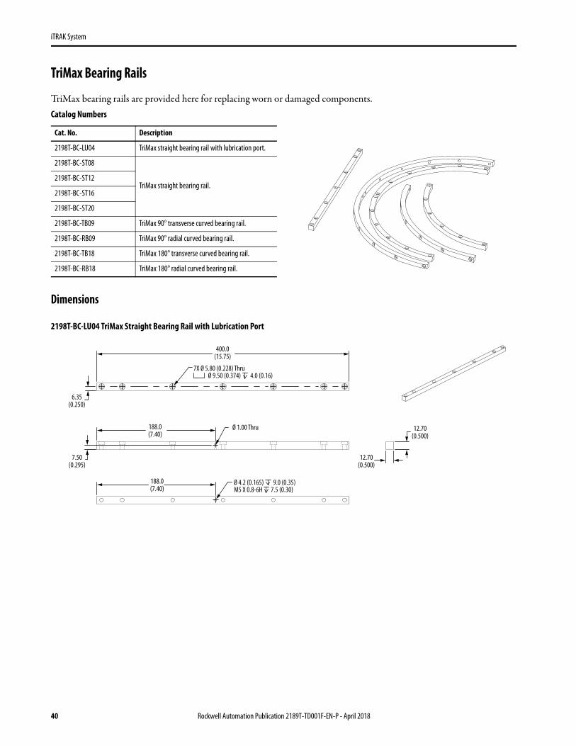
TriMax Bearing Rails
TriMax bearing rails are provided here for replacing worn or damaged components.
Dimensions
2198T-BC-LU04 TriMax Straight Bearing Rail with Lubrication Port
Catalog Numbers
Cat. No. Description
2198T-BC-LU04 TriMax straight bearing rail with lubrication port.
2198T-BC-ST08
TriMax straight bearing rail.2198T-BC-ST12
2198T-BC-ST16
2198T-BC-ST20
2198T-BC-TB09 TriMax 90° transverse curved bearing rail.
2198T-BC-RB09 TriMax 90° radial curved bearing rail.
2198T-BC-TB18 TriMax 180° transverse curved bearing rail.
2198T-BC-RB18 TriMax 180° radial curved bearing rail.
400.0(15.75)
188.0(7.40)
7X Ø 5.80 (0.228) ThruØ 9.50 (0.374) 4.0 (0.16)
6.35(0.250)
7.50(0.295)
188.0(7.40)
Ø 4.2 (0.165) 9.0 (0.35) M5 X 0.8-6H 7.5 (0.30)
Ø 1.00 Thru
12.70(0.500)
12.70(0.500)
40 Rockwell Automation Publication 2189T-TD001F-EN-P - April 2018

iTRAK System
2198T-BC-STxx TriMax Straight Bearing Rail
2198T-BC-RB09 TriMax 90°Radial Curved Rail
2198T-BC-TB09 TriMax 90° Transverse Curved Rail
A
B Ø 5.80 (0.228) ThruØ 9.50 (0.374) 4.0 (0.16)
12.70(0.500)
6.35(0.250)
12.70(0.500)
Cat. No. A mm (in.) B Number of Holes
2198T-BC-ST08 800 (31.5) 12
2198T-BC-ST12 1200 (47.2) 17
2198T-BC-ST16 1600 (63.0) 22
2198T-BC-ST20 2000 (78.7) 27
2X 2.0°
6X Ø 5.80 (0.228) ThruØ 9.50 (0.374) 4.0 (0.16)
17.20° Typical12.70
(0.500)12.70
(0.500)
R220.50(8.681)
2X 2.0°
R260.35(10.250)
17.20° Typical 12.70(0.500)
12.70(0.500)
6X 5.80 (0.228) ThruØ 9.50 (0.374) 4.0 (0.16)
Rockwell Automation Publication 2189T-TD001F-EN-P - April 2018 41

iTRAK System
2198T-BC-RB18 TriMax 180° Radial Curved Rail
2198T-BC-TB18 TriMax 90° Transverse Curved Rail
Weights
Cat. No. Weight, Approxkg (lb) Cat. No. Weight, Approx
kg (lb)
2198T-BC-LU04 0.50 (1.100) 2198T-BC-TB09 0.51 (1.124)
2198T-BC-ST08 1.00 (2.200) 2198T-BC-RB09 0.43 (0.948)
2198T-BC-ST12 1.50 (3.300) 2198T-BC-TB18 1.01 (2.227)
2198T-BC-ST16 2.00 (4.400) 2198T-BC-RB18 0.85(1.874)
2198T-BC-ST20 2.50 (5.500)
12X Ø 5.80 (0.228) ThruØ 9.50 (0.374) 4.0 (0.16)
R220.5(8.68)
2 x 2.0°
17.20° Typical
12.70(0.500)
12.70(0.500)
R260.35(10.250)
2 x 2.0°
17.20° Typical 12.70(0.500)
12.70(0.500)
12X Ø 5.80 (0.228) ThruØ 9.50 (0.374) 4.0 (0.16)
42 Rockwell Automation Publication 2189T-TD001F-EN-P - April 2018

iTRAK System
TriMax Mover Replacement Components
TriMax mover bearing components are provided for replacing worn or damaged components.
iTRAK TriMax Wheel Spare Kits
Dimensions
2198T-AV-WHL-C1 iTRAK TriMax Wheel Spare Kit
2198T-AV-WHL-C2 iTRAK TriMax Wheel Spare Kit
Cat. No. Description
2198T-AV-WHL-C1
iTRAK TriMax mover wheel replacement kit has caged cam-follower wheels with mounting studs. Each set includes 12 wheels to replace the wheels on one mover. Use this kit for the following movers.• 2198T-xT05xx-C • 2198T-xT1050-C• 2198T-xT1015-C• 2198T-xT1505-C
2198T-AV-WHL-C2
The iTRAK TriMax mover wheel replacement kit has full-complement cam-follower wheels with mounting studs. Each set includes 12 wheels to replace the wheels on one mover. Use this kit for the following movers.• 2198T-xT1015-C• 2198T-xT1510-C• 2198T-xT1515-C
12.0(0.47)
12.0(0.47)
Ø 10.0(0.39)
36.2(1.43)
13.2(0.52)
2X Ø 17.5(0.69)
Ø 26.0(1.02)
1 Set = Quantity 12 Cam-followers
5 mm (0.2 in) Socket
12.0(0.47)
12.0(0.47)
Ø 10.0(0.39)
36.2(1.43)
12.6(0.50)
2X Ø 17.5(0.69)
Ø 26.0(1.02)
1 Set = Quantity 12 Cam-followers5 mm (0.2 in) Socket
Rockwell Automation Publication 2189T-TD001F-EN-P - April 2018 43

iTRAK System
iTRAK TriMax Flexure Spare Kits
Dimensions
2198T-AV-FLX-C1 iTRAK TriMax Flexure Spare Kit
2198T-AV-FLX-C2 iTRAK TriMax Flexure Spare Kit
Weights
Cat. No. Description
2198T-AV-FLX-C1 iTRAK TriMax mover flexure replacement kit, each set includes three compliant flexures to replace the flexures on one mover. Use this kit on a 2198T-xTxx05-C mover.
2198T-AV-FLX-C2 iTRAK TriMax mover flexure replacement kit, each set includes three compliant flexures to replace the flexures on one mover. Use this kit on 2198T- xTxx10-C and 2198T-xTxx15-C
Cat. No.Weight, Approx, kg (lb)
Each Kit
2198T-AV-WHL-C1 0.057 (0.126) 0.68 (1.508)
2198T-AV-WHL-C2 0.059 (0.130) 0.71 (1.561)
2198T-AV-FLX-C1 0.06 (0.132) 0.18 (0.397)
2198T-AV-FLX-C2 0.07 (0.154) 0.21 (0.463)
26.7(1.05)
53.1(2.09) 13.0
(0.51)2X Ø 10.0
(0.39)
2X M5 x 0.8
1 Set = Quantity 3 flexures
26.3(10.51)
63.2(2.49) 13.0
(0.51)2X Ø 10.0
(0.39)
2X M5 x 0.8
1 Set = Quantity 3 flexures
44 Rockwell Automation Publication 2189T-TD001F-EN-P - April 2018

iTRAK System
TriMax Tools
These tools are available for mover removal and installation, and the replacement of mover bearing wheel and flexure, and bearing rails.
Dimensions
2198T-A03 iTRAK TriMax Mover Removal Tool
2198T-A04 iTRAK TriMax Rail Alignment Tool Kit
Cat. No. Description
2198T-A03 iTRAK TriMax mover removal tools, includes two straight rail stubs.
2198T-A04 iTRAK TriMax rail alignment tool kit, includes six clamps for rail location and rail joint alignment.
2198T-A05 iTRAK TriMax wheel pre-load tool, including two pieces; one for use with 2198T-AV-FLX-C1 flexure and one for the use with 2198T-AV-FLX-C2 flexure.
2198T-A06 iTRAK TriMax rail straightening tool, includes one 1.2 m (3.94 ft) straightening bar.
20.50(0.807)
68.00(2.677)
44.00(1.732)
304.80(12.000)
12.70(0.500)
2X Ø 9.90 (0.390) Thru All Ø 9.90 (0.390) 11.4 (0.449)
1 Set = Quantity 2 tools
Center Bore Opposite Side
155.1(6.11)
62.8(2.6)
60(2.4)
158.1(6.22)
62.8(2.6)
60(2.4)
157.9(6.22)
62.8(2.6)
66.7(2.4)
157.9(6.22)
62.8(2.6)
66.7(2.4)
Straight-to-straight Rail Alignment Clamp,
Quantity 1
Transverse Rail to Track Alignment Clamps,
Quantity 3
Right Straight-to-radial Curve Rail Alignment Clamp,
Quantity 1
Left Straight-to-radial Curve Rail Alignment Clamp,
Quantity 1
Rockwell Automation Publication 2189T-TD001F-EN-P - April 2018 45

iTRAK System
2198T-A05 iTRAK TriMax Wheel Preload Tool
2198T-A06 iTRAK TriMax Rail Straightening Tool
Weights
Cat. No. Weight, Approxkg (lb) Cat. No. Weight, Approx
kg (lb)
2198T-A03 0.36 (0.79) 2198T-A05 1.5 (3.31)
2198T-A04 1.8 (3.97) 2198T-A06 5.2 (11.46)
105.0(4.13)
175.0(6.89)
57.50(2.264)
57.50(2.264)
3X Ø 6.6 (0.26) Thru All Ø 11.0 (0.43) 6.0 (0.24)
M8x1.0 - 6H Thru
20.0(0.79)
20.0(0.79)
CL
20.0(0.79)
116.0(4.57)
175.0(6.89)
57.50(2.264)
57.50(2.264)
3X Ø 6.6 (0.26) Thru All Ø 11.0 (0.43) 6.0 (0.24)
M8x1.0 - 6H Thru
20.0(0.79)
CL
Use this wheel preload tool with on a 2198T-xTxx05-C mover with 2198T-AV-FLX-C1 flexures.
Use this wheel preload tool on 2198T-xTxx10-C and 2198T-xTxx15 movers with 2198T-AV-FLX-C2 flexures.
1200(47.2)
60.7(2.39)
33(1.3)
Straightening Bar, Quantity 1
46 Rockwell Automation Publication 2189T-TD001F-EN-P - April 2018

iTRAK System
Lubrication System
This lubrication system provides programmable lubrication pumps, mounts, and fittings to manage the lubrication that is required for your iTRAK system. The system comes with a set of straight fittings to replace the angled fittings if your system design requires them. Replacement lubricant cartridges and wipers are also available.
Lubrication System Components
2198T-AL-SYS iTRAK Lubrication System Components (1)
2198T Lubrication System
Cat. No. Component Description
2198T-AL-SYS iTRAK Lubrication System iTRAK lubrication system with three digitally activated pumps with mounting brackets, three lubricant cartridges, optional straight fitting, and 20 m (65.6 ft) of tubing.
2198T-AL-RES iTRAK Lubrication Cartridge iTRAK lubrication system replacement cartridges.
2198T-AL-PAD-V iTRAK Lubrication Wiper iTRAK lubrication wiper, vee-rail, replacement wipers for 2198T-VTxx10-A and 2198T-VTxx015-A movers, 10 pieces.
2198T-AL-PAD-V-05 iTRAK Lubrication Wiper iTRAK lubrication wiper, vee-rail, replacement wipers for 2198T-VTxx05-A movers, 10 pieces.
Item Description
1 5 m (16.4 ft) Digital signal cable
2 Digitally activated pump
3 Lubricant cartridge
4 Mounting bracket
5 Brass elbow fitting
6 Check valve
7 20 m (66 ft) of tubing
8 Straight brass fitting (1)
(1) If your installation requires the tubing to exit the pumps vertically, you can replace the brass elbows with the three straight brass nipples that are supplied with the kit.
2
4
3
5
8
6
1
7
Rockwell Automation Publication 2189T-TD001F-EN-P - April 2018 47
iTRAK System
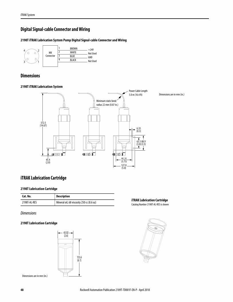
Digital Signal-cable Connector and Wiring
2198T iTRAK Lubrication System Pump Digital Signal-cable Connector and Wiring
Dimensions
2198T iTRAK Lubrication System
iTRAK Lubrication Cartridge
Dimensions
2198T Lubrication Cartridge
2198T Lubrication Cartridge
Cat. No. Description
2198T-AL-RES Mineral oil, 68 viscosity 250 cc (8.6 oz)
1
2
3
4BROWNWHITEBLUEBLACK
1234
+24VNot UsedGNDNot Used
M8Connector
45.4(2.0)
6.35(0.3)
88.9(3.5)
95.25(3.75)
63.5(3.0)
127.0(5.0)
372.5(14.67)
Minimum static bend radius 22 mm (0.87 in.)
Power Cable Length 5.0 m (16.4 ft) Dimensions are in mm (in.)
iTRAK Lubrication CartridgeCatalog Number 2198T-AL-RES is shown
155.6(6.1)
65.02(2.6)
Dimensions are in mm (in.)
48 Rockwell Automation Publication 2189T-TD001F-EN-P - April 2018
iTRAK System
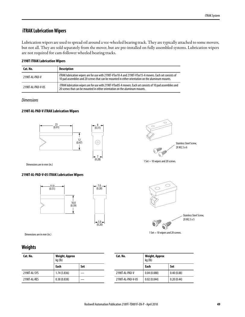
iTRAK Lubrication Wipers
Lubrication wipers are used to spread oil around a vee-wheeled bearing track. They are typically attached to some movers, but not all. They are sold separately from the mover, but are pre-installed on fully assembled systems. Lubrication wipers are not required for cam-follower wheeled bearing tracks.
Dimensions
2198T-AL-PAD-V iTRAK Lubrication Wipers
2198T-AL-PAD-V-05 iTRAK Lubrication Wipers
Weights
2198T iTRAK Lubrication Wipers
Cat. No. Description
2198T-AL-PAD-V iTRAK lubrication wipers are for use with 2198T-VTxx10-A and 2198T-VTxx15-A movers. Each set consists of 10 pad assemblies and 20 screws that can be mounted in either orientation on the aluminum mounts.
2198T-AL-PAD-V-05 iTRAK lubrication wipers are for use with 2198T-VTxx05-A movers. Each set consists of 10 pad assemblies and 20 screws that can be mounted in either orientation on the aluminum mounts.
Cat. No. Weight, Approxkg (lb)
Cat. No. Weight, Approxkg (lb)
Each Set Each Set
2198T-AL-SYS 1.74 (3.836) — 2198T-AL-PAD-V 0.04 (0.088) 0.40 (0.88)
2198T-AL-RES 0.38 (0.838) — 2198T-AL-PAD-V-05 0.02 (0.044) 0.20 (0.44)
23(0.91)
12(0.47)
8(0.31)
7(0.28)
Dimensions are in mm (in.)
Stainless Steel Screw,2X M2.5 x 6
1 Set = 10 wipers and 20 screws.
13.0(0.51)
10.0(0.39)
7.0(0.28)
5.0(0.20)
Dimensions are in mm (in.)
Stainless Steel Screw,2X M2.5 x 5
1 Set = 10 wipers and 20 screws.
Rockwell Automation Publication 2189T-TD001F-EN-P - April 2018 49

iTRAK System
Magnet Plates
Mover magnet plates can be used to build your own movers to optimize weight or bearing solutions. They are normally included in the mover. Series B magnet plates in most cases have an additional mounting hole and all are backward compatible with series A magnet plates.
2189T Magnet Plates
Cat. No.Plate Width mm (in.)
Plate Length (1) mm (in.)
(1) See mechanical drawings pages 51…54 for overall mover length.
2198T-M0505-A000
50 (1.97)
50 (1.97)
2198T-M0510-A000 100 (3.97)
2198T-M0515-A000 150 (5.91)
2198T-M1005-A000
100 (3.97)
50 (1.97)
2198T-M1010-A000 100 (3.97)
2198T-M1015-A000 150 (5.91)
2198T-M1505-A000
150 (5.91)
50 (1.97)
2198T-M1510-A000 100 (3.97)
2198T-M1515-A000 150 (5.91) L
W
Magnet Plates(catalog numbers 2198T-M0505-A000, 2198T-M1010-A000, and 2198T-M1515-A000 are shown)
50 Rockwell Automation Publication 2189T-TD001F-EN-P - April 2018

iTRAK System
Dimensions
2198T-M0505-A000 Magnet Plate - Series B
2198T-M0510-A000 Magnet Plate - Series B
2198T-M0515-A000 Magnet Plate - Series B
55.0(2.17)
4.5(0.18)
55.0(2.17)
23.0(0.91)
46.0(1.81)
6.5(0.26)
42.0(1.65)
3X M6 X 1.0
N S N
13.00(0.512)
Dimensions are in mm (in.)
55.00(2.165)
99.00 (3.898)
4.50(0.177)
46.00(1.811)
17.50(0.689)
24.50(0.964)
25.00(0.984)
50.00(1.968)
6X M6 x 1.0
4.0 x 45°
13.00(0.512)
N S N S
Dimensions are in mm (in.)
155.0(6.10)
52.50(2.066)
50.0(1.97)
25.0(0.98)
4.50(0.18)
46.00(1.81)
55.0(2.16)
4X 4.0 (0.157) X 45°
6X M6 x 1.0 (0.039) 7 (0.276)
13.00(0.512)
13.00(0.512)
N S N S N S N
Dimensions are in mm (in.)
Rockwell Automation Publication 2189T-TD001F-EN-P - April 2018 51

iTRAK System
2198T-M1005-A000 Magnet Plate - Series B
2198T-M1010-A000 Magnet Plate - Series B
55.0(2.165)
4.50(0.177)
105.0(4.13)
23.00(0.9056)
46.00(1.811)
6.50(0.256)
92.00(3.622)
3X M6 X 1.0 THRU
N S N
N S N
13.00(0.512)
Dimensions are in mm (in.)
4.50(0.177)
24.50(0.965)
25.00(0.984)
105.00(4.134)
99.00(3.898)
50.00(1.969)
96.00(3.780)
4X 4.0 (0.157) X 45°
6X M6 x 1.0 (0.039)
13.00(0.512)
42.50(1.673)
N
N
S
S
N
N
S
S
Dimensions are in mm (in.)
52 Rockwell Automation Publication 2189T-TD001F-EN-P - April 2018
iTRAK System
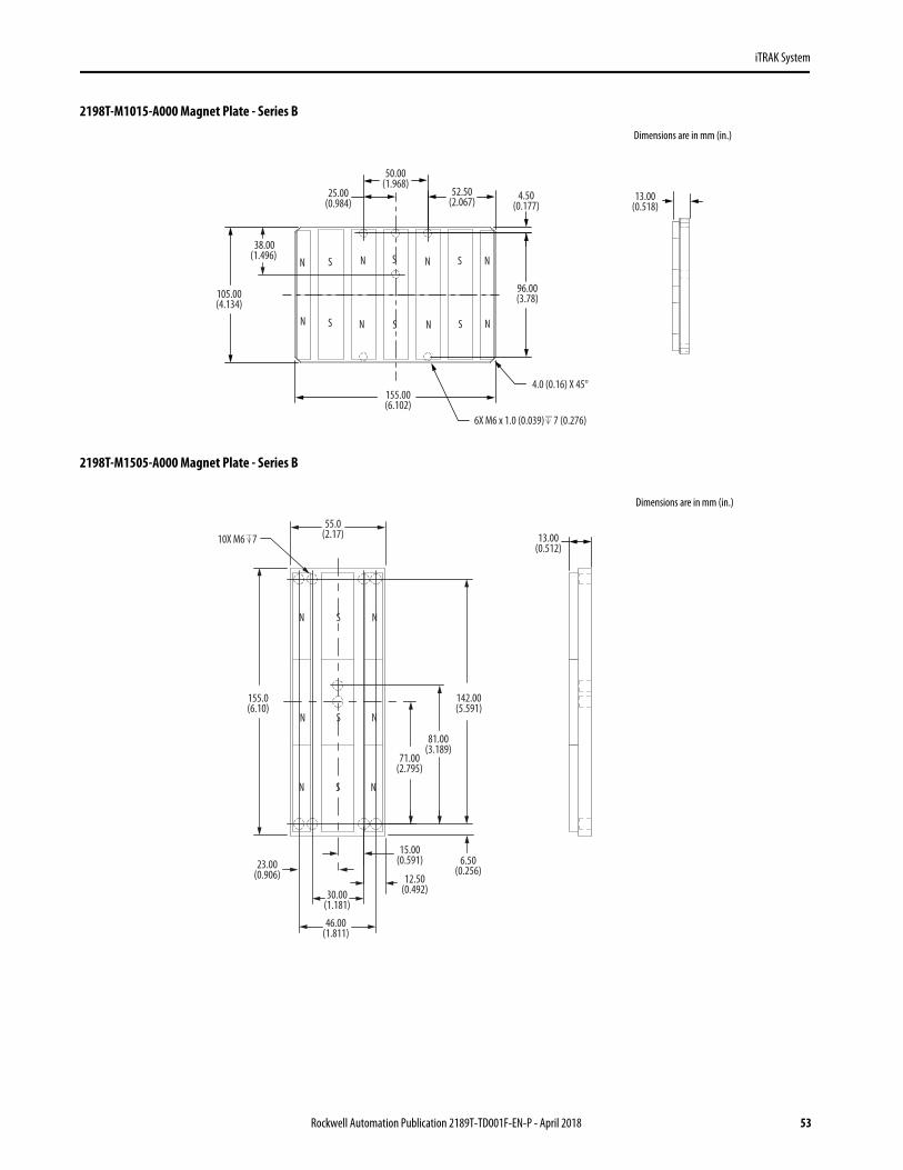
2198T-M1015-A000 Magnet Plate - Series B
2198T-M1505-A000 Magnet Plate - Series B
4.50(0.177)
96.00(3.78)
52.50(2.067)
50.00(1.968)
25.00(0.984)
105.00(4.134)
155.00(6.102)
4.0 (0.16) X 45°
13.00(0.518)
6X M6 x 1.0 (0.039) 7 (0.276)
38.00(1.496)
N S N S N S N
N S N S N S N
Dimensions are in mm (in.)
N S
N
SN
S
N
N
N
55.0(2.17)
155.0(6.10)
6.50(0.256)
71.00(2.795)
142.00(5.591)
12.50(0.492)
15.00(0.591)23.00
(0.906)
30.00(1.181)
10X M6 7 13.00(0.512)
81.00(3.189)
46.00(1.811)
Dimensions are in mm (in.)
Rockwell Automation Publication 2189T-TD001F-EN-P - April 2018 53

iTRAK System
2198T-M1510-A000 Magnet Plate - Series B
2198T-M1515-A000 Magnet Plate - Series B
N S N S
N
N
S
S
N
N
S
S
99(3.9)
146.00 (5.748 )
4.50 (0.177)
24.50(0.965)
25.00(0.984)
50.00(1.968)
155.00 (6.102)
2.0 x 45º
6X M6 x 1.0
13.00(0.512)
63.00(2.480)
Dimensions are in mm (in.)
50.0(1.97)
155.0(6.10)
4.50(0.177)
146.00(5.748)
155.0(6.1)
25.0(0.98)
52.50(2.067 )
13.00(0.512)
2.0 x 45°
6X M6 x 1.0 7
NSNSNSN
NSNSNSN
NSNSNSN
63.00(2.480)
Dimensions are in mm (in.)
54 Rockwell Automation Publication 2189T-TD001F-EN-P - April 2018

iTRAK System
Weights 2198T Magnet Plate
Cat. No. Weight, Approx kg (lb)
2198T-M0505-A000 0.28 (0.617)
2198T-M0510-A000 0.48 (1.058)
2198T-M0515-A000 0.76 (1.676)
2198T-M1005-A000 0.54 (1.190)
2198T-M1010-A000 0.94 (2.072)
2198T-M1015-A000 1.48 (3.263)
2198T-M1505-A000 0.76 (1.676)
2198T-M1510-A000 1.40 (3.086)
2198T-M1515-A000 2.20 (4.850)
Rockwell Automation Publication 2189T-TD001F-EN-P - April 2018 55

iTRAK System
Position Magnets
Position magnets are used to actuate sensors in the track. These magnets are typically sold separately from the mover, but are pre-installed on fully assembled systems.
Dimensions
2198T Position Magnet
Weights
2198T Position Magnets
Cat. No.Sensor Actuator Type (1)
(1) North and south magnet poles must alternate on the track if movers are operating below 150 mm (5.9 in.) pitch at any place on the track.
FinishMagnet Centerline Height mm (in.)
2198T-NN-318 North Black anodized31.8 (1.25)
2198T-NS-318 South Clear anodized
2198T Position Magnet
Cat. No. Weight, Approx kg (lb)
2198T-NN-3180.06 (0.132)
2198T-NS-318
Position Magnet(catalog number 2198T-Nx-318 shown)
31.8(1.25)
Mover Side ViewDimensions are in mm (in.)
19.1(0.75)
Ref.
12.7(0.50)
Ref. Mounting PlateThickness
10.0(0.39)
Ref.
12.0(0.47)
Ref.10.0
(0.39)Ref.
40.8(1.61)
Ref.
22.0(0.87)
Ref.
31.8(1.25)Configured Dimension
2X 2.5 14.0M3 x 0.5 - 6H 11 3.5 ± 0.1
(0.14 ± 0.004 )5.0 H7
Dimensions are in mm (in.)
56 Rockwell Automation Publication 2189T-TD001F-EN-P - April 2018

iTRAK System
Gateway
This generation two gateway controls and coordinates iTRAK motor modules and provides single Ethernet port for an upstream Ethernet interface to the Logix system.
Gateway Connectors
The gateway computer is dedicated to the control and coordination of the iTRAK motor modules and to provide an interface for them to the Logix system. Therefore, the only connector and ports that you can use on the gateway computer are the power input, one of the USB ports, and the Ethernet port (AMT) marked with an X. Do not use any other input or output on the gateway computer.
2198T Gateway Ports and Power Connector
2198T Gateway
Cat. No. Number of Ports
2198T-G02-016-E 16
2198T-G02-032-E 32
2198T-G02-048-E 48
2198T-G02-064-E 64
Gateway(catalog number 2198T-G02-064-E shown)
2198T-G01-016-E Gateway is shown.
24V Power Plug
Machine Ethernet connection as marked on the chassis.(1)
Power Connector Side ViewUSB Side View
The USB cable from the digital I/O can be connected to any of the USB ports on the gateway.
USB 2.0 Ports
(1) Make only this connection. Do not use any other Ethernet ports for machine Ethernet.
Rockwell Automation Publication 2189T-TD001F-EN-P - April 2018 57

iTRAK System
2198T Gateway Ports and Power Connector (Continued)
Power Connector Pinout
Pin Signal Description
1 V+ 19…26V DC
2 V- 0V DC
3 Field Ground Chassis Ground
USB 2.0 Connector Pinout
Pin Signal Description
1 VCC Power
2 DATA-USB 2.0 differential pair
3 DATA+
4 GND Ground for power return
7 6 5 4
8 9 10 11 12 13 14 15
3 2 1 0
Top View
Communication Port
2198T-G01-016-E Gateway is shown.
Top View
Terminator Plug
1 2 3
1 4
58 Rockwell Automation Publication 2189T-TD001F-EN-P - April 2018

iTRAK System
The USB 3.0 ports operate at the same rate as the USB 2.0 ports.
The AMT Ethernet port is for connection to the machine Ethernet, it is the only Ethernet port that can be used on gateway.
USB 3.0 Connector Pinout
Pin Signal Description
1 VBUS Power
2 D-USB 2.0 differential pair
3 D+
4 GND Ground for power return
5 StdA_SSRX- Super-speed receiver differential pair
6 StdA_SSRX+
7 GND_DRAIN Ground for signal return
8 StdA_SSTX- Super-speed transmitter differential pair9 StdA_SSTX+
Communication and Ethernet Port (AMT) Pinout
Pin Signal Description
1 + TX Transmit Port (+) Data Terminal
2 - TX Transmit Port (-) Data Terminal
3 + RX Receive Port (+) Data Terminal
4 — —
5 — —
6 - RX Receive Port (-) Data Terminal
7 — —
8 — —
1 2 3
56789
4
18
Ethernet Connector
Communication Connectors
18
Rockwell Automation Publication 2189T-TD001F-EN-P - April 2018 59

iTRAK System
Battery
The gateway uses a 3V BR2032 battery to maintain the BIOS settings and the system clock while the power is disconnected for a short time. Replace only with a BR2032 battery, do not use CR2032 battery as a replacement.
Battery Location
CFast Card
The gateway includes a 4 Gb CFast card to store the operating system and Logix Designer application interface software. The gateway does not have a hard drive, The CFast card in the only media storage device. If you require a replacement CFast card contact Rockwell Automation support.
CN25
CN23
CN21
CN29
CN34JP3
CN26
Battery
CN20CN21JP1
CN35
CN18
CN27CN28
CN24
CN30
CN31
CN22
CFast Card Slot
USB Side View
60 Rockwell Automation Publication 2189T-TD001F-EN-P - April 2018

iTRAK System
Gateway Status Indicators
The gateway uses the following status indicators: power, battery, and Ethernet (active and status).
Technical Specifications
Status Indicator Description
Status Indicator Status Description
Ethernet status Solid green Ethernet connection is linked
Ethernet active Blinking yellow Transmitting and receiving data
BTR Red CMOS battery has gone below 2.3V
HDD — Not used
PWRGreen Gateway is on
Yellow Gateway is in standby mode
2198T Gateway
Attribute 2198T-G02-xxx-E
Input voltage 19…26V DC
Power consumption 50 W
Surrounding air temperatureOperatingStorage
0…50 °C (32…122 °F)-30…60 °C (-22…140 °F)
Relative humidity 5…95% noncondensing
Vibration 5…55 Hz @ 0.35 mm (0.014 in.) double amplitude, continuous displacement; 55…500 Hz @ 2.0 g peak constant acceleration
Shock 15 g, 11 ms half-sine pulse (3 pulses in each direction of 3 mutually perpendicular directions)
Certification CE
BTR HDD PWRAMT
Ethernet Status Indicators
Active
Status
Power Connector Side View
Rockwell Automation Publication 2189T-TD001F-EN-P - April 2018 61

iTRAK System
Position Loop Update Rate by System Size (1)
(1) Based on firmware revision 1.108 and higher.
Mov
ers Sections
2 4 6 8 10 12 14 16 18 20 22 24 26 28 30 32 34 36 38 40 42 44 46 48 50 52 54 56 58 60 62 64
2 1 1 1 1 1 1 1 1 1 1 1 1 1 1 2 2 2 2 2 2 2 2 2 2 2 2 2 2 2 2 3 3
4 1 1 1 1 1 1 1 1 1 1 1 1 1 1 2 2 2 2 2 2 2 2 2 2 2 2 2 2 2 2 3 3
6 1 1 1 1 1 1 1 1 1 1 1 1 1 2 2 2 2 2 2 2 2 2 2 2 2 2 2 2 2 2 3 3
8 1 1 1 1 1 1 1 1 1 1 1 1 1 2 2 2 2 2 2 2 2 2 2 2 2 2 2 2 2 3 3 3
10 1 1 1 1 1 1 1 1 1 1 1 1 1 2 2 2 2 2 2 2 2 2 2 2 2 2 2 2 2 3 3 3
12 1 1 1 1 1 1 1 1 1 1 1 1 1 2 2 2 2 2 2 2 2 2 2 2 2 2 2 2 2 3 3 3
14 1 1 1 1 1 1 1 1 1 1 1 1 2 2 2 2 2 2 2 2 2 2 2 2 2 2 2 2 3 3 3 3
16 1 1 1 1 1 1 1 1 1 1 1 1 2 2 2 2 2 2 2 2 2 2 2 2 2 2 2 2 3 3 3 3
18 1 1 1 1 1 1 1 1 1 1 1 1 2 2 2 2 2 2 2 2 2 2 2 2 2 2 2 2 3 3 3 3
20 1 1 1 1 1 1 1 1 1 1 1 2 2 2 2 2 2 2 2 2 2 2 2 2 2 2 2 3 3 3 3 3
22 1 1 1 1 1 1 1 1 1 1 1 2 2 2 2 2 2 2 2 2 2 2 2 2 2 2 2 3 3 3 3 3
24 1 1 1 1 1 1 1 1 1 1 1 2 2 2 2 2 2 2 2 2 2 2 2 2 2 2 2 3 3 3 3 3
26 1 1 1 1 1 1 1 1 1 1 2 2 2 2 2 2 2 2 2 2 2 2 2 2 2 2 2 3 3 3 3 3
28 1 1 1 1 1 1 1 1 1 1 2 2 2 2 2 2 2 2 2 2 2 2 2 2 2 2 3 3 3 3 3 3
30 1 1 1 1 1 1 1 1 1 1 2 2 2 2 2 2 2 2 2 2 2 2 2 2 2 2 3 3 3 3 3 3
32 1 1 1 1 1 1 1 1 1 2 2 2 2 2 2 2 2 2 2 2 2 2 2 2 2 2 3 3 3 3 3 3
34 1 1 1 1 1 1 1 1 1 2 2 2 2 2 2 2 2 2 2 2 2 2 2 2 2 3 3 3 3 3 3 3
36 1 1 1 1 1 1 1 1 1 2 2 2 2 2 2 2 2 2 2 2 2 2 2 2 2 3 3 3 3 3 3 3
38 1 1 1 1 1 1 1 1 1 2 2 2 2 2 2 2 2 2 2 2 2 2 2 2 2 3 3 3 3 3 3 3
40 1 1 1 1 1 1 1 1 2 2 2 2 2 2 2 2 2 2 2 2 2 2 2 2 3 3 3 3 3 3 3 3
42 1 1 1 1 1 1 1 1 2 2 2 2 2 2 2 2 2 2 2 2 2 2 2 2 3 3 3 3 3 3 3 3
44 1 1 1 1 1 1 1 1 2 2 2 2 2 2 2 2 2 2 2 2 2 2 2 2 3 3 3 3 3 3 3 3
46 1 1 1 1 1 1 1 2 2 2 2 2 2 2 2 2 2 2 2 2 2 2 2 3 3 3 3 3 3 3 3 3
48 1 1 1 1 1 1 1 2 2 2 2 2 2 2 2 2 2 2 2 2 2 2 2 3 3 3 3 3 3 3 3 3
50 1 1 1 1 1 1 1 2 2 2 2 2 2 2 2 2 2 2 2 2 2 2 2 3 3 3 3 3 3 3 3 3
52 1 1 1 1 1 1 2 2 2 2 2 2 2 2 2 2 2 2 2 2 2 2 2 3 3 3 3 3 3 3 3 3
54 1 1 1 1 1 1 2 2 2 2 2 2 2 2 2 2 2 2 2 2 2 2 3 3 3 3 3 3 3 3 3 3
56 1 1 1 1 1 1 2 2 2 2 2 2 2 2 2 2 2 2 2 2 2 2 3 3 3 3 3 3 3 3 3 3
58 1 1 1 1 1 2 2 2 2 2 2 2 2 2 2 2 2 2 2 2 2 2 3 3 3 3 3 3 3 3 3 3
60 1 1 1 1 1 2 2 2 2 2 2 2 2 2 2 2 2 2 2 2 2 3 3 3 3 3 3 3 3 3 3 3
62 1 1 1 1 1 2 2 2 2 2 2 2 2 2 2 2 2 2 2 2 2 3 3 3 3 3 3 3 3 3 3 3
64 1 1 1 1 1 2 2 2 2 2 2 2 2 2 2 2 2 2 2 2 2 3 3 3 3 3 3 3 3 3 3 3
66 1 1 1 1 2 2 2 2 2 2 2 2 2 2 2 2 2 2 2 2 3 3 3 3 3 3 3 3 3 3 3 3
68 1 1 1 1 2 2 2 2 2 2 2 2 2 2 2 2 2 2 2 2 3 3 3 3 3 3 3 3 3 3 3 3
70 1 1 1 1 2 2 2 2 2 2 2 2 2 2 2 2 2 2 2 2 3 3 3 3 3 3 3 3 3 3 3 3
72 1 1 1 2 2 2 2 2 2 2 2 2 2 2 2 2 2 2 2 3 3 3 3 3 3 3 3 3 3 3 3 3
74 1 1 1 2 2 2 2 2 2 2 2 2 2 2 2 2 2 2 2 3 3 3 3 3 3 3 3 3 3 3 3 3
76 1 1 1 2 2 2 2 2 2 2 2 2 2 2 2 2 2 2 2 3 3 3 3 3 3 3 3 3 3 3 3 3
78 1 1 2 2 2 2 2 2 2 2 2 2 2 2 2 2 2 2 2 3 3 3 3 3 3 3 3 3 3 3 3 3
80 1 1 2 2 2 2 2 2 2 2 2 2 2 2 2 2 2 2 3 3 3 3 3 3 3 3 3 3 3 3 3 3
82 1 1 2 2 2 2 2 2 2 2 2 2 2 2 2 2 2 2 3 3 3 3 3 3 3 3 3 3 3 3 3 3
84 1 2 2 2 2 2 2 2 2 2 2 2 2 2 2 2 2 2 3 3 3 3 3 3 3 3 3 3 3 3 3 3
86 1 2 2 2 2 2 2 2 2 2 2 2 2 2 2 2 2 3 3 3 3 3 3 3 3 3 3 3 3 3 3 3
88 1 2 2 2 2 2 2 2 2 2 2 2 2 2 2 2 2 3 3 3 3 3 3 3 3 3 3 3 3 3 3 3
90 1 2 2 2 2 2 2 2 2 2 2 2 2 2 2 2 2 3 3 3 3 3 3 3 3 3 3 3 3 3 3 3
92 2 2 2 2 2 2 2 2 2 2 2 2 2 2 2 2 3 3 3 3 3 3 3 3 3 3 3 3 3 3 3 3
94 2 2 2 2 2 2 2 2 2 2 2 2 2 2 2 2 3 3 3 3 3 3 3 3 3 3 3 3 3 3 3 3
96 2 2 2 2 2 2 2 2 2 2 2 2 2 2 2 2 3 3 3 3 3 3 3 3 3 3 3 3 3 3 3 3
62 Rockwell Automation Publication 2189T-TD001F-EN-P - April 2018

iTRAK System
Dimensions
2198T-G02-032-E, 2198T-G02-048-E, and 2198T-G02-064-E Gateways
2198T-G02-016-E Gateway
22.8(0.90)
130.8(5.15)
238.8(9.40)
266.7(10.50)
394.4(15.53)
6.2(0.24)
388.2(15.28)
40.8(1.61)
109.1(4.29)
19.5(0.77)
227.8(8.97)
Front View
Side View
Dimensions are in mm (in.)
Ø 5.5(0.22) Through
6.4(0.25)
273.9(10.78)
280.2(11.03)
22.8(0.90)
130.8(5.15)
238.8(9.40)
266.7(10.50)
227.8(8.97)
40.8(1.61)
109.1(4.29)
19.5(0.77)Top View
Side View
Dimensions are in mm (in.)
Ø 5.5(0.22) Through
Rockwell Automation Publication 2189T-TD001F-EN-P - April 2018 63

iTRAK System
Weights 2198T Gateway
Cat. No. Weight, Approx kg (lb)
2198T-G02-016-E 3.3 (7.2)
2198T-G02-032-E 4.1 (9.0)
2198T-G02-048-E 4.2 (9.3)
2198T-G02-064-E 4.3 (9.5)
64 Rockwell Automation Publication 2189T-TD001F-EN-P - April 2018

iTRAK System
Kinetix 5700 iTRAK Power Supply and iTRAK Bus Conditioner Module
The Kinetix 5700 iTRAK power supply with 458…747V DC input provides continuous output power and current to iTRAK motor modules by using two controlled DC outputs with continuous current of 12.5 A and peak current of 25 A. The iTRAK bus conditioner module provides additional DC bus stiffness with local capacitance to the track. Use it whenever you use the iTRAK power supply unless advised by Rockwell Automation.
See Kinetix Servo Drives Specifications Technical Data, publication KNX-TD003, for complete Kinetix 5700 Servo Drive system ordering information.
Technical Specifications
Kinetix 5700 iTRAK Power Supply and iTRAK Bus Conditioner Module
Cat. No. Description
2198T-W25K-ER Kinetix 5700 iTRAK power supply
2198T-WBCMOD iTRAK bus conditioner module
Kinetix 5700 iTRAK Power Supply
Attribute 2198T-W25K-ER
Input voltage 458…747V DC
Continuous output current (per output) 12.5 A
Peak output current 25 A
Continuous power outputDC-bus output (low voltage)DC-bus output (high voltage)
4.1 kW165V DC330V DC
DC input current (1)
@ 458V DC in@ 747V DC in
(1) Because the iTRAK power supply is a DC-DC converter with a constant output rating, input current varies linearly with input voltage.
10 A6.2 A
Internal capacitance 390 μF
iTRAK Bus Conditioner Module
Attribute 2198T-WBCMOD
Input voltages 330V DC and 165V DC
Input current 16 A rms (330V), 10 A rms (165V), max
Temperature, operating 0…40 °C (32…104 °F)
Module ingress protection IP65
UL listed 61800-5-1: Adjustable Speed Electrical Power Drive Systems
Rockwell Automation Publication 2189T-TD001F-EN-P - April 2018 65

iTRAK System
Control Power Current Specifications
iTRAK power supply and other Kinetix 5700 servo drive components have different 24V DC power consumption. Factors to consider when calculating the combined current demand from your 24V DC power supply include the following:
• Catalog number for each drive in the system• Whether servo motors include the holding brake option• Whether the system includes 2198-CAPMOD-2240 capacitor modules• How many 2198T-W25K-ER iTRAK power supplies and the number of iTRAK motor modules supported
Peak Current Specifications
Load Duty-cycle Profile Example
Control Power Current Specifications
Drive Module Drive ModuleCat. No.
24V Current Per Module(Non-brake Motor) ADC
24V Current, Max(With maximum brake current)ADC
24V Inrush Current (2)
A
(2) Inrush current duration is less than 30 ms.
iTRAK Power Supply (1)
(1) These values represent only the iTRAK power supply. They exclude the iTRAK motor modules that are connected to the iTRAK power supply and also draw current from this 24V control power input. For more information regarding 24V control power requirements, see the iTRAK System User Manual, publication 2198T-UM001.
2198T-W25K-ER 1.3 N/A 2.2
Peak Duty Cycle Definition of Terms
Term Definition (1)
(1) All current values are specified as RMS.
Continuous Current Rating (ICont) The maximum value of current that can be outputted continuously.
Peak Current Rating (IPKmax) The maximum value of peak current that the drive can output. This rating is valid only for overload times less than TPKmax.
Duty Cycle (D) The ratio of time at peak to the Application Period is defined as:
Time at Peak (TPK) The time at peak current (IPK) for a given loading profile. Must be less than or equal to TPKmax.
Peak Current (IPK) The level of peak current for a given loading profile. IPK must be less than or equal to the Peak Current Rating (TPKMAX) of the drive.
Base Current (IBase) The level of current between the pulses of peak current for a given loading profile. IBase must be less than or equal to the continuous current rating (ICont) of the drive.
Loading Profile The loading profile is composed of IPK, IBase, TPK, and D (or T) values and completely specify the operation of the drive in an overload situation. These values are collectively defined as the Loading Profile of the drive.
Application Period (T) The sum of the times at IPK (TPK) and IBase.
IPK
ICont
IBase
TPKT
D = TT
PK x 100%
D = TT
PK x 100%
66 Rockwell Automation Publication 2189T-TD001F-EN-P - April 2018

iTRAK System
iTRAK Power Supply Overload (TPK < 1.0 s)
(1) Base current (IBase) and peak current (IPK) are a percentage of the continuous drive current rating (ICont).i
Power Dissipation Specifications
Use this table to size an enclosure and calculate required ventilation for your Kinetix 5700 drive system.
Maximum Motor Cable Lengths
For iTRAK systems, cables from iTRAK power supply to motor modules up to 30 m (98 ft) can be used. See Maximum iTRAK Power Supply to Motor Module Cable Length on page 13 for cable specifications.
Cat. No.Usage as % of Rated Power Output (Watts)
20% 40% 60% 80% 100%
2198T-W25K-ER 206 272 338 404 470
IMPORTANT System performance was tested at these cable lengths. These limitations also apply when meeting CE requirements.
% Base Current (I /I )
0% 60% 100%
50%
45%
40%
35%
30%
25%
20%
15%
10%
5%
0%80%20% 40%
I = 150%
I = 200%
I = 250%
Legend
Max
imum
Dut
y Cyc
le (D
)
max
Cont
PK
PK
PK
(1)
Base
Applies to 2198T-W25K-ER iTRAK power supply.
Rockwell Automation Publication 2189T-TD001F-EN-P - April 2018 67

iTRAK System
Environmental Specifications
Certifications
Kinetix 5700 iTRAK Power Supply
Attribute Operational Range Storage Range (Non-operating)
Ambient temperature 0…50 °C (32…122 °F) -40…+70 °C (-40…+158 °F)
Relative humidity 5…95% noncondensing 5…95% noncondensing
Protection class (EN 60529) IP20
Degree of pollution (EN 61800-5-1) 2
Altitude• 1500 m (4921 ft) derate 3% per 300 m (984 ft) above 1500 m• 2000 m (6562 ft) max, with corner-grounded input power• 3000 m (9843 ft) max, with non corner-grounded input power
3000 m (9843 ft) during transport
Vibration 5…55 Hz @ 0.35 mm (0.014 in.) double amplitude, continuous displacement; 55…500 Hz @ 2.0 g peak constant acceleration
Shock 15 g, 11 ms half-sine pulse (3 pulses in each direction of 3 mutually perpendicular directions)
Kinetix 5700 iTRAK Power Supply
Agency Certification (1)
(1) When product is marked, see http://www.rockwellautomation.com/global/certification/overview.page for Declarations of Conformity Certificates.
Standards
c-UL-us UL Listed to U.S. and Canadian safety standards (UL 61800-5-1, File E59272, and CSA C22.2 No 274-13).
CEEuropean Union 2004/108/EC EMC Directive compliant with EN 61800-3:2004 + A1:2012: Adjustable Speed Electrical Power Drive Systems - Part 3; EMC Product Standard including specific test methods.
European Union 2006/95/EC Low Voltage Directive compliant with EN 61800-5-1:2007 - Adjustable speed electrical power drive systems.
C-Tick
Australian Radiocommunications Act, compliant with:• Radiocommunications Act: 1992• Radiocommunications (Electromagnetic Compatibility) Standard: 2008• Radio communications Labeling (Electromagnetic Compatibility) Notice: 2008
KCKorean Registration of Broadcasting and Communications Equipment, compliant with:• Article 58-2 of Radio Waves Act, Clause 3• Registration number: KCC-REM-RAA-2198
OSHA Maximum audible noise from the servo drive system complies with OSHA standard 3074, Hearing Conservation (<85 dBA).
68 Rockwell Automation Publication 2189T-TD001F-EN-P - April 2018

iTRAK System
Dimensions
Theses drawings provide mounting dimensions iTRAK power supply and the iTRAK bus conditioner.
2198T-W25K-ER Kinetix 5700 iTRAK Power Supply
2198T-WBCMOD iTRAK Bus Conditioner Module
253(9.96)
12.0(0.47)
100(3.94)
433(17.0)
375 (14.8)
93(3.66)
Dimensions are in mm (in.)
140(5.5)
91(3.6)
93(3.7)
10(0.4)
120(4.7)
140(5.5)
1500(59.0)
Ø 15.19 ± 0.51(Ø 0.598 ± 0.02)
127.0 mm (5.0 in.)
M6 x 1, 30 mmMounting Screws (X4)
Dimensions are in mm (in.)
Rockwell Automation Publication 2189T-TD001F-EN-P - April 2018 69

iTRAK System
Weights
Power Cable - iTRAK Power Supply
Dimensions
2198T-CHBP8S8-12xx Power Cable
Kinetix 5700 iTRAK Power Supply and iTRAK Bus Conditioner
Cat. No.Weight, Approxkg (lb)
2198T-W25K-ER 7.60 (16.8)
2198T-WBCMOD 2.7 (5.96)
Power Cables - iTRAK Power Supply
Cat. No.Length m (ft)
Control Power Conductormm2 (AWG)
Buss Power Conductormm2 (AWG)
Down Stream Connector
UpstreamConnector
Cable Type
2198T-CHBFLS8-12AA06 6 (19.7)
2.08 (14) 3.31 (12) M23 - Female Flying LeadHybrid Main and Control Power
2198T-CHBFLS8-12AA09 9 (29.5)
2198T-CHBFLS8-12AA12 12 (39.4)
2198T-CHBFLS8-12AA15 15 (49.2)
2198T-CHBFLS8-12AA30 30 (98.4)
Power Cable (catalog number2198T-CHBP8S8-12AAxx shown)
113 ± 2(4.4 ± 0.08) 78
(3.1)28
(1.1)Ø 14.25 ± 0.51(Ø 0.561 ± 0.02)
72.0 mm (2.8 in.) Bend Radius
Dimensions are in mm (in.)
70 Rockwell Automation Publication 2189T-TD001F-EN-P - April 2018

iTRAK System
Communication Cables
The following table shows the standard serial-communication cord sets for the iTRAK system. The cord sets are terminated with RJ-45 and right angle 8-wire A-Code M12 connectors.
Dimensions
2198T-CC-xx Communication Cable
2198T Communication Cable
Cat. No. Length m (ft)
2198T-CC-01 1 (3.3)
2198T-CC-02 2 (6.6)
2198T-CC-03 3 (9.9)
2198T-CC-04 4 (13.1)
2198T-CC-05 5 (16.4)
2198T-CC-06 6 (19.7)
2198T-CC-08 8 (26.2)
2198T-CC-09 9 (29.5)
2198T-CC-10 10 (32.8)
2198T-CC-12 12 (39.4)
2198T-CC-15 15 (49.2)
Communication Cable (catalog number 2198T-CC-01 shown)
40.0(1.58)
P1
Ø15.0 (0.59)M12 x 1
46.0 (1.81)38.0 (1.50)
Ø 7.7 (0.30)
37.0 mm (1.5 in.) Bend Radius
38.0 (1.50) Ref Shielded
15.0 (0.59)Ref
14.0 (0.55)Ref
P2
Dimensions are in mm (in.)
Rockwell Automation Publication 2189T-TD001F-EN-P - April 2018 71

iTRAK System
Mounting Options
iTRAK systems can be mounted in few orientations. In any orientation, the top of the system is defined as the top of the mover as shown the Horizontal Mounting Orientation (H) figure.
Horizontal Mounting Orientation (H)
Vertical Mounting Orientation (V)
Stand-up Mounting Orientation (S)
Track Top
Track Bottom
Mover Top
Mover Bottom
72 Rockwell Automation Publication 2189T-TD001F-EN-P - April 2018

iTRAK System
Mover and Magnet Plate Specifications• Force specification ±10% unless otherwise stated.
• The maximum acceleration for a 2198T-VTxxxx-x mover is limited to 39.2 m/s2 (4.0 g).
Straight and Curved Motor Module Mover to Mover Pitch
Mover Cat. No.Magnet PlateCat. No.
Magnet Width mm (in.)
Magnet Length (1) mm (in.)
(1) See mechanical drawing for overall mover length.
Magnetic Attraction Straights(2)
N (lbf)
(2) At standard mechanical air gap.
Magnetic Attraction Curves (2)
N (lbf)
Straight Motor-module Minimum Mover to Mover Pitch (3) A mm (in.)
(3) Pitch is measured at the center line of the mover.
Curved Motor Module Minimum Mover to Mover Pitch (3)
B°
2198T-VT0505-x 2198T-M0505-A000
50 (1.97)
50 (1.97) 410 (92) 350 (79) 72.20 (2.843) 19°
2198T-VT0510-x 2198T-M0510-A000 100 (3.97) 820 (184) 570 (128) 103.20 (4.063) 23°
2198T-VT0515-x 2198T-M0515-A000 150 (5.91) 1250 (281) 610 (137) 165.20 (6.504) 34°
2198T-VT1005-x 2198T-M1005-A000
100 (3.97)
50 (1.97) 820 (184) 700 (157) 72.20 (2.843) 19°
2198T-VT1010-x 2198T-M1010-A000 100 (3.97) 1640 (369) 1140 (256) 103.20 (4.063) 23°
2198T-VT1015-x 2198T-M1015-A000 150 (5.91) 2510 (564) 1220 (274) 165.20 (6.504) 34°
2198T-VT1505-x 2198T-M1505-A000
150 (5.91)
50 (1.97) 1220 (274) 1040 (234) 72.20 (2.843) 19°
2198T-VT1510-x 2198T-M1510-A000 100 (3.97) 2460 (553) 1710 (384) 103.20 (4.063) 23°
2198T-VT1515-x 2198T-M1515-A000 150 (5.91) 3760 (845) 1830 (411) 165.20 (6.504) 34°
B
A
Straight Pitch Curved Pitch
Rockwell Automation Publication 2189T-TD001F-EN-P - April 2018 73

iTRAK System
Environmental Specifications
Certifications
System Level Certifications• EN 60204-1:2006/A1:2009, Safety of machinery - Electrical Equipment of Machines - Part 1: General
requirements• EN 61800-3: 2004, Adjustable Speed Electrical Power Drive Systems - Part 3 EMC Requirements• EN ISO-13849-1 Safety of Machinery - Safety - related parts of control system - Part 1: General principle of
design
Module Level Certifications• UL Listed, XDNZ: Electronically Protected Motors with Integral Controllers for Industrial Use• EN 60034-1: 2004, Rotating electrical machines. Part 1 Rating and Performance• EN 60204-1:2006/A1:2009, Safety of machinery - Electrical Equipment of Machines - Part 1: General
requirements
System Level
Attribute Value
Ambient temperature 0…40 °C (32…104 °F)
Storage temperature -30…70 °C (-22…+158 °F)
Relative humidity 5…95% non-condensing
Motor Module
Attribute Value
Liquid / dust protection IP65
Vibration 5…55 Hz @ 0.35 mm (0.014 in.) double amplitude, continuous displacement; 55…500 Hz @ 2.0-g peak constant acceleration
Shock 15 g, 11-ms half-sine pulse (3 pulses in each direction of 3 mutually perpendicular directions)
74 Rockwell Automation Publication 2189T-TD001F-EN-P - April 2018
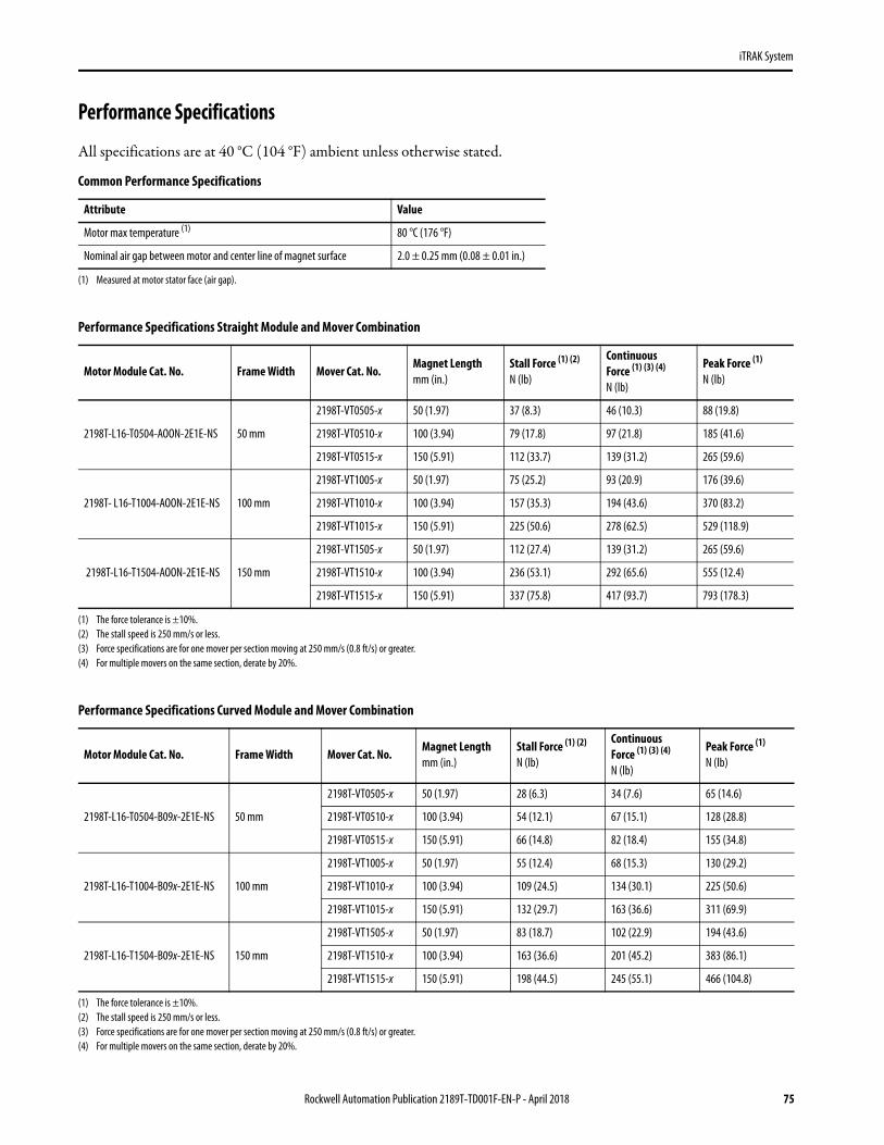
iTRAK System
Performance Specifications
All specifications are at 40 °C (104 °F) ambient unless otherwise stated.
Common Performance Specifications
Attribute Value
Motor max temperature (1)
(1) Measured at motor stator face (air gap).
80 °C (176 °F)
Nominal air gap between motor and center line of magnet surface 2.0 ± 0.25 mm (0.08 ± 0.01 in.)
Performance Specifications Straight Module and Mover Combination
Motor Module Cat. No. Frame Width Mover Cat. No.Magnet Lengthmm (in.)
Stall Force (1) (2)
N (lb)
(1) The force tolerance is ±10%.(2) The stall speed is 250 mm/s or less.
Continuous Force (1) (3) (4)
N (lb)
(3) Force specifications are for one mover per section moving at 250 mm/s (0.8 ft/s) or greater. (4) For multiple movers on the same section, derate by 20%.
Peak Force (1) N (lb)
2198T-L16-T0504-AOON-2E1E-NS 50 mm
2198T-VT0505-x 50 (1.97) 37 (8.3) 46 (10.3) 88 (19.8)
2198T-VT0510-x 100 (3.94) 79 (17.8) 97 (21.8) 185 (41.6)
2198T-VT0515-x 150 (5.91) 112 (33.7) 139 (31.2) 265 (59.6)
2198T- L16-T1004-AOON-2E1E-NS 100 mm
2198T-VT1005-x 50 (1.97) 75 (25.2) 93 (20.9) 176 (39.6)
2198T-VT1010-x 100 (3.94) 157 (35.3) 194 (43.6) 370 (83.2)
2198T-VT1015-x 150 (5.91) 225 (50.6) 278 (62.5) 529 (118.9)
2198T-L16-T1504-AOON-2E1E-NS 150 mm
2198T-VT1505-x 50 (1.97) 112 (27.4) 139 (31.2) 265 (59.6)
2198T-VT1510-x 100 (3.94) 236 (53.1) 292 (65.6) 555 (12.4)
2198T-VT1515-x 150 (5.91) 337 (75.8) 417 (93.7) 793 (178.3)
Performance Specifications Curved Module and Mover Combination
Motor Module Cat. No. Frame Width Mover Cat. No.Magnet Length mm (in.)
Stall Force (1) (2)
N (lb)
(1) The force tolerance is ±10%.(2) The stall speed is 250 mm/s or less.
ContinuousForce (1) (3) (4)
N (lb)
(3) Force specifications are for one mover per section moving at 250 mm/s (0.8 ft/s) or greater. (4) For multiple movers on the same section, derate by 20%.
Peak Force (1)
N (lb)
2198T-L16-T0504-B09x-2E1E-NS 50 mm
2198T-VT0505-x 50 (1.97) 28 (6.3) 34 (7.6) 65 (14.6)
2198T-VT0510-x 100 (3.94) 54 (12.1) 67 (15.1) 128 (28.8)
2198T-VT0515-x 150 (5.91) 66 (14.8) 82 (18.4) 155 (34.8)
2198T-L16-T1004-B09x-2E1E-NS 100 mm
2198T-VT1005-x 50 (1.97) 55 (12.4) 68 (15.3) 130 (29.2)
2198T-VT1010-x 100 (3.94) 109 (24.5) 134 (30.1) 225 (50.6)
2198T-VT1015-x 150 (5.91) 132 (29.7) 163 (36.6) 311 (69.9)
2198T-L16-T1504-B09x-2E1E-NS 150 mm
2198T-VT1505-x 50 (1.97) 83 (18.7) 102 (22.9) 194 (43.6)
2198T-VT1510-x 100 (3.94) 163 (36.6) 201 (45.2) 383 (86.1)
2198T-VT1515-x 150 (5.91) 198 (44.5) 245 (55.1) 466 (104.8)
Rockwell Automation Publication 2189T-TD001F-EN-P - April 2018 75
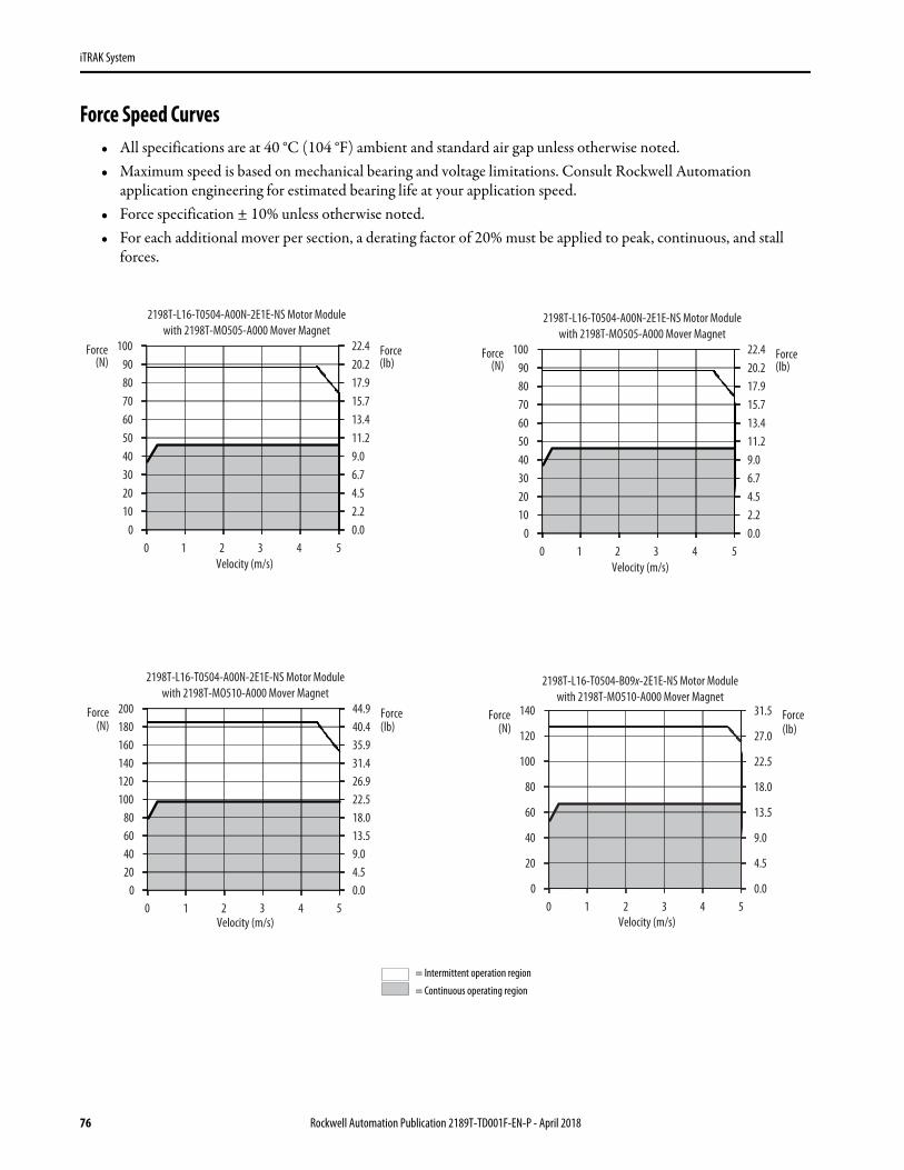
iTRAK System
Force Speed Curves• All specifications are at 40 °C (104 °F) ambient and standard air gap unless otherwise noted.• Maximum speed is based on mechanical bearing and voltage limitations. Consult Rockwell Automation
application engineering for estimated bearing life at your application speed.• Force specification ± 10% unless otherwise noted.• For each additional mover per section, a derating factor of 20% must be applied to peak, continuous, and stall
forces.
0.02.24.56.79.011.213.415.717.920.222.4
0102030405060708090
100
0 1 2 3 4 5
Force(lb)
Force (N)
Velocity (m/s)
2198T-L16-T0504-A00N-2E1E-NS Motor Modulewith 2198T-MO505-A000 Mover Magnet
0.02.24.56.79.011.213.415.717.920.222.4
0102030405060708090
100
0 1 2 3 4 5
Force(lb)
Force (N)
Velocity (m/s)
2198T-L16-T0504-A00N-2E1E-NS Motor Modulewith 2198T-MO505-A000 Mover Magnet
0.04.59.013.518.022.526.931.435.940.444.9
020406080
100120140160180200
0 1 2 3 4 5
Force(lb)
Force(N)
Velocity (m/s)
2198T-L16-T0504-A00N-2E1E-NS Motor Modulewith 2198T-MO510-A000 Mover Magnet
0.0
4.5
9.0
13.5
18.0
22.5
27.0
31.5
0
20
40
60
80
100
120
140
0 1 2 3 4 5
Force(lb)
Force(N)
Velocity (m/s)
2198T-L16-T0504-B09x-2E1E-NS Motor Modulewith 2198T-MO510-A000 Mover Magnet
= Intermittent operation region
= Continuous operating region
76 Rockwell Automation Publication 2189T-TD001F-EN-P - April 2018

iTRAK System
0.0
9.0
18.0
27.0
36.0
45.0
54.0
62.9
0
40
80
120
160
200
240
280
0 1 2 3 4 5
Force(lb)
Force(N)
Velocity (m/s)
2198T-L16-T0504-A00N-2E1E-NS Motor Modulewith 2198T-MO515-A000 Mover Magnet
0
4.5
9
13.5
18
22.5
27
31.5
36
40.5
0
20
40
60
80
100
120
140
160
180
0 1 2 3 4 5
Force(lb)
Force(N)
Velocity (m/s)
2198T-L16-T0504-B09x-2E1E-NS Motor Modulewith 2198T-MO515-A000 Mover Magnet
0.04.59.013.518.022.526.931.435.940.444.9
020406080
100120140160180200
0 1 2 3 4 5
Force(lb)
Force(N)
Velocity (m/s)
2198T-L16-T1004-A00N-2E1E-NS Motor Modulewith 2198T-M1005-A000 Mover Magnet
0.0
4.5
9.0
13.5
18.0
22.5
26.9
31.4
0
20
40
60
80
100
120
140
0 1 2 3 4 5
Force(lb)
Force(N)
Velocity (m/s)
2198T-L16-T1004-B09x-2E1E-NS Motor Modulewith 2198T-M1005-A000 Mover Magnet
0.09.018.027.036.045.054.063.072.081.090.0
04080
120160200240280320360400
0 1 2 3 4 5
Force(lb)
Force(N)
Velocity (m/s)
2198T-L16-T1004-A00N-2E1E-NS Motor Modulewith 2198T-M1010-A000 Mover Magnet
0.0
9.0
18.0
27.0
36.0
45.0
53.9
62.9
0
40
80
120
160
200
240
280
0 1 2 3 4 5
Force(lb)
Force(N)
Velocity (m/s)
2198T-L16-T1004-B09x-2E1E-NS Motor Modulewith 2198T-M1010-A000 Mover Magnet
= Intermittent operation region
= Continuous operating region
Rockwell Automation Publication 2189T-TD001F-EN-P - April 2018 77

iTRAK System
0.013.527.040.453.967.480.994.4107.8121.3134.8
060
120180240300360420480540600
0 1 2 3 4 5
Force(lb)
Force(N)
Velocity (m/s)
2198T-L16-T1004-A00N-2E1E-NS Motor Modulewith 2198T-M1015-A000 Mover Magnet
0.0
9.0
18.0
27.0
36.0
45.0
54.0
63.0
72.0
81.0
0
40
80
120
160
200
240
280
320
360
0 1 2 3 4 5
Force(lb)
Force(N)
Velocity (m/s)
2198T-L16-T1004-B09x-2E1E-NS Motor Modulewith 2198T-M1015-A000 Mover Magnet
0.0
9.0
18.0
27.0
36.0
45.0
54.0
63.0
0
40
80
120
160
200
240
280
0 1 2 3 4 5
Force(lb)
Force(N)
Velocity (m/s)
2198T-L16-T1504-A00N-2E1E-NS Motor Modulewith 2198T-M1505-A000 Mover Magnet
0.0
6.7
13.5
20.2
27.0
33.7
40.4
47.2
0
30
60
90
120
150
180
210
0 1 2 3 4 5
Force(lb)
Force(N)
Velocity (m/s)
2198T-L16-T1504-B09x-2E1E-NS Motor Modulewith 2198T-M1505-A000 Mover Magnet
0.013.527.040.554.067.581.094.5108.0121.5135.0
060
120180240300360420480540600
0 1 2 3 4 5
Force(lb)
Force(N)
Velocity (m/s)
2198T-L16-T1504-A00N-2E1E-NS Motor Modulewith 2198T-M1510-A000 Mover Magnet
0.011.222.433.644.856.067.278.489.6100.8112.0
050
100150200250300350400450500
0 1 2 3 4 5
Force(lb)
Force(N)
Velocity (m/s)
2198T-L16-T1504-B09x-2E1E-NS Motor Modulewith 2198T-M1510-A000 Mover Magnet
= Intermittent operation region
= Continuous operating region
78 Rockwell Automation Publication 2189T-TD001F-EN-P - April 2018

iTRAK System
0.0
22.5
45.0
67.4
89.9
112.4
134.9
157.4
179.8
202.3
0
100
200
300
400
500
600
700
800
900
0 1 2 3 4 5
Force(lb)
Force(N)
Velocity (m/s)
2198T-L16-T1504-A00N-2E1E-NS Motor Modulewith 2198T-M1515-A000 Mover Magnet
0.011.222.433.644.856.067.278.489.6100.8112.0
050
100150200250300350400450500
0 1 2 3 4 5
Force(lb)
Force(N)
Velocity (m/s)
2198T-L16-T1504-B09x-2E1E-NS Motor Modulewith 2198T-M1515-A000 Mover Magnet
= Intermittent operation region
= Continuous operating region
Rockwell Automation Publication 2189T-TD001F-EN-P - April 2018 79
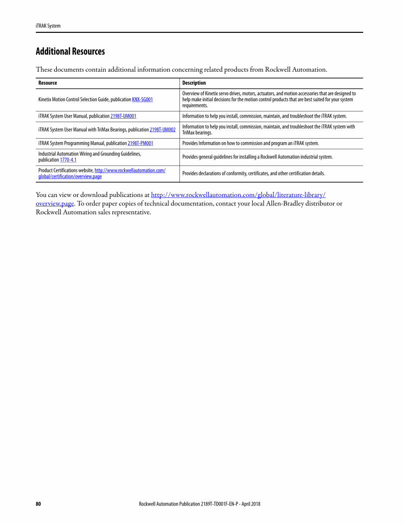
iTRAK System
Additional Resources
These documents contain additional information concerning related products from Rockwell Automation.
You can view or download publications at http://www.rockwellautomation.com/global/literature-library/overview.page. To order paper copies of technical documentation, contact your local Allen-Bradley distributor or Rockwell Automation sales representative.
Resource Description
Kinetix Motion Control Selection Guide, publication KNX-SG001Overview of Kinetix servo drives, motors, actuators, and motion accessories that are designed to help make initial decisions for the motion control products that are best suited for your system requirements.
iTRAK System User Manual, publication 2198T-UM001 Information to help you install, commission, maintain, and troubleshoot the iTRAK system.
iTRAK System User Manual with TriMax Bearings, publication 2198T-UM002 Information to help you install, commission, maintain, and troubleshoot the iTRAK system with TriMax bearings.
iTRAK System Programming Manual, publication 2198T-PM001 Provides Information on how to commission and program an iTRAK system.
Industrial Automation Wiring and Grounding Guidelines, publication 1770-4.1 Provides general guidelines for installing a Rockwell Automation industrial system.
Product Certifications website, http://www.rockwellautomation.com/global/certification/overview.page Provides declarations of conformity, certificates, and other certification details.
80 Rockwell Automation Publication 2189T-TD001F-EN-P - April 2018
iTRAK System
Notes:
Rockwell Automation Publication 2189T-TD001F-EN-P - April 2018 81

Allen-Bradley, CompactLogix, ControlLogix, iTRAK, Kinetix, LISTEN. THINK. SOLVE., Rockwell Automation, Rockwell Software, Studio 5000 Automation Engineering & Design Environment, Studio 5000 Logix Designer, and TriMax are trademarks of Rockwell Automation, Inc.Trademarks not belonging to Rockwell Automation are property of their respective companies.
Publication 2189T-TD001F-EN-P - April 2018
Rockwell Automation SupportUse the following resources to access support information.
Documentation FeedbackYour comments will help us serve your documentation needs better. If you have any suggestions on how to improve this document, complete the How Are We Doing? form at http://literature.rockwellautomation.com/idc/groups/literature/documents/du/ra-du002_-en-e.pdf.
Technical Support Center Knowledgebase Articles, How-to Videos, FAQs, Chat, User Forums, and Product Notification Updates. www.rockwellautomation.com/knowledgebase
Local Technical Support Phone Numbers Locate the phone number for your country. www.rockwellautomation.com/global/support/get-support-now.page
Direct Dial CodesFind the Direct Dial Code for your product. Use the code to route your call directly to a technical support engineer.
www.rockwellautomation.com/global/support/direct-dial.page
Literature Library Installation Instructions, Manuals, Brochures, and Technical Data. www.rockwellautomation.com/literature
Product Compatibility and Download Center (PCDC)
Get help determining how products interact, check features and capabilities, and find associated firmware.
www.rockwellautomation.com/global/support/pcdc.page
Rockwell Otomasyon Ticaret A.Ş., Kar Plaza İş Merkezi E Blok Kat:6 34752 İçerenköy, İstanbul, Tel: +90 (216) 5698400
Rockwell Automation maintains current product environmental information on its website at http://www.rockwellautomation.com/rockwellautomation/about-us/sustainability-ethics/product-environmental-compliance.page.
Supersedes Publication 2198T-TD001E-EN-P - December 2017 Copyright © 2018 Rockwell Automation, Inc. All rights reserved. Printed in the U.S.A.
Top Related