


Languages
Pages
Legal


IPSR (Integrated Photonic Systems Road mapping) GroupiNEMI-IPSR Board-Level Optical Interconnect Project
Project Leader: Tom Marrapode, Molex
iNEMI Staff: David Godlewski, Bob Pfahl
June 13-14, 2018
Recording (available for up to 6 months after webinar):https://inemi.webex.com/inemi/ldr.php?RCID=5ba8dd96b378aced3880e8ac3de2d08b

AIM Photonics Proprietary and Confidential 1
Project Overview
• The assessment of the performance of prototypes of board-level interconnect systems based on single-mode (SM) fiber, expanded-beam optical coupling, and silicon photonics transceivers. This activity will allow evaluation of existing and developing components, and thereby will identify gaps in the board-level technologies needed for practical implementation.
Need Being Addressed:
• This need was one of three identified in
the 2016 Roadmap as being critical to
the wide spread implementation of
board level integrated photonic
systems. The team has met weekly
this fall to develop this self-funded
project to address the need.
Proposed Solution:
• This solution is dependent on all
participants honoring the
commitments they have made to the
project
• Participants will be required to sign a
statement of work (SOW) and IP
Agreement.
Funding
• This project is self-funded by the
industrial participants
Constraints:
Timeline:• One Year (2017)
Specific Component and System
Characterizations
• Connector loss
• Wavelength dependence of connector loss
• Connector return loss
• Connector polarization-dependent loss
• Connector re-mating loss variation
• Signal Bit Error Rate vs. connector number and loss (up to 25
Gbps/channel)
Additional Proposed Testing :
• Dust contamination induced connector loss (Test TBD)
• Environment Thermal Aging, Humidity Aging, Thermal Cycling, and
Humidity/Condensation Cycling testing
2

Participants
Affiliation Participant Title Proposed Contributions
Molex Tom Marrapode,
IPSR Project Leader
Director of Advanced
Technology Development
Interconnects; backplane, front panel, I/O and cables
Prototype single mode expanded beam MT ferrules
Celestica Tatiana Berdinskikh Principal Optical Engineer Rack Hardware
Juniper
Networks
Valery KugelDistinguished Engineer
Link test parameters and performance evaluation
In house testing
US Conec Darrel Childers
Sharon Lutz
Director of Development
Product Manager
Prototype single mode expanded beam MT ferrules.
Interconnects; backplane, front panel, I/O
3M Company Terry Smith Senior Staff Scientist Organizer-Planning for next phases
US Competitors John Mac Williams Principle Advisor-Planning for next phases
MIT Kazumi Wada Professor Advisor-Planning for next phases
Senko Tiger Ninomiya Business Development Prototype expanded core fiber MT
Fraunhofer Dr. Henning Schröder Group Leader Optical
Interconnection
Observer for next phases
IPSR Robert Pfahl Director of Roadmapping Facilitator-Planning for next phases
iNEMI Dave Godlewski Manager of Deployment Project Facilitator
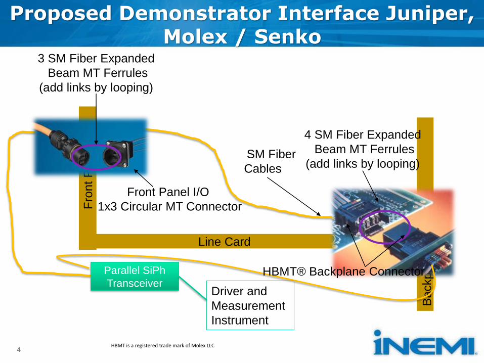
Proposed Demonstrator Interface Juniper, Molex / Senko
4
Line Card
Backpla
ne
4 SM Fiber Expanded
Beam MT Ferrules
(add links by looping)SM Fiber
Cables
Fro
nt P
anel
3 SM Fiber Expanded
Beam MT Ferrules
(add links by looping)
Front Panel I/O
1x3 Circular MT Connector
Parallel SiPh
TransceiverHBMT® Backplane Connector
Driver and
Measurement
Instrument
HBMT is a registered trade mark of Molex LLC

Proposed Demonstrator Interface, Juniper, USCONEC
5
Line Card
Ba
ckpla
ne
MXC® Backplane Connector
6 SM Fiber Expanded
Beam MT Ferrules
(add links by looping)SM Fiber
Cables
Fro
nt P
anel
1 SM Fiber Expanded
Beam MT Ferrules
Front Panel I/O
MXC Adaptor
Parallel SiPh
Transceiver
Driver and
Measurement
InstrumentMXC is a registered trade mark of US Conec Ltd.

Optical Cabling Detail View
6
Line Card
Bac
kpla
ne
Backplane ConnectorBody 4 or 6 mated ferrules
SM Fiber ExpandedBeam MT Ferrules
(add links by looping)SM FiberCables
Fro
nt
Pan
el
SM Fiber ExpandedBeam MT Ferrules
Front Panel I/O Adaptor Body
SiPh TRX
1-8 1-8
1-8
1-8
1-8
1-8
L=3M
L=3M
L=1M
L=1M
L=3M
L=3M loop back L=3M loop back
MTP®-PRO (allows male/female and key change)
MTP-PRO (allows male/female and key change)
IL/RL Test Set
SM Expanded Beam MT Ferrule
MTP is a registered trade mark of US Conec Ltd.
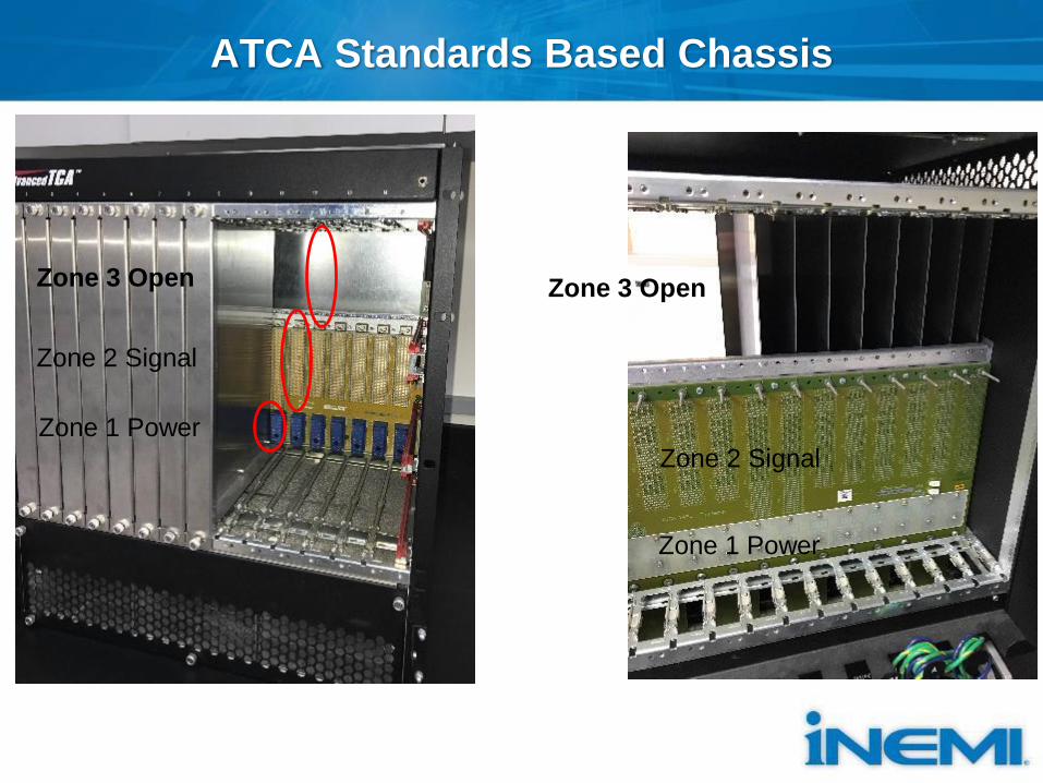
ATCA Standards Based Chassis
Zone 1 Power
Zone 2 Signal
Zone 3 Open
Zone 1 Power
Zone 2 Signal
Zone 3 Open

ATCA Chassis
Front View
HBMT MXC
Back View
HBMTMXC
MXC Circular MT

ATCA Chassis
HBMT Inside View MXC Inside View
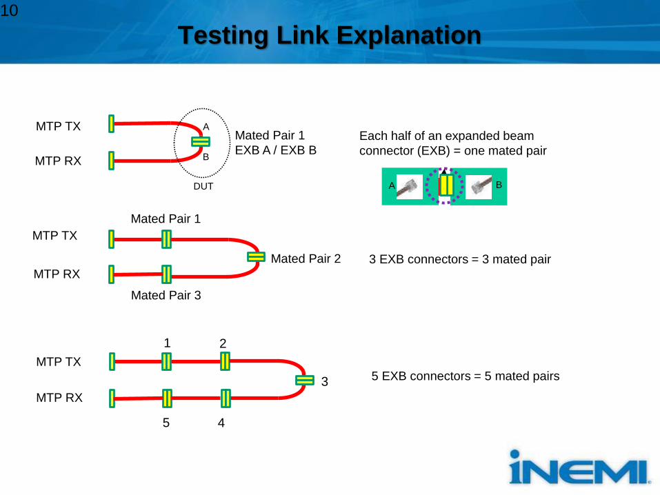
Testing Link Explanation
Mated Pair 1
EXB A / EXB B
MTP TX
MTP RX
Mated Pair 1
Each half of an expanded beam
connector (EXB) = one mated pair
3 EXB connectors = 3 mated pair
5 EXB connectors = 5 mated pairs
MTP TX
MTP RX
MTP TX
MTP RX
10
Mated Pair 2
Mated Pair 3
A
B
1 2
3
45
DUT A B

IL/RL Setup
• Based on JDSU MAP-200 with integrating sphere, 2 24x optical
switches. Bi-directional IL/integral RL measurements at
1310/1490/1550/1625nm.
JDSU MAP-200 DUT1x12 MTP Elite
FC/APC
3m SMF
Reference cables
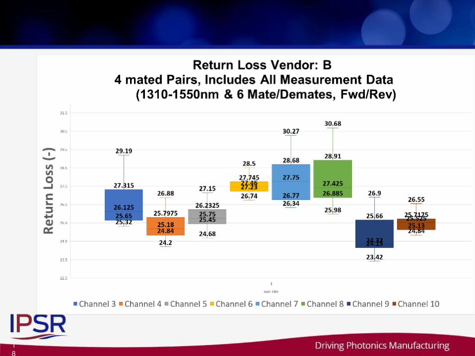
RL is measured using integration
method (integral of reflected signal
1m from MTP connectors on both
sides of the DUT) All reported data
includes both measurements
1x12 MTP Elite
SW
1S
W2
F
MFC/APC
FC/APC
5m
FC/APC
5m
3m SMF
FC/APC to FC/APC are 5m cables;
FC/APC to 1x12 MT are 3m cables
11
Dfwd
Drev
Test set allows bi-directional
measurements allowing for reversal
of optical signal. ) All reported data
includes both measurements
RL 1
RL 2
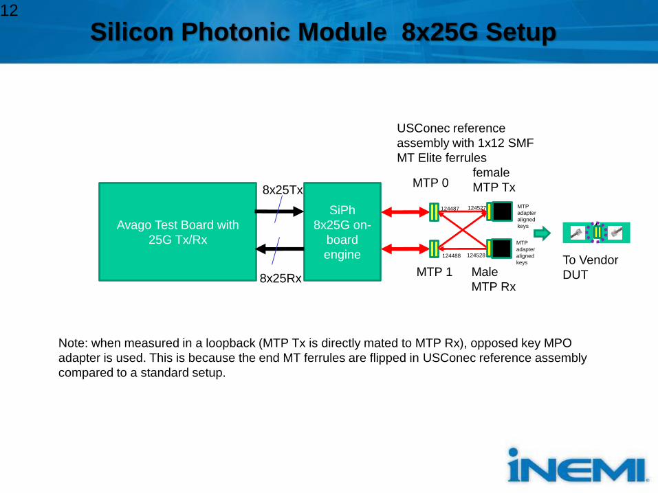
Silicon Photonic Module 8x25G Setup
Avago Test Board with
25G Tx/Rx
SiPh
8x25G on-
board
engine
MTP 0
MTP 1
female
MTP Tx
Male
MTP Rx
124487
124488
124527
124528
USConec reference
assembly with 1x12 SMF
MT Elite ferrules
8x25Rx
8x25TxMTP
adapter
aligned
keys
MTP
adapter
aligned
keys
12
To Vendor
DUT
Note: when measured in a loopback (MTP Tx is directly mated to MTP Rx), opposed key MPO
adapter is used. This is because the end MT ferrules are flipped in USConec reference assembly
compared to a standard setup.
1
3

1
4
1
5

1
6

1
7
1
8
1
9

2
0
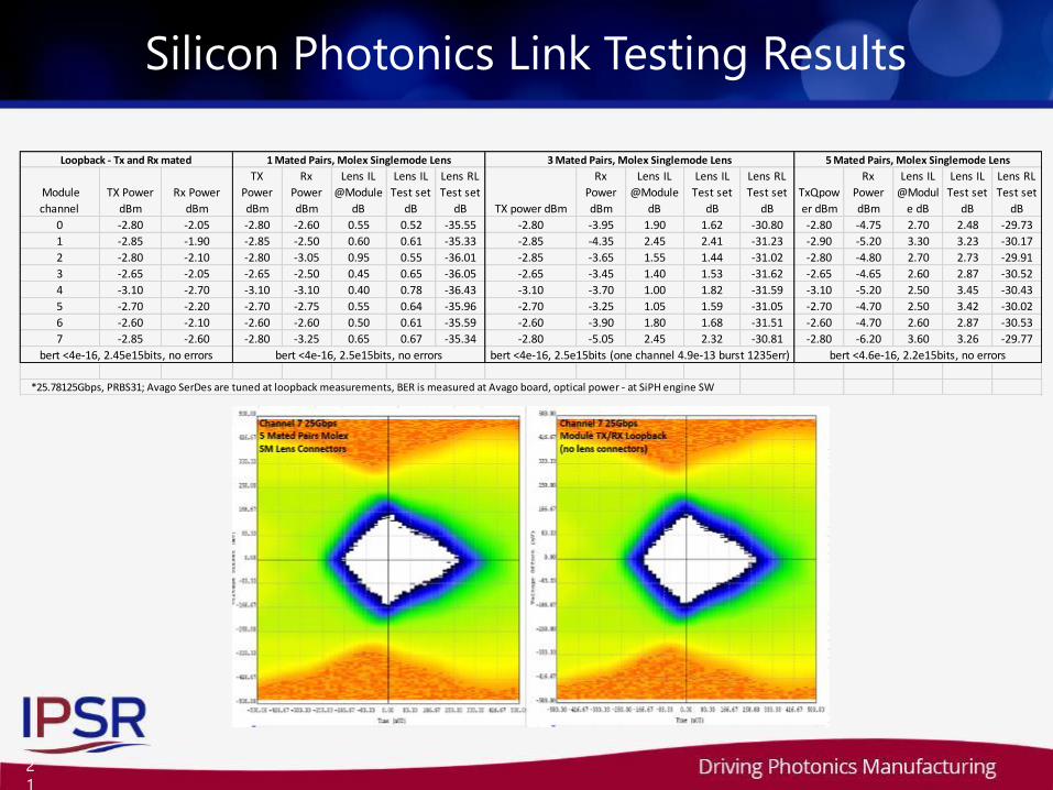
Silicon Photonics Link Testing Results
2
1
Module
channel
TX Power
dBm
Rx Power
dBm
TX
Power
dBm
Rx
Power
dBm
Lens IL
@Module
dB
Lens IL
Test set
dB
Lens RL
Test set
dB TX power dBm
Rx
Power
dBm
Lens IL
@Module
dB
Lens IL
Test set
dB
Lens RL
Test set
dB
TxQpow
er dBm
Rx
Power
dBm
Lens IL
@Modul
e dB
Lens IL
Test set
dB
Lens RL
Test set
dB
0 -2.80 -2.05 -2.80 -2.60 0.55 0.52 -35.55 -2.80 -3.95 1.90 1.62 -30.80 -2.80 -4.75 2.70 2.48 -29.73
1 -2.85 -1.90 -2.85 -2.50 0.60 0.61 -35.33 -2.85 -4.35 2.45 2.41 -31.23 -2.90 -5.20 3.30 3.23 -30.17
2 -2.80 -2.10 -2.80 -3.05 0.95 0.55 -36.01 -2.85 -3.65 1.55 1.44 -31.02 -2.80 -4.80 2.70 2.73 -29.91
3 -2.65 -2.05 -2.65 -2.50 0.45 0.65 -36.05 -2.65 -3.45 1.40 1.53 -31.62 -2.65 -4.65 2.60 2.87 -30.52
4 -3.10 -2.70 -3.10 -3.10 0.40 0.78 -36.43 -3.10 -3.70 1.00 1.82 -31.59 -3.10 -5.20 2.50 3.45 -30.43
5 -2.70 -2.20 -2.70 -2.75 0.55 0.64 -35.96 -2.70 -3.25 1.05 1.59 -31.05 -2.70 -4.70 2.50 3.42 -30.02
6 -2.60 -2.10 -2.60 -2.60 0.50 0.61 -35.59 -2.60 -3.90 1.80 1.68 -31.51 -2.60 -4.70 2.60 2.87 -30.53
7 -2.85 -2.60 -2.80 -3.25 0.65 0.67 -35.34 -2.80 -5.05 2.45 2.32 -30.81 -2.80 -6.20 3.60 3.26 -29.77
*25.78125Gbps, PRBS31; Avago SerDes are tuned at loopback measurements, BER is measured at Avago board, optical power - at SiPH engine SW
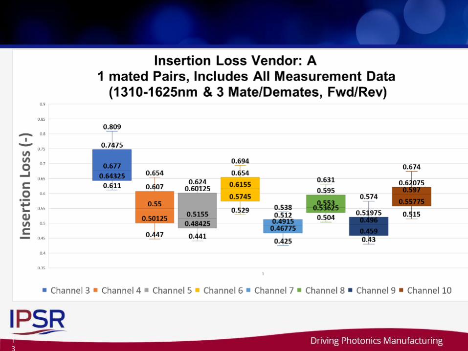
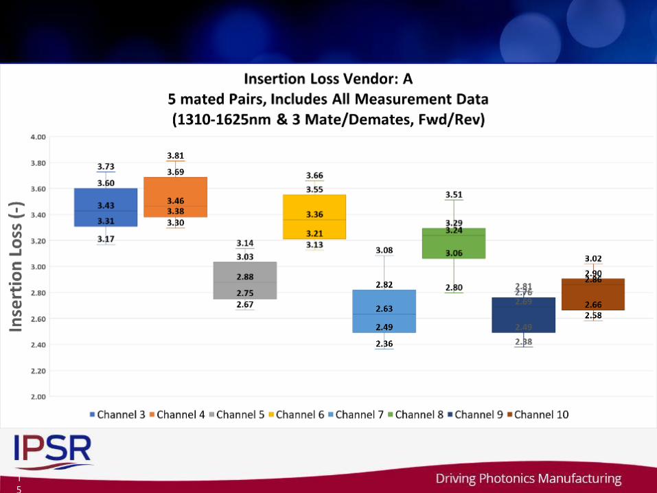
Loopback - Tx and Rx mated 5 Mated Pairs, Molex Singlemode Lens3 Mated Pairs, Molex Singlemode Lens1 Mated Pairs, Molex Singlemode Lens
bert <4.6e-16, 2.2e15bits, no errorsbert <4e-16, 2.5e15bits (one channel 4.9e-13 burst 1235err)bert <4e-16, 2.5e15bits, no errorsbert <4e-16, 2.45e15bits, no errors

Detail Schedule
2
2
CompletedPendingDropped
Deliverables
• Quantification of the performance achievable with
singlemode expanded beam MT ferrules and silicon-
photonics on-board interconnect
• Understanding of system tradeoffs in designing a silicon-
photonics based on-board interconnect system
• Identification of component developments needed to fill gaps
in the ecosystem of silicon-photonics-based on-board
interconnect
• Build confidence for acceleration of the markets for
associated silicon photonics transceivers, connector
components, and fiber cables
23
Summary
• Prototype singlemode multifiber expanded beam connectors
manufactured by multiple vendors utilizing differing
technologies and approaches were tested for performance in
front panel and blind mating optical backplane connector
configurations
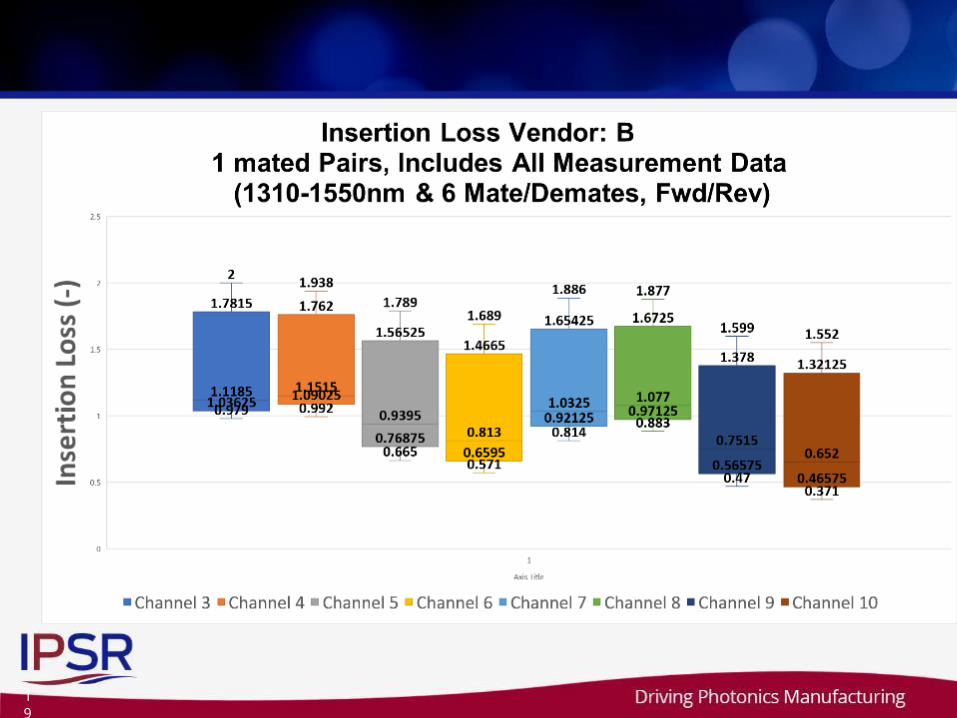
• Concatenated links of one to five mated pairs of connectors
showed stable measurements with repeated mating and no
detrimental effects on parallel 25Gb/s silicon photonic device
links running PRBS32 data patterns
• Further testing on the effects of temperature, debris
contamination and cleaning methods are recommended for
further learning to build confidence in the technology
24
Next-- IPSR Phase II:Expanded-beam Module Interface Project
• Phase II of the AIM Photonics / iNEMI Board-Level Interconnect
Demonstrator project will consist of specifying, designing,
modeling, building and demonstrating a board-level optical
interconnect system in which an expanded-beam optical connector
interface will be developed for the chip module.
• Given the complexity of the challenge, and the time and cost
associated with fabrication of specialized tooling for optical
coupling parts, the Phase II effort is subdivided into 2 Sub-phases,
IIa and IIb, each lasting approximately one year
Each Sub-phase will be a separate
iNEMI QuickTurn Project
Contact list
• Project Information / Interest in Participation:
– Terry Smith, 3M, [email protected]
– Tom Marrapode, Molex,[email protected]
• iNEMI & IPSR Organizations
– Robert C. Pfahl, - iNEMI, (IPSR) AIM Photonics Academy,
– Grace O’Malley, iNEMI, [email protected]
– David Godlewski, iNEMI, [email protected]
– iNEMI, www.inemi.org
– IPSR, www.photonicsmanufacturing.org
26
iNEMI ProjectProject Update iNEMI Webinar 6/13/2018
Top Related