


Languages
Pages
Legal


Inverter-DrivenInduction Motors
Shaft and BearingCurrent Solutions
INDUSTRY WHITE PAPER

Table of Contents
Executive Summary ............................................................................................................ 3Sine Wave Bearing and Shaft Currents ............................................................................... 5Inverter-Driven Motor Bearing Currents ............................................................................ 6Grounding in Inverter-Driven Motor Systems .................................................................. 10Field Measurement of Inverter-Induced Bearing Currents ............................................... 12Table 1: Bearing Current Measurement Equipment Requirements .................................. 13Bearing Damage from Currents ........................................................................................ 17Bearing Current Remediation for Inverter-Driven Motors ............................................... 19Table 2: Bearing Current Remediation (Motor-Based) ..................................................... 20Improve High Frequency Grounding Connection from the Motor to the Drive and from the Motor to the Load ........................................ 21Insulated Coupling Between the Motor and the Driven Equipment ................................. 21Shaft Grounding Brush without Insulated Bearing........................................................... 22One Insulated Bearing on the Motor ................................................................................ 22Shaft Grounding Brush with One or Two Insulated Motor Bearings ............................... 23Electrostatically Shielded Induction Motor (ESIM) ......................................................... 24Standard Practice for Bearing Protection.......................................................................... 25Field Experiences .............................................................................................................. 26
Systems/Process Line Installation ñMotors Coupled to Gearboxes or other MachineryCase 1 ......................................................................................................................... 26Case 1A....................................................................................................................... 27Case 2 ......................................................................................................................... 28Case 3 ......................................................................................................................... 29HVAC Application ñ Motors Coupled to Fans via Non-conductive BeltsCase 4 ......................................................................................................................... 29
Continuing Areas of Research .......................................................................................... 30Drive Design Issues .......................................................................................................... 32Conclusion ........................................................................................................................ 33Table 3: Bearing Current Remediation For Motor And Coupled Equipment ................... 35References ........................................................................................................................ 37Appendix
Grounding/Bonding .................................................................................................... 38Vibration Analysis of Bearing Damage due to Passage ofCurrent in a PWM Environment ................................................................................. 39Capacitor Current Flow .............................................................................................. 41Rolling Bearing Electrical Behaviors ......................................................................... 44

Executive Summary
The vast majority of bearing failures in electric motors are due to mechanical and thermal
causes. Potential causes of these types of failures include misalignment of the motor and load,
vibration, incorrect lubrication, excessive radial or axial loading, lubricant contamination or
inadequate maintenance. In a small fraction of electric motor applications, bearings prematurely
fail due to electrical causes.
Currents flowing through induction motor bearings have the potential of creating premature
failure of these bearings. Shaft and bearing currents in sine wave driven motors are well
understood. These currents are either localized in the bearing or are driven through the bearing
due to asymmetries in the motor material properties or construction. The low frequency nature
of bearing and shaft currents in sine wave driven motors results in current paths through what
are generally considered to be conductive materials (motor shafts, frames, bearing races and
bearing balls). Interrupting the conducting current path with insulating materials can eliminate
these low frequency shaft and bearing currents.
Electric motors powered by fast switching pulse width modulated (PWM) voltage source
inverters experience high frequency voltage pulses with respect to motor ground. At these high
frequencies (up to several MHz transitions) capacitively coupled currents can flow through
paths that would normally be considered to be insulators. Currents now can flow through the
magnet wire insulation, stator slot liners, motor air gap, bearing grease and stator slot top sticks.
These high frequency current paths offer new opportunities for shaft and bearing current flow
that can result in premature bearing failure. With inverter driven motors, a clear understanding
of high frequency current paths from the motor terminals back to the inverter and to ground is
Inverter-Driven Induction MotorsShaft and Bearing Current Solutions
Inverter-Driven Induction Motors Shaft and Bearing Current Solutions 3

key to determining potential bearing current problems and remedies. Current paths both internal
to the motor and between the inverter, the motor and the driven equipment must all be considered
when looking for methods to reduce unwanted bearing current flow. Consequently system related
issues, such as grounding and cable shielding, become very important to inverter powered electric
motor bearing current remediation.
It should be pointed out that inverter-induced bearing currents have not been found to cause
significant problems in the majority of applications. This report focuses on that small percentage
of installations and applications in which damage as a result of bearing currents is possible.
Topics to be presented include:
1) root causes of inverter induced motor bearing currents,
2) potential current paths of capacitively coupled currents,
3) bearing damage due to these currents,
4) preferred current paths for capacitively coupled currents,
5) examples of application problems and solutions,
6) field measurements of important voltages and currents,
7) remediation methods and
8) on-going research into motor bearing current modeling.
Inverter-Driven Induction Motors Shaft and Bearing Current Solutions 4

Sine Wave BearingAnd Shaft Currents
Electric motor bearing and shaft currents are
not new; in fact, they have been around since
electric motors were invented. The most
common underlying causes of unwanted bearing
and shaft currents for sine wave driven motors
is a lack of motor symmetry. C. U. T. Pearce,
writing as early as 1927 in The Electric Journal,
said of the subject: ìIf it were possible to design
a perfectly balanced and symmetrical machine,
both theory and practice indicate that no bearing
current could exist.î To this point, however,
perfect balance and symmetry have been beyond
the technological capabilities of manufacturing,
especially in large electric motors. Therefore,
methods to reduce the detrimental effects of shaft
/ bearing currents have been developed for sine
wave powered motors. It is important to
understand these low frequency, internally
sourced bearing current issues and accepted
remedies. These remedies must be kept in mind
so that when remedies for the high frequency,
externally sourced, inverter-driven motor bearing
currents are applied, they do not re-introduce a
sine wave bearing current problem. Low
frequency, internally sourced sine wave bearing
current flows exist even with inverter-driven
motors.
The two primary causes of shaft and bearing
currents in sine wave driven motors are 1)
homopolar flux, i.e. flux flowing down the center
of the motor shaft and 2) alternating flux linking
the motor shaft. The second cause is much more
common than the first. Consider the homopolar
flux condition as shown in Figure 1.
The homopolar flux condition describes the
flow of flux down the motor shaft, through the
bearing system, and back through the frame.
Generally seen in high-speed, fast-rotating
machines, this axial shaft flux is created by
unbalanced ampere turns that encircle the shaft,
a broken rotor bar, residual magnetization or,
occasionally, an eccentric air gap. It most
commonly occurs in sleeve bearings. Currents
are usually localized to the bearing so there is
no way to provide measurement. The effects of
homopolar flux induced bearing currents are
generally minor and are remedied by providing
a homopolar flux barrier such as a nonmagnetic
shaft or insulated bearings.
Inverter-Driven Induction Motors Shaft and Bearing Current Solutions 5
Figure 1: Homopolar flux condition creating bearingcurrents.

The more common type of bearing current is
caused by alternating flux linking the motor
shaft, as a result of asymmetrical magnetic
properties of the stator or rotor core. Electric
steel is not totally homogenous therefore flux
paths in the motor are not entirely symmetrical.
Asymmetrical flux through the steel results in
flux lines that enclose the shaft. This can drive
a current down the shaft, to the bearings, through
the frame and back again through the bearings
as shown in Figure 2.
The resulting current is not localized within the
bearing. Its driving voltage can be measured on
motors with at least one bearing that is
electrically insulated from the motor frame. (See
Institute of Electrical and Electronics Engineersí
(IEEE) Standard 112-1996). When both
bearings in the current path are conducting, the
impedance of this path is small; therefore, an
axial shaft voltage as little as 500 millivolts rms
can create a current of up to 20 amps rms through
the bearing and can cause significant bearing
damage, particularly in larger machines.
Remedial action entails employing an electrical
insulator outside the bearing outer race to break
the current path.
Bearing currents in sine wave driven motors
can be reduced or eliminated through current or
flux barriers. This is because the bearing currents
are internally sourced. Notice that these types
of bearing currents are not dependent upon
system installation issues, such as grounding.
Inverter-Driven Motor BearingCurrents
With PWM inverter-driven motors, both
internally and externally sourced bearing
currents may exist. The internally sourced
currents are the same as those discussed for sine
wave motors above. The externally sourced
currents are a result of the voltage wave shape
that is applied to the motor by the inverter.
Modern PWM inverters switch a DC bus
voltage (Vdc) onto the three phase terminals of
the motor in a switching pattern that creates the
proper fundamental component voltage and
frequency. Since the motor line to line terminal
voltage must be either + Vdc or ñ Vdc, it is not
possible to have the three terminal voltages add
to zero at any instant of time. Most rectifiers that
create the DC bus also introduce a common mode
Inverter-Driven Induction Motors Shaft and Bearing Current Solutions 6
Figure 2: Alternating flux linking the shaft.
voltage to the DC bus itself. The average voltage
applied to the motor (over a cycle) is kept zero,
but the instantaneous sum of the voltages at the
motor terminals is nonzero. This instantaneous
voltage sum is called the common mode voltage.
It can be measured by creating an artificial Y
connection at the motor terminals using three
large resistors (Mega ohms). The voltage from
the center of this Y to the motor ground is the
common mode voltage.
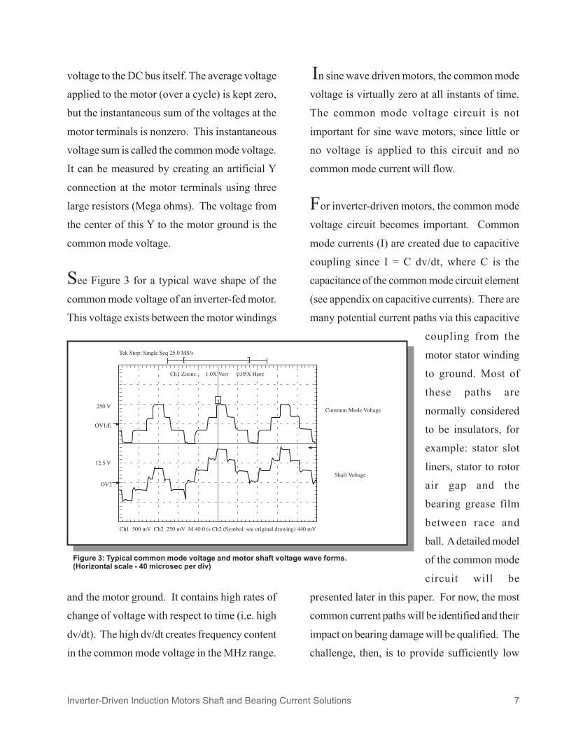
See Figure 3 for a typical wave shape of the
common mode voltage of an inverter-fed motor.
This voltage exists between the motor windings
and the motor ground. It contains high rates of
change of voltage with respect to time (i.e. high
dv/dt). The high dv/dt creates frequency content
in the common mode voltage in the MHz range.
In sine wave driven motors, the common mode
voltage is virtually zero at all instants of time.
The common mode voltage circuit is not
important for sine wave motors, since little or
no voltage is applied to this circuit and no
common mode current will flow.
For inverter-driven motors, the common mode
voltage circuit becomes important. Common
mode currents (I) are created due to capacitive
coupling since I = C dv/dt, where C is the
capacitance of the common mode circuit element
(see appendix on capacitive currents). There are
many potential current paths via this capacitive
coupling from the
motor stator winding
to ground. Most of
these paths are
normally considered
to be insulators, for
example: stator slot
liners, stator to rotor
air gap and the
bearing grease film
between race and
ball. A detailed model
of the common mode
circuit will be
presented later in this paper. For now, the most
common current paths will be identified and their
impact on bearing damage will be qualified. The
challenge, then, is to provide sufficiently low
Inverter-Driven Induction Motors Shaft and Bearing Current Solutions 7
Figure 3: Typical common mode voltage and motor shaft voltage wave forms.(Horizontal scale - 40 microsec per div)

impedance ground connections or alternate
conductive paths to ensure that the flow of
current is properly channeled away from the
bearing.
In Figure 4, the various current paths of
capacitively coupled current are presented. The
high dv/dt created in the stator winding couples
capacitively with the stator core and frame and
with the rotor. The relative magnitude of the
currents flowing in these paths is strongly
dependent upon the impedance of these paths.
As will be shown later, bearing damage can be
reduced or eliminated by creating low impedance
current paths that route these currents away from
the bearings. Letís first take a look at each
current path shown.
The current path marked in red (óóó-) is a
capacitive current coupled to the rotor, with a
return path to the motor bearings, motor ground
connection and finally to the drive ground. This
path creates current through the motor bearing
with possible bearing damage as a consequence.
Current flow through the bearing is a
consequence of two phenomena. Conduction
current may flow
through the motor
bearing if the shaft
happens to be
shorted to the
frame (by bearing
ball contact, for
example) at the
instant that the dv/
dt transition occurs
in the common
mode voltage. Dis-charge current may flow
through the motor bearings if the bearing
becomes conductive after first acting as an
insulator. Discharge current may occur when
the voltage across the bearing lubricant film
exceeds the film breakdown voltage. The red
current may not be directly measured without a
specially instrumented motor since the entire
current path is inside the motor.
The path marked in green (óóó-) shows
current that is again capacitively coupled from
the stator winding to the rotor. The coupling
could be through the same mechanism as the red
current path, but this green current component
finds a preferred path that passes through a
Inverter-Driven Induction Motors Shaft and Bearing Current Solutions 8
Figure 4: Current paths of capacitively coupled currents.

conductive coupling, and through at least one
load bearing, to the load ground and back to the
drive ground. The same two phenomenon
discussed for the red current can occur with the
green current, only now the conductive or
insulating state of the load bearing will determine
the type of current flow. This path creates current
through the load
bearing and the
motor to load
coupling with the
potential of
creating damage in
the load bearing or,
for some types of
couplings, the
coupling itself.
This current can be measured by putting a high
frequency current sensor around the motor shaft.
(See Table 1).
The gold path in Figure 4 (óóó-) indicates
capacitively coupled current between the stator
winding and the frame. This current flows
through the stator winding insulation (which is
capacitively conductive at high frequencies).
With a poor motor to drive high frequency
ground connection, the gold current flows
through the motor frame, the motor bearing, the
motor shaft, the conductive coupling, the load
bearing, the load ground and finally to the drive
ground. Current through this path has the
potential to damage the motor and load bearings,
as well as the motor to load coupling. This gold
path would also include currents due to a
transient voltage difference between the motor
frame and the driven equipment.
The preferred path for all these currents, to
reduce bearing damage, is the blue path (óóó-) in Figure 4. Here, no current flows through
the motor or load bearings.
The current paths shown in Figure 4 are shown
as lumped circuit currents. In fact, the
capacitively coupled current flow is distributed
along the stator winding. This implies that
current ìleaksî from the winding over the length
of the winding, so that the axially directed current
at the winding input is more than at the winding
exit point. The result of this phenomenon is
shown in Figure 5, where a net axial current is
shown flowing in the motor stator winding.
Inverter-Driven Induction Motors Shaft and Bearing Current Solutions 9
Figure 5: High frequency flux encircling the rotor causing shaft and bearing current.
There is also a simultaneous drawing of current
to the stator core and stator frame that represents
the current that has bled from the stator winding
due to capacitive coupling. The combination of
these events creates an encirculating flux and a
high frequency current flow down the shaft,
through the bearings and the motor frame. This
current may have the potential to damage the
motor bearings. This type of current is neither
well understood nor easy to measure. It can be
reduced by placing an insulator (that must be
sufficiently high impedance to high frequencies
as well) in the current path and is usually
accomplished by insulating one motor bearing
from the motor frame.
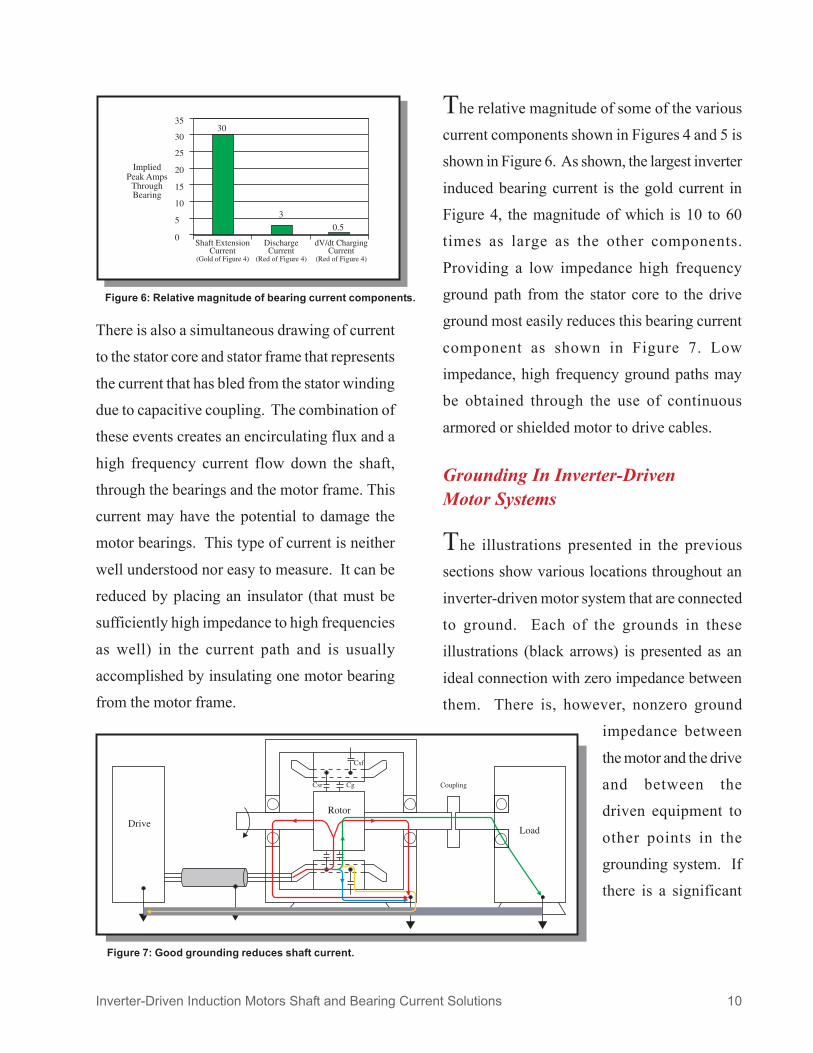
The relative magnitude of some of the various
current components shown in Figures 4 and 5 is
shown in Figure 6. As shown, the largest inverter
induced bearing current is the gold current in
Figure 4, the magnitude of which is 10 to 60
times as large as the other components.
Providing a low impedance high frequency
ground path from the stator core to the drive
ground most easily reduces this bearing current
component as shown in Figure 7. Low
impedance, high frequency ground paths may
be obtained through the use of continuous
armored or shielded motor to drive cables.
Grounding In Inverter-DrivenMotor Systems
The illustrations presented in the previous
sections show various locations throughout an
inverter-driven motor system that are connected
to ground. Each of the grounds in these
illustrations (black arrows) is presented as an
ideal connection with zero impedance between
them. There is, however, nonzero ground
impedance between
the motor and the drive
and between the
driven equipment to
other points in the
grounding system. If
there is a significant
Inverter-Driven Induction Motors Shaft and Bearing Current Solutions 10
Figure 6: Relative magnitude of bearing current components.
Figure 7: Good grounding reduces shaft current.
pulse of high frequency current, all various paths
available will be used, and the current will split
in inverse proportion to the impedance offered
by the respective paths. With equal impedance
ñ for a desired path from the motor back to the
drive and for the undesired one through the
bearings to the driven equipment ñ the situation
arises in which half the current might be carried
by each path, creating an undesirable situation.
The current generated by the common mode
voltage (the I in the I = C dv/dt equation) is the
common mode current. It is important to provide
low impedance grounding paths for the common
mode current to keep current from flowing
through the bearings.
One important ground current path connection
is between the motor and the inverter. The
magnitude of the motor frame voltage, as well
as the common mode current, is influenced by
the type of ground and shield connection of the
inverter to motor cabling system. Cables that
provide continuous, low resistivity shielding
around the three phase conductors provide the
lowest motor common mode current and motor
frame voltage. Continuous corrugated aluminum
sheathed cables provide this optimum
performance and are highly recommended for
motor/inverter installations. The continuous
aluminum sheath provides low resistance and
low inductance, an important feature that results
in minimum high frequency impedance.
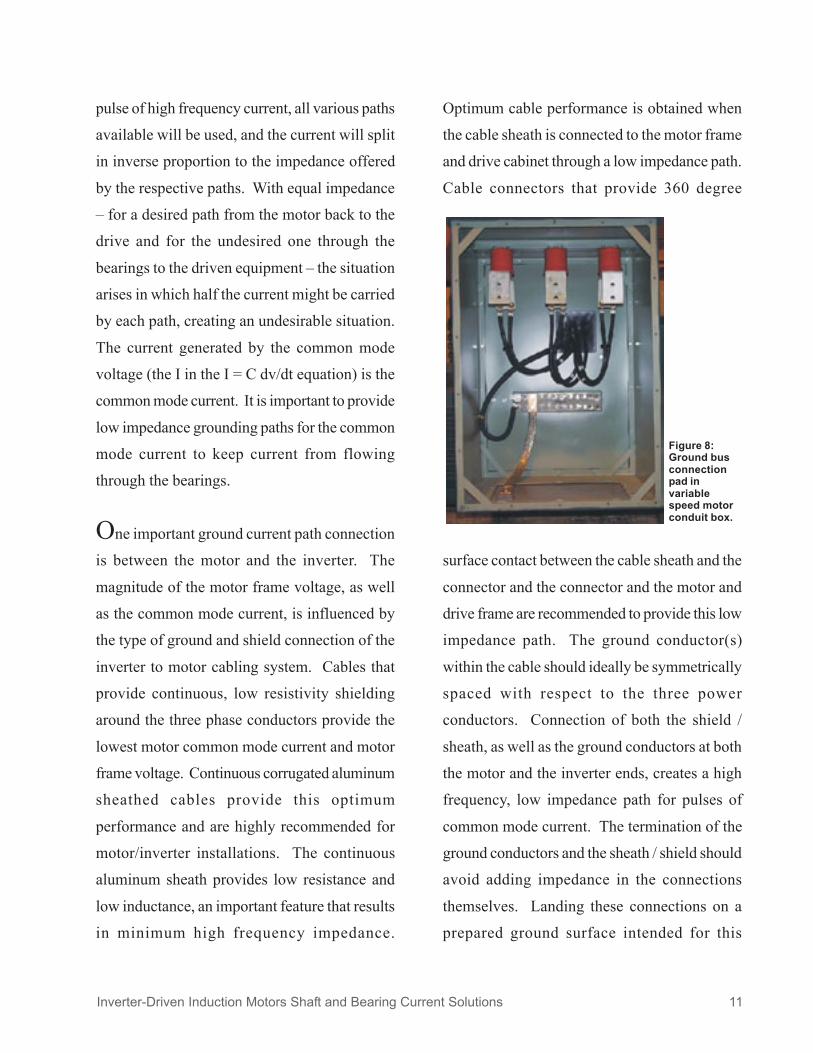
Optimum cable performance is obtained when
the cable sheath is connected to the motor frame
and drive cabinet through a low impedance path.
Cable connectors that provide 360 degree
surface contact between the cable sheath and the
connector and the connector and the motor and
drive frame are recommended to provide this low
impedance path. The ground conductor(s)
within the cable should ideally be symmetrically
spaced with respect to the three power
conductors. Connection of both the shield /
sheath, as well as the ground conductors at both
the motor and the inverter ends, creates a high
frequency, low impedance path for pulses of
common mode current. The termination of the
ground conductors and the sheath / shield should
avoid adding impedance in the connections
themselves. Landing these connections on a
prepared ground surface intended for this
Figure 8:Ground busconnectionpad invariablespeed motorconduit box.
Inverter-Driven Induction Motors Shaft and Bearing Current Solutions 11
purpose is a good way to accomplish this. Motor
conduit boxes can be provided with a multipoint
ìground busî connection pad, as seen in
Figure 8.
Proper grounding of the motor frame is also
important. Capacitively coupled currents from
the stator winding to the motor frame are the
largest potential component of bearing current
in applications with conductive shaft couplings
(shaft extension current in Figure 6). Besides
the cableís low impedance ground path from the
motor to the inverter, ground straps should also
be connected between the motor frame and the
driven load equipment frame to allow a low
impedance, alternate path for shaft currents. This
is particularly important in applications where a
conductive coupling connects the motor shaft to
the driven equipment and where the motor and
driven equipment are NOT on a common metal
baseplate. High frequency ground strap
impedance is lowest for straps with fine
conductors and the largest width to length ratio.
Therefore, the widest ground strap that is
practical should be used for this ground
connection. In all cases, ground straps should
be connected directly metal to metal (not through
a painted surface) to provide the lowest
impedance path for high frequency currents.
Field Measurement Of Inverter-Induced Bearing Currents
Measuring bearing voltages and currents
presents significant challenges. As stated earlier,
it is difficult to accurately measure current flow
through the bearing. This difficulty arises
because it is not possible to place a current
transducer in the part of the bearing where the
current actually flows. Therefore, field
measurements are largely relegated to methods
that will provide insight into symptoms of
potential bearing current problems. Many field
measurements are done after bearing damage has
occurred, where causes are being determined so
that the proper remediation action can be taken.
Since the source of the high frequency bearing
currents is the common mode voltage transitions
from the inverter, it is important to reference all
system measurements to the common mode
voltage wave form. Shaft to ground voltage
measurement (both magnitude and wave shape)
provides insight into potential bearing current
flows. Although bearing currents cannot be
directly measured, current flow through various
grounding and ground current return paths can
and should be measured, including current
flowing through the motor drive shaft to the load.
Typical field measurement goals include:
1) determine common mode voltage level
and wave shape,
2) compare shaft to frame voltage
Inverter-Driven Induction Motors Shaft and Bearing Current Solutions 12
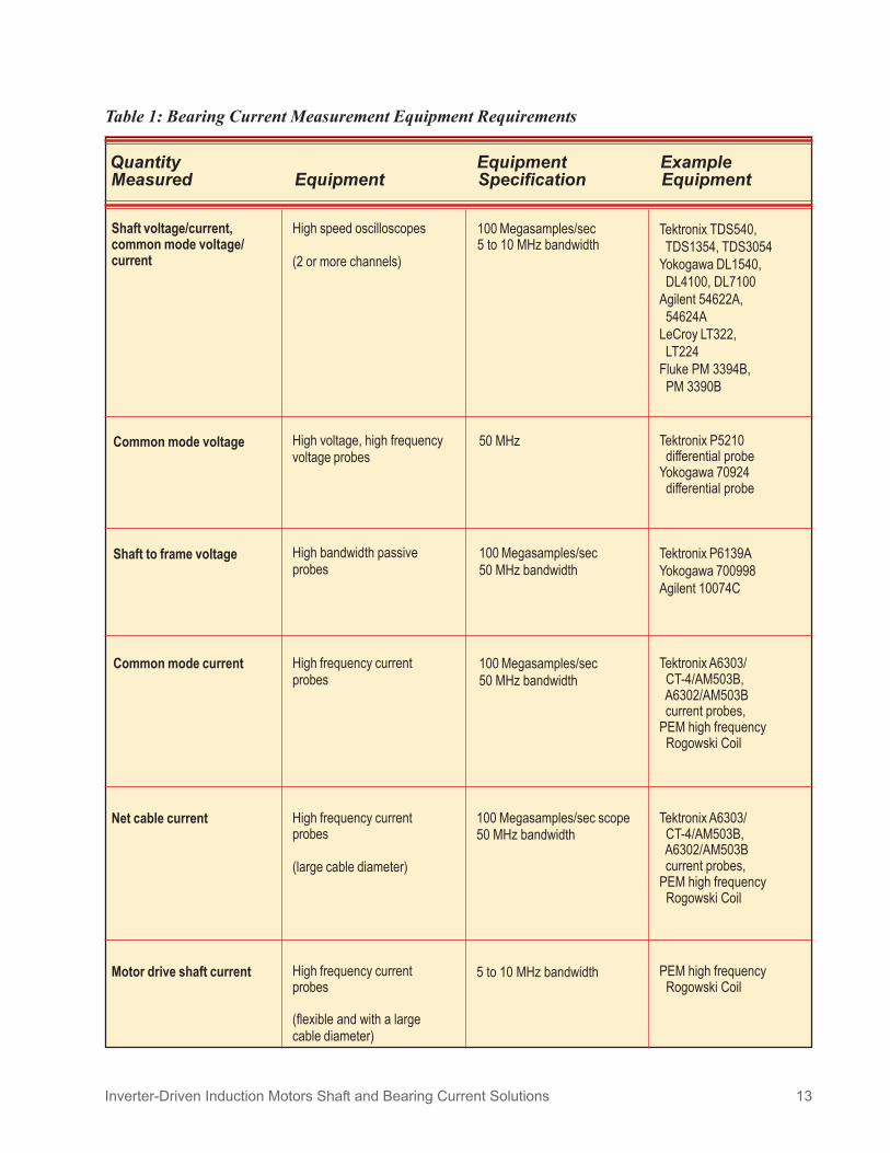
Table 1: Bearing Current Measurement Equipment Requirements
Quantity Equipment ExampleMeasured Equipment Specification Equipment
High speed oscilloscopes
(2 or more channels)
100 Megasamples/sec5 to 10 MHz bandwidth
Common mode voltage High voltage, high frequencyvoltage probes
50 MHz
Shaft voltage/current,common mode voltage/current
Tektronix TDS540, TDS1354, TDS3054Yokogawa DL1540, DL4100, DL7100Agilent 54622A, 54624ALeCroy LT322, LT224Fluke PM 3394B, PM 3390B
Tektronix P5210 differential probeYokogawa 70924 differential probe
Shaft to frame voltage High bandwidth passiveprobes
100 Megasamples/sec50 MHz bandwidth
Tektronix P6139AYokogawa 700998Agilent 10074C
Common mode current High frequency currentprobes
100 Megasamples/sec50 MHz bandwidth
Tektronix A6303/ CT-4/AM503B, A6302/AM503B current probes,PEM high frequency Rogowski Coil
Net cable current High frequency currentprobes
(large cable diameter)
100 Megasamples/sec scope50 MHz bandwidth
Tektronix A6303/ CT-4/AM503B, A6302/AM503B current probes,PEM high frequency Rogowski Coil
Motor drive shaft current High frequency currentprobes
(flexible and with a largecable diameter)
5 to 10 MHz bandwidth PEM high frequency Rogowski Coil
Inverter-Driven Induction Motors Shaft and Bearing Current Solutions 13

magnitude and wave shape with common
mode voltage wave shape to deduce bearing
current activity, and
3) determine common mode current flow
both in preferred current paths and alternate
ground current paths.
To reach these goals, equipment capable of
measuring high frequency events is required.
Table 1 lists required capability of measurement
equipment for various field measurements.
Common mode voltage measurement is usually
done by creating an artificial neutral for the three
phase voltages applied to the motor terminal.
Three high-value low inductance type symmetric
resistors are connected in Y. One end of each
resistor is connected to the three phase leads.
The measurement is taken from the center point
of this resistor Y to the motor ground. The
common mode voltage is to be used as a
reference for shaft voltage
and common mode current
measurements, so it is
usually displayed on one of
the scope channels for all
further measurements on the
motor system. The rise time
and overshoot of the
common mode voltage
provides insight into the
level of dv/dt and peak
common mode voltage of
this motor/inverter system. Figure 9 (top trace)
contains a typical common mode voltage wave
shape.
Motor shaft to frame voltage measurements
should be made with a brush or pick up that can
make contact with the shaft while in motion. The
shaft voltage is measured relative to a ground
reference point. The ground point should be a
non-painted, and preferably external, motor
ground connection point as close as possible to
the bearing outer race. A high frequency
oscilloscope is required, often combined with a
high voltage, high frequency probe (see Table
1). Among the challenges in measuring shaft to
frame voltage is that the bearings exhibit a
significantly stochastic behavior. Bearings
change from insulating mode to conducting
mode in a somewhat random fashion and in
response to applied voltage. Factors such as the
Inverter-Driven Induction Motors Shaft and Bearing Current Solutions 14
Figure 9: Typical common mode voltage and motor shaft voltage wave forms.

state of the bearing grease (temperature,
contaminant level, churning), rotation speed and
the applied voltage level impact the voltage wave
shapes. Additionally, the PWM transitions are
not all identical. If the turn on time of a transistor
is nominally 50 nanoseconds (ns), the actual turn
on time might be 50 ns in one instance and 150
ns in another. Since each transition is different,
the scope should be DC triggered and with the
trigger level set to display the highest voltage
excursions in order to measure the maximum
voltage across the bearing.
The shaft to frame voltage may exhibit one of
several possible phenomena. If current through
the bearing due to common mode voltage is
infrequent, the shaft to frame voltage wave shape
will mimic the common mode voltage wave
Inverter-Driven Induction Motors Shaft and Bearing Current Solutions 15
shape (but with reduced
amplitude) for most time
ranges. In this case, there
may be sudden
occurrences of zero shaft
to frame voltage after a
voltage charge-up (see
Figure 9), which implies
a bearing conducting
mode and a pulse of
bearing current. The
current that flows during
this conducting period
can damage the bearing.
An illustration of this phenomenon is shown in
Figure 10, which shows measurements taken on
a special lab motor constructed with an insulating
ring between the bearing outer race and the motor
frame and with a single wire shorting across that
ring. The current flow through this wire is
indicative of the bearing current. As shown, just
before t=150 µsec, the shaft to frame voltage is
zero, due to a previous bearing shorting and
reopening. At t = 150 µsec, the shaft to frame
voltage is following the common mode voltage
transitions until just before t=250 µsec. At t=250
µsec the shaft voltage drops to zero and a 3 amp
current pulse appears in the bearing.
The instant the current pulse occurs, the trapped
charge on the rotor discharges through the
bearing balls and race. One method for this to
Figure 10: Bearing current due to rotor voltage discharge.(Stator Neutral Voltage = Common Mode Voltage)

occur is random direct contact of the balls to the
race, which can result in the shorting out of the
bearing. This is most likely to happen at low
speed, but not exclusively so. A second method
is current shoot-through of the bearing
lubrication film, which generally happens at high
speed where the balls are separated from the race
by a lubricant. Discharges through the bearing
may also be some combination of these two
methods. In any case, a conducting path is
created that may be small in area so that a high
current density can be created.
In some cases, the shaft to frame voltage wave
shape will show instances of mostly zero voltage
with attempts to charge up. This implies that
the bearing may be staying in a conducting mode
so that the rotor does not build up a substantial
voltage.
Common mode current measurements are made
to determine if current flow is occurring in
undesirable paths. Undesired paths include
through the motor bearing and the motor shaft
extension into driven equipment. Common mode
current into the motor is the instantaneous sum
of the three phase currents going into the motor.
Common mode current flows into the motor from
the inverter and eventually returns back to the
inverter. The preferred return path (as mentioned
above) is through a low impedance ground
conductor from the motor to the inverter. The
common mode current into the motor can be
measured by placing a current transducer around
the three motor power leads (without ground
leads, shields, etc.). By comparing this
measurement to the current through the ground
conductors (including the conductor shields),
stray common mode current can be determined.
If the ground conductors are the
preferred ground paths, they should
carry all of the common mode current.
Figure 11 shows measured common
mode current into a motor. Common
mode current pulses occur at each
transition of the common mode
voltage (the dv/dt capacitively coupled
effects). A difference between the
ground conductor current and the
common mode input current can lead
to a diagnosis of a grounding system
problem. Another technique to
Inverter-Driven Induction Motors Shaft and Bearing Current Solutions 16
Figure 11: Measured common mode current wave.
determine if currents are flowing in undesirable
paths is to measure the net cable current. Here a
high frequency current transducer is placed
around the entire motor incoming cable,
including the ground and shield connections.
Any current spikes measured are an indication
of poor grounding or poor cable connections or
the existence of low impedance paths for the
common mode current through the coupled
equipment.
Current down the output shaft of the motor is
also important to measure. This can be done
using a Rogowski Coil, high frequency response
current transducer (see Table 1). Any measured
current indicates bearing current flow either in
the motor bearing or the driven equipment
bearing or both.
Voltage and current measurements, as described
above, provide an indirect indication of the
potential of bearing current problems. With
experience, these measurements can lead to
proper diagnosis of causes of bearing current
damage in a given installation. There is no
known set of measurements, however, that can
lead to a definitive prediction of future bearing
current damage. There is no established
threshold of shaft to frame voltage above which
bearing damage can be assured and below which
no damage is expected. In fact, a low shaft to
frame voltage may indicate continuous
conduction of the bearing which may lead to
bearing damage. On the other hand, a high shaft
to frame voltage without evidence of discharge
may not result in bearing damage since little or
no current will be flowing in the bearing. This
is one of the challenges of dealing with inverter
driven motor bearing current problems.
Proper interpretation of the measurements can
be realized by being aware of the measurement
challenges which include:••••• Bearing electrical behavior is random in
time and shows nonlinear and hystereticbehavior with temperature, bearingspeed and shaft to frame voltage.
••••• All important voltage and current data isat high frequency.
••••• Key information does not occur at eachPWM transition. Single triggering withappropriate choice of trigger levels willresult in the most useful information.
••••• Sine wave bearing voltage and currentstandards for potential damage cannot bedirectly applied to the prediction ofinverter sourced bearing damage.
••••• Bearing current must always be implied(unless in special laboratory setups) sincecurrent through the bearing is impossibleto measure directly.
Bearing Damage From Currents
We have seen that there are several methods
for bearing currents to flow in inverter-driven
Inverter-Driven Induction Motors Shaft and Bearing Current Solutions 17
motors. Current flow in the bearing can lead to
premature bearing failure.
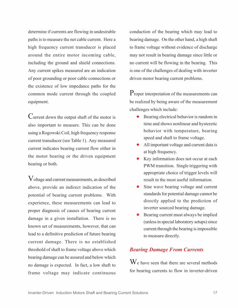
Initial damage is, in fact, relatively minor (see
Figure 12). Bearing damage begins with the
formation of small pits or fusion craters in the
bearing races. As this progresses, mechanical
defects arise that make the damage more the
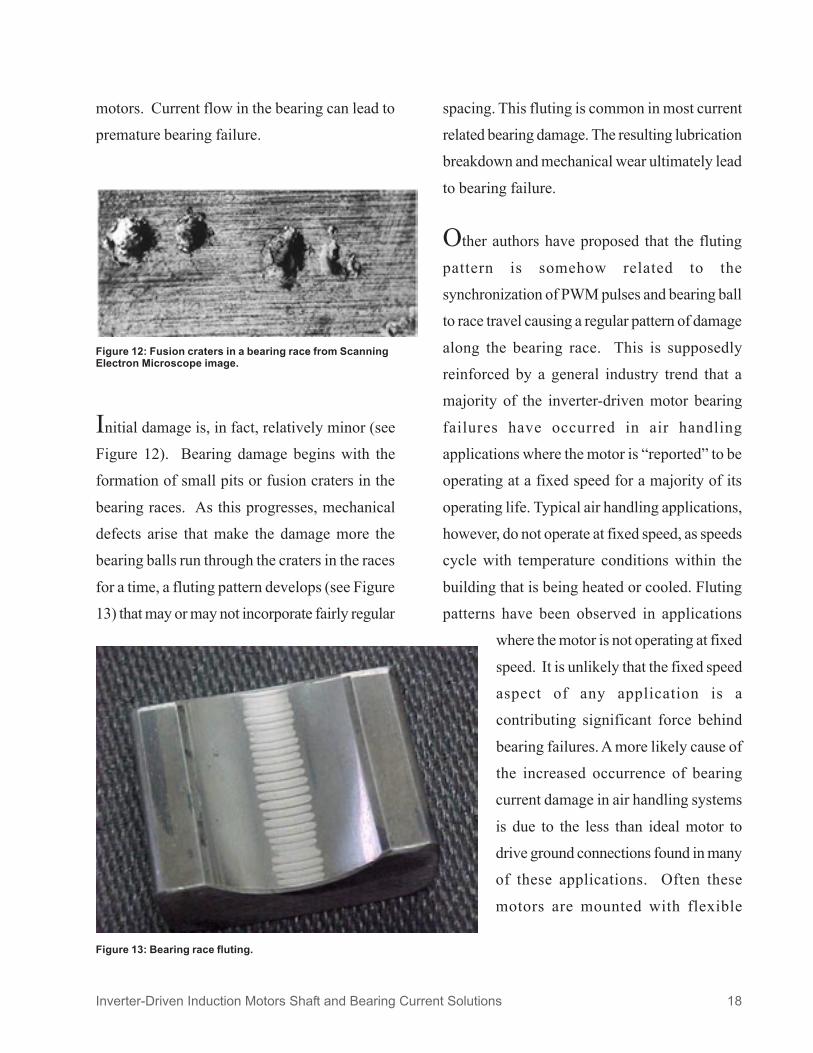
bearing balls run through the craters in the races
for a time, a fluting pattern develops (see Figure
13) that may or may not incorporate fairly regular
spacing. This fluting is common in most current
related bearing damage. The resulting lubrication
breakdown and mechanical wear ultimately lead
to bearing failure.
Other authors have proposed that the fluting
pattern is somehow related to the
synchronization of PWM pulses and bearing ball
to race travel causing a regular pattern of damage
along the bearing race. This is supposedly
reinforced by a general industry trend that a
majority of the inverter-driven motor bearing
failures have occurred in air handling
applications where the motor is ìreportedî to be
operating at a fixed speed for a majority of its
operating life. Typical air handling applications,
however, do not operate at fixed speed, as speeds
cycle with temperature conditions within the
building that is being heated or cooled. Fluting
patterns have been observed in applications
where the motor is not operating at fixed
speed. It is unlikely that the fixed speed
aspect of any application is a
contributing significant force behind
bearing failures. A more likely cause of
the increased occurrence of bearing
current damage in air handling systems
is due to the less than ideal motor to
drive ground connections found in many
of these applications. Often these
motors are mounted with flexible
Figure 13: Bearing race fluting.
Inverter-Driven Induction Motors Shaft and Bearing Current Solutions 18
Figure 12: Fusion craters in a bearing race from ScanningElectron Microscope image.

conduit as the ground return path from motor to
drive, which is not a good high frequency, low
impedance ground. This leads to higher
intermittent bearing voltages that can cause
increased bearing damage.
Bearing Current Remediation ForInverter-Driven Motors
Figures 4 and 5 earlier in this document
schematically showed bearing current paths that
exist in inverter driven electric motors. A number
of solutions are available to reduce or eliminate
these current flows, the appropriateness of each
depending upon the type and source of the
bearing current found. Eliminating or reducing
the common mode voltage and current addresses
the problem at its source. This, however, is a
drive design issue and therefore cannot be easily
addressed in existing applications. Drive designs
that reduce or eliminate common mode voltage
and common mode current flow will be
discussed at the end of this paper. In all cases, a
drive with reduced common mode voltage is
more costly to manufacture than typical PWM
voltage source inverters that are widely marketed
today. Since elimination of the source of the
high frequency bearing currents is not likely due
to this increased drive cost, improvements in the
system grounding and/or modifications of the
motor are often the preferred method to reduce
the potential for bearing current damage.
Table 2 provides a summary of bearing current
remediation methods for each bearing current
flow path. If multiple current paths are expected
in a given application, multiple remediation
methods may be required to eliminate potential
bearing damaging current flow. Methods that
are available are:
1. Improve high frequency grounding
connection from the motor to the drive.
2. Improve high frequency grounding
connection from the motor to the driven
equipment.
3. Insulated coupling between the motor
and the driven equipment.
4. Shaft grounding brush without any
insulated bearings.
5. One insulated bearing on the motor. Two
insulated bearings on the motor.
6. Electrostatically shielded induction
motor (ESIM).
Each of these options will be reviewed to identify
current flow paths and their elimination.
Improve High Frequency GroundingConnection From The Motor To TheDrive And From The Motor To TheLoad
The largest potential component of inverter
induced bearing current is the common mode
current that flows from the stator winding to the
stator core and through the bearing to the load
Inverter-Driven Induction Motors Shaft and Bearing Current Solutions 19

Inverter-Driven Induction Motors Shaft and Bearing Current Solutions 20
Table 2: Bearing Current Remediation (motor-based)
Souce of Current Action Comments
Internal, circulating, due tomagnetic dissymmetry leadingto net flux linking shaft(fundamental frequency or sinewave)
Motor design optimized forsymmetry
Insulate one bearing
Design electromagnetics to achieve maximum symmetry andminimize net flux linking the shaft.
Insulating just one bearing interrupts flow. Since coupledequipment can also provide a path from shaft to ground,usually choose opposite drive end bearing to insulate. Needto avoid ìdefeatingî the bearing insulation, so (a) no groundbrush at same end as a single insulated bearing, and (b)insulated coupling/mounting of accessories (e.g. encoder) atthe end with a single insulated bearing.
Common mode (ground)current (induced by commonmode dv/dt) taking a returnpath via the motor shaftextension and coupledequipment
Insulate both bearings
Insulate coupling
Bonding strap betweenframes
Well terminated cable groundconnections
Bearing insulation has to be of sufficient thickness to presenta high impedance to this high frequency current.Coupling insulation must provide a high impedance at highfrequencies.By bonding the motor frame and the coupled equipmenttogether, a path is provided that should be much lowerimpedance than that through the shaft and bearings. To thisend, the bonding must be a low impedance strap wellterminated at each end.By providing the lowest impedance path back to the source,the tendency for any current to take a path through the shaft /bearings/coupled equipment is minimized.
Discharge through bearing ofcapacitively coupled commonmode voltage (scaled bycapacitor divider)
Motor design to reducevoltage ratioFaraday shield
By controlling the internal design of the motor, the ratio of theshaft voltage to common mode voltage can be minimized.By interposing a grounded conductor between the statorwinding and the rotor, the capacitive coupling can be ìshortedto ground,î reducing the bearing voltage to prevent damage.Since a bearing goes from a non-conducting to a conductingmode in a very short time, this presents a high frequencyevent ó so the insulation needs to be a significantimpedance at high frequencies.This can be effective, but presents maintenance issues.
Capacitively coupled commonmode voltage causingdischarge through orconduction through loadbearings
Insulate coupling
Shaft ground brush
Faraday shield
Coupling insulation must provide a high impedance to highfrequencies. Preferred path may now be through motorbearings.This can be effective, but presents maintenance issues.By interposing a grounded conductor between the statorwinding and the rotor, the capacitive coupling can be ìshortedto ground,î reducing the bearing voltage to prevent damage.
Insulate both bearings
Shaft ground brush

(the gold current in Figure 14). Providing a low
impedance path from the motor ground to the
inverter and from the motor to the load (if there
is a conductive coupling between the motor and
the driven equipment) most easily reduces this
current. Figure 7 previously showed the current
flow when this improved ground path is
provided. High frequency impedance of cable
shielding and ground strapping options
were discussed in an earlier section of
this paper. The desired result is to carry
the ground current back from the motor
to the inverter, as well as to prevent
transient differential voltages from the
motor to the coupled equipment. The
best method of creating the lowest
impedance path between the motor and
the inverter is by focusing on cabling in order to
generate a ground current path closely coupled
with the power leads that supply high frequency
currents. Good termination of the cabling at both
the motor and the inverter assists in the
establishment of a low impedance path.
Insulated Coupling Between TheMotor And The Driven Equipment
Inverter induced currents have the
potential of flowing down the motor
drive shaft to the load causing load
bearing and/or coupling damage.
There are two components of
current that can make up the shaft
extension current of this type (see
Figure 4), one due to capacitive coupling across
the air gap (green) and the other due to common
mode current from the stator core to the load
(gold). Current flow to the load bearings can be
eliminated through the use of an insulated
coupling (see Figure 15). Notice that by
Inverter-Driven Induction Motors Shaft and Bearing Current Solutions 21
eliminating the current flow path to the load
bearing, that there may be an increase in current
flow through the motor bearings, which now
become the only path for all current that is
coupled across the air gap.
Figure 14: Common mode shaft current.
Figure 15: Insulated coupling eliminates shaft current.

One Insulated Bearing On The Motor
Motor bearings can be insulated to break the
high-frequency current paths from the shaft to
ground. For inverter induced bearing currents,
usually an insulated bearing is combined with
an opposite end shaft grounding brush. It is
wrong to add a shaft brush at the same end of
the motor where a single insulated bearing has
been applied, as this could facilitate
internally sourced (sine wave type)
current flow in the uninsulated bearing
at the opposite end. A single insulated
bearing will not prevent shaft to ground
current flow in the uninsulated bearing
at the other end of the motor. A single
insulated bearing, however, is effective
in preventing circulating currents from
flowing, either from sine wave excitation or from
high frequency flux induced bearing currents
(see Figure 5). Figure 17 shows the effect of asingle insulated bearing in eliminating thecirculating current flow of this type of bearingcurrent.
Inverter-Driven Induction Motors Shaft and Bearing Current Solutions 22
Shaft Grounding Brush WithoutInsulated Bearing
A shaft grounding brush can be added to a
motor bearing to provide a preferred path for
bearing currents around the bearing. If the brush
impedance is low enough, all shaft to ground
currents will flow through this brush and will
avoid an alternate path through the motor bearing
without the brush. Figure 16 shows the currentflow paths with a brush on one bearing. Noticethat, without good high frequencyground connections in the system, thebrush has the potential to increasecurrent flow down the shaft byproviding a better current path thanthrough the bearing itself. Adding abrush to a motor also reduces theimpedance seen by any circulatingcurrents within the motor that may besine wave induced (see Figure 2). Sincesine wave bearing currents are most common inlarger motors, it is not recommended to add ashaft brush to a motor above a 400 frame sizethat does not have insulated bearings.
Figure 16: Shaft grounding brush on drive end bearing.
Figure 17: One insulated bearing to eliminate high frequency fluxinduced current.
!

Inverter-Driven Induction Motors Shaft and Bearing Current Solutions 23
Shaft Grounding Brush With One OrTwo Insulated Motor Bearings
Shaft grounding brushes are more commonly
applied in combination with insulated bearings.
The opposite drive end bearing is typically
insulated and a drive end shaft grounding brush
is applied for a single insulated bearing system.
Figure 18 shows the current flows with this
remedy. The potential exists, still, for a flow of
current through the capacitive coupling to the
rotor of the motor, down the shaft and into the
load.
A good ground connection between the motor
and drive, as well as the motor and load, is still
essential (see Figure 19).
Care must be taken not to
install the shaft brush on the
opposite drive end since that
would result in a very good
current path on the drive end
bearing for circulating
currents (sine wave based),
defeating the purpose of the
insulated bearing.
It is possible, of course, to
insulate both bearings on the
motor, protecting both from
current flow. In this
instance, the bearings are
protected even if the shaft
grounding brush should
fail. Figure 20 shows this
remedy. To eliminate
current flow down the shaft
with this system, a good
high frequency ground from
motor to load is required
Figure 18: Drive end shaft grounding brush and opposite drive end insulated.
Figure 19: One insulated bearing, shaft brush and ground strap.
Figure 20: Two insulated bearings and shaft grounding brush.
Inverter-Driven Induction Motors Shaft and Bearing Current Solutions 24
(see Figure 21) or, better yet, good high
frequency grounds between the motor and drive
and motor and load (see Figure 7).
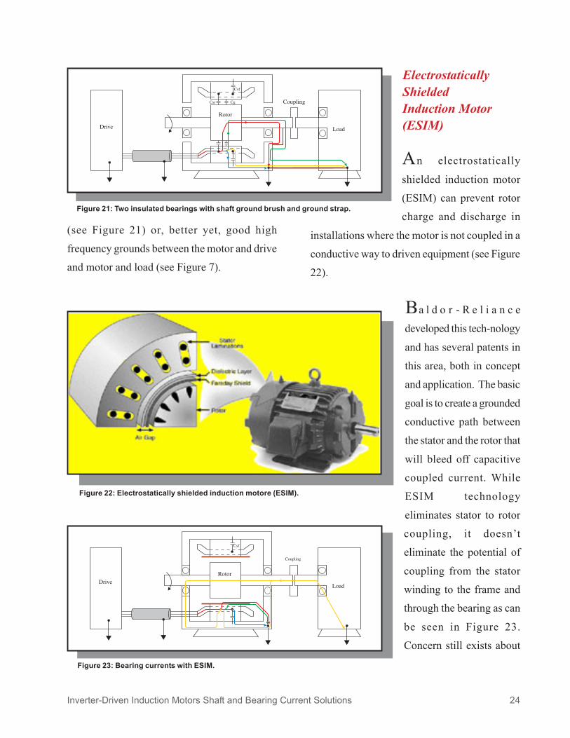
Figure 22: Electrostatically shielded induction motore (ESIM).
ElectrostaticallyShieldedInduction Motor(ESIM)
An electrostatically
shielded induction motor
(ESIM) can prevent rotor
charge and discharge in
installations where the motor is not coupled in a
conductive way to driven equipment (see Figure
22).
developed this tech-nology
and has several patents in
this area, both in concept
and application. The basic
goal is to create a grounded
conductive path between
the stator and the rotor that
will bleed off capacitive
coupled current. While
ESIM technology
eliminates stator to rotor
coupling, it doesnít
eliminate the potential of
coupling from the stator
winding to the frame and
through the bearing as can
be seen in Figure 23.
Concern still exists about
Figure 21: Two insulated bearings with shaft ground brush and ground strap.
Figure 23: Bearing currents with ESIM.
Ba l d o r - R e l i a n c e

connections from the stator core to the conduit
box ground stud are also standard practice.
For small and medium AC motors, bearings
can be insulated and ground brushes applied and
an electrostatically shielded product is available.
bearing technologies that create an insulating
barrier between the frame of the motor and the
outer race of the bearing (see Figure 25). The
Inverter-Driven Induction Motors Shaft and Bearing Current Solutions 25
the currents that
might flow from the
stator core through
the motor bearings
and shaft into the
driven equipment
due to poor high
frequency ground
paths for common
mode current produced by the inverter. Figure
24 shows how the addition of a motor/load
ground strap can protect load bearings by
shunting the currents away from the bearings in
the entire system. Also, a good high frequency
ground between the motor and drive is another
solution (see Figure 7).
Standard Practice ForBearing Protection
with inverters. On large AC
motors, insulated bearings are
provided on the drive end and
opposite drive end, as well as a
grounding brush (see Figure 26),
on either the drive end or opposite
drive end. For large AC
applications, the grounding brush
is typically installed on the drive
end. Enhanced ground Figure 25: Insulated bearing.
Figure 24: ESIM motor with motor to load groundtrap strap.
Baldor-Reliance has standards
in place for prev ent ing
bear ing cur ren t damage
provides a variety of insulatedBaldor-Reliance
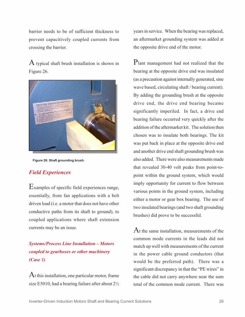
barrier needs to be of sufficient thickness to
prevent capacitively coupled currents from
crossing the barrier.
A typical shaft brush installation is shown in
Figure 26.
Field Experiences
Examples of specific field experiences range,
essentially, from fan applications with a belt
driven load (i.e. a motor that does not have other
conductive paths from its shaft to ground), to
coupled applications where shaft extension
currents may be an issue.
Systems/Process Line Installation ñ Motorscoupled to gearboxes or other machinery
(Case 1)
At this installation, one particular motor, frame
size E5010, had a bearing failure after about 2
years in service. When the bearing was replaced,
an aftermarket grounding system was added at
the opposite drive end of the motor.
Plant management had not realized that the
bearing at the opposite drive end was insulated
(as a precaution against internally generated, sine
wave based, circulating shaft / bearing current).
By adding the grounding brush at the opposite
drive end, the drive end bearing became
significantly imperiled. In fact, a drive end
bearing failure occurred very quickly after the
addition of the aftermarket kit. The solution then
chosen was to insulate both bearings. The kit
was put back in place at the opposite drive end
and another drive end shaft grounding brush was
also added. There were also measurements made
that revealed 30-40 volt peaks from point-to-
point within the ground system, which would
imply opportunity for current to flow between
various points in the ground system, including
either a motor or gear box bearing. The use of
two insulated bearings (and two shaft grounding
brushes) did prove to be successful.
At the same installation, measurements of thecommon mode currents in the leads did notmatch up well with measurements of the currentin the power cable ground conductors (thatwould be the preferred path). There was asignificant discrepancy in that the ìPE wiresî inthe cable did not carry anywhere near the sumtotal of the common mode current. There was
Inverter-Driven Induction Motors Shaft and Bearing Current Solutions 26
Figure 26: Shaft grounding brush.

also a measurable amount of current in a ground
connection to the motor base, implying there was
sufficiently low impedance in that path (relative
to the preferred path) to carry a portion of the
common mode current ñ instead of running it
through the preferred path of the cable ground.
Current flow in the motor shaft extension toward
the driven equipment was measured, and peaks
of 26 amp pulses in the shaft extension were
recorded.
This application demonstrated bearing damage
due to common mode currents flowing through
the drive end bearing and shaft extension to the
driven equipment and also (temporarily)
internally-sourced circulating current.
Case 1A
As a point of
comparison,
another similar
a p p l i c a t i o n
which had a
more rigorous
attention to
c a b l i n g /
g r o u n d i n g /
bonding at installation was also investigated. To
illustrate the common mode currents (CMC)
measured at this preferred installation, upper and
lower traces in Figure 27 are the CMC and the
ground currents, respectively. In both of these
traces, the currents very accurately track one
another, implying that the ground current / CMC
is not taking any undesirable paths. It is in fact
returning through the cable ground conductors,
as is desired.
Inverter-Driven Induction Motors Shaft and Bearing Current Solutions 27
Figure 27: Common mode currentand ground current wave forms.
Trace 1: Ground current. (5 amps/div)
Trace 3 : Common mode current. (5 amps/div)
Systems/Process Line Installation ñ Motorscoupled to gearboxes or other machinery(Case 2)
Yet another application with the motor shaft
extensions conductively coupled to driven
equipment included an installation in which all
of the motor-mounted encoders were applied
with a shaft grounding brush option kit (at the
opposite drive end of all the motors). The failures
were L449 frame motors in which the drive end
bearings failed. Any internally generated
circulating shaft currents would have an easy
time flowing through the drive end bearing
because of the high conductivity path provided
by the grounding brush at the opposite end. Even
if this source of current was non-damaging with
both bearings uninsulated (and no ground brush),
the shaft to frame short circuit at the opposite
drive end of the motor made the bearing at the
drive end more susceptible to damage from
current flow.
There was also the potential for those drive end
bearings to fail because a portion of the common
mode current was not flowing through the
preferred path, but rather one which included
the motor bearing and shaft extension and
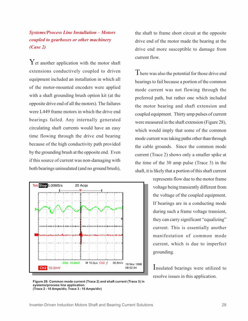
coupled equipment. Thirty amp pulses of current
were measured in the shaft extension (Figure 28),
which would imply that some of the common
mode current was taking paths other than through
the cable grounds. Since the common mode
current (Trace 2) shows only a smaller spike at
the time of the 30 amp pulse (Trace 3) in the
shaft, it is likely that a portion of this shaft current
represents flow due to the motor frame
voltage being transiently different from
the voltage of the coupled equipment.
If bearings are in a conducting mode
during such a frame voltage transient,
they can carry significant ìequalizingî
current. This is essentially another
manifestation of common mode
current, which is due to imperfect
grounding.
Insulated bearings were utilized to
resolve issues in this application.
Inverter-Driven Induction Motors Shaft and Bearing Current Solutions 28
Figure 28: Common mode current (Trace 2) and shaft current (Trace 3) insystems/process line application.(Trace 2 - 10 Amps/div, Trace 3 - 10 Amps/div)

Systems/Process Line Installation ñ Motorscoupled to gearboxes or other machinery(Case 3)
Another installation where bearings failed due
to current flow was again an application with
motors conductively coupled to well-grounded
gearboxes and massive machinery with multiple
conductive paths from the shaft to ground. When
shaft voltages were measured, there was no
detectable voltage (to ground) on the motor
shafts. This implied that the driven equipment
was providing a very low impedance path to
ground that was keeping the motor shaft from
developing a voltage. There was not a bond from
the motor frame to the gearbox, which was later
corrected. The motors were built with an
Opposite Drive End insulated bearing.
Consequently, it was the Drive End bearing that
failed.
HVAC Application ñ Motors coupled to fansvia non-conductive belts(Case 4)
In this particular application, there were 10 air
handling systems which were all controlled by
ìvariable speed.î Each of those had a supply
fan, as well as a return fan. A small number of
failures were concentrated in just a few of the
locations in this building. Motor wiring consisted
of loose (individual) wires with just a single
ground, no shield, randomly drawn through
conduits. This would be a common wiring
practice for line-powered (sine wave)
applications. Because of the pivoting motor
bases (for belt tensioning), the last 10 feet or so
of each of the conduit runs used the flexible,
spiral interlocked conduit that is not a good high
frequency ground path.
At this installation, each of the inverters had
an isolation transformer providing the AC input.
Of those isolation transformers, a number of
them had the secondary XO connection floating
and others had the connection hard grounded.
They were all shielded type transformers. All of
the failures were on cases where the XO was
grounded, even though the shaft voltage
measured wasnít remarkably higher than other
installations that had not failed.
Tests were conducted to check the extent to
which the conduit was participating in carrying
ground current (compared to the ground lead in
the conduit). By disconnecting the flex conduit
at the motor junction box and pulling it back,
there was significant arcing and sparking, which
implied that the conduit significantly participated
in carrying the ground current.
The isolation transformers were set up so that
all had the floating secondary as a part of the
solution at this installation.
Inverter-Driven Induction Motors Shaft and Bearing Current Solutions 29

Continuing Areas of Research
development projects underway include the
building of motor/drive system simulation
models that predict shaft voltage and bearing
current. It is our goal to predict rotor shaft voltage
based upon a motor/drive model and the motor
design geometry. Initial efforts have focused on
the measurement of the motor and bearing
impedance and the development of a system
model that enables accurate shaft voltage
prediction. This measurement and modeling has
initially been developed using a 30 HP inverter
duty motor.
The Motor Shaft Voltage model proposed
includes two branches (see Figure 29). The top
branch, Zsf, represents the three-phase winding
impedance to the stator frame. The bottom
branch, Zsr, represents the coupling impedance
from the stator winding to the rotor. Additionally,
a model is needed to represent the airgap (Zg),
as well as bearing and grease behavior (Zb). To
utilize the proposed model, these four frequency-
dependent circuit branch impedances must be
established. To accommodate the broad
frequency band occurring in the drive system,
an LCR (inductance, capacitance, resistance)
meter is used to measure impedance for
frequencies up to the kHz range, and a network
analyzer is employed to measure impedances in
the MHz frequency range.
The stator winding to frame coupling
impedance, Zsf, is measured between the three
stator windings (with shorted terminals) and the
motor frame, with the rotor end bells removed.
Each winding then has three times the magnitude
and the same phase as the measured impedance.
The measured magnitude
and phase of Zsf is shown in
Figure 30.
Inverter-Driven Induction Motors Shaft and Bearing Current Solutions 30
Figure 29: Motor shaft voltage equivalent circuit model.
Figure 30: Stator winding to frame impedance.
Baldor - RelianceCurrent technology
A sub-circuit is then constructed to match the
measured data up to 3 MHz.
The airgap impedance Zg is assumed purely
capacitive, and can be readily calculated as a flat
parallel capacitor. The stator to rotor impedance
Zsr cannot be measured directly, instead it must
be extracted from the Zsf measurement data, the
air gap impedance value and from an LCR meter
reading taken from between the common point
of the shorted stator windings and the rotor. The
bearing impedance Zb is the most difficult one
to quantify because of its nonlinear and
stochastic behavior as a function of rotation
speed, grease temperature and applied voltage.
In the present model, the bearing is modeled as
a capacitor in parallel with a high resistance in
the ìopenî state, while other end effects are
assumed purely capacitive. The LCR meter is
used to measure the impedance between the inner
and the outer race of the bearing, with the rotor
supported by end bells and turned at half rated
speed by an external mover. The magnitude and
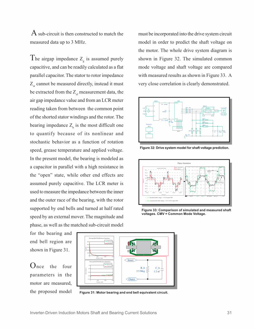
phase, as well as the matched sub-circuit model
for the bearing and
end bell region are
shown in Figure 31.
Once the four
parameters in the
motor are measured,
the proposed model
must be incorporated into the drive system circuit
model in order to predict the shaft voltage on
the motor. The whole drive system diagram is
shown in Figure 32. The simulated common
mode voltage and shaft voltage are compared
with measured results as shown in Figure 33. A
very close correlation is clearly demonstrated.
Inverter-Driven Induction Motors Shaft and Bearing Current Solutions 31
Figure 33: Comparison of simulated and measured shaftvoltages. CMV = Common Mode Voltage.
Figure 31: Motor bearing and end bell equivalent circuit.
Figure 32: Drive system model for shaft voltage prediction.
!

This modeling has proved successful in
predicting motor shaft voltage in the studied
inverter drive system. Direct calculation of the
impedance values as a function of frequency
from motor geometry data is the next challenge
in this modeling effort.
Drive Design Issues
So far, the present paper has focused on shaft
and bearing current mitigation solutions in
induction motors, given that the common mode
voltage and resulting common mode currents are
flowing in the motor. It is important to point out
that reduction of bearing damage caused by these
unwanted current flows is not solely a motor
design issue, but also involves the entire drive
system, including the inverter drive. Special
inverter design topologies, that can eliminate or
reduce the common mode voltage from a variable
speed drive system, can also reduce bearing
current damage.
As outlined previously, the common mode
voltage existing in modern fast-switching IGBT
inverters is largely responsible for the elevated
motor shaft to frame voltage as confirmed in
theory/modeling and by measurement.
Therefore, suppressing the common mode
voltage has to be an important goal in a
successful shaft current mitigation plan for
induc-tion motor drive systems. Three different
drive designs for common mode voltage
reduction will be discussed here. The first
approach consists of working on the modulation
strategy solely by controlling the number and
amplitude of the variations of common mode
voltage, through, for example, a random space
vector modulation technique. This approach is
certainly very enticing since it does not incur
added hardware cost. At present, however, only
up to 50% common mode voltage amplitude
reduction has been shown feasible, along with
desirable spectrum distribution of the common
mode voltage.
The second approach involves a drive topology
change and/or placing a common mode reactor
in series with the motor phases to achieve active
cancellation or passive (low-pass) filtering.
Appreciable common mode voltage reduction is
feasible, but the approach places limitations on
current control capabilities.
The third approach consists of new drive
topologies to achieve elimination of the common
mode voltage. The down side of this approach
lies in increased drive/motor hardware cost,
compared to a conventional drive system.
Three examples of common mode voltage
reduction through drive system topology design
will be explored. Two of them are from the
academic community and one has been presented
by a drive manufacturer.
Inverter-Driven Induction Motors Shaft and Bearing Current Solutions 32

A Four Leg Converter along with a three-phase
RL filter, proposed by the University of
Wisconsin presents the option of
achieving zero common mode
voltage at any moment, the
ultimate desired goal. Prototype
drives have been designed
incorporating this technology.
Figure 34 shows in the top graph
the presence of common mode
voltage in a typical three-phase
design. With four-phase
operation, however, (bottom graph), much lower
common mode voltage is evident.
Another solution, proposed by von Jouanne and
Zhang of Oregon State University, is a Dual
Bridge Inverter Topology. This is a somewhat
more costly option in that it requires two drives.
The dual drives feed each group in a split motor
winding design in such a fashion as to achieve
common mode voltage cancellation. Figure 35
shows a comparison of shaft voltage in a standard
PWM inverter (left) versus a dual bridge inverter
(right) on a 230/460V 5 HP motor. Much lower
shaft voltage is evident.
The third topology was developed by PDL
Electronics, a drive manufacturer, and includes
a motor voltage optimizer filter. The filter design
has been applied in a special environment that
will improve conditions in applications where a
shaft brush cannot be mounted. The filter acts
to reduce the common mode voltage at the motor
terminals.
Conclusion
Bearing currents in electric motors are not new.
Internally sourced circulating currents within the
motor have been known to exist on sine wave
driven motors for over 80 years. Externally
sourced, inverter induced bearing currents due
to common mode voltage are new and present
new challenges. Fortunately, these common
Inverter-Driven Induction Motors Shaft and Bearing Current Solutions 33
Figure 34: Common mode voltage reduction with four-phase inverter system.
Figure 35: Shaft voltage reduction with dual bridge inverter.

system while increasing damaging current flow
in other parts of the system. On a new
installation, a motor with two insulated bearings
and a shaft grounding brush offers the best
AC motors in inverter applications. For new
installations of smaller motors (less than NEMA
440 frame) where there is no direct electrical
connection between the motor and the driven
equipment (i.e. belt driven fans or motors
connected to loads with insulating couplings),
faraday shield or ESIM technology on new
motors (see Figure 22).
On existing installations where potential
bearing current damage is of concern, the
remedies will depend upon the current flow
paths. In some cases, measurements of shaft
voltage and/or current, common mode current
or net cable current, as described in this paper,
will offer insight into what current components
exist in the system. Once the current paths are
identified, Table 3 can be used to determine the
proper retrofit solution. For example, consider
an installation where shaft current is measured
between the motor and the connected equipment.
If the motor has one insulated bearing and a shaft
grounding brush, the remedy would be to add a
bonding strap from the motor to the load or
improve the ground connection between the
Inverter-Driven Induction Motors Shaft and Bearing Current Solutions 34
mode voltage induced bearing currents are not
seen in a vast majority of inverter-driven motor
applications.
Inverter induced bearing currents can flow
through multiple paths within the motor and
coupled equipment system. These paths were
identified in this paper and include 1) through
the air gap to the rotor and through the motor
bearings, 2) through the stator winding to core
insulation, through the motor bearing, through
the drive shaft and to coupled equipment and 3)
through the motor air gap to the rotor down the
drive shaft and through the coupled equipment
to ground. In all of these cases 1) current flows
through what would normally be considered an
electrical insulator and 2) the current is seeking
a return path to the inverter ground from the
motor stator winding.
There are several methods to reduce or
eliminate damaging bearing currents in an
inverter-driven motor system. Table 3
summarizes remediation methods for various
current flow paths. An X in the table indicates
that the remedy, by itself, will reduce or eliminate
bearing damage due to that particular component
of bearing current. As is shown in the table, no
single motor construction or system installation
method will remedy all bearing current
components. Also, note that some remediation
methods may reduce currents in one part of the
protection against bearing currents.
provides this solution on all large
Baldor-
Reliance
Baldor-Reliance provides the patented

Table 3: Bearing Current Remediation for Motor and Coupled Equipment
REMEDY
Internal, circulating,due to magneticdissymmetry leadingto net flux linkingshaft (fundamentalfrequency or sinewave). Generallyoccurs on motorsabove NEMA 400frame.
Figure 2
Wellterminated
cablegroundconnec-
tions:drive tomotor
Bondingstrap
betweenmotor andload frame
Oneinsulated
motorbearing
onoppositedrive end
Twoinsulated
motorbearings
Shaftgrounding
brushacross
one motorbearing
Faradayshield(ESIM)
Insulatedcouplingbetween
motor anddrivenload
Source of Current
Common mode(ground) current(induced by commonmode dv/dt) taking areturn path via themotor shaftextension andcoupled equipment.
Figure 4 ñ goldcurrent
Discharge throughbearing ofcapacitively-coupledcommon modevoltage (scaled bycapacitor divider).
Figure 4 ñ red andgreen current
X X
X
Avoidwithout
oppositebearing
insulated
Avoidwithout
insulatedcoupling or
bondingstrap
betweenmotor and
load toprotectdriven
equipment
X X X
X X
May causeincreased
motorbearingcurrentwithout
motor shaftgroundbrush,
faradayshield orinsulated
motorbearings
Only if incombinationwith motor
shaft groundbrush orinsulatedcoupling
Only if incombinationwith motor
shaft groundbrush
X indicates that the remedy will, by itself, reduce or eliminate motor bearing current damage and currentflow to coupled equipment.Inverter-Driven Induction Motors Shaft and Bearing Current Solutions 35

based on high frequency impedance modeling
of a motor and inverter system.
At the same time, inverter manufacturers and
other research centers continue to investigate
methods to reduce the common mode voltage
and current in inverter-driven motor systems. A
few examples were given here. Unfortunately
methods identified to date require considerable
added costs to the inverter and are, therefore,
commercially not viable. Until an inverter
topology is developed that will eliminate the
source of the high frequency bearing currents,
remediation methods will continue to be
concentrated at the motor and system installation.
Inverter induced bearing currents continue to
be studied. More and more information is being
gathered through diagnostic measurements in
applications where bearing damage has occurred.
A clear understanding of potential current paths
in a given installation is required in order to select
the proper remediation method. With the proper
remediation method applied, bearing current
damage can be reduced or eliminated.
Inverter-Driven Induction Motors Shaft and Bearing Current Solutions 36
motor and the inverter.
Most applications do not have bearing current
problems. Of the thousands of inverter-driven
motors out there, problems have occurred with
only a few. But still it is an issue that causes
concern. There is still more to learn. There is
no standard, no well-known direct relationship
between bearing voltage magnitude and bearing
damage. In fact, there are applications in which
there may be no voltage measured across the
bearing, but damage still occurs because of
quasi-continuous current.
Bearing electrical models are not yet fully
developed. In fact, measurements have been
made in which the bearing characteristics change
with speed and with temperature.
No standard test methods exist to evaluate
bearing current problems, and one of the key
aspects associated with that is the inability to
directly measure bearing current. High
frequency current paths in many installations are
not well understood. High frequency motor
models are not well developed. This is an area
that has generally been ignored.
methods to model the common mode circuit in
inverter-driven motor systems. Results shown
here indicate our ability to predict shaft voltage
Baldor-Reliance continues to study

Inverter-Driven Induction Motors Shaft and Bearing Current Solutions 37
References
••••• J. M. Erdman, Russel J. Kerkman, David W. Schlegel and Gary L. Skibinski, ìEffect of PWM Inverterson AC Motor Bearing Currents and Shaft Voltages,î IEEE Applied Power Electronics Conference (APEC),Dallas, TX, March 6-9, 1995, pp. 24-33. IEEE Transactions on Industry Applications, Vol. 32, No. 2,March/April 1996, pp. 250-259.
••••• Doyle Busse, Jay Erdman, Russel J. Kerkman, Dave Schlegel, and Gary Skibinski, ìBearing Currentsand Their Relationship to PWM Drives,î IEEE Industrial Electronics Conference (IECON), Orlando, FL,Nov. 6-10, 1995, pp. 698-705. IEEE Transactions on Power Electronics, Vol. 12, No. 2, March 1997, pp.243-252.
••••• Doyle Busse, Jay Erdman, Russel J. Kerkman, Dave Schlegel and Gary Skibinski, ìThe Effects of PWMVoltage Source Inverters on the Mechanical Performance of Rolling Bearings,î IEEE Applied PowerElectronics Conference (APEC), San Jose, CA, March 3-7, 1996, pp. 561-569. IEEE Transactions onIndustry Applications, Vol. 33, No. 2, March/April 1997, pp. 567-576.
••••• Doyle Busse, Jay Erdman, Russel J. Kerkman, Dave Schlegel and Gary Skibinski, ìSystem ElectricalParameters and Their Effects on Bearing Currents,î IEEE Applied Power Electronics Conference (APEC),San Jose, CA, March 3-7, 1996, pp. 570-578. IEEE Transactions on Industry Applications, Vol. 33, No.2, March/April 1997, pp. 577-584.
••••• Doyle Busse, Jay Erdman, Russel JKerkman, Dave Schlegel and Gary Skibinski, ìAn Evaluation of theElectrostatic Shielded Induction Motor: A Solution for Rotor Shaft Voltage Buildup and Bearing Current,îIEEE Industry Application Society Conference, San Diego, CA, October 6-10, 1996, pp. 610-617. IEEETransactions on Industry Applications, Vol. 33, No. 6, November/December 1997, pp. 1563-1570.
••••• R. Kerkman, D. Schlegel and G. Skibinski, ìAn Examination of Rotor Shaft Voltage and the ResultingBearing Current: A Consequence of PWM Inverter Operation,î IEEE Industry Applications Magazine,Vol. 3, No. 6, November/December 1997, pp. 21-32.
••••• D. Schlegel, R. Kerkman and G. Skibinski, ìTurning The Tables On Shaft Voltage And Bearing Cur-rents,î EC&M, June 1998, pp. 60-71.
••••• Sidney Bell, Timothy J. Cookson, Steven A. Cope, Richard A. Epperly, Annika Fischer, David W. Schlegeland Gary L. Skibinski, ìExperience With Variable Frequency Drives and Motor Bearing Reliabilityî, IEEEIAS Petroleum and Chemical Industry Conference (PCIC), Indianapolis, IN, Sept. 28-30, 1998.

Inverter-Driven Induction Motors Shaft and Bearing Current Solutions 38
The discussion of PWM inverter-sourced bearingcurrents inevitably involves some discussion ofgrounding. While ìgroundingî in the classic senseof a conductor to ìearth groundî is an issue, it is notthe major one. The first issue is the provision of alow impedance path (within the power lead cable)for the safe return of common mode currents to theinverter. This is best done by the ground and shieldconductors in the power cable, so it could be calledìproperly grounding the motor.î However, it is NOTequivalent to a good ìsafety groundî of the motorto earth. It might be better described as ìbondingîthe motor ground to the inverter ground (via a goodhigh frequency path).
Also in regard to bonding, another considerationis bonding to equalize potentials (on a transientbasis) between points within the ground system. Animportant location for such bonding is between the
Appendix 1: Grounding/Bonding
motor frame and the frame of coupled machinery.Non-zero impedances between points in the groundsystem can easily result in transient voltageexcursions that can then drive ground systemcurrents. To avoid these currents utilizing a paththrough bearings and shafts, a ìbond strapî between(interconnected) grounded pieces of equipment canbe used.
Finally, the grounding of the motor frame to theinverter ground needs to be more than just a lowfrequency safety ground. In addition to requiring lowimpedance (at the high frequencies represented byfast rising edges), the ground path should also befree from ìintermittentî ground impedance changes(such as might occur with some types of flexibleconduit). Such changes in ground impedance canresult in higher than normal voltages on bearings.
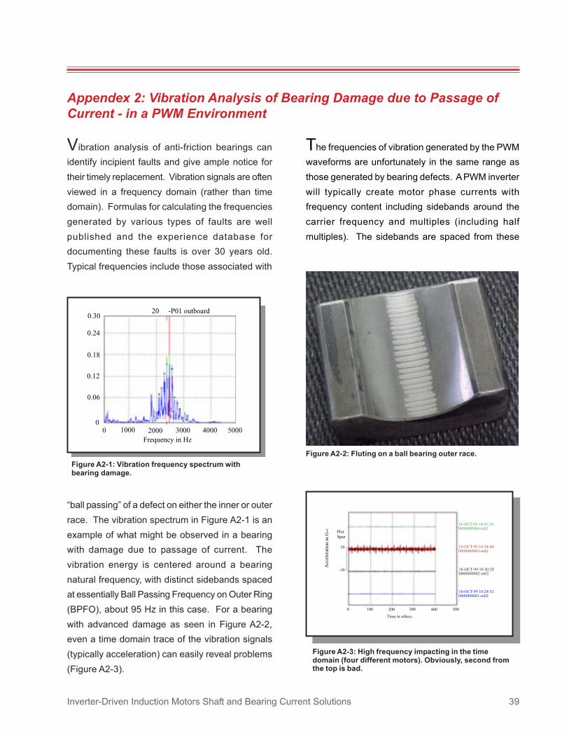
Inverter-Driven Induction Motors Shaft and Bearing Current Solutions 39
Vibration analysis of anti-friction bearings canidentify incipient faults and give ample notice fortheir timely replacement. Vibration signals are oftenviewed in a frequency domain (rather than timedomain). Formulas for calculating the frequenciesgenerated by various types of faults are wellpublished and the experience database fordocumenting these faults is over 30 years old.Typical frequencies include those associated with
ìball passingî of a defect on either the inner or outerrace. The vibration spectrum in Figure A2-1 is anexample of what might be observed in a bearingwith damage due to passage of current. Thevibration energy is centered around a bearingnatural frequency, with distinct sidebands spacedat essentially Ball Passing Frequency on Outer Ring(BPFO), about 95 Hz in this case. For a bearingwith advanced damage as seen in Figure A2-2,even a time domain trace of the vibration signals(typically acceleration) can easily reveal problems(Figure A2-3).
Appendex 2: Vibration Analysis of Bearing Damage due to Passage ofCurrent - in a PWM Environment
Figure A2-2: Fluting on a ball bearing outer race.
The frequencies of vibration generated by the PWMwaveforms are unfortunately in the same range asthose generated by bearing defects. A PWM inverterwill typically create motor phase currents withfrequency content including sidebands around thecarrier frequency and multiples (including halfmultiples). The sidebands are spaced from these
Figure A2-1: Vibration frequency spectrum withbearing damage.
Figure A2-3: High frequency impacting in the timedomain (four different motors). Obviously, second fromthe top is bad.

Inverter-Driven Induction Motors Shaft and Bearing Current Solutions 40
frequencies by plus and minus one, two, and fourtimes the fundamental frequency. Bearing naturalfrequencies (for bearings commonly used in 3 ñ 500HP motors) are typically in a range of 1 ñ 4 kHz.This is also a common range for inverter carrierfrequencies. The sideband spacings of inverteroutput currents and ball passing frequencies are alsooverlapping to the extent that they can be easilyconfused. The non-fundamental frequencies in thecurrent waveform give rise to motor vibrations atthose frequencies. That is a major source of theìPWM humî acoustic noise from PWM inverter-fedmotors. By removing the input power from the motor(while at speed) and letting it coast to rest, thevibrations from the current waveform can beseparated from any that might be present due to
bearing damage.
Diagnosis of Damaged Bearings ñCautions
While the characteristic ìflutedî pattern of damageis a characteristic common to bearings which haveexperienced current flow, it is not correct to assumethat any bearing exhibiting this feature necessarilyhad current flow as theroot cause of thedamage. In fact,damage fromsubsequent runningafter false brinellingcan exhibit a patternsuch as shown inFigure A2-4.
Figure A2-4: Bearing damagefrom running after falsebrinelling.
The reality is that the fluted pattern is the result of
the bearing operating with debris and damage inthe ball track. This can occur with or without currentflow as a root cause. One way to distinguishbetween fluting caused by current versus othersources is to examine the race area microscopically.By etching a polished cross section of the affectedarea, a thin surface layer of rehardened material(untempered martensite - which is caused by theextreme heat of interrupted current flow ordischarge) can be identified. This can only be seenmicroscopically. This micro-structure would not bepresent in a bearing which was damaged by falsebrinelling. Another sign that current flow may be aroot cause of a particular case of a fluted bearing isthe appearance of the rolling elements. Balls orrollers that have been involved in current damagetypically have a dull, frosted appearance, and are
normally not shiny (grind marks are not visible).
Inverter-Driven Induction Motors Shaft and Bearing Current Solutions 41
Motor bearing currents due to inverter excitation arethe result of current flow through parts of the motorthat can be modeled as capacitors. These includethe electrical insulation materials (slot liners, magnetwire enamel, insulating varnish or resin), the motorair gap and the lubricant film between the bearingballs and races.
A capacitor is a passive circuit element that obeysthe following relationship between the voltage acrossthe capacitor (v) and the current through it (i):
i = C dv/dt (1)
where C is the capacitance and dv/dt is the rate ofchange of voltage with respect to time (instantaneousslope of the voltage versus time waveform).
Capacitors consist of two conducting surfacesseparated by an insulating layer. If each of the twoconducting surfaces has surface area equal to A andtwo surfaces are separated by a distance d, then:
C = !0!¥A/d (2)
where !0 is the permitivity of vacuum and ¥ is thedielectric constant of the material in the insulatinglayer. Typical dielectric constants for insulatingmaterials in an electric motor (slot liners, magnet wireenamel) are in the range of 2 to 10. The dielectricconstant of air is 1. Bearing lubricants have dielectricconstants in the range of 2 to 5.
Another way to look at the magnitude of current flowthrough a capacitor is to consider its AC impedance.The impedance of a circuit element is the resistanceto current flow when alternating currents flow through
Appendix 3: Capacitor Current Flow
the element. The impedance of the capacitor is afunction of the frequency of the applied voltage.
Consider the current and voltage relationship for thecapacitor in equation (1). If the voltage applied is aconstant frequency sine wave with peak value Vm
and frequency f then:
v(t) = Vmsin(2"ft) (3)
and the capacitor current will be:
i = C2"fVm cos(2"ft) = Vmcos(2"ft)/Zc (4)
The capacitor is seen to have an AC impedance of:
Zc = 1/(2"fC) (5)
The capacitive current flow is therefore directlyproportional to the frequency of the applied voltageand the capacitive impedance is inverselyproportional to the applied frequency. With the fastswitching speeds (transistor turn-on and turn offtimes) of todayís inverters, high frequency contentvoltage waveforms are applied to the motor terminalswhich results in increased capacitive current flow withthe potential for damaging current flow in the motorbearings.
The magnitude of current flow through capacitivepaths within the motor depends upon the rate ofchange of voltage and the value of capacitance inthat circuit path as shown in equation (1). Noticethat the faster the voltage across the capacitorchanges with time, the larger the magnitude of thecurrent through that element. From equation (2) thevalue of capacitance is inversely proportional to the
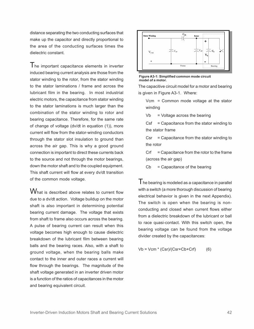
Inverter-Driven Induction Motors Shaft and Bearing Current Solutions 42
distance separating the two conducting surfaces thatmake up the capacitor and directly proportional tothe area of the conducting surfaces times thedielectric constant.
The important capacitance elements in inverterinduced bearing current analysis are those from thestator winding to the rotor, from the stator windingto the stator laminations / frame and across thelubricant film in the bearing. In most industrialelectric motors, the capacitance from stator windingto the stator laminations is much larger than thecombination of the stator winding to rotor andbearing capacitance. Therefore, for the same rateof change of voltage (dv/dt in equation (1)), morecurrent will flow from the stator-winding conductorsthrough the stator slot insulation to ground thanacross the air gap. This is why a good groundconnection is important to direct these currents backto the source and not through the motor bearings,down the motor shaft and to the coupled equipment.This shaft current will flow at every dv/dt transitionof the common mode voltage.
What is described above relates to current flowdue to a dv/dt action. Voltage buildup on the motorshaft is also important in determining potentialbearing current damage. The voltage that existsfrom shaft to frame also occurs across the bearing.A pulse of bearing current can result when thisvoltage becomes high enough to cause dielectricbreakdown of the lubricant film between bearingballs and the bearing races. Also, with a shaft toground voltage, when the bearing balls makecontact to the inner and outer races a current willflow through the bearings. The magnitude of theshaft voltage generated in an inverter driven motoris a function of the ratios of capacitances in the motorand bearing equivalent circuit.
The capacitive circuit model for a motor and bearingis given in Figure A3-1. Where:
Vcm = Common mode voltage at the statorwinding
Vb = Voltage across the bearing
Csf = Capacitance from the stator winding tothe stator frame
Csr = Capacitance from the stator winding tothe rotor
Crf = Capacitance from the rotor to the frame(across the air gap)
Cb = Capacitance of the bearing
The bearing is modeled as a capacitance in parallelwith a switch (a more thorough discussion of bearingelectrical behavior is given in the next Appendix).The switch is open when the bearing is non-conducting and closed when current flows eitherfrom a dielectric breakdown of the lubricant or ballto race quasi-contact. With this switch open, thebearing voltage can be found from the voltagedivider created by the capacitances:
Vb = Vcm * (Csr)/(Csr+Cb+Crf) (6)
Figure A3-1: Simplified common mode circuitmodel of a motor.

Inverter-Driven Induction Motors Shaft and Bearing Current Solutions 43
The relative magnitudes of the capacitive circuitelements in Equation (6) are a function of air gaplength and other critical motor dimensions that areoptimized to provide desired motor efficiency orinsulation system life. Dramatic changes in the ratioof bearing voltage to common mode voltage aredifficult to attain through simple motor dimensionchanges without adversely affecting motorperformance. For this reason, add on features suchas insulated bearings, shaft grounding brushes and/or electrostatic shielding are required to reduce theimpact of the shaft voltage buildup and the resultingdischarge on motor bearing life.

Inverter-Driven Induction Motors Shaft and Bearing Current Solutions 44
Appendix 4: Rolling Bearing Electrical BehaviorsBearings in most cases are not designed to carryelectric current. They are, however, called upon todo so in motor drive applications in which they areunintentionally subject to various sources of electricpotential, as discussed in this article. The currentthrough a motor bearing depends mainly on themagnitude of the shaft voltage and bearingimpedance in the corresponding frequency range.The bearing impedance, in turn, depends on thelubricant properties, bearing geometry, bearingtemperature, load, operating speed, and others.
According to electric contact theory, surface contactcan be made in three ways. 1. Metal to metal contactñ electric current flows with negligible resistance. 2.Quasi-metallic contact ñ surfaces are separated bya molecular layer of oxides and the electric currentflows through with little resistance (0.3 ~ 0.5#) bythe quantum-mechanical tunneling effect. 3. Contactthrough a layer of relatively thick film ñ resistancewill be normally high depending on the lubricant filmthickness and resistivity. The rolling element-to-racecontact in a stationary bearing is of quasi-metallictype, and the relatively large contact area can carrya strong current without any damage. In a rotatingbearing, the rolling elements and race areseparated, at most times, by a layer of lubricant;since, for example, the average lubricant filmthickness is calculated to be 0.1 ~ 2 mm for a rollerbearing based on elastohydrodynamic theory. Theactual contact area in a rotating bearing, however,will depend largely on the surface roughness and iscomprised primarily of ëasperity contactí which maybe estimated by the Herzian point contact theory.
It has been demonstrated that the AC impedanceof parallel metal-lubricant interfaces may bedescribed by three parallel R-C circuits in a series
connection. One of the R-C circuits represents thebulk lubricant behavior, while the other two describethe metal-lubricant interfacial electrochemicalinteraction. This approach can be adapted to studyrolling bearing and lubricant electrical behavior. Thebearing capacitance can be calculated using thecontact width and minimum film thickness basedon particular bearing geometry, and lubricantdielectric constant. The bearing resistance can becalculated at the same time using lubricantresistivity. Recent research however has indicatedthat the resistivity of typical commercial lubricantsused in motor bearings is highly unstable under thestress of an applied electric field. An electric fieldexists in the lubricant whenever a voltage appearsacross the lubricant film (or from shaft to ground ina motor). Some lubricants may ërecoupí theirresistivity after the electric field is switched off, whileothers may not recover their resistivity after a longtime. These changes in resistivity with appliedvoltage level and running time may be attributableto the nature of impurities and types of additives inthe lubricant, besides its structure, density andcompressibility.
Based on this analysis, the general electricalbehavior of a rolling bearing may be described byan equivalent circuit shown at right. In this model,Zinner and Zouter are parallel R-C circuits representinginner and outer rolling-race interfaces, respectively.Zo and Zi represent the bulk lubricant and interfaces,respectively. Rir, Ror and Rball are metal resistancesof inner and outer races, and balls/rollers,respectively. Bearing balls may momentarily contactthe races at the asperity contacts thus effectivelyshort the bearing. This random behavior is describedby a switch-like nonlinear resistor Zcontact.

Inverter-Driven Induction Motors Shaft and Bearing Current Solutions 45
Essentially, the bearing acts like a resistive-capacitive (R-C) circuit when a voltage is appliedacross it. In a rotating bearing, the location of thebearing balls and resistive state of the bearinglubricant causes the bearing resistance andcapacitance to change with time. The randomcontact of the bearings balls to the races as well asthe highly unpredictable resistance behavior of thebearing grease make reliable prediction of bearingcurrent difficult, even if the shaft to frame voltage isknown.
Figure A4-1: General electrical behavior of a rolling

World HeadquartersP.O. Box 2400, Fort Smith, AR 72902-2400 U.S.A., Ph: (1) 479.646.4711, Fax (1) 479.648.5792, International Fax (1) 479.648.5895
www.baldor.com© Baldor Electric Company
RAPS-868
All Rights Reserved. Printed in USA.
7/07-K-00M
Top Related