


Languages
Pages
Legal


INTRODUCTION 4
The Company ............................................................................................................4 Aftersales .................................................................................................................. 5 Maintenance and Field Services .................................................................................. 5 Complete Solutions Strategy ...................................................................................... 7
VALVES 8
Ball Valves - TVE ...................................................................................................... 10 Subsea Ball Valves - TVE........................................................................................... 18 Needle Valves – TVB ................................................................................................ 22 High Pressure Needle Valves - THP ............................................................................ 36 Pressure Relief Valves – TVA ..................................................................................... 40 Gate Valves - TGV .................................................................................................... 44 Pressure Control Valves - TWO .................................................................................. 48 High Flow High Pressure Control Valves - TRT ............................................................ 50 Shuttle Valves - TSV................................................................................................. 52 Pneumatic Pilot Valves - TPV .................................................................................... 56 High-Low Pilot Valves - THL ..................................................................................... 58 Check Valves - TCV................................................................................................... 60 High Flow Check Valves - TRV ................................................................................... 64 Quick Exhaust Valve - TER ........................................................................................ 66 Directional Valves - TVS ........................................................................................... 68 Subsea Directional Valves - TVS ................................................................................ 72 Piloted Directional Valves - THM ............................................................................... 74
AUXILIARY HYDRAULIC INSTRUMENTATION 76
Hydraulic Filters - TDA ............................................................................................. 78 Quick Couplings - TEN .............................................................................................. 84 Manifolds - TMA ...................................................................................................... 86 Thermal Fuse Plug - TFT ........................................................................................... 91 Hydropneumatic Pumps - TBO .................................................................................. 92 Gas Boosters - TBO .................................................................................................. 94
TRANSMITTERS AND DATA ACQUISITION 96
Pressure and Temperature Transmitters – TPT ........................................................... 98 Permanent Downhole Gauge - PDG ......................................................................... 106 Downhole Gauge- TTP ........................................................................................... 110 Coaxial Electrical Cable Splice - TEE......................................................................... 112 V-Cone Flow Meter - TMV ....................................................................................... 114 IWIS / Universal PDG Interface Card- TLE ................................................................. 116 Signal Acquisition System (SAS) - TLE ..................................................................... 117 Portable Signal Acquisition System (SASP) - TLE...................................................... 118 Mobile Subsea Signal Acquisition System (SSAS) - TSI .............................................. 119 Independent Subsea Signal Acquisition System (SASMI) - TSI ................................... 120 Compact Independent Subsea Signal Acquisition System (SASMIcIr) - TSI .................. 121 Subsea Electrical Monitoring System - TSE .............................................................. 122

HYDRAULIC SYSTEMS AND COMPONENTS 124
Quick Unlocking System - TSD ................................................................................ 126 Hydraulic Plates – TPH ........................................................................................... 128 Hydraulic Flying Lead – HFL .................................................................................... 132 Hydraulic Actuators – TSE ...................................................................................... 134 Hot Stab – THS ...................................................................................................... 136 R.O.V. Subsea Control Panels - TPC ......................................................................... 139 Hydraulic Units and Control Panels – TUF / TPC ........................................................ 140
SERVICES 142
Hydraulic Power Unit and Control Panel Maintenance .............................................. 144 Flushing Services ................................................................................................... 144 Equipment Testing and Qualification ...................................................................... 145 Instrumentation Calibration ................................................................................... 145 Special Machining Services ..................................................................................... 146 Hyperbaric Chamber Testing .................................................................................. 146 Hydraulic Signature and Gate Valve Override (up to 1") Testing ................................. 147 Cladding Services ................................................................................................... 147 Field Installation Services ....................................................................................... 147
INDEX 148
8
76
Transcontrol Catalog 2016 Edition – Rev. 01
INTRODUCTION
4
INTRODUCTION
THE COMPANY
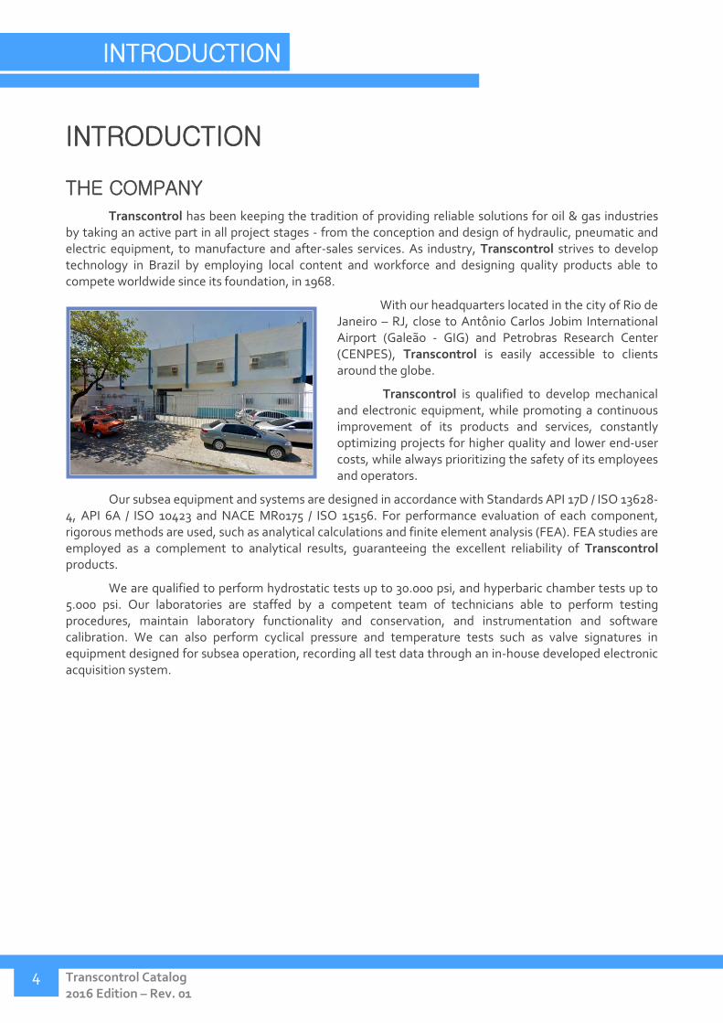
Transcontrol has been keeping the tradition of providing reliable solutions for oil & gas industries by taking an active part in all project stages - from the conception and design of hydraulic, pneumatic and electric equipment, to manufacture and after-sales services. As industry, Transcontrol strives to develop technology in Brazil by employing local content and workforce and designing quality products able to compete worldwide since its foundation, in 1968.
With our headquarters located in the city of Rio de Janeiro – RJ, close to Antônio Carlos Jobim International Airport (Galeão - GIG) and Petrobras Research Center (CENPES), Transcontrol is easily accessible to clients around the globe.
Transcontrol is qualified to develop mechanical and electronic equipment, while promoting a continuous improvement of its products and services, constantly optimizing projects for higher quality and lower end-user costs, while always prioritizing the safety of its employees and operators.
Our subsea equipment and systems are designed in accordance with Standards API 17D / ISO 13628-4, API 6A / ISO 10423 and NACE MR0175 / ISO 15156. For performance evaluation of each component, rigorous methods are used, such as analytical calculations and finite element analysis (FEA). FEA studies are employed as a complement to analytical results, guaranteeing the excellent reliability of Transcontrol products.
We are qualified to perform hydrostatic tests up to 30.000 psi, and hyperbaric chamber tests up to 5.000 psi. Our laboratories are staffed by a competent team of technicians able to perform testing procedures, maintain laboratory functionality and conservation, and instrumentation and software calibration. We can also perform cyclical pressure and temperature tests such as valve signatures in equipment designed for subsea operation, recording all test data through an in-house developed electronic acquisition system.

Phone no.: +55 21 3976-9929 www.transcontrol.com.br
5
AFTERSALES
Transcontrol Comércio e Indústria de Produtos Eletrônicos Ltda offers ample after sales support to clients, throughout our products' lifecycle.
The company's client-supplier communication infrastructure includes technical assistance, conferences and troubleshooting services, aimed towards process optimization and project fulfillment.
MAINTENANCE AND FIELD
SERVICES
The equipment used in oil & gas industries are precision systems that require competent and specialized maintenance. Thus, as Transcontrol manufactures exceptional products, we compromise to offer the best maintenance services as well.
Our technical assistance is managed by highly trained personnel. Our hydraulic and electronic laboratories are equipped with custom designed testing units and precise measurement systems, allowing our maintenance team to quickly identify and resolve any technical issues in the equipment or system. Transcontrol stands prepared to offer an agile response, aiming to fulfill any client requirement or supply and install spare parts for our products, whether in onshore or offshore facilities.
Transcontrol Comércio e Indústria de Produtos Eletrônicos Ltda. Ourique Road, 415, 536 – Penha Circular Rio de Janeiro – ZIP code: 21011-130 – RJ Phone: +55 (21) 39769929 Home Page: www.transcontrol.com.br

Transcontrol Catalog 2016 Edition – Rev. 01
INTRODUCTION
6
Hydraulic Power Units
Hydraulic Control Panels
Signal Acquisition
Interface
Portable Signal Acquisition
Interface
1" and 1/2" Gate Valves
R.O.V. Operated Valves
Multiplexed Subsea Electric Acquisition Systems
Hydraulic Plates
Pressure and Temperature Transmitters
Independent Acquisition Systems
Quick Release Systems
High Volume Flow Meters
Permanent Downhole Gauges
Phone no.: +55 21 3976-9929 www.transcontrol.com.br
7
COMPLETE SOLUTIONS STRATEGY
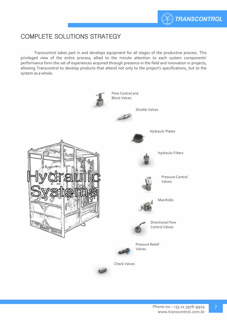
Transcontrol takes part in and develops equipment for all stages of the productive process. This privileged view of the entire process, allied to the minute attention to each system components' performance form the set of experiences acquired through presence in the field and innovation in projects, allowing Transcontrol to develop products that attend not only to the project's specifications, but to the system as a whole.
Shuttle Valves
Flow Control and Block Valves
Hydraulic Plates
Hydraulic Filters
Pressure Control Valves
Manifolds
Directional Flow Control Valves
Pressure Relief Valves
Check Valves

VALVES
Transcontrol Catalog 2016 Edition – Rev. 01
VALVES
8
VALVES
Ball Valves - TVE 10
Subsea Ball Valves - TVE 18
Needle Valves – TVB 22
High Pressure Needle Valves - THP 36
Pressure Relief Valves – TVA 40
Gate Valves - TGV 44
Pressure Control Valves - TWO 48
High Flow High Pressure Control Valves - TRT 50
Shuttle Valves - TSV 52
Pneumatic Pilot Valves - TPV 56
High-Low Pilot Valves - THL 58
Check Valves - TCV 60
High Flow Check Valves - TRV 64
Quick Exhaust Valve - TER 66
Directional Valves - TVS 68
Subsea Directional Valves - TVS 72
Piloted Directional Valves - THM 74
VALVES
Phone no.: +55 21 3976-9929 www.transcontrol.com.br
9
From Project to Platform
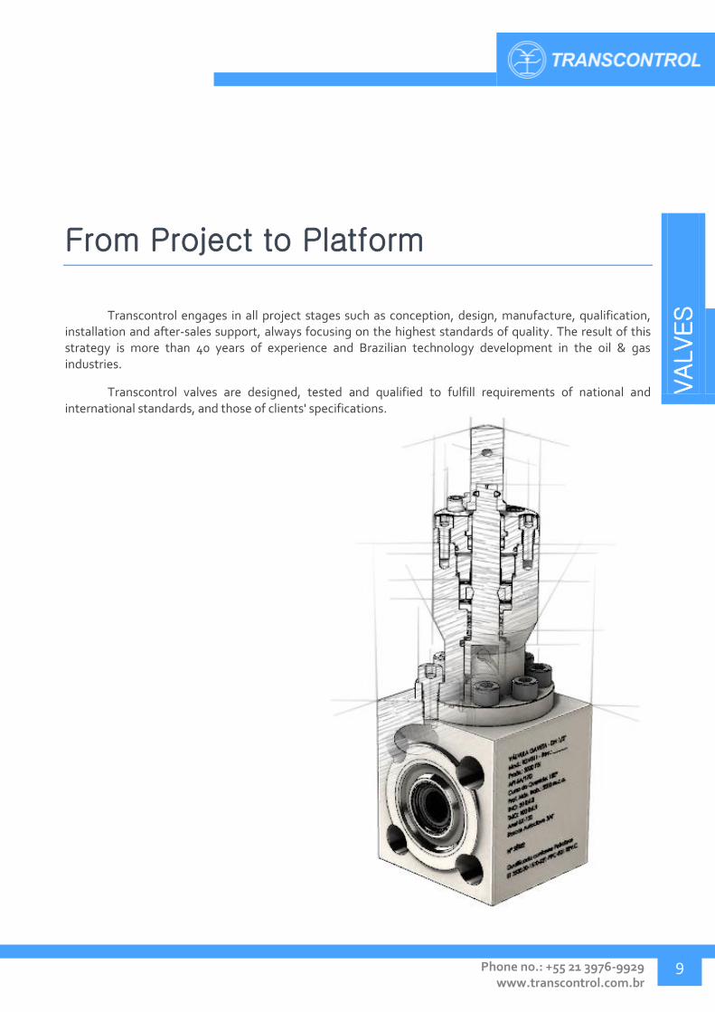
Transcontrol engages in all project stages such as conception, design, manufacture, qualification, installation and after-sales support, always focusing on the highest standards of quality. The result of this strategy is more than 40 years of experience and Brazilian technology development in the oil & gas industries.
Transcontrol valves are designed, tested and qualified to fulfill requirements of national and international standards, and those of clients' specifications.

VALVES
Transcontrol Catalog 2016 Edition – Rev. 01
VALVES
10
BALL VALVES - TVE
TVE Ball valves are indicated whenever rapid blocking of liquid, gas or vapor flow is required. A stainless steel ball, supported by soft seats ensures fast and smooth movement.
Ball valves with more than two ways are commonly used for directional flow control.
Application:
Recommended for flow block and control in liquid, gas or vapor lines. Subsea application for some models using R.O.V. interfaces.
Technical Specification:
Pressure rating: up to 10.000 PSI.
Temperature range: 4° to 65º C.
Connectors: Threaded (NPT), Tubing ferrule (OD), BSP, SW (welded).
Materials: ASTM A351 GR CF8m cast stainless, AISI 316 and carbon steel (contact for others).
Sealing type: Soft Seal (Peek, KEL-F, PTFE).
Model Work pressure
(psi) Ways /
positions Inlet
connector Outlet
connector Body material Stem material
Hydraulic diagram
TVE001 5000 2/2 3/8" NPT-F 3/8" NPT-F ASTM A351 GR
CF8m ASTM A564 tp630
TVE002 5000 2/2 3/8" OD 3/8" OD ASTM A351 GR
CF8m ASTM A564 tp630
TVE003 5000 2/2 1/2" NPT-F 1/2" NPT-F ASTM A351 GR
CF8m ASTM A564 tp630
TVE004 5000 2/2 1/2" OD 1/2" OD ASTM A351 GR
CF8m ASTM A564 tp630
TVE005 5000 2/2 1/4" NPT-F 1/4" NPT-F ASTM A351 GR
CF8m ASTM A564 tp630
TVE006 5000 2/2 1/4" OD 1/4" OD ASTM A351 GR
CF8m ASTM A564 tp630
TVE007 5000 2/2 3/4" NPT-F 3/4" NPT-F ASTM A351 GR
CF8m ASTM A564 tp630
TVE008 6000 2/2 1/2" NPT-F 1/2" NPT-F ASTM A351 GR
CF8m ASTM A564 tp630
TVE009 10000 2/2 1/4" NPT-F 1/4" OD AISI 316 ASTM A564 tp630
TVE010 10000 2/2 1/2" OD 1/2" OD AISI 316 ASTM A564 tp630
TVE011 10000 2/2 1/2" NPT-F 1/2" NPT-F AISI 316 ASTM A564 tp630
TVE012 10000 2/2 3/8" NPT-F 3/8" OD AISI 316 ASTM A564 tp630
TVE013 5000 2/2 3/8" NPT-F 3/8" NPT-F ASTM A351 GR
CF8m ASTM A564 tp630
TVE014 5000 2/2 1/2" OD 1/2" OD ASTM A351 GR
CF8m ASTM A564 tp630
TVE015 6000 2/2 3/4" NPT-F 3/4" NPT-F ASTM A351 GR
CF8m ASTM A564 tp630
TVE016 10000 2/2 3/8" NPT-F 3/8" NPT-F AISI 316 ASTM A564 tp630

VALVES
Phone no.: +55 21 3976-9929 www.transcontrol.com.br
11
Model Work pressure
(psi) Ways /
positions Inlet
connector Outlet
connector Body material Stem material
Hydraulic diagram
TVE017 10000 2/2 1/4" OD 1/4" OD AISI 316 ASTM A564 tp630
TVE018 10000 2/2 3/8" OD 3/8" OD AISI 316 ASTM A564 tp630
TVE022 3000 2/2 3/4" NPT-F 3/4" NPT-F AISI 316 AISI 316
TVE024 3000 2/2 1/2" NPT-F 1/2" NPT-F AISI 316 AISI 316
TVE025 5000 2/2 1" NPT-F 1" NPT-F AISI 316 AISI 316
TVE026 10000 2/2 1/4" NPT-F 1/4" OD AISI 316 ASTM A564 tp630
TVE027 10000 2/2 1/2" NPT-F 1/2" NPT-F AISI 316 ASTM A564 tp630
TVE028 10000 2/2 3/8" NPT-F 3/8" OD AISI 316 ASTM A564 tp630
TVE029 500 3/2 3/4" NPT-F 3/4" NPT-F AISI 316 ASTM A564 tp630
TVE030 3000 2/2 1/2" OD 1/2" OD AISI 316 ASTM A564 tp630
TVE031 3000 2/2 1/2" NPT-F 1/2" OD AISI 316 ASTM A564 tp630
TVE035 5000 2/2 3/4" NPT-M 3/4" NPT-M AISI 316 AISI 316
TVE036 6000 2/2 1/4" OD 1/4" OD AISI 316 ASTM A564 tp630
TVE037 6000 2/2 1/4" NPT-F 1/4" NPT-F AISI 316 ASTM A564 tp630
TVE042 5000 2/2 1/4" NPT-F 1/4" OD AISI 316 ASTM A564 tp630
TVE043 5000 2/2 1/4" NPT-F 1/4" NPT-F AISI 316 AISI 316
TVE044 10000 2/2 3/8” OD 3/8” OD AISI 316 ASTM A564 tp630
TVE045 6000 2/2 1/2" OD 1/2" OD AISI 316 ASTM A564 tp630
TVE046 6000 2/2 3/8” OD 3/8” OD AISI 316 ASTM A564 tp630
TVE047 6000 2/2 1/2" NPT-F 1/2" NPT-F AISI 316 ASTM A564 tp630
TVE048 10000 2/2 1/4" OD 1/4" OD AISI 316 ASTM A564 tp630
TVE049 6000 2/2 1/4" OD 1/4" OD AISI 316 ASTM A564 tp630
TVE050 6000 2/2 3/8” OD 1/4" OD AISI 316 ASTM A564 tp630
TVE051 3000 2/2 3/4" NPT-F 3/4" NPT-F AISI 316 AISI 316
TVE052 6000 2/2 3/8” NPT-F 3/8” NPT-F AISI 316 ASTM A564 tp630
TVE053 6000 2/2 1/4" NPT-F 1/4" NPT-F AISI 316 ASTM A564 tp630
TVE054 6000 2/2 3/4" NPT-F 3/4" NPT-F AISI 316 ASTM A564 tp630
TVE055 5000 2/2 3/4" NPT-F 3/4" NPT-F AISI 316 ASTM A564 tp630
TVE056 3000 3/2 3/4" NPT-F 3/4" NPT-F AISI 316 AISI 316
TVE057 5000 2/2 1/2" NPT-M 1/2" NPT-M AISI 316 ASTM A564 tp630

VALVES
Transcontrol Catalog 2016 Edition – Rev. 01
VALVES
12
Model Work pressure
(psi) Ways /
positions Inlet
connector Outlet
connector Body material Stem material
Hydraulic diagram
TVE058 3000 2/2 3/4" NPT-M 3/4" NPT-M AISI 316 AISI 316
TVE059 3000 3/2 3/8" NPT-F 3/8" NPT-F AISI 316 AISI 316
TVE060 10000 2/2 1/2" NPT-F 1/2" NPT-F AISI 316 ASTM A564 tp630
TVE061 10000 2/2 1/4" OD 1/4" NPT-F AISI 316 ASTM A564 tp630
TVE062 10000 2/2 3/8” NPT -F 3/8” NPT -F AISI 316 ASTM A564 tp630
TVE063 6000 2/2 3/8” OD/DA 3/8” OD/DA ASTM A351 GR
CF8m ASTM A564 tp630
TVE064 6000 2/2 1/4" OD/DA 1/4" OD/DA AISI 316 ASTM A564 tp630
TVE065 10000 2/2 1/4" OD-DA 1/4" OD-DA AISI 316 ASTM A564 tp630
TVE066 6000 2/2 1/4" OD/DA 1/4" OD/DA AISI 316 ASTM A564 tp630
TVE067 6000 2/2 3/8" OD/DA 1/4" OD/DA AISI 316 ASTM A564 tp630
TVE068 6000 2/2 1/2" OD/DA 1/2" OD/DA AISI 316 ASTM A564 tp630
TVE069 10000 2/2 1/2" OD-DA 1/2" OD-DA AISI 316 ASTM A564 tp630
TVE070 10000 2/2 3/8” OD-DA 3/8” NPT AISI 316 ASTM A564 tp630
TVE072 10000 2/2 1/4" NPT-F 1/4" OD/DA AISI 316 ASTM A564 tp630
TVE075 6000 2/2 1/2" SW 1/2" SW ASTM A216 GR
WCB ASTM A564 tp630
TVE076 6000 2/2 1/2" SW 1/2" SW AISI 316 ASTM A564 tp630
TVE077 5000 3/2 3/4" NPT-F 3/4" NPT-F AISI 316 AISI 316
TVE082 5000 2/2 3/4" BSP PARAL 3/4" BSP PARAL AISI 316 AISI 316
TVE084 6000 2/2 1/4" NPT-F 1/4" OD/DA ASTM A351 GR
CF8m ASTM A564 tp630
TVE087 6000 2/2 1/2" NPT-F 1/2" OD/DA ASTM A351 GR
CF8m ASTM A564 tp630
TVE088 5000 2/2 3/4" NPT-F 3/4" NPT-F AISI 316 AISI 316
TVE089 5000 3/2 3/4" NPT-F 3/4" NPT-F AISI 316 AISI 316
TVE093 10000 2/2 3/8" OD/DA 3/8" OD/DA AISI 316 ASTM A564 tp630
TVE101 10000 2/2 1/4" NPT-F 1/4" NPT-F AISI 316 ASTM A564 tp630
Transcontrol provides interface adapters for valve actuation by R.O.Vs,
compatible with cylindrical profile ball valves. For more information, contact us.
Didn't find what you were looking for?
Contact Transcontrol. We develop projects and solutions according to your specifications.

VALVES
Phone no.: +55 21 3976-9929 www.transcontrol.com.br
13
Ball Valve – Inline profile, NPT x NPT connector
Model A B C D E Inlet
connector Outlet
connector
TVE001 99 37 65 114 32 3/8" NPT-F 3/8" NPT-F
TVE003 99 37 65 114 32 1/2" NPT-F 1/2" NPT-F
TVE005 99 37 65 114 32 1/4" NPT-F 1/4" NPT-F
TVE007 103 37 65 116 32 3/4" NPT-F 3/4" NPT-F
TVE008 99 35 91 114 32 1/2" NPT-F 1/2" NPT-F
TVE013 99 37 65 114 32 3/8" NPT-F 3/8" NPT-F
TVE015 103 37 65 116 32 3/4" NPT-F 3/4" NPT-F
TVE037 73 29 83 101 32 1/4" NPT-F 1/4" NPT-F
TVE047 99 36 90 114 32 1/2" NPT-F 1/2" NPT-F
TVE052 99 36 91 114 32 3/8” NPT-F 3/8” NPT-F
TVE053 73 29 83 73 32 1/4" NPT-F 1/4" NPT-F
TVE054 103 36 91 116 32 3/4" NPT-F 3/4" NPT-F
A, B, C, D and E dimensions in mm.
Ball Valve – Inline profile, tubing connector (OD)
Model A B C D E Inlet
connector Outlet
connector
TVE002 113 37 65 122 32 3/8" OD 3/8" OD
TVE004 122 37 65 126 32 1/2" OD 1/2" OD
TVE006 108 37 65 118 32 1/4" OD 1/4" OD
TVE014 122 37 65 126 32 1/2" OD 1/2" OD
TVE036 91 29 83 110 32 1/4" OD 1/4" OD
TVE045 122 36 90 124 32 1/2" OD 1/2" OD
TVE046 113 36 90 121 32 3/8” OD 3/8” OD
TVE049 108 35 90 119 32 1/4" OD 1/4" OD
TVE050 111 35 90 119 32 3/8” OD 1/4" OD
TVE063 107 36 91 118 32 3/8” OD/DA 3/8” OD/DA
A, B, C, D and E dimensions in mm.

VALVES
Transcontrol Catalog 2016 Edition – Rev. 01
VALVES
14
Ball Valve – Inline profile, tubing connector (OD) (cont.)
Model A B C D E Inlet
connector Outlet
connector
TVE064 89 29 83 109 32 1/4" OD/DA 1/4" OD/DA
TVE066 106 36 91 118 32 1/4" OD/DA 1/4" OD/DA
TVE067 106 36 91 118 32 3/8" OD/DA 1/4" OD/DA
TVE068 112 36 91 121 32 1/2" OD/DA 1/2" OD/DA
A, B, C, D and E dimensions in mm.
Ball Valve – Inline profile, SW x SW connector
Model A B C D E Inlet
connector Outlet
connector
TVE075 128 36 91 129 32 1/2" SW 1/2" SW
TVE076 128 36 91 129 32 1/2" SW 1/2" SW
A, B, C, D and E dimensions in mm.
Ball Valve – Rectangular profile, NPT x NPT connector
Model A B C D E Inlet
connector Outlet
connector
TVE022 135 60 110 220 70 3/4" NPT-F 3/4" NPT-F
TVE024 168 60 110 238 70 1/2" NPT-F 1/2" NPT-F
TVE025 168 60 110 238 70 1" NPT-F 1" NPT-F
TVE029 120 56 110 125 102 3/4" NPT-F 3/4" NPT-F
TVE088 135 60 109 68 102 3/4" NPT-F 3/4" NPT-F
A, B, C, D and E dimensions in mm.

VALVES
Phone no.: +55 21 3976-9929 www.transcontrol.com.br
15
Ball Valve – Round profile, NPT x NPT connector (3 way)
Model A B C D E Inlet
connector Outlet
connector
TVE029 120 56 110 125 102 3/4" NPT-F 3/4" NPT-F
A, B, C, D and E dimensions in mm.
Ball Valve – Double sealing, NPT x NPT connector
Model A B C D E Inlet
connector Outlet
connector
TVE043 233 133 182 278 77 1/4" NPT-F 1/4" NPT-F
A, B, C, D and E dimensions in mm.

VALVES
Transcontrol Catalog 2016 Edition – Rev. 01
VALVES
16
Ball Valve – Cylindrical profile, NPT x NPT connector
Model A B C D E Inlet
connector Outlet
connector
TVE011 99 35 65 114 62 1/2" NPT-F 1/2" NPT-F
TVE016 99 35 65 114 62 3/8" NPT-F 3/8" NPT-F
TVE027 99 35 90 114 62 1/2" NPT-F 1/2" NPT-F
TVE041 99 35 90 114 62 1/2" NPT-F 1/2" NPT-F
TVE055 109 45 100 119 62 3/4" NPT-F 3/4" NPT-F
TVE057 121 35 90 125 62 1/2" NPT-M 1/2" NPT-M
TVE060 99 35 90 114 62 1/2" NPT-F 1/2" NPT-F
TVE062 99 35 90 114 62 3/8” NPT -F 3/8” NPT -F
TVE101 98 35 90 114 62 1/4" NPT-F 1/4" NPT-F
A, B, C and D dimensions in mm.
Ball Valve – Cylindrical profile, tubing connector (OD)
Model A B C D E Inlet
connector Outlet
connector
TVE010 122 37 65 126 62 1/2" OD 1/2" OD
TVE017 113 35 65 121 62 1/4" OD 1/4" OD
TVE018 113 35 65 121 62 3/8" OD 3/8" OD
TVE030 122 35 90 125 62 1/2" OD 1/2" OD
TVE044 113 35 90 121 62 3/8” OD 3/8” OD
TVE048 108 35 90 119 62 1/4" OD 1/4" OD
TVE065 108 35 90 118 62 1/4" OD/DA 1/4" OD/DA
TVE069 112 35 90 121 62 1/2" OD/DA 1/2" OD/DA
TVE093 106 35 90 118 62 3/8" OD/DA 3/8" OD/DA
A, B, C and D dimensions in mm.
VALVES
Phone no.: +55 21 3976-9929 www.transcontrol.com.br
17
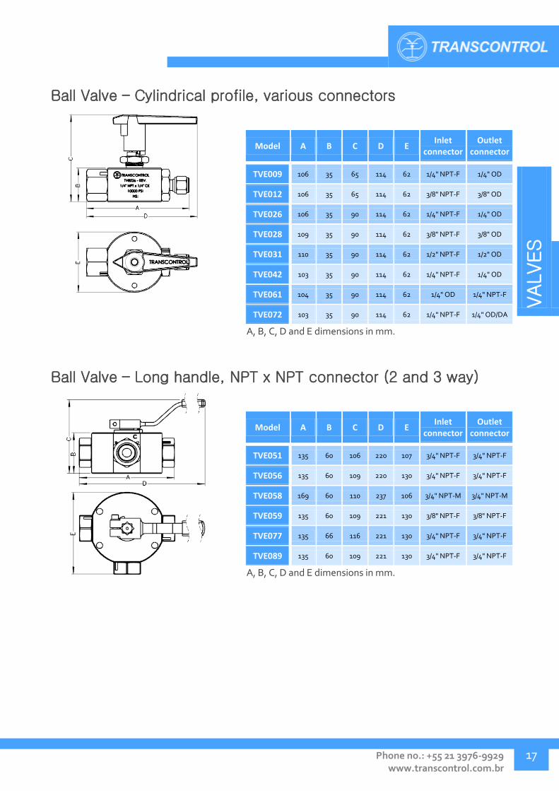
Ball Valve – Cylindrical profile, various connectors
Model A B C D E Inlet
connector Outlet
connector
TVE009 106 35 65 114 62 1/4" NPT-F 1/4" OD
TVE012 106 35 65 114 62 3/8" NPT-F 3/8" OD
TVE026 106 35 90 114 62 1/4" NPT-F 1/4" OD
TVE028 109 35 90 114 62 3/8" NPT-F 3/8" OD
TVE031 110 35 90 114 62 1/2" NPT-F 1/2" OD
TVE042 103 35 90 114 62 1/4" NPT-F 1/4" OD
TVE061 104 35 90 114 62 1/4" OD 1/4" NPT-F
TVE072 103 35 90 114 62 1/4" NPT-F 1/4" OD/DA
A, B, C, D and E dimensions in mm.
Ball Valve – Long handle, NPT x NPT connector (2 and 3 way)
Model A B C D E Inlet
connector Outlet
connector
TVE051 135 60 106 220 107 3/4" NPT-F 3/4" NPT-F
TVE056 135 60 109 220 130 3/4" NPT-F 3/4" NPT-F
TVE058 169 60 110 237 106 3/4" NPT-M 3/4" NPT-M
TVE059 135 60 109 221 130 3/8" NPT-F 3/8" NPT-F
TVE077 135 66 116 221 130 3/4" NPT-F 3/4" NPT-F
TVE089 135 60 109 221 130 3/4" NPT-F 3/4" NPT-F
A, B, C, D and E dimensions in mm.

VALVES
Transcontrol Catalog 2016 Edition – Rev. 01
VALVES
18
SUBSEA BALL VALVES - TVE
As a specialization of the TVE ball valve line, TVE Subsea valves were developed to perform rapid operations of liquid or gas flow control in systems installed in subsea environments. Indicated for use as fluid control instrumentation with actuation by R.O.V or remote torque interfaces.
Application:
Applied for flow control in liquid, gas and vapor lines in subsea systems, at a depth of up to 2500 meters.
Technical Specification:
Pressure rating: up to 15.000 PSI.
Temperature range: 4° to 65º C.
Work depth: up to 2.500 m
Connector: 1/4", 3/8", 1/2" NPT, 9/16" MP
Body materials: AISI 316, UNS S31803 duplex.
Sealing: Peek, KEL-F or PTFE.
Diameter: 1/4" to 1".
Model Work pressure
(psi) Ways /
Positions Inlet
connector Outlet
connector Body material Stem material Hydraulic diagram
TVE074 15000 3/2 3/8” NPT-F 3/8” NPT-F UNS S31803
Duplex UNS S32550 Superduplex
TVE078 10000 3/2 1/2" NPT-F 1/2" NPT-F UNS S31803
Duplex UNS S32550 Superduplex
TVE079 10000 3/2 1/4" NPT-F 1/4" NPT-F UNS S31803
Duplex UNS S32550 Superduplex
TVE080 10000 4/2 1/2" NPT-F 1/2" NPT-F UNS S31803
Duplex UNS S32550 Superduplex
TVE081 10000 3/2 1/2" NPT-F 1/2" NPT-F UNS S31803
Duplex UNS S32550 Superduplex
TVE083 10000 2/2 3/8" NPT-F 3/8" NPT-F UNS S31803
Duplex UNS S32550 Superduplex
TVE085 5000 4/2 1/4" NPT 1/4" NPT AISI 316 UNS S32550 Superduplex
TVE086 5000 3/2 3/8” NPT-F 3/8” NPT-F AISI 316 UNS S32550 Superduplex
TVE092 10000 3/2 3/8" NPT-F 3/8" NPT-F UNS S31803
Duplex UNS S32550 Superduplex
TVE094 5000 4/2 3/8" NPT-F 3/8" NPT-F AISI 316 UNS S32550 Superduplex
Tve095 10000 3/2 9/16" OD MP 9/16" OD MP UNS S31803
Duplex UNS S32550 Superduplex
TVE096 10000 4/2 9/16" MP 9/16" MP UNS S31803
Duplex UNS S32550 Superduplex
TVE097 10000 3/2 9/16" MP 9/16" MP UNS S31803
Duplex UNS S32550 Superduplex
TVE098 10000 2/2 9/16" MP 9/16" MP UNS S31803
Duplex UNS S32550 Superduplex
TVE099 10000 3/2 9/16" MP 9/16" MP UNS S31803
Duplex UNS S32550 Superduplex
TVE100 10000 2/2 1/4" NPT-F 1/4" NPT-F UNS S31803
Duplex UNS S32550 Superduplex
TVE102 10000 3/2 1/2" NPT-F 1/2" NPT-F UNS S31803
Duplex UNS S32550 Superduplex
VALVES
Tel.: +55 21 3976-9929 www.transcontrol.com.br
19
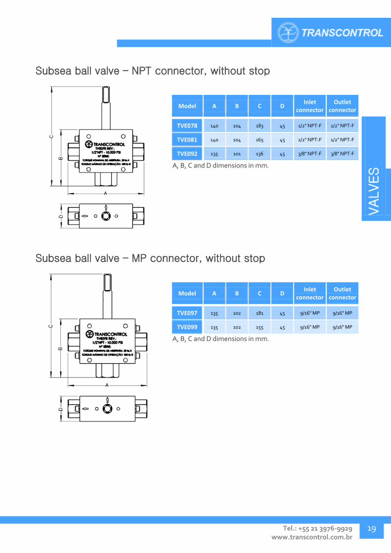
Subsea ball valve – NPT connector, without stop
Model A B C D Inlet
connector Outlet
connector
TVE078 140 104 183 45 1/2" NPT-F 1/2" NPT-F
TVE081 140 104 165 45 1/2" NPT-F 1/2" NPT-F
TVE092 135 101 136 45 3/8" NPT-F 3/8" NPT-F
A, B, C and D dimensions in mm.
Subsea ball valve – MP connector, without stop
Model A B C D Inlet
connector Outlet
connector
TVE097 135 102 181 45 9/16" MP 9/16" MP
TVE099 135 102 155 45 9/16" MP 9/16" MP
A, B, C and D dimensions in mm.
VALVES
Transcontrol Catalog 2016 Edition – Rev. 01
VALVES
20
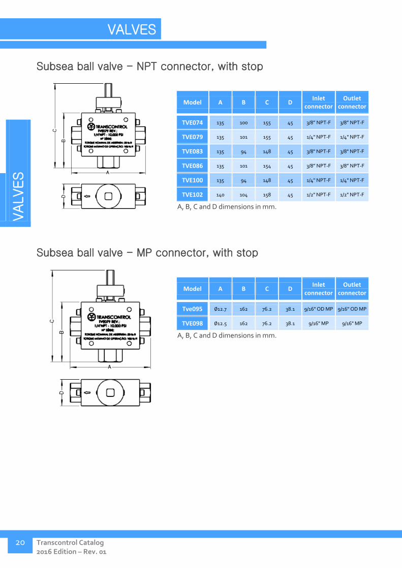
Subsea ball valve - NPT connector, with stop
Model A B C D Inlet
connector Outlet
connector
TVE074 135 100 155 45 3/8” NPT-F 3/8” NPT-F
TVE079 135 101 155 45 1/4" NPT-F 1/4" NPT-F
TVE083 135 94 148 45 3/8" NPT-F 3/8" NPT-F
TVE086 135 101 154 45 3/8” NPT-F 3/8” NPT-F
TVE100 135 94 148 45 1/4" NPT-F 1/4" NPT-F
TVE102 140 104 158 45 1/2" NPT-F 1/2" NPT-F
A, B, C and D dimensions in mm.
Subsea ball valve - MP connector, with stop
Model A B C D Inlet
connector Outlet
connector
Tve095 ∅12.7 162 76.2 38.1 9/16" OD MP 9/16" OD MP
TVE098 ∅12.5 162 76.2 38.1 9/16" MP 9/16" MP
A, B, C and D dimensions in mm.

VALVES
Tel.: +55 21 3976-9929 www.transcontrol.com.br
21
Subsea ball valve - NPT connector, 4 way
Model A B C D Inlet
connector Outlet
connector
TVE080 154 89 161 154 1/2" NPT-F 1/2" NPT-F
TVE085 148 89 161 148 1/4" NPT-F 1/4" NPT-F
TVE094 148 89 161 148 3/8" NPT-F 3/8" NPT-F
A, B, C and D dimensions in mm.
Subsea ball valve - MP connector, 4 way
Model A B C D Inlet
connector Outlet
connector
TVE096 154 89 161 154 9/16" MP 9/16" MP
A, B, C and D dimensions in mm.

VALVES
Transcontrol Catalog 2016 Edition – Rev. 01
VALVES
22
NEEDLE VALVES – TVB
Needle block valves are largely employed in hydraulic systems, where reliability and a smooth flow control operation are required. TVB valves manufactured by Transcontrol are available in an ample combination of types and configurations of connections and stems, providing flexibility to better fulfill project requirements.
Application:
Recommended in cases where there is a necessity of fine flow regulation and/or complete flow blocking.
Technical Specification:
Pressure rating: up to 10.000 Psi
Temperature range: 4° to 65ºC
Connectors: Threaded (NPT, API LP), Tubing ferrule (OD), Hi-seal (OD), SW (welded).
Stem type: Rotary, non rotary, long
Diameter: 1/4, 3/8, 1/2, 3/4, and 1".
Configurations: Straight or angled
Body materials: ASTM A351 Gr CF8M cast stainless, AISI 316, carbon steel (contact for others).
Sealing type: Metal-Metal
Model Work pressure
(psi) Inlet connector Outlet connector Body material Stem material
TVB015 6500 3/8” HI-SEAL 3/8” HI-SEAL ASTM A351 Gr CF8M AISI 316
TVB016 6500 1/2" NPT-M 1/2" NPT-F ASTM A351 Gr CF8M AISI 316
TVB017 6500 1/2" NPT - F 1/2" NPT-F ASTM A351 Gr CF8M AISI 316
TVB018 6500 1/2" NPT - M 1/2" NPT - F ASTM A216 GR WCB AISI 316
TVB019 6500 1/4" NPT - F 1/4" NPT - F ASTM A351 Gr CF8M AISI 316
TVB020 6500 1/4" HI-SEAL 1/4" HI-SEAL ASTM A351 Gr CF8M ASTM A564 TP 630 17-4PH
TVB021 6500 3/8” HI-SEA 3/8” HI-SEA ASTM A351 Gr CF8M ASTM A564 TP 630 17-4PH
TVB022 6500 1/2" HI-SEAL 1/2" HI-SEAL ASTM A351 Gr CF8M ASTM A564 TP 630 17-4PH
TVB023 6500 1/2" HI-SEAL 1/2" HI-SEAL ASTM A351 Gr CF8M AISI 316
TVB024 6000 1/4" OD 1/4" OD AISI 316 AISI 316
TVB025 6000 3/8” OD 3/8” OD AISI 316 AISI 316
TVB048 6500 1/4" NPT - M 1/4" NPT - F ASTM A351 Gr CF8M AISI 316
TVB049 6500 3/8" NPT - F 3/8" NPT - F ASTM A351 Gr CF8M AISI 316
TVB050 6500 1/2" NPT - M 1/2" NPT - M ASTM A351 Gr CF8M AISI 316
TVB051 6500 1/2" NPT - M 1/2" NPT - F ASTM A351 Gr CF8M ASTM A564 TP 630 17-4PH
TVB052 6500 1/2" API-LP -M 1/2" API-LP - F ASTM A351 Gr CF8M ASTM A564 TP 630 17-4PH

VALVES
Tel.: +55 21 3976-9929 www.transcontrol.com.br
23
Model Work pressure
(psi) Inlet connector Outlet connector Body material Stem material
TVB053 6500 1/2" NPT - F 10 mm HI-SEAL ASTM A351 Gr CF8M ASTM A564 TP 630 17-4PH
TVB054 6500 1/2" API-LP 1/2" API-LP ASTM A351 Gr CF8M ASTM A564 TP 630 17-4PH
TVB055 5000 3/4" SW 3/4" SW AISI 316 ASTM A564 TP 630 17-4PH
TVB056 5000 1/2" SW 1/2" SW ASTM A351 Gr CF8 ASTM A564 TP 630 17-4PH
TVB057 5000 1/2" SW 1/2" SW ASTM A36 ASTM A564 TP 630 17-4PH
TVB058 6500 1/4" OD 1/4" OD AISI 316 AISI 316
TVB059 6500 1/2" NPT - F 1/2" NPT - F ASTM A351 Gr CF8M ASTM A564 TP 630 17-4PH
TVB060 6500 1/4" NPT - F 1/4" NPT - F ASTM A351 Gr CF8M AISI 316
TVB061 5000 1/2" SW 1/2" SW ASTM A36 ASTM A564 TP 630 17-4PH
TVB062 5000 1/4" NPT -M 1/4" NPT -M AISI 316 AISI 316
TVB063 5000 1/2" SW 1/2" SW ASTM A351 Gr CF8 AISI 316 / Stellite
TVB064 6000 3/8” OD 3/8” OD AISI 316 AISI 316
TVB065 6500 3/8" NPT - F 3/8" NPT - F ASTM A351 Gr CF8M ASTM A564 TP 630 17-4PH
TVB066 5000 1/2” API/LP 1/2” API/LP ASTM A36 ASTM A564 TP 630
TVB067 5000 1/4" NPT -M 1/4" NPT -M AISI 316 AISI 316
TVB068 5000 1/2" NPT - F 1/2" NPT - F AISI 1020 ASTM A564 TP 630 17-4PH
TVB069 5000 1/4" NPT -F 1/4" NPT -F AISI 316 AISI 316
TVB070 6500 1/2" NPT - F 1/2" NPT - F AISI 1020 AISI 316
TVB071 5000 3/4" SW 3/4" SW ASTM A36 ASTM A564 TP 630 17-4PH
TVB072 6500 1/4" HI-SEAL 1/4" HI-SEAL ASTM A351 Gr CF8M AISI 316
TVB072 6500 1/4" HI-SEAL 1/4" HI-SEAL ASTM A351 Gr CF8M AISI 316
TVB073 5000 1/2" NPT -F 1/2" NPT -F AISI 316 AISI 316
TVB074 6500 3/4" SW 3/4" SW AISI 316 ASTM A564 TP 630 17-4PH
TVB075 6500 1/2" NPT - M 1/2" NPT - F ASTM A216 GR WCB ASTM A564 TP 630 17-4PH
TVB076 6500 3/4" SW 3/4" SW AISI 316 AISI 316
TVB077 3000 1/2" NPT -M 1/2" NPT -F ASTM A105 ASTM A564 tp 630
TVB078 6500 1/4" OD 1/4" OD AISI 316 ASTM A564 TP 630
TVB079 5000 1/2" SW 1/2" SW ASTM A105 ASTM A564 TP 630 17-4PH
TVB080 3000 1/2" NPT - M 1/2" NPT - F ASTM A105 ASTM A564 TP 630 17-4PH
TVB081 5000 3/4" SW 3/4" SW ASTM A105 ASTM A564 TP 630
TVB082 3000 1" SW 1" SW AISI 316 AISI 316
TVB083 6500 1/2" NPT - F 1/2" NPT - F ASTM A351 Gr CF8M AISI 316
TVB084 3000 1" SW 1" SW ASTM A105 ASTM A564 TP 630
VALVES
Transcontrol Catalog 2016 Edition – Rev. 01
VALVES
24
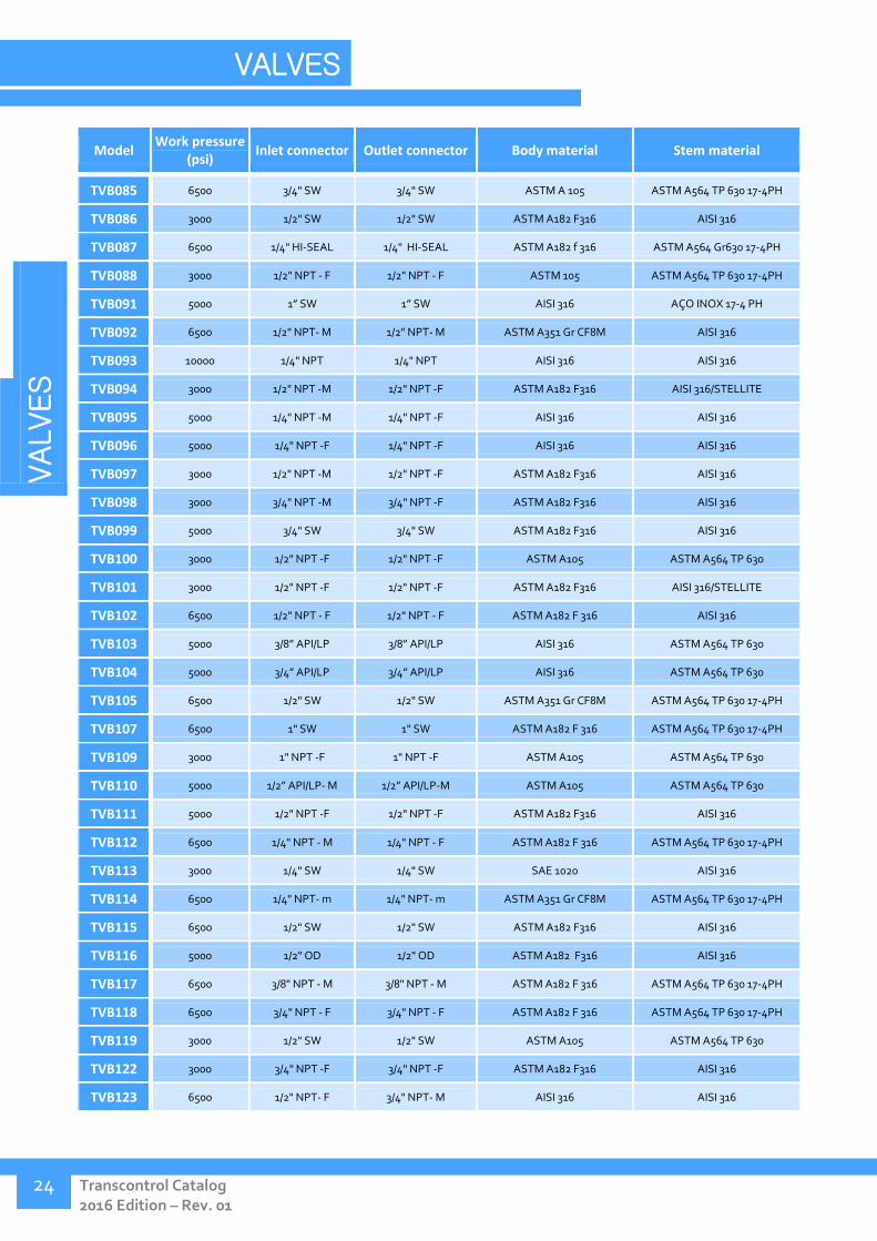
Model Work pressure
(psi) Inlet connector Outlet connector Body material Stem material
TVB085 6500 3/4" SW 3/4" SW ASTM A 105 ASTM A564 TP 630 17-4PH
TVB086 3000 1/2" SW 1/2" SW ASTM A182 F316 AISI 316
TVB087 6500 1/4" HI-SEAL 1/4" HI-SEAL ASTM A182 f 316 ASTM A564 Gr630 17-4PH
TVB088 3000 1/2" NPT - F 1/2" NPT - F ASTM 105 ASTM A564 TP 630 17-4PH
TVB091 5000 1” SW 1” SW AISI 316 AÇO INOX 17-4 PH
TVB092 6500 1/2" NPT- M 1/2" NPT- M ASTM A351 Gr CF8M AISI 316
TVB093 10000 1/4" NPT 1/4" NPT AISI 316 AISI 316
TVB094 3000 1/2" NPT -M 1/2" NPT -F ASTM A182 F316 AISI 316/STELLITE
TVB095 5000 1/4" NPT -M 1/4" NPT -F AISI 316 AISI 316
TVB096 5000 1/4" NPT -F 1/4" NPT -F AISI 316 AISI 316
TVB097 3000 1/2" NPT -M 1/2" NPT -F ASTM A182 F316 AISI 316
TVB098 3000 3/4" NPT -M 3/4" NPT -F ASTM A182 F316 AISI 316
TVB099 5000 3/4" SW 3/4" SW ASTM A182 F316 AISI 316
TVB100 3000 1/2" NPT -F 1/2" NPT -F ASTM A105 ASTM A564 TP 630
TVB101 3000 1/2" NPT -F 1/2" NPT -F ASTM A182 F316 AISI 316/STELLITE
TVB102 6500 1/2" NPT - F 1/2" NPT - F ASTM A182 F 316 AISI 316
TVB103 5000 3/8” API/LP 3/8” API/LP AISI 316 ASTM A564 TP 630
TVB104 5000 3/4” API/LP 3/4” API/LP AISI 316 ASTM A564 TP 630
TVB105 6500 1/2" SW 1/2" SW ASTM A351 Gr CF8M ASTM A564 TP 630 17-4PH
TVB107 6500 1" SW 1" SW ASTM A182 F 316 ASTM A564 TP 630 17-4PH
TVB109 3000 1" NPT -F 1" NPT -F ASTM A105 ASTM A564 TP 630
TVB110 5000 1/2” API/LP- M 1/2” API/LP-M ASTM A105 ASTM A564 TP 630
TVB111 5000 1/2" NPT -F 1/2" NPT -F ASTM A182 F316 AISI 316
TVB112 6500 1/4" NPT - M 1/4" NPT - F ASTM A182 F 316 ASTM A564 TP 630 17-4PH
TVB113 3000 1/4" SW 1/4" SW SAE 1020 AISI 316
TVB114 6500 1/4" NPT- m 1/4" NPT- m ASTM A351 Gr CF8M ASTM A564 TP 630 17-4PH
TVB115 6500 1/2" SW 1/2" SW ASTM A182 F316 AISI 316
TVB116 5000 1/2" OD 1/2" OD ASTM A182 F316 AISI 316
TVB117 6500 3/8" NPT - M 3/8" NPT - M ASTM A182 F 316 ASTM A564 TP 630 17-4PH
TVB118 6500 3/4" NPT - F 3/4" NPT - F ASTM A182 F 316 ASTM A564 TP 630 17-4PH
TVB119 3000 1/2" SW 1/2" SW ASTM A105 ASTM A564 TP 630
TVB122 3000 3/4" NPT -F 3/4" NPT -F ASTM A182 F316 AISI 316
TVB123 6500 1/2" NPT- F 3/4" NPT- M AISI 316 AISI 316
VALVES
Tel.: +55 21 3976-9929 www.transcontrol.com.br
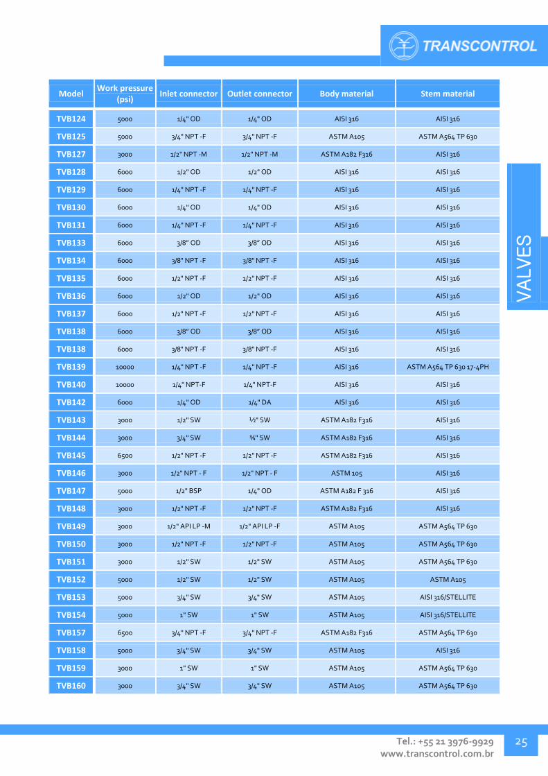
25
Model Work pressure
(psi) Inlet connector Outlet connector Body material Stem material
TVB124 5000 1/4" OD 1/4" OD AISI 316 AISI 316
TVB125 5000 3/4" NPT -F 3/4" NPT -F ASTM A105 ASTM A564 TP 630
TVB127 3000 1/2" NPT -M 1/2" NPT -M ASTM A182 F316 AISI 316
TVB128 6000 1/2" OD 1/2" OD AISI 316 AISI 316
TVB129 6000 1/4" NPT -F 1/4" NPT -F AISI 316 AISI 316
TVB130 6000 1/4" OD 1/4" OD AISI 316 AISI 316
TVB131 6000 1/4" NPT -F 1/4" NPT -F AISI 316 AISI 316
TVB133 6000 3/8” OD 3/8” OD AISI 316 AISI 316
TVB134 6000 3/8" NPT -F 3/8" NPT -F AISI 316 AISI 316
TVB135 6000 1/2" NPT -F 1/2" NPT -F AISI 316 AISI 316
TVB136 6000 1/2" OD 1/2" OD AISI 316 AISI 316
TVB137 6000 1/2" NPT -F 1/2" NPT -F AISI 316 AISI 316
TVB138 6000 3/8” OD 3/8” OD AISI 316 AISI 316
TVB138 6000 3/8" NPT -F 3/8" NPT -F AISI 316 AISI 316
TVB139 10000 1/4" NPT -F 1/4" NPT -F AISI 316 ASTM A564 TP 630 17-4PH
TVB140 10000 1/4" NPT-F 1/4" NPT-F AISI 316 AISI 316
TVB142 6000 1/4" OD 1/4" DA AISI 316 AISI 316
TVB143 3000 1/2" SW ½" SW ASTM A182 F316 AISI 316
TVB144 3000 3/4" SW ¾" SW ASTM A182 F316 AISI 316
TVB145 6500 1/2" NPT -F 1/2" NPT -F ASTM A182 F316 AISI 316
TVB146 3000 1/2" NPT - F 1/2" NPT - F ASTM 105 AISI 316
TVB147 5000 1/2" BSP 1/4" OD ASTM A182 F 316 AISI 316
TVB148 3000 1/2" NPT -F 1/2" NPT -F ASTM A182 F316 AISI 316
TVB149 3000 1/2" API LP -M 1/2" API LP -F ASTM A105 ASTM A564 TP 630
TVB150 3000 1/2" NPT -F 1/2" NPT -F ASTM A105 ASTM A564 TP 630
TVB151 3000 1/2" SW 1/2" SW ASTM A105 ASTM A564 TP 630
TVB152 5000 1/2" SW 1/2" SW ASTM A105 ASTM A105
TVB153 5000 3/4" SW 3/4" SW ASTM A105 AISI 316/STELLITE
TVB154 5000 1" SW 1" SW ASTM A105 AISI 316/STELLITE
TVB157 6500 3/4" NPT -F 3/4" NPT -F ASTM A182 F316 ASTM A564 TP 630
TVB158 5000 3/4" SW 3/4" SW ASTM A105 AISI 316
TVB159 3000 1" SW 1" SW ASTM A105 ASTM A564 TP 630
TVB160 3000 3/4" SW 3/4" SW ASTM A105 ASTM A564 TP 630

VALVES
Transcontrol Catalog 2016 Edition – Rev. 01
VALVES
26
Model Work pressure
(psi) Inlet connector Outlet connector Body material Stem material
TVB161 3000 1/2" NPT -F 1/2" NPT -F ASTM A182 F316 AISI 316/STELLITE
TVB162 6000 1/4" NPT -M 1/4" NPT -F AISI 316 AISI 316
TVB163 6500 1/2" NPT -F 1/2" NPT -F ASTM A182 F316 AISI 316
TVB164 6500 1/2" OD 1/2" NPT ASTM A182 F316 AISI 316
TVB165 3000 1/2" OD 1/2" NPT ASTM A105 ASTM A564 TP 630
TVB166 5000 1" NPT -F 1" NPT -F ASTM A182 F316 AISI 316
TVB167 5000 3/4" SW 3/4" SW ASTM A182 F316 AISI 316
TVB168 5000 1/8” OD 1/8” OD AISI 316 AISI 316
TVB169 5000 1/4" NPT- F 1/4" NPT- F ASTM A351 Gr CF8M AISI 316
TVB170 3000 1/4" NPT -M 1/4" NPT -M ASTM A351 Gr CF8m AISI 316
TVB171 3000 1/2" NPT -F 1/2" NPT -F ASTM A105 ASTM A564 TP 630
TVB174 6000 1/2" SW 1/2" SW ASTM A105 ASTM A564 TP 630
TVB175 6000 1/2" OD 1/2" DA ASTM A351 Gr CF8m AISI 316
TVB176 5000 1" SW 1" SW ASTM A105 ASTM A564 TP 630 17-4 PH
TVB177 3000 1" NPT -F 1" NPT -F AISI 304 AISI 304 C/ STELLITE
Didn't find what you were looking for?
Contact Transcontrol. We develop projects and solutions according to your specifications.

VALVES
Tel.: +55 21 3976-9929 www.transcontrol.com.br
27
Needle valve – Inline cast, OD x OD connector, non rotary stem
Model A B C D Inlet
connector Outlet
connector
TVB015 110 86.2 110 15.3 3/8” HI-SEAL 3/8” HI-SEAL
TVB020 110 86.2 102 15.3 1/4" HI-SEAL 1/4" HI-SEAL
TVB021 110 86.2 110 15.3 3/8” HI-SEA 3/8” HI-SEA
TVB022 110 86.2 117 15.3 1/2" HI-SEAL 1/2" HI-SEAL
TVB023 110 86.2 117 15.3 1/2" HI-SEAL 1/2" HI-SEAL
TVB072 110 86.2 102 15.3 1/4" HI-SEAL 1/4" HI-SEAL
TVB087 110 86.2 94 20 1/4" HI-SEAL 1/4" HI-SEAL
A, B, C, D and F dimensions in mm.
Needle valve – Inline cast, NPT x NPT connector, non rotary stem
Model A B C D Inlet
connector Outlet
connector
TVB017 110 86.2 88 15.3 1/2"
NPT - F 1/2"
NPT - F
TVB018 110 86.2 88 15.3 1/2"
NPT - M 1/2"
NPT - F
TVB019 110 86.2 88 15.3 1/4"
NPT - F 1/4"
NPT - F
TVB048 110 86.2 88 15.3 1/4"
NPT - M 1/4"
NPT - F
TVB049 110 86.2 88 15.3 3/8"
NPT - F 3/8"
NPT - F
TVB050 110 86.2 88 15.3 1/2"
NPT - M 1/2"
NPT - M
TVB051 110 86.2 88 15.3 1/2"
NPT - M 1/2"
NPT - F
TVB059 110 86.2 88 15.3 1/2"
NPT - F 1/2"
NPT - F
TVB060 110 86.2 88 15.3 1/4"
NPT - F 1/4"
NPT - F
TVB065 110 86.2 88 15.3 3/8"
NPT - F 3/8"
NPT - F
TVB068 110 84.2 88 17.5 1/2"
NPT-F 1/2"
NPT - F
TVB070 110 84.2 88 17.5 1/2"
NPT - F 1/2"
NPT - F
Continues next page. A, B, C and D dimensions in mm.
VALVES
Transcontrol Catalog 2016 Edition – Rev. 01
VALVES
28
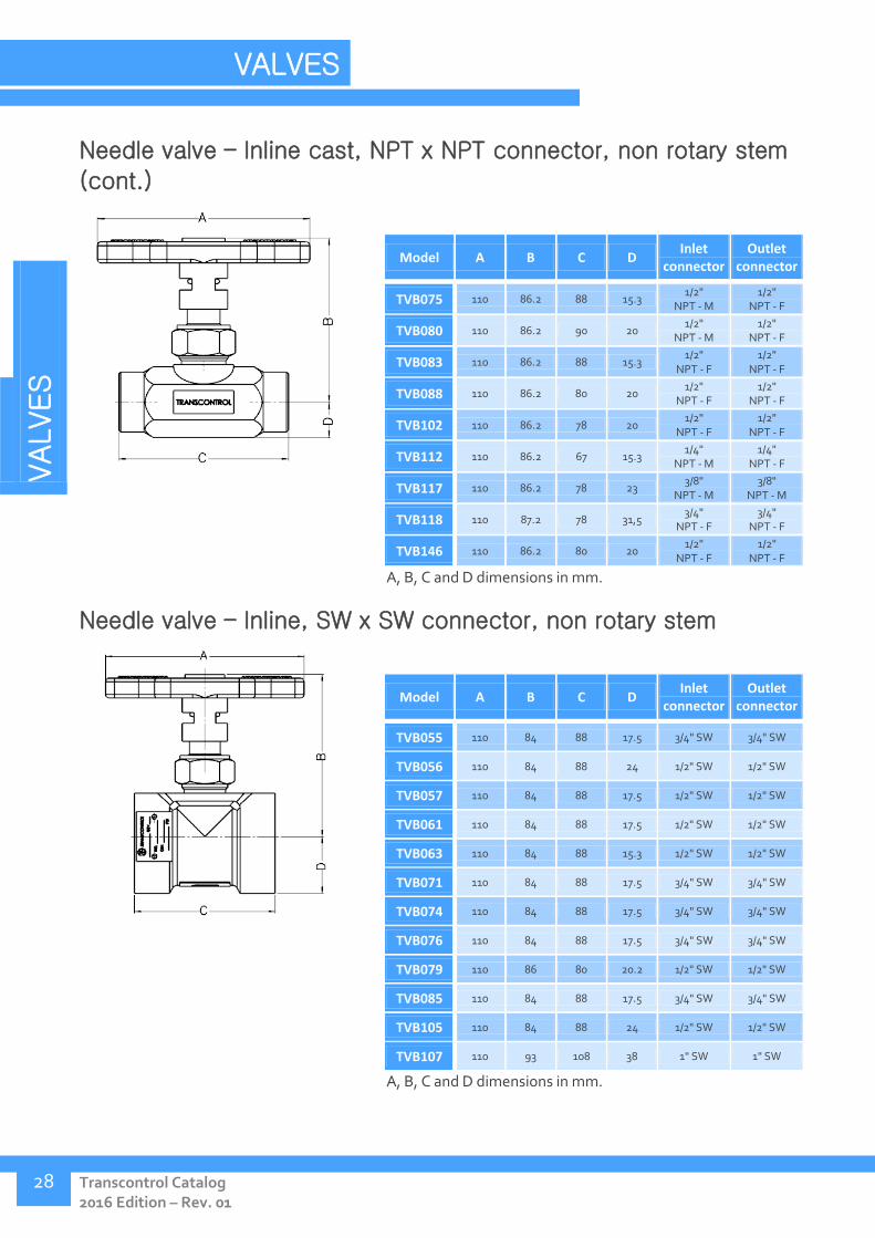
Needle valve – Inline cast, NPT x NPT connector, non rotary stem
(cont.)
Model A B C D Inlet
connector Outlet
connector
TVB075 110 86.2 88 15.3 1/2"
NPT - M 1/2"
NPT - F
TVB080 110 86.2 90 20 1/2"
NPT - M 1/2"
NPT - F
TVB083 110 86.2 88 15.3 1/2"
NPT - F 1/2"
NPT - F
TVB088 110 86.2 80 20 1/2"
NPT - F 1/2"
NPT - F
TVB102 110 86.2 78 20 1/2"
NPT - F 1/2"
NPT - F
TVB112 110 86.2 67 15.3 1/4"
NPT - M 1/4"
NPT - F
TVB117 110 86.2 78 23 3/8"
NPT - M 3/8"
NPT - M
TVB118 110 87.2 78 31,5 3/4"
NPT - F 3/4"
NPT - F
TVB146 110 86.2 80 20 1/2"
NPT - F 1/2"
NPT - F
A, B, C and D dimensions in mm.
Needle valve – Inline, SW x SW connector, non rotary stem
Model A B C D Inlet
connector Outlet
connector
TVB055 110 84 88 17.5 3/4" SW 3/4" SW
TVB056 110 84 88 24 1/2" SW 1/2" SW
TVB057 110 84 88 17.5 1/2" SW 1/2" SW
TVB061 110 84 88 17.5 1/2" SW 1/2" SW
TVB063 110 84 88 15.3 1/2" SW 1/2" SW
TVB071 110 84 88 17.5 3/4" SW 3/4" SW
TVB074 110 84 88 17.5 3/4" SW 3/4" SW
TVB076 110 84 88 17.5 3/4" SW 3/4" SW
TVB079 110 86 80 20.2 1/2" SW 1/2" SW
TVB085 110 84 88 17.5 3/4" SW 3/4" SW
TVB105 110 84 88 24 1/2" SW 1/2" SW
TVB107 110 93 108 38 1" SW 1" SW
A, B, C and D dimensions in mm.

VALVES
Tel.: +55 21 3976-9929 www.transcontrol.com.br
29
Needle valve – Inline, NPT x OD connector, non rotary stem
Model A B C D Inlet
connector Outlet
connector
TVB053 110 90 65,4 24 1/2"
NPT - F 10mm HI-
SEAL
A, B, C and D dimensions in mm.
Needle valve – Inline, API-LP x API-LP connector, non rotary
stem
Model A B C D Inlet
connector Outlet
connector
TVB054 110 90 79 24 1/2"
API-LP-F 1/2"
API-LP-M
A, B, C and D dimensions in mm.
Needle valve – Angled, NPT x NPT connector, non rotary stem
Model A B C D Inlet
connector Outlet
connector
TVB016 110 90 35 46 1/2"
NPT-M 1/2"
NPT-F
A, B, C and D dimensions in mm.

VALVES
Transcontrol Catalog 2016 Edition – Rev. 01
VALVES
30
Needle valve – Angled, API-LP x API-LP connector, non rotary
stem
Model A B C D Inlet
connector Outlet
connector
TVB052 110 90 35 46 1/2"
API-LP-M 1/2"
API-LP-F
A, B, C and D dimensions in mm.
Needle valve – Angled, BSP x OD connector, non rotary stem
Model A B C D Inlet
connector Outlet
connector
TVB147 110 85,7 65 33 1/2" BSP 1/4" OD
A, B, C and D dimensions in mm.
Needle valve – Inline, NPT x NPT connector, non rotary long stem
Model A B C D Inlet
connector Outlet
connector
TVB092 110 203 88 18,4 1/2"
NPT- M 1/2"
NPT- M
TVB114 110 203 88 18,4 1/4"
NPT-M 1/4"
NPT-M
TVB123 110 203 65 21,5 1/2"
NPT- F 3/4"
NPT- M
TVB169 110 200 88 15.3 1/4"
NPT-F 1/4"
NPT-F
A, B, C and D dimensions in mm.
VALVES
Tel.: +55 21 3976-9929 www.transcontrol.com.br
31
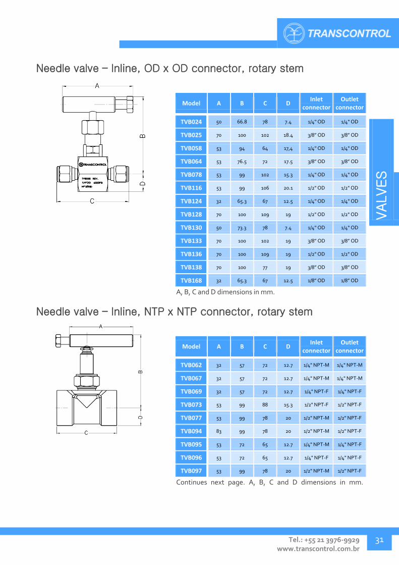
Needle valve – Inline, OD x OD connector, rotary stem
Model A B C D Inlet
connector Outlet
connector
TVB024 50 66.8 78 7.4 1/4" OD 1/4" OD
TVB025 70 100 102 18.4 3/8” OD 3/8” OD
TVB058 53 94 64 17,4 1/4" OD 1/4" OD
TVB064 53 76.5 72 17.5 3/8” OD 3/8” OD
TVB078 53 99 102 15.3 1/4" OD 1/4" OD
TVB116 53 99 106 20.1 1/2" OD 1/2" OD
TVB124 32 65.3 67 12.5 1/4" OD 1/4" OD
TVB128 70 100 109 19 1/2" OD 1/2" OD
TVB130 50 73.3 78 7.4 1/4" OD 1/4" OD
TVB133 70 100 102 19 3/8” OD 3/8” OD
TVB136 70 100 109 19 1/2" OD 1/2" OD
TVB138 70 100 77 19 3/8” OD 3/8” OD
TVB168 32 65.3 67 12.5 1/8” OD 1/8” OD
A, B, C and D dimensions in mm.
Needle valve – Inline, NTP x NTP connector, rotary stem
Model A B C D Inlet
connector Outlet
connector
TVB062 32 57 72 12.7 1/4" NPT-M 1/4" NPT-M
TVB067 32 57 72 12.7 1/4" NPT-M 1/4" NPT-M
TVB069 32 57 72 12.7 1/4" NPT-F 1/4" NPT-F
TVB073 53 99 88 15.3 1/2" NPT-F 1/2" NPT-F
TVB077 53 99 78 20 1/2" NPT-M 1/2" NPT-F
TVB094 83 99 78 20 1/2" NPT-M 1/2" NPT-F
TVB095 53 72 65 12.7 1/4" NPT-M 1/4" NPT-F
TVB096 53 72 65 12.7 1/4" NPT-F 1/4" NPT-F
TVB097 53 99 78 20 1/2" NPT-M 1/2" NPT-F
Continues next page. A, B, C and D dimensions in mm.

VALVES
Transcontrol Catalog 2016 Edition – Rev. 01
VALVES
32
Needle valve – Inline, NTP x NTP connector, rotary stem (cont.)
Model A B C D Inlet
connector Outlet
connector
TVB098 53 99 78 20 3/4" NPT-M 3/4" NPT-F
TVB100 53 99 78 20 1/2" NPT-F 1/2" NPT-F
TVB101 53 99 78 20 1/2" NPT-F 1/2" NPT-F
TVB109 120 140 102 23 1" NPT-F 1" NPT-F
TVB111 53 99 78 20 1/2" NPT-F 1/2" NPT-F
TVB122 120 140 102 23 3/4" NPT-F 3/4" NPT -F
TVB125 53 99 78 20.5 3/4" NPT-F 3/4" NPT–F
TVB127 53 99 78 20 1/2" NPT-M 1/2" NPT-M
TVB129 50 70 54 10 1/4" NPT-F 1/4" NPT-F
TVB131 50 70 54 10 1/4" NPT-F 1/4" NPT-F
TVB134 70 100 77 19 3/8" NPT-F 3/8" NPT-F
TVB135 70 100 77 19 1/2" NPT-F 1/2" NPT-F
TVB137 70 100 77 19 1/2" NPT-F 1/2" NPT-F
TVB138 70 100 77 19 3/8" NPT-F 3/8" NPT-F
TVB139 50 64.9 43 26 1/4" NPT-F 1/4" NPT-F
TVB145 53 99 78 20.2 1/2" NPT-F 1/2" NPT-F
TVB148 53 99 78 20 1/2" NPT-F 1/2" NPT-F
TVB150 53 99 78 20 1/2" NPT-F 1/2" NPT-F
TVB157 53 126 78 21 3/4" NPT-F 3/4" NPT-F
TVB161 53 99 78 20 1/2" NPT-F 1/2" NPT-F
TVB162 50 70 59 10 1/4" NPT-M 1/4" NPT-F
TVB163 53 99 78 20.2 1/2" NPT-F 1/2" NPT-F
TVB166 220 140 102 23 1" NPT-F 1" NPT-F
TVB170 50 70 64 10 1/4" NPT-M 1/4" NPT-M
TVB171 53 99 78 20 1/2" NPT-F 1/2" NPT-F
TVB177 220 140 113 23.5 1" NPT-F 1" NPT -F
A, B, C and D dimensions in mm.

VALVES
Tel.: +55 21 3976-9929 www.transcontrol.com.br
33
Needle valve – Inline, SW x SW connector, rotary stem
Model A B C D Inlet
connector Outlet
connector
TVB081 53 99 78 20 3/4" SW 3/4" SW
TVB082 53 140 102 23 1" SW 1" SW
TVB084 53 140 102 23 1" SW 1" SW
TVB086 53 99 80 23 1/2" SW 1/2" SW
TVB099 53 99 80 20 3/4" SW 3/4" SW
TVB113 53 72 65 13 1/4" SW 1/4" SW
TVB115 53 99 80 20.3 1/2" SW 1/2" SW
TVB119 53 99 78 20.2 1/2" SW 1/2" SW
TVB151 53 99 78 20.2 1/2" SW 1/2" SW
TVB152 83 99 78 20 1/2" SW 1/2" SW
TVB153 83 99 78 20 3/4" SW 3/4" SW
TVB154 220 139 101 23 1" SW 1" SW
TVB158 53 99 78 20 3/4" SW 3/4" SW
TVB159 53 174 101 23 1" SW 1" SW
TVB160 53 99 78 20 3/4" SW 3/4" SW
TVB167 53 124 80 20 3/4" SW 3/4" SW
TVB174 83 99 78 20 1/2" SW 1/2" SW
TVB176 220 140 102 23 1" SW 1" SW
A, B, C and D dimensions in mm.
Needle valve – Inline, various connectors, rotary stem
Model A B C D Inlet
connector Outlet
connector
TVB142 53 73.3 78 7.4 1/4" OD 1/4" DA
TVB149 53 99 78 20 1/2"
API LP-M 1/2"
API LP-F
TVB164 53 92 92 20 1/2" OD 1/2"
NPT-F
TVB165 53 99 92 20 1/2" OD 1/2"
NPT-F
TVB175 53 100 109 19 1/2" OD 1/2" DA
A, B, C and D dimensions in mm.
VALVES
Transcontrol Catalog 2016 Edition – Rev. 01
VALVES
34
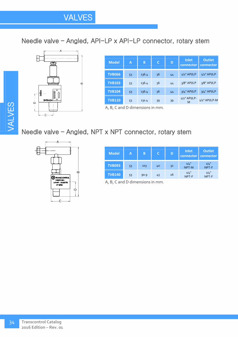
Needle valve – Angled, API-LP x API-LP connector, rotary stem
Model A B C D Inlet
connector Outlet
connector
TVB066 53 136.4 36 44 1/2” API/LP 1/2” API/LP
TVB103 53 136.4 36 44 3/8” API/LP 3/8” API/LP
TVB104 53 136.4 36 44 3/4” API/LP 3/4” API/LP
TVB110 53 131.4 39 39 1/2” API/LP-
M 1/2” API/LP-M
A, B, C and D dimensions in mm.
Needle valve – Angled, NPT x NPT connector, rotary stem
Model A B C D Inlet
connector Outlet
connector
TVB093 53 103 40 31 1/4"
NPT-M 1/4"
NPT-F
TVB140 53 90.9 43 26 1/4"
NPT-F 1/4"
NPT-F
A, B, C and D dimensions in mm.

VALVES
Tel.: +55 21 3976-9929 www.transcontrol.com.br
35
Needle valve – Inline, SW x SW connector, rotary long stem
Model A B C D Inlet
connector Outlet
connector
TVB143 53 124 80 20 1/2" SW 1/2" SW
TVB144 53 124 80 20 3/4" SW 3/4" SW
A, B, C and D dimensions in mm.
Needle valve – Flanged, SW x SW connector, rotary stem
Model A B C D Inlet
connector Outlet
connector
TVB091 250 235 120 25,5 1” SW 1” SW
A, B, C and D dimensions in mm.
VALVES
Transcontrol Catalog 2016 Edition – Rev. 01
VALVES
36
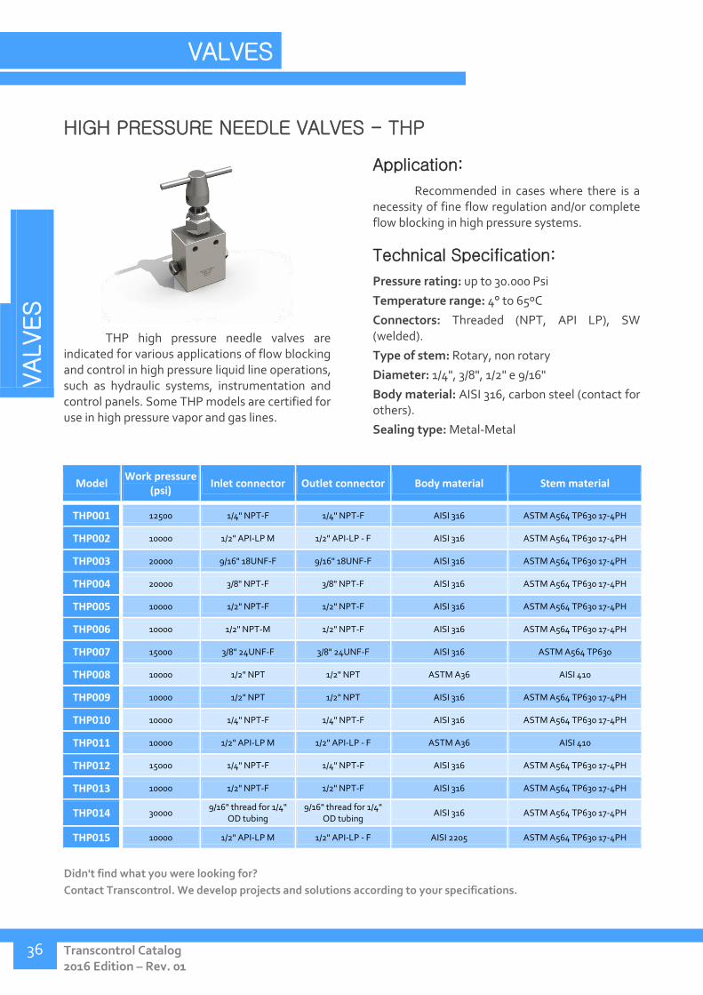
HIGH PRESSURE NEEDLE VALVES - THP
THP high pressure needle valves are indicated for various applications of flow blocking and control in high pressure liquid line operations, such as hydraulic systems, instrumentation and control panels. Some THP models are certified for use in high pressure vapor and gas lines.
Application:
Recommended in cases where there is a necessity of fine flow regulation and/or complete flow blocking in high pressure systems.
Technical Specification:
Pressure rating: up to 30.000 Psi
Temperature range: 4° to 65ºC
Connectors: Threaded (NPT, API LP), SW (welded).
Type of stem: Rotary, non rotary
Diameter: 1/4", 3/8", 1/2" e 9/16"
Body material: AISI 316, carbon steel (contact for others).
Sealing type: Metal-Metal
Model Work pressure
(psi) Inlet connector Outlet connector Body material Stem material
THP001 12500 1/4" NPT-F 1/4" NPT-F AISI 316 ASTM A564 TP630 17-4PH
THP002 10000 1/2" API-LP M 1/2" API-LP - F AISI 316 ASTM A564 TP630 17-4PH
THP003 20000 9/16" 18UNF-F 9/16" 18UNF-F AISI 316 ASTM A564 TP630 17-4PH
THP004 20000 3/8" NPT-F 3/8" NPT-F AISI 316 ASTM A564 TP630 17-4PH
THP005 10000 1/2" NPT-F 1/2" NPT-F AISI 316 ASTM A564 TP630 17-4PH
THP006 10000 1/2" NPT-M 1/2" NPT-F AISI 316 ASTM A564 TP630 17-4PH
THP007 15000 3/8" 24UNF-F 3/8" 24UNF-F AISI 316 ASTM A564 TP630
THP008 10000 1/2" NPT 1/2" NPT ASTM A36 AISI 410
THP009 10000 1/2" NPT 1/2" NPT AISI 316 ASTM A564 TP630 17-4PH
THP010 10000 1/4" NPT-F 1/4" NPT-F AISI 316 ASTM A564 TP630 17-4PH
THP011 10000 1/2" API-LP M 1/2" API-LP - F ASTM A36 AISI 410
THP012 15000 1/4" NPT-F 1/4" NPT-F AISI 316 ASTM A564 TP630 17-4PH
THP013 10000 1/2" NPT-F 1/2" NPT-F AISI 316 ASTM A564 TP630 17-4PH
THP014 30000 9/16" thread for 1/4"
OD tubing 9/16" thread for 1/4"
OD tubing AISI 316 ASTM A564 TP630 17-4PH
THP015 10000 1/2" API-LP M 1/2" API-LP - F AISI 2205 ASTM A564 TP630 17-4PH
Didn't find what you were looking for?
Contact Transcontrol. We develop projects and solutions according to your specifications.
VALVES
Tel.: +55 21 3976-9929 www.transcontrol.com.br
37
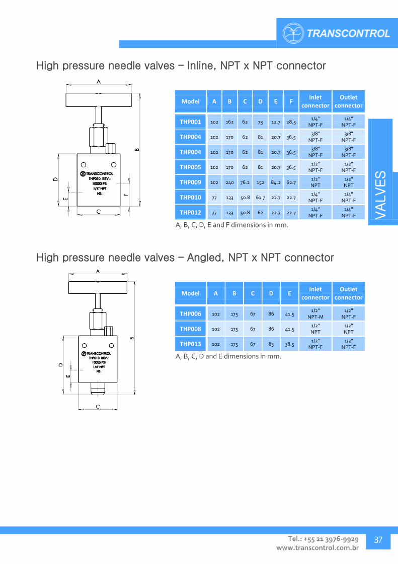
High pressure needle valves – Inline, NPT x NPT connector
Model A B C D E F Inlet
connector Outlet
connector
THP001 102 162 62 73 12.7 28.5 1/4"
NPT-F 1/4"
NPT-F
THP004 102 170 62 81 20.7 36.5 3/8"
NPT-F 3/8"
NPT-F
THP004 102 170 62 81 20.7 36.5 3/8"
NPT-F 3/8"
NPT-F
THP005 102 170 62 81 20.7 36.5 1/2"
NPT-F 1/2"
NPT-F
THP009 102 240 76.2 152 84.2 62.7 1/2" NPT
1/2" NPT
THP010 77 133 50.8 61.7 22.7 22.7 1/4"
NPT-F 1/4"
NPT-F
THP012 77 133 50.8 62 22.7 22.7 1/4"
NPT-F 1/4"
NPT-F
A, B, C, D, E and F dimensions in mm.
High pressure needle valves – Angled, NPT x NPT connector
Model A B C D E Inlet
connector Outlet
connector
THP006 102 175 67 86 41.5 1/2"
NPT-M 1/2"
NPT-F
THP008 102 175 67 86 41.5 1/2" NPT
1/2" NPT
THP013 102 175 67 83 38.5 1/2"
NPT-F 1/2"
NPT-F
A, B, C, D and E dimensions in mm.

VALVES
Transcontrol Catalog 2016 Edition – Rev. 01
VALVES
38
High pressure needle valves – Angled, API-LP x API-LP
connector
Model A B C D E Inlet
connector Outlet
connector
THP002 102 175 75 86 41.5 1/2"
API-LP-M 1/2"
API-LP-F
THP011 102 175 75 86 41.5 1/2"
API-LP-M 1/2"
API-LP-F
THP015 102 175 75 86 41.5 1/2"
API-LP-M 1/2"
API-LP-F
A, B, C, D and E dimensions in mm.
High pressure needle valves – Inline, SAE connector
Model A B C D E F Inlet
connector Outlet
connector
THP003 102 170 62 81 20.7 36.5 9/16" thread
18UNF-F 9/16" thread
18UNF-F
THP007 102 162 55 73 12.7 28.5 3/8" thread
24UNF-F 3/8" thread
24UNF-F
A, B, C, D, E and F dimensions in mm.
VALVES
Tel.: +55 21 3976-9929 www.transcontrol.com.br
39
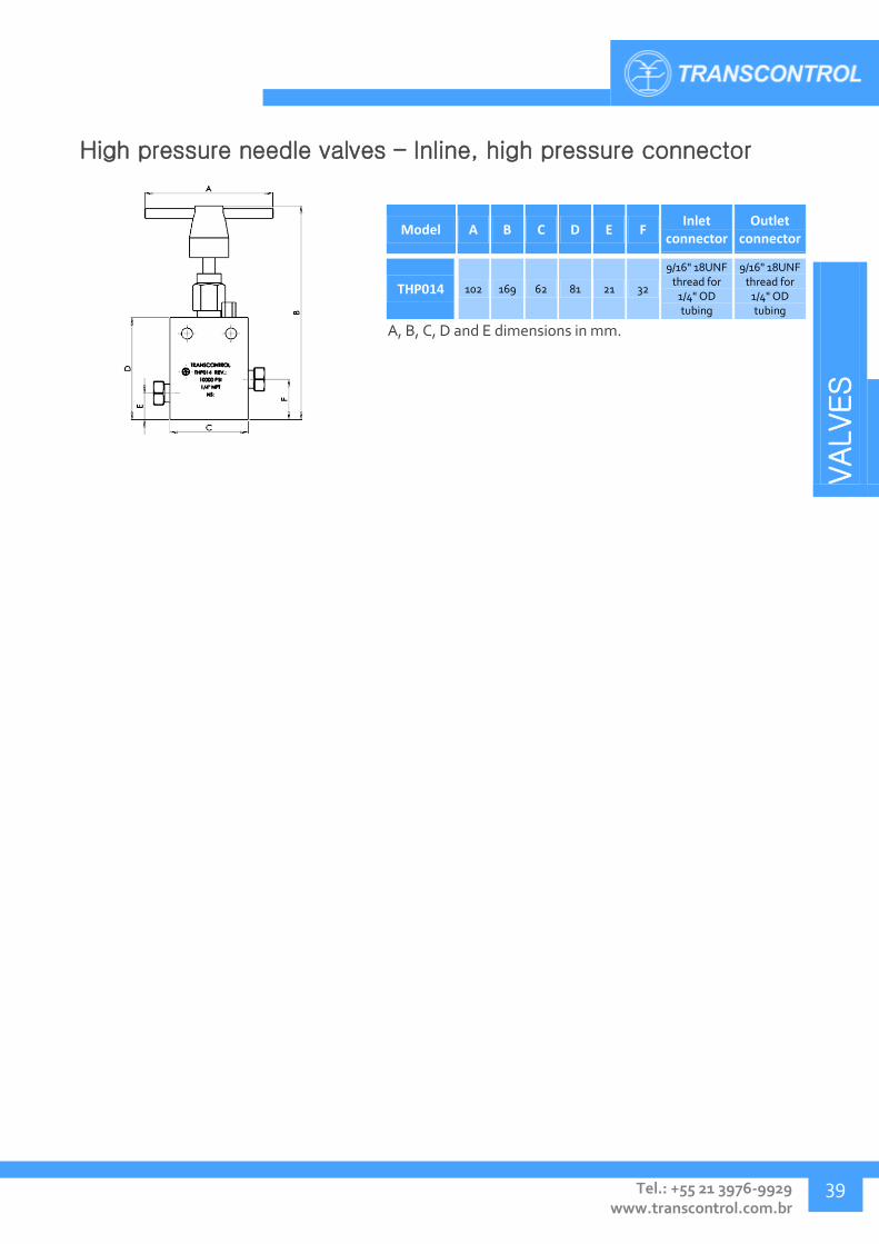
High pressure needle valves – Inline, high pressure connector
Model A B C D E F Inlet
connector Outlet
connector
THP014 102 169 62 81 21 32
9/16" 18UNF thread for
1/4" OD tubing
9/16" 18UNF thread for
1/4" OD tubing
A, B, C, D and E dimensions in mm.

VALVES
Transcontrol Catalog 2016 Edition – Rev. 01
VALVES
40
PRESSURE RELIEF VALVES – TVA
The TVA line of spring-actuated pressure relief valves were developed to offer superior reliability when acting as safety equipment countering overpressure or fluid expansion in hydraulic lines.
Application:
As safety equipment for hydraulic overpressure relief, protecting the system from damage to pressures of up to 16000 psi.
Technical Specification:
Pressure rating: up to 16.000 psi
Temperature range: 4° to 60ºC
Connectors: 1/4" NPT, 3/8" NPT, 1/2" NPT, 1" NPT, tubing 1/4" OD
Body material: AISI 316
Sealing type: Peek Soft Seal, Metal-Metal
Model Maximum relief
pressure (psi) Inlet connector Fluid release Drain connector Body material
TVA003 3200 1/4" NPT-M Free - AISI 316
TVA006 3200 3/8" NPT-M Free - AISI 316
TVA007 5490 3/8" NPT-M Drain connection 1/4/" NPT-F AISI 316
TVA008 3000 1/4" NPT-F Free - AISI 316
TVA009 5490 1/4" NPT-F Free - AISI 316
TVA010 100 1" NPT-F Free - AISI 316
TVA011 9000 1/2" NPT-F Drain connection 1/2" NPT-F AISI 316
TVA012 9000 1/4" NPT-F Drain connection 1/4" NPT-F AISI 316
TVA014 10000 1/4" NPT-F Drain connection 1/4" NPT-F AISI 316
TVA015 500 3/8" NPT-M Free - AISI 316
TVA016 2200 3/8" NPT-M Free - AISI 316
TVA017 950 1/2" NPT-M Free - AISI 316
TVA018 3000 3/8" NPT-M Drain connection 3/8" NPT-F AISI 316
TVA019 12000 1/4" NPT-F Drain connection 1/4" NPT-F AISI 316
TVA020 470 1/2" NPT-M Free - AISI 316
TVA021 5500 3/8" NPT-M Free - AISI 316
TVA022 1500 1/4" NPT-M Drain connection 1/4" NPT-F AISI 316
TVA023 16000 1/4" OD MP Drain connection 1/4" NPT-F AISI 316
TVA024 6000 1/4" NPT-F Drain connection 1/4" NPT-F AISI 316
TVA025 16000 1/4" NPT-F Drain connection 1/4" NPT-F AISI 316

VALVES
Tel.: +55 21 3976-9929 www.transcontrol.com.br
41
Relief valve – Free drain
Model A B C In / Out
connectors Drain
connector
TVA003 141 30 41 1/4"
NPT-M -
TVA006 141 30 41 3/8"
NPT-M -
TVA008 138 30 41 1/4"
NPT-F -
TVA009 126 30 41 1/4"
NPT-F -
TVA010 153 45 - 1"
NPT-F -
TVA015 142 33 41 3/8"
NPT-M -
TVA016 140 33 41 3/8"
NPT-M -
TVA017 145 33 41 1/2"
NPT-M -
TVA020 147 33 41 1/2"
NPT-M -
TVA021 141 33 41 3/8"
NPT-M -
A, B and C dimensions in mm.

VALVES
Transcontrol Catalog 2016 Edition – Rev. 01
VALVES
42
Relief valve – drain connection
Model A B C In / Out
connectors Drain
connector
TVA007 141 38 50 3/8"
NPT-M 1/4/"
NPT-F
TVA018 141 50 60 3/8"
NPT-M 3/8"
NPT-F
TVA019 183 38 - 1/4"
NPT-F 1/4"
NPT-F
TVA022 140 38 50 1/4"
NPT-M 1/4"
NPT-F
A, B and C dimensions in mm.
Relief valve – Inline, drain block
Model A B Inlet
connector Drain
connector
TVA011 167 44 1/2"
NPT-F 1/2"
NPT-F
TVA012 167 38 1/4"
NPT-F 1/4"
NPT-F
A and B dimensions in mm.
VALVES
Tel.: +55 21 3976-9929 www.transcontrol.com.br
43
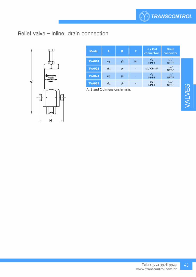
Relief valve – Inline, drain connection
Model A B C In / Out
connectors Drain
connector
TVA014 215 38 60 1/4"
NPT-F 1/4"
NPT-F
TVA023 183 46 - 1/4" OD MP 1/4"
NPT-F
TVA024 183 38 - 1/4"
NPT-F 1/4"
NPT-F
TVA025 183 48 - 1/4"
NPT-F 1/4"
NPT-F
A, B and C dimensions in mm.
VALVES
Transcontrol Catalog 2016 Edition – Rev. 01
VALVES
44
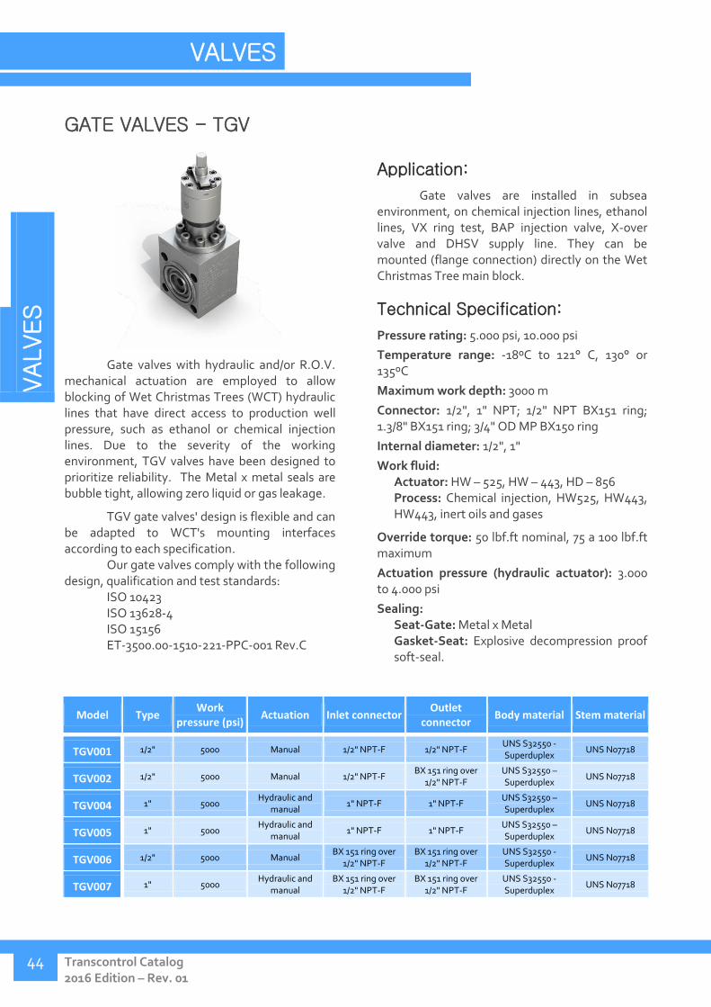
GATE VALVES - TGV
Gate valves with hydraulic and/or R.O.V. mechanical actuation are employed to allow blocking of Wet Christmas Trees (WCT) hydraulic lines that have direct access to production well pressure, such as ethanol or chemical injection lines. Due to the severity of the working environment, TGV valves have been designed to prioritize reliability. The Metal x metal seals are bubble tight, allowing zero liquid or gas leakage.
TGV gate valves' design is flexible and can be adapted to WCT's mounting interfaces according to each specification.
Our gate valves comply with the following design, qualification and test standards:
ISO 10423 ISO 13628-4 ISO 15156 ET-3500.00-1510-221-PPC-001 Rev.C
Application:
Gate valves are installed in subsea environment, on chemical injection lines, ethanol lines, VX ring test, BAP injection valve, X-over valve and DHSV supply line. They can be mounted (flange connection) directly on the Wet Christmas Tree main block.
Technical Specification:
Pressure rating: 5.000 psi, 10.000 psi
Temperature range: -18ºC to 121° C, 130° or 135ºC
Maximum work depth: 3000 m
Connector: 1/2", 1" NPT; 1/2" NPT BX151 ring; 1.3/8" BX151 ring; 3/4" OD MP BX150 ring
Internal diameter: 1/2", 1"
Work fluid: Actuator: HW – 525, HW – 443, HD – 856 Process: Chemical injection, HW525, HW443, HW443, inert oils and gases
Override torque: 50 lbf.ft nominal, 75 a 100 lbf.ft maximum
Actuation pressure (hydraulic actuator): 3.000 to 4.000 psi
Sealing: Seat-Gate: Metal x Metal Gasket-Seat: Explosive decompression proof soft-seal.
Model Type Work
pressure (psi) Actuation Inlet connector
Outlet connector
Body material Stem material
TGV001 1/2" 5000 Manual 1/2" NPT-F 1/2" NPT-F UNS S32550 - Superduplex
UNS N07718
TGV002 1/2" 5000 Manual 1/2" NPT-F BX 151 ring over
1/2" NPT-F UNS S32550 – Superduplex
UNS N07718
TGV004 1" 5000 Hydraulic and
manual 1" NPT-F 1" NPT-F
UNS S32550 – Superduplex
UNS N07718
TGV005 1" 5000 Hydraulic and
manual 1" NPT-F 1" NPT-F
UNS S32550 – Superduplex
UNS N07718
TGV006 1/2" 5000 Manual BX 151 ring over
1/2" NPT-F BX 151 ring over
1/2" NPT-F UNS S32550 - Superduplex
UNS N07718
TGV007 1" 5000 Hydraulic and
manual BX 151 ring over
1/2" NPT-F BX 151 ring over
1/2" NPT-F UNS S32550 - Superduplex
UNS N07718

VALVES
Tel.: +55 21 3976-9929 www.transcontrol.com.br
45
Model Type Work
pressure (psi) Actuation Inlet connector
Outlet connector
Body material Stem material
TGV008 1/2" 5000 Manual 1/2" NPT-F BX 150 ring over
MP 3/4" OD UNS S32550 – Superduplex
UNS N07718
TGV009 1" 5000 Hydraulic and
manual BX 151 ring flange BX 151 ring flange
UNS S32550 - Superduplex
UNS N07718
TGV010 1" 5000 Hydraulic and
manual Flanged Bonnet with BX 151 ring
- - UNS N06625
TGV011 1/2" 5000 Manual BX 150 ring over
MP 3/4" OD BX 150 ring over
MP 3/4" OD UNS S32550 - Superduplex
UNS N07718
TGV012 1/2" 5000 Manual BX 150 ring over
MP 3/4" OD BX 150 ring over
MP 3/4" OD UNS S32550 – Superduplex
UNS N07718
TGV013 1" 10000 Hydraulic and
manual BX 151 ring over 1.3/8" 12 UNF-2B
BX 151ring over 1.3/8" 12 UNF-2B
UNS S32550 - Superduplex
UNS N07718
The 1" type, class 5000 psi hydraulic / manual gate valves requires to be connected to the instrument block or Wet Christmas Tree's underwater pressure compensation system for proper operation.
In cases where an integrated pressure compensation system is not available, Transcontrol provides a Compensation Module, consisting of a compensation piston, check and relief valves. The Compensation Module, installed along the gate valve's frame, safely equalizes the pressure between the interior of the actuator assembly and the subsea environment.
For more information, contact Transcontrol.
Didn't find what you were looking for?
Contact Transcontrol. We develop projects and solutions according to your specifications.

VALVES
Transcontrol Catalog 2016 Edition – Rev. 01
VALVES
46
Gate valve – subsea, manual actuation, 1/2" internal diameter
Model A B C Inlet
connector Outlet
connector
TGV001 334 55 122 1/2" NPT - F 1/2" NPT - F
TGV002 378 66 127 1/2" NPT - F BX 151 ring over
1/2" NPT-F
TGV006 380 66 122 BX 151 ring over
1/2" NPT-F BX 151 ring over
1/2" NPT-F
TGV008 379 66 122 1/2" NPT - F BX 150 ring over
MP 3/4" OD
TGV011 367 66 124 BX 150 ring over
MP 3/4" OD BX 150 ring over
MP 3/4" OD
TGV012 367 66 124 BX 150 ring over
MP 3/4" OD BX 150 ring over
MP 3/4" OD
TGV015 334 55 122 MP 3/4" OD tubing MP 3/4" OD tubing
TGV016 377 66 122 BX 150 ring over
MP 3/4" OD MP 3/4" OD tubing
A, B and C dimensions in mm.
Gate valve – subsea, manual and hydraulic actuation, 1" internal
diameter
Model A B C Inlet
connector Outlet
connector
TGV004 612 85 149 1" NPT-F 1" NPT-F
TGV005 604 519 149 1" NPT-F 1" NPT-F
TGV007 653 85 160 BX 151 ring over
1/2" NPT-F BX 151 ring over
1/2" NPT-F
TGV009 623 85 190 BX 151 ring flange BX 151 ring flange
TGV013 654 84 194 BX 151 ring over 1.3/8" 12 UNF-2B
BX 151 ring over 1.3/8" 12 UNF-2B
A, B and C dimensions in mm.

VALVES
Tel.: +55 21 3976-9929 www.transcontrol.com.br
47
Gate valve – subsea, manual and hydraulic actuation, 1" internal
diameter, flanged bonnet mounting
Model A B C WCT connector
TGV010 482 85,75 Ø 232 BX 151 flanged bonnet
A, B and C dimensions in mm.

VALVES
Transcontrol Catalog 2016 Edition – Rev. 01
VALVES
48
PRESSURE CONTROL VALVES - TWO
In many hydraulic and pneumatic systems, the use of elements that limit, regulate, reduce or prevent unwanted pressure surges is necessary. TWO pressure control valves can be employed in hydraulic or pneumatic units and panels to fulfill this requirement, regulating and stabilizing the line output pressure.
Application:
Hydraulic power units and control panels, where a specific output fluid pressure is required.
Technical Specification:
Pressure rating: up to 10.000 psi
Output pressure: from 500 to 6.000 psi
Temperature range: 4° to 65ºC
Connector: 1/4", 3/8" NPT
Body material: AISI 316, brass
Seat material: AISI 316
Sealing type: Soft Seal
Model Input / output pressure (psi)
Fluid Inlet
connector Outlet
connector Body material
Restriction needle material
TWO001 10000/6000 Hydraulic 3/8" NPT - F 3/8" NPT - F AISI 316 17-4 PH
TWO002 6000/500 Pneumatic 1/4" NPT - F 1/4" NPT - F Brass AISI 316
TWO003 10000/4000 Hydraulic 3/8" NPT - F 3/8" NPT - F AISI 316 17-4 PH
TWO004 10000/4000 Hydraulic 1/4" NPT- F 1/4" NPT- F AISI 316 17-4 PH
TWO005 10000/6000 Hydraulic 1/4" NPT- F 1/4" NPT- F AISI 316 17-4 PH
TWO006 10000/500 Hydraulic 1/4" NPT - F 1/4" NPT - F AISI 316 17-4 PH
TWO007 10000/4000 Hydraulic 1/4" NPT- F 1/4" NPT- F AISI 316 17-4 PH
TWO009 6000/4000 Hydraulic
subsea 1/2" NPT - F 1/2" NPT - F AISI 316 AISI 316
TWO010 10000/4000 Hydraulic 3/8" NPT - F 3/8" NPT - F AISI 316 17-4 PH
TWO011 10000/1000 Hydraulic 3/8" NPT - F 3/8" NPT - F AISI 316 17-4 PH
TWO013 6000/2500 Pneumatic 1/4" NPT -F 1/4" NPT -F Brass AISI 316
TWO015 6000/500 Pneumatic 3/4" NPT -F 3/4" NPT -F Brass AISI 316
TWO016 3000/3000 Pneumatic 1/4" NPT - F 1/4" NPT - F Brass AISI 316
TWO017 10000/500 Pneumatic 1/4" NPT - F 1/4" NPT - F AISI 316 AISI 316
Didn't find what you were looking for?
Contact Transcontrol. We develop projects and solutions according to your specifications.

VALVES
Tel.: +55 21 3976-9929 www.transcontrol.com.br
49
Pressure control valve – hydraulic
Model A B C D Inlet
connector Outlet
connector
TWO001 63 183 81 71 3/8" NPT - F 3/8" NPT - F
TWO003 63 183 81 71 3/8" NPT - F 3/8" NPT - F
TWO004 63 183 81 71 1/4" NPT- F 1/4" NPT- F
TWO005 63 183 81 71 1/4" NPT- F 1/4" NPT- F
TWO006 63 183 81 71 1/4" NPT - F 1/4" NPT - F
TWO007 63 183 81 71 1/4" NPT- F 1/4" NPT- F
TWO010 63 183 81 71 3/8" NPT - F 3/8" NPT - F
TWO011 63 183 81 71 3/8" NPT - F 3/8" NPT - F
A, B, C and D dimensions in mm.
Pressure control valve – pneumatic
Model A B C D Inlet
connector Outlet
connector
TWO002 63 160 50 71 1/4" NPT - F 1/4" NPT - F
TWO013 63 160 50 71 1/4" NPT -F 1/4" NPT -F
TWO015 63 166.5 70 71 3/4" NPT -F 3/4" NPT -F
TWO016 63 160 50 71 1/4" NPT - F 1/4" NPT - F
TWO017 63 160 50 71 1/4" NPT - F 1/4" NPT - F
A, B, C and D dimensions in mm.
Pressure control valve – hydraulic subsea
Model A B C D Inlet
connector Outlet
connector
TWO009 48.5 172 166 74 1/2" NPT - F 1/2" NPT - F
A, B, C and D dimensions in mm.

VALVES
Transcontrol Catalog 2016 Edition – Rev. 01
VALVES
50
HIGH FLOW HIGH PRESSURE CONTROL VALVES - TRT
TRT high flow high pressure control valves were developed to be installed in hydraulic systems where output pressure stabilization is necessary, but high flow is expected. Frequently used in BOP, this line of valves can be installed in subsea environments.
Application:
Surface hydraulic units, panels and systems or subsea systems.
Technical Specification:
Pressure rating: up to 6.000 psi
Output pressure range: 0 to 5.000 psi
Temperature range: 4° to 65ºC
Connector: 1/2", 1" NPT
Internal diameter: 1"
Body material: AISI 316
Seat material: AISI 316
Sealing type: Metal x metal
Model Input
pressure (psi)
Output pressure
(psi)
Inlet connector
Outlet connector
Drain connector
Auxiliary output
connector Material
TRT001 5000 500-3000 1" NPT-F 1" NPT-F 1/2" NPT-F 3/8" NPT-F AISI 316
TRT002 5000 0-1500 1" NPT-F 1" NPT-F 1/2" NPT-F 3/8" NPT-F AISI 316
TRT003 6000 1000-5000 1" NPT-F 1" NPT-F 1/2" NPT-F 3/8" NPT-F AISI 316
TRT004 5000 500-3000 1/2" NPT-F 1/2" NPT-F 1/4/" NPT-F 1/4/" NPT-F AISI 316
Didn't find what you were looking for?
Contact Transcontrol. We develop projects and solutions according to your specifications.
VALVES
Tel.: +55 21 3976-9929 www.transcontrol.com.br
51
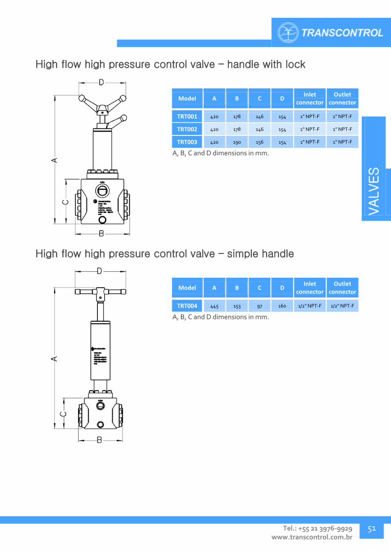
High flow high pressure control valve – handle with lock
Model A B C D Inlet
connector Outlet
connector
TRT001 420 178 146 154 1" NPT-F 1" NPT-F
TRT002 420 178 146 154 1" NPT-F 1" NPT-F
TRT003 420 190 156 154 1" NPT-F 1" NPT-F
A, B, C and D dimensions in mm.
High flow high pressure control valve – simple handle
Model A B C D Inlet
connector Outlet
connector
TRT004 445 153 97 160 1/2" NPT-F 1/2" NPT-F
A, B, C and D dimensions in mm.

VALVES
Transcontrol Catalog 2016 Edition – Rev. 01
VALVES
52
SHUTTLE VALVES - TSV
Shuttle valves allow directional control of fluid between two or more outlets, through actuation of a central stem. The simplicity of the internal mechanism confers to the valve excellent reliability.
TSV shuttle valves are available with manual or hydraulic actuation and spring or pressure differential return.
Application:
Shuttle valves can be used in surface or subsea hydraulic systems to perform directional fluid flow control, such as alternating between different pressure range inputs.
Technical Specification:
Pressure rating: up to 10.000 psi
Pilot pressure: 1.500 to 5.000 psi
Temperature range: 4° to 65ºC
Depth: up to 2500 m.
Connector: 3/8", 1" NPT
Body material: AISI 316
Sealing type: Soft Seal, Metal-Metal
Model Work pressure
(psi) Inlet / outlet connectors
Pilot connector Body material Stem material Hydraulic diagram
TSV001 5000 3/8" NPT-F - AISI 316 ASTM A564 TP 630-
17-4PH
TSV002 5000 3/8" NPT-F 1"-20UNEF-2B AISI 316 UNS N07718
TSV003 6000 3/8" NPT-F - AISI 316 ASTM A564 TP 630-
17-4PH
TSV004 10000 1/2" NPT - AISI 316 ASTM A564 TP 630
-17 -4PH
TSV005 5000 1" NPT - AISI 316 AISI 420
TSV006 5000 3/8" NPT-F 3/8" NPT-F AISI 316 UNS N07718
TSV007 3000 3/8" NPT-F - AISI 316 UNS N07718
TSV008 3000 3/8" NPT-F 1"-20UNEF-2B AISI 316 UNS N07718
TSV009 5000 3/8" NPT-F 3/8" NPT-F AISI 316 UNS N07718

VALVES
Tel.: +55 21 3976-9929 www.transcontrol.com.br
53
Model Work pressure
(psi) Inlet / outlet connectors
Pilot connector Body material Stem material Hydraulic diagram
TSV010 5000 3/8" NPT-F - AISI 316 ASTM A564 TP 630-
17-4PH
TSV011 3000 3/8" NPT-F 1"-20UNEF-2B AISI 316 UNS N07718
TSV012 3000 3/8" NPT-F 3/8" NPT-F AISI 316 UNS N07718
TSV013 5000 3/8" NPT-F - AISI 316 ASTM A564 TP 630
-17 -4PH
TSV014 3000 3/8" NPT-F 3/8" NPT-F AISI 316 UNS N07718
TSV015 3000 3/8" NPT-F - AISI 316 AISI 420
TSV016 10000 3/8" NPT-F - AISI 316 AISI 420
TSV017 5000 1" NPT - AISI 316 UNS N06625
TSV018 10000 1/4" NPT - AISI 316 ASTM A564 TP 630
-17 -4PH
TSV020 5000 3/8" NPT-F 1"-20UNEF-2B AISI 316 UNS N07718
Didn't find what you were looking for?
Contact Transcontrol. We develop projects and solutions according to your specifications.
VALVES
Transcontrol Catalog 2016 Edition – Rev. 01
VALVES
54
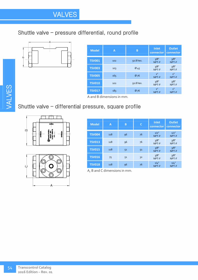
Shuttle valve – pressure differential, round profile
Model A B Inlet
connector Outlet
connector
TSV001 102 50.8 hex. 3/8"
NPT-F 3/8"
NPT-F
TSV003 103 Ø 45 3/8"
NPT-F 3/8"
NPT-F
TSV005 165 Ø 76 1"
NPT-F 1"
NPT-F
TSV010 102 50.8 hex. 3/8"
NPT-F 3/8"
NPT-F
TSV017 183 Ø 76 1"
NPT-F 1"
NPT-F
A and B dimensions in mm.
Shuttle valve – differential pressure, square profile
Model A B C Inlet
connector Outlet
connector
TSV004 118 96 76 1/2"
NPT-F 1/2"
NPT-F
TSV013 118 96 76 3/8"
NPT-F 3/8"
NPT-F
TSV015 118 51 51 3/8"
NPT-F 3/8"
NPT-F
TSV016 75 51 32 3/8"
NPT-F 3/8"
NPT-F
TSV018 118 96 76 1/4"
NPT-F 1/4"
NPT-F
A, B and C dimensions in mm.

VALVES
Tel.: +55 21 3976-9929 www.transcontrol.com.br
55
Shuttle valve – hydraulic pilot
Model A B C Inlet
connector Outlet
connector Pilot
connector
TSV002 302 76 26 3/8"
NPT-F 3/8"
NPT-F 1"
-20UNEF-2B
TSV006 299 76 47 3/8"
NPT-F 3/8"
NPT-F 3/8"
NPT-F
TSV007 376 76 35 3/8"
NPT-F 3/8"
NPT-F -
TSV008 302 76 - 3/8"
NPT-F 3/8"
NPT-F 1"
-20UNEF-2B
TSV009 302 76 - 3/8"
NPT-F 3/8"
NPT-F 3/8"
NPT-F
TSV011 302 76 47 3/8"
NPT-F 3/8"
NPT-F 1"
-20UNEF-2B
TSV012 302 76 26 3/8"
NPT-F 3/8"
NPT-F 3/8"
NPT-F
TSV014 302 76 - 3/8"
NPT-F 3/8"
NPT-F 3/8"
NPT-F
TSV020 229 76 26 3/8"
NPT-F 3/8"
NPT-F 1"
-20UNEF-2B
A, B and C dimensions in mm.
VALVES
Transcontrol Catalog 2016 Edition – Rev. 01
VALVES
56
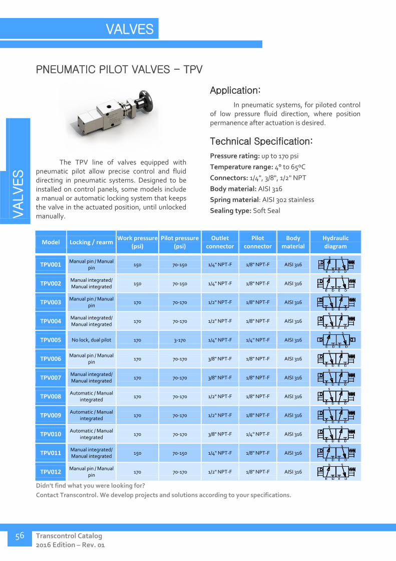
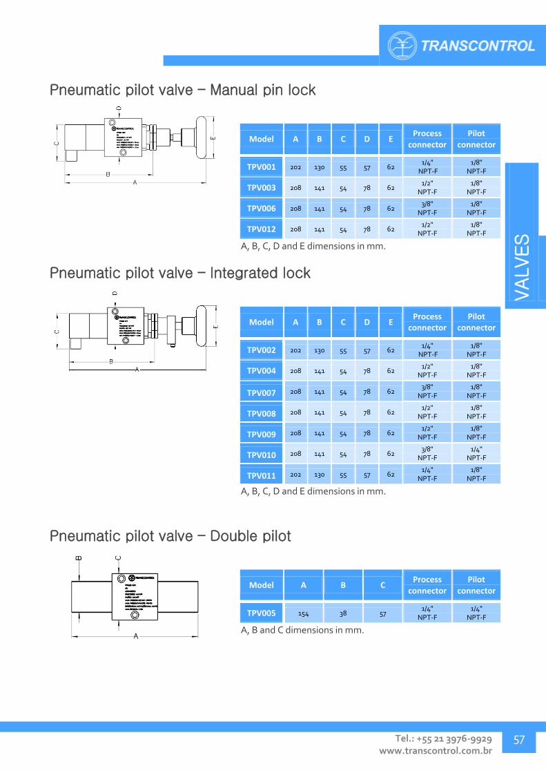
PNEUMATIC PILOT VALVES - TPV
The TPV line of valves equipped with pneumatic pilot allow precise control and fluid directing in pneumatic systems. Designed to be installed on control panels, some models include a manual or automatic locking system that keeps the valve in the actuated position, until unlocked manually.
Application:
In pneumatic systems, for piloted control of low pressure fluid direction, where position permanence after actuation is desired.
Technical Specification:
Pressure rating: up to 170 psi
Temperature range: 4° to 65ºC
Connectors: 1/4", 3/8", 1/2" NPT
Body material: AISI 316
Spring material: AISI 302 stainless
Sealing type: Soft Seal
Model Locking / rearm Work pressure
(psi) Pilot pressure
(psi) Outlet
connector Pilot
connector Body
material Hydraulic diagram
TPV001 Manual pin / Manual
pin 150 70-150 1/4" NPT-F 1/8" NPT-F AISI 316
TPV002 Manual integrated/ Manual integrated
150 70-150 1/4" NPT-F 1/8" NPT-F AISI 316
TPV003 Manual pin / Manual
pin 170 70-170 1/2" NPT-F 1/8" NPT-F AISI 316
TPV004 Manual integrated/ Manual integrated
170 70-170 1/2" NPT-F 1/8" NPT-F AISI 316
TPV005 No lock, dual pilot 170 3-170 1/4" NPT-F 1/4" NPT-F AISI 316
TPV006 Manual pin / Manual
pin 170 70-170 3/8" NPT-F 1/8" NPT-F AISI 316
TPV007 Manual integrated/ Manual integrated
170 70-170 3/8" NPT-F 1/8" NPT-F AISI 316
TPV008 Automatic / Manual
integrated 170 70-170 1/2" NPT-F 1/8" NPT-F AISI 316
TPV009 Automatic / Manual
integrated 170 70-170 1/2" NPT-F 1/8" NPT-F AISI 316
TPV010 Automatic / Manual
integrated 170 70-170 3/8" NPT-F 1/4" NPT-F AISI 316
TPV011 Manual integrated/ Manual integrated
150 70-150 1/4" NPT-F 1/8" NPT-F AISI 316
TPV012 Manual pin / Manual
pin 170 70-170 1/2" NPT-F 1/8" NPT-F AISI 316
Didn't find what you were looking for?
Contact Transcontrol. We develop projects and solutions according to your specifications.
VALVES
Tel.: +55 21 3976-9929 www.transcontrol.com.br
57
Pneumatic pilot valve – Manual pin lock
Model A B C D E Process
connector Pilot
connector
TPV001 202 130 55 57 62 1/4"
NPT-F 1/8"
NPT-F
TPV003 208 141 54 78 62 1/2"
NPT-F 1/8"
NPT-F
TPV006 208 141 54 78 62 3/8"
NPT-F 1/8"
NPT-F
TPV012 208 141 54 78 62 1/2"
NPT-F 1/8"
NPT-F
A, B, C, D and E dimensions in mm.
Pneumatic pilot valve – Integrated lock
Model A B C D E Process
connector Pilot
connector
TPV002 202 130 55 57 62 1/4"
NPT-F 1/8"
NPT-F
TPV004 208 141 54 78 62 1/2"
NPT-F 1/8"
NPT-F
TPV007 208 141 54 78 62 3/8"
NPT-F 1/8"
NPT-F
TPV008 208 141 54 78 62 1/2"
NPT-F 1/8"
NPT-F
TPV009 208 141 54 78 62 1/2"
NPT-F 1/8"
NPT-F
TPV010 208 141 54 78 62 3/8"
NPT-F 1/4"
NPT-F
TPV011 202 130 55 57 62 1/4"
NPT-F 1/8"
NPT-F
A, B, C, D and E dimensions in mm.
Pneumatic pilot valve – Double pilot
Model A B C Process
connector Pilot
connector
TPV005 154 38 57 1/4"
NPT-F 1/4"
NPT-F
A, B and C dimensions in mm.

VALVES
Transcontrol Catalog 2016 Edition – Rev. 01
VALVES
58
HIGH-LOW PILOT VALVES - THL
The High-low pilot valve has been designed to designate the supply line, between two lines of different pressure ranges. For operation, the valve is actuated hydraulically.
This kind of valve is frequently employed in the supply line for pneumatic cylinders, where a pre-charge pressure is necessary in order to reduce actuation delay.
Application:
In pneumatic systems, for piloted control of supply lines of different pressure ranges; or in the supply line of pneumatic equipment that require pre-charge.
Technical Specification:
Pressure rating: 150 psi
Temperature range: 4° to 65ºC
Connectors: 1/4" NPT
Body material: AISI 316
Spring material: AISI 1065
Spring housing material: Brass
Sealing type: Soft Seal
Model High
pressure (psi) Low pressure
(psi) Pilot pressure (min-max, psi)
Process connector
Pilot connector
Body material
Hydraulic diagram
THL001 150 7 7-150 1/4" NPT-F 1/2" NPT-M AISI 316
THL002 150 70 12000-13000 1/4" NPT-F 3/8" NPT-M AISI 316
THL003 150 70 1490-1560 1/4" NPT-F 1/2" NPT-M AISI 316
THL004 150 70 2840-5120 1/4" NPT-F 1/2" NPT-M AISI 316
Didn't find what you were looking for?
Contact Transcontrol. We develop projects and solutions according to your specifications.
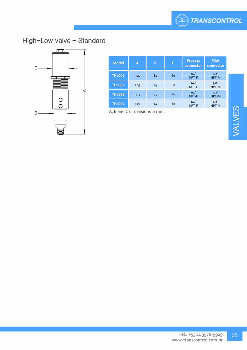
VALVES
Tel.: +55 21 3976-9929 www.transcontrol.com.br
59
High-Low valve – Standard
Model A B C Process
connector Pilot
connector
THL001 301 81 60 1/4"
NPT-F 1/2"
NPT-M
THL002 205 44 60 1/4"
NPT-F 3/8"
NPT-M
THL003 303 44 60 1/4"
NPT-F 1/2"
NPT-M
THL004 303 44 60 1/4"
NPT-F 1/2"
NPT-M
A, B and C dimensions in mm.

VALVES
Transcontrol Catalog 2016 Edition – Rev. 01
VALVES
60
CHECK VALVES - TCV
Check valves are commonly employed in hydraulic systems to allow fluid flow in one direction only. Simple check valves operate automatically, whereas some models can be piloted hydraulically to fully block passage or allow the fluid to flow in the inverse direction.
Application:
Used for one-way fluid flow in hydraulic power units, control panels, supply pumps and process systems. Can be employed in onshore, offshore or subsea environments.
Technical Specification:
Pressure rating: up to 15.000 psi
Temperature range: 4° to 65ºC
Connector: 1/4", 3/8", 1/2", 9/16" and 3/4" NPT, 1/4", 3/8", 1/2" and 3/4" OD/DA, 7/16" JIC-04-37°, 9/16" MP, 1/8" SAE
Body material: AISI 316, UNS S32750 Superduplex, AISI 4340
Spring material: AISI 302 stainless
Sealing: Soft-seal, Metal-metal
Model Work
pressure (psi) Cracking
pressure (psi) Type
Inlet connector
Outlet connector
Pilot connector
Body material
Hydraulic diagram
TCV001 100 20 a 50 Piston 1/4" NPT-M 1/8" NPT-F - AISI 316
TCV002 100 20 a 50 Piston 1/8" SAE 1/8" NPT-F - AISI 316
TCV003 5000 25 Piston 3/8" NPT-F 3/8" NPT-F - AISI 316
TCV004 5000 25 Piston 3/8" NPT-M 3/8" NPT-M - AISI 316
TCV005 6000 25 Piston 3/8" OD/DA 3/8" OD/DA - AISI 316
TCV006 5000 25 Piston 3/8" OD/DA 3/8" OD/DA - AISI 316
TCV007 6000 25 Piston 3/8" NPT-F 3/8" NPT-F - AISI 316
TCV008 10000 25 Piston 3/8" NPT-F 3/8" NPT-F - AISI 316
TCV009 6000 25 Piston 1/2" NPT-F 1/2" NPT-F - AISI 316
TCV010 10000 25 Piston 1/2" NPT-F 1/2" NPT-F - AISI 316
TCV011 5000 25 Ball 3/8" NPT-F 3/8" NPT-F - AISI 316
TCV012 5000 25 Ball 3/8" NPT-F 3/8" NPT-F - UNS S32750 Superduplex
TCV013 6000 25 Ball 3/8" NPT-F 3/8" NPT-F - AISI 316

VALVES
Tel.: +55 21 3976-9929 www.transcontrol.com.br
61
Model Work
pressure (psi) Cracking
pressure (psi) Type
Inlet connector
Outlet connector
Pilot connector
Body material
Hydraulic diagram
TCV015 6000 25 Ball 1/2" NPT-F 1/2" NPT-F - AISI 316
TCV016 6000 25 Ball 1/4" NPT-F 1/4" OD/DA - AÇO AISI
4340
TCV018 6000 25 Ball 1/4" NPT-F 1/4" NPT-F - AISI 316
TCV019 5000 1900 a 2200 Piston Piloted
1/2" NPT-F 1/2" NPT-F 1/4" NPT-F AISI 316
TCV020 10000 25 Piston 1/4" NPT-F 1/4" NPT-F - AISI 316
TCV021 6000 25 Piston 1/4"NPT-M 1/4" NPT-M - AISI 316
TCV022 5000 - Pressure
differential 1/2" NPT-F 1/2" NPT-F - AISI 316
TCV024 6000 25 Piston 1/2" OD/DA 1/2" OD/DA - AISI 316
TCV025 1500 400 Piston piloted
1/2" NPT-F 1/2" NPT-F 1/4" NPT-F AISI 316
TCV026 500 25 Ball 1/4" NPT-M 1/4" NPT-F - AISI 316
TCV027 5000 1000 Piston piloted
1/2" NPT-F 1/2" NPT-F 1/4" NPT-F AISI 316
TCV028 5000 900 Piston 1/2" NPT-F 1/2" NPT-F - UNS S32750 Superduplex
TCV029 5000 1000 Piston piloted
1/2" NPT-F 1/2" NPT-F 1/4" NPT-F AISI 316
TCV030 5000 8 Piston 3/4" NPT-F 3/4" NPT-F - AISI 316
TCV031 5000 1200 a 1800 Piston piloted
1/2" NPT-F 1/2" NPT-F 1/4" NPT-F AISI 316
TCV033 3000 600 Piston piloted
1/2" NPT-F 1/2" NPT-F 3/8" NPT-F AISI 316
TCV035 5000 25 Piston 7/16" JIC-04-37° 1/4" NPT-M - AISI 316
TCV036 5000 8 Piston 3/4" OD/DA 3/4" OD/DA - AISI 316
TCV037 15000 25 Piston 3/8" NPT-F 3/8" NPT-F - UNS S32750 Superduplex
TCV038 5000 25 Piston 7/16" JIC-04-37° 1/8" NPT-M - AISI 316
TCV039 5000 600 Piston piloted
1/2" NPT-F 1/2" NPT-F 3/8" NPT-F AISI 316
TCV041 5000 8 Piston 3/4" BSP 3/4" BSP - AISI 316
TCV042 3000 500 Piston piloted
3/8" NPT-F 3/8" NPT-F 1/4" NPT-F AISI 316
TCV043 10000 25 Piston 9/16" NPT-F 9/16" NPT-F - AISI 316
TCV044 10000 25 Ball 9/16" NPT-F 9/16" NPT-F - AISI 316
Didn't find what you were looking for?
Contact Transcontrol. We develop projects and solutions according to your specifications.
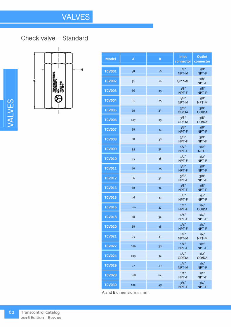
VALVES
Transcontrol Catalog 2016 Edition – Rev. 01
VALVES
62
Check valve – Standard
Model A B Inlet
connector Outlet
connector
TCV001 38 16 1/4"
NPT-M 1/8"
NPT-F
TCV002 32 16 1/8" SAE 1/8"
NPT-F
TCV003 86 25 3/8"
NPT-F 3/8"
NPT-F
TCV004 91 25 3/8"
NPT-M 3/8"
NPT-M
TCV005 99 32 3/8"
OD/DA 3/8"
OD/DA
TCV006 107 25 3/8"
OD/DA 3/8"
OD/DA
TCV007 88 32 3/8"
NPT-F 3/8"
NPT-F
TCV008 88 38 3/8"
NPT-F 3/8"
NPT-F
TCV009 95 32 1/2"
NPT-F 1/2"
NPT-F
TCV010 95 38 1/2"
NPT-F 1/2"
NPT-F
TCV011 86 25 3/8"
NPT-F 3/8"
NPT-F
TCV012 86 32 3/8"
NPT-F 3/8"
NPT-F
TCV013 88 32 3/8"
NPT-F 3/8"
NPT-F
TCV015 96 32 1/2"
NPT-F 1/2"
NPT-F
TCV016 100 37 1/4"
NPT-F 1/4"
OD/DA
TCV018 88 32 1/4"
NPT-F 1/4"
NPT-F
TCV020 88 38 1/4"
NPT-F 1/4"
NPT-F
TCV021 94 32 1/4"
NPT-M 1/4"
NPT-M
TCV022 100 38 1/2"
NPT-F 1/2"
NPT-F
TCV024 109 32 1/2"
OD/DA 1/2"
OD/DA
TCV026 27 19 1/4"
NPT-M 1/4"
NPT-F
TCV028 108 64 1/2"
NPT-F 1/2"
NPT-F
TCV030 102 45 3/4"
NPT-F 3/4"
NPT-F
A and B dimensions in mm.

VALVES
Tel.: +55 21 3976-9929 www.transcontrol.com.br
63
Check valve – Standard (cont.)
Model A B Inlet
connector Outlet
connector
TCV035 52 16 7/16"
JIC-04-37° 1/4"
NPT-M
TCV036 123 45 3/4"
OD/DA 3/4"
OD/DA
TCV037 88 41 3/8"
NPT-F 3/8"
NPT-F
TCV038 49 16 7/16"
JIC-04-37° 1/8"
NPT-M
TCV041 102 45 3/4" BSP
3/4" BSP
TCV043 113 38 9/16"
NPT-F 9/16"
NPT-F
TCV044 120 38 9/16"
NPT-F 9/16"
NPT-F
A and B dimensions in mm.
Check valve - Piloted
Model A B C Inlet
connector Outlet
connector Pilot
connector
TCV019 139 48 68 1/2"
NPT-F 1/2"
NPT-F 1/4"
NPT-F
TCV025 139 48 68 1/2"
NPT-F 1/2"
NPT-F 1/4"
NPT-F
TCV027 139 48 68 1/2"
NPT-F 1/2"
NPT-F 1/4"
NPT-F
TCV029 139 48 68 1/2"
NPT-F 1/2"
NPT-F 1/4"
NPT-F
TCV031 166 61 68 1/2"
NPT-F 1/2"
NPT-F 1/4"
NPT-F
TCV033 139 48 68 1/2"
NPT-F 1/2"
NPT-F 3/8"
NPT-F
TCV039 142 48 71 1/2"
NPT-F 1/2"
NPT-F 3/8"
NPT-F
TCV042 139 48 68 3/8"
NPT-F 3/8"
NPT-F 1/4"
NPT-F
A, B and C dimensions in mm.
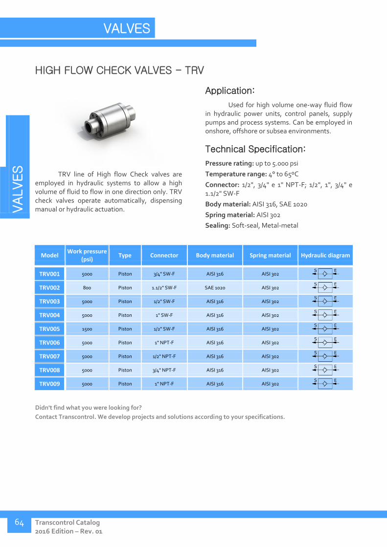
VALVES
Transcontrol Catalog 2016 Edition – Rev. 01
VALVES
64
HIGH FLOW CHECK VALVES - TRV
TRV line of High flow Check valves are employed in hydraulic systems to allow a high volume of fluid to flow in one direction only. TRV check valves operate automatically, dispensing manual or hydraulic actuation.
Application:
Used for high volume one-way fluid flow in hydraulic power units, control panels, supply pumps and process systems. Can be employed in onshore, offshore or subsea environments.
Technical Specification:
Pressure rating: up to 5.000 psi
Temperature range: 4° to 65ºC
Connector: 1/2", 3/4" e 1" NPT-F; 1/2", 1", 3/4" e 1.1/2" SW-F
Body material: AISI 316, SAE 1020
Spring material: AISI 302
Sealing: Soft-seal, Metal-metal
Model Work pressure
(psi) Type Connector Body material Spring material Hydraulic diagram
TRV001 5000 Piston 3/4" SW-F AISI 316 AISI 302
TRV002 800 Piston 1.1/2" SW-F SAE 1020 AISI 302
TRV003 5000 Piston 1/2" SW-F AISI 316 AISI 302
TRV004 5000 Piston 1" SW-F AISI 316 AISI 302
TRV005 1500 Piston 1/2" SW-F AISI 316 AISI 302
TRV006 5000 Piston 1" NPT-F AISI 316 AISI 302
TRV007 5000 Piston 1/2" NPT-F AISI 316 AISI 302
TRV008 5000 Piston 3/4" NPT-F AISI 316 AISI 302
TRV009 5000 Piston 1" NPT-F AISI 316 AISI 302
Didn't find what you were looking for?
Contact Transcontrol. We develop projects and solutions according to your specifications.
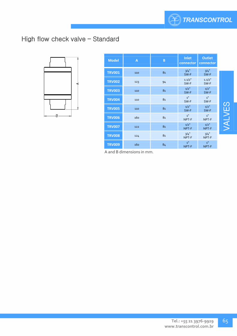
VALVES
Tel.: +55 21 3976-9929 www.transcontrol.com.br
65
High flow check valve – Standard
Model A B Inlet
connector Outlet
connector
TRV001 110 81 3/4"
SW-F 3/4"
SW-F
TRV002 123 94 1.1/2" SW-F
1.1/2" SW-F
TRV003 110 81 1/2"
SW-F 1/2"
SW-F
TRV004 110 81 1"
SW-F 1"
SW-F
TRV005 110 81 1/2"
SW-F 1/2"
SW-F
TRV006 160 81 1"
NPT-F 1"
NPT-F
TRV007 122 81 1/2"
NPT-F 1/2"
NPT-F
TRV008 124 81 3/4"
NPT-F 3/4"
NPT-F
TRV009 160 84 1"
NPT-F 1"
NPT-F
A and B dimensions in mm.
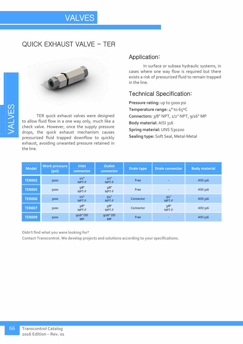
VALVES
Transcontrol Catalog 2016 Edition – Rev. 01
VALVES
66
QUICK EXHAUST VALVE - TER
TER quick exhaust valves were designed to allow fluid flow in a one way only, much like a check valve. However, once the supply pressure drops, the quick exhaust mechanism causes pressurized fluid trapped downflow to quickly exhaust, avoiding unwanted pressure retained in the line.
Application:
In surface or subsea hydraulic systems, in cases where one way flow is required but there exists a risk of pressurized fluid to remain trapped in the line.
Technical Specification:
Pressure rating: up to 5000 psi
Temperature range: 4° to 65ºC
Connectors: 3/8" NPT, 1/2" NPT, 9/16" MP
Body material: AISI 316
Spring material: UNS S30200
Sealing type: Soft Seal, Metal-Metal
Model Work pressure
(psi) Inlet
connector Outlet
connector Drain type Drain connector Body material
TER002 5000 1/2"
NPT-F 1/2"
NPT-F Free - AISI 316
TER005 5000 3/8"
NPT-F 3/8"
NPT-F Free - AISI 316
TER006 3000 1/2"
NPT-F 3/4"
NPT-F Connector
3/4" NPT-F
AISI 316
TER007 5000 3/8"
NPT-F 3/8"
NPT-F Connector
3/8" NPT-F
AISI 316
TER009 5000 9/16" OD
MP 9/16" OD
MP Free - AISI 316
Didn't find what you were looking for?
Contact Transcontrol. We develop projects and solutions according to your specifications.

VALVES
Tel.: +55 21 3976-9929 www.transcontrol.com.br
67
Quick Exhaust Valve – Free drain
Model A B Inlet
connector Outlet
connector
TER002 252 74 1/2"
NPT-F 1/2"
NPT-F
TER005 116 38 hex. 3/8"
NPT-F 3/8"
NPT-F
TER009 136 38 9/16" OD MP 9/16" OD MP
A and B dimensions in mm.
Quick Release Valve – Connector drain
Model A B Inlet
connector Outlet
connector Drain
connector
TER006 272 74 1/2"
NPT-F 3/4"
NPT-F 3/4"
NPT-F
TER007 116 54 3/8"
NPT-F 3/8"
NPT-F 3/8"
NPT-F
A and B dimensions in mm.

VALVES
Transcontrol Catalog 2016 Edition – Rev. 01
VALVES
68
DIRECTIONAL VALVES - TVS
Directional valves allow the redirecting of fluid flow to one or more outlets, exclusive or simultaneously, according to the valve's configuration. TVS directional valves are frequently employed in hydraulic panels and control systems.
Application:
Valves with manual or interface actuation are employed in control panels and hydraulic systems, in onshore or offshore environments.
Technical Specification:
Pressure rating: up to 10.000 psi
Temperature range: 4° to 65ºC
Connector: 1/4", 3/8", 1/2" e 1" NPT
Body material: AISI 316
Sealing material: PEEK, UNS S42000
Sealing type: Soft Seal, Metal-Metal
Model Work pressure
(psi) Ways /
positions Actuation Inlet connector Body material Hydraulic diagram
TVS018 10000 4/3 Manual 3/8" NPT-F AISI 316
TVS026 3000 4/2 Manual 1" NPT-F AISI 316
TVS027 5000 4/3 Manual 1" NPT-F AISI 316
TVS028 5000 4/3 Manual 1" NPT-F AISI 316
TVS030 10000 4/3 Manual 1/4" NPT-F AISI 316
TVS031 10000 3/3 Manual 1/4" NPT-F AISI 316
TVS047 5000 4/3 Manual 1" NPT-F AISI 316
TVS048 5000 3/2 Manual 1" NPT-F AISI 316
TVS049 5000 4/3 Manual 1" NPT-F AISI 316
TVS050 5000 4/3 Manual 1" NPT-F AISI 316
TVS066 10000 4/3 Manual 3/8" NPT-F AISI 316
TVS070 3000 4/3 Manual 1" NPT-F AISI 316

VALVES
Tel.: +55 21 3976-9929 www.transcontrol.com.br
69
Model Work pressure
(psi) Ways /
positions Actuation Inlet connector Body material Hydraulic diagram
TVS081 5000 4/3 Manual 1/4" NPT-F AISI 316
TSV089 6000 3/3 Manual with
transfer manifold 1/4" NPT-F AISI 316
TVS090 10000 2/2 Manual 1/2" NPT-F AISI 316
Transcontrol is aware of the challenges that emerge
during hydraulic system operation, and innovates on developing
equipment that offers efficient solutions.
TSV089 directional valve integrates a transfer manifold,
designed to allow quick blocking of the pressurized line, in case of
a necessity to intervene on the directional valve. This function
ensures a safer, more agile and economic maintenance process.
Didn't find what you were looking for?
Contact Transcontrol. We develop projects and solutions according to your specifications.

VALVES
Transcontrol Catalog 2016 Edition – Rev. 01
VALVES
70
Directional valve – Manual actuation
Model A B C Inlet
connector
TVS026 219 120 216 1"
NPT-F
TVS027 219 120 216 1"
NPT-F
TVS028 219 120 216 1"
NPT-F
TVS047 219 120 216 1"
NPT-F
TVS048 219 120 216 1"
NPT-F
TVS049 219 120 216 1"
NPT-F
TVS050 219 120 216 1"
NPT-F
TVS070 226 120 213 1"
NPT-F
A, B and C dimensions in mm.
Directional valve – Manual actuation, panel fixture
Model A B C D Inlet
connector
TVS026 135 70 142 48,2 1"
NPT-F
A, B, C and D dimensions in mm.

VALVES
Tel.: +55 21 3976-9929 www.transcontrol.com.br
71
Directional valve – Manual actuation, flanged
Model A B C D Inlet
connector
TVS018 197 89 102 160 3/8"
NPT-F
TVS030 197 89 102 160 1/4"
NPT-F
TVS031 197 89 102 160 1/4"
NPT-F
TVS066 197 89 102 160 3/8"
NPT-F
TVS090 204 89 102 160 1/2"
NPT-F
A, B, C and D dimensions in mm.
Directional valve – Manual actuation, with transfer manifold and
pressure gauge
Model A B C D E Inlet
connector
TVS064 145 176 49 233 110 3/8"
NPT-F
A, B, C, D and E dimensions in mm.
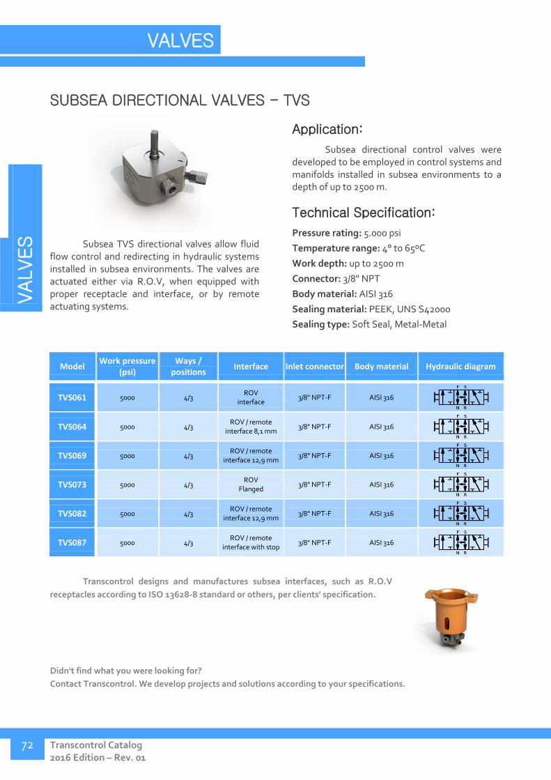
VALVES
Transcontrol Catalog 2016 Edition – Rev. 01
VALVES
72
SUBSEA DIRECTIONAL VALVES - TVS
Subsea TVS directional valves allow fluid flow control and redirecting in hydraulic systems installed in subsea environments. The valves are actuated either via R.O.V, when equipped with proper receptacle and interface, or by remote actuating systems.
Application:
Subsea directional control valves were developed to be employed in control systems and manifolds installed in subsea environments to a depth of up to 2500 m.
Technical Specification:
Pressure rating: 5.000 psi
Temperature range: 4° to 65ºC
Work depth: up to 2500 m
Connector: 3/8" NPT
Body material: AISI 316
Sealing material: PEEK, UNS S42000
Sealing type: Soft Seal, Metal-Metal
Model Work pressure
(psi) Ways /
positions Interface Inlet connector Body material Hydraulic diagram
TVS061 5000 4/3 ROV
interface 3/8" NPT-F AISI 316
TVS064 5000 4/3 ROV / remote
interface 8,1 mm 3/8" NPT-F AISI 316
TVS069 5000 4/3 ROV / remote
interface 12,9 mm 3/8" NPT-F AISI 316
TVS073 5000 4/3 ROV
Flanged 3/8" NPT-F AISI 316
TVS082 5000 4/3 ROV / remote
interface 12,9 mm 3/8" NPT-F AISI 316
TVS087 5000 4/3 ROV / remote
interface with stop 3/8" NPT-F AISI 316
Transcontrol designs and manufactures subsea interfaces, such as R.O.V
receptacles according to ISO 13628-8 standard or others, per clients' specification.
Didn't find what you were looking for?
Contact Transcontrol. We develop projects and solutions according to your specifications.
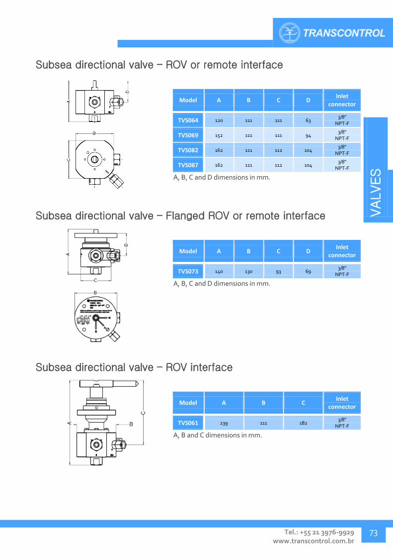
VALVES
Tel.: +55 21 3976-9929 www.transcontrol.com.br
73
Subsea directional valve – ROV or remote interface
Model A B C D Inlet
connector
TVS064 120 111 111 63 3/8"
NPT-F
TVS069 152 111 111 94 3/8"
NPT-F
TVS082 162 111 112 104 3/8"
NPT-F
TVS087 162 111 112 104 3/8"
NPT-F
A, B, C and D dimensions in mm.
Subsea directional valve – Flanged ROV or remote interface
Model A B C D Inlet
connector
TVS073 140 130 93 69 3/8"
NPT-F
A, B, C and D dimensions in mm.
Subsea directional valve – ROV interface
Model A B C Inlet
connector
TVS061 239 111 182 3/8"
NPT-F
A, B and C dimensions in mm.

VALVES
Transcontrol Catalog 2016 Edition – Rev. 01
VALVES
74
PILOTED DIRECTIONAL VALVES - THM
The THM line of pneumatic or manually actuated valves has been developed to allow fast and reliable switching between multiple input lines, employed in hydro-pneumatic systems.
Application:
Onshore and offshore hydraulic panels and units equipped with a pneumatic control line.
Technical Specification:
Pressure rating: up to 10.000 psi
Pilot pressure range: 30 to 150 psi
Temperature range: 4° to 65ºC
Connector: 1/4", 3/8", 1/2" NPT
Pilot connector: 1/4", 3/8" NPT
Body material: AISI 316
Diaphragm material: Buna N Shore A 70
Sealing type: Metal-Metal
Model Work
pressure (psi)
Actuation pressure
(psi)
Inlet connector
Outlet connector
Drain connector
Pilot connector
Body material
Hydraulic diagram
THM001 5000 30-150 1/4" NPT-F 1/4" NPT-F 1/4" NPT-F 1/4" NPT-F AISI 316
THM002 5000 50-150 1/4" NPT-F 1/4" NPT-F 1/4" NPT-F 1/4" NPT-F AISI 316
THM003 10000 30-150 3/8" NPT-F 3/8" NPT-F 3/8" NPT-F 3/8" NPT-F AISI 316
THM004 10000 30-150 1/4" NPT-F 1/4" NPT-F 1/4" NPT-F 1/4" NPT-F AISI 316
THM005 5000 30-150 3/8" NPT-F 3/8" NPT-F 3/8" NPT-F 1/4" NPT-F AISI 316
THM006 10000 30-150 3/8" NPT-F 3/8" NPT-F 3/8" NPT-F 1/4" NPT-F AISI 316
THM007 10000 30-150 1/2" NPT-F 1/2" NPT-F 1/2" NPT-F 3/8" NPT-F AISI 316
Didn't find what you were looking for?
Contact Transcontrol. We develop projects and solutions according to your specifications.
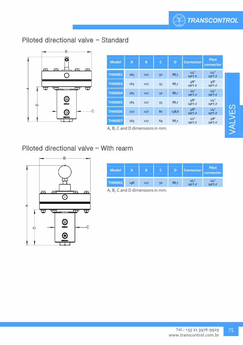
VALVES
Tel.: +55 21 3976-9929 www.transcontrol.com.br
75
Piloted directional valve - Standard
Model A B C D Connector Pilot
connector
THM001 165 127 50 88,7 1/4"
NPT-F 1/4"
NPT-F
THM003 165 127 55 88,7 3/8"
NPT-F 3/8"
NPT-F
THM004 165 127 50 88,7 1/4"
NPT-F 1/4"
NPT-F
THM005 165 127 55 88,7 3/8"
NPT-F 1/4"
NPT-F
THM006 227 127 80 138,6 3/8"
NPT-F 1/4"
NPT-F
THM007 165 127 69 88,7 1/2"
NPT-F 3/8"
NPT-F
A, B, C and D dimensions in mm.
Piloted directional valve – With rearm
Model A B C D Connector Pilot
connector
THM002 198 127 50 88,7 1/4"
NPT-F 1/4"
NPT-F
A, B, C and D dimensions in mm.
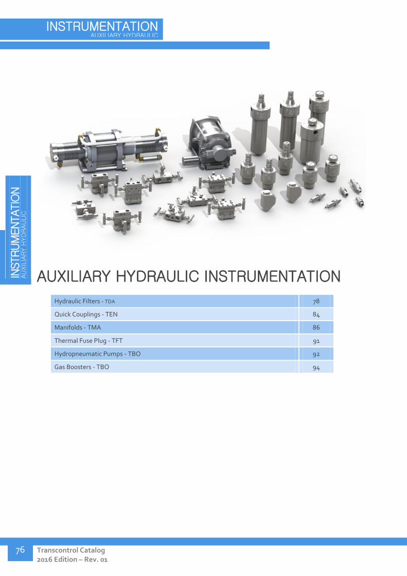
IN
STRUM
ENTATIO
N
AU
XIL
IARY H
YD
RAU
LIC
Transcontrol Catalog 2016 Edition – Rev. 01
INSTRUMENTATION AUXILIARY HYDRAULIC
76
AUXILIARY HYDRAULIC INSTRUMENTATION
Hydraulic Filters - TDA 78
Quick Couplings - TEN 84
Manifolds - TMA 86
Thermal Fuse Plug - TFT 91
Hydropneumatic Pumps - TBO 92
Gas Boosters - TBO 94
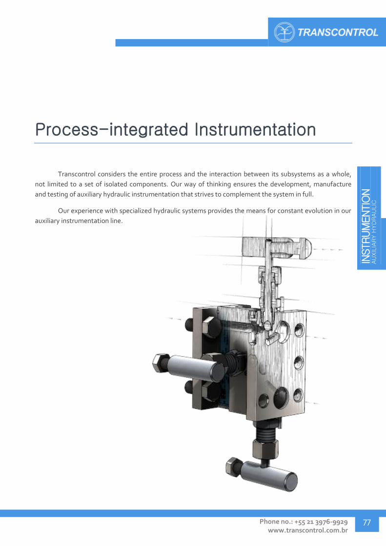
INSTRUM
ENTIO
N
AU
XIL
IARY H
YD
RAU
LIC
Phone no.: +55 21 3976-9929 www.transcontrol.com.br
77
Process-integrated Instrumentation
Transcontrol considers the entire process and the interaction between its subsystems as a whole,
not limited to a set of isolated components. Our way of thinking ensures the development, manufacture
and testing of auxiliary hydraulic instrumentation that strives to complement the system in full.
Our experience with specialized hydraulic systems provides the means for constant evolution in our
auxiliary instrumentation line.

IN
STRUM
ENTATIO
N
AU
XIL
IARY H
YD
RAU
LIC
Transcontrol Catalog 2016 Edition – Rev. 01
INSTRUMENTATION AUXILIARY HYDRAULIC
78
HYDRAULIC FILTERS - TDA
Hydraulic filters are essential components that, when part of a hydraulic system, have the function of guaranteeing the correct fluid cleanliness. By ensuring that the system has a correctly sized filtering setup many faults such as low performance, clogging, excessive wear and premature breakage can be avoided.
Transcontrol designs hydraulic filters for both suction and pressure lines, in various models and configurations.
Application:
Indicated in most hydraulic systems, especially in more sensitive systems where maintaining a minimum fluid cleanliness level is recommended.
Technical Specification:
Pressure rating: up to 10.000 psi
Temperature range: 4° to 65ºC
Connectors: 1/4", 3/8", 1/2", 3/4", 2" NPT
Filtering element: 3, 5, 10, 20, 40, 80, 125, 180 μm.
Body material: AISI 316, AISI 316L, UNS S32750 superduplex, ASTM A-36
Filtering element material: AISI 316, AISI 304, fiberglass
Model Type Work pressure
(psi) Filtering element
(μm) Connector Body material
Filtering element material
TDA002 Compact 5000 40 3/8" NPT-F AISI 316L AISI 316
TDA003 Compact 5000 10 3/8" NPT-F AISI 316L AISI 316
TDA005 Compact 5000 10 3/8" NPT-F (ÂNGULO)
AISI 316L AISI 316
TDA006 Compact 5000 40 3/8" NPT-F (ÂNGULO)
AISI 316L AISI 316
TDA012 Compact 5000 10 1/2" NPT-F AISI 316L AISI 316
TDA046 Compact 15000 10 1/4" NPT-F UNS S32750 AISI 316
TDA004 Compact w/
vacuum gauge Suction 10 3/8" NPT-F AISI 316L AISI 316
TDA009 Compact w/
vacuum gauge Suction 40 3/8" NPT-F AISI 316L AISI 316
TDA017 Simple with visual
indicator 1000 125 3/4" NPT-F AISI 316L AISI 316
TDA019 Simple with visual
indicator 5000 40 3/4" NPT-F AISI 316L AISI 316
TDA022 Simple with visual
indicator 5000 10 3/4" NPT-F AISI 316L AISI 316
TDA026 Simple with visual
indicator 5000 10 3/4" NPT-F AISI 316L AISI 316
TDA027 Simple with visual
indicator 5000 125 3/4" NPT-F AISI 316L AISI 316
TDA028 Simple with visual
indicator 1000 40 3/4" NPT-F AISI 316L AISI 316
TDA029 Simple with visual
indicator 5000 40 3/4" NPT-F AISI 316L AISI 316
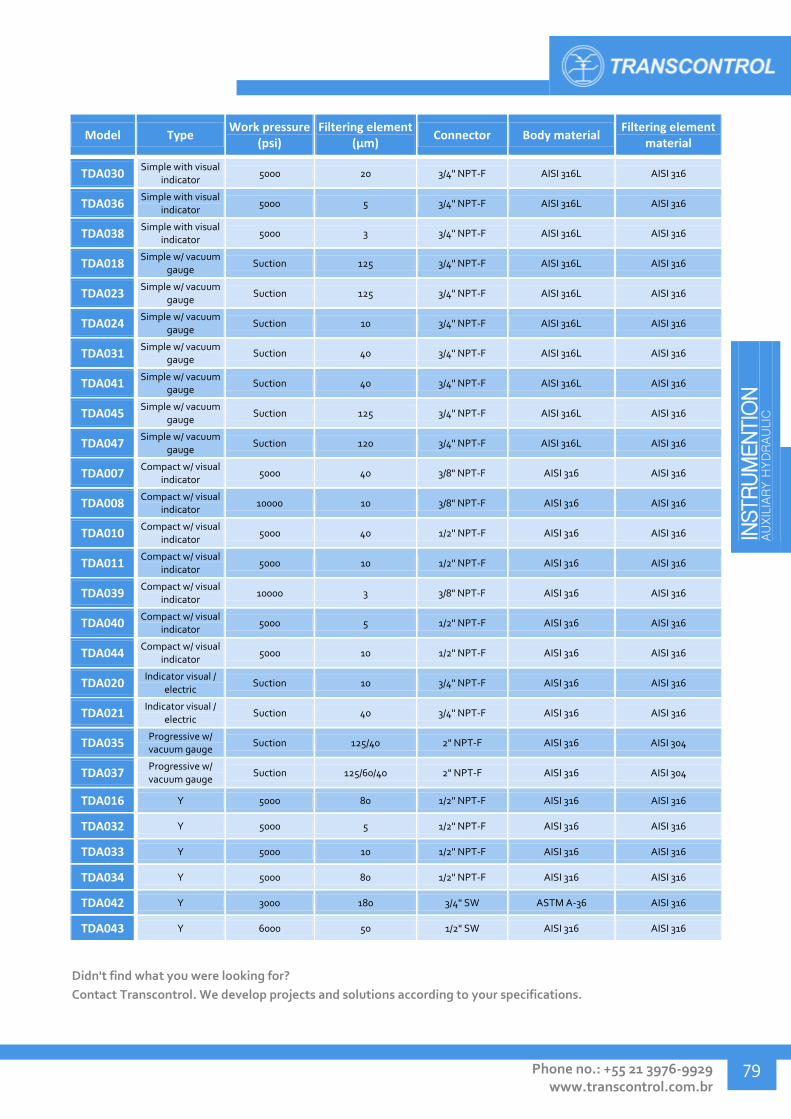
INSTRUM
ENTIO
N
AU
XIL
IARY H
YD
RAU
LIC
Phone no.: +55 21 3976-9929 www.transcontrol.com.br
79
Model Type Work pressure
(psi) Filtering element
(μm) Connector Body material
Filtering element material
TDA030 Simple with visual
indicator 5000 20 3/4" NPT-F AISI 316L AISI 316
TDA036 Simple with visual
indicator 5000 5 3/4" NPT-F AISI 316L AISI 316
TDA038 Simple with visual
indicator 5000 3 3/4" NPT-F AISI 316L AISI 316
TDA018 Simple w/ vacuum
gauge Suction 125 3/4" NPT-F AISI 316L AISI 316
TDA023 Simple w/ vacuum
gauge Suction 125 3/4" NPT-F AISI 316L AISI 316
TDA024 Simple w/ vacuum
gauge Suction 10 3/4" NPT-F AISI 316L AISI 316
TDA031 Simple w/ vacuum
gauge Suction 40 3/4" NPT-F AISI 316L AISI 316
TDA041 Simple w/ vacuum
gauge Suction 40 3/4" NPT-F AISI 316L AISI 316
TDA045 Simple w/ vacuum
gauge Suction 125 3/4" NPT-F AISI 316L AISI 316
TDA047 Simple w/ vacuum
gauge Suction 120 3/4" NPT-F AISI 316L AISI 316
TDA007 Compact w/ visual
indicator 5000 40 3/8" NPT-F AISI 316 AISI 316
TDA008 Compact w/ visual
indicator 10000 10 3/8" NPT-F AISI 316 AISI 316
TDA010 Compact w/ visual
indicator 5000 40 1/2" NPT-F AISI 316 AISI 316
TDA011 Compact w/ visual
indicator 5000 10 1/2" NPT-F AISI 316 AISI 316
TDA039 Compact w/ visual
indicator 10000 3 3/8" NPT-F AISI 316 AISI 316
TDA040 Compact w/ visual
indicator 5000 5 1/2" NPT-F AISI 316 AISI 316
TDA044 Compact w/ visual
indicator 5000 10 1/2" NPT-F AISI 316 AISI 316
TDA020 Indicator visual /
electric Suction 10 3/4" NPT-F AISI 316 AISI 316
TDA021 Indicator visual /
electric Suction 40 3/4" NPT-F AISI 316 AISI 316
TDA035 Progressive w/ vacuum gauge
Suction 125/40 2" NPT-F AISI 316 AISI 304
TDA037 Progressive w/ vacuum gauge
Suction 125/60/40 2" NPT-F AISI 316 AISI 304
TDA016 Y 5000 80 1/2" NPT-F AISI 316 AISI 316
TDA032 Y 5000 5 1/2" NPT-F AISI 316 AISI 316
TDA033 Y 5000 10 1/2" NPT-F AISI 316 AISI 316
TDA034 Y 5000 80 1/2" NPT-F AISI 316 AISI 316
TDA042 Y 3000 180 3/4" SW ASTM A-36 AISI 316
TDA043 Y 6000 50 1/2" SW AISI 316 AISI 316
Didn't find what you were looking for?
Contact Transcontrol. We develop projects and solutions according to your specifications.

IN
STRUM
ENTATIO
N
AU
XIL
IARY H
YD
RAU
LIC
Transcontrol Catalog 2016 Edition – Rev. 01
INSTRUMENTATION AUXILIARY HYDRAULIC
80
Filter - Compact
Model A B C Inlet
connector
TDA002 111 82 61 3/8" NPT-F
TDA003 111 82 61 3/8" NPT-F
TDA005 111 82 61 3/8" NPT-F
(angle)
TDA006 111 82 61 3/8" NPT-F
(angle)
TDA012 109 82 61 1/2" NPT-F
TDA046 115 97 68 1/4" NPT-F
A, B and C dimensions in mm.
Filter – Compact, suction, with vacuum gauge
Model A B C Inlet
connector
TDA004 142 82 61 3/8" NPT-F
TDA009 164 82 61 3/8" NPT-F
A, B and C dimensions in mm.
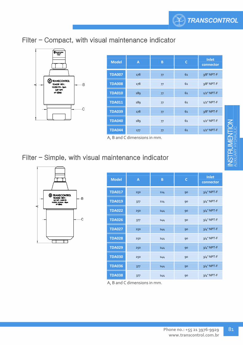
INSTRUM
ENTIO
N
AU
XIL
IARY H
YD
RAU
LIC
Phone no.: +55 21 3976-9929 www.transcontrol.com.br
81
Filter – Compact, with visual maintenance indicator
Model A B C Inlet
connector
TDA007 178 77 61 3/8" NPT-F
TDA008 178 77 61 3/8" NPT-F
TDA010 189 77 61 1/2" NPT-F
TDA011 189 77 61 1/2" NPT-F
TDA039 178 77 61 3/8" NPT-F
TDA040 189 77 61 1/2" NPT-F
TDA044 177 77 61 1/2" NPT-F
A, B and C dimensions in mm.
Filter – Simple, with visual maintenance indicator
Model A B C Inlet
connector
TDA017 250 114 90 3/4" NPT-F
TDA019 377 114 90 3/4" NPT-F
TDA022 250 144 90 3/4" NPT-F
TDA026 377 144 90 3/4" NPT-F
TDA027 250 144 90 3/4" NPT-F
TDA028 250 144 90 3/4" NPT-F
TDA029 250 144 90 3/4" NPT-F
TDA030 250 144 90 3/4" NPT-F
TDA036 377 144 90 3/4" NPT-F
TDA038 377 144 90 3/4" NPT-F
A, B and C dimensions in mm.

IN
STRUM
ENTATIO
N
AU
XIL
IARY H
YD
RAU
LIC
Transcontrol Catalog 2016 Edition – Rev. 01
INSTRUMENTATION AUXILIARY HYDRAULIC
82
Filter – Simple, suction, with vacuum gauge
Model A B C Inlet
connector
TDA018 270 128 115 3/4" NPT-F
TDA023 213 114 90 3/4" NPT-F
TDA024 213 114 90 3/4" NPT-F
TDA031 232 114 90 3/4" NPT-F
TDA041 339 114 89 3/4" NPT-F
TDA045 339 114 89 3/4" NPT-F
TDA047 213 114 90 3/4" NPT-F
A, B and C dimensions in mm.
Filter – Simple, with electric/visual maintenance indicator
Model A B C Inlet
connector
TDA020 250 99 73 3/4" NPT-F
TDA021 250 99 73 3/4" NPT-F
A, B and C dimensions in mm.
Filter – Suction, double filter progressive, with vacuum gauge
Model A B C Inlet
connector
TDA035 215 183 150 2" NPT-F
A, B and C dimensions in mm.

INSTRUM
ENTIO
N
AU
XIL
IARY H
YD
RAU
LIC
Phone no.: +55 21 3976-9929 www.transcontrol.com.br
83
Filter – Suction, triple filter progressive, with vacuum gauge
Model A B C Inlet
connector
TDA037 215 183 150 2" NPT-F
A, B and C dimensions in mm.
Filter - Y
Model A B Inlet
connector
TDA016 90 89 1/2" NPT-F
TDA032 90 89 1/2" NPT-F
TDA033 90 89 1/2" NPT-F
TDA034 90 89 1/2" NPT-F
TDA042 96 92 3/4" SW
TDA043 96 92 1/2" SW
A, B and C dimensions in mm.

IN
STRUM
ENTATIO
N
AU
XIL
IARY H
YD
RAU
LIC
Transcontrol Catalog 2016 Edition – Rev. 01
INSTRUMENTATION AUXILIARY HYDRAULIC
84
QUICK COUPLINGS - TEN
The TEN quick coupling valves are special connector-valves that allow fast and safe connection and disconnection of hoses and other line components, manually and without use of tools, blocking the passage of fluid automatically when disconnected.
Application:
Indicated for hydraulic systems or testing setups, where frequent connection and disconnection of equipment is necessary.
Technical Specification:
Pressure rating: up to 8.000 psi
Temperature range: 4° to 65ºC
Connectors: 1/4", 3/8" NPT, 1/4" JIC
Body material: AISI 316, UNS S32760 duplex
Stem material: AISI 316, UNS S32760 duplex
Locking Ball material: AISI 316, Inconel
Spring material: AISI 302
Sealing type: Soft Seal
Model Work pressure
(psi) Inlet connector Outlet connector Body material Spring material
TEN001 4000 1/4" NPT-F 1/4" NPT-M AISI 316 AISI 302
TEN002 8000 1/4" NPT-F 1/4" NPT-M AISI 316 AISI 302
TEN003 8000 1/4" NPT-F 1/4" NPT-F AISI 316 AISI 302
TEN004 8000 1/4" NPT-F 1/4" NPT-F AISI 316 AISI 302
TEN005 8000 3/8” NPT-F 3/8” NPT-F AISI 316 AISI 302
TEN006 8000 3/8” NPT-M 3/8” NPT-F AISI 316 AISI 302
TEN007 8000 3/8” NPT-M 1/4" JIC AISI 316 AISI 316
TEN008 8000 1/4" OD/DA 1/4" NPT-M AISI 316 AISI 316
TEN009 5000 3/8” NPT-M 3/8” NPT-F AISI 316 AISI 302
TEN011 10000 3/8" NPT-M 1/4" JIC UNS S32760 AISI 302
TEN012 10000 1/4" NPT-F 1/4" NPT-M UNS S32760 AISI 302
TEN013 20000 1/4" NPT-F 1/4" NPT-F UNS S17400 AISI 302
TEN014 10000 3/8" NPT-F 3/8" NPT-F UNS S32760 AISI 302
TEN015 5000 1/4" JIC 3/8" NPT-M AISI 316 AISI 302
TEN016 15000 1/4" NPT-M 1/4" NPT-F UNS S32760 -
Didn't find what you were looking for?
Contact Transcontrol. We develop projects and solutions according to your specifications.

INSTRUM
ENTIO
N
AU
XIL
IARY H
YD
RAU
LIC
Phone no.: +55 21 3976-9929 www.transcontrol.com.br
85
Quick Coupling - NPT x NPT connector
Model A B C Inlet
connector Outlet
connector
TEN001 85 60.8 50.5 1/4"
NPT - F 1/4"
NPT-M
TEN002 85 60.8 50.5 1/4"
NPT - F 1/4"
NPT-M
TEN003 74.9 56 40.9 1/4"
NPT-F 1/4"
NPT - F
TEN004 74.9 56 40.9 1/4"
NPT-F 1/4"
NPT - F
TEN005 119 71.5 61 3/8”
NPT-F 3/8”
NPT-F
TEN006 87.9 69 40.9 3/8”
NPT-M 3/8”
NPT-F
TEN009 129 71.5 71.3 3/8”
NPT-M 3/8”
NPT-F
TEN012 86 56 52 1/4" NPT-F 1/4" NPT-M
TEN013 81 61,5 38,2 1/4" NPT-F 1/4" NPT-F
TEN014 117,2 70,4 61 3/8" NPT-F 3/8" NPT-F
TEN016 77 62,1 42,5 1/4" NPT-M 1/4" NPT-F
A, B and C dimensions in mm.
Quick Coupling – Various connectors
Model A B C Inlet
connector Outlet
connector
TEN007 117 54.1 84.8 3/8”
NPT - M 1/4" JIC
TEN008 123 87,5 56,7 1/4"
OD/DA 1/4"
NPT-M
TEN011 118 54,1 86 3/8" NPT-M 1/4" JIC
TEN015 118 86 54 1/4" JIC 3/8" NPT-M
A, B and C dimensions in mm.

IN
STRUM
ENTATIO
N
AU
XIL
IARY H
YD
RAU
LIC
Transcontrol Catalog 2016 Edition – Rev. 01
INSTRUMENTATION AUXILIARY HYDRAULIC
86
MANIFOLDS - TMA
Manifold valves allow a more compact, safe and reliable and specialized instrumentation setup, by providing a valve system to enable instrument isolation, draining and other functions. Manifolds are also used to distribute hydraulic supply between many outlets from a single inlet in a controlled way.
Application:
For instrumentation setup, isolation and maintenance, or hydraulic supply distribution.
Technical Specification:
Pressure rating: up to 6.500 Psi
Temperature range: 4° to 65ºC
Connectors: Threaded NPT, flanged
Type of stem: Rotary, non rotary
Types: Planar or biplanar
Body material: AISI 316, carbon steel (other materials, contact us).
Sealing type: Metal-Metal, soft seal
Model Work pressure
(psi) Inlet connector Outlet connector Body material Tipo e material da vedação
TMA001 5000 Flange Flange ASTM A216 GR WCB PTFE with fiberglass
TMA002 5000 1/2" NPT -F 1/2" NPT -F AISI 1020 PTFE with fiberglass
TMA003 5000 1/2" NPT -F 1/2" NPT -F AISI 1020 Ferrule - PTFE
TMA004 6000 Flange Flange AISI 316 PTFE with fiberglass
TMA005 5000 1/2" NPT -F 1/2" NPT -F AISI 316 PTFE with fiberglass
TMA006 5000 1/2" NPT -F 1/2" NPT -F AISI 316 Ferrule - PTFE
TMA007 5000 1/2" NPT -F 1/2" NPT -F AISI 316 Ferrule - PTFE
TMA008 5000 1/2" NPT -F 1/2" NPT -F AISI 1020 Gasket - PTFE
TMA009 5000 1/2" NPT - F 1/2" NPT - F AISI 316 PTFE
TMA010 5000 1/2" NPT- F 1/8” NPT - F AISI 1020 Ferrule - PTFE
TMA011 5000 1/2" NPT- F Flange AISI 1020 PTFE
TMA012 5000 1/2" NPT- F Flange AISI 316 PTFE
TMA014 5000 1/2" NPT- F 1/2" NPT- F AISI 1020 Ferrule - PTFE
TMA015 5000 1/2" NPT -F 1/2" NPT -F AISI 1020 Ferrule - PTFE
TMA018 5000 1/2" NPT- F 1/2" NPT- F AISI 316 Ferrule - Graphite PTFE
TMA019 6000 1/2" NPT - F 1/2" NPT - F AISI 316 PTFE with fiberglass
TMA020 6500 1/2" NPT -F 1/2" NPT - f AISI 316 Gasket - Grafoil
TMA021 6500 1/2" NPT -F 1/2" NPT - f AISI 316 Gasket - PTFE

INSTRUM
ENTIO
N
AU
XIL
IARY H
YD
RAU
LIC
Phone no.: +55 21 3976-9929 www.transcontrol.com.br
87
Model Work pressure
(psi) Inlet connector Outlet connector Body material Tipo e material da vedação
TMA022 6500 1/2" NPT - F 1/2" NPT - F AISI 316 Gasket - Grafoil
TMA023 6000 Flange 1/2" NPT - F AISI 1020 PTFE with fiberglass
TMA025 5000 1/2" BSP 1/8” NPT - f AISI 316 PTFE
TMA026 6500 1/2" NPT - F 1/2" NPT - F AISI 316 Gasket - PTFE
TMA027 3000 1/2" NPT -F 1/2" NPT -F AISI 316 Gasket - PTFE
TMA028 5000 1/2" NPT -F 1/2" NPT -F AISI 1020 Ferrule - Graphite PTFE
TMA029 6500 1/2" NPT - F 1/2" NPT - F AISI 316 Gasket - PTFE
TMA030 6000 Flange Flange AISI 316 PTFE with fiberglass
TMA031 6000 1/2" NPT -F 1/2" NPT - F AISI 316 Ferrule - PTFE
TMA032 6500 1/2" NPT - F 1/2" NPT - F AISI 316 Gasket - PTFE
TMA033 6000 Flange 1/2" NPT -F AISI 316 PTFE with fiberglass
TMA034 6000 1/2" NPT -F 1/2" NPT -F AISI 316 PTFE with fiberglass
TMA035 5000 1/2" NPT -F 1/2" NPT -F AISI 316 PTFE with fiberglass
TMA036 5000 1/2" NPT- F 1/8” NPT - F AISI 316 PTFE
TMA037 6500 1/2" NPT - M 1/2" NPT - F AISI 316 Gasket - PTFE
TMA039 6000 Flange 1/2" NPT -F AISI 316 PTFE with fiberglass
TMA041 6500 1/2" NPT - F Flange AISI 316 PTFE with fiberglass
TMA042 6500 1/2" NPT - F 1/2" NPT - F ASTM A216 GR WCB Gasket - PTFE
Didn't find what you were looking for?
Contact Transcontrol. We develop projects and solutions according to your specifications.

IN
STRUM
ENTATIO
N
AU
XIL
IARY H
YD
RAU
LIC
Transcontrol Catalog 2016 Edition – Rev. 01
INSTRUMENTATION AUXILIARY HYDRAULIC
88
Manifold - 2 way, rotary stem
Model A B C Inlet
connector Outlet
connector
TMA009 162 105 36 1/2"
NPT-F 1/2"
NPT-F
TMA010 162 105 36 1/2"
NPT-F 1/8”
NPT-F
TMA011 99 70 36 1/2"
NPT-F Flange
TMA012 99 70 36 1/2"
NPT-F Flange
TMA014 162 105 36 1/2"
NPT-F 1/2"
NPT-F
TMA018 162 105 36 1/2"
NPT-F 1/2"
NPT-F
TMA025 162 105 36 1/2" BSP 1/8”
NPT-F
TMA036 208 88 63 1/2"
NPT-F 1/8”
NPT-F
A, B and C dimensions in mm.
Manifold – 2 way, non rotary stem
Model A B C D Inlet
connector Outlet
connector
TMA020 86.2 86.2 98 56 1/2"
NPT-F 1/2"
NPT-F
TMA021 86.2 86.2 98 56 1/2"
NPT-F 1/2"
NPT-F
TMA022 86.2 86.2 98 60 1/2"
NPT-F 1/2"
NPT-F
TMA027 86.2 86.2 98 56 1/2"
NPT-F 1/2"
NPT-F
TMA032 86.2 86.2 98 56 1/2"
NPT-F 1/2"
NPT-F
TMA037 86.2 86.2 98 56 1/2"
NPT-M 1/2"
NPT-F
TMA042 86.2 86.2 98 56 1/2"
NPT-F 1/2"
NPT-F
A, B and C dimensions in mm.

INSTRUM
ENTIO
N
AU
XIL
IARY H
YD
RAU
LIC
Phone no.: +55 21 3976-9929 www.transcontrol.com.br
89
Manifold – 3 way
Model A B C D E F G H I Inlet
connector Outlet
connector
TMA001 221 54 86 107 41 58 78 34 17 Flange Flange
TMA002 212 54 86 106 41 58 95 55 38 1/2"
NPT-F 1/2"
NPT-F
TMA003 221 54 96 94 - 32 60 30 14 1/2"
NPT-F 1/2"
NPT-F
TMA004 221 54 86 107 41 58 78 34 17 Flange Flange
TMA005 212 54 86 106 41 58 95 55 38 1/2"
NPT-F 1/2"
NPT-F
TMA006 221 54 98 94 - 32 60 30 14 1/2"
NPT-F 1/2"
NPT-F
TMA015 212 56 84 106 41 58 95 55 38 1/2"
NPT-F 1/2"
NPT-F
TMA019 213 54 95 125 - 32 63 - - 1/2"
NPT-F 1/2"
NPT-F
TMA023 213 54 95 - - - - - - Flange 1/2"
NPT-F
TMA026 203 54 96 86 - 32 62 32 - 1/2"
NPT-F 1/2"
NPT-F
TMA028 221 54 96 94 - 32 60 30 14 1/2"
NPT-F 1/2"
NPT-F
TMA029 203 54 96 86 - 32 62 32 - 1/2"
NPT-F 1/2"
NPT-F
TMA030 221 54 86 107 41 58 78 34 17 Flange Flange
TMA031 221 54 96 94 - 32 60 30 - 1/2"
NPT-F 1/2"
NPT-F
TMA033 213 55 95 - - - - - - Flange 1/2"
NPT-F
TMA039 213 54 95 - - - - - - Flange 1/2"
NPT-F
TMA041 203 54 86 103 41 58 95 55 38 1/2"
NPT-F Flange
A, B, C, D, E, F, G, H e I dimensions in mm.
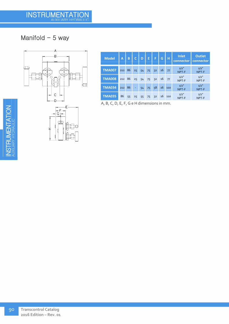
IN
STRUM
ENTATIO
N
AU
XIL
IARY H
YD
RAU
LIC
Transcontrol Catalog 2016 Edition – Rev. 01
INSTRUMENTATION AUXILIARY HYDRAULIC
90
Manifold - 5 way
Model A B C D E F G H Inlet
connector Outlet
connector
TMA007 212 86 25 54 75 32 16 77 1/2"
NPT-F 1/2"
NPT-F
TMA008 212 86 25 54 75 32 16 77 1/2"
NPT-F 1/2"
NPT-F
TMA034 212 86 - 54 75 58 16 110 1/2"
NPT-F 1/2"
NPT-F
TMA035 86 55 25 55 75 32 16 110 1/2"
NPT-F 1/2"
NPT-F
A, B, C, D, E, F, G e H dimensions in mm.
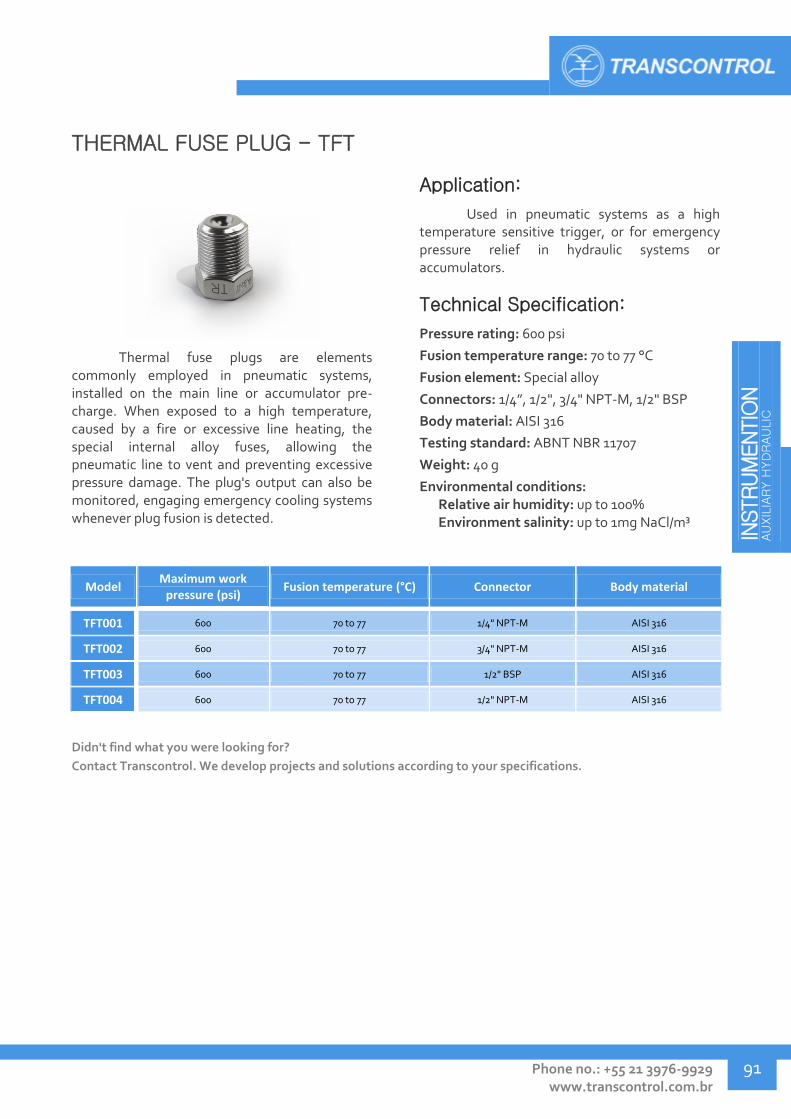
INSTRUM
ENTIO
N
AU
XIL
IARY H
YD
RAU
LIC
Phone no.: +55 21 3976-9929 www.transcontrol.com.br
91
THERMAL FUSE PLUG - TFT
Thermal fuse plugs are elements commonly employed in pneumatic systems, installed on the main line or accumulator pre-charge. When exposed to a high temperature, caused by a fire or excessive line heating, the special internal alloy fuses, allowing the pneumatic line to vent and preventing excessive pressure damage. The plug's output can also be monitored, engaging emergency cooling systems whenever plug fusion is detected.
Application:
Used in pneumatic systems as a high temperature sensitive trigger, or for emergency pressure relief in hydraulic systems or accumulators.
Technical Specification:
Pressure rating: 600 psi
Fusion temperature range: 70 to 77 °C
Fusion element: Special alloy
Connectors: 1/4”, 1/2", 3/4" NPT-M, 1/2" BSP
Body material: AISI 316
Testing standard: ABNT NBR 11707
Weight: 40 g
Environmental conditions: Relative air humidity: up to 100% Environment salinity: up to 1mg NaCl/m³
Model Maximum work
pressure (psi) Fusion temperature (°C) Connector Body material
TFT001 600 70 to 77 1/4" NPT-M AISI 316
TFT002 600 70 to 77 3/4" NPT-M AISI 316
TFT003 600 70 to 77 1/2" BSP AISI 316
TFT004 600 70 to 77 1/2" NPT-M AISI 316
Didn't find what you were looking for?
Contact Transcontrol. We develop projects and solutions according to your specifications.
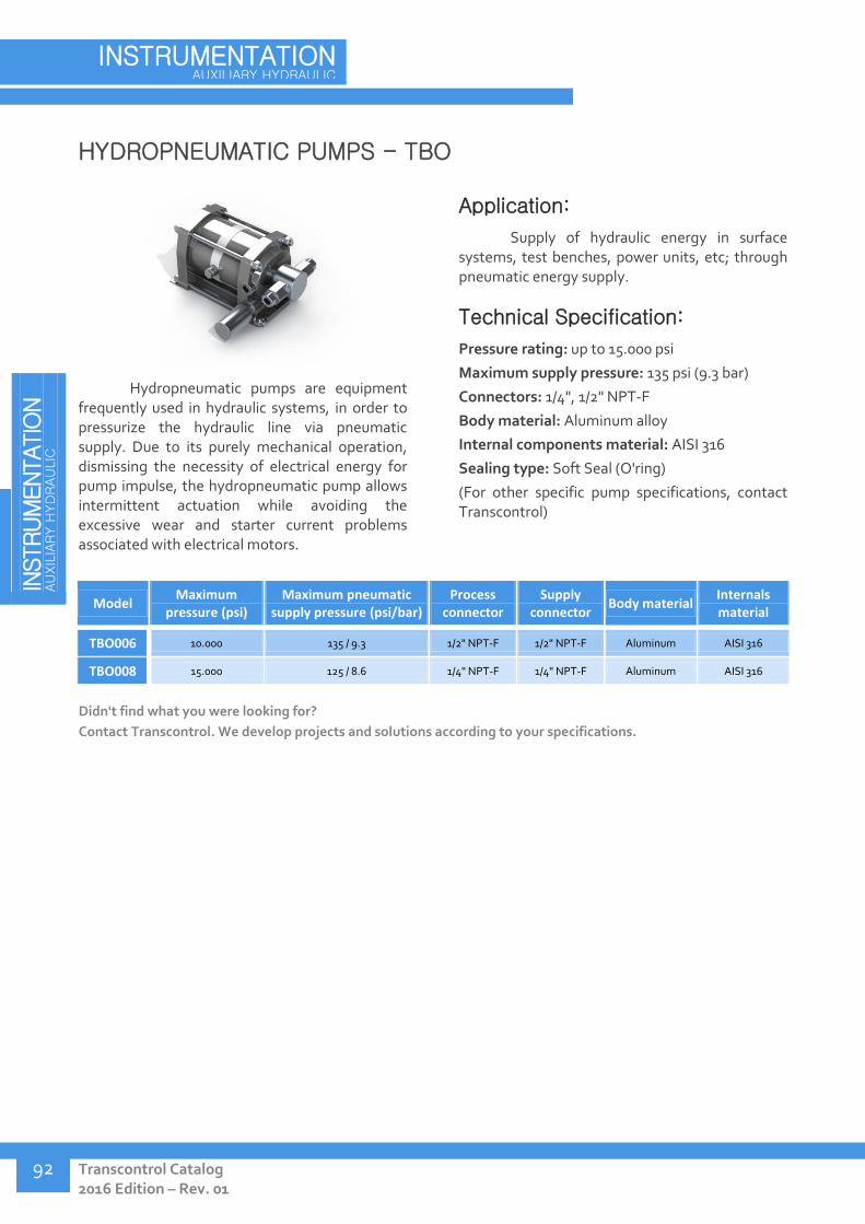
IN
STRUM
ENTATIO
N
AU
XIL
IARY H
YD
RAU
LIC
Transcontrol Catalog 2016 Edition – Rev. 01
INSTRUMENTATION AUXILIARY HYDRAULIC
92
HYDROPNEUMATIC PUMPS - TBO
Hydropneumatic pumps are equipment frequently used in hydraulic systems, in order to pressurize the hydraulic line via pneumatic supply. Due to its purely mechanical operation, dismissing the necessity of electrical energy for pump impulse, the hydropneumatic pump allows intermittent actuation while avoiding the excessive wear and starter current problems associated with electrical motors.
Application:
Supply of hydraulic energy in surface systems, test benches, power units, etc; through pneumatic energy supply.
Technical Specification:
Pressure rating: up to 15.000 psi
Maximum supply pressure: 135 psi (9.3 bar)
Connectors: 1/4", 1/2" NPT-F
Body material: Aluminum alloy
Internal components material: AISI 316
Sealing type: Soft Seal (O'ring)
(For other specific pump specifications, contact Transcontrol)
Model Maximum
pressure (psi) Maximum pneumatic
supply pressure (psi/bar) Process
connector Supply
connector Body material
Internals material
TBO006 10.000 135 / 9.3 1/2" NPT-F 1/2" NPT-F Aluminum AISI 316
TBO008 15.000 125 / 8.6 1/4" NPT-F 1/4" NPT-F Aluminum AISI 316
Didn't find what you were looking for?
Contact Transcontrol. We develop projects and solutions according to your specifications.
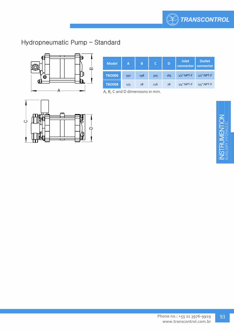
INSTRUM
ENTIO
N
AU
XIL
IARY H
YD
RAU
LIC
Phone no.: +55 21 3976-9929 www.transcontrol.com.br
93
Hydropneumatic Pump – Standard
Model A B C D Inlet
connector Outlet
connector
TBO006 350 198 305 183 1/2" NPT-F 1/2" NPT-F
TBO008 173 78 126 78 1/4" NPT-F 1/4" NPT-F
A, B, C and D dimensions in mm.

IN
STRUM
ENTATIO
N
AU
XIL
IARY H
YD
RAU
LIC
Transcontrol Catalog 2016 Edition – Rev. 01
INSTRUMENTATION AUXILIARY HYDRAULIC
94
GAS BOOSTERS - TBO
In pneumatic or gas pressurization systems, Gas boosters are commonly employed to provide a pressure step-up function or to collect gases from reservoirs whose pressure dropped below a free flow limit, by using external pneumatic supply. The gas booster can also utilize the gas line's own fluid as supply to output it at an increased pressure. Since the gas booster does not require electrical motor for its function, it is specially indicated for intermittent workloads.
Application:
Pneumatic pressure amplification in surface gas systems, test benches, gas injection systems, etc; high cost gas scavenging, via pneumatic supply.
Technical Specification:
Pressure rating: up to 10.000 psi (690 bar)
Supply pressure: 217 to 1000 psi (15 to 69 Bar)
Connectors: 1/4" NPT-F, 1/4" BSP-F
Body material: Aluminum alloy
Internal components material: AISI 316
Supply connector: 1/4" NPT-F, 3/4" BSP-F
Sealing type: Soft Seal (O'ring)
(For other booster specifications, contact Transcontrol)
Model Max pressure
(psi/bar) Max supply pressure
(psi/bar) Process
connector Supply
connector Body material
Internals material
TBO004 10.000/690 1000/69 1/4" BSP-F 3/4" BSP-F Aluminum AISI 316
TBO010 260/18 145/10 1/4" NPT-F 1/4" NPT-F Aluminum AISI 316
Didn't find what you were looking for?
Contact Transcontrol. We develop projects and solutions according to your specifications.

INSTRUM
ENTIO
N
AU
XIL
IARY H
YD
RAU
LIC
Phone no.: +55 21 3976-9929 www.transcontrol.com.br
95
Gas Booster – Standard
Model A B C Inlet
connector Outlet
connector
TBO004 645 201 310 1/4" BSP-F 1/4" BSP-F
TBO010 650 205 165 1/4" NPT-F 1/4" NPT-F
A, B and C dimensions in mm.

TR
AN
SM
ITTER
S
AN
D D
ATA A
CQ
UIS
ITIO
N
Transcontrol Catalog 2016 Edition – Rev. 01
TRANSMITTERS AND DATA ACQUISITION
96
TRANSMITTERS AND DATA ACQUISITION
Pressure and Temperature Transmitters – TPT 98
Permanent Downhole Gauge - PDG 106
Downhole Gauge- TTP 110
Coaxial Electrical Cable Splice - TEE 112
V-Cone Flow Meter - TMV 114
IWIS / Universal PDG Interface Card- TLE 116
Signal Acquisition System (SAS) - TLE 117
Portable Signal Acquisition System (SASP) - TLE 118
Mobile Subsea Signal Acquisition System (SSAS) - TSI 119
Independent Subsea Signal Acquisition System (SASMI) - TSI 120
Compact Independent Subsea Signal Acquisition System (SASMIcIr) - TSI 121
Subsea Electrical Monitoring System - TSE 122

TR
AN
SM
ITTER
S
AN
D D
ATA A
CQ
UIS
ITIO
N
Phone no.: +55 21 3976-9929 www.transcontrol.com.br
97
Complete Solutions in Acquisition and
Monitoring Systems
As the monitoring and control processes of platform and chemical processing plants become
increasingly sophisticated, more precision and reliability in rigorous environments is demanded.
Through our ample experience in the development of transmitters and data acquisition systems, we
constantly promote innovation and progression of Brazilian technology, in order to fulfill the constantly
evolving demands of the oil & gas industry.
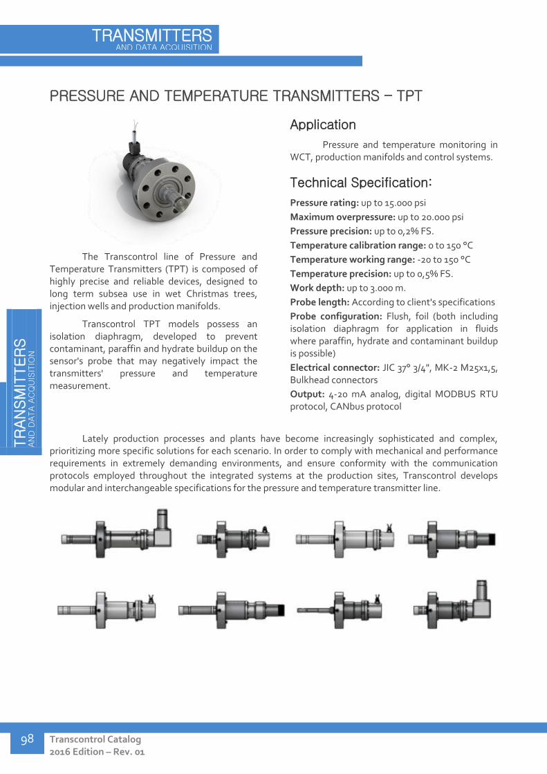
TR
AN
SM
ITTER
S
AN
D D
ATA A
CQ
UIS
ITIO
N
Transcontrol Catalog 2016 Edition – Rev. 01
TRANSMITTERS AND DATA ACQUISITION
98
PRESSURE AND TEMPERATURE TRANSMITTERS – TPT
The Transcontrol line of Pressure and Temperature Transmitters (TPT) is composed of highly precise and reliable devices, designed to long term subsea use in wet Christmas trees, injection wells and production manifolds.
Transcontrol TPT models possess an isolation diaphragm, developed to prevent contaminant, paraffin and hydrate buildup on the sensor's probe that may negatively impact the transmitters' pressure and temperature measurement.
Application
Pressure and temperature monitoring in WCT, production manifolds and control systems.
Technical Specification:
Pressure rating: up to 15.000 psi
Maximum overpressure: up to 20.000 psi
Pressure precision: up to 0,2% FS.
Temperature calibration range: 0 to 150 °C
Temperature working range: -20 to 150 °C
Temperature precision: up to 0,5% FS.
Work depth: up to 3.000 m.
Probe length: According to client's specifications
Probe configuration: Flush, foil (both including isolation diaphragm for application in fluids where paraffin, hydrate and contaminant buildup is possible)
Electrical connector: JIC 37° 3/4", MK-2 M25x1,5, Bulkhead connectors
Output: 4-20 mA analog, digital MODBUS RTU protocol, CANbus protocol
Lately production processes and plants have become increasingly sophisticated and complex, prioritizing more specific solutions for each scenario. In order to comply with mechanical and performance requirements in extremely demanding environments, and ensure conformity with the communication protocols employed throughout the integrated systems at the production sites, Transcontrol develops modular and interchangeable specifications for the pressure and temperature transmitter line.
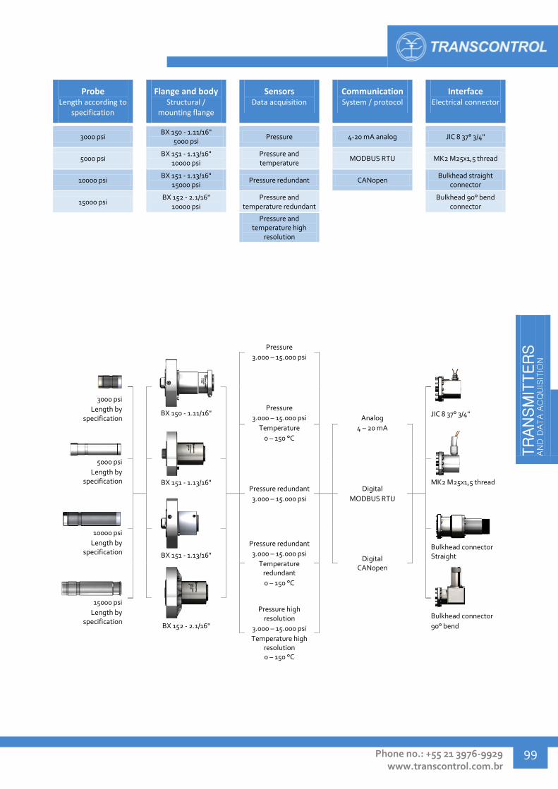
TR
AN
SM
ITTER
S
AN
D D
ATA A
CQ
UIS
ITIO
N
Phone no.: +55 21 3976-9929 www.transcontrol.com.br
99
Probe Length according to
specification
Flange and body Structural /
mounting flange
Sensors Data acquisition
Communication System / protocol
Interface Electrical connector
3000 psi BX 150 - 1.11/16"
5000 psi Pressure 4-20 mA analog JIC 8 37° 3/4"
5000 psi BX 151 - 1.13/16"
10000 psi
Pressure and temperature
MODBUS RTU MK2 M25x1,5 thread
10000 psi BX 151 - 1.13/16"
15000 psi Pressure redundant CANopen
Bulkhead straight connector
15000 psi BX 152 - 2.1/16"
10000 psi
Pressure and temperature redundant
Bulkhead 90° bend
connector
Pressure and
temperature high resolution
2
Pressure
3.000 – 15.000 psi
3000 psi
Length by specification
BX 150 - 1.11/16"
JIC 8 37° 3/4" Pressure
3.000 – 15.000 psi
Temperature
0 – 150 °C
Analog
4 – 20 mA
5000 psi
Length by specification
BX 151 - 1.13/16"
MK2 M25x1,5 thread
Pressure redundant
3.000 – 15.000 psi
Digital
MODBUS RTU
10000 psi
Length by specification
BX 151 - 1.13/16"
Bulkhead connector Straight
Pressure redundant
3.000 – 15.000 psi
Temperature redundant
0 – 150 °C
Digital CANopen
15000 psi
Length by specification
BX 152 - 2.1/16"
Bulkhead connector
90° bend
Pressure high
resolution
3.000 – 15.000 psi
Temperature high resolution 0 – 150 °C

TR
AN
SM
ITTER
S
AN
D D
ATA A
CQ
UIS
ITIO
N
Transcontrol Catalog 2016 Edition – Rev. 01
TRANSMITTERS AND DATA ACQUISITION
100
Model
Type of transmitter (Pressure /
Temp.)
Work pressure
(psi)
Temp. calibration range (°C)
Temp, work range (°C)
Flange interface
Electrical connector
Output Body / Probe
material
TPT007 P. and T. High
Resolution 5000 0° a 100° -10° a 150°
API 6A - BX 151 - 1.13/16" - 10000 psi
JIC 8 37° 3/4" Digital MODBUS
RTU AISI 316L / Inconel
TPT008 P. Flush 2900 0° a 100° -10° a 120° API 6A - BX 151 -
1.13/16" - 10000 psi Bulkhead 90°
bend Analog 4-20 mA
AISI 316L / AISI 316L
TPT012 P. and T. Flush 5000 0° a 100° -10° a 120° API 6A - BX 151 -
1.13/16" - 10000 psi JIC 8 37° 3/4" Analog 4-20 mA AISI 316L / Inconel
TPT013 P. and T. Flush 2900 0° a 125° -10° a 125° API 6A - BX 151 -
1.13/16" - 10000 psi Bulkhead 90°
bend Analog 4-20 mA
AISI 316L / AISI 316L
TPT014 P. and T. Flush 3000 0° a 100° -10° a 120° API 6A - BX 151 -
1.13/16" - 10000 psi JIC 8 37° 3/4" Analog 4-20 mA AISI 316L / Inconel
TPT015 P. and T. Flush 5000 0° a 100° -10° a 120° API 6A - BX 151 -
1.13/16" - 10000 psi JIC 8 37° 3/4" Analog 4-20 mA
Superduplex / Inconel
TPT016 P. Flush 5000 0° a 100° -10° a 120° API 6A - BX 151 -
1.13/16" - 10000 psi JIC 8 37° 3/4" Analog 4-20 mA AISI 316L / Inconel
TPT017 P. and T. Flush 5000 0° a 100° -10° a 120° API 6A - BX 151 -
1.13/16" - 10000 psi JIC 8 37° 3/4" Analog 4-20 mA
Superduplex / Inconel
TPT028 P. and T. High
Resolution 10000 0° a 120° -10° a 150°
API 6A - BX 151 - 1.13/16" - 10000 psi
JIC 8 37° 3/4" Digital MODBUS
RTU Superduplex /
Inconel
TPT029 P. Flush 5000 0° a 100° -10° a 120° API 6A - BX 151 -
1.13/16" - 10000 psi JIC 8 37° 3/4" Analog 4-20 mA
Superduplex / Inconel
TPT030 P. and T. Flush 5000 0° a 100° -10° a 120° API 6A - BX 151 -
1.13/16" - 10000 psi MK2 M25x1,5
thread Analog 4-20 mA AISI 316L / Inconel
TPT031 P. Flush 5000 0° a 100° -10° a 120° API 6A - BX 151 -
1.13/16" - 10000 psi MK2 M25x1,5
thread Analog 4-20 mA AISI 316L / Inconel
TPT032 P. and T. High
Resolution 5000 0° a 100° -10° a 150°
API 6A - BX 151 - 1.13/16" - 10000 psi
JIC 8 37° 3/4" Digital MODBUS
RTU Superduplex /
Inconel
TPT033 P. and T. Flush 10000 0° a 120° -10° a 120° API 6A - BX 151 -
1.13/16" - 10000 psi JIC 8 37° 3/4" Analog 4-20 mA
Superduplex / Inconel
TPT034 T. - 0° a 100° -10° a 120° API 6A - BX 151 -
1.13/16" - 10000 psi JIC 8 37° 3/4" Analog 4-20 mA
Superduplex / Inconel
TPT035 P. and T. High
Resolution 10000 0° a 150° -10° a 150°
API 6A - BX 151 - 1.13/16" - 10000 psi
JIC 8 37° 3/4" Digital MODBUS
RTU Superduplex /
Inconel
TPT036 P. and T. High
Resolution 5000 0° a 150° -10° a 150°
API 6A - BX 151 - 1.13/16" - 10000 psi
JIC 8 37° 3/4" Digital MODBUS
RTU AISI 316L / Inconel
TPT040 P. Flush 10000 0° a 120° -10° a 120° API 6A - BX 151 -
1.13/16" - 10000 psi JIC 8 37° 3/4" Analog 4-20 mA
Superduplex / Inconel
TPT041 P. and T. High
Resolution 5000 0° a 100° -10° a 150°
API 6A - BX 151 - 1.13/16" - 10000 psi
MK2 M25x1,5 thread
Digital MODBUS RTU
Superduplex / Inconel
TPT042 P. Flush 5000 0° a 100° -10° a 120° API 6A - BX 151 -
1.13/16" - 10000 psi MK2 M25x1,5
thread Analog 4-20 mA
Superduplex / Inconel
TPT043 P. and T. High
Resolution 10000 0° a 150° -10° a 150°
API 6A - BX 151 - 1.13/16" - 10000 psi
MK2 M25x1,5 thread
Digital MODBUS RTU
Superduplex / Inconel
TPT044 P. Flush 10000 0° a 120° -10° a 120° API 6A - BX 151 -
1.13/16" - 10000 psi MK2 M25x1,5
thread Analog 4-20 mA
Superduplex / Inconel
TPT045 P. and T. Flush 10000 0° a 120° -10° a 120° API 6A - BX 151 -
1.13/16" - 10000 psi MK2 M25x1,5
thread Analog 4-20 mA
Superduplex / Inconel
TPT046 P. Flush 5000 0° a 100° -10° a 120° API 6A - BX 151 -
1.13/16" - 10000 psi JIC 8 37° 3/4" Analog 4-20 mA
Superduplex / Inconel
TPT047 P. Flush 3000 0° a 100° -10° a 120° API 6A - BX 151 -
1.13/16" - 10000 psi JIC 8 37° 3/4" Analog 4-20 mA
Superduplex / Inconel
TPT048 P. Flush 5000 0° a 100° -10° a 120° API 6A - BX 151 -
1.13/16" - 10000 psi Bulkhead 90°
bend Analog 4-20 mA
Superduplex / Inconel
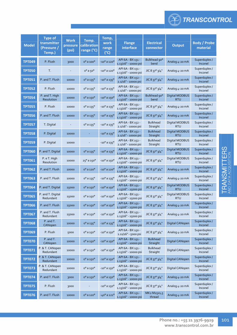
TR
AN
SM
ITTER
S
AN
D D
ATA A
CQ
UIS
ITIO
N
Phone no.: +55 21 3976-9929 www.transcontrol.com.br
101
Model
Type of transmitter (Pressure /
Temp.)
Work pressure
(psi)
Temp. calibration range (°C)
Temp, work range (°C)
Flange interface
Electrical connector
Output Body / Probe
material
TPT049 P. Flush 3000 0° a 100° -10° a 120° API 6A - BX 151 -
1.13/16" - 10000 psi Bulkhead 90°
bend Analog 4-20 mA
Superduplex / Inconel
TPT050 T. - 0° a 50° -10° a 120° API 6A - BX 151 -
1.13/16" - 10000 psi JIC 8 37° 3/4" Analog 4-20 mA
Superduplex / Inconel
TPT051 P. and T. Flush 10000 0° a 135° -10° a 135° API 6A - BX 152 -
2.1/16" - 10000 psi JIC 8 37° 3/4" Analog 4-20 mA
Superduplex / Inconel
TPT052 P. Flush 10000 0° a 135° -10° a 135° API 6A - BX 152 -
2.1/16" - 10000 psi JIC 8 37° 3/4" Analog 4-20 mA
Superduplex / Inconel
TPT054 P. and T. High
Resolution 10000 0° a 150° -10° a 150°
API 6A - BX 151 - 1.13/16" - 10000 psi
Bulkhead 90° bend
Digital MODBUS RTU
Superduplex / Inconel
TPT055 P. Flush 10000 0° a 135° -10° a 135° API 6A - BX 151 -
1.13/16" - 10000 psi JIC 8 37° 3/4" Analog 4-20 mA
Superduplex / Inconel
TPT056 P. and T. Flush 10000 0° a 135° -10° a 135° API 6A - BX 151 -
1.13/16" - 10000 psi JIC 8 37° 3/4" Analog 4-20 mA
Superduplex / Inconel
TPT057 T. Digital - 0° a 135° -10° a 135° API 6A - BX 152 -
2.1/16" - 10000 psi Bulkhead Straight
Digital MODBUS RTU
Superduplex / Inconel
TPT058 P. Digital 10000 - -10° a 135° API 6A - BX 152 -
2.1/16" - 10000 psi Bulkhead Straight
Digital MODBUS RTU
Superduplex / Inconel
TPT059 P. Digital 10000 - -10° a 135° API 6A - BX 152 -
2.1/16" - 10000 psi Bulkhead Straight
Digital MODBUS RTU
Superduplex / Inconel
TPT060 P. and T. Digital 10000 0° a 135° -10° a 135° API 6A - BX 151 -
1.13/16" - 10000 psi JIC 8 37° 3/4"
Digital MODBUS RTU
Superduplex / Inconel
TPT061 P. e T. High Resolution
10000 25° a 150° -10° a 150° API 6A - BX 151 -
1.13/16" - 10000 psi JIC 8 37° 3/4"
Digital MODBUS RTU
Superduplex / Inconel
TPT062 P. and T. Flush 10000 0° a 120° -10° a 120° API 6A - BX 151 -
1.13/16" - 10000 psi JIC 8 37° 3/4" Analog 4-20 mA
Superduplex / Inconel
TPT063 P. and T. Flush 10000 0° a 135° -10° a 135° API 6A - BX 151 -
1.13/16" - 10000 psi JIC 8 37° 3/4" Analog 4-20 mA
Superduplex / Inconel
TPT064 P. and T. Digital 15000 0° a 150° -10° a 150° API 6A - BX 151 -
1.13/16" - 15000 psi JIC 8 37° 3/4"
Digital MODBUS RTU
Superduplex / Inconel
TPT065 P. and T. Digital
Redundant 15000 0° a 150° -10° a 150°
API 6A - BX 151 - 1.13/16" - 15000 psi
JIC 8 37° 3/4" Digital MODBUS
RTU Superduplex /
Inconel
TPT066 P. and T. Flush 15000 0° a 150° -10° a 150° API 6A - BX 151 -
1.13/16" - 15000 psi JIC 8 37° 3/4" Analog 4-20 mA
Superduplex / Inconel
TPT067 P. and T. Flush
Redundant 15000 0° a 150° -10° a 150°
API 6A - BX 151 - 1.13/16" - 15000 psi
JIC 8 37° 3/4" Analog 4-20 mA Superduplex /
Inconel
TPT068 P. and T. CANopen
10000 0° a 135° -10° a 135° API 6A - BX 151 -
1.13/16" - 10000 psi JIC 8 37° 3/4" Digital CANopen
Superduplex / Inconel
TPT069 P. Flush 5000 0° a 150° -10° a 150° API 6A - BX 150 -
1.11/16" - 5000 psi JIC 8 37° 3/4" Analog 4-20 mA
Superduplex / Inconel
TPT070 P. and T. CANopen
10000 0° a 150° -10° a 150° API 6A - BX 151 -
1.13/16" - 10000 psi Bulkhead Straight
Digital CANopen Superduplex /
Inconel
TPT071 P. & T. CANopen
Redundant 10000 0° a 150° -10° a 150°
API 6A - BX 151 - 1.13/16" - 10000 psi
Bulkhead Straight
Digital CANopen Superduplex /
Inconel
TPT072 P. & T. CANopen
Redundant 10000 0° a 150° -10° a 150°
API 6A - BX 151 - 1.13/16" - 10000 psi
JIC 8 37° 3/4" Digital CANopen Superduplex /
Inconel
TPT073 P. & T. CANopen
Redundant 10000 0° a 150° -10° a 150°
API 6A - BX 151 - 1.13/16" - 10000 psi
JIC 8 37° 3/4" Digital CANopen Superduplex /
Inconel
TPT074 P. and T. Flush 3000 0° a 150° -10° a 150° API 6A - BX 151 -
1.13/16" - 10000 psi JIC 8 37° 3/4" Analog 4-20 mA
Superduplex / Inconel
TPT075 P. Flush 3000 - -10° a 150° API 6A - BX 151 -
1.13/16" - 10000 psi JIC 8 37° 3/4" Analog 4-20 mA
Superduplex / Inconel
TPT076 P. and T. Flush 10000 0° a 120° -40° a 121° API 6A - BX 151 -
1.13/16" - 10000 psi MK2 M25x1,5
thread Analog 4-20 mA
Superduplex / Inconel

TR
AN
SM
ITTER
S
AN
D D
ATA A
CQ
UIS
ITIO
N
Transcontrol Catalog 2016 Edition – Rev. 01
TRANSMITTERS AND DATA ACQUISITION
102
Model
Type of transmitter (Pressure /
Temp.)
Work pressure
(psi)
Temp. calibration range (°C)
Temp, work range (°C)
Flange interface
Electrical connector
Output Body / Probe
material
TPT077 P. Flush 10000 - -40° a 121° API 6A - BX 151 -
1.13/16" - 10000 psi MK2 M25x1,5
thread Analog 4-20 mA
Superduplex / Inconel
TPT078 P. and T. High
Resolution 5000 25° a 150° 0° a 100°
API 6A - BX 151 - 1.13/16" - 10000 psi
JIC 8 37° 3/4" Digital MODBUS
RTU Superduplex /
Inconel
TPT079 P. and T.
Redundant 10000 0° a 150° -40° a 150°
API 6A - BX 151 - 1.13/16" - 10000 psi
JIC 8 37° 3/4" Analog 4-20 mA Superduplex /
Inconel
TPT080 P. Redundant 10000 - -40° a 150° API 6A - BX 151 -
1.13/16" - 10000 psi JIC 8 37° 3/4" Analog 4-20 mA
Superduplex / Inconel
Didn't find what you were looking for?
Contact Transcontrol. We develop projects and solutions according to your specifications.
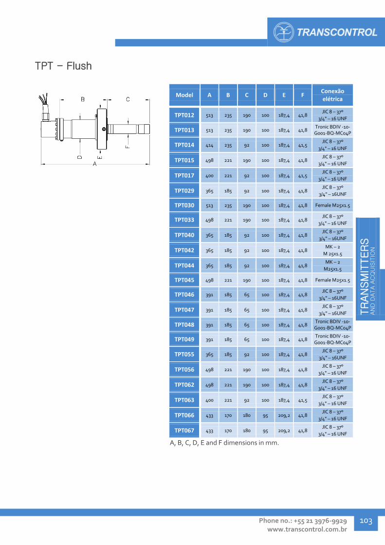
TR
AN
SM
ITTER
S
AN
D D
ATA A
CQ
UIS
ITIO
N
Phone no.: +55 21 3976-9929 www.transcontrol.com.br
103
TPT - Flush
Model A B C D E F Conexão elétrica
TPT012 513 235 190 100 187,4 41,8 JIC 8 – 37º
3/4" – 16 UNF
TPT013 513 235 190 100 187,4 41,8 Tronic BDIV -10-G001-BQ-MC04P
TPT014 414 235 92 100 187,4 41,5 JIC 8 – 37º
3/4" – 16 UNF
TPT015 498 221 190 100 187,4 41,8 JIC 8 – 37º
3/4" – 16 UNF
TPT017 400 221 92 100 187,4 41,5 JIC 8 – 37º
3/4" – 16 UNF
TPT029 365 185 92 100 187,4 41,8 JIC 8 – 37º
3/4" – 16UNF
TPT030 513 235 190 100 187,4 41,8 Female M25x1.5
TPT033 498 221 190 100 187,4 41,8 JIC 8 – 37º
3/4" – 16 UNF
TPT040 365 185 92 100 187,4 41,8 JIC 8 – 37º
3/4" – 16UNF
TPT042 365 185 92 100 187,4 41,8 MK – 2
M 25x1.5
TPT044 365 185 92 100 187,4 41,8 MK – 2
M25x1.5
TPT045 498 221 190 100 187,4 41,8 Female M25x1.5
TPT046 391 185 65 100 187,4 41,8 JIC 8 – 37º
3/4" – 16UNF
TPT047 391 185 65 100 187,4 41,8 JIC 8 – 37º
3/4" – 16UNF
TPT048 391 185 65 100 187,4 41,8 Tronic BDIV -10-G001-BQ-MC04P
TPT049 391 185 65 100 187,4 41,8 Tronic BDIV -10-G001-BQ-MC04P
TPT055 365 185 92 100 187,4 41,8 JIC 8 – 37º
3/4" – 16UNF
TPT056 498 221 190 100 187,4 41,8 JIC 8 – 37º
3/4" – 16 UNF
TPT062 498 221 190 100 187,4 41,8 JIC 8 – 37º
3/4" – 16 UNF
TPT063 400 221 92 100 187,4 41,5 JIC 8 – 37º
3/4" – 16 UNF
TPT066 433 170 180 95 209,2 41,8 JIC 8 – 37º
3/4" – 16 UNF
TPT067 433 170 180 95 209,2 41,8 JIC 8 – 37º
3/4" – 16 UNF
A, B, C, D, E and F dimensions in mm.

TR
AN
SM
ITTER
S
AN
D D
ATA A
CQ
UIS
ITIO
N
Transcontrol Catalog 2016 Edition – Rev. 01
TRANSMITTERS AND DATA ACQUISITION
104
TPT – Digital
Model A B C D E F Conexão elétrica
TPT057 533 137 206 95 200 42 Tronic BDVI-10-
G001-AA-MC04P
TPT058 533 137 206 95 200 42 Tronic BDVI-10-
G001-AA-MC04P
TPT059 533 137 206 95 200 42 Tronic BDVI-10-
G001-AA-MC04P
TPT060 533 137 206 95 200 42 JIC 8 – 37°
3/4 “ – 16 UNF
A, B, C, D, E and F dimensions in mm.
TPT – AR
Model A B C D E F Conexão elétrica
TPT007 496 216 190 87 187,4 35,8 JIC 8 – 37º
3/4" – 16 UNF
TPT028 438 158 190 100 187,4 35,8 JIC 8 – 37º
3/4" – 16 UNF
TPT032 438 158 190 100 187,4 35,8 JIC 8 – 37º
3/4" – 16 UNF
TPT035 438 158 190 100 187,4 35,8 JIC 8 – 37º
3/4" – 16 UNF
TPT036 496 216 190 87 187,4 35,8 JIC 8 – 37º
3/4" – 16 UNF
TPT041 438 158 190 100 187,4 35,8 MK – 2
M 25x1.5
TPT043 438 158 190 100 187,4 35,8 MK – 2
M 25x1.5
TPT054 438 158 190 100 187,4 35,8 Tronic BDSP-10-G003-AA-MC04P
A, B, C, D, E and F dimensions in mm.

TR
AN
SM
ITTER
S
AN
D D
ATA A
CQ
UIS
ITIO
N
Phone no.: +55 21 3976-9929 www.transcontrol.com.br
105
TPT – HR
Model A B C D E F Conexão elétrica
TPT061 435 158 190 100 187,4 20 JIC 8 – 37º
3/4" – 16 UNF
TPT078 435 158 190 100 187,4 20 JIC 8 – 37º
3/4" – 16 UNF
A, B, C, D, E and F dimensions in mm.
TPT – CANopen
Model A B C D E F Conexão elétrica
TPT068 403 136,6 192 95 187,4 41 JIC 8 – 37º
3/4" – 16 UNF
TPT070 540 136,6 190 95 187,4 41 Tronic BDIV-10-
G001-AA-HD012P
TPT071 441 136,6 91 95 187,4 41 Tronic BDIV-10-
G001-AA-HD012P
TPT072 424 136,6 190 95 187,4 41 JIC 8 – 37º
3/4" – 16 UNF
TPT073 325 136,6 91 95 187,4 41 JIC 8 – 37º
3/4" – 16 UNF "
A, B, C, D, E and F dimensions in mm.

TR
AN
SM
ITTER
S
AN
D D
ATA A
CQ
UIS
ITIO
N
Transcontrol Catalog 2016 Edition – Rev. 01
TRANSMITTERS AND DATA ACQUISITION
106
PERMANENT DOWNHOLE GAUGE - PDG
The permanent downhole gauge (PDG) is a probe equipped with state of the art pressure and temperature sensors and transmitter electronics, ensuring reliability and long life even in extremely demanding environments. Electric signal transmission between the PDG probe and surface systems is performed through a single coax wire, which is also used for supplying power to the transmitter.
Application:
Long term pressure and temperature monitoring in onshore and subsea production wells.
Technical Specification:
Pressure rating: up to 15.000 psi
Maximum pressure: up to 20.000 psi
Type of sensor: quartz crystal
Pressure accuracy: 0,02% FS.
Pressure resolution: 0,01 psi
Work temperature range: 25 – 175 °C
Temperature accuracy: ± 0,5 °C
Temperature resolution: 0,01 °C
Body material: ASTM B446-UNS-06625, UNS N07718 Inconel
Electric cable: 1/4" OD coax
Output: digital
Transcontrol offers PDG installation, test and support services, performed by our specialized team. For more information, contact us.
The communication between the transmitters and surface systems is performed through electric interfaces that perform signal decoding and retransmission, according to the specified communication protocol. More technical information about Interface Cards and Signal Acquisition Systems can be found in pages 116 to 122 of this catalog. For aid in selecting an ideal interface setup, contact Transcontrol.
Model Type Pressure
(psi) Pressure
Precision (%FS) Temp.
(°C) Temp.
Precision (°C) Connector
Voltage / current
Body material
TDG001 Single,
Standard 200 - 10000 0,02% 25 - 125 0,5 1/4" OD/DA
15 to 30 Vdc
10 mA @ 20vdc
ASTM B446-UNS-06625
TDG002 Redundant,
Standard 200 - 10000 0,02% 25 - 125 0,5 1/4" OD/DA
15 to 30 Vdc
25 mA @ 18vdc
ASTM B446-UNS-06625
TDG003 Single, HTHP
200 - 15000 0,02% 25 - 175 0,5 1/4" OD/DA 15 to 30 Vdc
10 mA @ 20vdc UNS N07718
TDG006 Single,
Standard 200 - 10000 0,02% 25 - 125 0,5 1/4" OD/DA
15 to 30 Vdc
10 mA @ 20vdc
ASTM B446-UNS-06625
TDG007 Redundant,
HTHP 200 - 15000 0,02% 25 - 175 0,5 1/4" OD/DA
15 to 30 Vdc
10 mA @ 20vdc UNS N07718
TDG008 Single,
Standard 200 - 10000 0,02% 25 - 125 0,5 1/4" OD/DA
15 to 30 Vdc
10 mA @ 20vdc
ASTM B446-UNS-06625
TDG009 Redundant,
Standard 200 - 10000 0,02% 25 - 125 0,5 1/4" OD/DA
15 to 30 Vdc
10 mA @ 20vdc
ASTM B446-UNS-06625

TR
AN
SM
ITTER
S
AN
D D
ATA A
CQ
UIS
ITIO
N
Phone no.: +55 21 3976-9929 www.transcontrol.com.br
107
When employed in production wells, PDG transmitters are installed on mandrels that, installed in the main production line, are responsible for providing the PDG with structural support and communication between the pressure and temperature sensors and the production fluid.
Transcontrol offers a range of mandrel models, specific for each application. For more information and aid in defining a model compatible with your requirements, contact Transcontrol.
Model PDG type seat Work pressure (psi) Distributed weight
(lbs/ft) Process connector Material
60DG0023 Single 5000 12,75 4.1/2"-EU-8FP SAE 4140 N80
60DG0029 Single 5000 12,75 4.1/2"-EU-8FP Super Chrome 13%
60DG0039 Single 5000 6,5 2.7/8"-EU-8FP SAE 4140 N80
60DG0043 Single 5000 9,3 3.1/2"-EU-8FP SAE 4140 N80
60DG0048 Single 5000 5,9 2.3/8"-EU-8FP SAE 4140 N80
60DG0071 Single 5000 9,3 3.1/2"-EU-8FP Super Chrome 13%
60DG0077 Single 5000 12,75 4.1/2"-EU-8FP Super Chrome 13%
60DG0082 Single 5000 5,9 2.3/8"-EU-8FP Super Chrome 13%
60DG0172 Single 5000 17 5.1/2" VAM TOP SAE 4140 N80
60DG0178 Single 5000 12,6 4.1/2" VAM TOP SAE 4140 N80
60DG0182 Single 5000 9,2 3.1/2" VAM TOP SAE 4140 N80
60DG0207 Single 5000 17 5.1/2" VAM TOP Super Chrome 13%
60DG0214 Single 5000 12,6 4.1/2" VAM TOP UNS S41425
60DG0216 Redundant 5000 12,6 4.1/2" VAM TOP UNS S41425
60DG0217 Redundant 5000 12,6 4.1/2" VAM TOP SAE 4140 N80
60DG0224 Redundant 5000 9,2 3.1/2" VAM TOP SAE 4140 N80
60DG0227 Single 5000 9,2 3.1/2" VAM TOP Super Chrome 13%
60DG0229 Redundant 5000 9,2 3.1/2" VAM TOP Super Chrome 13%
60DG0231 Redundant 5000 17 5.1/2" VAM TOP SAE 4140 N80
60DG0235 Redundant 5000 17 5.1/2" VAM TOP Super Chrome 13%
60DG0264 Single 5000 9,3 3.1/2"-EU-8FP SAE 4140 N80
60DG0266 Single 5000 4,7 2.3/8"-EU-8FP SAE 4140 N80
Didn't find what you were looking for?
Contact Transcontrol. We develop projects and solutions according to your specifications.

TR
AN
SM
ITTER
S
AN
D D
ATA A
CQ
UIS
ITIO
N
Transcontrol Catalog 2016 Edition – Rev. 01
TRANSMITTERS AND DATA ACQUISITION
108
PDG - Single
Model A B Inlet
connector
TDG001 881 22,3 1/4" OD/DA
TDG003 881 22,3 1/4" OD/DA
TDG006 651 22,3 1/4" OD/DA
TDG008 618 22,3 1/4" OD/DA
A and B dimensions in mm.
PDG - Redundant
Model A B C Inlet
connector
TDG002 894 22,3 70 1/4" OD/DA
TDG007 719 22,3 54 1/4" OD/DA
TDG009 719 22,3 54 1/4" OD/DA
A, B and C dimensions in mm.
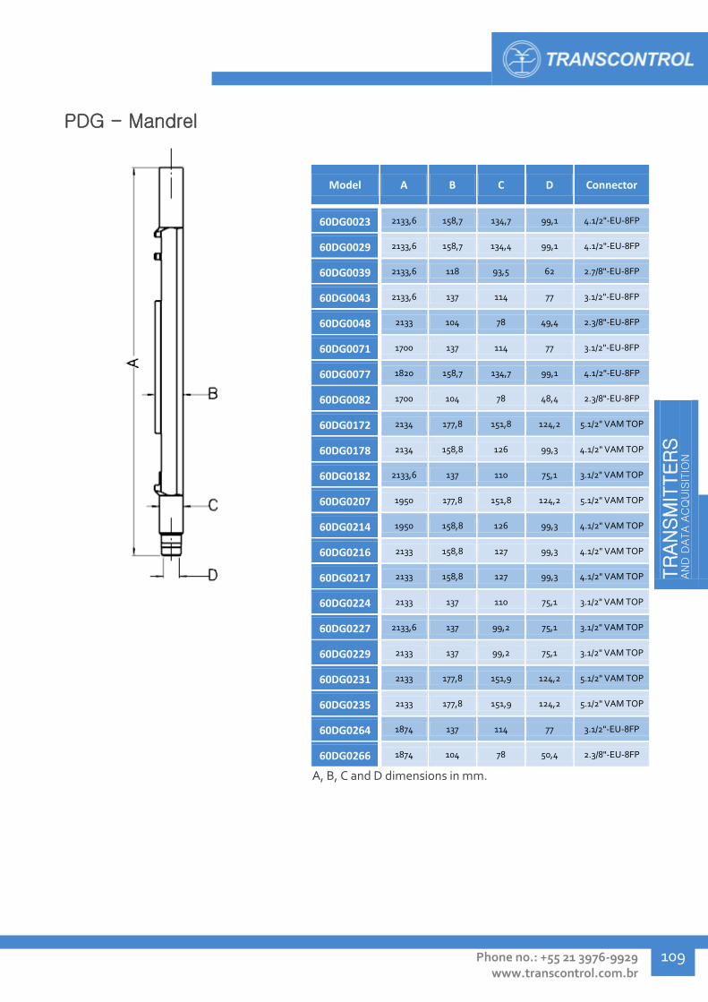
TR
AN
SM
ITTER
S
AN
D D
ATA A
CQ
UIS
ITIO
N
Phone no.: +55 21 3976-9929 www.transcontrol.com.br
109
PDG - Mandrel
Model A B C D Connector
60DG0023 2133,6 158,7 134,7 99,1 4.1/2"-EU-8FP
60DG0029 2133,6 158,7 134,4 99,1 4.1/2"-EU-8FP
60DG0039 2133,6 118 93,5 62 2.7/8"-EU-8FP
60DG0043 2133,6 137 114 77 3.1/2"-EU-8FP
60DG0048 2133 104 78 49,4 2.3/8"-EU-8FP
60DG0071 1700 137 114 77 3.1/2"-EU-8FP
60DG0077 1820 158,7 134,7 99,1 4.1/2"-EU-8FP
60DG0082 1700 104 78 48,4 2.3/8"-EU-8FP
60DG0172 2134 177,8 151,8 124,2 5.1/2" VAM TOP
60DG0178 2134 158,8 126 99,3 4.1/2" VAM TOP
60DG0182 2133,6 137 110 75,1 3.1/2" VAM TOP
60DG0207 1950 177,8 151,8 124,2 5.1/2" VAM TOP
60DG0214 1950 158,8 126 99,3 4.1/2" VAM TOP
60DG0216 2133 158,8 127 99,3 4.1/2" VAM TOP
60DG0217 2133 158,8 127 99,3 4.1/2" VAM TOP
60DG0224 2133 137 110 75,1 3.1/2" VAM TOP
60DG0227 2133,6 137 99,2 75,1 3.1/2" VAM TOP
60DG0229 2133 137 99,2 75,1 3.1/2" VAM TOP
60DG0231 2133 177,8 151,9 124,2 5.1/2" VAM TOP
60DG0235 2133 177,8 151,9 124,2 5.1/2" VAM TOP
60DG0264 1874 137 114 77 3.1/2"-EU-8FP
60DG0266 1874 104 78 50,4 2.3/8"-EU-8FP
A, B, C and D dimensions in mm.

TR
AN
SM
ITTER
S
AN
D D
ATA A
CQ
UIS
ITIO
N
Transcontrol Catalog 2016 Edition – Rev. 01
TRANSMITTERS AND DATA ACQUISITION
110
DOWNHOLE GAUGE- TTP
TTP Downhole gauges are measurement probes that integrate a set of high precision pressure and temperature sensors, designed to allow reliable, constant monitoring of the onshore production well environment.
1/4" coax electrical cable is used for communication between the transmitter and acquisition interfaces. The same conduit is used to supply the Downhole gauge with electrical power.
Application:
Pressure and temperature monitoring in onshore production wells.
Technical Specification:
Pressure rating: up to 5000 psi
Maximum pressure: up to 10000 psi
Sensor type: quartz crystal
Pressure accuracy: 0.1% F.S
Work temperature: up to 130 °C (266 °F)
Temperature accuracy: 0.5% F.S
Body material: AISI 316L, UNS S32550 Duplex
Main connector: 1/8" NPT-F
Electric cable: 1/4" OD Coax
Output: 4-20 mA
Model Type Pressure
(psi) Pressure accuracy
Temp. (°C)
Temperaure accuracy
Main connector
Cable connector
Body material
TTP001 Pressure and temperature
3000 0.10% 0° to 130° 0.50% 1/8" NPT-F 1/4" OD AISI 316L
TTP002 Pressure and temperature
5000 0.10% 0° to 130° 0.50% 1/8" NPT-F 1/4" OD S32550 Duplex
Didn't find what you were looking for?
Contact Transcontrol. We develop projects and solutions according to your specifications.

TR
AN
SM
ITTER
S
AN
D D
ATA A
CQ
UIS
ITIO
N
Phone no.: +55 21 3976-9929 www.transcontrol.com.br
111
Downhole Gauge - Standard
Model A B Main
connector Cable
connector
TTP001 447 26 1/8" NPT-F 1/4" OD
TTP002 449 26 1/8" NPT-F 1/4" OD
A and B dimensions in mm.

TR
AN
SM
ITTER
S
AN
D D
ATA A
CQ
UIS
ITIO
N
Transcontrol Catalog 2016 Edition – Rev. 01
TRANSMITTERS AND DATA ACQUISITION
112
COAXIAL ELECTRICAL CABLE SPLICE - TEE
Transcontrol electrical cable splices have been designed to allow the semi-permanent splicing between coaxial subsea communication cables, ensuring that the signal transfer is reliably maintained. Ferrule based sealing and cable locking systems prevent any interference from external fluid to the cable's electrical conduit.
Simple electrical splices are used for straight joining of two cable ends, while Y splices allow a single cable to separate in two, so that different electrical systems can share the same conduit.
Application:
Splicing of coaxial subsea electrical cables of 1/4" OD tubing and #18 AWG or #16 AWG conduits, in surface or subsea environments (dry mating).
Technical Specification:
Pressure rating: up to 10.000 psi
Work temperature range: 0 to 120 ºC
Body material: AISI 316, UNS S32750 Super duplex
Fluid: Seawater, raw oil
Electric insulation: At 20 ºC (68 °F): > 10 GΩ At 120 ºC (248 °F): > 1 GΩ
Sealing: Ferrule metal x metal, Viton soft-seal
Model Splice type Electrical
connection Work pressure
(psi) Work temperature
(°C) Cable
connector Material
TEE001 Simple Penetrator 3000 0-120 1/4" OD AISI 316
TEE002 Y Penetrator 3000 0-120 1/4" OD AISI 316
TEE003 Simple Penetrator 10000 2-120 1/4" OD UNS S32750 Superduplex
TEE004 Y Penetrator 5000 2-120 1/4" OD UNS S32750 Superduplex
TEE005 Y compact Soldered wire 3000 2-120 1/4" OD AISI 316
Didn't find what you were looking for?
Contact Transcontrol. We develop projects and solutions according to your specifications.

TR
AN
SM
ITTER
S
AN
D D
ATA A
CQ
UIS
ITIO
N
Phone no.: +55 21 3976-9929 www.transcontrol.com.br
113
Coaxial electrical cable splice - Simple
Model A B Cable
connector
TEE001 349 19 1/4" OD
TEE003 349 19 1/4" OD
A, B, C and D dimensions in mm.
Coaxial electrical cable splice - Y
Model A B C D Cable
connector
TEE002 401 50 23 19 1/4" OD
TEE004 398 60 23 19 1/4" OD
A, B, C and D dimensions in mm.
Coaxial electrical cable splice – Y compact
Model A B C D Cable
connector
TEE005 162 65 28 110 1/4" OD
A, B, C and D dimensions in mm.

TR
AN
SM
ITTER
S
AN
D D
ATA A
CQ
UIS
ITIO
N
Transcontrol Catalog 2016 Edition – Rev. 01
TRANSMITTERS AND DATA ACQUISITION
114
V-CONE FLOW METER - TMV
The line of Transcontrol V-Cone flow meters has been designed to allow a precise flow measurement in onshore and subsea ducts and fluid transport systems. V-Cone flow meters do not employ moving parts for its operation, ensuring highly precise measurements even in high flow ranges.
The V-Cone design stabilizes the fluid flow before the measurement points while dispensing flow stabilizers, providing flexibility during installation in dimensional constrained projects, while providing excellent accuracy, repeatability, signal stability, measurement ranges and longer work life. The hydrodynamic cone design also offers lower fluid pressure drop when compared to other flow measurement solutions.
Application:
Liquid or gaseous fluid flow measurement in process, production and fluid transport lines, in onshore or subsea environments.
Technical Specification:
Pressure rating: 5000 psi
Work Temperature range: -10 to 130 °C
Work depth: up to 3.000 m.
Flow range: 20 m³/h to 250 m³/h
Reynolds number range: 8.000 to 5.000.000
Accuracy: ± 0,5% to 1%
Fluid: liquid and gas
Specific mass ratio: 0,8 Kg/m³ to 1,2 Kg/m³
Interface: Flange API 17D 17SV - BX 155 ring – ring groove with Inconel 625 inlay
Main tube material: AISI 316, UNS S32750 Superduplex or Carbon steel (Inconel 625 inlay)
Transmitter vessel material: UNS S32750 Super Duplex
Power supply: 24 Vcc
Output: 4 to 20 mA analog
Model Type Pressure
(psi) Flow range
Process connection
Conexão elétrica Body
material Inlay
material
TMV001 Standard 5000 400 to 2000 m³/d 17SV-BX 155 Flange Hose, 3/4" JIC 8-37°
thread AISI 316 -
TMV002 Standard 5000 240 to 2000 m³/d 17SV-BX 155 Flange Tronic BRSP-10-B018-
BQAF-HD07P AISI 316 -
TMV003 Standard 5000 1000 to 5000 m³/d 17SV-BX 155 Flange Tronic BDIV-10-G001-
BQ-MC04P UNS S32750 Superduplex
Inconel 625
TMV004 Standard 5000 1000 to 3000 m³/d 17SV-BX 155 Flange Tronic BDIV-10-G001-
BQ-MC04P UNS S32750 Superduplex
Inconel 625
TMV005 Standard 5000 600 to 6000 m³/d 17SV-BX 155 Flange Tronic BDIV-10-G001-
BQ-MC04P UNS S32750 Superduplex
Inconel 625
TMV006 Redundant 5000 1000 to 6000 m³/d 17SV-BX 155 Flange Tronic BDIV-10-G001-
BQ-MC04P Carbon steel Inconel 625
TMV007 Standard 5000 240 to 2000 m³/d 17SV-BX 155 Flange Tronic BRSP-10-B018-
BQAF-HD07P UNS S32750 Superduplex
Inconel 625
Didn't find what you were looking for?
Contact Transcontrol. We develop projects and solutions according to your specifications.

TR
AN
SM
ITTER
S
AN
D D
ATA A
CQ
UIS
ITIO
N
Phone no.: +55 21 3976-9929 www.transcontrol.com.br
115
V-cone flow meter - Standard
Model A B C D Inlet
connector
TMV001 900 310 103 610 Flange 17SV-BX
155
TMV002 900 310 103 610 Flange 17SV-BX
155
TMV003 900 310 103 422 Flange 17SV-BX
155
TMV004 900 310 103 422 Flange 17SV-BX
155
TMV005 900 312 103 438 Flange 17SV-BX
155
TMV007 900 312 95 463 Flange 17SV-BX
155
A, B, C and D dimensions in mm.
V-Cone flow meter - Redundant
Model A B C D Inlet
connector
TMV006 1225 312 103 509 Flange 17SV-BX
155
A, B, C and D dimensions in mm.
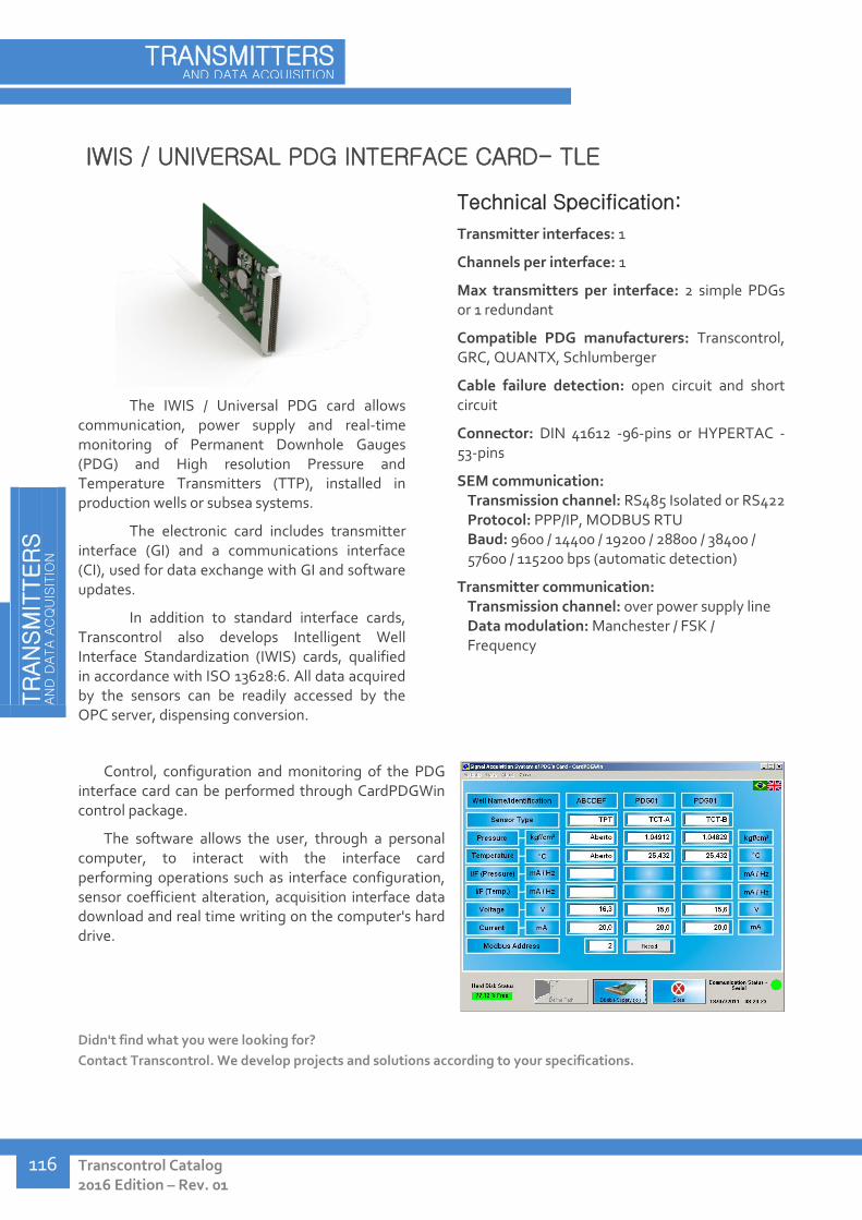
TR
AN
SM
ITTER
S
AN
D D
ATA A
CQ
UIS
ITIO
N
Transcontrol Catalog 2016 Edition – Rev. 01
TRANSMITTERS AND DATA ACQUISITION
116
IWIS / UNIVERSAL PDG INTERFACE CARD- TLE
The IWIS / Universal PDG card allows communication, power supply and real-time monitoring of Permanent Downhole Gauges (PDG) and High resolution Pressure and Temperature Transmitters (TTP), installed in production wells or subsea systems.
The electronic card includes transmitter interface (GI) and a communications interface (CI), used for data exchange with GI and software updates.
In addition to standard interface cards, Transcontrol also develops Intelligent Well Interface Standardization (IWIS) cards, qualified in accordance with ISO 13628:6. All data acquired by the sensors can be readily accessed by the OPC server, dispensing conversion.
Technical Specification:
Transmitter interfaces: 1
Channels per interface: 1
Max transmitters per interface: 2 simple PDGs or 1 redundant
Compatible PDG manufacturers: Transcontrol, GRC, QUANTX, Schlumberger
Cable failure detection: open circuit and short circuit
Connector: DIN 41612 -96-pins or HYPERTAC -53-pins
SEM communication: Transmission channel: RS485 Isolated or RS422 Protocol: PPP/IP, MODBUS RTU Baud: 9600 / 14400 / 19200 / 28800 / 38400 / 57600 / 115200 bps (automatic detection)
Transmitter communication: Transmission channel: over power supply line Data modulation: Manchester / FSK / Frequency
Control, configuration and monitoring of the PDG interface card can be performed through CardPDGWin control package.
The software allows the user, through a personal computer, to interact with the interface card performing operations such as interface configuration, sensor coefficient alteration, acquisition interface data download and real time writing on the computer's hard drive.
Didn't find what you were looking for?
Contact Transcontrol. We develop projects and solutions according to your specifications.

TR
AN
SM
ITTER
S
AN
D D
ATA A
CQ
UIS
ITIO
N
Phone no.: +55 21 3976-9929 www.transcontrol.com.br
117
SIGNAL ACQUISITION SYSTEM (SAS) - TLE
The Signal Acquisition System (SAS) designed by Transcontrol allows monitoring and testing of pressure and temperature transmitters installed in subsea systems. Supported transmitters are Permanent Downhole Gauges (PDGs), High Resolution Pressure and Temperature Transmitters (TPT-AR), Digital Pressure and Temperature Transmitters and analog output (4-20 mA) transmitters.
The SASRack allows, other than monitoring the process variables, time interval and pressure delta data logging at steps defined by the user. The SASRack also allows reading of data from other supervisory systems, via RS232, RS485 and Ethernet.
Technical Specification:
Number of interfaces: 10
Interface compatibility: automatic identification of transmitter type
Digital: PDGs (Transcontrol, Expor/QUANTX, GRC, Halliburton, Schlumberger), TPT-AR (Transcontrol), TPT-Digital (Transcontrol) Analog: two wire 4-20 mA analog pressure and temperature transmitters
Power supply: 85-265 Vac, 24 Vdc (Max 2A)
Transmitter supply: Max 36 Vdc
Supervisory communication interface: DB9 female connector (rear panel): RS232 with MODBUS RTU communication protocol – dedicated for read CPU, configuration and storage. DB9 female connector (front panel): RS232 with MODBUS RTU communication protocol. 2 way connector: RS485 with MODBUS RTU communication protocol. RJ 45 network connector: Ethernet with MODBUS RTU communication protocol.
All interfaces contain a MODBUS address that allows communication with SASRackWin software supplied with the equipment or the supervisory system that manages the plant. Communication can be established via RS232, RS485 or Ethernet.
The software provides assistance during configuration and data acquisition from each interface, such as programming date and time, sensor type configuration, sensor coefficient, stored data management, transmitter power supply configuration, consumption current monitoring, and others.
Didn't find what you were looking for?
Contact Transcontrol. We develop projects and solutions according to your specifications.
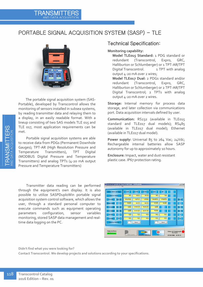
TR
AN
SM
ITTER
S
AN
D D
ATA A
CQ
UIS
ITIO
N
Transcontrol Catalog 2016 Edition – Rev. 01
TRANSMITTERS AND DATA ACQUISITION
118
PORTABLE SIGNAL ACQUISITION SYSTEM (SASP) - TLE
The portable signal acquisition system (SAS-Portable), developed by Transcontrol allows the monitoring of sensors installed in subsea systems, by reading transmitter data and relaying them to a display, in an easily readable format. With a lineup consisting of two SAS models TLE 015 and TLE 017, most application requirements can be met.
Portable signal acquisition systems are able to receive data from PDGs (Permanent Downhole Gauges); TPT-AR (High Resolution Pressure and Temperature Transmitters), TPT Digital (MODBUS Digital Pressure and Temperature Transmitters) and analog TPTs (4-20 mA output Pressure and Temperature Transmitters)
Technical Specification:
Monitoring capability: Model TLE015 Standard: 1 PDG standard or redundant (Transcontrol, Expro, GRC, Halliburton or Schlumberger) or 1 TPT-AR/TPT Digital Transcontrol. 1 TPT with analog output 4-20 mA over 2 wires; Model TLE017 Dual: 2 PDGs standard and/or redundant (Transcontrol, Expro, GRC, Halliburton or Schlumberger) or 2 TPT-AR/TPT Digital Transcontrol; 2 TPTs with analog output 4-20 mA over 2 wires.
Storage: Internal memory for process data storage, and later collection via communications port. Data acquisition intervals defined by user.
Communication: RS232 (available in TLE015 standard and TLE017 dual models); RS485 (available in TLE017 dual model); Ethernet (available in TLE017 dual model).
Power supply: Universal 85 to 264 Vac; 24Vdc; Rechargeable internal batteries allow SASP autonomy for up to approximately 10 hours.
Enclosure: Impact, water and dust resistant plastic case. IP67 protection rating.
Transmitter data reading can be performed through the equipment's own display. It is also possible to utilize SASPDuploWin portable signal acquisition system control software, which allows the user, through a standard personal computer to execute commands such as equipment operating parameters configuration, sensor variables monitoring, stored SASP data management and real-time data logging on the PC.
Didn't find what you were looking for?
Contact Transcontrol. We develop projects and solutions according to your specifications.
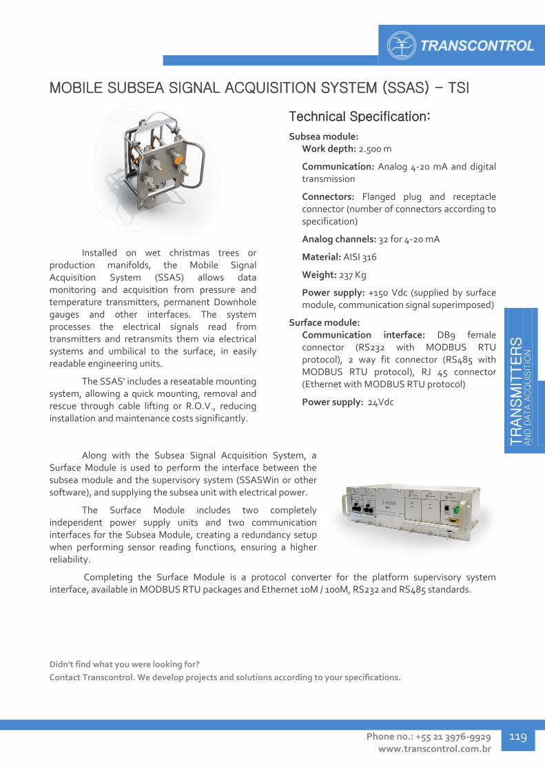
TR
AN
SM
ITTER
S
AN
D D
ATA A
CQ
UIS
ITIO
N
Phone no.: +55 21 3976-9929 www.transcontrol.com.br
119
MOBILE SUBSEA SIGNAL ACQUISITION SYSTEM (SSAS) - TSI
Installed on wet christmas trees or production manifolds, the Mobile Signal Acquisition System (SSAS) allows data monitoring and acquisition from pressure and temperature transmitters, permanent Downhole gauges and other interfaces. The system processes the electrical signals read from transmitters and retransmits them via electrical systems and umbilical to the surface, in easily readable engineering units.
The SSAS' includes a reseatable mounting system, allowing a quick mounting, removal and rescue through cable lifting or R.O.V., reducing installation and maintenance costs significantly.
Technical Specification:
Subsea module: Work depth: 2.500 m
Communication: Analog 4-20 mA and digital transmission
Connectors: Flanged plug and receptacle connector (number of connectors according to specification)
Analog channels: 32 for 4-20 mA
Material: AISI 316
Weight: 237 Kg
Power supply: +150 Vdc (supplied by surface module, communication signal superimposed)
Surface module: Communication interface: DB9 female connector (RS232 with MODBUS RTU protocol), 2 way fit connector (RS485 with MODBUS RTU protocol), RJ 45 connector (Ethernet with MODBUS RTU protocol)
Power supply: 24Vdc
Along with the Subsea Signal Acquisition System, a Surface Module is used to perform the interface between the subsea module and the supervisory system (SSASWin or other software), and supplying the subsea unit with electrical power.
The Surface Module includes two completely independent power supply units and two communication interfaces for the Subsea Module, creating a redundancy setup when performing sensor reading functions, ensuring a higher reliability.
Completing the Surface Module is a protocol converter for the platform supervisory system interface, available in MODBUS RTU packages and Ethernet 10M / 100M, RS232 and RS485 standards.
Didn't find what you were looking for?
Contact Transcontrol. We develop projects and solutions according to your specifications.

TR
AN
SM
ITTER
S
AN
D D
ATA A
CQ
UIS
ITIO
N
Transcontrol Catalog 2016 Edition – Rev. 01
TRANSMITTERS AND DATA ACQUISITION
120
INDEPENDENT SUBSEA SIGNAL ACQUISITION SYSTEM (SASMI) -
TSI
The necessity of monitoring mature production wells has promoted the development of an autonomous data acquisition and storage system. Measured information can be automatically logged by the SASMI unit, so they can be accessed on surface once the data storage module is retrieved. For its operation, SASMI units do not require electrical cable or umbilical, greatly reducing setup cost.
The concept of signal acquisition applied in SASMI units is of a stand-alone datalogger, aimed towards pressure and temperature transmitters (TPTs) and permanent downhole gauges (PDGs) sensor data storage.
Technical Specification:
Module mounting skid: Weight: 2.000 kg Material: carbon steel with anti rust painting and cathodic protection
Signal acquisition module (SASMI) Power supply: 8x 3,6 Volts / 30Ah lithium batteries Memory: 128 Mb Dry weight: 173 kg Material: AISI 316 Can be transported by R.O.V.
Portable reading unit Power supply: universal 85 to 265 Vac, 24 Vdc; rechargeable internal batteries – aprox. 10 hour autonomy Interface: serial RS232 communication through DB9 female connector Enclosure: Impact, water and dust resistant plastic case. IP67 protection rating. Dimensions: 34 x 29,5 x 15,2 cm
Data storage unit Memory: 128 Mb Weight: 2 kg
The SASMI unit is typically installed in subsea environments close to the production systems. It is composed of a support skid, a signal acquisition module, a portable reading unit and a data storage unit.
Skid Acquisition module Portable reading unit Data storage unit
Didn't find what you were looking for?
Contact Transcontrol. We develop projects and solutions according to your specifications.
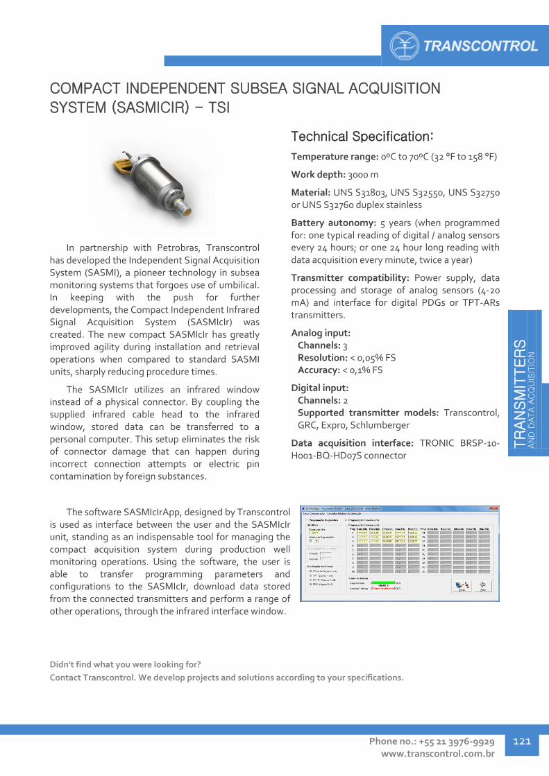
TR
AN
SM
ITTER
S
AN
D D
ATA A
CQ
UIS
ITIO
N
Phone no.: +55 21 3976-9929 www.transcontrol.com.br
121
COMPACT INDEPENDENT SUBSEA SIGNAL ACQUISITION
SYSTEM (SASMICIR) - TSI
In partnership with Petrobras, Transcontrol has developed the Independent Signal Acquisition System (SASMI), a pioneer technology in subsea monitoring systems that forgoes use of umbilical. In keeping with the push for further developments, the Compact Independent Infrared Signal Acquisition System (SASMIcIr) was created. The new compact SASMIcIr has greatly improved agility during installation and retrieval operations when compared to standard SASMI units, sharply reducing procedure times.
The SASMIcIr utilizes an infrared window instead of a physical connector. By coupling the supplied infrared cable head to the infrared window, stored data can be transferred to a personal computer. This setup eliminates the risk of connector damage that can happen during incorrect connection attempts or electric pin contamination by foreign substances.
Technical Specification:
Temperature range: 0ºC to 70ºC (32 °F to 158 °F)
Work depth: 3000 m
Material: UNS S31803, UNS S32550, UNS S32750 or UNS S32760 duplex stainless
Battery autonomy: 5 years (when programmed for: one typical reading of digital / analog sensors every 24 hours; or one 24 hour long reading with data acquisition every minute, twice a year)
Transmitter compatibility: Power supply, data processing and storage of analog sensors (4-20 mA) and interface for digital PDGs or TPT-ARs transmitters.
Analog input: Channels: 3 Resolution: < 0,05% FS Accuracy: < 0,1% FS
Digital input: Channels: 2 Supported transmitter models: Transcontrol, GRC, Expro, Schlumberger
Data acquisition interface: TRONIC BRSP-10-H001-BQ-HD07S connector
The software SASMIcIrApp, designed by Transcontrol is used as interface between the user and the SASMIcIr unit, standing as an indispensable tool for managing the compact acquisition system during production well monitoring operations. Using the software, the user is able to transfer programming parameters and configurations to the SASMIcIr, download data stored from the connected transmitters and perform a range of other operations, through the infrared interface window.
Didn't find what you were looking for?
Contact Transcontrol. We develop projects and solutions according to your specifications.

TR
AN
SM
ITTER
S
AN
D D
ATA A
CQ
UIS
ITIO
N
Transcontrol Catalog 2016 Edition – Rev. 01
TRANSMITTERS AND DATA ACQUISITION
122
SUBSEA ELECTRICAL MONITORING SYSTEM - TSE
Connected to wet christmas trees or production manifolds, the Subsea Electrical Monitoring System integrates transmitters and other monitoring interfaces, transmitting their signal in engineering units via electrical jumpers and umbilical to the surface, in order to allow monitoring and interaction with subsea wells' operation. The Electric Monitoring Systems' control can be performed by the wet Christmas tree, R.O.V and/or the platform system.
The Electrical Monitoring Systems manufactured by Transcontrol use in-house equipment such as TPT and PDG transmitters, ensuring perfect compatibility and integration through the system. The Electrical System is, however, designed with flexibility to allow interaction with third-party transmitters.
Application:
Subsea electrical monitoring and control systems, for wet christmas trees and production manifolds.
Technical Specification:
Work depth: Components qualified for work in depth up to 2.500 meters.
Water column pressure compensation in jumper hoses performed through filling with liquid silicone and pressurized at 10 bar.
Communication: Transmission of analog 4-20 mA and/or digital signals.
Main integrated components: Pressure and temperature transmitter (TPT) Compensated chamber (dual or triple output) PDG output interface Subsea signal acquisition system (SSAS) Electric / hydraulic actuators Electrical interfaces (according to specification).
Transcontrol designs each Electrical System according to the client's requirements and specifications. Our ample experience in monitoring and control systems, allied to local, specialized support in after-sales services provides a complete and highly capable solution in integrated electrical systems.
Transcontrol offers highly capable electrical system support and installation services. For more information, contact Transcontrol.
Didn't find what you were looking for?
Contact Transcontrol. We develop projects and solutions according to your specifications.

TR
AN
SM
ITTER
S
AN
D D
ATA A
CQ
UIS
ITIO
N
Tel.: +55 21 3976-9929 www.transcontrol.com.br
123
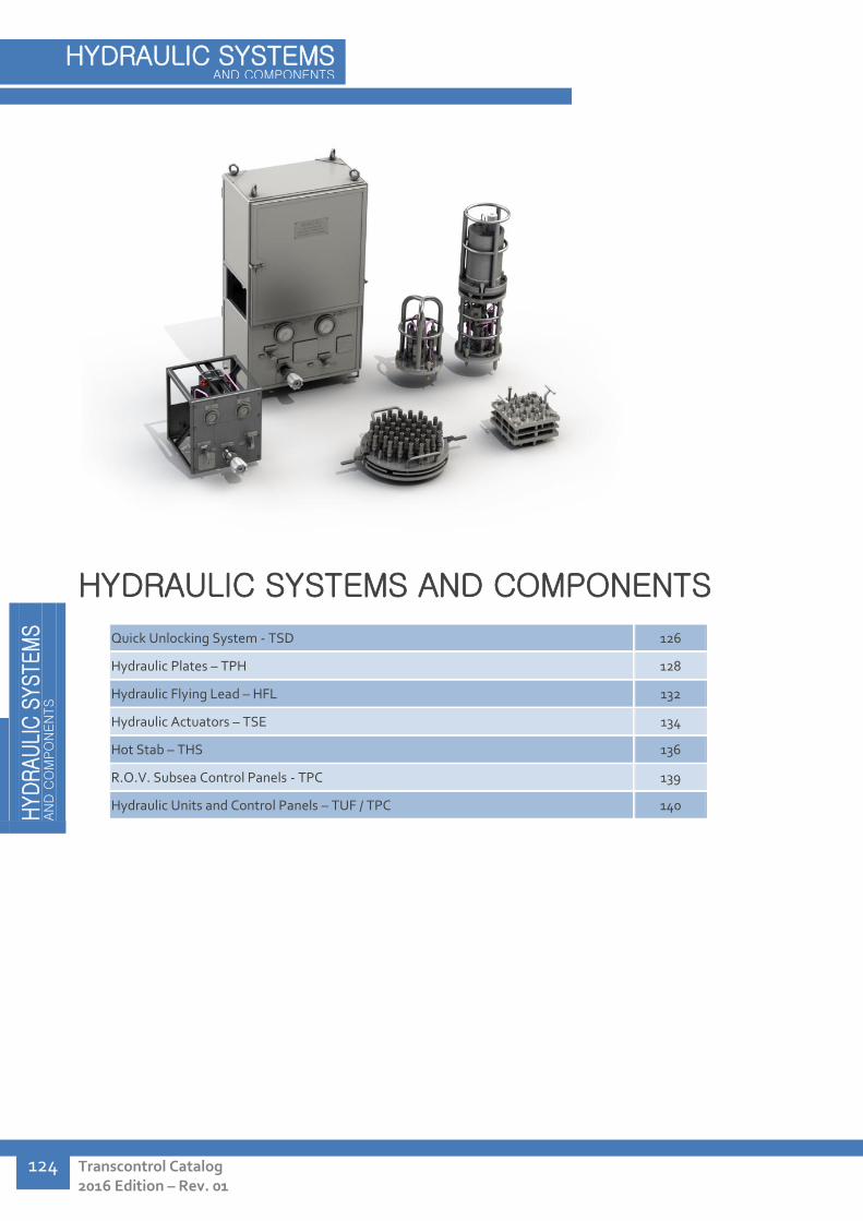
H
YD
RAU
LIC
SYSTE
MS
AN
D C
OM
PO
NEN
TS
Transcontrol Catalog 2016 Edition – Rev. 01
HYDRAULIC SYSTEMS AND COMPONENTS
124
HYDRAULIC SYSTEMS AND COMPONENTS
Quick Unlocking System - TSD 126
Hydraulic Plates – TPH 128
Hydraulic Flying Lead – HFL 132
Hydraulic Actuators – TSE 134
Hot Stab – THS 136
R.O.V. Subsea Control Panels - TPC 139
Hydraulic Units and Control Panels – TUF / TPC 140
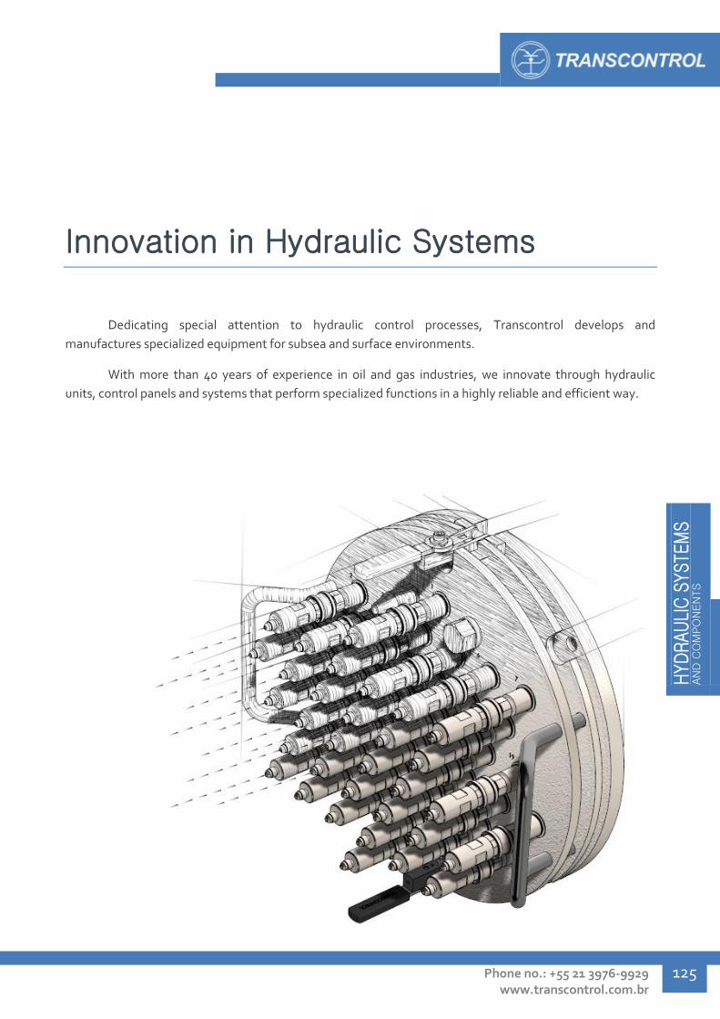
HYD
RAU
LIC
SYSTE
MS
AN
D C
OM
PO
NEN
TS
Phone no.: +55 21 3976-9929 www.transcontrol.com.br
125
Innovation in Hydraulic Systems
Dedicating special attention to hydraulic control processes, Transcontrol develops and
manufactures specialized equipment for subsea and surface environments.
With more than 40 years of experience in oil and gas industries, we innovate through hydraulic
units, control panels and systems that perform specialized functions in a highly reliable and efficient way.
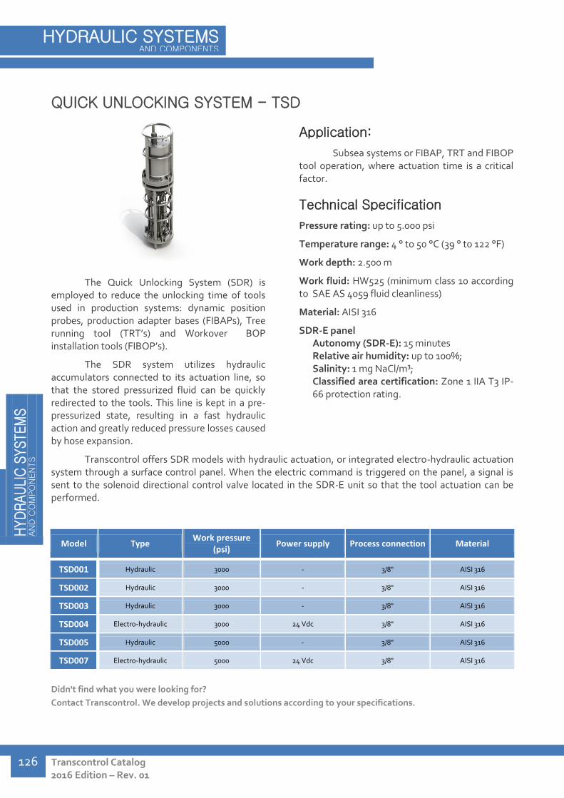
H
YD
RAU
LIC
SYSTE
MS
AN
D C
OM
PO
NEN
TS
Transcontrol Catalog 2016 Edition – Rev. 01
HYDRAULIC SYSTEMS AND COMPONENTS
126
QUICK UNLOCKING SYSTEM - TSD
The Quick Unlocking System (SDR) is employed to reduce the unlocking time of tools used in production systems: dynamic position probes, production adapter bases (FIBAPs), Tree running tool (TRT’s) and Workover BOP installation tools (FIBOP’s).
The SDR system utilizes hydraulic accumulators connected to its actuation line, so that the stored pressurized fluid can be quickly redirected to the tools. This line is kept in a pre-pressurized state, resulting in a fast hydraulic action and greatly reduced pressure losses caused by hose expansion.
Application:
Subsea systems or FIBAP, TRT and FIBOP tool operation, where actuation time is a critical factor.
Technical Specification
Pressure rating: up to 5.000 psi
Temperature range: 4 ° to 50 °C (39 ° to 122 °F)
Work depth: 2.500 m
Work fluid: HW525 (minimum class 10 according to SAE AS 4059 fluid cleanliness)
Material: AISI 316
SDR-E panel Autonomy (SDR-E): 15 minutes Relative air humidity: up to 100%; Salinity: 1 mg NaCl/m³; Classified area certification: Zone 1 IIA T3 IP-66 protection rating.
Transcontrol offers SDR models with hydraulic actuation, or integrated electro-hydraulic actuation system through a surface control panel. When the electric command is triggered on the panel, a signal is sent to the solenoid directional control valve located in the SDR-E unit so that the tool actuation can be performed.
Model Type Work pressure
(psi) Power supply Process connection Material
TSD001 Hydraulic 3000 - 3/8" AISI 316
TSD002 Hydraulic 3000 - 3/8" AISI 316
TSD003 Hydraulic 3000 - 3/8" AISI 316
TSD004 Electro-hydraulic 3000 24 Vdc 3/8" AISI 316
TSD005 Hydraulic 5000 - 3/8" AISI 316
TSD007 Electro-hydraulic 5000 24 Vdc 3/8" AISI 316
Didn't find what you were looking for?
Contact Transcontrol. We develop projects and solutions according to your specifications.

HYD
RAU
LIC
SYSTE
MS
AN
D C
OM
PO
NEN
TS
Phone no.: +55 21 3976-9929 www.transcontrol.com.br
127
SDR – Subsea hydraulic actuation module
The main function of the subsea hydraulic actuation module is to redirect the hydraulic supply from the accumulator bank to the unlock function of the wet christmas tree tools, as soon as the unlocking command line pressure is raised via surface control panel.
The main components of the subsea module are block, shuttle, quick release and relief valves, besides monitoring systems. The subsea module includes a cover cage, consisting of AISI 316 tubes, to provide protection from impacts.
SDR-E – Subsea electric actuation module
Attached to a subsea hydraulic actuation unit, the electric module is an evolution of the standard hydraulic SDR. By adopting an electric actuating system the SDR-E optimizes the hydraulic module operation time, as it negates any delay caused by umbilical hose expansion.
The main components of the subsea electric actuation module are solenoid directional control valve, pressure transmitter, block, shuttle, quick release and relief valves, and monitoring sensors. The subsea module includes a cover cage, consisting of AISI 316 tubes, to provide protection from impacts.
The hydraulic panel includes electric junction box containing a No-break system, conferring autonomy to the SDR-E in case of power outage. This system is able to supply the hydraulic panel, control panel and subsea module with electricity for at least 15 minutes.
The panel's structure is composed of AISI 316L tube and sheets, including doors to allow access to the panel interior and operator safety during pressurization. It has been designed to ensure rigidity under adverse conditions and includes lifting lugs, able to withstand twice the panel's weight.
The main components utilized in the panel are solenoid directional control, shuttle, block, pressure regulation valves, besides pressure gauges and transmitters.
The command panel, installed classified area (explosion-proof) is employed to combine the system interfaces and commands, so the operator can promptly monitor the system conditions, perform the actuation functions and receive confirmation of proper SDR operation from a single control panel.

H
YD
RAU
LIC
SYSTE
MS
AN
D C
OM
PO
NEN
TS
Transcontrol Catalog 2016 Edition – Rev. 01
HYDRAULIC SYSTEMS AND COMPONENTS
128
HYDRAULIC PLATES – TPH
The main function of the Hydraulic Plate is to provide an interface between the umbilical and the wet christmas tree. By employing double-seal quick connection couplers, mating and de-mating operations can be performed while avoiding process fluid contamination.
Hydraulic Plates are compromised of two main components: the flying upper plate containing the quick couplings where the umbilical are connected; and the lower plate, fixed to the wet christmas tree.
Application:
As interface between wet christmas trees or subsea systems, and umbilical supplying hydraulic power.
Technical Specification:
Pressure rating: up to 15.000 psi
Connectors: 1/4" Jic-04-M, 1/4" JIC-37°-M, 3/8" OD, 3/8" NPT
Number of couplings: 4, 9, 10, 12, 18, 24, 25, 32, 40, 45, 48
Fluid: HW525
Work fluid cleanliness: minimum NAS 1683 class 8.
Couplings sealing: Soft-seal
Material: AISI 316
Model Work pressure
(psi) Number of couplings
Connector A Connector B Material
TPH002 5000 24 1/4" JIC 04-M JIC 04-M AISI 316
TPH005 5000 24 - Blind plug AISI 316
TPH008 5000 18 1/4" JIC 04-M 3/8" OD AISI 316
TPH009 5000 18 1/4" NPT-M 3/8" OD AISI 316
TPH010 5000 40 1/4" JIC 04-M 3/8" OD AISI 316
TPH011 5000 12 1/4" JIC 04-M 1/4" OD AISI 316
TPH012 5000 9 1/4" JIC 04-M 3/8" OD AISI 316
TPH013 5000 10 1/4" JIC 04-M 3/8" OD AISI 316
TPH014 5000 4 1/4" JIC 04-M 3/8" OD AISI 316
TPH016 5000 48 1/4" JIC-37°-M 3/8" NPT-M AISI 316
TPH017 5000 24 1/4" JIC-37°-M 3/8" NPT-M AISI 316
TPH018 5000 25 1/4" JIC-37°-M 3/8" NPT-M AISI 316
TPH019 5000 12 1/4" JIC-37°-M 3/8" NPT-F AISI 316
TPH020 10000 32 1/4" JIC-37°-M 3/8" NPT-F AISI 316
TPH021 5000 24 1/4" JIC 04-M JIC 04-M AISI 316
TPH022 10000 48 1/4" JIC-37°-M 3/8" NPT-F AISI 316

HYD
RAU
LIC
SYSTE
MS
AN
D C
OM
PO
NEN
TS
Phone no.: +55 21 3976-9929 www.transcontrol.com.br
129
Model Work pressure
(psi) Number of couplings
Connector A Connector B Material
TPH023 10000 45 1/4" JIC-37°-M 3/8" NPT-F AISI 316
TPH026 15000 48 1/4" MP tubing with 7/16"
20 UNF-2B thread 1/4" MP tubing with 7/16"
20 UNF-2B thread AISI 316
TPH027 15000 45 1/4" MP tubing with 7/16" 20
UNF-2B thread 1/4" MP tubing with 7/16" 20
UNF-2B thread AISI 316
TPH028 5000 24 1/4" JIC 04-M 1/4" NPT-F AISI 316
Didn't find what you were looking for?
Contact Transcontrol. We develop projects and solutions according to your specifications.

H
YD
RAU
LIC
SYSTE
MS
AN
D C
OM
PO
NEN
TS
Transcontrol Catalog 2016 Edition – Rev. 01
HYDRAULIC SYSTEMS AND COMPONENTS
130
Hydraulic Plate – Square profile
Model A B C Connector A Connector B
TPH002 280 280 266 JIC 04-M JIC 04-M
TPH005 280 280 266 Blind stub -
TPH008 280 280 266 1/4" JIC -4-M 3/8" OD
TPH009 280 280 266 1/4" NPT-M 3/8" OD
TPH011 280 280 266 1/4" JIC -4-M 1/4" OD
TPH021 280 280 266 JIC 04-M JIC 04-M
TPH028 280 280 270 1/4" JIC -4-M 1/4" NPT-F
A, B and C dimensions in mm.

HYD
RAU
LIC
SYSTE
MS
AN
D C
OM
PO
NEN
TS
Phone no.: +55 21 3976-9929 www.transcontrol.com.br
131
Hydraulic Plate – Round profile
Model A B C Connector A Connector B
TPH010 381 128 285 1/4" JIC -4-M 3/8" OD
TPH012 300 94 250 1/4" JIC -4-M 3/8" OD
TPH013 300 94 250 1/4" JIC -4-M 3/8" OD
TPH014 180 120 225 1/4" JIC -4-M 3/8" OD
TPH016 755 75 207 1/4" JIC-37°-M 3/8" NPT-M
TPH017 641 75 207 1/4" JIC-37°-M 3/8" NPT-M
TPH018 685 75 207 1/4" JIC-37°-M 3/8" NPT-M
TPH019 641 75 207 1/4" JIC-37°-M 3/8" NPT-F
TPH020 713 75 207 1/4" JIC-37°-M 3/8" NPT-F
TPH022 755 75 207 1/4" JIC-37°-M 3/8" NPT-F
TPH023 755 75 207 1/4" JIC-37°-M 3/8" NPT-F
TPH026 755 75 193 1/4" tube MP 7/16" thread
1/4" tube MP 7/16" thread
TPH027 755 75 193 1/4" tube MP 7/16" thread
1/4" tube MP 7/16" thread
A, B and C dimensions in mm.
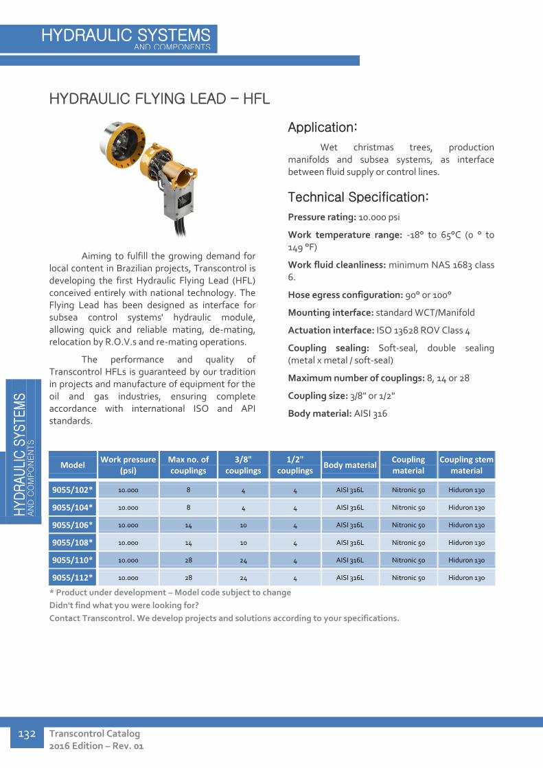
H
YD
RAU
LIC
SYSTE
MS
AN
D C
OM
PO
NEN
TS
Transcontrol Catalog 2016 Edition – Rev. 01
HYDRAULIC SYSTEMS AND COMPONENTS
132
HYDRAULIC FLYING LEAD – HFL
Aiming to fulfill the growing demand for local content in Brazilian projects, Transcontrol is developing the first Hydraulic Flying Lead (HFL) conceived entirely with national technology. The Flying Lead has been designed as interface for subsea control systems' hydraulic module, allowing quick and reliable mating, de-mating, relocation by R.O.V.s and re-mating operations.
The performance and quality of Transcontrol HFLs is guaranteed by our tradition in projects and manufacture of equipment for the oil and gas industries, ensuring complete accordance with international ISO and API standards.
Application:
Wet christmas trees, production manifolds and subsea systems, as interface between fluid supply or control lines.
Technical Specification:
Pressure rating: 10.000 psi
Work temperature range: -18° to 65°C (0 ° to 149 °F)
Work fluid cleanliness: minimum NAS 1683 class 6.
Hose egress configuration: 90° or 100°
Mounting interface: standard WCT/Manifold
Actuation interface: ISO 13628 ROV Class 4
Coupling sealing: Soft-seal, double sealing (metal x metal / soft-seal)
Maximum number of couplings: 8, 14 or 28
Coupling size: 3/8" or 1/2"
Body material: AISI 316
Model Work pressure
(psi) Max no. of couplings
3/8" couplings
1/2" couplings
Body material Coupling material
Coupling stem material
9055/102* 10.000 8 4 4 AISI 316L Nitronic 50 Hiduron 130
9055/104* 10.000 8 4 4 AISI 316L Nitronic 50 Hiduron 130
9055/106* 10.000 14 10 4 AISI 316L Nitronic 50 Hiduron 130
9055/108* 10.000 14 10 4 AISI 316L Nitronic 50 Hiduron 130
9055/110* 10.000 28 24 4 AISI 316L Nitronic 50 Hiduron 130
9055/112* 10.000 28 24 4 AISI 316L Nitronic 50 Hiduron 130
* Product under development – Model code subject to change
Didn't find what you were looking for?
Contact Transcontrol. We develop projects and solutions according to your specifications.
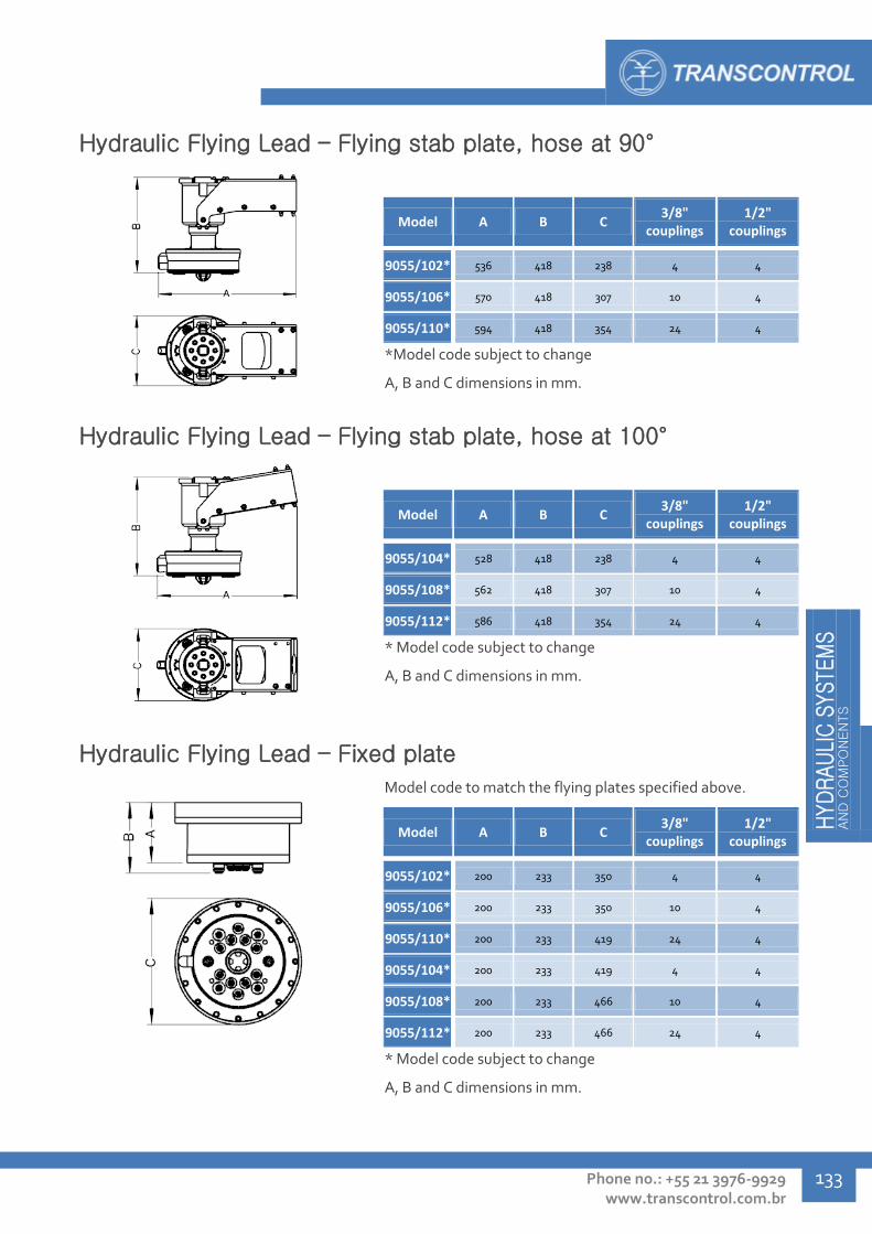
HYD
RAU
LIC
SYSTE
MS
AN
D C
OM
PO
NEN
TS
Phone no.: +55 21 3976-9929 www.transcontrol.com.br
133
Hydraulic Flying Lead – Flying stab plate, hose at 90°
Model A B C 3/8"
couplings 1/2"
couplings
9055/102* 536 418 238 4 4
9055/106* 570 418 307 10 4
9055/110* 594 418 354 24 4
*Model code subject to change
A, B and C dimensions in mm.
Hydraulic Flying Lead – Flying stab plate, hose at 100°
Model A B C 3/8"
couplings 1/2"
couplings
9055/104* 528 418 238 4 4
9055/108* 562 418 307 10 4
9055/112* 586 418 354 24 4
* Model code subject to change
A, B and C dimensions in mm.
Hydraulic Flying Lead – Fixed plate
Model code to match the flying plates specified above.
Model A B C 3/8"
couplings 1/2"
couplings
9055/102* 200 233 350 4 4
9055/106* 200 233 350 10 4
9055/110* 200 233 419 24 4
9055/104* 200 233 419 4 4
9055/108* 200 233 466 10 4
9055/112* 200 233 466 24 4
* Model code subject to change
A, B and C dimensions in mm.
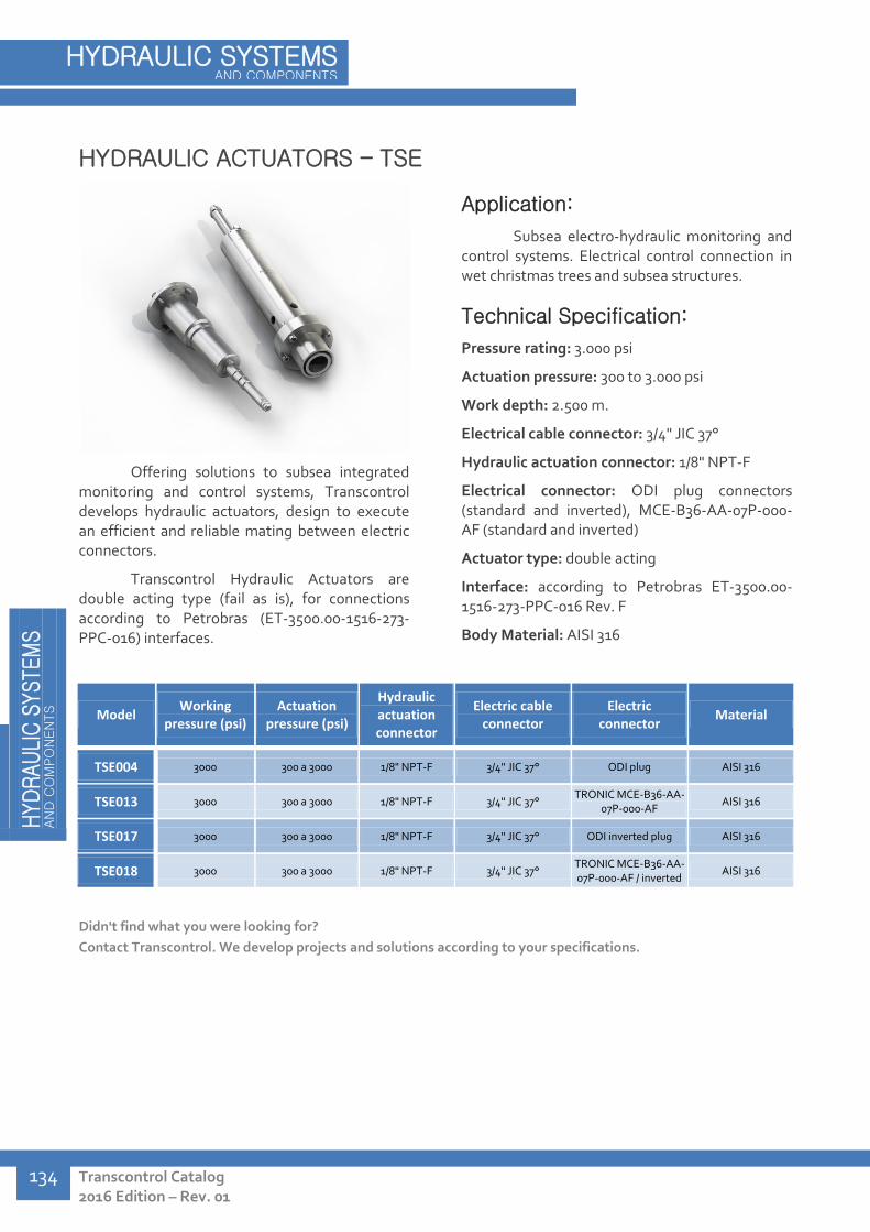
H
YD
RAU
LIC
SYSTE
MS
AN
D C
OM
PO
NEN
TS
Transcontrol Catalog 2016 Edition – Rev. 01
HYDRAULIC SYSTEMS AND COMPONENTS
134
HYDRAULIC ACTUATORS – TSE
Offering solutions to subsea integrated monitoring and control systems, Transcontrol develops hydraulic actuators, design to execute an efficient and reliable mating between electric connectors.
Transcontrol Hydraulic Actuators are double acting type (fail as is), for connections according to Petrobras (ET-3500.00-1516-273-PPC-016) interfaces.
Application:
Subsea electro-hydraulic monitoring and control systems. Electrical control connection in wet christmas trees and subsea structures.
Technical Specification:
Pressure rating: 3.000 psi
Actuation pressure: 300 to 3.000 psi
Work depth: 2.500 m.
Electrical cable connector: 3/4" JIC 37°
Hydraulic actuation connector: 1/8" NPT-F
Electrical connector: ODI plug connectors (standard and inverted), MCE-B36-AA-07P-000-AF (standard and inverted)
Actuator type: double acting
Interface: according to Petrobras ET-3500.00-1516-273-PPC-016 Rev. F
Body Material: AISI 316
Model Working
pressure (psi) Actuation
pressure (psi)
Hydraulic actuation connector
Electric cable connector
Electric connector
Material
TSE004 3000 300 a 3000 1/8" NPT-F 3/4" JIC 37° ODI plug AISI 316
TSE013 3000 300 a 3000 1/8" NPT-F 3/4" JIC 37° TRONIC MCE-B36-AA-
07P-000-AF AISI 316
TSE017 3000 300 a 3000 1/8" NPT-F 3/4" JIC 37° ODI inverted plug AISI 316
TSE018 3000 300 a 3000 1/8" NPT-F 3/4" JIC 37° TRONIC MCE-B36-AA-07P-000-AF / inverted
AISI 316
Didn't find what you were looking for?
Contact Transcontrol. We develop projects and solutions according to your specifications.

HYD
RAU
LIC
SYSTE
MS
AN
D C
OM
PO
NEN
TS
Phone no.: +55 21 3976-9929 www.transcontrol.com.br
135
Hydraulic actuator - Standard
Model A B C Conexão
cabo elétrico Conexão atuação
TSE004 569 113 69 3/4" JIC 37° 1/8" NPT-F
TSE013 569 113 69 3/4" JIC 37° 1/8" NPT-F
TSE017 569 113 69 3/4" JIC 37° 1/8" NPT-F
TSE018 569 113 69 3/4" JIC 37° 1/8" NPT-F
A, B and C dimensions in mm.

H
YD
RAU
LIC
SYSTE
MS
AN
D C
OM
PO
NEN
TS
Transcontrol Catalog 2016 Edition – Rev. 01
HYDRAULIC SYSTEMS AND COMPONENTS
136
HOT STAB – THS
The Hot Stab is a type of re-mateable hydraulic connector that can be handled by R.O.Vs and is frequently used to interconnect hydraulic functions. A series of instruments, such as pressure gauges can be connected to Hot Stabs. A blind Hot Stab model can be used to protect sockets when not in use.
The sealing system allows wet mating of Hot Stabs in ISO 13628-8 interfaces, enabling a sealed connection of instrumentation or hoses to the system.
Application:
R.O.V panels in wet christmas trees and subsea tools.
Technical Specification:
Pressure rating: up to 5.000 psi
Work depth: 2.500 m
Connectors: 9/16" and 3/4" JIC-37-M, 1/4" NPT-F, 1/4" API-LP-F
Body material: AISI 316, UNS S32760 superduplex
Sealing: Soft Seal, in nitrilic rubber
Stab tip: PTFE guide
R.O.V interface: Complacent 'T' handle
Model Work pressure
(psi) Type Connector A Connector B Material
THS001 3000 Simple 9/16" 18-JIC-37 or
3/4" 16-JIC-37 9/16" 18-JIC-37 or
3/4" 16-JIC-37 AISI 316
THS002 3000 Blind - - AISI 316
THS003 3000 Plugged 1/4" NPT-F 1/4" NPT-F AISI 316
THS004 3000 Simple 1/4" API LP 1/4" API LP AISI 316
THS005 3000 With 3.5" pressure
gauge 1/4" NPT-F - AISI 316
THS006 3000 With 2.5" pressure
gauge 1/4" NPT-F - AISI 316
THS007 7500 Simple 1/4" API LP 1/4" API LP UNS S32760
THS008 5000 Simple 9/16" 18-JIC-37 or
3/4" 16-JIC-37 9/16" 18-JIC-37 or
3/4" 16-JIC-37 AISI 316
THS009 10000 Simple 1/4" API LP 1/4" API LP UNS S32760
THS010 7500 Blind - - AISI 316
THS011 7500 Simple 9/16" 18-JIC-37 or
3/4" 16-JIC-37 9/16" 18-JIC-37 or
3/4" 16-JIC-37 UNS S32760

HYD
RAU
LIC
SYSTE
MS
AN
D C
OM
PO
NEN
TS
Phone no.: +55 21 3976-9929 www.transcontrol.com.br
137
To ensure proper function of Hot Stab components, the use of
specific receptacles, responsible for correct alignment and hydraulic line
matching are necessary. Transcontrol manufactures and supplies Hot
Stab receptacles, and develops new solutions according to each
specification.
Model Type Connections Connector A Connector B Material
25HS0016 Dual Hot Stab 2 1/4" NPT-F 1/4" NPT-F UNS S31803 duplex
25HS0019 Blind / parking 0 - - AISI 316
Didn't find what you were looking for?
Contact Transcontrol. We develop projects and solutions according to your specifications.
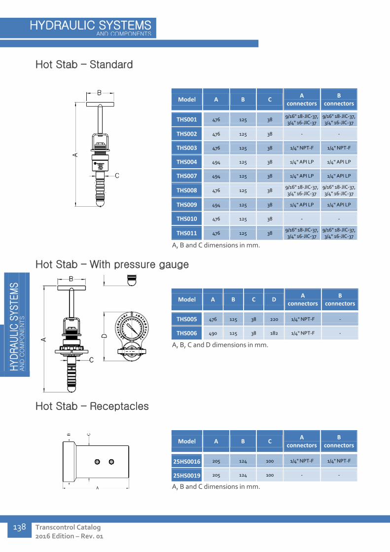
H
YD
RAU
LIC
SYSTE
MS
AN
D C
OM
PO
NEN
TS
Transcontrol Catalog 2016 Edition – Rev. 01
HYDRAULIC SYSTEMS AND COMPONENTS
138
Hot Stab – Standard
Model A B C A
connectors B
connectors
THS001 476 125 38 9/16" 18-JIC-37, 3/4" 16-JIC-37
9/16" 18-JIC-37, 3/4" 16-JIC-37
THS002 476 125 38 - -
THS003 476 125 38 1/4" NPT-F 1/4" NPT-F
THS004 494 125 38 1/4" API LP 1/4" API LP
THS007 494 125 38 1/4" API LP 1/4" API LP
THS008 476 125 38 9/16" 18-JIC-37, 3/4" 16-JIC-37
9/16" 18-JIC-37, 3/4" 16-JIC-37
THS009 494 125 38 1/4" API LP 1/4" API LP
THS010 476 125 38 - -
THS011 476 125 38 9/16" 18-JIC-37, 3/4" 16-JIC-37
9/16" 18-JIC-37, 3/4" 16-JIC-37
A, B and C dimensions in mm.
Hot Stab – With pressure gauge
Model A B C D A
connectors B
connectors
THS005 476 125 38 220 1/4" NPT-F -
THS006 490 125 38 182 1/4" NPT-F -
A, B, C and D dimensions in mm.
Hot Stab – Receptacles
Model A B C A
connectors B
connectors
25HS0016 205 124 100 1/4" NPT-F 1/4" NPT-F
25HS0019 205 124 100 - -
A, B and C dimensions in mm.

HYD
RAU
LIC
SYSTE
MS
AN
D C
OM
PO
NEN
TS
Phone no.: +55 21 3976-9929 www.transcontrol.com.br
139
R.O.V. SUBSEA CONTROL PANELS - TPC
In order to consolidate multiple hydraulic controls into one position and facilitate their actuation or the connection of acquisition systems in subsea environments, R.O.V. operated control panels are frequently used.
Transcontrol manufactures subsea control panels according to each project's specification, following Petrobras standards and requirements. Along the panels, valves, connectors and interfaces can be supplied by Transcontrol.
Application:
Control and connection interface of equipment installed in subsea environments.
Technical Specification:
Structure: Built in AISI 316 stainless steel, conferring rigid support to the panel components. According to the specifications of each project, R.O.V stabilization bars are included. The panels are designed to allow easy identification and access to each function, and include a diagram of the hydraulic system to facilitate maintenance and inspection.
The structure is apt for installation in subsea environments, as its material and/or painting systems have been qualified for such conditions.
Temperature range: 0ºC to 65ºC (32 °F to 149 °F)
Transcontrol designs and manufactures in its own facilities the interfaces used for valve actuation and other equipment operation, covering the entire productive chain in site. The end result is a more agile manufacturing process, lower end cost and maximum after sales support.
Didn't find what you were looking for?
Contact Transcontrol. We develop projects and solutions according to your specifications.

H
YD
RAU
LIC
SYSTE
MS
AN
D C
OM
PO
NEN
TS
Transcontrol Catalog 2016 Edition – Rev. 01
HYDRAULIC SYSTEMS AND COMPONENTS
140
HYDRAULIC UNITS AND CONTROL PANELS – TUF / TPC
The main function of Hydraulic Power Units is to generate hydraulic energy to supply hydraulic systems, subsea equipment installation, intervention or operation. As the main hydraulic energy source, electric powered piston/triplex and centrifugal pumps and/or hydropneumatic pumps are frequently used.
Transcontrol Hydraulic Power Units and Control Panels are designed to allow complete operability and control of hydraulic equipment and processes such as wet christmas trees, head actuators, SDRs, Riser systems, DHSVs and control systems. The main components of a Hydraulic Power Unit are hydraulic pumps, reservoir tank, control valves and fluid inlet-outlet connectors.
The Hydraulic Power Units and Control Panels designed by Transcontrol are tailored to each application, according to client's specifications. Our ample experience in hydraulic units and panels allied to after sales specialized support promotes a complete and highly qualified solution in hydraulic systems.
Application:
Supply and control of hydraulic energy in onshore or offshore systems.
Technical Specification:
Pressure output: up to 15.000 psi, according to specification
Fluids used: HW525, HW856, HD856, HW525P, HW443 or according to specification
Power supply: 220Vac / 440Vac
Structure: Constructed in AISI 316 tubes and sheets, housing all components in its interior. Large doors confer safety for the operators, while allowing quick access to the unit's instrumentation. According to the requirements of each project, umbilical and hose storage drawers are included. Explosion-proof versions are also able to be supplied, if required.
All Hydraulic Power Units and Control Panels are designed to be installed in external environments, and are built using corrosion proof materials.
Temperature range: 0ºC to 65ºC (32 °F to 149 °F)
Relative air humidity: up to 100%;
Air salinity: 1 mg NaCl/m3
Hydraulic power units can be manufactured for work under classified zones with a certain protection rating, according to client's specification.

HYD
RAU
LIC
SYSTE
MS
AN
D C
OM
PO
NEN
TS
Phone no.: +55 21 3976-9929 www.transcontrol.com.br
141
DSV Actuation Panel
The basic function of the TPC-035 Panel is to provide hydraulic energy to DHSV safety valves, ensuring that the production well is sealed in case of failure, automatically when detected by surface monitoring system or by remote or manual operation. To perform its function of pressurized fluid redirection, the Panel includes a directional control solenoid valve and a set of manually operated control valves.
Workover Panel
Workover Panels are installed for wet christmas trees operation in platform and/or production ships. To allow function pressurization, the panel includes internal pressure generation system composed of a hydropneumatic pump, control valves and filters. External power supply can also be used to pressurize the low and high pressure lines.
Hydraulic output functions are controlled by valves mounted on the front panel, including pressure gauges and indicators. To allow operational flexibility, the panel functions are able to be rearranged while replacing the function name tags.
Head Terminal Panel
Transcontrol Head Terminal panels allow complete operationability through the hydraulic control of the Head Terminal's hydraulic actuators and the column's suspensor installation tool, used during installation and intervention operations in wet christmas trees. For function pressurization, the panel includes internal pressurization system composed of hydropneumatic pump, control valves and a set of filters. External power supply can also be used to pressurize the low and high pressure lines.
Hydropneumatic Pump and Gas Booster Compact Units
Mobile power units are frequently required for temporary pressurization functions in hydraulic and pneumatic systems. Transcontrol manufactures compact, portable and modular units including hydropneumatic pumps or gas boosters, with a wide range of pressure and flow output options, capable of attending to a large number of applications in the field.
These are only a few examples of Hydraulic Power Units and Control Panels developed and manufactured at
Transcontrol.
We offer power unit and panel models tailor-made for your project. For more information, contact Transcontrol.

SERVIC
ES
Transcontrol Catalog 2016 Edition – Rev. 01
SERVICES
142
SERVICES
Hydraulic Power Unit and Control Panel Maintenance 144
Flushing Services 144
Equipment Testing and Qualification 145
Instrumentation Calibration 145
Special Machining Services 146
Hyperbaric Chamber Testing 146
Hydraulic Signature and Gate Valve Override (up to 1") Testing 147
Cladding Services 147
Field Installation Services 147
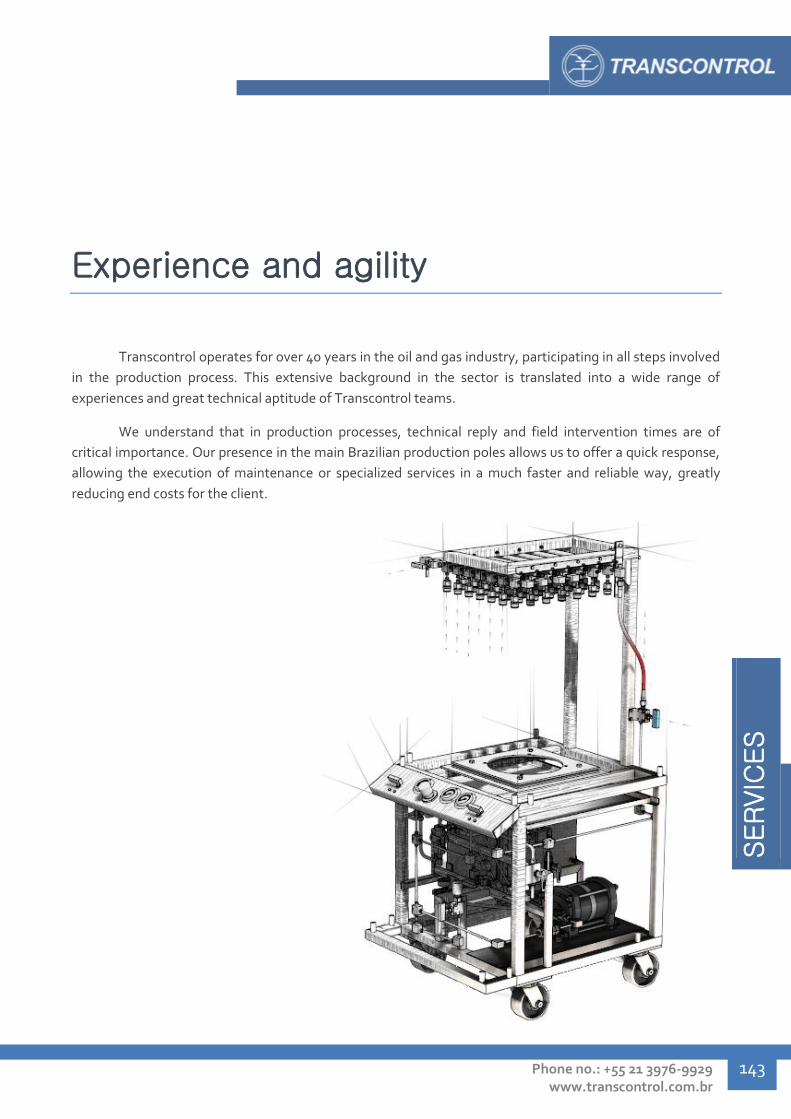
SERVIC
ES
Phone no.: +55 21 3976-9929 www.transcontrol.com.br
143
Experience and agility
Transcontrol operates for over 40 years in the oil and gas industry, participating in all steps involved
in the production process. This extensive background in the sector is translated into a wide range of
experiences and great technical aptitude of Transcontrol teams.
We understand that in production processes, technical reply and field intervention times are of
critical importance. Our presence in the main Brazilian production poles allows us to offer a quick response,
allowing the execution of maintenance or specialized services in a much faster and reliable way, greatly
reducing end costs for the client.

SERVIC
ES
Transcontrol Catalog 2016 Edition – Rev. 01
SERVICES
144
HYDRAULIC POWER UNIT AND CONTROL PANEL MAINTENANCE
Transcontrol performs preventative and corrective maintenance operations in hydraulic power units and control panels manufactured by our own or third-party. These operations can be performed in Transcontrol facilities, or at the client's site, including offshore units.
In general, maintenance involves:
Fluid lines cleaning Skid and structure repair Pressure gauge calibration Valve maintenance Filtering system replacement and maintenance Hydraulic, hydropneumatic pumps and gas booster maintenance Fluid line revision and replacement Electric circuit maintenance (inspection, reassembly and testing) Fluid cleanliness analysis and cleaning (flushing)
FLUSHING SERVICES
Transcontrol carries Flushing Units and fluid suspended solid particle counting system, able to ensure a cleanliness level of up to NAS-6 class. This facility allows us to provide properly clean hydraulic systems. Transcontrol can also offer flushing services for hydraulic control systems and umbilical in our facilities, at the client's site or in the field, inclosing offshore.
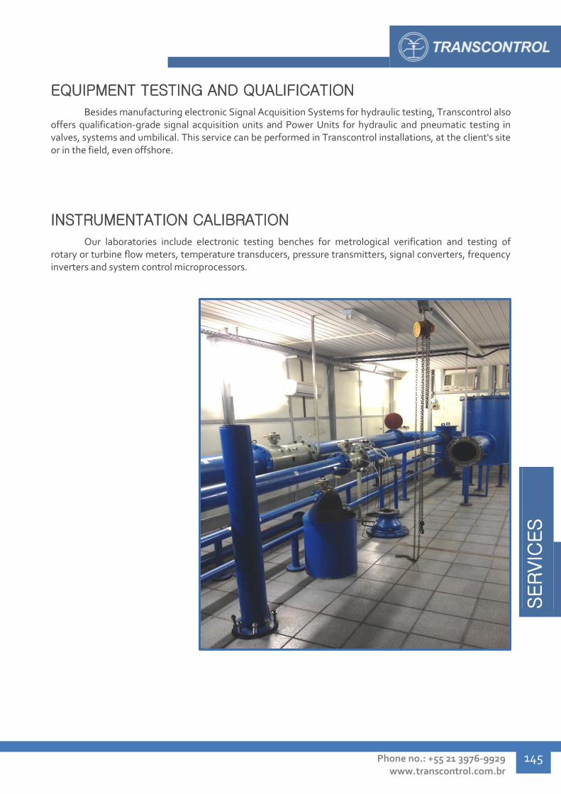
SERVIC
ES
Phone no.: +55 21 3976-9929 www.transcontrol.com.br
145
EQUIPMENT TESTING AND QUALIFICATION
Besides manufacturing electronic Signal Acquisition Systems for hydraulic testing, Transcontrol also offers qualification-grade signal acquisition units and Power Units for hydraulic and pneumatic testing in valves, systems and umbilical. This service can be performed in Transcontrol installations, at the client's site or in the field, even offshore.
INSTRUMENTATION CALIBRATION
Our laboratories include electronic testing benches for metrological verification and testing of rotary or turbine flow meters, temperature transducers, pressure transmitters, signal converters, frequency inverters and system control microprocessors.

SERVIC
ES
Transcontrol Catalog 2016 Edition – Rev. 01
SERVICES
146
SPECIAL MACHINING SERVICES
As an integral part of our manufacturing
process, we employ modern machining equipment
such as Computer Numerical Control (CNC)
machining centers, and conventional machines
operated by a specialized team.
Applying our experience manufacturing
equipment for the industry with rigorous
performance, tolerance and finishing requirements,
we offer special machining services according to the
client's specifications.
HYPERBARIC CHAMBER TESTING
Transcontrol offers testing services for third-party
hydraulic and electric equipment designed for subsea
environment applications. Our laboratories are fitted with
hyperbaric chambers of various sizes, apt for depth
simulation at the pressure levels most commonly required
in subsea designs.
Chamber Maximum pressure Internal dimensions
(work space)
TCH004 4.300 psi Ø835 mm x 1295 mm
TCH006 20.000 psi Ø87.5 mm x 307 mm
60.GE.0055 5.000 psi Ø238 mm x 885 mm

SERVIC
ES
Phone no.: +55 21 3976-9929 www.transcontrol.com.br
147
HYDRAULIC SIGNATURE AND GATE VALVE OVERRIDE (UP TO 1")
TESTING
During test and qualification stages of subsea gate valves, we perform hydraulic signature and override testing on our own facilities, conducted by a specialized and experienced team. We provide the fully furnished laboratories for third-party signature and override test of gate valves of nominal diameter up to 1", and other subsea gate valve qualification tests.
CLADDING SERVICES
In tubing systems for transportation of very aggressive fluids, such as raw oil, it is often more viable, instead of constructing all tube sections with high corrosion resistant alloys – to perform a inlay welding throughout the internal walls of the tubes with a nobler alloy, such as Inconel. This process is called cladding.
Employing modern equipment and a certified, highly capable welding team, Transcontrol offers cladding services using a semi-automatic TIG-Hotwire welding process.
FIELD INSTALLATION SERVICES
We provide our team of highly trained collaborators is apt to perform assembly, installation and test procedures of monitoring and control systems, pressure and temperature transmitters, permanent downhole gauges, among other equipment; and technical services during hydraulic and electric equipment startups procedures, at the client's facilities or offshore platforms.
ÍN
DIC
E G
ERAL
Transcontrol Catalog 2016 Edition – Rev. 01
INDEX
SERVIÇ
OS
148
INDEX
Valves
Ball Valves - TVE ................................................................................................................ 10
Subsea Ball Valves - TVE ..................................................................................................... 18
Needle Valves – TVB .......................................................................................................... 22
High Pressure Needle Valves - THP ...................................................................................... 36
Pressure Relief Valves – TVA ............................................................................................... 40
Gate Valves - TGV .............................................................................................................. 44
Pressure Control Valves - TWO ............................................................................................ 48
High Flow High Pressure Control Valves - TRT ...................................................................... 50
Shuttle Valves - TSV ........................................................................................................... 52
Pneumatic Pilot Valves - TPV .............................................................................................. 56
High-Low Pilot Valves - THL ................................................................................................ 58
Check Valves - TCV ............................................................................................................. 60
High Flow Check Valves - TRV ............................................................................................. 64
Quick Exhaust Valve - TER .................................................................................................. 66
Directional Valves - TVS...................................................................................................... 68
Subsea Directional Valves - TVS .......................................................................................... 72
Piloted Directional Valves - THM ......................................................................................... 74
Auxiliary Hydraulic Instrumentation
Hydraulic Filters - TDA ........................................................................................................ 78
Quick Couplings - TEN ........................................................................................................ 84
Manifolds - TMA ................................................................................................................. 86
Thermal Fuse Plug - TFT ..................................................................................................... 91
Hydropneumatic Pumps - TBO ............................................................................................ 92
Gas Boosters - TBO ............................................................................................................ 94
Transmitters and Data Acquisition
Pressure and Temperature Transmitters – TPT ..................................................................... 98
Permanent Downhole Gauge - PDG ..................................................................................... 106
Downhole Gauge- TTP ........................................................................................................ 110
Coaxial Electrical Cable Splice - TEE ..................................................................................... 112
V-Cone Flow Meter - TMV ................................................................................................... 114
IWIS / Universal PDG Interface Card- TLE............................................................................. 116
Signal Acquisition System (SAS) - TLE ................................................................................. 117
Portable Signal Acquisition System (SASP) - TLE .................................................................. 118

ÍND
ICE G
ERAL
Phone no.: +55 21 3976-9929 www.transcontrol.com.br
149
Mobile Subsea Signal Acquisition System (SSAS) - TSI .......................................................... 119
Independent Subsea Signal Acquisition System (SASMI) - TSI ................................................ 120
Compact Independent Subsea Signal Acquisition System (SASMIcIr) - TSI .............................. 121
Subsea Electrical Monitoring System - TSE ........................................................................... 122
Hydraulic Systems and Components
Quick Unlocking System - TSD ............................................................................................ 126
Hydraulic Plates – TPH ....................................................................................................... 128
Hydraulic Flying Lead – HFL ................................................................................................ 132
Hydraulic Actuators – TSE ................................................................................................... 134
Hot Stab – THS .................................................................................................................. 136
R.O.V. Subsea Control Panels - TPC ..................................................................................... 139
Hydraulic Units and Control Panels – TUF / TPC .................................................................... 140
Services
Hydraulic Power Unit and Control Panel Maintenance ........................................................... 144
Flushing Services ............................................................................................................... 144
Equipment Testing and Qualification ................................................................................... 145
Instrumentation Calibration ................................................................................................ 145
Special Machining Services ................................................................................................. 146
Hyperbaric Chamber Testing ............................................................................................... 146
Hydraulic Signature and Gate Valve Override (up to 1") ......................................................... 147
Cladding Services ............................................................................................................... 147
Field Installation Services ................................................................................................... 147
TRANSCONTROL
Comércio e Indústria de Produtos Eletrônicos Ltda.
Headquarters – Rio de Janeiro
Ourique road, 415, 536 - Penha Circular
CEP 21011-130 – RJ – Brasil
Phone: (+55) 21 3976-9929
Fax: (+55) 21 2560-4416
e-mail: [email protected]
www.transcontrol.com.br

Top Related