


Languages
Pages
Legal

Quintic Software
Tutorial 7c
Intelligent Digitisation
V33
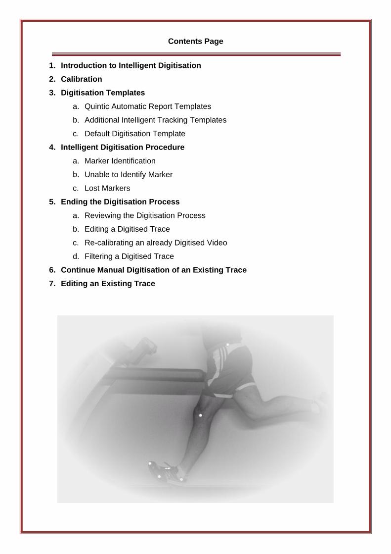
Contents Page
1. Introduction to Intelligent Digitisation
2. Calibration
3. Digitisation Templates
a. Quintic Automatic Report Templates
b. Additional Intelligent Tracking Templates
c. Default Digitisation Template
4. Intelligent Digitisation Procedure
a. Marker Identification
b. Unable to Identify Marker
c. Lost Markers
5. Ending the Digitisation Process
a. Reviewing the Digitisation Process
b. Editing a Digitised Trace
c. Re-calibrating an already Digitised Video
d. Filtering a Digitised Trace
6. Continue Manual Digitisation of an Existing Trace
7. Editing an Existing Trace
1. Introduction to Intelligent Digitisation
Intelligent Digitisation is able to automatically find, relocate and interpolate lost markers
which get obscured or go out the field of view. There is no need for any manual intervention,
making analysis quicker, easier and more accurate than Manual or Automatic Digitisation.
Digitisation allows you to track the location of certain parts of the body or pieces of
equipment throughout the duration of a video clip. Quintic software can then calculate
distances, velocities and accelerations of the points you have tracked.
The 3 different levels of software will allow you to digitise a different number of points:
Quintic Sports v33 – Intelligent Tracking is not available
Quintic Coaching v33 – 2 Point Intelligent Tracking
Quintic Biomechanics v33 – 3 Point Intelligent Tracking or any of our specific
templates we have available for Equine Gait, Human Gait, Cycling or Golf Putting
2. Calibration
To begin digitisation, you must first calibrate the video clip. This means that the computer
can then convert a distance on the computer screen (pixels) to its relative distance in the real
world. Video recording speed also needs to be set so that time-based data e.g. velocity and
acceleration, can also be calculated accurately.
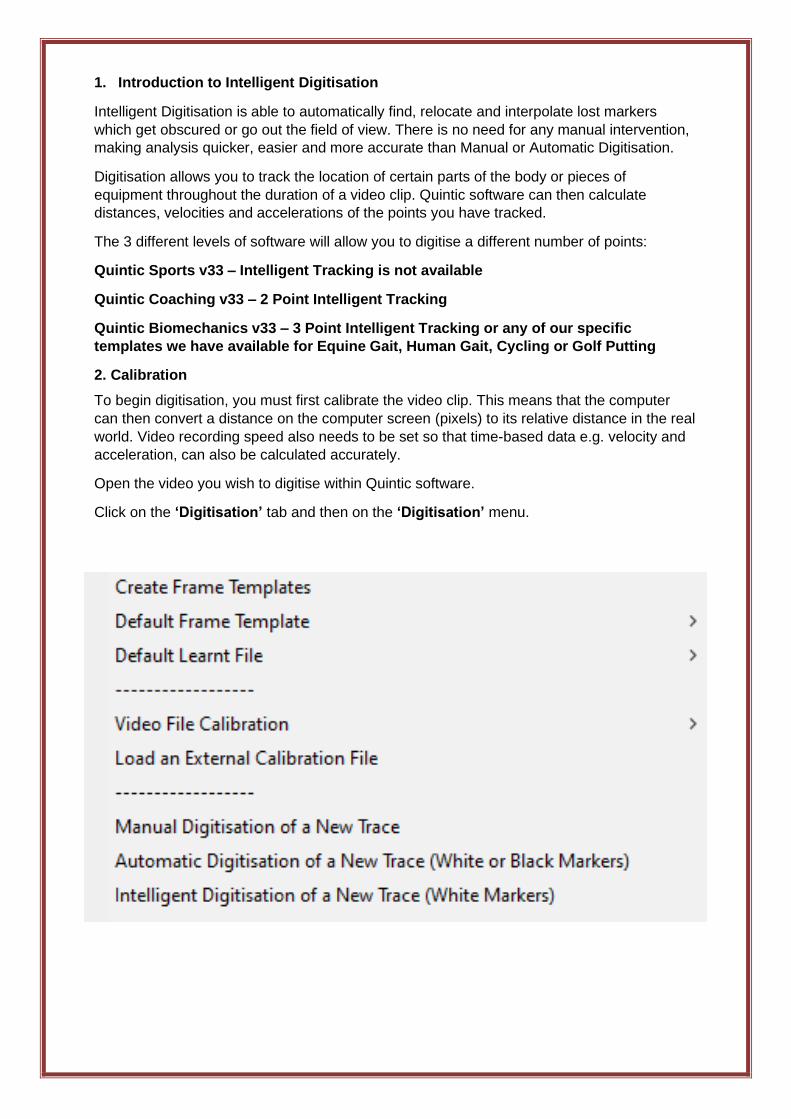
Open the video you wish to digitise within Quintic software.
Click on the ‘Digitisation’ tab and then on the ‘Digitisation’ menu.
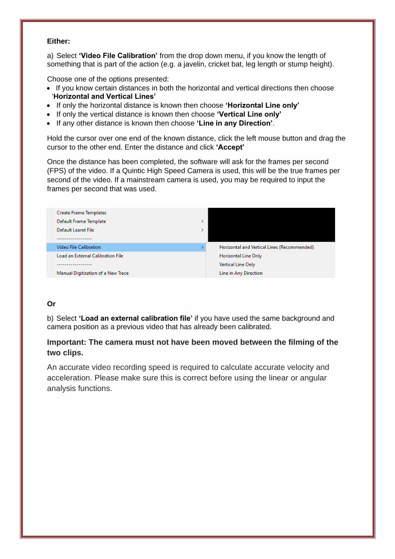
Either:
a) Select ‘Video File Calibration’ from the drop down menu, if you know the length of something that is part of the action (e.g. a javelin, cricket bat, leg length or stump height).
Choose one of the options presented:
• If you know certain distances in both the horizontal and vertical directions then choose ‘Horizontal and Vertical Lines’
• If only the horizontal distance is known then choose ‘Horizontal Line only’
• If only the vertical distance is known then choose ‘Vertical Line only’
• If any other distance is known then choose ‘Line in any Direction’.
Hold the cursor over one end of the known distance, click the left mouse button and drag the
cursor to the other end. Enter the distance and click ‘Accept’
Once the distance has been completed, the software will ask for the frames per second
(FPS) of the video. If a Quintic High Speed Camera is used, this will be the true frames per
second of the video. If a mainstream camera is used, you may be required to input the
frames per second that was used.
Or
b) Select ‘Load an external calibration file’ if you have used the same background and camera position as a previous video that has already been calibrated.
Important: The camera must not have been moved between the filming of the
two clips.
An accurate video recording speed is required to calculate accurate velocity and
acceleration. Please make sure this is correct before using the linear or angular
analysis functions.
3. Digitisation Template
In order to start Intelligent Digitisation, an Intelligent Tracking template must be used. Please
note that the user is unable to create their own Intelligent Tracking template or use any other
template within Intelligent Tracking i.e. Automatic Tracking templates.
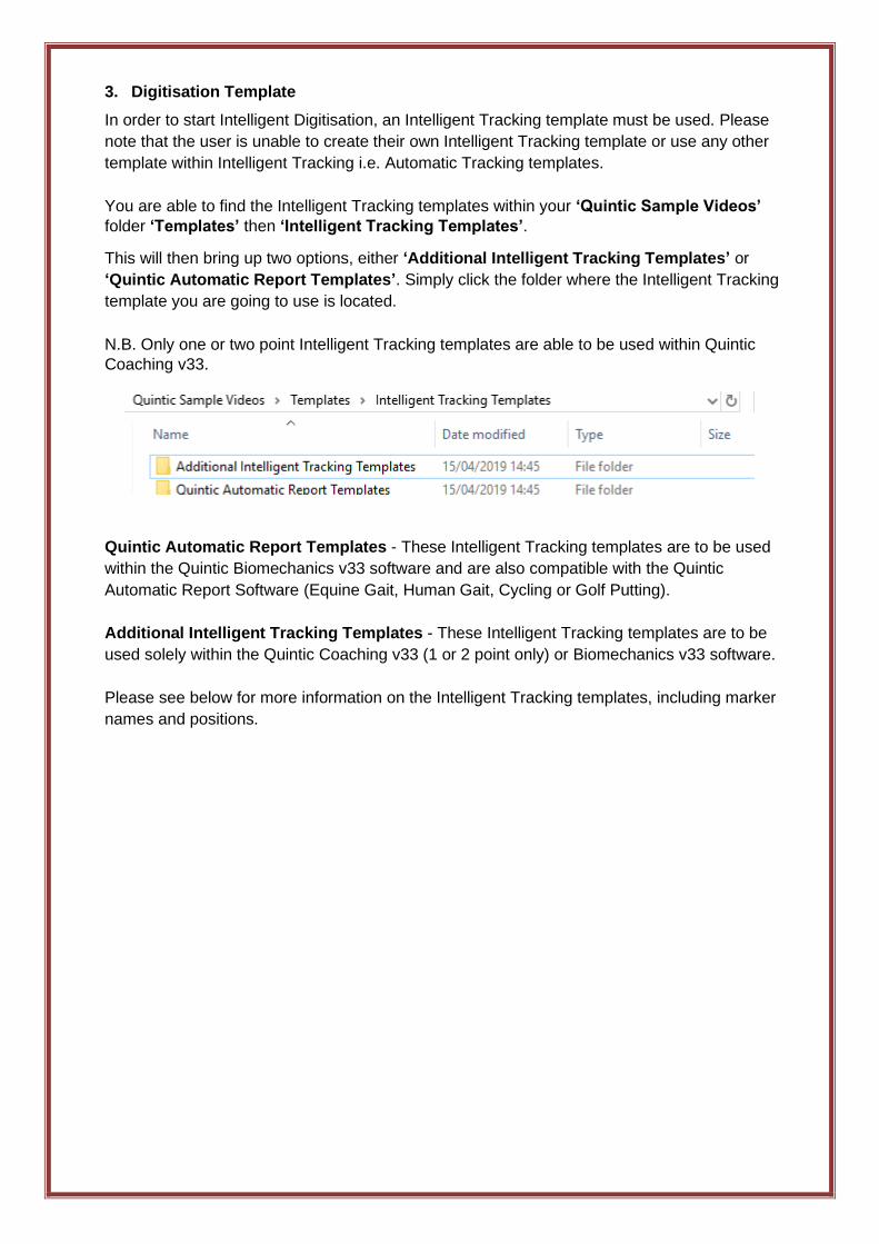
You are able to find the Intelligent Tracking templates within your ‘Quintic Sample Videos’
folder ‘Templates’ then ‘Intelligent Tracking Templates’.
This will then bring up two options, either ‘Additional Intelligent Tracking Templates’ or
‘Quintic Automatic Report Templates’. Simply click the folder where the Intelligent Tracking
template you are going to use is located.
N.B. Only one or two point Intelligent Tracking templates are able to be used within Quintic
Coaching v33.
Quintic Automatic Report Templates - These Intelligent Tracking templates are to be used
within the Quintic Biomechanics v33 software and are also compatible with the Quintic
Automatic Report Software (Equine Gait, Human Gait, Cycling or Golf Putting).
Additional Intelligent Tracking Templates - These Intelligent Tracking templates are to be
used solely within the Quintic Coaching v33 (1 or 2 point only) or Biomechanics v33 software.
Please see below for more information on the Intelligent Tracking templates, including marker
names and positions.
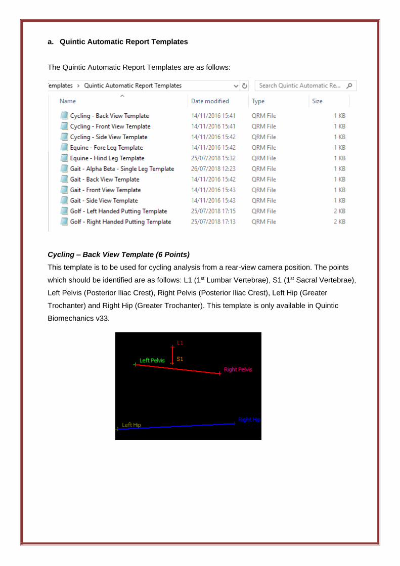
a. Quintic Automatic Report Templates
The Quintic Automatic Report Templates are as follows:
Cycling – Back View Template (6 Points)
This template is to be used for cycling analysis from a rear-view camera position. The points
which should be identified are as follows: L1 (1st Lumbar Vertebrae), S1 (1st Sacral Vertebrae),
Left Pelvis (Posterior Iliac Crest), Right Pelvis (Posterior Iliac Crest), Left Hip (Greater
Trochanter) and Right Hip (Greater Trochanter). This template is only available in Quintic
Biomechanics v33.
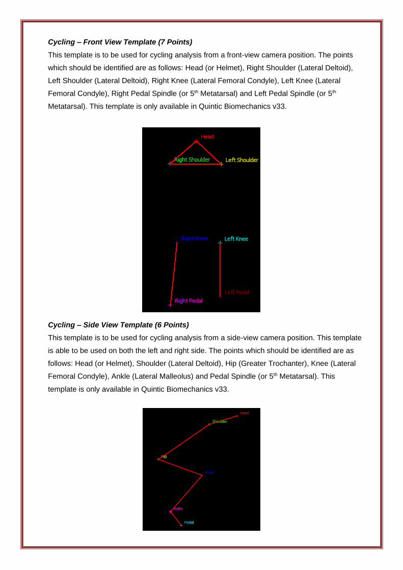
Cycling – Front View Template (7 Points)
This template is to be used for cycling analysis from a front-view camera position. The points
which should be identified are as follows: Head (or Helmet), Right Shoulder (Lateral Deltoid),
Left Shoulder (Lateral Deltoid), Right Knee (Lateral Femoral Condyle), Left Knee (Lateral
Femoral Condyle), Right Pedal Spindle (or 5th Metatarsal) and Left Pedal Spindle (or 5th
Metatarsal). This template is only available in Quintic Biomechanics v33.
Cycling – Side View Template (6 Points)
This template is to be used for cycling analysis from a side-view camera position. This template
is able to be used on both the left and right side. The points which should be identified are as
follows: Head (or Helmet), Shoulder (Lateral Deltoid), Hip (Greater Trochanter), Knee (Lateral
Femoral Condyle), Ankle (Lateral Malleolus) and Pedal Spindle (or 5th Metatarsal). This
template is only available in Quintic Biomechanics v33.
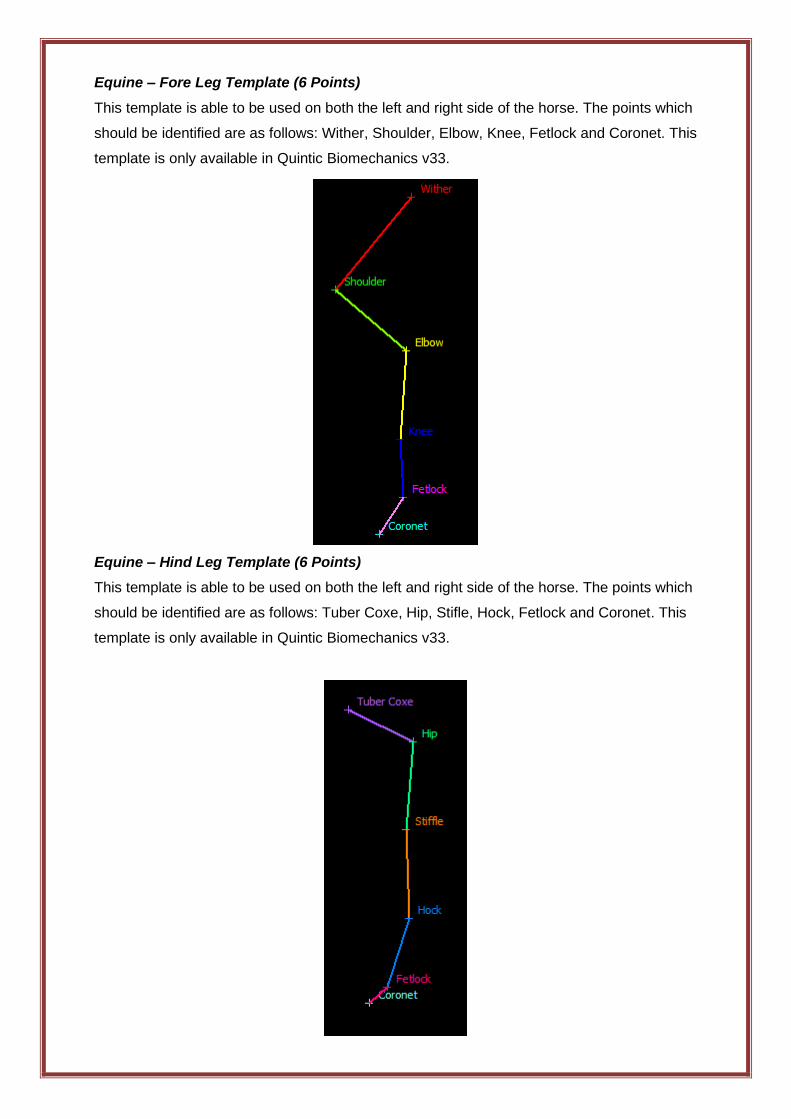
Equine – Fore Leg Template (6 Points)
This template is able to be used on both the left and right side of the horse. The points which
should be identified are as follows: Wither, Shoulder, Elbow, Knee, Fetlock and Coronet. This
template is only available in Quintic Biomechanics v33.
Equine – Hind Leg Template (6 Points)
This template is able to be used on both the left and right side of the horse. The points which
should be identified are as follows: Tuber Coxe, Hip, Stifle, Hock, Fetlock and Coronet. This
template is only available in Quintic Biomechanics v33.
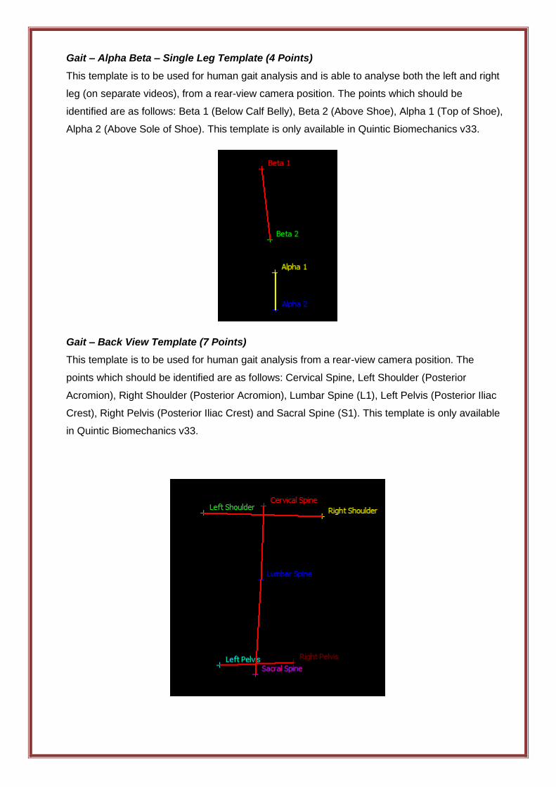
Gait – Alpha Beta – Single Leg Template (4 Points)
This template is to be used for human gait analysis and is able to analyse both the left and right
leg (on separate videos), from a rear-view camera position. The points which should be
identified are as follows: Beta 1 (Below Calf Belly), Beta 2 (Above Shoe), Alpha 1 (Top of Shoe),
Alpha 2 (Above Sole of Shoe). This template is only available in Quintic Biomechanics v33.
Gait – Back View Template (7 Points)
This template is to be used for human gait analysis from a rear-view camera position. The
points which should be identified are as follows: Cervical Spine, Left Shoulder (Posterior
Acromion), Right Shoulder (Posterior Acromion), Lumbar Spine (L1), Left Pelvis (Posterior Iliac
Crest), Right Pelvis (Posterior Iliac Crest) and Sacral Spine (S1). This template is only available
in Quintic Biomechanics v33.

Gait – Front View Template (6 Points)
This template is to be used for human gait analysis and is used to analyse both the left and right
leg at the same time, from a front view camera position. The points which should be identified
are as follows: Right Iliac Crest, Right Patella, Right Distal Tibia, Left Iliac Crest, Left Patella
and Left Distal Tibia. This template is only available in Quintic Biomechanics v33.
Gait – Side View Template (5 Points)
This template is to be used for human gait analysis and can be used to analyse both the left or
right leg, from a side view camera position. The points which should be identified are as follows:
Hip (Greater Trochanter), Knee (Lateral Femoral Condyle), Ankle (Lateral Malleolus), 5th
Metatarsal and Toe (Tip of Shoe). This template is only available in Quintic Biomechanics v33.
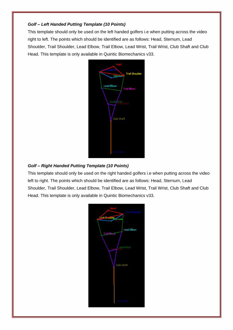
Golf – Left Handed Putting Template (10 Points)
This template should only be used on the left handed golfers i.e when putting across the video
right to left. The points which should be identified are as follows: Head, Sternum, Lead
Shoulder, Trail Shoulder, Lead Elbow, Trail Elbow, Lead Wrist, Trail Wrist, Club Shaft and Club
Head. This template is only available in Quintic Biomechanics v33.
Golf – Right Handed Putting Template (10 Points)
This template should only be used on the right handed golfers i.e when putting across the video
left to right. The points which should be identified are as follows: Head, Sternum, Lead
Shoulder, Trail Shoulder, Lead Elbow, Trail Elbow, Lead Wrist, Trail Wrist, Club Shaft and Club
Head. This template is only available in Quintic Biomechanics v33.
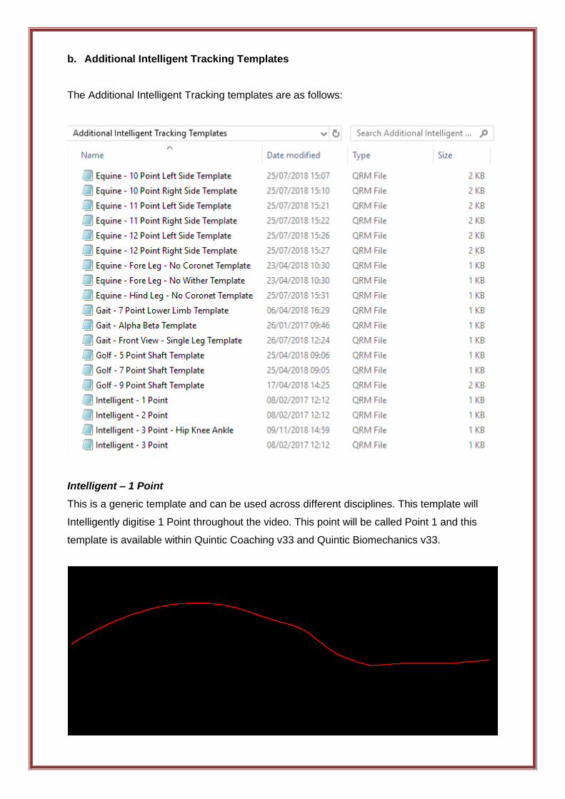
b. Additional Intelligent Tracking Templates
The Additional Intelligent Tracking templates are as follows:
Intelligent – 1 Point
This is a generic template and can be used across different disciplines. This template will
Intelligently digitise 1 Point throughout the video. This point will be called Point 1 and this
template is available within Quintic Coaching v33 and Quintic Biomechanics v33.
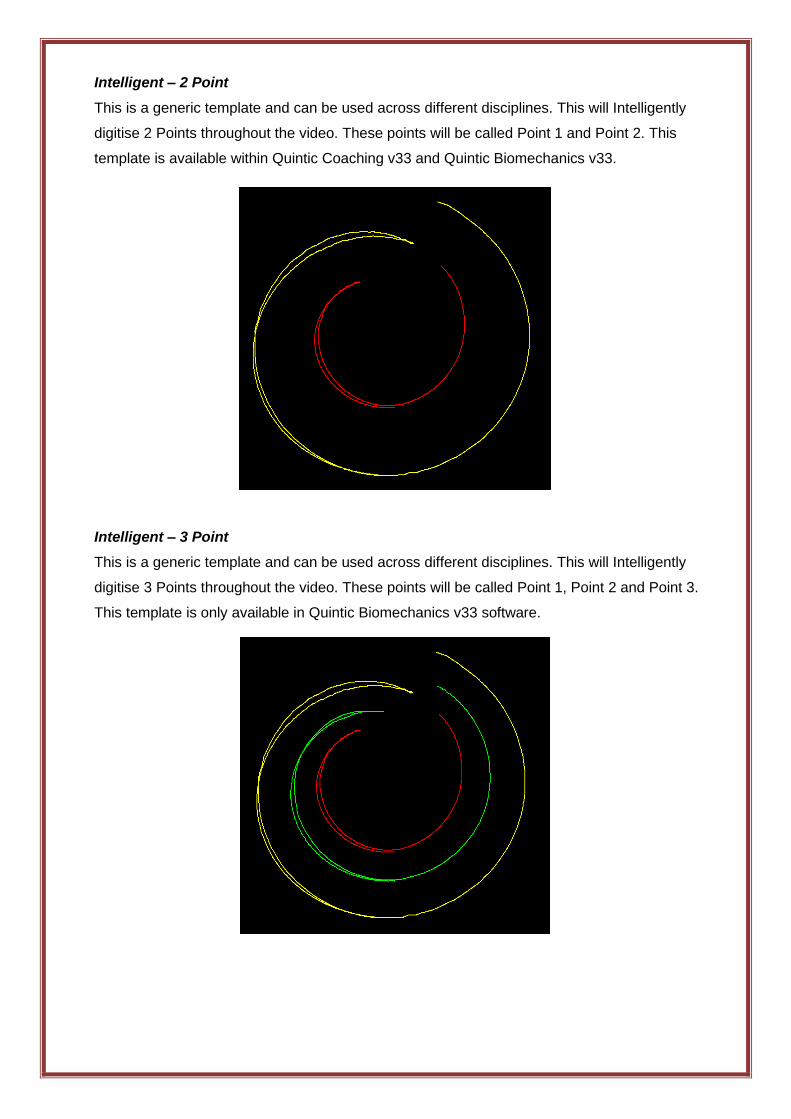
Intelligent – 2 Point
This is a generic template and can be used across different disciplines. This will Intelligently
digitise 2 Points throughout the video. These points will be called Point 1 and Point 2. This
template is available within Quintic Coaching v33 and Quintic Biomechanics v33.
Intelligent – 3 Point
This is a generic template and can be used across different disciplines. This will Intelligently
digitise 3 Points throughout the video. These points will be called Point 1, Point 2 and Point 3.
This template is only available in Quintic Biomechanics v33 software.
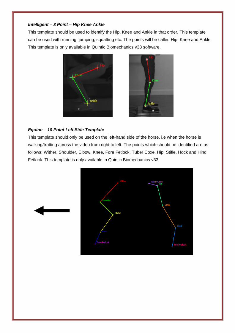
Intelligent – 3 Point – Hip Knee Ankle
This template should be used to identify the Hip, Knee and Ankle in that order. This template
can be used with running, jumping, squatting etc. The points will be called Hip, Knee and Ankle.
This template is only available in Quintic Biomechanics v33 software.
Equine – 10 Point Left Side Template
This template should only be used on the left-hand side of the horse, i.e when the horse is
walking/trotting across the video from right to left. The points which should be identified are as
follows: Wither, Shoulder, Elbow, Knee, Fore Fetlock, Tuber Coxe, Hip, Stifle, Hock and Hind
Fetlock. This template is only available in Quintic Biomechanics v33.
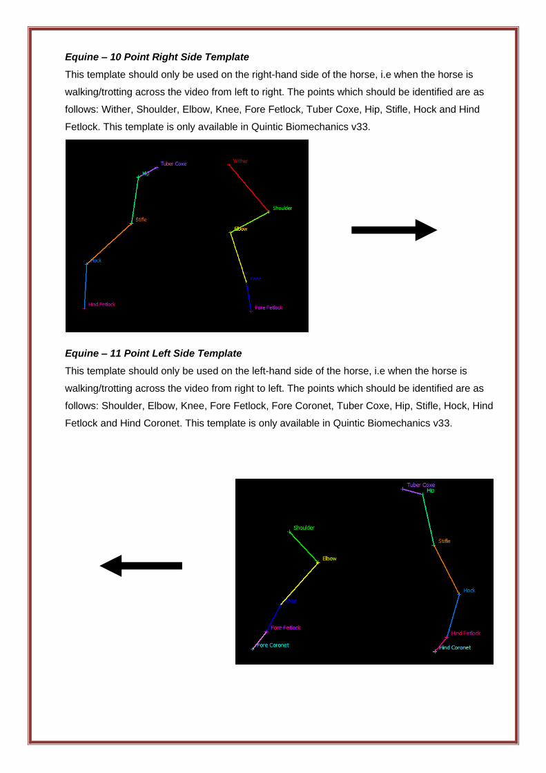
Equine – 10 Point Right Side Template
This template should only be used on the right-hand side of the horse, i.e when the horse is
walking/trotting across the video from left to right. The points which should be identified are as
follows: Wither, Shoulder, Elbow, Knee, Fore Fetlock, Tuber Coxe, Hip, Stifle, Hock and Hind
Fetlock. This template is only available in Quintic Biomechanics v33.
Equine – 11 Point Left Side Template
This template should only be used on the left-hand side of the horse, i.e when the horse is
walking/trotting across the video from right to left. The points which should be identified are as
follows: Shoulder, Elbow, Knee, Fore Fetlock, Fore Coronet, Tuber Coxe, Hip, Stifle, Hock, Hind
Fetlock and Hind Coronet. This template is only available in Quintic Biomechanics v33.
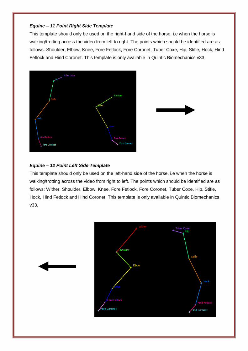
Equine – 11 Point Right Side Template
This template should only be used on the right-hand side of the horse, i.e when the horse is
walking/trotting across the video from left to right. The points which should be identified are as
follows: Shoulder, Elbow, Knee, Fore Fetlock, Fore Coronet, Tuber Coxe, Hip, Stifle, Hock, Hind
Fetlock and Hind Coronet. This template is only available in Quintic Biomechanics v33.
Equine – 12 Point Left Side Template
This template should only be used on the left-hand side of the horse, i.e when the horse is
walking/trotting across the video from right to left. The points which should be identified are as
follows: Wither, Shoulder, Elbow, Knee, Fore Fetlock, Fore Coronet, Tuber Coxe, Hip, Stifle,
Hock, Hind Fetlock and Hind Coronet. This template is only available in Quintic Biomechanics
v33.
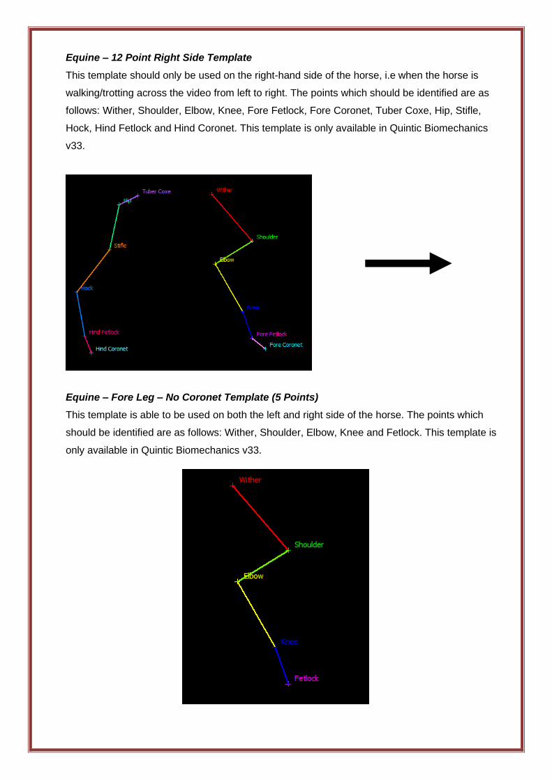
Equine – 12 Point Right Side Template
This template should only be used on the right-hand side of the horse, i.e when the horse is
walking/trotting across the video from left to right. The points which should be identified are as
follows: Wither, Shoulder, Elbow, Knee, Fore Fetlock, Fore Coronet, Tuber Coxe, Hip, Stifle,
Hock, Hind Fetlock and Hind Coronet. This template is only available in Quintic Biomechanics
v33.
Equine – Fore Leg – No Coronet Template (5 Points)
This template is able to be used on both the left and right side of the horse. The points which
should be identified are as follows: Wither, Shoulder, Elbow, Knee and Fetlock. This template is
only available in Quintic Biomechanics v33.
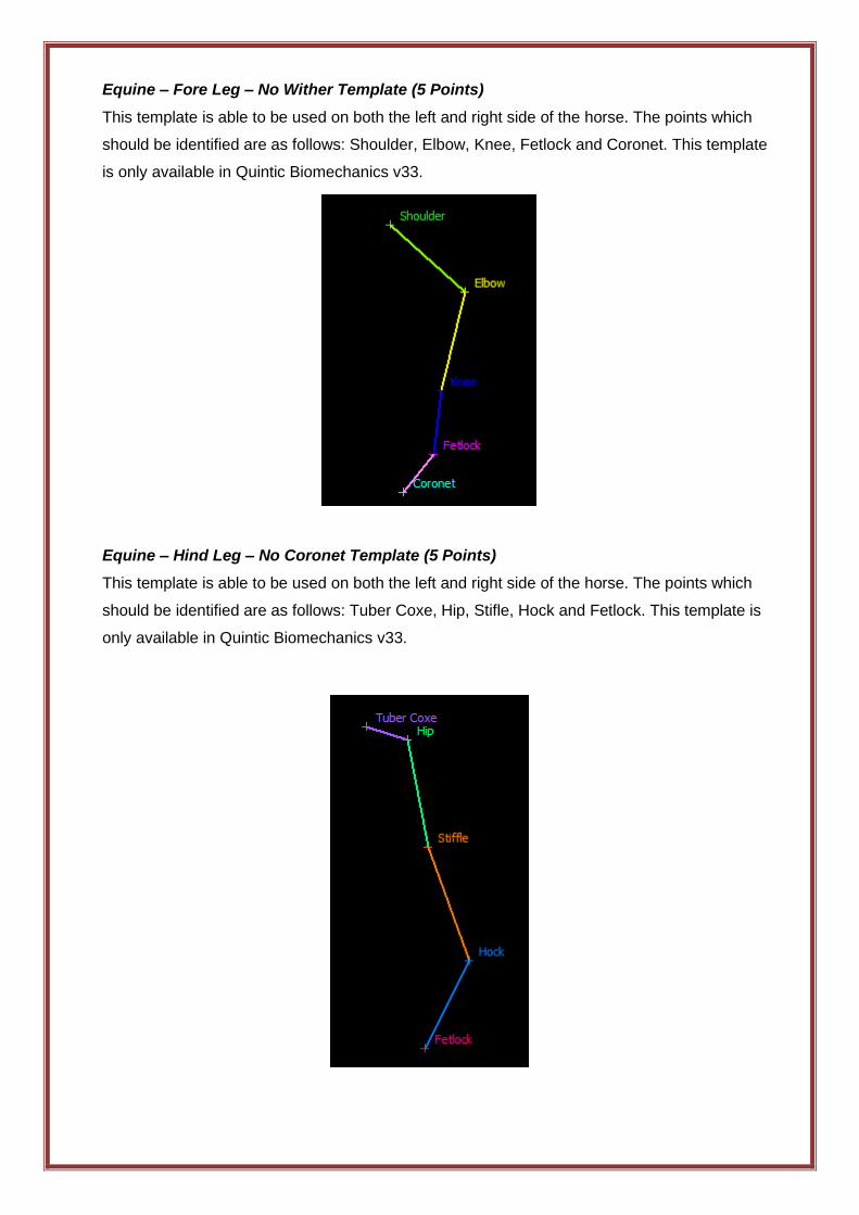
Equine – Fore Leg – No Wither Template (5 Points)
This template is able to be used on both the left and right side of the horse. The points which
should be identified are as follows: Shoulder, Elbow, Knee, Fetlock and Coronet. This template
is only available in Quintic Biomechanics v33.
Equine – Hind Leg – No Coronet Template (5 Points)
This template is able to be used on both the left and right side of the horse. The points which
should be identified are as follows: Tuber Coxe, Hip, Stifle, Hock and Fetlock. This template is
only available in Quintic Biomechanics v33.
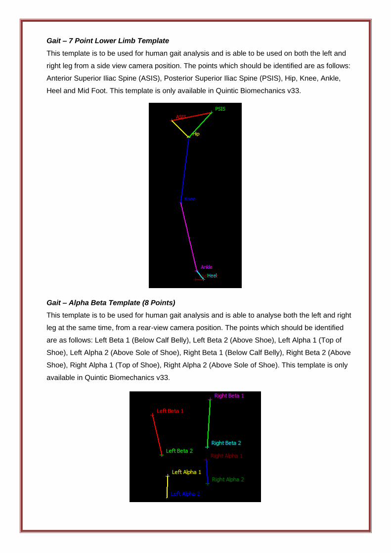
Gait – 7 Point Lower Limb Template
This template is to be used for human gait analysis and is able to be used on both the left and
right leg from a side view camera position. The points which should be identified are as follows:
Anterior Superior Iliac Spine (ASIS), Posterior Superior Iliac Spine (PSIS), Hip, Knee, Ankle,
Heel and Mid Foot. This template is only available in Quintic Biomechanics v33.
Gait – Alpha Beta Template (8 Points)
This template is to be used for human gait analysis and is able to analyse both the left and right
leg at the same time, from a rear-view camera position. The points which should be identified
are as follows: Left Beta 1 (Below Calf Belly), Left Beta 2 (Above Shoe), Left Alpha 1 (Top of
Shoe), Left Alpha 2 (Above Sole of Shoe), Right Beta 1 (Below Calf Belly), Right Beta 2 (Above
Shoe), Right Alpha 1 (Top of Shoe), Right Alpha 2 (Above Sole of Shoe). This template is only
available in Quintic Biomechanics v33.
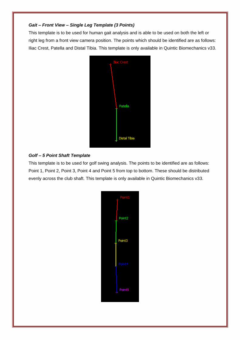
Gait – Front View – Single Leg Template (3 Points)
This template is to be used for human gait analysis and is able to be used on both the left or
right leg from a front view camera position. The points which should be identified are as follows:
Iliac Crest, Patella and Distal Tibia. This template is only available in Quintic Biomechanics v33.
Golf – 5 Point Shaft Template
This template is to be used for golf swing analysis. The points to be identified are as follows:
Point 1, Point 2, Point 3, Point 4 and Point 5 from top to bottom. These should be distributed
evenly across the club shaft. This template is only available in Quintic Biomechanics v33.
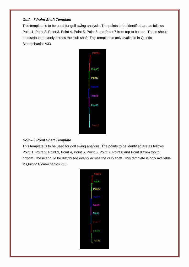
Golf – 7 Point Shaft Template
This template is to be used for golf swing analysis. The points to be identified are as follows:
Point 1, Point 2, Point 3, Point 4, Point 5, Point 6 and Point 7 from top to bottom. These should
be distributed evenly across the club shaft. This template is only available in Quintic
Biomechanics v33.
Golf – 9 Point Shaft Template
This template is to be used for golf swing analysis. The points to be identified are as follows:
Point 1, Point 2, Point 3, Point 4, Point 5, Point 6, Point 7, Point 8 and Point 9 from top to
bottom. These should be distributed evenly across the club shaft. This template is only available
in Quintic Biomechanics v33.
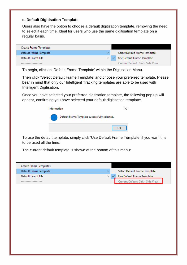
c. Default Digitisation Template
Users also have the option to choose a default digitisation template, removing the need
to select it each time. Ideal for users who use the same digitisation template on a
regular basis.
To begin, click on ‘Default Frame Template’ within the Digitisation Menu.
Then click ‘Select Default Frame Template’ and choose your preferred template. Please
bear in mind that only our Intelligent Tracking templates are able to be used with
Intelligent Digitisation.
Once you have selected your preferred digitisation template, the following pop up will
appear, confirming you have selected your default digitisation template:
To use the default template, simply click ‘Use Default Frame Template’ if you want this
to be used all the time.
The current default template is shown at the bottom of this menu:
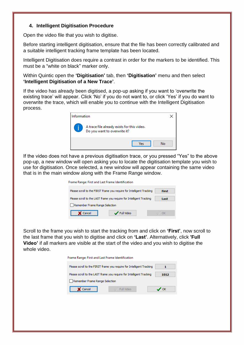
4. Intelligent Digitisation Procedure
Open the video file that you wish to digitise.
Before starting intelligent digitisation, ensure that the file has been correctly calibrated and
a suitable intelligent tracking frame template has been located.
Intelligent Digitisation does require a contrast in order for the markers to be identified. This
must be a “white on black” marker only.
Within Quintic open the ‘Digitisation’ tab, then ‘Digitisation’ menu and then select
‘Intelligent Digitisation of a New Trace’.
If the video has already been digitised, a pop-up asking if you want to ‘overwrite the existing trace’ will appear. Click ‘No’ if you do not want to, or click ‘Yes’ if you do want to overwrite the trace, which will enable you to continue with the Intelligent Digitisation process.
If the video does not have a previous digitisation trace, or you pressed “Yes” to the above pop-up, a new window will open asking you to locate the digitisation template you wish to use for digitisation. Once selected, a new window will appear containing the same video that is in the main window along with the Frame Range window.
Scroll to the frame you wish to start the tracking from and click on ‘First’, now scroll to
the last frame that you wish to digitise and click on ‘Last’. Alternatively, click 'Full
Video’ if all markers are visible at the start of the video and you wish to digitise the
whole video.
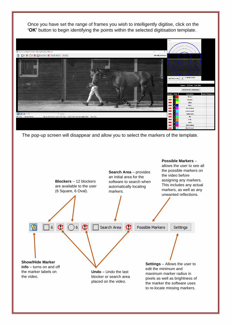
Once you have set the range of frames you wish to intelligently digitise, click on the
‘OK’ button to begin identifying the points within the selected digitisation template.
The pop-up screen will disappear and allow you to select the markers of the template.
Blockers – 12 blockers
are available to the user
(6 Square, 6 Oval).
Undo – Undo the last
blocker or search area
placed on the video.
Search Area – provides
an initial area for the
software to search when
automatically locating
markers.
Show/Hide Marker
info – turns on and off
the marker labels on
the video.
Settings – Allows the user to
edit the minimum and
maximum marker radius in
pixels as well as brightness of
the marker the software uses
to re-locate missing markers.
Possible Markers –
allows the user to see all
the possible markers on
the video before
assigning any markers.
This includes any actual
markers, as well as any
unwanted reflections.
a. Marker Identification
• Blockers – The blockers can be used to block out distracting features of the video
such as lights or reflective objects that may be confused for markers. If a marker is
lost during the blocked region, that marker would be unable to be reidentified in that
blocked region. However, they do not obscure markers that are being tracked by
the software. Tracked markers can pass through blocked areas without affecting the
final digitised trace.
• Search Area – The search area directs the software where to look during auto
detection of markers. If a search area is not drawn the software will use the whole
image.
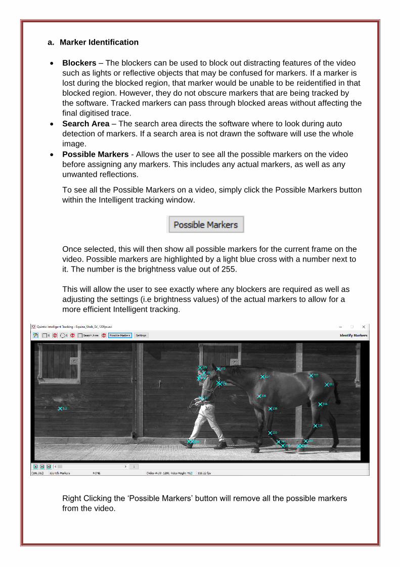
• Possible Markers - Allows the user to see all the possible markers on the video
before assigning any markers. This includes any actual markers, as well as any
unwanted reflections.
To see all the Possible Markers on a video, simply click the Possible Markers button
within the Intelligent tracking window.
Once selected, this will then show all possible markers for the current frame on the
video. Possible markers are highlighted by a light blue cross with a number next to
it. The number is the brightness value out of 255.
This will allow the user to see exactly where any blockers are required as well as
adjusting the settings (i.e brightness values) of the actual markers to allow for a
more efficient Intelligent tracking.
Right Clicking the ‘Possible Markers’ button will remove all the possible markers
from the video.
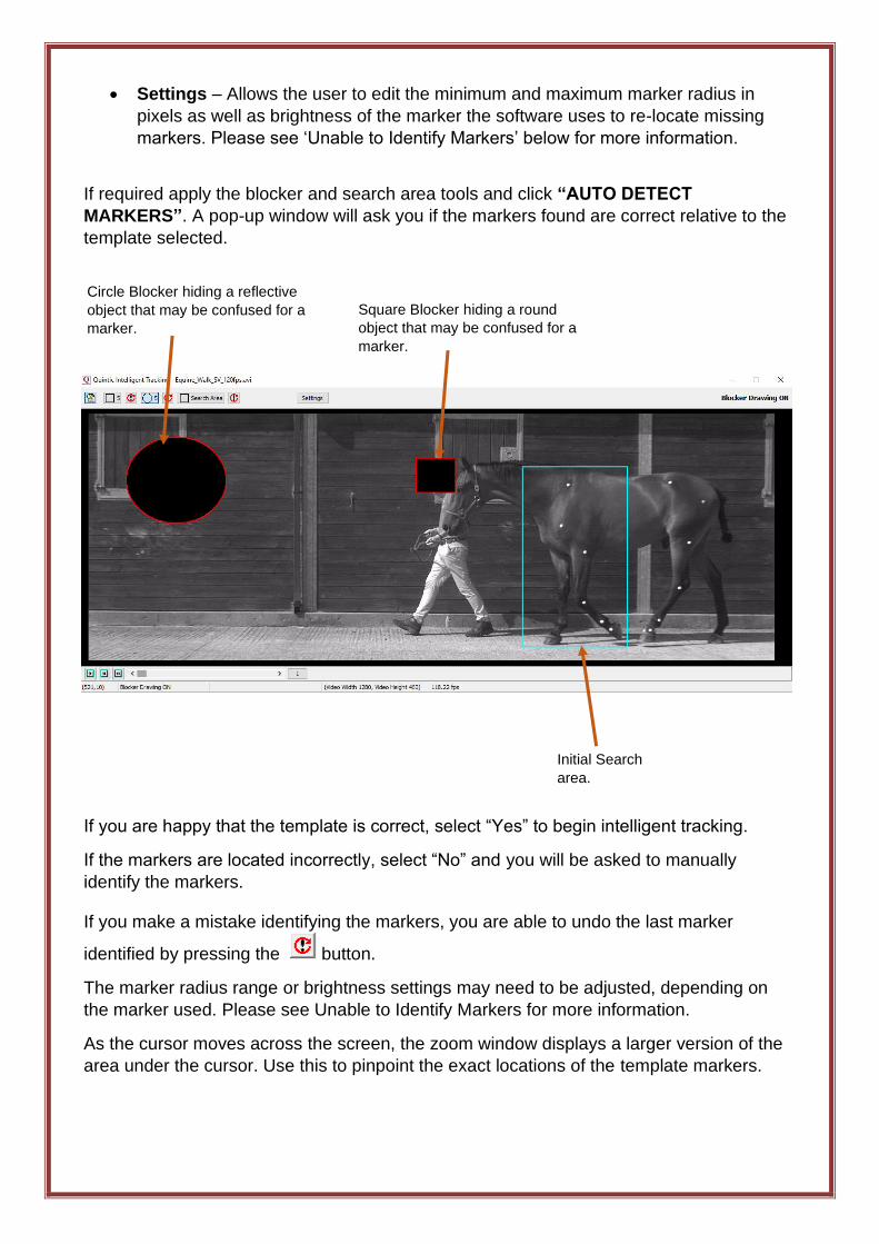
• Settings – Allows the user to edit the minimum and maximum marker radius in
pixels as well as brightness of the marker the software uses to re-locate missing
markers. Please see ‘Unable to Identify Markers’ below for more information.
If required apply the blocker and search area tools and click “AUTO DETECT
MARKERS”. A pop-up window will ask you if the markers found are correct relative to the
template selected.
If you are happy that the template is correct, select “Yes” to begin intelligent tracking.
If the markers are located incorrectly, select “No” and you will be asked to manually
identify the markers.
If you make a mistake identifying the markers, you are able to undo the last marker
identified by pressing the button.
The marker radius range or brightness settings may need to be adjusted, depending on
the marker used. Please see Unable to Identify Markers for more information.
As the cursor moves across the screen, the zoom window displays a larger version of the
area under the cursor. Use this to pinpoint the exact locations of the template markers.
Circle Blocker hiding a reflective
object that may be confused for a
marker.
Square Blocker hiding a round
object that may be confused for a
marker.
Initial Search
area.
This must be done in the correct order and as accurately as possible. As the point is
assigned to a landmark, the next point will automatically be selected and ready to be
assigned. If the symbol next to the point description is yellow this indicates the marker
needs to be identified.
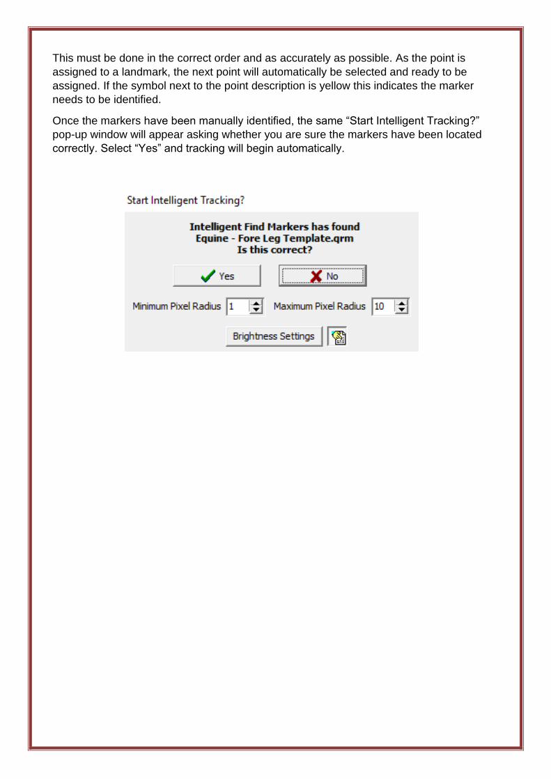
Once the markers have been manually identified, the same “Start Intelligent Tracking?”
pop-up window will appear asking whether you are sure the markers have been located
correctly. Select “Yes” and tracking will begin automatically.
b. Unable to Identify Marker
During the marker identification process if you are unable to identify a marker, you may
be able to adjust the settings to change the marker range radius and brightness of the
marker. This could potentially help to identify markers that you were unable to
previously identify.
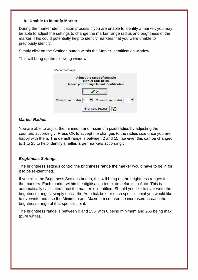
Simply click on the Settings button within the Marker Identification window.
This will bring up the following window.
Marker Radius
You are able to adjust the minimum and maximum pixel radius by adjusting the
counters accordingly. Press OK to accept the changes to the radius size once you are
happy with them. The default range is between 2 and 15, however this can be changed
to 1 to 25 to help identify smaller/larger markers accordingly.
Brightness Settings
The brightness settings control the brightness range the marker would have to be in for
it to be re-identified.
If you click the Brightness Settings button, this will bring up the brightness ranges for
the markers. Each marker within the digitisation template defaults to Auto. This is
automatically calculated once the marker is identified. Should you like to over write the
brightness ranges, simply untick the Auto tick box for each specific point you would like
to overwrite and use the Minimum and Maximum counters to increase/decrease the
brightness range of that specific point.
The brightness range is between 0 and 255, with 0 being minimum and 255 being max
(pure white).
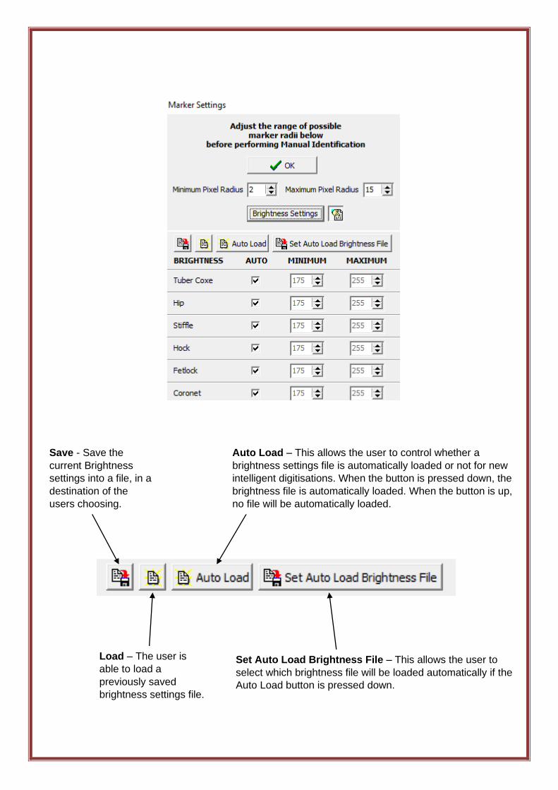
Save - Save the
current Brightness
settings into a file, in a
destination of the
users choosing.
Load – The user is
able to load a
previously saved
brightness settings file.
Auto Load – This allows the user to control whether a
brightness settings file is automatically loaded or not for new
intelligent digitisations. When the button is pressed down, the
brightness file is automatically loaded. When the button is up,
no file will be automatically loaded.
Set Auto Load Brightness File – This allows the user to
select which brightness file will be loaded automatically if the
Auto Load button is pressed down.
c. Lost Markers
During digitisation a marker can be “lost”; obstructed by equipment or limbs, or leave the
Area of Interest (AOI). With intelligent tracking Quintic is able to recognise the marker
when it reappears from behind the obstruction.
Once the tracking has started, you do not have to do anything until the video has played
through.
5. Ending the Intelligent Digitisation Process
To end Intelligent Digitisation, either let the video digitise until the last digitisation frame
you selected has been reached, it’s the end of the video or the ‘Stop Tracking’ button has
been pressed.
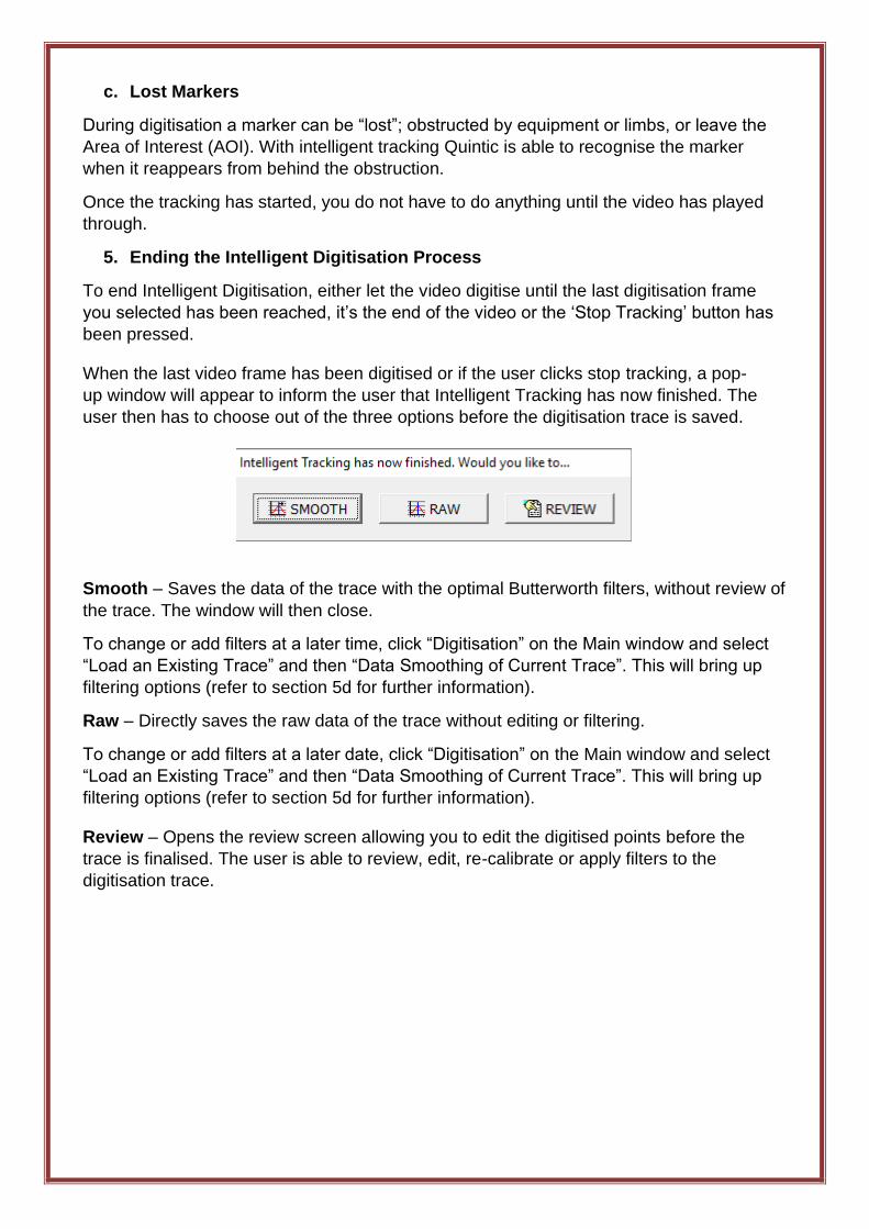
When the last video frame has been digitised or if the user clicks stop tracking, a pop-
up window will appear to inform the user that Intelligent Tracking has now finished. The
user then has to choose out of the three options before the digitisation trace is saved.
Smooth – Saves the data of the trace with the optimal Butterworth filters, without review of
the trace. The window will then close.
To change or add filters at a later time, click “Digitisation” on the Main window and select
“Load an Existing Trace” and then “Data Smoothing of Current Trace”. This will bring up
filtering options (refer to section 5d for further information).
Raw – Directly saves the raw data of the trace without editing or filtering.
To change or add filters at a later date, click “Digitisation” on the Main window and select
“Load an Existing Trace” and then “Data Smoothing of Current Trace”. This will bring up
filtering options (refer to section 5d for further information).
Review – Opens the review screen allowing you to edit the digitised points before the
trace is finalised. The user is able to review, edit, re-calibrate or apply filters to the
digitisation trace.
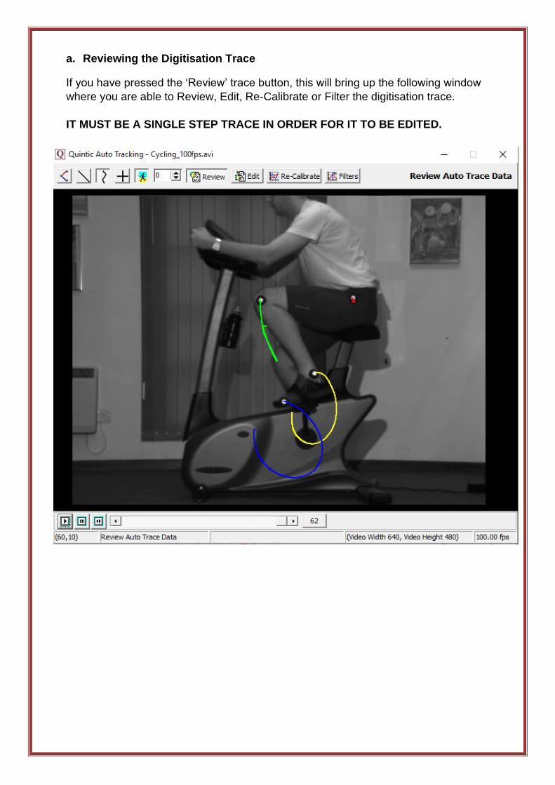
a. Reviewing the Digitisation Trace
If you have pressed the ‘Review’ trace button, this will bring up the following window
where you are able to Review, Edit, Re-Calibrate or Filter the digitisation trace.
IT MUST BE A SINGLE STEP TRACE IN ORDER FOR IT TO BE EDITED.
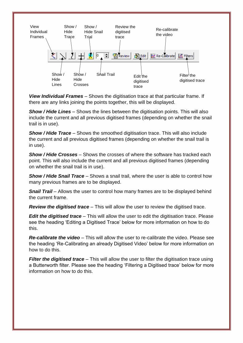
View Individual Frames – Shows the digitisation trace at that particular frame. If
there are any links joining the points together, this will be displayed.
Show / Hide Lines – Shows the lines between the digitisation points. This will also
include the current and all previous digitised frames (depending on whether the snail
trail is in use).
Show / Hide Trace – Shows the smoothed digitisation trace. This will also include
the current and all previous digitised frames (depending on whether the snail trail is
in use).
Show / Hide Crosses – Shows the crosses of where the software has tracked each
point. This will also include the current and all previous digitised frames (depending
on whether the snail trail is in use).
Show / Hide Snail Trace – Shows a snail trail, where the user is able to control how
many previous frames are to be displayed.
Snail Trail – Allows the user to control how many frames are to be displayed behind
the current frame.
Review the digitised trace – This will allow the user to review the digitised trace.
Edit the digitised trace – This will allow the user to edit the digitisation trace. Please
see the heading ‘Editing a Digitised Trace’ below for more information on how to do
this.
Re-calibrate the video – This will allow the user to re-calibrate the video. Please see
the heading ‘Re-Calibrating an already Digitised Video’ below for more information on
how to do this.
Filter the digitised trace – This will allow the user to filter the digitisation trace using
a Butterworth filter. Please see the heading ‘Filtering a Digitised trace’ below for more
information on how to do this.
View
Individual
Frames
Show /
Hide
Lines
Show /
Hide
Trace
Show /
Hide
Crosses
Show /
Hide Snail
Trial
Snail Trail
Review the
digitised
trace
Edit the
digitised
trace
Re-calibrate
the video
Filter the
digitised trace
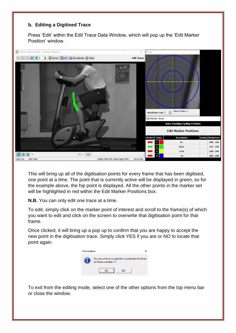
b. Editing a Digitised Trace
Press ‘Edit’ within the Edit Trace Data Window, which will pop up the ‘Edit Marker
Position’ window.
This will bring up all of the digitisation points for every frame that has been digitised,
one point at a time. The point that is currently active will be displayed in green, so for
the example above, the hip point is displayed. All the other points in the marker set
will be highlighted in red within the Edit Marker Positions box.
N.B. You can only edit one trace at a time.
To edit, simply click on the marker point of interest and scroll to the frame(s) of which
you want to edit and click on the screen to overwrite that digitisation point for that
frame.
Once clicked, it will bring up a pop up to confirm that you are happy to accept the
new point in the digitisation trace. Simply click YES if you are or NO to locate that
point again.
To exit from the editing mode, select one of the other options from the top menu bar
or close the window.
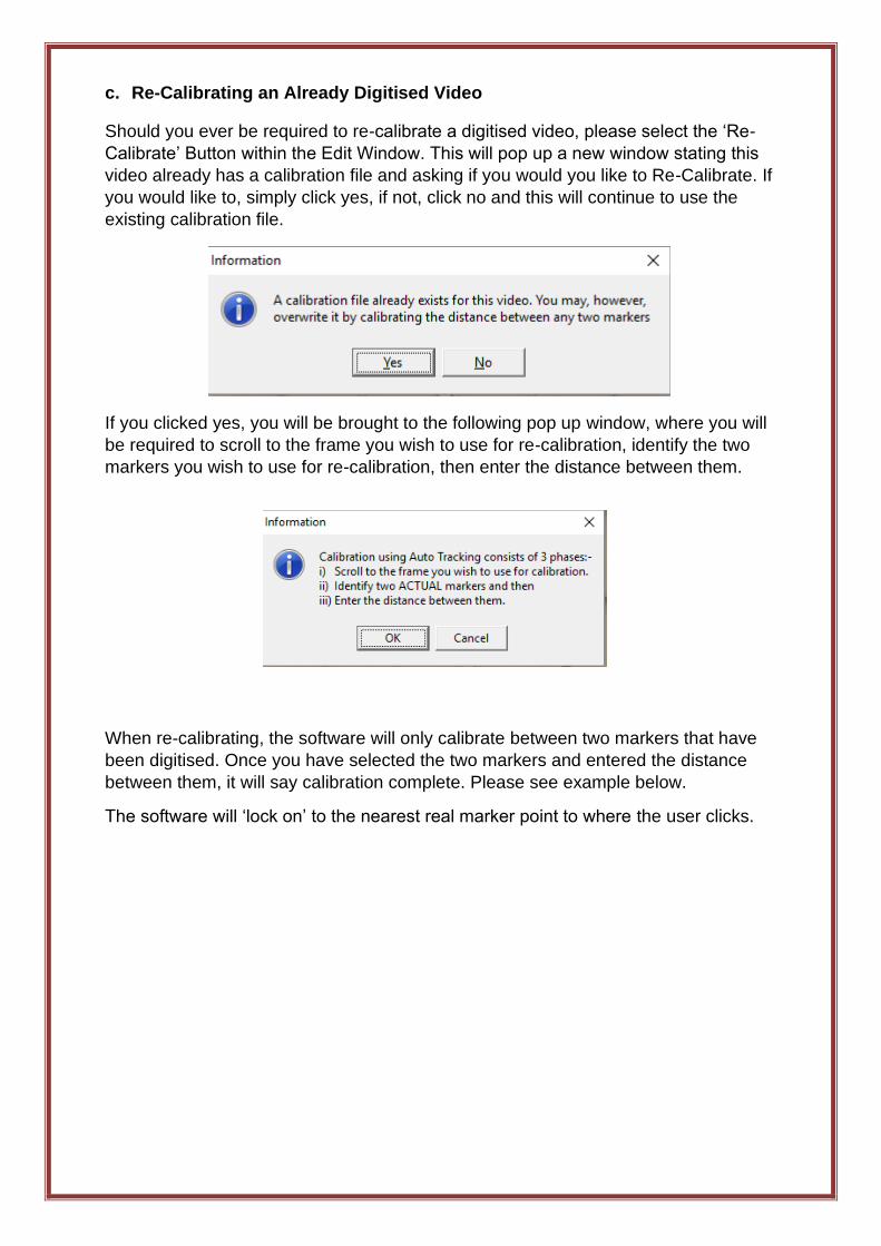
c. Re-Calibrating an Already Digitised Video
Should you ever be required to re-calibrate a digitised video, please select the ‘Re-
Calibrate’ Button within the Edit Window. This will pop up a new window stating this
video already has a calibration file and asking if you would you like to Re-Calibrate. If
you would like to, simply click yes, if not, click no and this will continue to use the
existing calibration file.
If you clicked yes, you will be brought to the following pop up window, where you will
be required to scroll to the frame you wish to use for re-calibration, identify the two
markers you wish to use for re-calibration, then enter the distance between them.
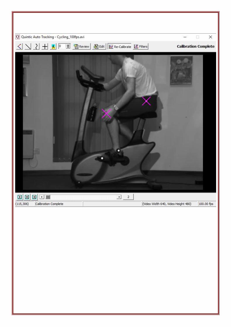
When re-calibrating, the software will only calibrate between two markers that have
been digitised. Once you have selected the two markers and entered the distance
between them, it will say calibration complete. Please see example below.
The software will ‘lock on’ to the nearest real marker point to where the user clicks.
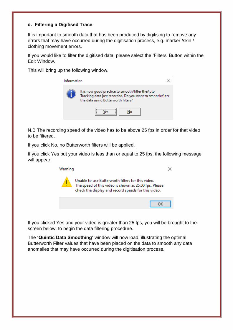
d. Filtering a Digitised Trace
It is important to smooth data that has been produced by digitising to remove any
errors that may have occurred during the digitisation process, e.g. marker /skin /
clothing movement errors.
If you would like to filter the digitised data, please select the ‘Filters’ Button within the
Edit Window.
This will bring up the following window.
N.B The recording speed of the video has to be above 25 fps in order for that video
to be filtered.
If you click No, no Butterworth filters will be applied.
If you click Yes but your video is less than or equal to 25 fps, the following message
will appear.
If you clicked Yes and your video is greater than 25 fps, you will be brought to the
screen below, to begin the data filtering procedure.
The ‘Quintic Data Smoothing’ window will now load, illustrating the optimal
Butterworth Filter values that have been placed on the data to smooth any data
anomalies that may have occurred during the digitisation process.
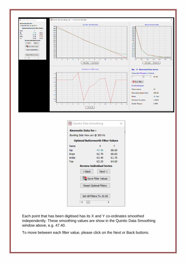
Each point that has been digitised has its X and Y co-ordinates smoothed
independently. These smoothing values are show in the Quintic Data Smoothing
window above, e.g. 47.40.
To move between each filter value, please click on the Next or Back buttons.
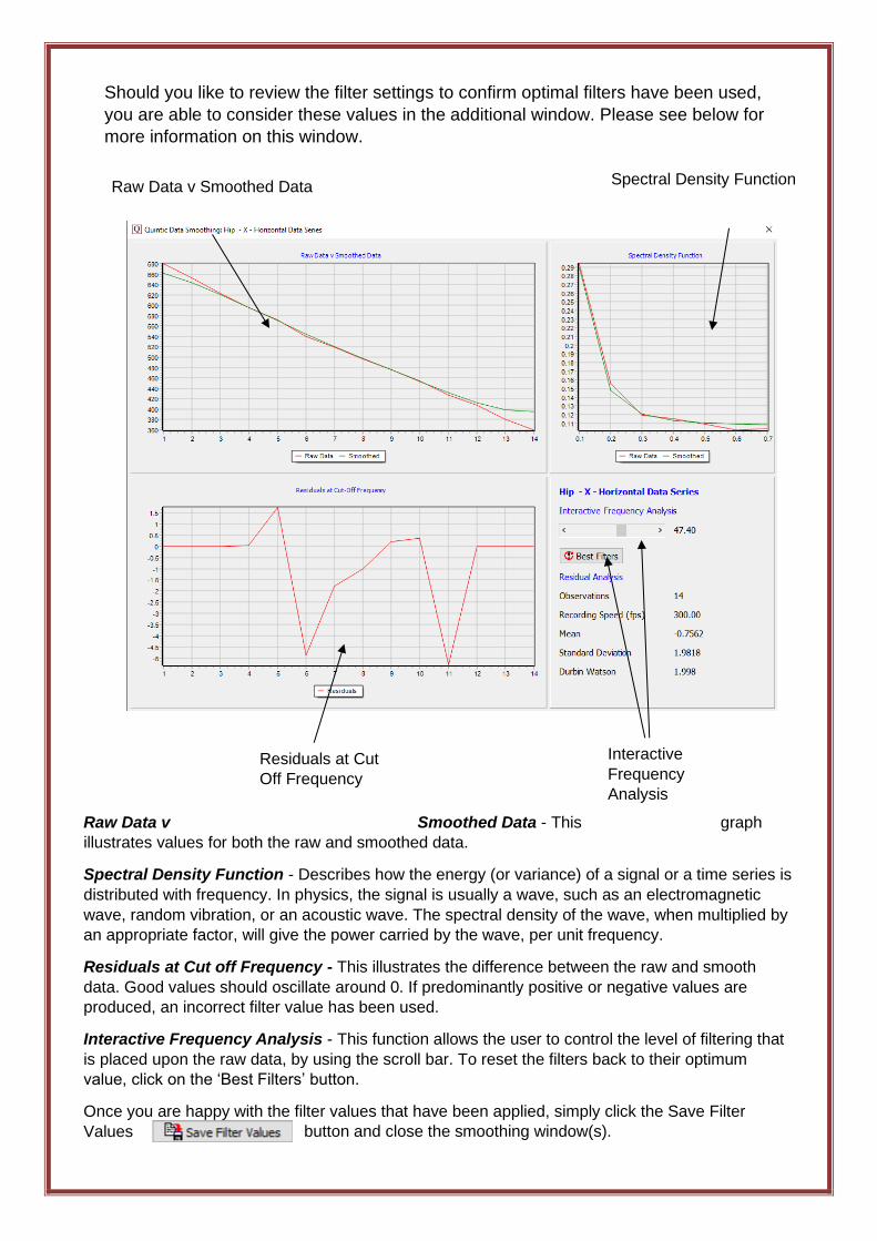
Should you like to review the filter settings to confirm optimal filters have been used,
you are able to consider these values in the additional window. Please see below for
more information on this window.
Raw Data v Smoothed Data - This graph
illustrates values for both the raw and smoothed data.
Spectral Density Function - Describes how the energy (or variance) of a signal or a time series is
distributed with frequency. In physics, the signal is usually a wave, such as an electromagnetic
wave, random vibration, or an acoustic wave. The spectral density of the wave, when multiplied by
an appropriate factor, will give the power carried by the wave, per unit frequency.
Residuals at Cut off Frequency - This illustrates the difference between the raw and smooth
data. Good values should oscillate around 0. If predominantly positive or negative values are
produced, an incorrect filter value has been used.
Interactive Frequency Analysis - This function allows the user to control the level of filtering that
is placed upon the raw data, by using the scroll bar. To reset the filters back to their optimum
value, click on the ‘Best Filters’ button.
Once you are happy with the filter values that have been applied, simply click the Save Filter
Values button and close the smoothing window(s).
Raw Data v Smoothed Data Spectral Density Function
Residuals at Cut
Off Frequency
Interactive
Frequency
Analysis
6. Continue Manual Digitisation of an Existing Trace
You are able to save a digitisation trace and then carry on Manually digitising it at a later
time. This can be done by clicking the Digitisation button within the Digitisation tab, then
clicking ‘Continue Manual Digitisation of an Existing Trace’.
This will allow the user to carry on digitising from the next frame after the last frame
previously digitised. Please note, you are unable to re-edit previously digitised traces within
this window.
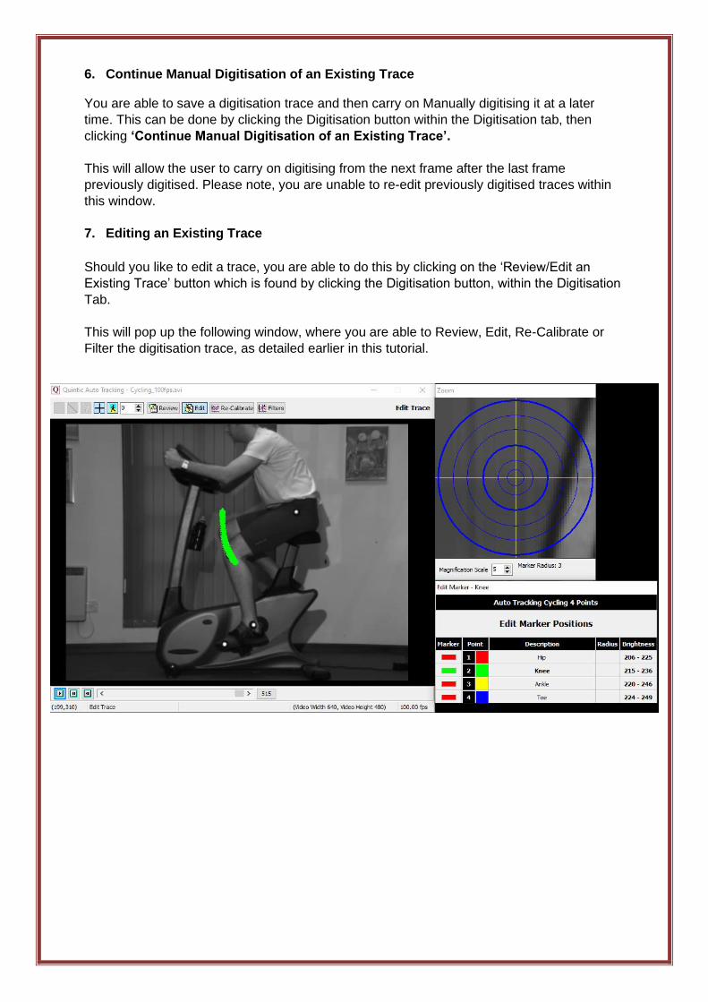
7. Editing an Existing Trace
Should you like to edit a trace, you are able to do this by clicking on the ‘Review/Edit an
Existing Trace’ button which is found by clicking the Digitisation button, within the Digitisation
Tab.
This will pop up the following window, where you are able to Review, Edit, Re-Calibrate or
Filter the digitisation trace, as detailed earlier in this tutorial.
Top Related