


Languages
Pages
Legal

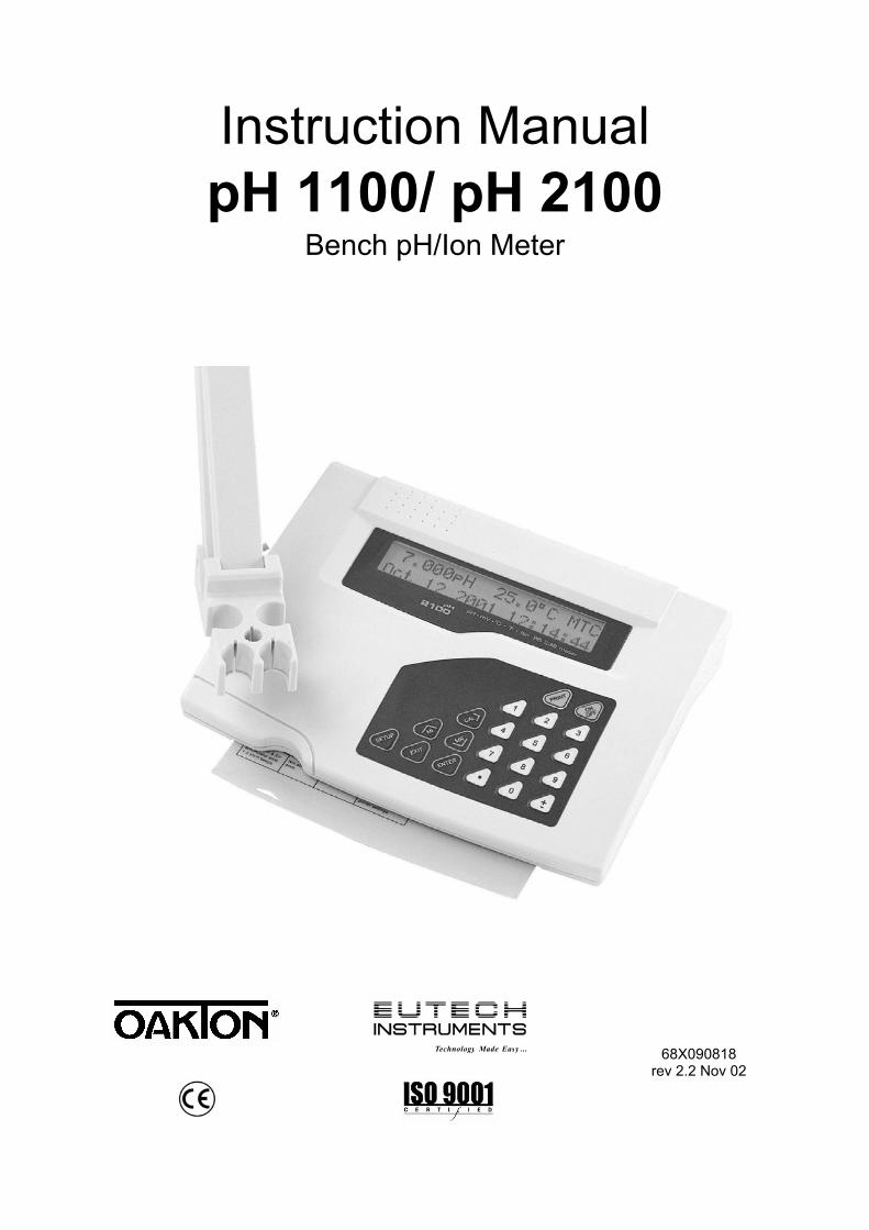
Instruction Manual pH 1100/ pH 2100
Bench pH/Ion Meter
Technology Made Easy ... 68X090818 rev 2.2 Nov 02

CyberScan pH 1100/ 2100
PREFACE Thank you for selecting the pH 1100/ 2100 benchtop meter. This meter measure pH, millivolts, relative millivolts and temperature. The pH 2100 meter also measures ion concentration. The instruction manual serves to explain the use of the pH 1100/ 2100 bench meter as a step-by-step operational guide to help you familiarize with the meter’s features and functions. It is structured sequentially with illustration of diagrams that explains the various functions and setup menus available. This manual is written to cover as many anticipated applications and uses of the pH 1100/ 2100 Bench meter as possible. If there are doubts in the use of the meter, please do not hesitate to contact the nearest Authorized Distributor or Customer Service Dept. for assistance. Eutech Instruments/ Oakton Instruments reserve the rights to change, make improvement and modify specifications without prior notice and cannot accept any responsibility for damage or malfunction to the instrument caused by improper use. Copyright © 2002 Eutech Instruments Pte. Ltd. Oakton Instruments All rights reserved. Revision 2.2, Nov 02.
Instruction Manual CyberScan pH 1100/ 2100
4
TABLE OF CONTENTS 1 INTRODUCTION 6
1.1 Introducing the Bench Meter Series 6 1.2 Keypad 7 1.3 Rear Panel 8 1.4 Electrode Holder 9
2 STARTING UP 10 2.1 Back Panel Connections 10 2.2 Powering up and powering down 10
2.2.1 Powering up 10 2.2.2 Powering down 10
3 PH CALIBRATION & MEASUREMENT 11 3.1 pH calibration 11
3.1.1 Automatic Temperature Compensation (ATC) 11 3.1.2 Starting pH calibration 12 3.1.3 Standard pH buffer calibration 13 3.1.4 Custom pH buffer calibration 14 3.1.5 Calibration error messages 15
3.2 pH measurement 16 3.2.1 Automatic temperature compensation 16 3.2.2 Adjusting manual temperature compensation 16 3.2.3 Taking pH Measurements 17
4 mV CALIBRATION AND MEASUREMENT 18 4.1 mV Calibration 18
4.1.1 mV Calibration error message 18 4.2 mV Measurement 19
5 ION CALIBRATION AND MEASUREMENT (ONLY APPLICABLE FOR pH 2100) 20 5.1 Ion calibration 20 5.2 Ion calibration error messages 21 5.3 Ion measurement 22
6 MEMORY FUNCTIONS 23 6.1 Memory input 23
6.1.1 Manually storing a reading into memory 23 6.2 Memory recall 24
6.2.1 Recalling readings in manual recall mode 24 6.2.2 Recalling readings in automatic recall mode 24
7 STABILITY INDICATOR 25 8 ALARM FUNCTIONS 25
8.1 High and Low measurement alarm 25 8.2 Calibration due alarm 25
9 TEMPERATURE CALIBRATION 26 9.1 Temperature Calibration 26 9.2 Temperature Calibration Error Messages 26
10 SETUP MODE 27 10.1 Setup mode overview 27
10.1.1 pH/Temperature setup submenus 27 10.1.2 mV setup submenus 28 10.1.3 Ion setup submenus (pH 2100 only) 28 10.1.4 Meter general configuration setup submenus 29
10.2 pH/ temperature setup mode 30 10.2.1 Entering pH/temperature setup mode 30 10.2.2 pH buffer setup program P1.0 30 10.2.3 pH resolution setup program P1.1 31 10.2.4 Temperature unit setup program P1.2 31 10.2.5 pH Measurement Alarm Setup Program P1.3 32 10.2.6 pH Calibration Due Alarm Setup program P1.4 33 10.2.7 Stability Setup Program P1.5 34 10.2.8 View pH calibration data setup program P1.6 35
Instruction Manual CyberScan pH 1100/ 2100
5
10.2.9 pH calibration data reset setup program P1.7 36 10.3 mV setup mode 37
10.3.1 Entering mV setup mode 37 10.3.2 mV measurement alarm setup program P2.0 38 10.3.3 mV calibration due alarm setup program P2.1 39 10.3.4 Stability setup program P2.2 40 10.3.5 View mV calibration data setup program P2.3 41 10.3.6 mV calibration data reset setup program P2.4 42
10.4 Ion setup mode (pH 2100 meter only) 43 10.4.1 Entering ion setup mode 43 10.4.2 Ion unit setup mode P3.0 43 10.4.3 Ion measurement alarm setup program P3.1 44 10.4.4 Ion calibration due alarm setup program P3.2 45 10.4.5 Stability setup program P3.3 46 10.4.6 Ion mode setup program P3.4 47 10.4.7 View ion calibration data setup program P3.5 48 10.4.8 Ion calibration data reset setup program P3.6 49
10.5 Meter general configuration setup mode 50 10.5.1 Entering meter general setup mode 50 10.5.2 Date/time setup mode P4.0 50 10.5.3 Backlight setup mode P4.1 51 10.5.4 Data log setup mode P4.2 52 10.5.5 Memory recall setup mode P4.3 52 10.5.6 Communication setup mode P4.4 53 10.5.7 Data transfer setup mode P4.5 53 10.5.8 Memory clear setup mode P4.6 54 10.5.9 Meter reset setup mode P4.7 54
11 ELECTRODE CARE 55 11.1 Electrode Activation 55 11.2 Electrode Maintenance 55 11.3 Storing pH/ORP electrodes 55
12 RS 232 COMMUNICATION 56 12.1 Using with printer 56
12.1.1 Sending data to printer 56 12.2 Using with computer 56
13 ADDITIONAL INFORMATION 57 13.1 pH and Temperature 57 13.2 pH Buffer Calibration Solution 57 13.3 Standard pH Buffers 57
14 SUMMARY OF DEFAULT SETTINGS / OPTIONS 58 15 TROUBLESHOOTING & ERROR MESSAGES 59 16 SPECIFICATIONS 60 17 ACCESSORIES 61 18 WARRANTY 62
Instruction Manual CyberScan pH 1100/ 2100
6
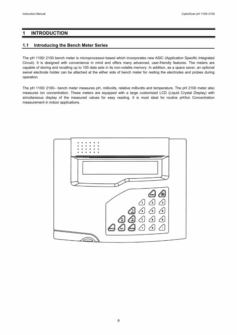
1 INTRODUCTION 1.1 Introducing the Bench Meter Series The pH 1100/ 2100 bench meter is microprocessor-based which incorporates new ASIC (Application Specific Integrated Circuit). It is designed with convenience in mind and offers many advanced, user-friendly features. The meters are capable of storing and recalling up to 100 data sets in its non-volatile memory. In addition, as a space saver, an optional swivel electrode holder can be attached at the either side of bench meter for resting the electrodes and probes during operation. The pH 1100/ 2100-- bench meter measures pH, millivolts, relative millivolts and temperature. The pH 2100 meter also measures ion concentration. These meters are equipped with a large customized LCD (Liquid Crystal Display) with simultaneous display of the measured values for easy reading. It is most ideal for routine pH/Ion Concentration measurement in indoor applications.
Instruction Manual CyberScan pH 1100/ 2100
7
1.2 Keypad
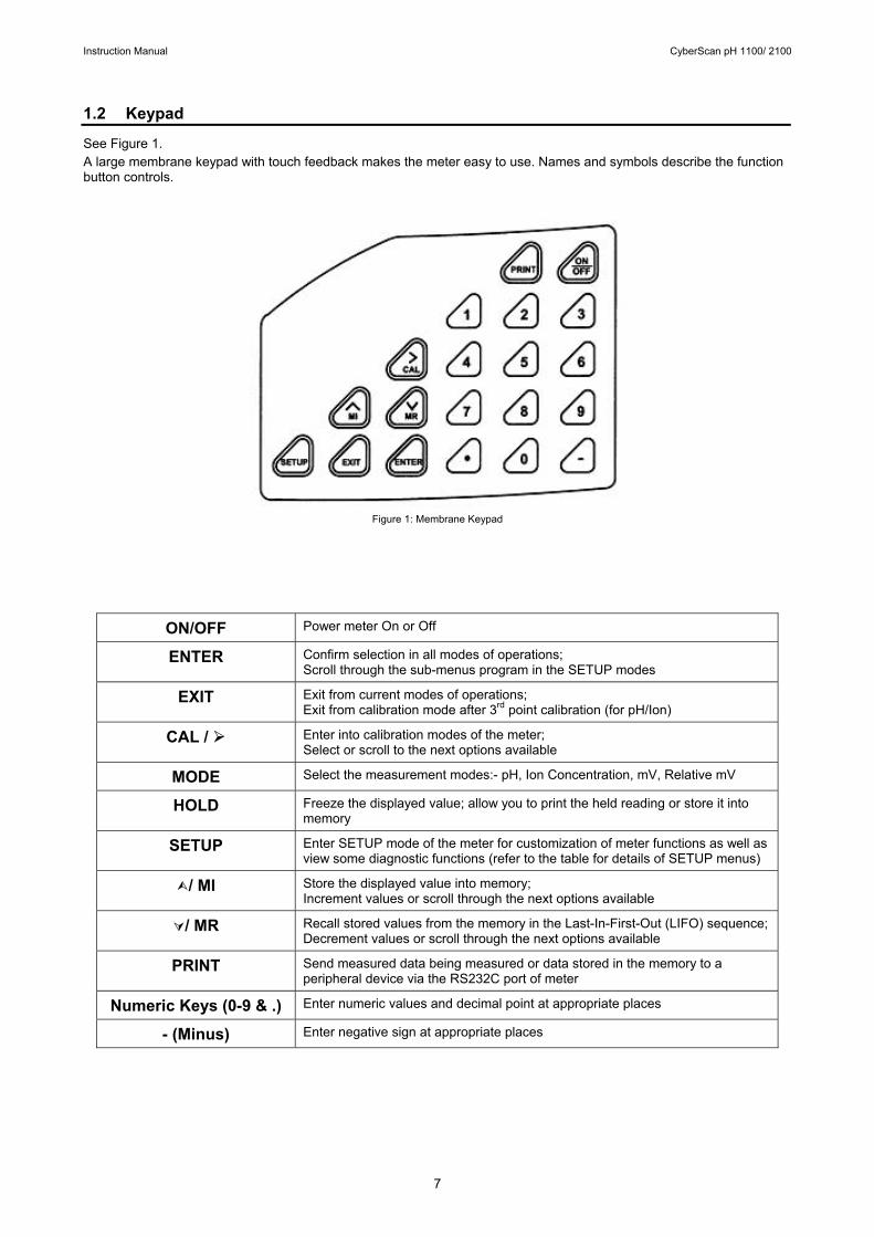
See Figure 1. A large membrane keypad with touch feedback makes the meter easy to use. Names and symbols describe the function button controls.
Figure 1: Membrane Keypad
ON/OFF Power meter On or Off
ENTER Confirm selection in all modes of operations; Scroll through the sub-menus program in the SETUP modes
EXIT Exit from current modes of operations; Exit from calibration mode after 3rd point calibration (for pH/Ion)
CAL / Enter into calibration modes of the meter; Select or scroll to the next options available
MODE Select the measurement modes:- pH, Ion Concentration, mV, Relative mV
HOLD Freeze the displayed value; allow you to print the held reading or store it into memory
SETUP Enter SETUP mode of the meter for customization of meter functions as well as view some diagnostic functions (refer to the table for details of SETUP menus)
/ MI Store the displayed value into memory; Increment values or scroll through the next options available
/ MR Recall stored values from the memory in the Last-In-First-Out (LIFO) sequence; Decrement values or scroll through the next options available
PRINT Send measured data being measured or data stored in the memory to a peripheral device via the RS232C port of meter
Numeric Keys (0-9 & .) Enter numeric values and decimal point at appropriate places
- (Minus) Enter negative sign at appropriate places
Instruction Manual CyberScan pH 1100/ 2100
8
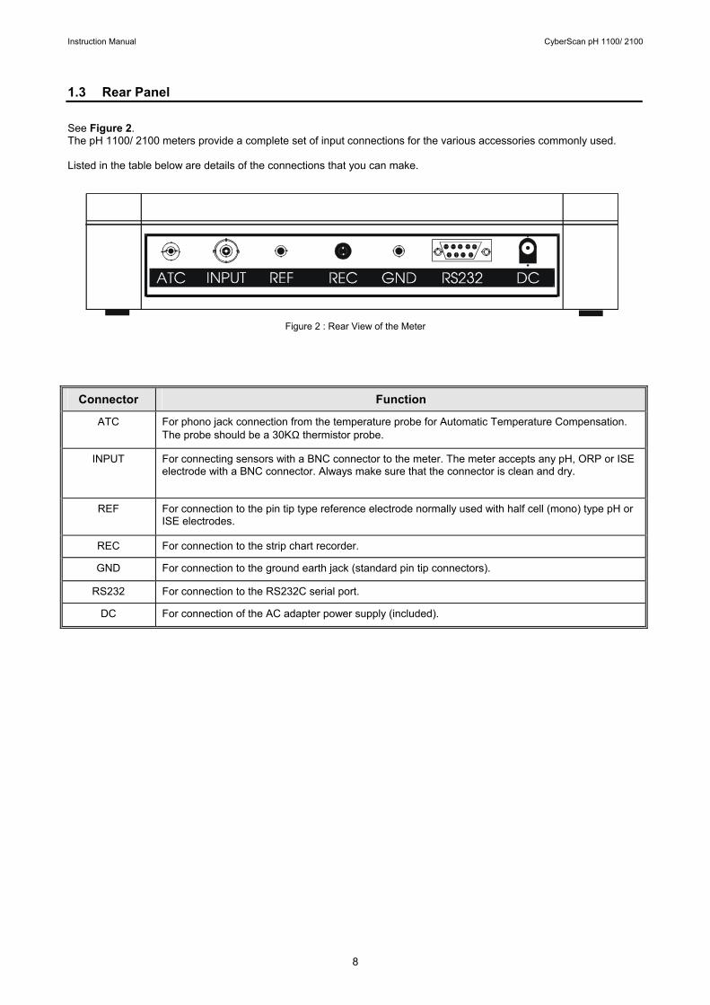
1.3 Rear Panel See Figure 2. The pH 1100/ 2100 meters provide a complete set of input connections for the various accessories commonly used. Listed in the table below are details of the connections that you can make.
Figure 2 : Rear View of the Meter
Connector Function
ATC For phono jack connection from the temperature probe for Automatic Temperature Compensation. The probe should be a 30KΩ thermistor probe.
INPUT For connecting sensors with a BNC connector to the meter. The meter accepts any pH, ORP or ISE electrode with a BNC connector. Always make sure that the connector is clean and dry.
REF For connection to the pin tip type reference electrode normally used with half cell (mono) type pH or ISE electrodes.
REC For connection to the strip chart recorder.
GND For connection to the ground earth jack (standard pin tip connectors).
RS232 For connection to the RS232C serial port.
DC For connection of the AC adapter power supply (included).
Instruction Manual CyberScan pH 1100/ 2100
9
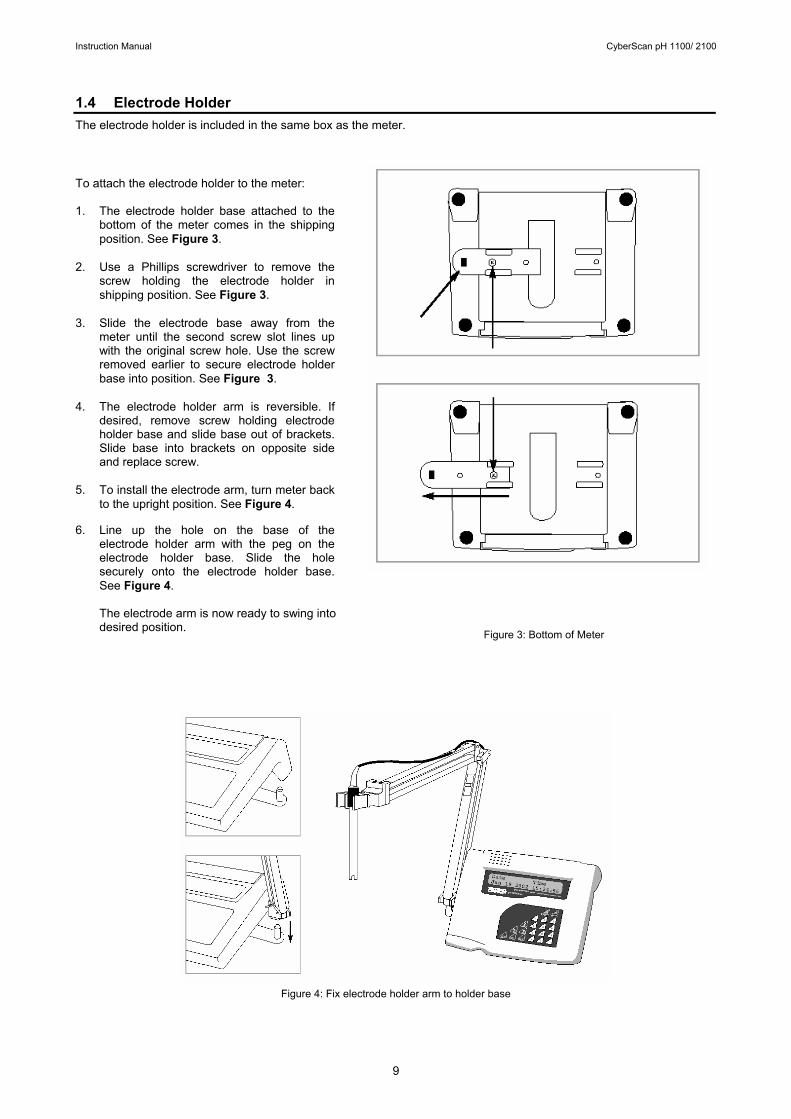
1.4 Electrode Holder The electrode holder is included in the same box as the meter.
To attach the electrode holder to the meter: 1. The electrode holder base attached to the
bottom of the meter comes in the shipping position. See Figure 3.
2. Use a Phillips screwdriver to remove the screw holding the electrode holder in shipping position. See Figure 3.
3. Slide the electrode base away from the meter until the second screw slot lines up with the original screw hole. Use the screw removed earlier to secure electrode holder base into position. See Figure 3.
4. The electrode holder arm is reversible. If desired, remove screw holding electrode holder base and slide base out of brackets. Slide base into brackets on opposite side and replace screw.
5. To install the electrode arm, turn meter back to the upright position. See Figure 4.
6. Line up the hole on the base of the
electrode holder arm with the peg on the electrode holder base. Slide the hole securely onto the electrode holder base. See Figure 4.
The electrode arm is now ready to swing into desired position.
Figure 4: Fix electrode holder arm to holder base
Figure 3: Bottom of Meter

Instruction Manual CyberScan pH 1100/ 2100
10
2 STARTING UP
Attention: Do not get water on the BNC connector during operation. Avoid touching the connector with soiled or wet hands. 2.1 Back Panel Connections Refer back to Figure 2. Make the necessary connections as mentioned in Section 1.3 Rear Panel, pg 8. 2.2 Powering up and powering down 2.2.1 Powering up
1. When first connected to the power supply, the meter runs a
self test, the display flashes Hardware Testing... Status: Pass. See Figure 5.
2. It then displays current date and time. See Figure 6. This display will also appear when the meter is turned off while still connected to the power supply. See Figure 6.
3. See Figure 7. To turn the meter on press ON/OFF. The upper display flashes Bench pH/Ion 2100 for the pH 2100, (Display flashes Bench pH 1100 for the pH 1100 meter.) and then the lower display flashes SW Rev 1.20. See Figure 7.
4. The display flashes System Initializing, Please wait...
See Figure 8.
5. If this is the first power up since the power was connected, you must indicate desired measurement mode. Use >/CAL to select. The mode selected will flash. See Figure 9. Press ENTER to confirm. The meter then enters measurement mode.
6. After initial startup, the meter will automatically return to
the measurement mode previously selected as long as power connection is maintained.
2.2.2 Powering down 1. To turn the meter off press ON/OFF. The display flashes
System Shutting Down, Please wait... See Figure 10. Then, the date and time display will appear. See Figure 6. The date and time will continue to display until the power supply is disconnected.
Hardware Testing. . . .Status: Pass
Date TimeJan 25 2002 09:09:30
System InitializingPlease wait. . .
pH/Temp mV IonSelect & Press ENTER
Figure 5
Figure 6
Figure 7
Figure 8
Figure 9
Figure 10
Bench pH/Ion 2100SW Rev 1.20
System Shutting DownPlease wait. . .

Instruction Manual CyberScan pH 1100/ 2100
11
3 PH CALIBRATION & MEASUREMENT 3.1 pH calibration This meter is capable of up to 5 point calibration with selectable buffer sets (USA, NIST, Bf1, Bf2 or any 5 custom buffers of your choice). The meter retains stored pH calibrations even when turned off. For best accuracy, we recommend that you perform at least a 2-point calibration using buffers that bracket (one above and one below) the expected sample range. You can perform a 1-point calibration, but make sure that the buffer value is close to the sample value you are measuring. For custom buffer sets, you must perform at least a 2 point calibration. Selectable buffer sets: USA: 1.68, 4.01, 7.00, 10.01, 12.45 NIST: 1.68, 4.01, 6.86, 9.18, 12.45 Bf1: 1.68, 4.01, 6.86, 10.01, 12.45 Bf2: 1.68, 4.01, 7.00, 9.18, 12.45 Any 5 user selected custom buffers To select which buffer sets you wish to use see Section 10.2.2: Program pH Buffer Setup: P1.0 in the pH/Temp setup mode (page 30). When you recalibrate your meter, old pH calibration points are replaced on a point by point basis. For example, if you previously calibrated your meter at pH 4.01, 7.00, and 10.01, and you recalibrate at pH 7.00, the meter retains the old calibration data at pH 4.01 and pH 10.01. To view current calibration points, see Section 10.2.8: Program pH Cal Data P1.6 in the pH/Temp setup mode (page 35). If you choose to recalibrate to only 1 or 2 pH values, the older calibration values you do not calibrate to will remain stored. These old stored calibration values may cause accuracy loss when your readings are close to the old values. To clear old calibration data, reset the meter as shown in Section 10.2.9 Program pH Cal Reset: P1.7 in the pH/Temp setup mode (page 36). 3.1.1 Automatic Temperature Compensation (ATC) If you will be taking pH measurement using Automatic Temperature Compensation (ATC), you must perform your pH calibration with ATC temperature probe attached. Attach the temperature probe to the rear of the meter. The ATC mode annunciator shows on the display. See Figure 11. Insert the probe into the pH buffer solution along with your pH electrode. If manual temperature compensation is preferred, do not plug a temperature probe into the meter. The MTC mode annunciator shows on the display. See Figure 12. The default manual temperature compensation is 25.0°C. To change the manual temperature compensation default, see Section 9 Temperature Calibration for instructions (page 26).
7.179pH 25.3 C ATCJan 18 2002 08:46:25
°
7.179pH 25.3 C MTCJan 18 2002 08:46:25
°
Figure 11
Figure 12
Instruction Manual CyberScan pH 1100/ 2100
12
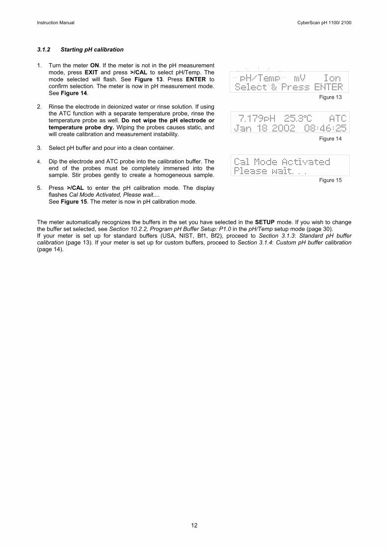
3.1.2 Starting pH calibration 1. Turn the meter ON. If the meter is not in the pH measurement
mode, press EXIT and press >/CAL to select pH/Temp. The mode selected will flash. See Figure 13. Press ENTER to confirm selection. The meter is now in pH measurement mode. See Figure 14.
2. Rinse the electrode in deionized water or rinse solution. If using the ATC function with a separate temperature probe, rinse the temperature probe as well. Do not wipe the pH electrode or temperature probe dry. Wiping the probes causes static, and will create calibration and measurement instability.
3. Select pH buffer and pour into a clean container.
4. Dip the electrode and ATC probe into the calibration buffer. The end of the probes must be completely immersed into the sample. Stir probes gently to create a homogeneous sample.
5. Press >/CAL to enter the pH calibration mode. The display flashes Cal Mode Activated, Please wait.... See Figure 15. The meter is now in pH calibration mode.
The meter automatically recognizes the buffers in the set you have selected in the SETUP mode. If you wish to change the buffer set selected, see Section 10.2.2, Program pH Buffer Setup: P1.0 in the pH/Temp setup mode (page 30). If your meter is set up for standard buffers (USA, NIST, Bf1, Bf2), proceed to Section 3.1.3: Standard pH buffer calibration (page 13). If your meter is set up for custom buffers, proceed to Section 3.1.4: Custom pH buffer calibration (page 14).
Figure 13
Figure 14
Figure 15
pH/Temp mV IonSelect & Press ENTER
7.179pH 25.3 C ATCJan 18 2002 08:46:25
°
Cal Mode ActivatedPlease wait. . .
Instruction Manual CyberScan pH 1100/ 2100
13
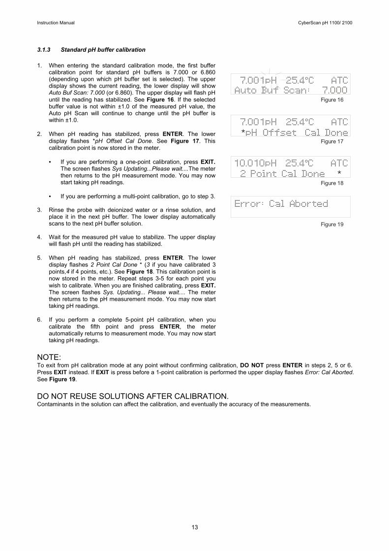
3.1.3 Standard pH buffer calibration 1. When entering the standard calibration mode, the first buffer
calibration point for standard pH buffers is 7.000 or 6.860 (depending upon which pH buffer set is selected). The upper display shows the current reading, the lower display will show Auto Buf Scan: 7.000 (or 6.860). The upper display will flash pH until the reading has stabilized. See Figure 16. If the selected buffer value is not within ±1.0 of the measured pH value, the Auto pH Scan will continue to change until the pH buffer is within ±1.0.
2. When pH reading has stabilized, press ENTER. The lower display flashes *pH Offset Cal Done. See Figure 17. This calibration point is now stored in the meter. • If you are performing a one-point calibration, press EXIT.
The screen flashes Sys Updating...Please wait....The meter then returns to the pH measurement mode. You may now start taking pH readings.
• If you are performing a multi-point calibration, go to step 3.
3. Rinse the probe with deionized water or a rinse solution, and
place it in the next pH buffer. The lower display automatically scans to the next pH buffer solution.
4. Wait for the measured pH value to stabilize. The upper display
will flash pH until the reading has stabilized. 5. When pH reading has stabilized, press ENTER. The lower
display flashes 2 Point Cal Done * (3 if you have calibrated 3 points,4 if 4 points, etc.). See Figure 18. This calibration point is now stored in the meter. Repeat steps 3-5 for each point you wish to calibrate. When you are finished calibrating, press EXIT. The screen flashes Sys. Updating... Please wait.... The meter then returns to the pH measurement mode. You may now start taking pH readings.
6. If you perform a complete 5-point pH calibration, when you
calibrate the fifth point and press ENTER, the meter automatically returns to measurement mode. You may now start taking pH readings.
NOTE: To exit from pH calibration mode at any point without confirming calibration, DO NOT press ENTER in steps 2, 5 or 6. Press EXIT instead. If EXIT is press before a 1-point calibration is performed the upper display flashes Error: Cal Aborted. See Figure 19. DO NOT REUSE SOLUTIONS AFTER CALIBRATION. Contaminants in the solution can affect the calibration, and eventually the accuracy of the measurements.
Figure 16
Figure 17
Figure 18
Figure 19
7.001pH 25.4 C ATCAuto Buf Scan: 7.000
°
7.001pH 25.4 C ATC pH Offset Cal Done
°*
Error: Cal Aborted
10.0102 Point Cal Done *
pH 25.4 C ATC
°

Instruction Manual CyberScan pH 1100/ 2100
14
3.1.4 Custom pH buffer calibration 1. When entering the custom calibration mode, the lower display
will show Key In Std:. The upper display shows the pH buffer the electrode is dipped into. The lower display will show the same value as the upper display only if the meter has not been calibrated or if the meter has been reset. See Figure 20. If the meter has previously been calibrated, the lower display will toggle to the stored calibration point that is closest to current buffer value.
2. Using the numeric keypad (See Figure 21), enter the value of the first custom pH buffer. If you make a mistake, use the ∆/MI or ∇ /MR to highlight mistake, then retype.
3. Press ENTER when first custom pH buffer is keyed in. The display will read 1 Point Cal Done *. See Figure 22. NOTE: In the custom pH buffer calibration mode you must perform at least a 2-point calibration, if you press EXIT before you calibrate at 2 points the screen will flash Error: Cal Aborted (See Figure 23) and will return to the pH measurement mode without confirming any calibration points.
4. Rinse the probe with deionized water or a rinse solution, and place it in the next custom pH buffer. The lower display will show Key In Std: The upper and lower displays show the pH buffer value.
5. Enter the value of the next custom pH buffer. Press ENTER when done. The display will read 2 Point Cal Done *. If you are performing a 2-point calibration, press EXIT. The screen flashes Sys Updating...Please wait... The meter then returns to the pH measurement mode. You may now start taking pH readings. • If you are performing a 3, 4 or 5-point calibration go to step
6.
6. Repeat steps 4 and 5 for each additional custom buffer. Upon confirmation of pH buffer, the display will read 3 Point Cal Done * (4 if you have calibrated points, etc). When you have finished calibrating desired number of points, press EXIT. The screen flashes Sys. Updating... Please wait... The meter then returns to the pH measurement mode. If you have entered 5 calibration points, the meter will automatically return to pH measurement mode. You may start taking pH readings.
NOTE: To exit from pH calibration mode at any point without confirming calibration, DO NOT press ENTER in steps 3 or 5. Press EXIT. If EXIT is pressed before a 2-point calibration is performed the upper display flashes Error: Cal Aborted. See Figure 23. DO NOT REUSE SOLUTIONS AFTER CALIBRATION. Contaminants in the solution can affect the calibration, and eventually the accuracy of the measurements.
Figure 20
Figure 21
Figure 22
Figure 23
7.179pH 25.3 C ATCKey In Std: 7.179
°
Error: Cal Aborted
7.179pH 25.3 C ATC1
°
Point Cal Done *
Numeric Keypad
7.179pH 25.3 C ATCKey In Std: 7.179
°
7.179pH 25.3 C ATC1 Cal Point Done
°*
Instruction Manual CyberScan pH 1100/ 2100
15
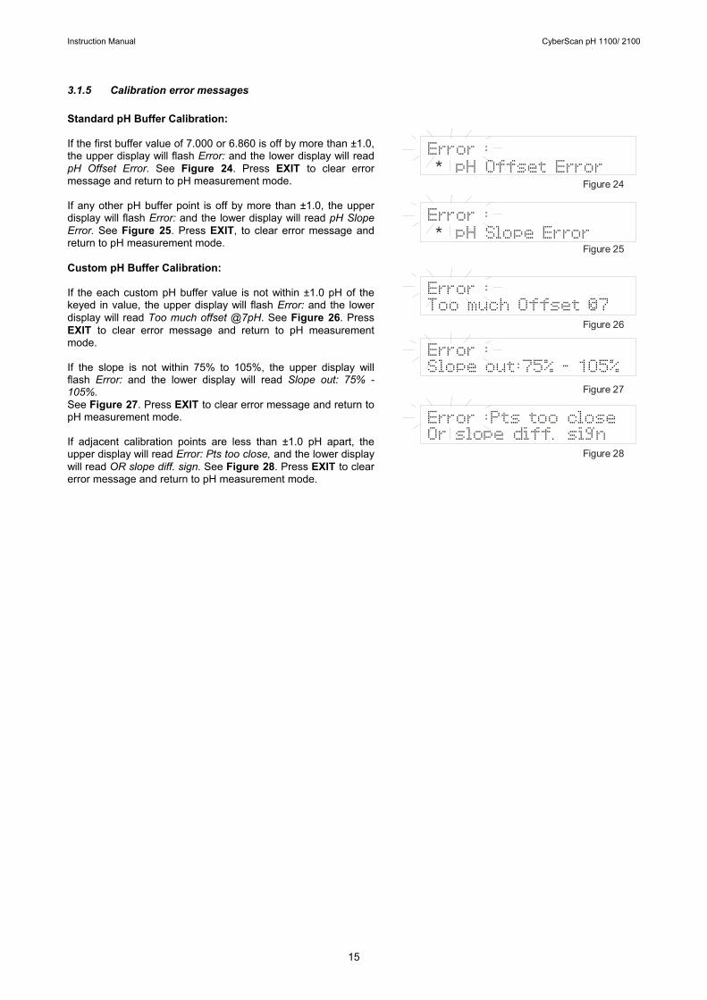
3.1.5 Calibration error messages Standard pH Buffer Calibration: If the first buffer value of 7.000 or 6.860 is off by more than ±1.0, the upper display will flash Error: and the lower display will read pH Offset Error. See Figure 24. Press EXIT to clear error message and return to pH measurement mode. If any other pH buffer point is off by more than ±1.0, the upper display will flash Error: and the lower display will read pH Slope Error. See Figure 25. Press EXIT, to clear error message and return to pH measurement mode. Custom pH Buffer Calibration: If the each custom pH buffer value is not within ±1.0 pH of the keyed in value, the upper display will flash Error: and the lower display will read Too much offset @7pH. See Figure 26. Press EXIT to clear error message and return to pH measurement mode. If the slope is not within 75% to 105%, the upper display will flash Error: and the lower display will read Slope out: 75% - 105%. See Figure 27. Press EXIT to clear error message and return to pH measurement mode. If adjacent calibration points are less than ±1.0 pH apart, the upper display will read Error: Pts too close, and the lower display will read OR slope diff. sign. See Figure 28. Press EXIT to clear error message and return to pH measurement mode. /measurement
Figure 24
Figure 25
Figure 26
Figure 27
Figure 28
Error : pH Offset Error*
Error : pH Slope Error*
Error :Too much Offset @7
Error :Slope out:75% - 105%
Error :Pts too closeOr slope diff. sign
Instruction Manual CyberScan pH 1100/ 2100
16
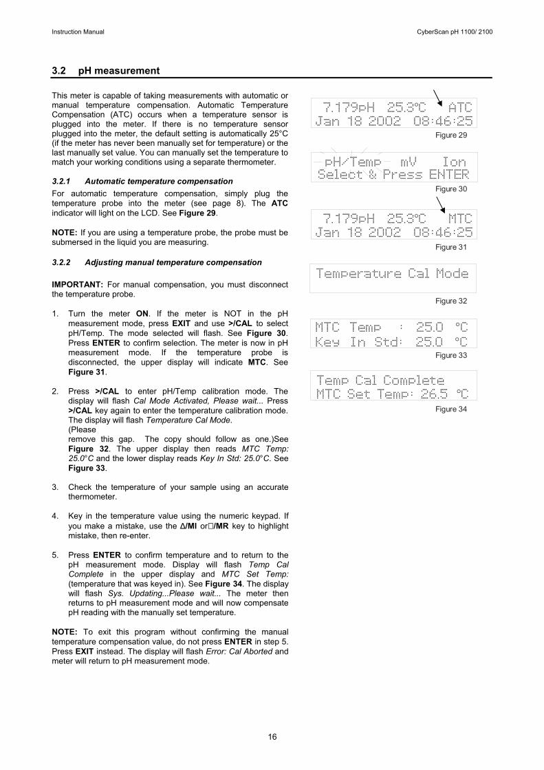
3.2 pH measurement This meter is capable of taking measurements with automatic or manual temperature compensation. Automatic Temperature Compensation (ATC) occurs when a temperature sensor is plugged into the meter. If there is no temperature sensor plugged into the meter, the default setting is automatically 25°C (if the meter has never been manually set for temperature) or the last manually set value. You can manually set the temperature to match your working conditions using a separate thermometer. 3.2.1 Automatic temperature compensation For automatic temperature compensation, simply plug the temperature probe into the meter (see page 8). The ATC indicator will light on the LCD. See Figure 29. NOTE: If you are using a temperature probe, the probe must be submersed in the liquid you are measuring. 3.2.2 Adjusting manual temperature compensation
IMPORTANT: For manual compensation, you must disconnect the temperature probe. 1. Turn the meter ON. If the meter is NOT in the pH
measurement mode, press EXIT and use >/CAL to select pH/Temp. The mode selected will flash. See Figure 30. Press ENTER to confirm selection. The meter is now in pH measurement mode. If the temperature probe is disconnected, the upper display will indicate MTC. See Figure 31.
2. Press >/CAL to enter pH/Temp calibration mode. The display will flash Cal Mode Activated, Please wait... Press >/CAL key again to enter the temperature calibration mode. The display will flash Temperature Cal Mode. (Please remove this gap. The copy should follow as one.)See Figure 32. The upper display then reads MTC Temp: 25.0°C and the lower display reads Key In Std: 25.0°C. See Figure 33.
3. Check the temperature of your sample using an accurate thermometer.
4. Key in the temperature value using the numeric keypad. If you make a mistake, use the ∆/MI or∇ /MR key to highlight mistake, then re-enter.
5. Press ENTER to confirm temperature and to return to the pH measurement mode. Display will flash Temp Cal Complete in the upper display and MTC Set Temp: (temperature that was keyed in). See Figure 34. The display will flash Sys. Updating...Please wait... The meter then returns to pH measurement mode and will now compensate pH reading with the manually set temperature.
NOTE: To exit this program without confirming the manual temperature compensation value, do not press ENTER in step 5. Press EXIT instead. The display will flash Error: Cal Aborted and meter will return to pH measurement mode.
pH/Temp mV IonSelect & Press ENTER
7.179pH 25.3 C ATCJan 18 2002 08:46:25
°
Figure 29
Figure 30
Figure 31
Figure 32
Figure 33
Figure 34
Temperature Cal Mode
MTC Temp : 25.0 CKey In Std: 25.0 C
°°
7.179pH 25.3 C MTCJan 18 2002 08:46:25
°
Temp Cal CompleteMTC Set Temp: 26.5 C °
Instruction Manual CyberScan pH 1100/ 2100
17
3.2.3 Taking pH Measurements NOTE: Be sure to remove the electrode soaker bottle or protective rubber cap on the electrode before measurement. 1. Rinse the probe with deionized or distilled water before use
to remove any impurities adhering to the probe body. If the pH electrode dehydrated, soak it for 30 minutes in electrode storage solution or a 2M to 4M KCl solution.
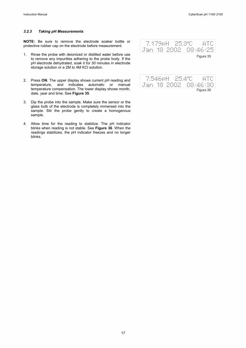
2. Press ON. The upper display shows current pH reading and temperature, and indicates automatic or manual temperature compensation. The lower display shows month, date, year and time. See Figure 35.
3. Dip the probe into the sample. Make sure the sensor or the glass bulb of the electrode is completely immersed into the sample. Stir the probe gently to create a homogenous sample.
4. Allow time for the reading to stabilize. The pH indicator blinks when reading is not stable. See Figure 36. When the readings stabilizes, the pH indicator freezes and no longer blinks.
7.179pH 25.3 C ATCJan 18 2002 08:46:25
°
Figure 35
Figure 36
7.546pH 25.4 C ATCJan 18 2002 08:46:30
°
Instruction Manual CyberScan pH 1100/ 2100
18
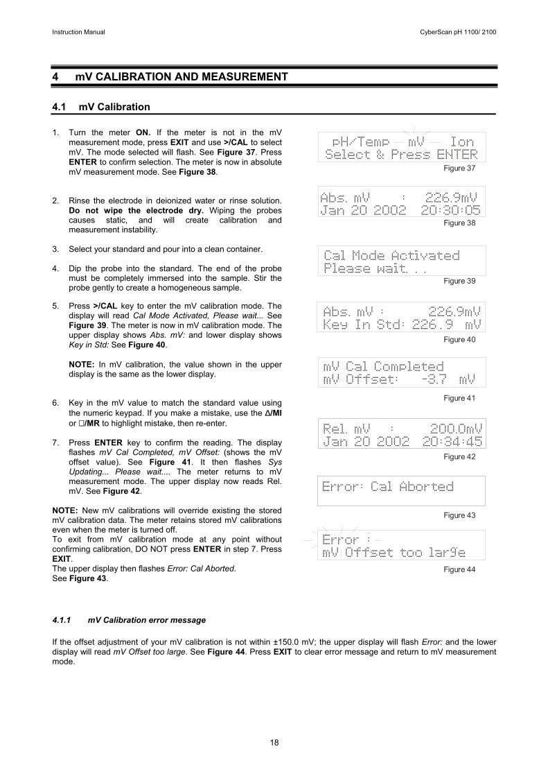
4 mV CALIBRATION AND MEASUREMENT 4.1 mV Calibration 1. Turn the meter ON. If the meter is not in the mV
measurement mode, press EXIT and use >/CAL to select mV. The mode selected will flash. See Figure 37. Press ENTER to confirm selection. The meter is now in absolute mV measurement mode. See Figure 38.
2. Rinse the electrode in deionized water or rinse solution. Do not wipe the electrode dry. Wiping the probes causes static, and will create calibration and measurement instability.
3. Select your standard and pour into a clean container.
4. Dip the probe into the standard. The end of the probe must be completely immersed into the sample. Stir the probe gently to create a homogeneous sample.
5. Press >/CAL key to enter the mV calibration mode. The
display will read Cal Mode Activated, Please wait... See Figure 39. The meter is now in mV calibration mode. The upper display shows Abs. mV: and lower display shows Key in Std: See Figure 40. NOTE: In mV calibration, the value shown in the upper display is the same as the lower display.
6. Key in the mV value to match the standard value using
the numeric keypad. If you make a mistake, use the ∆/MI or ∇ /MR to highlight mistake, then re-enter.
7. Press ENTER key to confirm the reading. The display flashes mV Cal Completed, mV Offset: (shows the mV offset value). See Figure 41. It then flashes Sys Updating... Please wait.... The meter returns to mV measurement mode. The upper display now reads Rel. mV. See Figure 42.
NOTE: New mV calibrations will override existing the stored mV calibration data. The meter retains stored mV calibrations even when the meter is turned off. To exit from mV calibration mode at any point without confirming calibration, DO NOT press ENTER in step 7. Press EXIT. The upper display then flashes Error: Cal Aborted. See Figure 43. 4.1.1 mV Calibration error message If the offset adjustment of your mV calibration is not within ±150.0 mV; the upper display will flash Error: and the lower display will read mV Offset too large. See Figure 44. Press EXIT to clear error message and return to mV measurement mode.
pH/Temp mV IonSelect & Press ENTER
Rel. mV : 200.0mVJan 20 2002 20:34:45
Abs. mV : 226.9mVJan 20 2002 20:30:05
Figure 37
Figure 38
Figure 39
Figure 40
Figure 41
Figure 42
Figure 43
Figure 44
Cal Mode ActivatedPlease wait. . .
Error: Cal Aborted
Abs. mV : 226.9mVKey In Std: 226 . 9 mV
mV Cal CompletedmV Offset: -3.7 mV
Error :mV Offset too large
Instruction Manual CyberScan pH 1100/ 2100
19
4.2 mV Measurement 1. Turn the meter ON. If the meter is NOT in the mV
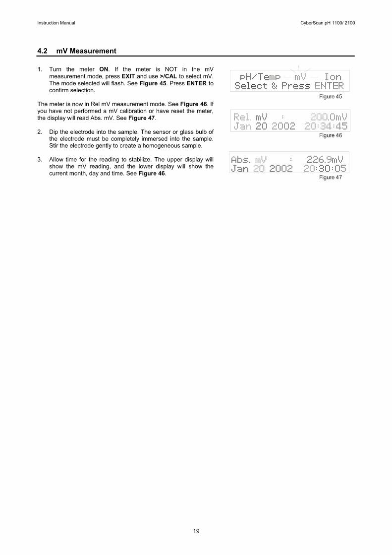
measurement mode, press EXIT and use >/CAL to select mV. The mode selected will flash. See Figure 45. Press ENTER to confirm selection.
The meter is now in Rel mV measurement mode. See Figure 46. If you have not performed a mV calibration or have reset the meter, the display will read Abs. mV. See Figure 47.
2. Dip the electrode into the sample. The sensor or glass bulb of
the electrode must be completely immersed into the sample. Stir the electrode gently to create a homogeneous sample.
3. Allow time for the reading to stabilize. The upper display will show the mV reading, and the lower display will show the current month, day and time. See Figure 46.
pH/Temp mV IonSelect & Press ENTER
Rel. mV : 200.0mVJan 20 2002 20:34:45
Abs. mV : 226.9mVJan 20 2002 20:30:05
Figure 45
Figure 46
Figure 47

Instruction Manual CyberScan pH 1100/ 2100
20
5 ION CALIBRATION AND MEASUREMENT (ONLY APPLICABLE FOR pH 2100) The pH 2100 meter reads ion concentration in ppm, ppt, mg/l, g/l, mmol/l and mol/l units. See Ion setup Program P3.0 (page 43) to select ion concentration units. 5.1 Ion calibration This instrument is capable of up to 5-point custom ion calibration with a minimum of 2-point calibration. Custom calibration values can be any value between 0.001 and 19998. Once the first calibration value is keyed in, all other calibration will automatically be at least one decade apart. For example if your first calibration point is at 0.001, all other calibration points will be at least one decade apart from 0.001 (0.001, 0.01, 0.1,1.0, 10.0, 100, 1000, 10000). For best accuracy calibrate your meter to points with similar concentrations to the solutions you want to test. 1. Connect an Ion Selective Electrode (ISE) to the BNC input
connector on the back of the meter. 2. Turn the meter ON. If the meter is not in the Ion measurement
mode, press EXIT and use >/CAL to select Ion. The mode selected will flash. See Figure 48. Press ENTER to confirm selection. The meter is now in Ion measurement mode.
3. If the meter has not been calibrated or has been reset, the
display will flash Ion Meas and current mV value. See Figure 49. If the meter has been calibrated previously, the display will show the current concentration value plus the absolute mV produced by the electrode.
4. Dip the electrode into the first calibration standard. Start with
the calibration standard that has the lowest concentration and move up to higher concentration standards.
5. Press >/CAL to enter the ion calibration mode. The display will
flash Cal Mode Activated, Please wait... See Figure 50. The display then shows Ion Conc: ppm (or unit selected in ion setup mode) in the upper display and Abs. mV: in the lower display. See Figure 51.
6. The first calibration point must be keyed in by the user. Key in
the concentration value of the standard using the numeric keypad. If you make a mistake, use the ∆/MI or ∇ /MR keys to highlight mistake, then re-enter.
7. Press ENTER to confirm the first calibration point. The display
will flash 1 Cal Point Done *, then the meter proceeds to the next calibration point at least 1 decade apart from the first calibration point. See Figure 52.
8. Use ∆/MI or ∇ /MR keys to move the cursor to next calibration
point. All points will be a decade apart from the first calibration point.
9. Rinse off the electrode with deionized water before placing it
in the next calibration standard. 10. Allow probe to stabilize in calibration standard. Press ENTER
to confirm. The display flashes 2 Point Cal Done *. See Figure 53. The meter proceeds to the next calibration point.
pH/Temp mV IonSelect & Press ENTER
Cal Mode ActivatedPlease wait. . .
Ion Meas 160.3mVJan 20 2002 21:54:34
Figure 48
Figure 49
Figure 50
Figure 51
Figure 52
Figure 53
Ion Conc: ppmAbs. mV : 100.7mV
Ion Conc: ppmAbs. mV : 100.7mV
Ion Conc:0.01ppm1 Point Cal Done *
Ion Conc:0.10ppm2 Point Cal Done *

Instruction Manual CyberScan pH 1100/ 2100
21
If you are performing a 2-point calibration, press EXIT. The screen flashes Aver. Slope = (the average slope of the electrode) in the upper display and Sys Updating... in the lower display. See Figure 54. The meter returns to the Ion measurement mode. You may now start taking readings. If you are performing a 3, 4 or 5-point calibration go to step 11. 11. Use ∆/MI or ∇ /MR keys to move the cursor to next calibration
point. 12. Rinse off the electrode with deionized water before placing it in
the next calibration standard. 13. Allow probe to stabilize in calibration standard. Press ENTER
to confirm. The display flashes 3 Point Cal Done * (4 for 4 point, etc.). See Figure 55. The meter proceeds to the next calibration point.
14. Repeat steps 11-13 until you finish calibrating at desired
number of points (up to 5 points). Press EXIT. The screen flashes Aver.Slope = (the average slope of the electrode) in the upper display and Sys Updating... in the lower display. See Figure 54. The meter returns to the Ion measurement mode. At the end of a 5-point calibration, the meter automatically flashes Aver. Slope = and Sys Updating, and returns to measurement mode.
NOTES: You may compare the average electrode slope value with the expected slope value for your electrode from your electrode manual to verify electrode operation. If you want to leave the calibration mode prior to confirming two calibration points, press EXIT key to exit calibration mode. The meter will revert to back to the earlier calibration curve. If you have calibrated to two points, pressing EXIT will confirm the new calibration. New ion calibrations will over-ride the existing stored ion calibration data. The meter retains stored ion calibrations even when the meter is turned off or if the power cord is unplugged or power is cut off to the AC adapter. 5.2 Ion calibration error messages If you leave the ion calibration mode prior to confirming two calibration points by pressing the EXIT key, the screen will flash Error: Cal Aborted. See Figure 56. The meter will revert to back to the earlier calibration curve and return to the ion measurement mode. If the average ion slope is not within 10 to 75 mV per decade, the upper display will flash Error: and the lower display will read Ion Slope Error. See Figure 57.
Error :Slope ErrorIon
Error: Cal Aborted
Figure 56
Figure 57
Ion Conc: 1.0ppm3 Point Cal Done *
Figure 54
Figure 55
Aver. Slope = 49.2mVSys Updating. . .
Instruction Manual CyberScan pH 1100/ 2100
22
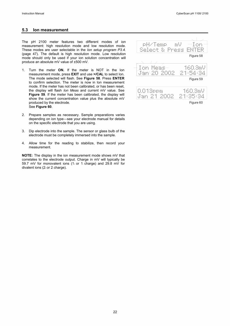
5.3 Ion measurement The pH 2100 meter features two different modes of ion measurement: high resolution mode and low resolution mode. These modes are user selectable in the Ion setup program P3.4. (page 47). The default is high resolution mode. Low resolution mode should only be used if your ion solution concentration will produce an absolute mV value of ±500 mV. 1. Turn the meter ON. If the meter is NOT in the Ion
measurement mode, press EXIT and use >/CAL to select Ion. The mode selected will flash. See Figure 58. Press ENTER to confirm selection. The meter is now in Ion measurement mode. If the meter has not been calibrated, or has been reset, the display will flash Ion Meas and current mV value. See Figure 59. If the meter has been calibrated, the display will show the current concentration value plus the absolute mV produced by the electrode. See Figure 60.
2. Prepare samples as necessary. Sample preparations varies
depending on ion type—see your electrode manual for details on the specific electrode that you are using.
3. Dip electrode into the sample. The sensor or glass bulb of the
electrode must be completely immersed into the sample. 4. Allow time for the reading to stabilize, then record your
measurement. NOTE: The display in the ion measurement mode shows mV that correlates to the electrode output. Charge in mV will typically be 59.7 mV for monovalent ions (1+ or 1- charge) and 29.8 mV for divalent ions (2+ or 2- charge).
pH/Temp mV IonSelect & Press ENTER
Ion Meas 160.3mVJan 20 2002 21:54:34
0.013ppm 160.3mVJan 21 2002 21:35:34
Figure 58
Figure 59
Figure 60
Instruction Manual CyberScan pH 1100/ 2100
23
6 MEMORY FUNCTIONS 6.1 Memory input This meter can store up to 100 sets of data in several combinations:
pH 1100 meter: • pH, temperature, date and time • mV, temperature, date and time pH 2100 meter: • pH, temperature, date and time • mV, temperature, date and time • ion, mV, date and time
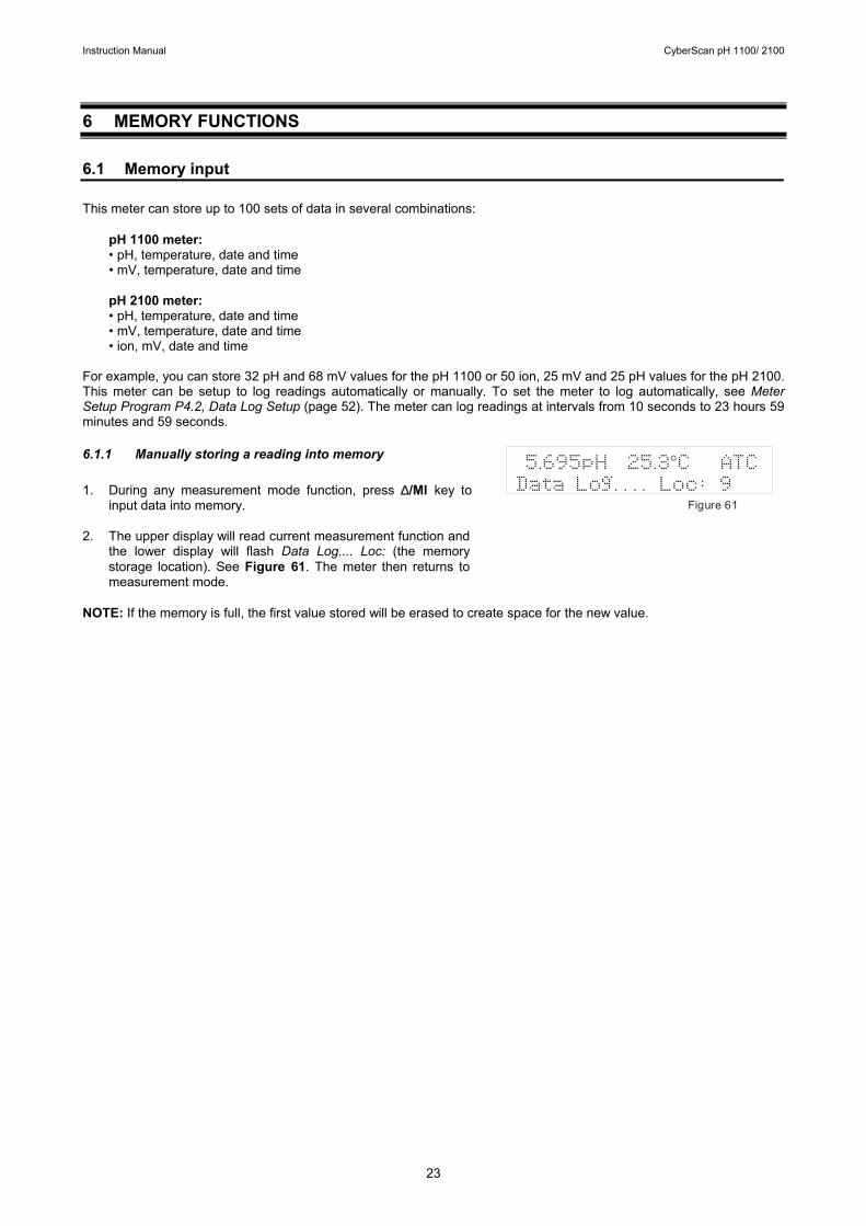
For example, you can store 32 pH and 68 mV values for the pH 1100 or 50 ion, 25 mV and 25 pH values for the pH 2100. This meter can be setup to log readings automatically or manually. To set the meter to log automatically, see Meter Setup Program P4.2, Data Log Setup (page 52). The meter can log readings at intervals from 10 seconds to 23 hours 59 minutes and 59 seconds. 6.1.1 Manually storing a reading into memory 1. During any measurement mode function, press ∆/MI key to
input data into memory. 2. The upper display will read current measurement function and
the lower display will flash Data Log.... Loc: (the memory storage location). See Figure 61. The meter then returns to measurement mode.
NOTE: If the memory is full, the first value stored will be erased to create space for the new value.
Figure 61
5.695pH 25.3 C ATCData Log. . . . Loc: 9
°

Instruction Manual CyberScan pH 1100/ 2100
24
6.2 Memory recall This function recalls the previous readings stored in the memory. You can only access memory recall from the measurement mode. Memory recall is in “Last In First Out” (LIFO) order. There are two methods of viewing stored data in the memory recall function: manual and automatic. In manual memory recall, the user must manually scroll through the memory points using the ∆/MI and ∇ /MR keys. In automatic memory recall, the meter automatically scrolls through the memory points. To choose the method of viewing stored data you wish to use, see Meter Setup mode Program P4.3 MemRecall Setup (page 52). 6.2.1 Recalling readings in manual recall mode 1. Press the ∇ /MR key once to retrieve the last reading stored.
The display flashes Mem Recall Activated, Please wait... See Figure 62.
The display then flashes the memory location last stored in the lower display. See Figure 63. Then the display shows the recorded value (pH/temp, mV or Ion/mV) in the upper display and toggles between memory location and date in the lower display. See Figures 64-65.
2. Use the ∇ /MR key to select the next memory location or the
∆/MI key to select the previous memory location. 3. Repeat step 2 to review additional stored data sets. 4. To exit Memory Recall, press EXIT and return to the
measurement mode. 6.2.2 Recalling readings in automatic recall mode 1. Press the ∇ /MR key once to retrieve the last reading stored.
The display flashes Mem Recall Activated, Please wait... See Figure 62. The display then flashes the memory location last stored in the lower display. See Figure 63. Then the display shows the recorded value (pH/temp, mV or Ion/mV) in the upper display and date and time in the lower display. See Figure 64.
2. After 8 seconds, the meter automatically scrolls to the next to
memory location. The display flashes the next memory location stored. See Figure 66. The display then shows the recorded value (pH/temp, mV or Ion/mV) in the upper display and date and time in the lower display. See Figure 67.
3. The meter will continuously scroll through all the memory points
stored indefinitely. To exit memory recall, press EXIT and return to the measurement mode.
NOTES: If no new readings are stored after memory recall function has been exited, the next time the memory recall function is activated, it will resume at the memory location point where it was last exited. If a new point is stored, the memory recall function will begin with that point. Readings stored in memory are retained even if the unit is turned off. To erase all readings stored in memory, see Meter Setup Program P4.6, Mem Clear Setup (page 54).
7.545pH 25.4 C ATCJan 18 2002 08:50:35
°
5.695pH 25.3 C ATCJan 21 2002 08:52:35
°
Figure 62
Figure 63
Figure 64
Figure 65
Figure 66
Figure 67
Mem Recall ActivatedPlease wait. . .
Mem Loc:9
Mem Loc:8
5.695pH 25.3 C ATCMem Loc:9 08:52:35
°
Instruction Manual CyberScan pH 1100/ 2100
25
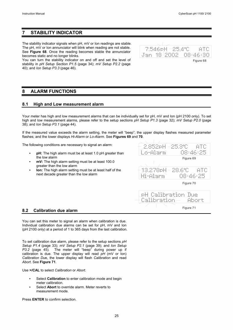
7 STABILITY INDICATOR The stability indicator signals when pH, mV or Ion readings are stable. The pH, mV or Ion annunciator will blink when reading are not stable. See Figure 68. Once the reading becomes stable the annunciator becomes static and no longer blinks. You can turn the stability indicator on and off and set the level of stability in pH Setup Section P1.5 (page 34); mV Setup P2.2 (page 40); and Ion Setup P3.3 (page 46).
8 ALARM FUNCTIONS 8.1 High and Low measurement alarm Your meter has high and low measurement alarms that can be individually set for pH, mV and Ion (pH 2100 only). To set high and low measurement alarms, please refer to the setup sections pH Setup P1.3 (page 32); mV Setup P2.0 (page 38); and Ion Setup P3.1 (page 44). If the measured value exceeds the alarm setting, the meter will “beep”; the upper display flashes measured parameter flashes; and the lower displays Hi-Alarm or Lo-Alarm. See Figures 69 and 70. The following conditions are necessary to signal an alarm:
• pH: The high alarm must be at least 1.0 pH greater than
the low alarm • mV: The high alarm setting must be at least 100.0
greater than the low alarm • Ion: The high alarm setting must be at least half of the
next decade greater than the low alarm 8.2 Calibration due alarm You can set this meter to signal an alarm when calibration is due. Individual calibration due alarms can be set for pH, mV and Ion (pH 2100 only) at a period of 1 to 365 days from the last calibration. To set calibration due alarm, please refer to the setup sections pH Setup P1.4 (page 33); mV Setup P2.1 (page 39); and Ion Setup P3.2 (page 45). The meter will “beep” during power up if calibration is due. The upper display will read pH (mV or Ion) Calibration Due, the lower display will flash Calibration and read Abort. See Figure 71. Use >/CAL to select Calibration or Abort.
• Select Calibration to enter calibration mode and begin
meter calibration. • Select Abort to override alarm. Meter reverts to
measurement mode. Press ENTER to confirm selection.
7.546pH 25.4 C ATCJan 18 2002 08:46:30
°
Figure 68
2.852pH 25.3 C ATCLo-Alarm 08:46:25
°
pH Calibration DueCalibration Abort
13.278pH 28.6 C ATCHi-Alarm 08:46:25
°
Figure 69
Figure 70
Figure 71

Instruction Manual CyberScan pH 1100/ 2100
26
9 TEMPERATURE CALIBRATION 9.1 Temperature Calibration For this calibration procedure, the ATC probe should be attached to the meter. ATC will appear in the upper display. See Figure 72. 1. Dip the temperature probe into a solution of known temperature,
such as a temperature bath, for a few minutes until the temperature probe stabilizes.
2. If you are not already in pH/temp measurement mode, press
EXIT and use >/CAL to select pH/Temp. The mode selected will flash See Figure 73. Press ENTER to confirm selection. The meter is now in pH measurement mode.
3. Press >/CAL to enter pH/Temp calibration mode. The display
will flash Cal Mode Activated, Please wait... Press >/CAL again to enter the temperature calibration mode. The display will flash Temperature Cal Mode. See Figure 74. Then the upper display will read ATC Temp: (current temperature) and the lower display will read Key In Std: (current temperature). See Figure 75.
4. Key in the known temperature value from step 1 using the
numeric keypad. If you make a mistake, use the ∆/MI or ∇ /MR keys to highlight mistake, then re-enter.
5. Press ENTER to confirm. The display flashes Temp Cal
Complete, ATC Offset: (shows offset value). See Figure 76. The display then flashes Sys Updating, Please wait..., and the meter returns to pH measurement mode.
NOTE: The meter will not allow input values that exceed the allowable limit of ±5°C (±9°F) of the original displayed reading. 9.2 Temperature Calibration Error Messages
If you press EXIT to leave the temperature calibration mode prior to confirming the calibration, the screen will flash Error: Cal Aborted. See Figure 77. The meter then returns to pH measurement mode. If the temperature value keyed in (temperature offset) is not within ±5.0°C (±9.0°F) of the current temperature value, the upper display will flash Error: and the lower display will read ATC offset too large. See Figure 78. The meter returns to temperature calibration mode and a new temperature offset value needs to be entered.
Error :ATC Offset too large
ATC Temp : 25.0 CKey In Std: 25.0 C
°°
Temperature Cal Mode
Error: Cal Aborted
pH/Temp mV IonSelect & Press ENTER
7.546pH 25.3 C ATCJan 18 2002 08:46:30
°
Figure 72
Figure 73
Figure 74
Figure 75
Figure 76
Figure 77
Figure 78
Temp Cal CompleteATC Offset: 2.0 C °
Instruction Manual CyberScan pH 1100/ 2100
27
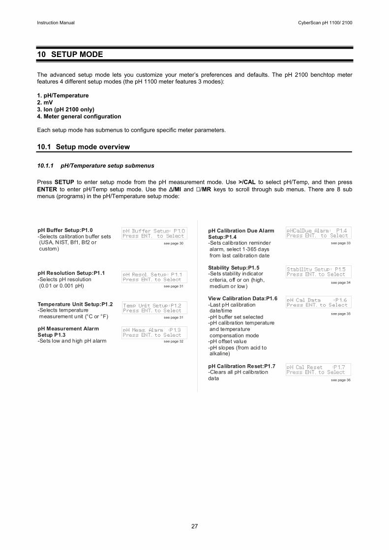
10 SETUP MODE The advanced setup mode lets you customize your meter’s preferences and defaults. The pH 2100 benchtop meter features 4 different setup modes (the pH 1100 meter features 3 modes): 1. pH/Temperature 2. mV 3. Ion (pH 2100 only) 4. Meter general configuration Each setup mode has submenus to configure specific meter parameters. 10.1 Setup mode overview 10.1.1 pH/Temperature setup submenus Press SETUP to enter setup mode from the pH measurement mode. Use >/CAL to select pH/Temp, and then press ENTER to enter pH/Temp setup mode. Use the ∆/MI and ∇ /MR keys to scroll through sub menus. There are 8 sub menus (programs) in the pH/Temperature setup mode:
pHCalDue Alarm: P1.4Press ENT. to Select
Stability Setup: P1.5Press ENT. to Select
pH Cal Data :P1.6Press ENT. to Select
pH Cal Reset :P1.7Press ENT. to Select
pH Buffer Setup:P1.0
pH Resolution Setup:P1.1
Temperature Unit Setup:P1.2
pH Measurement Alarm Setup P1.3
-Selects calibration buffer sets (USA, NIST, Bf1, Bf2 or custom)
-Selects pH resolution (0.01 or 0.001 pH)
-Selects temperature measurement unit (°C or °F)
-Sets low and high pH alarm
pH Calibration Due Alarm Setup:P1.4
Stability Setup:P1.5
View Calibration Data:P1.6
pH Calibration Reset:P1.7
-Sets calibration reminder alarm, select 1-365 days from last calibration date
-Sets stability indicator criteria, off or on (high, medium or low)
-Last pH calibration date/time-pH buffer set selected-pH calibration temperature and temperature compensation mode-pH offset value-pH slopes (from acid to alkaline)
-Clears all pH calibration data
see page 30
see page 31
see page 31
see page 32
see page 33
see page 34
see page 35
see page 36
pH Buffer Setup: P1.0Press ENT. to Select
pH Resol. Setup: P1.1Press ENT. to Select
Temp Unit Setup:P1.2Press ENT. to Select
pH Meas. Alarm :P1.3Press ENT. to Select
Instruction Manual CyberScan pH 1100/ 2100
28
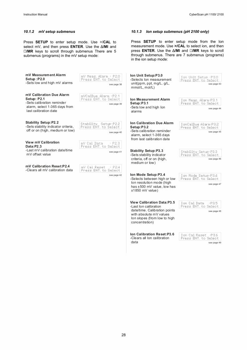
10.1.2 mV setup submenus Press SETUP to enter setup mode. Use >/CAL to select mV, and then press ENTER. Use the ∆/MI and ∇ /MR keys to scroll through submenus There are 5 submenus (programs) in the mV setup mode:
10.1.3 Ion setup submenus (pH 2100 only) Press SETUP to enter setup mode from the Ion measurement mode. Use >/CAL to select ion, and then press ENTER. Use the ∆/MI and ∇ /MR keys to scroll through submenus. There are 7 submenus (programs) in the ion setup mode:
mV Meas. Alarm : P2.0Press ENT. to Select
mVCalDue Alarm :P2.1Press ENT. to Select
Stability Setup:P2.2Press ENT. to Select
mV Cal Data : P2.3Press ENT. to Select
mV Cal Reset : P2.4Press ENT. to Select
mV Measurement AlarmSetup :P2.0
mV Calibration Due AlarmSetup: P2.1
Stability Setup:P2.2
View mV Calibration Data:P2.3
mV Calibration Reset:P2.4
-Sets low and high mV alarms
-Sets calibration reminder alarm, select 1-365 days from last calibration date
-Sets stability indicator criteria, off or on (high, medium or low)
-Last mV calibration date/time mV offset value
-Clears all mV calibration data
Ion Unit Setup:P3.0
Ion Measurement Alarm Setup:P3.1
Ion Calibration Due Alarm Setup:P3.2
Stability Setup:P3.3
Ion Mode Setup:P3.4
View Calibration Data:P3.5
Ion Calibration Reset:P3.6
-Selects Ion measurement unit(ppm, ppt, mg/L, g/L, mmol/L, mol/L)
-Sets low and high Ion alarms
-Sets calibration reminder alarm, select 1-365 days from last calibration date
-Sets stability indicator criteria, off or on (high, medium or low)
-Selects between high or low Ion resolution mode (high has ±500 mV value, low has ±1850 mV value)
-Last Ion calibration date/time. Calibration points with absolute mV values Ion slopes (from low to high concentration)
-Clears all Ion calibration data
see page 38
see page 39
see page 40
see page 41
see page 42
see page 43
see page 44
see page 45
see page 46
see page 47
see page 48
see page 49
Ion Unit Setup :P3.0Press ENT. to Select
IonCalDue Alarm:P3.2Press ENT. to Select
Ion Meas. Alarm:P3.1Press ENT. to Select
Stability Setup:P3.3Press ENT. to Select
Ion Mode Setup:P3.4Press ENT. to Select
Ion Cal Data :P3.5Press ENT. to Select
Ion Cal Reset :P3.6Press ENT. to Select

Instruction Manual CyberScan pH 1100/ 2100
29
10.1.4 Meter general configuration setup submenus
Press SETUP to enter setup mode. Use >/CAL to select meter, and then press ENTER. Use the ∆/MI and ∇ /MR keys to scroll through submenus. There are 8 submenus (programs) in the meter setup mode:
Mem Clear Setup:P4.6Press ENT. to Select
Meter Reset :P4.7 Press ENT. to Select
Date/Time Setup:P4.0Press ENT. to Select
Backlight Setup:P4.1Press ENT. to Select
Data Log Setup:P4.2Press ENT. to Select
Data Transfer :P4.5Press ENT. to Select
Date/Time Setup:P4.0
Backlight Setup:P4.1
Data Log Setup:P4.2
Memory Recall Setup:P4.3
Rs232 Communication Setup:P4.4
Data Transfer Setup:P4.5
Sets day, month, year, hour and minute
-Turns backlight on or off and selects amount of t ime backlight stays on after button press
-Sets automatic or manual memory recall
-Selects automatic or manual memory recall.
-Sets Baud Rate (4800, 9600 or 19200)-Sets Stop Bit (One or Two)-Sets Parity (None, Odd or Even)
-Selects what data gets sent to computer/printer when PRINT
and sets datalogging time interval (10 seconds to 23 hours, 59 minutes, 59 seconds).
Memory Clear Setup:P4.6
Meter Reset:P4.7
Clears data from stored memory
-Resets meter to factory defaults
-Clears all pH/mV/Ion calibration data-Resets manual temperature compensation to 25.0°C-Resets pH/mV/Ion measurement alarm to OFF-Resets pH/mV/Ion calibration due alarm to OFF-Resets stable indicator to ON with low stability setting-Resets datalogging and memory recall to manual-Resets backlight to ON with 2.0 minute duration-Clears all data from stored memory
-Resets baud rate to 9600-Resets stop bit to 2-Resets parity to EVEN
MemRecall Setup:P4.3Press ENT. to Select
see page 50
see page 51
see page 52
see page 52
see page 53
see page 53
Tx/Rx Parameter: P4.4Press ENT. to Select
see page 54
see page 54
Instruction Manual CyberScan pH 1100/ 2100
30
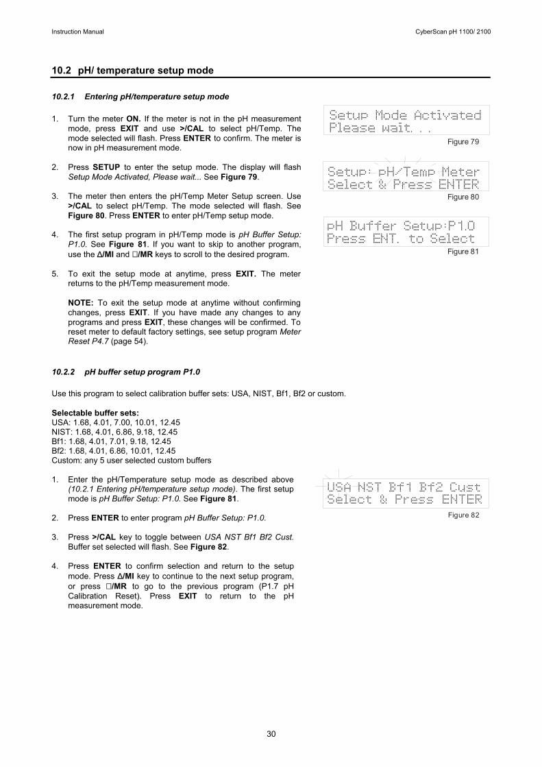
10.2 pH/ temperature setup mode 10.2.1 Entering pH/temperature setup mode 1. Turn the meter ON. If the meter is not in the pH measurement
mode, press EXIT and use >/CAL to select pH/Temp. The mode selected will flash. Press ENTER to confirm. The meter is now in pH measurement mode.
2. Press SETUP to enter the setup mode. The display will flash
Setup Mode Activated, Please wait... See Figure 79. 3. The meter then enters the pH/Temp Meter Setup screen. Use
>/CAL to select pH/Temp. The mode selected will flash. See Figure 80. Press ENTER to enter pH/Temp setup mode.
4. The first setup program in pH/Temp mode is pH Buffer Setup:
P1.0. See Figure 81. If you want to skip to another program, use the ∆/MI and ∇ /MR keys to scroll to the desired program.
5. To exit the setup mode at anytime, press EXIT. The meter
returns to the pH/Temp measurement mode.
NOTE: To exit the setup mode at anytime without confirming changes, press EXIT. If you have made any changes to any programs and press EXIT, these changes will be confirmed. To reset meter to default factory settings, see setup program Meter Reset P4.7 (page 54).
10.2.2 pH buffer setup program P1.0 Use this program to select calibration buffer sets: USA, NIST, Bf1, Bf2 or custom. Selectable buffer sets: USA: 1.68, 4.01, 7.00, 10.01, 12.45 NIST: 1.68, 4.01, 6.86, 9.18, 12.45 Bf1: 1.68, 4.01, 7.01, 9.18, 12.45 Bf2: 1.68, 4.01, 6.86, 10.01, 12.45 Custom: any 5 user selected custom buffers 1. Enter the pH/Temperature setup mode as described above
(10.2.1 Entering pH/temperature setup mode). The first setup mode is pH Buffer Setup: P1.0. See Figure 81.
2. Press ENTER to enter program pH Buffer Setup: P1.0. 3. Press >/CAL key to toggle between USA NST Bf1 Bf2 Cust.
Buffer set selected will flash. See Figure 82. 4. Press ENTER to confirm selection and return to the setup
mode. Press ∆/MI key to continue to the next setup program, or press ∇ /MR to go to the previous program (P1.7 pH Calibration Reset). Press EXIT to return to the pH measurement mode.
Setup: pH/Temp MeterSelect & Press ENTER
pH Buffer Setup:P1.0Press ENT. to Select
Setup Mode ActivatedPlease wait. . .
Figure 79
Figure 80
Figure 81
Figure 82
USA NST Bf1 Bf2 CustSelect & Press ENTER
Instruction Manual CyberScan pH 1100/ 2100
31
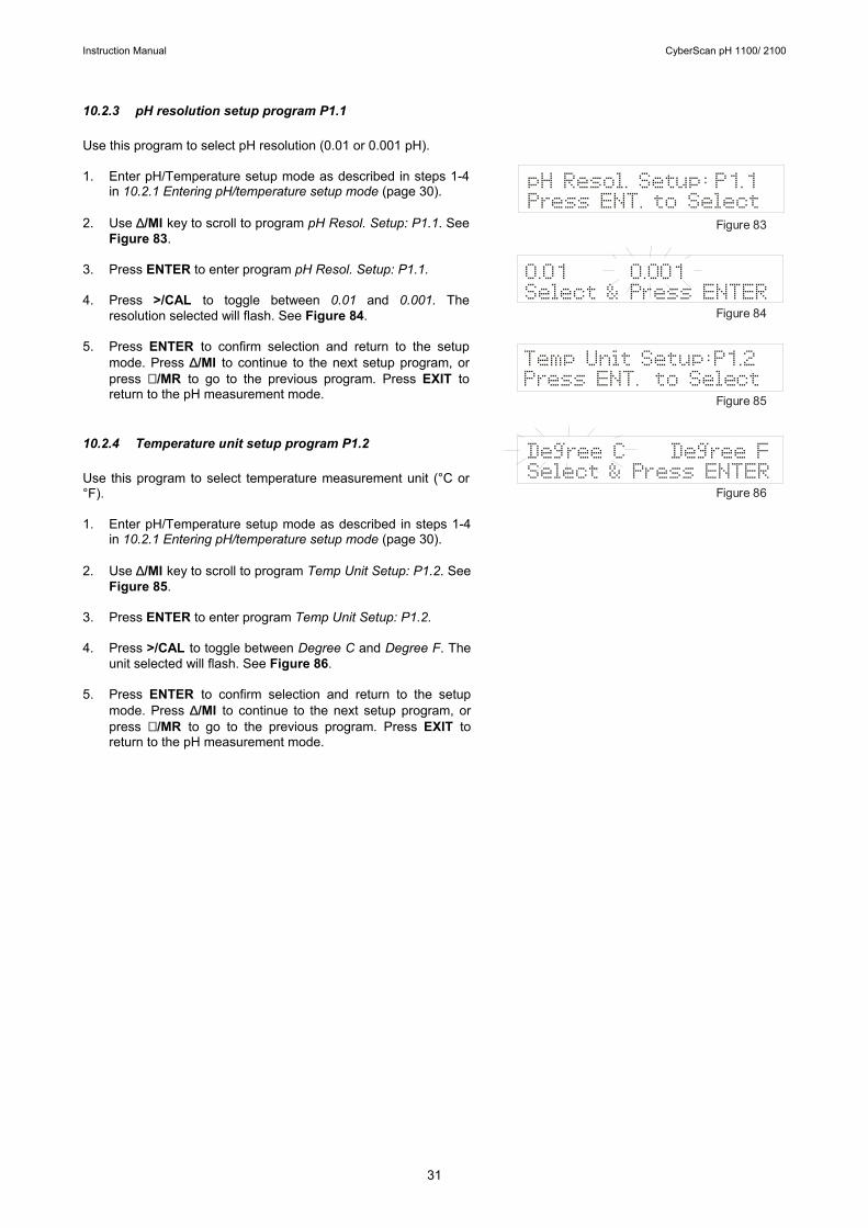
10.2.3 pH resolution setup program P1.1 Use this program to select pH resolution (0.01 or 0.001 pH). 1. Enter pH/Temperature setup mode as described in steps 1-4
in 10.2.1 Entering pH/temperature setup mode (page 30). 2. Use ∆/MI key to scroll to program pH Resol. Setup: P1.1. See
Figure 83. 3. Press ENTER to enter program pH Resol. Setup: P1.1. 4. Press >/CAL to toggle between 0.01 and 0.001. The
resolution selected will flash. See Figure 84. 5. Press ENTER to confirm selection and return to the setup
mode. Press ∆/MI to continue to the next setup program, or press ∇ /MR to go to the previous program. Press EXIT to return to the pH measurement mode.
10.2.4 Temperature unit setup program P1.2 Use this program to select temperature measurement unit (°C or °F). 1. Enter pH/Temperature setup mode as described in steps 1-4
in 10.2.1 Entering pH/temperature setup mode (page 30). 2. Use ∆/MI key to scroll to program Temp Unit Setup: P1.2. See
Figure 85. 3. Press ENTER to enter program Temp Unit Setup: P1.2. 4. Press >/CAL to toggle between Degree C and Degree F. The
unit selected will flash. See Figure 86. 5. Press ENTER to confirm selection and return to the setup
mode. Press ∆/MI to continue to the next setup program, or press ∇ /MR to go to the previous program. Press EXIT to return to the pH measurement mode.
Mode
Degree C Degree FSelect & Press ENTER
0.01 0.001Select & Press ENTER
Temp Unit Setup:P1.2Press ENT. to Select
pH Resol. Setup: P1.1Press ENT. to Select
Figure 83
Figure 84
Figure 85
Figure 86
Instruction Manual CyberScan pH 1100/ 2100
32
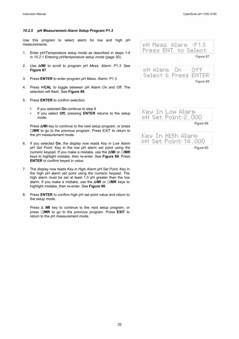
10.2.5 pH Measurement Alarm Setup Program P1.3 Use this program to select alarm for low and high pH measurements. 1. Enter pH/Temperature setup mode as described in steps 1-4
in 10.2.1 Entering pH/temperature setup mode (page 30). 2. Use ∆/MI to scroll to program pH Meas. Alarm: P1.3. See
Figure 87. 3. Press ENTER to enter program pH Meas. Alarm: P1.3. 4. Press >/CAL to toggle between pH Alarm On and Off. The
selection will flash. See Figure 88. 5. Press ENTER to confirm selection.
• If you selected On continue to step 6 • If you select Off, pressing ENTER returns to the setup
mode.
Press ∆/MI key to continue to the next setup program, or press ∇ /MR to go to the previous program. Press EXIT to return to the pH measurement mode.
6. If you selected On, the display now reads Key in Low Alarm
pH Set Point. Key in the low pH alarm set point using the numeric keypad. If you make a mistake, use the ∆/MI or ∇ /MR keys to highlight mistake, then re-enter. See Figure 89. Press ENTER to confirm keyed in value.
7. The display now reads Key in High Alarm pH Set Point. Key in
the high pH alarm set point using the numeric keypad. The high alarm must be set at least 1.0 pH greater than the low alarm. If you make a mistake, use the ∆/MI or ∇ /MR keys to highlight mistake, then re-enter. See Figure 90.
8. Press ENTER to confirm high pH set point value and return to
the setup mode.
Press ∆ /MI key to continue to the next setup program, or press ∇ /MR to go to the previous program. Press EXIT to return to the pH measurement mode.
Figure 89
Figure 90
Key In Low AlarmpH Set Point:2 . 000
Key In High AlarmpH Set Point:14 . 000
pH Meas. Alarm :P1.3Press ENT. to Select
Figure 87
Figure 88
pH Alarm On Select & Press ENTER
Off
Instruction Manual CyberScan pH 1100/ 2100
33
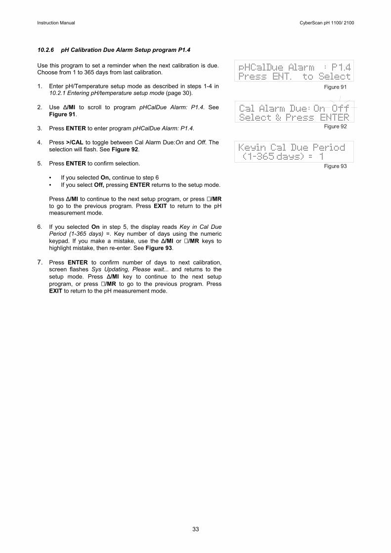
10.2.6 pH Calibration Due Alarm Setup program P1.4 Use this program to set a reminder when the next calibration is due. Choose from 1 to 365 days from last calibration. 1. Enter pH/Temperature setup mode as described in steps 1-4 in
10.2.1 Entering pH/temperature setup mode (page 30). 2. Use ∆/MI to scroll to program pHCalDue Alarm: P1.4. See
Figure 91. 3. Press ENTER to enter program pHCalDue Alarm: P1.4. 4. Press >/CAL to toggle between Cal Alarm Due:On and Off. The
selection will flash. See Figure 92. 5. Press ENTER to confirm selection.
• If you selected On, continue to step 6 • If you select Off, pressing ENTER returns to the setup mode. Press ∆/MI to continue to the next setup program, or press ∇ /MR to go to the previous program. Press EXIT to return to the pH measurement mode.
6. If you selected On in step 5, the display reads Key in Cal Due
Period (1-365 days) =. Key number of days using the numeric keypad. If you make a mistake, use the ∆/MI or ∇ /MR keys to highlight mistake, then re-enter. See Figure 93.
7. Press ENTER to confirm number of days to next calibration,
screen flashes Sys Updating, Please wait... and returns to the setup mode. Press ∆/MI key to continue to the next setup program, or press ∇ /MR to go to the previous program. Press EXIT to return to the pH measurement mode.
Keyin Cal Due Period (1-365 days) = 1
Figure 91
Figure 92
Figure 93
Cal Alarm Due: OnSelect & Press ENTER
Off
pHCalDue Alarm : P1.4Press ENT. to Select
Instruction Manual CyberScan pH 1100/ 2100
34
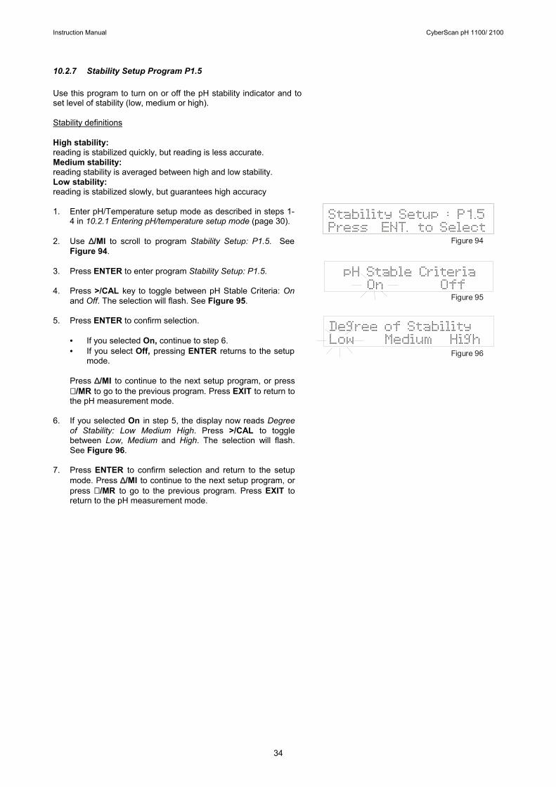
10.2.7 Stability Setup Program P1.5 Use this program to turn on or off the pH stability indicator and to set level of stability (low, medium or high). Stability definitions High stability: reading is stabilized quickly, but reading is less accurate. Medium stability: reading stability is averaged between high and low stability. Low stability: reading is stabilized slowly, but guarantees high accuracy 1. Enter pH/Temperature setup mode as described in steps 1-
4 in 10.2.1 Entering pH/temperature setup mode (page 30). 2. Use ∆/MI to scroll to program Stability Setup: P1.5. See
Figure 94. 3. Press ENTER to enter program Stability Setup: P1.5. 4. Press >/CAL key to toggle between pH Stable Criteria: On
and Off. The selection will flash. See Figure 95. 5. Press ENTER to confirm selection.
• If you selected On, continue to step 6. • If you select Off, pressing ENTER returns to the setup
mode.
Press ∆/MI to continue to the next setup program, or press ∇ /MR to go to the previous program. Press EXIT to return to the pH measurement mode.
6. If you selected On in step 5, the display now reads Degree
of Stability: Low Medium High. Press >/CAL to toggle between Low, Medium and High. The selection will flash. See Figure 96.
7. Press ENTER to confirm selection and return to the setup
mode. Press ∆/MI to continue to the next setup program, or press ∇ /MR to go to the previous program. Press EXIT to return to the pH measurement mode.
Mode
Degree of StabilityLow Medium High
Stability Setup : P1.5Press ENT. to Select
pH Stable Criteria On Off
Figure 94
Figure 95
Figure 96
Instruction Manual CyberScan pH 1100/ 2100
35
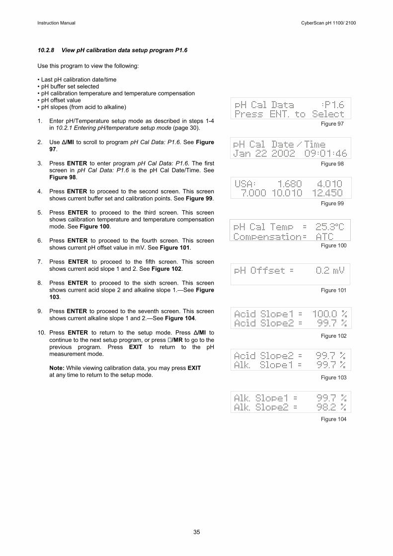
10.2.8 View pH calibration data setup program P1.6 Use this program to view the following: • Last pH calibration date/time • pH buffer set selected • pH calibration temperature and temperature compensation • pH offset value • pH slopes (from acid to alkaline) 1. Enter pH/Temperature setup mode as described in steps 1-4
in 10.2.1 Entering pH/temperature setup mode (page 30). 2. Use ∆/MI to scroll to program pH Cal Data: P1.6. See Figure
97. 3. Press ENTER to enter program pH Cal Data: P1.6. The first
screen in pH Cal Data: P1.6 is the pH Cal Date/Time. See Figure 98.
4. Press ENTER to proceed to the second screen. This screen
shows current buffer set and calibration points. See Figure 99. 5. Press ENTER to proceed to the third screen. This screen
shows calibration temperature and temperature compensation mode. See Figure 100.
6. Press ENTER to proceed to the fourth screen. This screen
shows current pH offset value in mV. See Figure 101. 7. Press ENTER to proceed to the fifth screen. This screen
shows current acid slope 1 and 2. See Figure 102. 8. Press ENTER to proceed to the sixth screen. This screen
shows current acid slope 2 and alkaline slope 1.—See Figure 103.
9. Press ENTER to proceed to the seventh screen. This screen
shows current alkaline slope 1 and 2.—See Figure 104. 10. Press ENTER to return to the setup mode. Press ∆/MI to
continue to the next setup program, or press ∇ /MR to go to the previous program. Press EXIT to return to the pH measurement mode.
Note: While viewing calibration data, you may press EXIT at any time to return to the setup mode.
Figure 97
Figure 98
Figure 99
Figure 100
Figure 101
Figure 102
Figure 103
Figure 104
Acid Slope1 = 100.0 %Acid Slope2 = 99.7 %
USA: 1.680 4.0107.000 10.010 12.450
pH Cal Date /TimeJan 22 2002 09:01:46
pH Cal Data :P1.6Press ENT. to Select
pH Cal Temp = 25.3 CCompensation= ATC
°
pH Offset = 0.2 mV
Acid Slope2 = 99.7 %Alk. Slope1 = 99.7 %
Alk. Slope1 = 99.7 %Alk. Slope2 = 98.2 %
Instruction Manual CyberScan pH 1100/ 2100
36
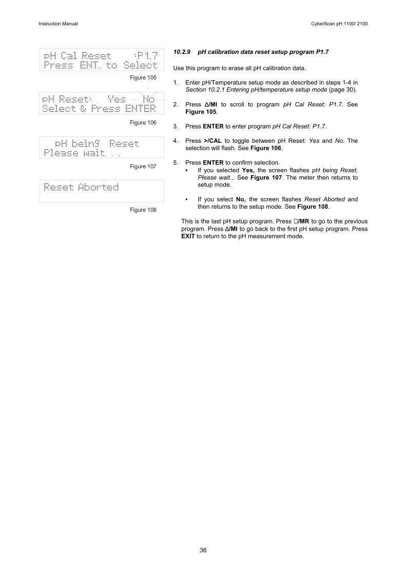
10.2.9 pH calibration data reset setup program P1.7 Use this program to erase all pH calibration data. 1. Enter pH/Temperature setup mode as described in steps 1-4 in
Section 10.2.1 Entering pH/temperature setup mode (page 30). 2. Press ∆/MI to scroll to program pH Cal Reset: P1.7. See
Figure 105. 3. Press ENTER to enter program pH Cal Reset: P1.7. 4. Press >/CAL to toggle between pH Reset: Yes and No. The
selection will flash. See Figure 106. 5. Press ENTER to confirm selection.
• If you selected Yes, the screen flashes pH being Reset, Please wait... See Figure 107. The meter then returns to setup mode.
• If you select No, the screen flashes Reset Aborted and
then returns to the setup mode. See Figure 108.
This is the last pH setup program. Press ∇ /MR to go to the previous program. Press ∆/MI to go back to the first pH setup program. Press EXIT to return to the pH measurement mode.
Reset Aborted
pH being ResetPlease wait. . .
pH Reset: Yes NoSelect & Press ENTER
pH Cal Reset :P1.7Press ENT. to Select
Figure 105
Figure 106
Figure 107
Figure 108
Instruction Manual CyberScan pH 1100/ 2100
37
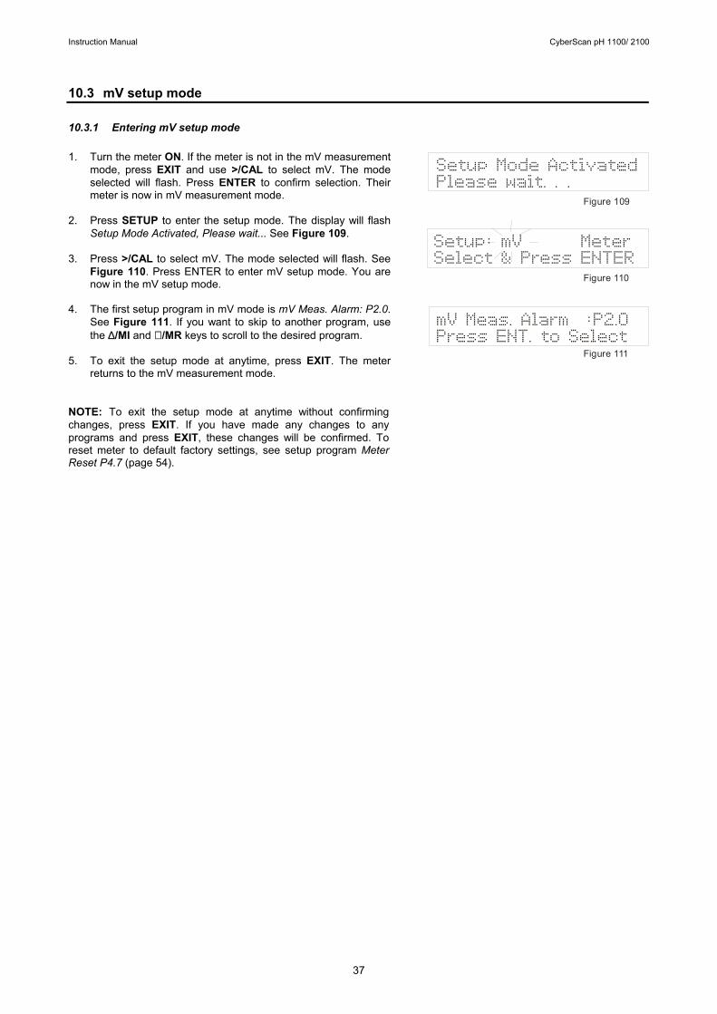
10.3 mV setup mode 10.3.1 Entering mV setup mode 1. Turn the meter ON. If the meter is not in the mV measurement
mode, press EXIT and use >/CAL to select mV. The mode selected will flash. Press ENTER to confirm selection. Their meter is now in mV measurement mode.
2. Press SETUP to enter the setup mode. The display will flash
Setup Mode Activated, Please wait... See Figure 109. 3. Press >/CAL to select mV. The mode selected will flash. See
Figure 110. Press ENTER to enter mV setup mode. You are now in the mV setup mode.
4. The first setup program in mV mode is mV Meas. Alarm: P2.0.
See Figure 111. If you want to skip to another program, use the ∆/MI and ∇ /MR keys to scroll to the desired program.
5. To exit the setup mode at anytime, press EXIT. The meter
returns to the mV measurement mode. NOTE: To exit the setup mode at anytime without confirming changes, press EXIT. If you have made any changes to any programs and press EXIT, these changes will be confirmed. To reset meter to default factory settings, see setup program Meter Reset P4.7 (page 54).
mV Meas. Alarm :P2.0Press ENT. to Select
Setup Mode ActivatedPlease wait. . .
Setup: mV MeterSelect & Press ENTER
Figure 109
Figure 110
Figure 111
Instruction Manual CyberScan pH 1100/ 2100
38
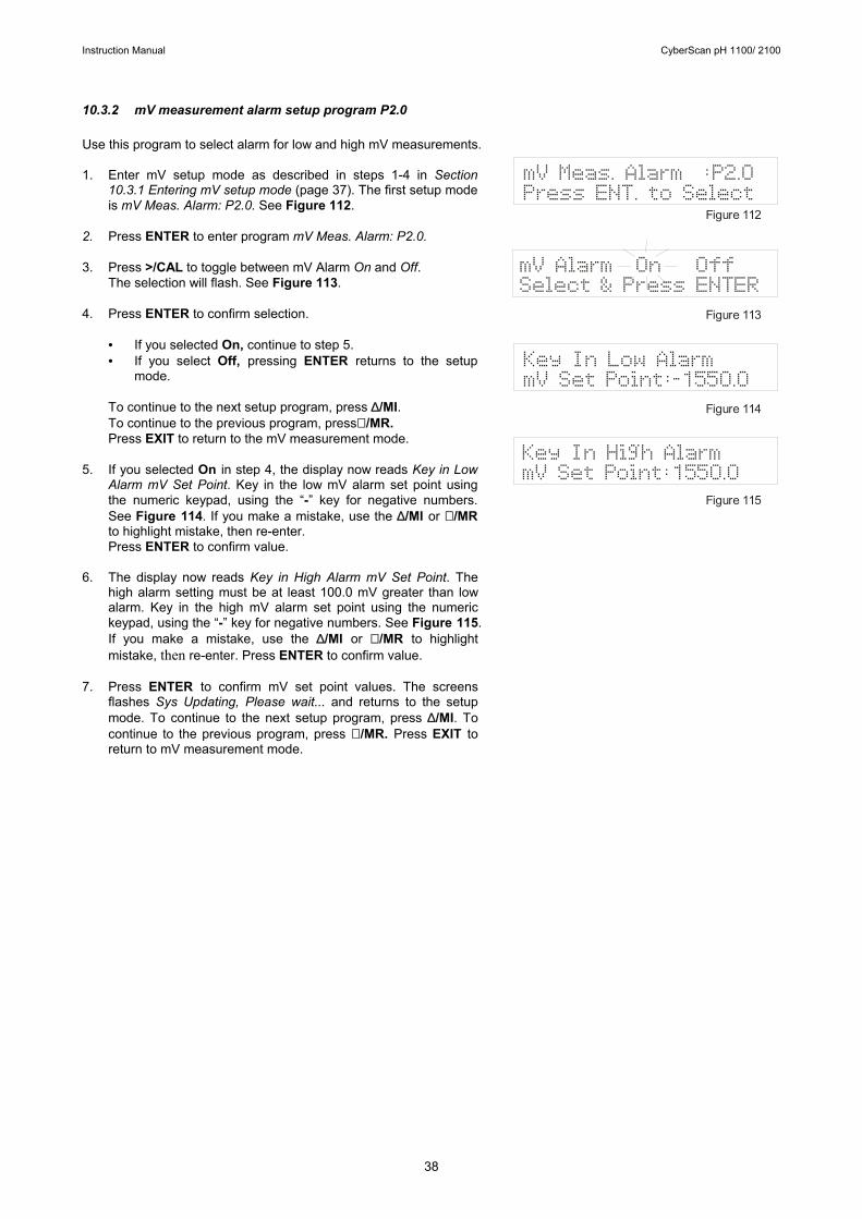
10.3.2 mV measurement alarm setup program P2.0 Use this program to select alarm for low and high mV measurements. 1. Enter mV setup mode as described in steps 1-4 in Section
10.3.1 Entering mV setup mode (page 37). The first setup mode is mV Meas. Alarm: P2.0. See Figure 112.
2. Press ENTER to enter program mV Meas. Alarm: P2.0. 3. Press >/CAL to toggle between mV Alarm On and Off.
The selection will flash. See Figure 113. 4. Press ENTER to confirm selection.
• If you selected On, continue to step 5. • If you select Off, pressing ENTER returns to the setup
mode.
To continue to the next setup program, press ∆/MI. To continue to the previous program, press∇ /MR. Press EXIT to return to the mV measurement mode.
5. If you selected On in step 4, the display now reads Key in Low
Alarm mV Set Point. Key in the low mV alarm set point using the numeric keypad, using the “-” key for negative numbers. See Figure 114. If you make a mistake, use the ∆/MI or ∇ /MR to highlight mistake, then re-enter. Press ENTER to confirm value.
6. The display now reads Key in High Alarm mV Set Point. The
high alarm setting must be at least 100.0 mV greater than low alarm. Key in the high mV alarm set point using the numeric keypad, using the “-” key for negative numbers. See Figure 115. If you make a mistake, use the ∆/MI or ∇ /MR to highlight mistake, then re-enter. Press ENTER to confirm value.
7. Press ENTER to confirm mV set point values. The screens
flashes Sys Updating, Please wait... and returns to the setup mode. To continue to the next setup program, press ∆/MI. To continue to the previous program, press ∇ /MR. Press EXIT to return to mV measurement mode.
8. Setup
Key In Low AlarmmV Set Point:-1550.0
mV Alarm On OffSelect & Press ENTER
mV Meas. Alarm :P2.0Press ENT. to Select
Figure 112
Figure 113
Figure 1
Figure 115
14
Key In High AlarmmV Set Point:1550.0
Instruction Manual CyberScan pH 1100/ 2100
39
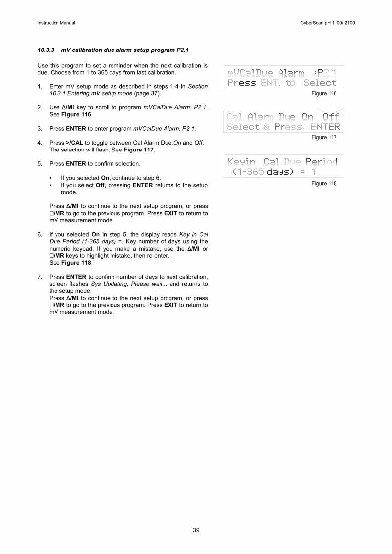
10.3.3 mV calibration due alarm setup program P2.1 Use this program to set a reminder when the next calibration is due. Choose from 1 to 365 days from last calibration. 1. Enter mV setup mode as described in steps 1-4 in Section
10.3.1 Entering mV setup mode (page 37). 2. Use ∆/MI key to scroll to program mVCalDue Alarm: P2.1.
See Figure 116. 3. Press ENTER to enter program mVCalDue Alarm: P2.1. 4. Press >/CAL to toggle between Cal Alarm Due:On and Off.
The selection will flash. See Figure 117. 5. Press ENTER to confirm selection.
• If you selected On, continue to step 6. • If you select Off, pressing ENTER returns to the setup
mode. Press ∆/MI to continue to the next setup program, or press ∇ /MR to go to the previous program. Press EXIT to return to mV measurement mode.
6. If you selected On in step 5, the display reads Key in Cal
Due Period (1-365 days) =. Key number of days using the numeric keypad. If you make a mistake, use the ∆/MI or ∇ /MR keys to highlight mistake, then re-enter. See Figure 118.
7. Press ENTER to confirm number of days to next calibration,
screen flashes Sys Updating, Please wait... and returns to the setup mode. Press ∆/MI to continue to the next setup program, or press ∇ /MR to go to the previous program. Press EXIT to return to mV measurement mode.
Keyin Cal Due Period (1-365 days) = 1
Cal Alarm Due On OffSelect & Press ENTER
mVCalDue Alarm :P2.1Press ENT. to Select
Figure 116
Figure 117
Figure 118
Instruction Manual CyberScan pH 1100/ 2100
40
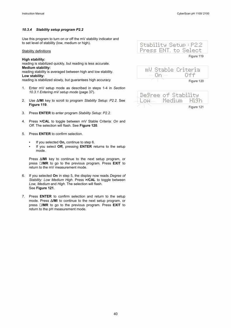
10.3.4 Stability setup program P2.2 Use this program to turn on or off the mV stability indicator and to set level of stability (low, medium or high). Stability definitions High stability: reading is stabilized quickly, but reading is less accurate. Medium stability: reading stability is averaged between high and low stability. Low stability: reading is stabilized slowly, but guarantees high accuracy 1. Enter mV setup mode as described in steps 1-4 in Section
10.3.1 Entering mV setup mode (page 37). 2. Use ∆/MI key to scroll to program Stability Setup: P2.2. See
Figure 119. 3. Press ENTER to enter program Stability Setup: P2.2. 4. Press >/CAL to toggle between mV Stable Criteria: On and
Off. The selection will flash. See Figure 120. 5. Press ENTER to confirm selection.
• If you selected On, continue to step 6. • If you select Off, pressing ENTER returns to the setup
mode.
Press ∆/MI key to continue to the next setup program, or press ∇ /MR to go to the previous program. Press EXIT to return to the mV measurement mode.
6. If you selected On in step 5, the display now reads Degree of
Stability: Low Medium High. Press >/CAL to toggle between Low, Medium and High. The selection will flash. See Figure 121.
7. Press ENTER to confirm selection and return to the setup
mode. Press ∆/MI to continue to the next setup program, or press ∇ /MR to go to the previous program. Press EXIT to return to the pH measurement mode.
Degree of StabilityLow Medium High
mV Stable Criteria On Off
Stability Setup : P2.2Press ENT. to Select
Figure 119
Figure 120
Figure 121
Instruction Manual CyberScan pH 1100/ 2100
41
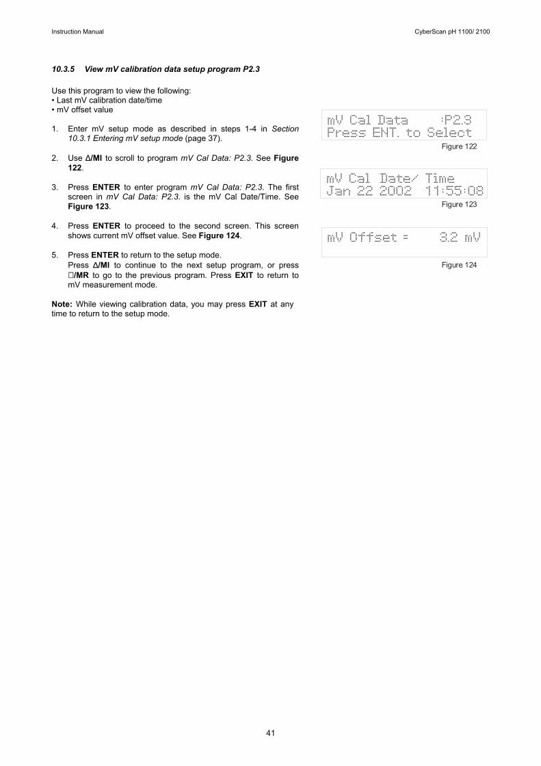
10.3.5 View mV calibration data setup program P2.3 Use this program to view the following: • Last mV calibration date/time • mV offset value 1. Enter mV setup mode as described in steps 1-4 in Section
10.3.1 Entering mV setup mode (page 37). 2. Use ∆/MI to scroll to program mV Cal Data: P2.3. See Figure
122. 3. Press ENTER to enter program mV Cal Data: P2.3. The first
screen in mV Cal Data: P2.3. is the mV Cal Date/Time. See Figure 123.
4. Press ENTER to proceed to the second screen. This screen
shows current mV offset value. See Figure 124. 5. Press ENTER to return to the setup mode.
Press ∆/MI to continue to the next setup program, or press ∇ /MR to go to the previous program. Press EXIT to return to mV measurement mode.
Note: While viewing calibration data, you may press EXIT at any time to return to the setup mode.
mV Offset = 3.2 mV
mV Cal Date/ TimeJan 22 2002 11:55:08
mV Cal Data :P2.3Press ENT. to Select
Figure 122
Figure 123
Figure 124
Instruction Manual CyberScan pH 1100/ 2100
42
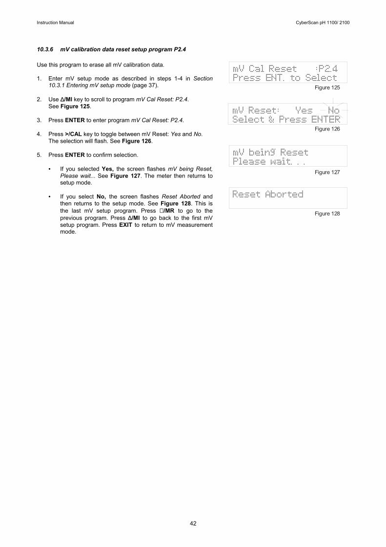
10.3.6 mV calibration data reset setup program P2.4 Use this program to erase all mV calibration data. 1. Enter mV setup mode as described in steps 1-4 in Section
10.3.1 Entering mV setup mode (page 37). 2. Use ∆/MI key to scroll to program mV Cal Reset: P2.4.
See Figure 125. 3. Press ENTER to enter program mV Cal Reset: P2.4. 4. Press >/CAL key to toggle between mV Reset: Yes and No.
The selection will flash. See Figure 126. 5. Press ENTER to confirm selection.
• If you selected Yes, the screen flashes mV being Reset, Please wait... See Figure 127. The meter then returns to setup mode.
• If you select No, the screen flashes Reset Aborted and
then returns to the setup mode. See Figure 128. This is the last mV setup program. Press ∇ /MR to go to the previous program. Press ∆/MI to go back to the first mV setup program. Press EXIT to return to mV measurement mode.
Reset Aborted
mV being ResetPlease wait. . .
mV Reset: Yes NoSelect & Press ENTER
mV Cal Reset :P2.4Press ENT. to Select
Figure 125
Figure 126
Figure 127
Figure 128
Instruction Manual CyberScan pH 1100/ 2100
43
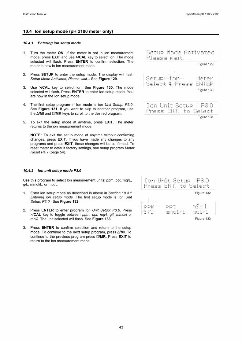
10.4 Ion setup mode (pH 2100 meter only) 10.4.1 Entering ion setup mode 1. Turn the meter ON. If the meter is not in ion measurement
mode, press EXIT and use >/CAL key to select ion. The mode selected will flash. Press ENTER to confirm selection. The meter is now in Ion measurement mode.
2. Press SETUP to enter the setup mode. The display will flash
Setup Mode Activated, Please wait... See Figure 129. 3. Use >/CAL key to select ion. See Figure 130. The mode
selected will flash. Press ENTER to enter Ion setup mode. You are now in the Ion setup mode.
4. The first setup program in Ion mode is Ion Unit Setup: P3.0.
See Figure 131. If you want to skip to another program, use the ∆/MI and ∇ /MR keys to scroll to the desired program.
5. To exit the setup mode at anytime, press EXIT. The meter
returns to the ion measurement mode.
NOTE: To exit the setup mode at anytime without confirming changes, press EXIT. If you have made any changes to any programs and press EXIT, these changes will be confirmed. To reset meter to default factory settings, see setup program Meter Reset P4.7 (page 54).
10.4.2 Ion unit setup mode P3.0 Use this program to select Ion measurement units: ppm, ppt, mg/L, g/L, mmol/L, or mol/L 1. Enter ion setup mode as described in above in Section 10.4.1
Entering ion setup mode. The first setup mode is Ion Unit Setup: P3.0 See Figure 132.
2. Press ENTER to enter program Ion Unit Setup: P3.0. Press
>/CAL key to toggle between ppm, ppt, mg/l, g/l, mmol/l or mol/l. The unit selected will flash. See Figure 133.
3. Press ENTER to confirm selection and return to the setup
mode. To continue to the next setup program, press ∆/MI. To continue to the previous program press ∇ /MR. Press EXIT to return to the ion measurement mode.
Setup: Ion MeterSelect & Press ENTER
Setup Mode ActivatedPlease wait. . .
Figure 129
Figure 130
Figure 131
Ion Unit Setup : P3.0Press ENT. to Select
ppm ppt mg/1g/l mmol/l mol/l
Ion Unit Setup :P3.0Press ENT. to Select
Figure 132
Figure 133
Instruction Manual CyberScan pH 1100/ 2100
44
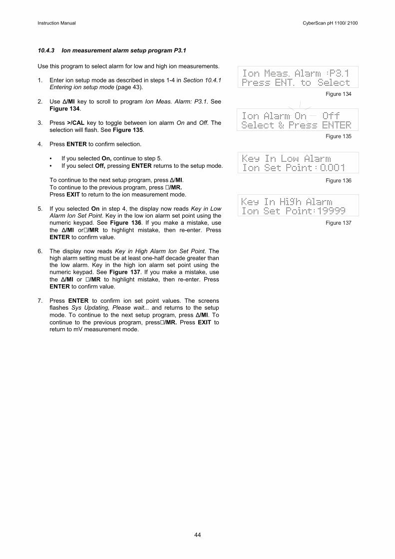
10.4.3 Ion measurement alarm setup program P3.1 Use this program to select alarm for low and high ion measurements. 1. Enter ion setup mode as described in steps 1-4 in Section 10.4.1
Entering ion setup mode (page 43). 2. Use ∆/MI key to scroll to program Ion Meas. Alarm: P3.1. See
Figure 134. 3. Press >/CAL key to toggle between ion alarm On and Off. The
selection will flash. See Figure 135. 4. Press ENTER to confirm selection.
• If you selected On, continue to step 5. • If you select Off, pressing ENTER returns to the setup mode. To continue to the next setup program, press ∆/MI. To continue to the previous program, press ∇ /MR. Press EXIT to return to the ion measurement mode.
5. If you selected On in step 4, the display now reads Key in Low
Alarm Ion Set Point. Key in the low ion alarm set point using the numeric keypad. See Figure 136. If you make a mistake, use the ∆/MI or∇ /MR to highlight mistake, then re-enter. Press ENTER to confirm value.
6. The display now reads Key in High Alarm Ion Set Point. The
high alarm setting must be at least one-half decade greater than the low alarm. Key in the high ion alarm set point using the numeric keypad. See Figure 137. If you make a mistake, use the ∆/MI or ∇ /MR to highlight mistake, then re-enter. Press ENTER to confirm value.
7. Press ENTER to confirm ion set point values. The screens
flashes Sys Updating, Please wait... and returns to the setup mode. To continue to the next setup program, press ∆/MI. To continue to the previous program, press∇ /MR. Press EXIT to return to mV measurement mode.
Ion Alarm On OffSelect & Press ENTER
Ion Meas. Alarm :P3.1Press ENT. to Select
Figure 134
Figure 135
Figure 136
Figure 137
Key In High AlarmIon Set Point:19999
Key In Low AlarmIon Set Point : 0.001
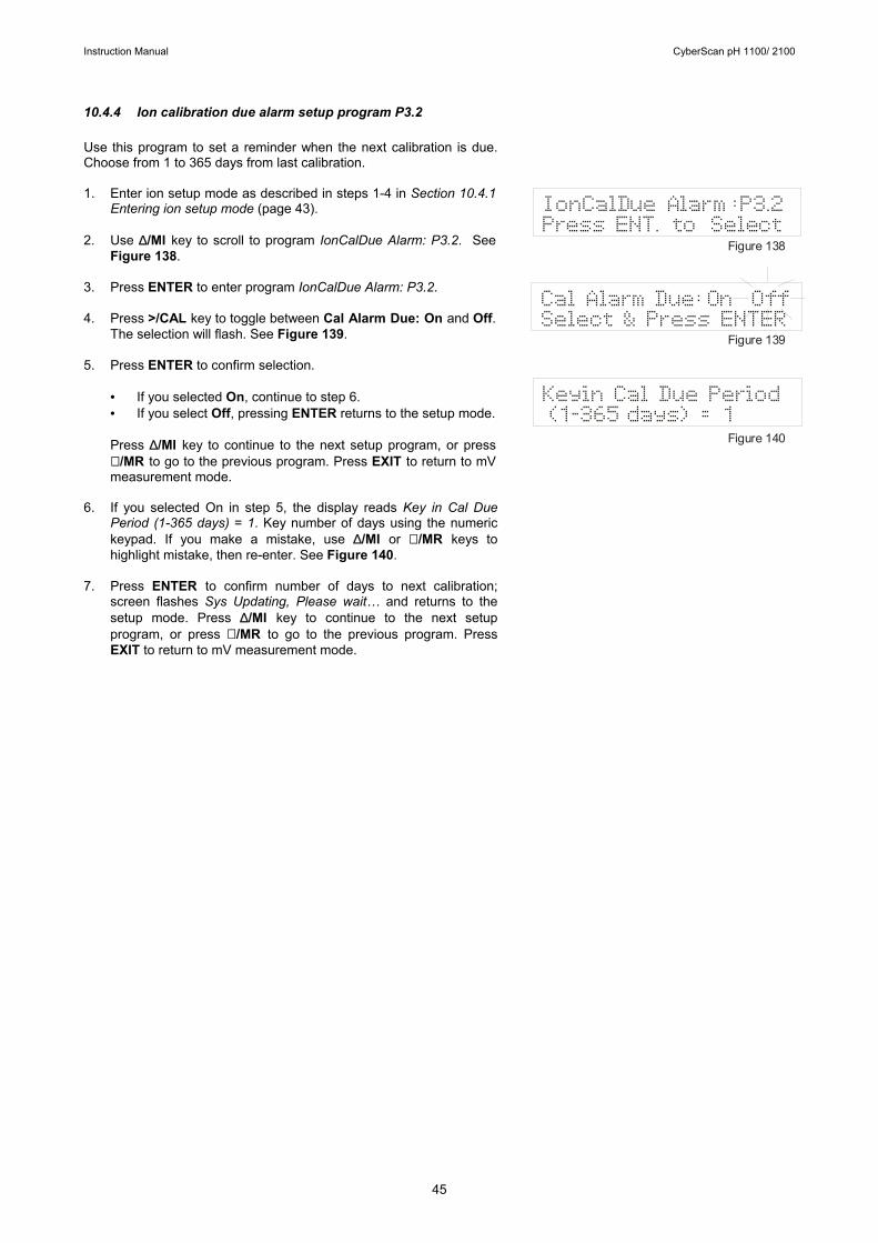
Instruction Manual CyberScan pH 1100/ 2100
45
10.4.4 Ion calibration due alarm setup program P3.2 Use this program to set a reminder when the next calibration is due. Choose from 1 to 365 days from last calibration. 1. Enter ion setup mode as described in steps 1-4 in Section 10.4.1
Entering ion setup mode (page 43). 2. Use ∆/MI key to scroll to program IonCalDue Alarm: P3.2. See
Figure 138. 3. Press ENTER to enter program IonCalDue Alarm: P3.2. 4. Press >/CAL key to toggle between Cal Alarm Due: On and Off.
The selection will flash. See Figure 139. 5. Press ENTER to confirm selection.
• If you selected On, continue to step 6. • If you select Off, pressing ENTER returns to the setup mode. Press ∆/MI key to continue to the next setup program, or press ∇ /MR to go to the previous program. Press EXIT to return to mV measurement mode.
6. If you selected On in step 5, the display reads Key in Cal Due
Period (1-365 days) = 1. Key number of days using the numeric keypad. If you make a mistake, use ∆/MI or ∇ /MR keys to highlight mistake, then re-enter. See Figure 140.
7. Press ENTER to confirm number of days to next calibration;
screen flashes Sys Updating, Please wait… and returns to the setup mode. Press ∆/MI key to continue to the next setup program, or press ∇ /MR to go to the previous program. Press EXIT to return to mV measurement mode.
Keyin Cal Due Period(1-365 days) = 1
Cal Alarm Due:On OffSelect & Press ENTER
IonCalDue Alarm :P3.2Press ENT. to Select
Figure 138
Figure 139
Figure 140
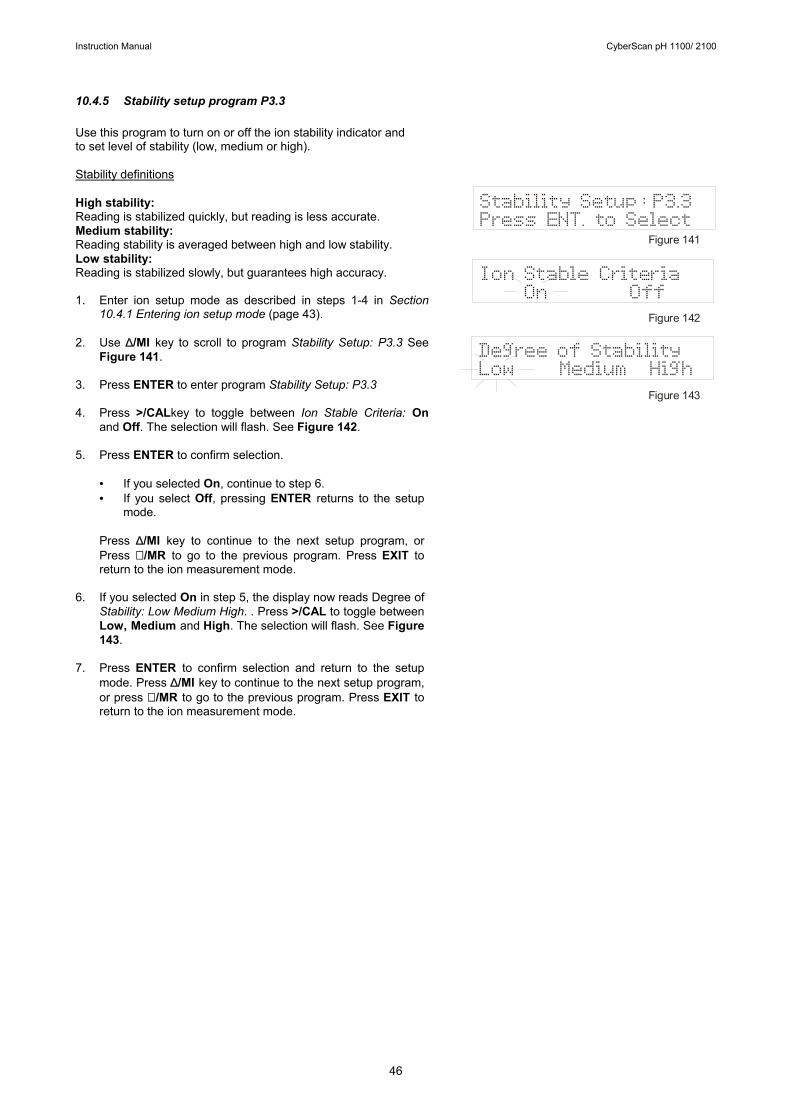
Instruction Manual CyberScan pH 1100/ 2100
46
10.4.5 Stability setup program P3.3 Use this program to turn on or off the ion stability indicator and to set level of stability (low, medium or high). Stability definitions High stability: Reading is stabilized quickly, but reading is less accurate. Medium stability: Reading stability is averaged between high and low stability. Low stability: Reading is stabilized slowly, but guarantees high accuracy. 1. Enter ion setup mode as described in steps 1-4 in Section
10.4.1 Entering ion setup mode (page 43). 2. Use ∆/MI key to scroll to program Stability Setup: P3.3 See
Figure 141. 3. Press ENTER to enter program Stability Setup: P3.3 4. Press >/CALkey to toggle between Ion Stable Criteria: On
and Off. The selection will flash. See Figure 142. 5. Press ENTER to confirm selection.
• If you selected On, continue to step 6. • If you select Off, pressing ENTER returns to the setup
mode. Press ∆/MI key to continue to the next setup program, or Press ∇ /MR to go to the previous program. Press EXIT to return to the ion measurement mode.
6. If you selected On in step 5, the display now reads Degree of
Stability: Low Medium High. . Press >/CAL to toggle between Low, Medium and High. The selection will flash. See Figure 143.
7. Press ENTER to confirm selection and return to the setup
mode. Press ∆/MI key to continue to the next setup program, or press ∇ /MR to go to the previous program. Press EXIT to return to the ion measurement mode.
Ion Stable Criteria On Off
Degree of StabilityLow Medium High
Stability Setup : P3.3Press ENT. to Select
Figure 141
Figure 142
Figure 143

Instruction Manual CyberScan pH 1100/ 2100
47
10.4.6 Ion mode setup program P3.4 Use this program to select high or low ion resolution mode. High resolution has ±500 mV value, low has ±1850 mV value. 1. Enter ion setup mode as described in steps 1-4 in Section
10.4.1 Entering ion setup mode (page 43). 2. Use ∆/MI key to scroll to program Ion Mode Setup: P3.4. See
Figure 144. 3. Press ENTER to enter program Ion Mode Setup: P3.4. 4. Press >/CAL to toggle between High or Low. The unit
selected will flash. See Figure 145. 5. Press ENTER to confirm selection and return to the setup
mode. 6. Press ∆/MI key to continue to the next setup program, or
press ∇ /MR to go to the previous program. Press EXIT to return to the ion measurement mode.
Resolution: High LowSelect & Press ENTER
Ion Mode Setup : P3.4Press ENT. to Select
Figure 144
Figure 145
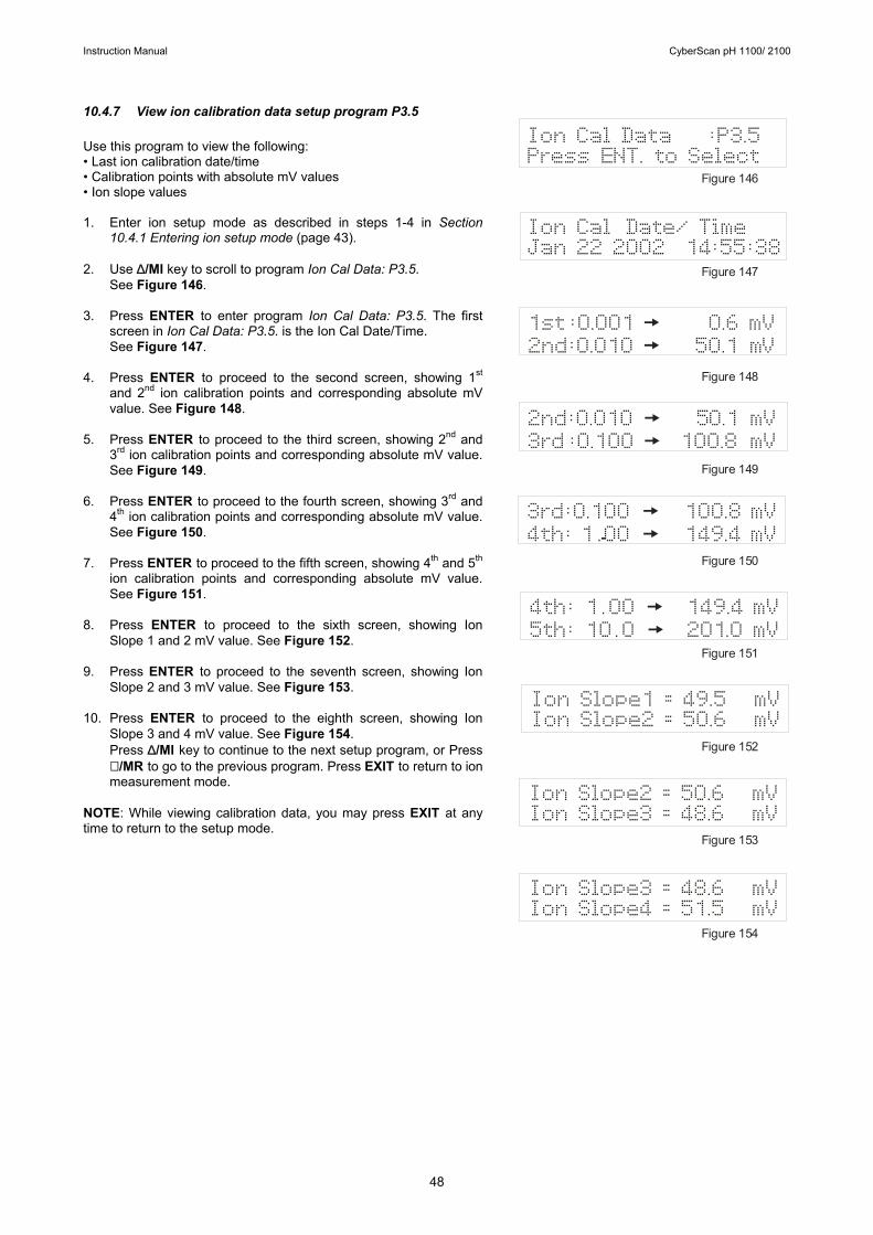
Instruction Manual CyberScan pH 1100/ 2100
48
10.4.7 View ion calibration data setup program P3.5 Use this program to view the following: • Last ion calibration date/time • Calibration points with absolute mV values • Ion slope values 1. Enter ion setup mode as described in steps 1-4 in Section
10.4.1 Entering ion setup mode (page 43). 2. Use ∆/MI key to scroll to program Ion Cal Data: P3.5.
See Figure 146. 3. Press ENTER to enter program Ion Cal Data: P3.5. The first
screen in Ion Cal Data: P3.5. is the Ion Cal Date/Time. See Figure 147.
4. Press ENTER to proceed to the second screen, showing 1st
and 2nd ion calibration points and corresponding absolute mV value. See Figure 148.
5. Press ENTER to proceed to the third screen, showing 2nd and
3rd ion calibration points and corresponding absolute mV value. See Figure 149.
6. Press ENTER to proceed to the fourth screen, showing 3rd and
4th ion calibration points and corresponding absolute mV value. See Figure 150.
7. Press ENTER to proceed to the fifth screen, showing 4th and 5th
ion calibration points and corresponding absolute mV value. See Figure 151.
8. Press ENTER to proceed to the sixth screen, showing Ion
Slope 1 and 2 mV value. See Figure 152. 9. Press ENTER to proceed to the seventh screen, showing Ion
Slope 2 and 3 mV value. See Figure 153. 10. Press ENTER to proceed to the eighth screen, showing Ion
Slope 3 and 4 mV value. See Figure 154. Press ∆/MI key to continue to the next setup program, or Press ∇ /MR to go to the previous program. Press EXIT to return to ion measurement mode.
NOTE: While viewing calibration data, you may press EXIT at any time to return to the setup mode.
Ion Cal Data :P3.5Press ENT. to Select
1st:0.001 0.6 mV2nd:0.010 50.1 mV
Figure 146
Figure 147
Figure 148
Figure 149
Figure 150
Figure 151
Figure 152
Figure 153
Figure 154
Ion Cal Date/ TimeJan 22 2002 14:55:38
2nd:0.010 50.1 mV3rd :0.100 100.8 mV
3rd:0.100 100.8 mV4th: 1 .00 149.4 mV
4th: 1.00 149.4 mV5th: 10.0 201.0 mV
Ion Slope1 = 49.5 mVIon Slope2 = 50.6 mV
Ion Slope2 = 50.6 mVIon Slope3 = 48.6 mV
Ion Slope3 = 48.6 mVIon Slope4 = 51.5 mV
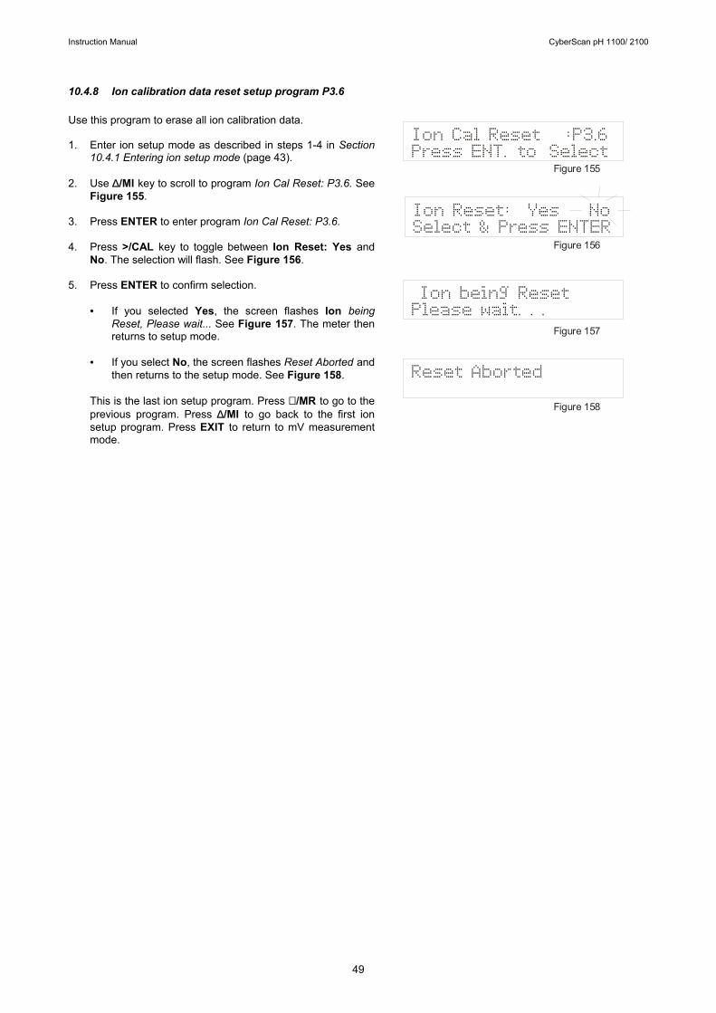
Instruction Manual CyberScan pH 1100/ 2100
49
10.4.8 Ion calibration data reset setup program P3.6 Use this program to erase all ion calibration data. 1. Enter ion setup mode as described in steps 1-4 in Section
10.4.1 Entering ion setup mode (page 43). 2. Use ∆/MI key to scroll to program Ion Cal Reset: P3.6. See
Figure 155. 3. Press ENTER to enter program Ion Cal Reset: P3.6. 4. Press >/CAL key to toggle between Ion Reset: Yes and
No. The selection will flash. See Figure 156. 5. Press ENTER to confirm selection.
• If you selected Yes, the screen flashes Ion being Reset, Please wait... See Figure 157. The meter then returns to setup mode.
• If you select No, the screen flashes Reset Aborted and
then returns to the setup mode. See Figure 158.
This is the last ion setup program. Press ∇ /MR to go to the previous program. Press ∆/MI to go back to the first ion setup program. Press EXIT to return to mV measurement mode.
Mode
Ion being ResetPlease wait. . .
Ion Reset: Yes NoSelect & Press ENTER
Ion Cal Reset :P3.6Press ENT. to Select
Figure 155
Figure 156
Figure 157
Figure 158
Reset Aborted
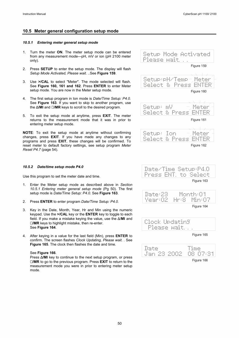
Instruction Manual CyberScan pH 1100/ 2100
50
10.5 Meter general configuration setup mode 10.5.1 Entering meter general setup mode 1. Turn the meter ON. The meter setup mode can be entered
from any measurement mode—pH, mV or ion (pH 2100 meter only).
2. Press SETUP to enter the setup mode. The display will flash
Setup Mode Activated, Please wait. ..See Figure 159. 3. Use >/CAL to select "Meter". The mode selected will flash.
See Figure 160, 161 and 162. Press ENTER to enter Meter setup mode. You are now in the Meter setup mode.
4. The first setup program in Ion mode is Date/Time Setup: P4.0.
See Figure 163. If you want to skip to another program, use the ∆/MI and ∇ /MR keys to scroll to the desired program.
5. To exit the setup mode at anytime, press EXIT. The meter
returns to the measurement mode that it was in prior to entering meter setup mode.
NOTE: To exit the setup mode at anytime without confirming changes, press EXIT. If you have made any changes to any programs and press EXIT, these changes will be confirmed. To reset meter to default factory settings, see setup program Meter Reset P4.7 (page 54). 10.5.2 Date/time setup mode P4.0 Use this program to set the meter date and time. 1. Enter the Meter setup mode as described above in Section
10.5.1 Entering meter general setup mode (Pg 50). The first setup mode is Date/Time Setup: P4.0. See Figure 163.
2. Press ENTER to enter program Date/Time Setup: P4.0. 3. Key in the Date, Month, Year, Hr and Min using the numeric
keypad. Use the >/CAL key or the ENTER key to toggle to each field. If you make a mistake keying the value, use the ∆/MI and ∇ /MR keys to highlight mistake, then re-enter. See Figure 164.
4. After keying in a value for the last field (Min), press ENTER to
confirm. The screen flashes Clock Updating, Please wait. . See Figure 165. The clock then flashes the date and time.
See Figure 166. Press ∆/MI key to continue to the next setup program, or press ∇ /MR to go to the previous program. Press EXIT to return to the measurement mode you were in prior to entering meter setup mode.
Setup: mV MeterSelect & Press ENTER
Setup:pH/Temp MeterSelect & Press ENTER
Setup Mode ActivatedPlease wait. . .
Figure 159
Figure 160
Figure 161
Figure 162
Setup: Ion MeterSelect & Press ENTER
Clock UpdatingPlease wait. . .
Date:23 Month:01Year:02 Hr:8 Min:07
Date/Time Setup:P4.0Press ENT. to Select
Figure 163
Figure 164
Figure 165
Figure 166
Date TimeJan 23 2002 08”07:31
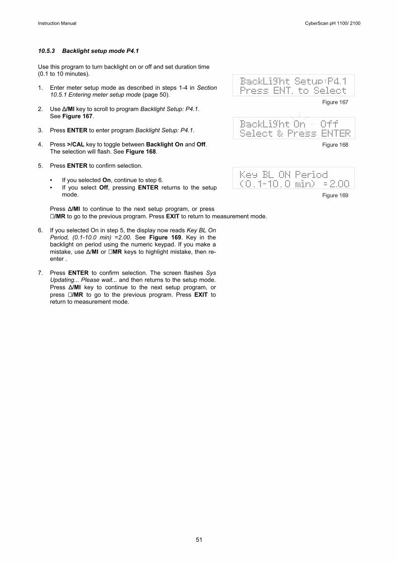
Instruction Manual CyberScan pH 1100/ 2100
51
10.5.3 Backlight setup mode P4.1 Use this program to turn backlight on or off and set duration time (0.1 to 10 minutes). 1. Enter meter setup mode as described in steps 1-4 in Section
10.5.1 Entering meter setup mode (page 50). 2. Use ∆/MI key to scroll to program Backlight Setup: P4.1.
See Figure 167. 3. Press ENTER to enter program Backlight Setup: P4.1. 4. Press >/CAL key to toggle between Backlight On and Off.
The selection will flash. See Figure 168. 5. Press ENTER to confirm selection.
• If you selected On, continue to step 6. • If you select Off, pressing ENTER returns to the setup
mode. Press ∆/MI to continue to the next setup program, or press ∇ /MR to go to the previous program. Press EXIT to return to measurement mode.
6. If you selected On in step 5, the display now reads Key BL On
Period, (0.1-10.0 min) =2.00. See Figure 169. Key in the backlight on period using the numeric keypad. If you make a mistake, use ∆/MI or ∇ MR keys to highlight mistake, then re-enter .
7. Press ENTER to confirm selection. The screen flashes Sys
Updating... Please wait... and then returns to the setup mode. Press ∆/MI key to continue to the next setup program, or press ∇ /MR to go to the previous program. Press EXIT to return to measurement mode.
BackLight Setup:P4.1Press ENT. to Select
BackLight On Off Select & Press ENTER
Key BL ON Period(0 .1-10 . 0 min) = 2.00
Figure 167
Figure 168
Figure 169
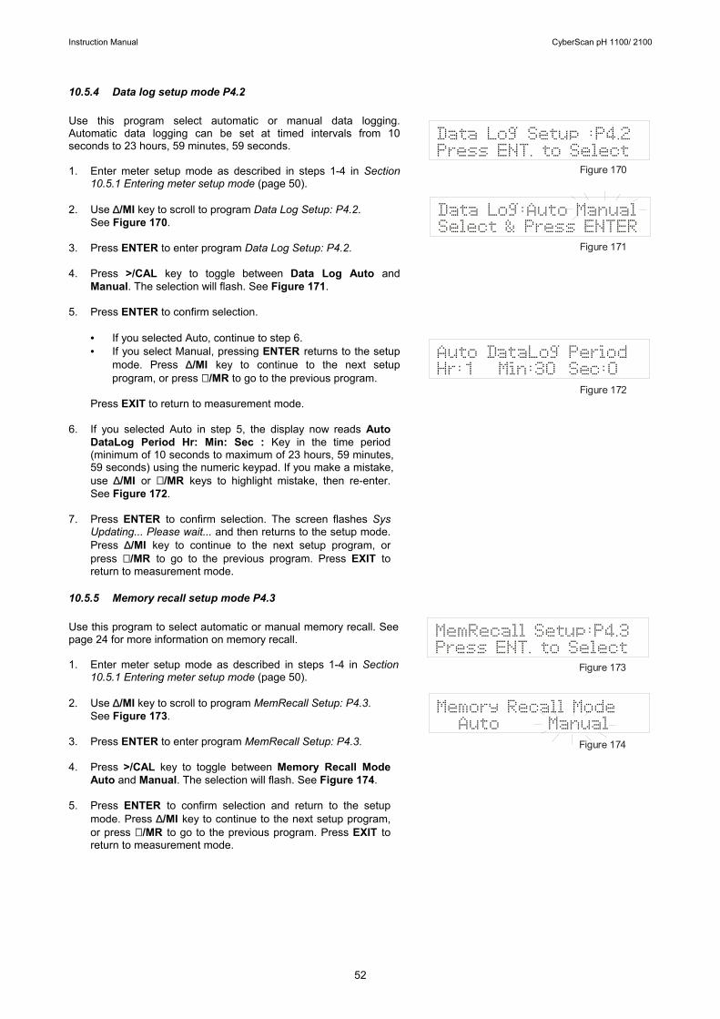
Instruction Manual CyberScan pH 1100/ 2100
52
10.5.4 Data log setup mode P4.2 Use this program select automatic or manual data logging. Automatic data logging can be set at timed intervals from 10 seconds to 23 hours, 59 minutes, 59 seconds. 1. Enter meter setup mode as described in steps 1-4 in Section
10.5.1 Entering meter setup mode (page 50). 2. Use ∆/MI key to scroll to program Data Log Setup: P4.2.
See Figure 170. 3. Press ENTER to enter program Data Log Setup: P4.2. 4. Press >/CAL key to toggle between Data Log Auto and
Manual. The selection will flash. See Figure 171. 5. Press ENTER to confirm selection.
• If you selected Auto, continue to step 6. • If you select Manual, pressing ENTER returns to the setup
mode. Press ∆/MI key to continue to the next setup program, or press ∇ /MR to go to the previous program.
Press EXIT to return to measurement mode.
6. If you selected Auto in step 5, the display now reads Auto
DataLog Period Hr: Min: Sec : Key in the time period (minimum of 10 seconds to maximum of 23 hours, 59 minutes, 59 seconds) using the numeric keypad. If you make a mistake, use ∆/MI or ∇ /MR keys to highlight mistake, then re-enter. See Figure 172.
7. Press ENTER to confirm selection. The screen flashes Sys
Updating... Please wait... and then returns to the setup mode. Press ∆/MI key to continue to the next setup program, or press ∇ /MR to go to the previous program. Press EXIT to return to measurement mode.
10.5.5 Memory recall setup mode P4.3 Use this program to select automatic or manual memory recall. See page 24 for more information on memory recall. 1. Enter meter setup mode as described in steps 1-4 in Section
10.5.1 Entering meter setup mode (page 50). 2. Use ∆/MI key to scroll to program MemRecall Setup: P4.3.
See Figure 173. 3. Press ENTER to enter program MemRecall Setup: P4.3. 4. Press >/CAL key to toggle between Memory Recall Mode
Auto and Manual. The selection will flash. See Figure 174. 5. Press ENTER to confirm selection and return to the setup
mode. Press ∆/MI key to continue to the next setup program, or press ∇ /MR to go to the previous program. Press EXIT to return to measurement mode.
Auto DataLog PeriodHr:1 Min:30 Sec:0
Data Log:Auto ManualSelect & Press ENTER
Data Log Setup :P4.2Press ENT. to Select
Figure 170
Figure 171
Figure 172
Memory Recall Mode Auto Manual
MemRecall Setup:P4.3Press ENT. to Select
Figure 173
Figure 174
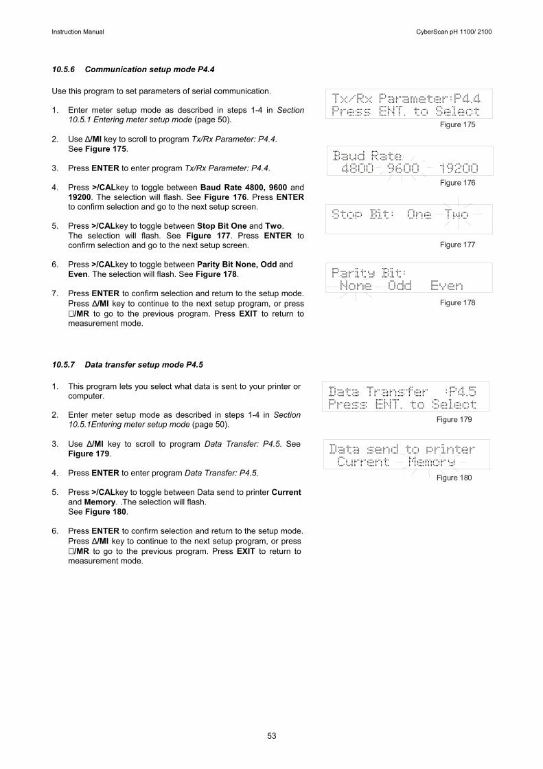
Instruction Manual CyberScan pH 1100/ 2100
53
10.5.6 Communication setup mode P4.4 Use this program to set parameters of serial communication. 1. Enter meter setup mode as described in steps 1-4 in Section
10.5.1 Entering meter setup mode (page 50). 2. Use ∆/MI key to scroll to program Tx/Rx Parameter: P4.4.
See Figure 175. 3. Press ENTER to enter program Tx/Rx Parameter: P4.4. 4. Press >/CALkey to toggle between Baud Rate 4800, 9600 and
19200. The selection will flash. See Figure 176. Press ENTER to confirm selection and go to the next setup screen.
5. Press >/CALkey to toggle between Stop Bit One and Two.
The selection will flash. See Figure 177. Press ENTER to confirm selection and go to the next setup screen.
6. Press >/CALkey to toggle between Parity Bit None, Odd and
Even. The selection will flash. See Figure 178. 7. Press ENTER to confirm selection and return to the setup mode.
Press ∆/MI key to continue to the next setup program, or press ∇ /MR to go to the previous program. Press EXIT to return to measurement mode.
10.5.7 Data transfer setup mode P4.5 1. This program lets you select what data is sent to your printer or
computer. 2. Enter meter setup mode as described in steps 1-4 in Section
10.5.1Entering meter setup mode (page 50). 3. Use ∆/MI key to scroll to program Data Transfer: P4.5. See
Figure 179. 4. Press ENTER to enter program Data Transfer: P4.5. 5. Press >/CALkey to toggle between Data send to printer Current
and Memory. .The selection will flash. See Figure 180.
6. Press ENTER to confirm selection and return to the setup mode.
Press ∆/MI key to continue to the next setup program, or press ∇ /MR to go to the previous program. Press EXIT to return to measurement mode.
Stop Bit: One Two
Baud Rate4800 9600 19200
Tx/Rx Parameter:P4.4Press ENT. to Select
Parity Bit:None Odd Even
Figure 175
Figure 176
Figure 177
Figure 178
Data send to printerCurrent Memory
Data Transfer :P4.5Press ENT. to Select
Figure 179
Figure 180
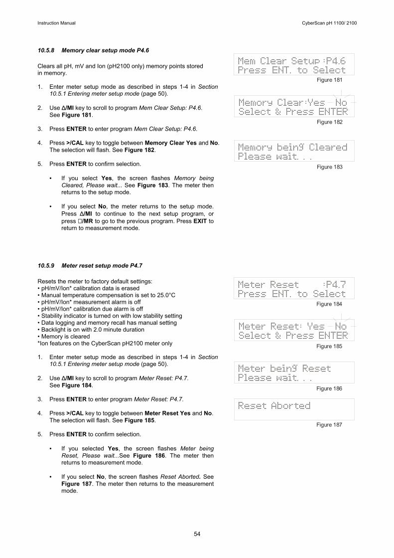
Instruction Manual CyberScan pH 1100/ 2100
54
10.5.8 Memory clear setup mode P4.6 Clears all pH, mV and Ion (pH2100 only) memory points stored in memory. 1. Enter meter setup mode as described in steps 1-4 in Section
10.5.1 Entering meter setup mode (page 50). 2. Use ∆/MI key to scroll to program Mem Clear Setup: P4.6.
See Figure 181. 3. Press ENTER to enter program Mem Clear Setup: P4.6. 4. Press >/CAL key to toggle between Memory Clear Yes and No.
The selection will flash. See Figure 182. 5. Press ENTER to confirm selection.
• If you select Yes, the screen flashes Memory being
Cleared, Please wait... See Figure 183. The meter then returns to the setup mode.
• If you select No, the meter returns to the setup mode.
Press ∆/MI to continue to the next setup program, or press ∇ /MR to go to the previous program. Press EXIT to return to measurement mode.
10.5.9 Meter reset setup mode P4.7 Resets the meter to factory default settings: • pH/mV/Ion* calibration data is erased • Manual temperature compensation is set to 25.0°C • pH/mV/Ion* measurement alarm is off • pH/mV/Ion* calibration due alarm is off • Stability indicator is turned on with low stability setting • Data logging and memory recall has manual setting • Backlight is on with 2.0 minute duration • Memory is cleared *Ion features on the CyberScan pH2100 meter only 1. Enter meter setup mode as described in steps 1-4 in Section
10.5.1 Entering meter setup mode (page 50). 2. Use ∆/MI key to scroll to program Meter Reset: P4.7.
See Figure 184. 3. Press ENTER to enter program Meter Reset: P4.7. 4. Press >/CAL key to toggle between Meter Reset Yes and No.
The selection will flash. See Figure 185. 5. Press ENTER to confirm selection.
• If you selected Yes, the screen flashes Meter being Reset, Please wait...See Figure 186. The meter then returns to measurement mode.
• If you select No, the screen flashes Reset Aborted. See
Figure 187. The meter then returns to the measurement mode.
Memory being ClearedPlease wait. . .
Memory Clear:Yes NoSelect & Press ENTER
Mem Clear Setup :P4.6Press ENT. to Select
Figure 181
Figure 182
Figure 183
Meter being ResetPlease wait. . .
Meter Reset: Yes NoSelect & Press ENTER
Meter Reset :P4.7Press ENT. to Select
Figure 184
Figure 185
Figure 186
Figure 187
Reset Aborted

Instruction Manual CyberScan pH 1100/ 2100
55
11 ELECTRODE CARE 11.1 Electrode Activation DO NOT touch or rub the glass bulb. If you follow the storage and maintenance procedure, you can use your electrode immediately. If the electrode responds sluggishly or drifts, the bulb may be dehydrated. Immerse the electrode in an ideal storage solution such as electrode storage solution or pH 4 buffer solution for 1-2 hours to hydrate it. See Storing pH/ORP electrodes below. If this procedure does not hydrate the electrode, reactivate or replace it. Use 2 or 3 point calibration to test your electrode performance. If you do not get good readings, use a different pH electrode to confirm the meter is working properly. If the results are still not satisfactory, consult your distributor/dealer. 11.2 Electrode Maintenance pH electrodes are susceptible to dirt, dehydration and contamination. Clean them regularly depending on the extent and condition of use. 11.3 Storing pH/ORP electrodes For best results, always keep the bulb wet, preferably in pH storage solution. Other pH buffers or tap water are also acceptable. Do not store in de-ionized water. Eutech Instruments/ Oakton Instruments offers a complete range of electrode storage and cleaning solutions. After Use 1. After each series of measurements, wash the electrode and reference junction in de-ionized water. 2. If using a refillable electrode, close the refilling hole by placing its rubber sleeve or stopper plug into its position. 3. Store the electrode as mentioned above. Electrode Cleaning Electrodes that are mechanically intact can often be restored to normal performance by one or a combination of the following options. Some suggestions for: a. Salt deposits which are normal on all electrodes Dissolve the deposit by immersing the electrode in tap water for 10 to 15 minutes. Thoroughly rinse with de-ionized water. b. General dirt and protein coatings Soak the electrode for several hours in the general-purpose electrode cleaning solutions. Rinse in de-ionized or tap water. c. Oil/Grease Films Wash the electrode pH bulb in a little dish washing detergent and water. Rinse the electrode tip with de-ionized water. d. Clogged reference junction. Heat a dilute 1% KCl solution or pH 4.01 buffer solution to 60-80°C. Place the sensing portion of the pH electrode into the heated KCl solution for approximately 30 minutes. Allow the electrode to cool while immersed in some unheated KCl solution or pH 4.01 buffer solution. Rinse with deionized water.
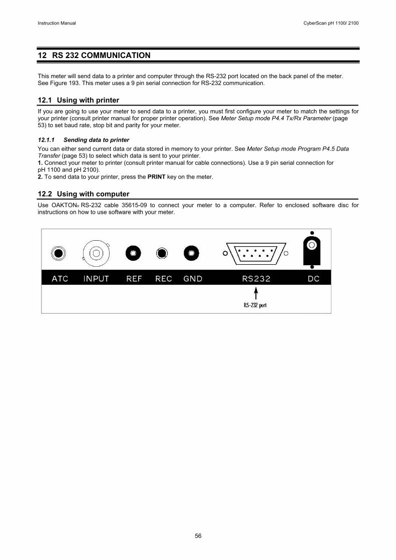
Instruction Manual CyberScan pH 1100/ 2100
56
12 RS 232 COMMUNICATION This meter will send data to a printer and computer through the RS-232 port located on the back panel of the meter. See Figure 193. This meter uses a 9 pin serial connection for RS-232 communication. 12.1 Using with printer If you are going to use your meter to send data to a printer, you must first configure your meter to match the settings for your printer (consult printer manual for proper printer operation). See Meter Setup mode P4.4 Tx/Rx Parameter (page 53) to set baud rate, stop bit and parity for your meter. 12.1.1 Sending data to printer You can either send current data or data stored in memory to your printer. See Meter Setup mode Program P4.5 Data Transfer (page 53) to select which data is sent to your printer. 1. Connect your meter to printer (consult printer manual for cable connections). Use a 9 pin serial connection for pH 1100 and pH 2100). 2. To send data to your printer, press the PRINT key on the meter. 12.2 Using with computer Use OAKTON® RS-232 cable 35615-09 to connect your meter to a computer. Refer to enclosed software disc for instructions on how to use software with your meter.
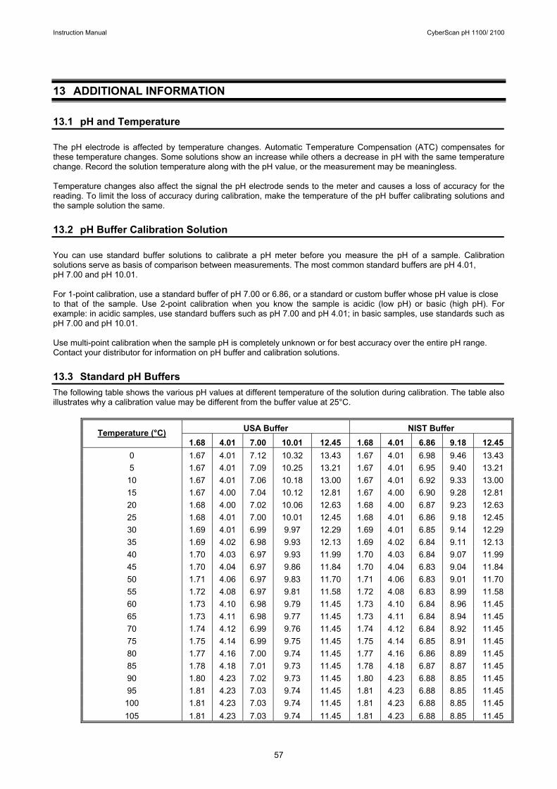
Instruction Manual CyberScan pH 1100/ 2100
57
13 ADDITIONAL INFORMATION 13.1 pH and Temperature The pH electrode is affected by temperature changes. Automatic Temperature Compensation (ATC) compensates for these temperature changes. Some solutions show an increase while others a decrease in pH with the same temperature change. Record the solution temperature along with the pH value, or the measurement may be meaningless. Temperature changes also affect the signal the pH electrode sends to the meter and causes a loss of accuracy for the reading. To limit the loss of accuracy during calibration, make the temperature of the pH buffer calibrating solutions and the sample solution the same. 13.2 pH Buffer Calibration Solution You can use standard buffer solutions to calibrate a pH meter before you measure the pH of a sample. Calibration solutions serve as basis of comparison between measurements. The most common standard buffers are pH 4.01, pH 7.00 and pH 10.01. For 1-point calibration, use a standard buffer of pH 7.00 or 6.86, or a standard or custom buffer whose pH value is close to that of the sample. Use 2-point calibration when you know the sample is acidic (low pH) or basic (high pH). For example: in acidic samples, use standard buffers such as pH 7.00 and pH 4.01; in basic samples, use standards such as pH 7.00 and pH 10.01. Use multi-point calibration when the sample pH is completely unknown or for best accuracy over the entire pH range. Contact your distributor for information on pH buffer and calibration solutions. 13.3 Standard pH Buffers The following table shows the various pH values at different temperature of the solution during calibration. The table also illustrates why a calibration value may be different from the buffer value at 25°C.
USA Buffer NIST Buffer Temperature (°C) 1.68 4.01 7.00 10.01 12.45 1.68 4.01 6.86 9.18 12.45
0 1.67 4.01 7.12 10.32 13.43 1.67 4.01 6.98 9.46 13.43 5 1.67 4.01 7.09 10.25 13.21 1.67 4.01 6.95 9.40 13.21
10 1.67 4.01 7.06 10.18 13.00 1.67 4.01 6.92 9.33 13.00 15 1.67 4.00 7.04 10.12 12.81 1.67 4.00 6.90 9.28 12.81 20 1.68 4.00 7.02 10.06 12.63 1.68 4.00 6.87 9.23 12.63 25 1.68 4.01 7.00 10.01 12.45 1.68 4.01 6.86 9.18 12.45 30 1.69 4.01 6.99 9.97 12.29 1.69 4.01 6.85 9.14 12.29 35 1.69 4.02 6.98 9.93 12.13 1.69 4.02 6.84 9.11 12.13 40 1.70 4.03 6.97 9.93 11.99 1.70 4.03 6.84 9.07 11.99 45 1.70 4.04 6.97 9.86 11.84 1.70 4.04 6.83 9.04 11.84 50 1.71 4.06 6.97 9.83 11.70 1.71 4.06 6.83 9.01 11.70 55 1.72 4.08 6.97 9.81 11.58 1.72 4.08 6.83 8.99 11.58 60 1.73 4.10 6.98 9.79 11.45 1.73 4.10 6.84 8.96 11.45 65 1.73 4.11 6.98 9.77 11.45 1.73 4.11 6.84 8.94 11.45 70 1.74 4.12 6.99 9.76 11.45 1.74 4.12 6.84 8.92 11.45 75 1.75 4.14 6.99 9.75 11.45 1.75 4.14 6.85 8.91 11.45 80 1.77 4.16 7.00 9.74 11.45 1.77 4.16 6.86 8.89 11.45 85 1.78 4.18 7.01 9.73 11.45 1.78 4.18 6.87 8.87 11.45 90 1.80 4.23 7.02 9.73 11.45 1.80 4.23 6.88 8.85 11.45 95 1.81 4.23 7.03 9.74 11.45 1.81 4.23 6.88 8.85 11.45 100 1.81 4.23 7.03 9.74 11.45 1.81 4.23 6.88 8.85 11.45 105 1.81 4.23 7.03 9.74 11.45 1.81 4.23 6.88 8.85 11.45
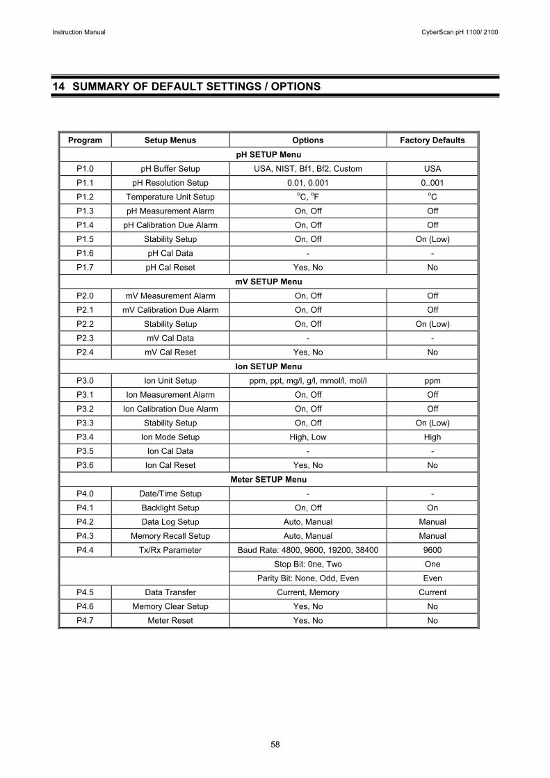
Instruction Manual CyberScan pH 1100/ 2100
58
14 SUMMARY OF DEFAULT SETTINGS / OPTIONS
Program Setup Menus Options Factory Defaults
pH SETUP Menu P1.0 pH Buffer Setup USA, NIST, Bf1, Bf2, Custom USA
P1.1 pH Resolution Setup 0.01, 0.001 0..001
P1.2 Temperature Unit Setup oC, oF oC
P1.3 pH Measurement Alarm On, Off Off
P1.4 pH Calibration Due Alarm On, Off Off
P1.5 Stability Setup On, Off On (Low)
P1.6 pH Cal Data - -
P1.7 pH Cal Reset Yes, No No
mV SETUP Menu
P2.0 mV Measurement Alarm On, Off Off
P2.1 mV Calibration Due Alarm On, Off Off
P2.2 Stability Setup On, Off On (Low)
P2.3 mV Cal Data - -
P2.4 mV Cal Reset Yes, No No
Ion SETUP Menu
P3.0 Ion Unit Setup ppm, ppt, mg/l, g/l, mmol/l, mol/l ppm
P3.1 Ion Measurement Alarm On, Off Off
P3.2 Ion Calibration Due Alarm On, Off Off
P3.3 Stability Setup On, Off On (Low)
P3.4 Ion Mode Setup High, Low High
P3.5 Ion Cal Data - -
P3.6 Ion Cal Reset Yes, No No
Meter SETUP Menu
P4.0 Date/Time Setup - -
P4.1 Backlight Setup On, Off On
P4.2 Data Log Setup Auto, Manual Manual
P4.3 Memory Recall Setup Auto, Manual Manual
P4.4 Tx/Rx Parameter Baud Rate: 4800, 9600, 19200, 38400 9600
Stop Bit: 0ne, Two One
Parity Bit: None, Odd, Even Even
P4.5 Data Transfer Current, Memory Current
P4.6 Memory Clear Setup Yes, No No
P4.7 Meter Reset Yes, No No
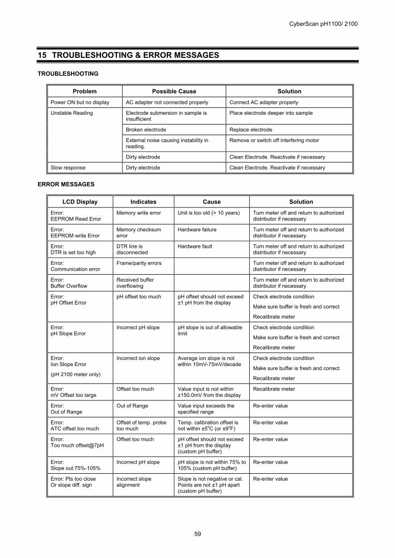
CyberScan pH1100/ 2100
59
15 TROUBLESHOOTING & ERROR MESSAGES TROUBLESHOOTING
Problem Possible Cause Solution
Power ON but no display AC adapter not connected properly Connect AC adapter properly
Unstable Reading Electrode submersion in sample is insufficient
Place electrode deeper into sample
Broken electrode Replace electrode
External noise causing instability in reading.
Remove or switch off interfering motor
Dirty electrode Clean Electrode. Reactivate if necessary
Slow response Dirty electrode Clean Electrode. Reactivate if necessary
ERROR MESSAGES
LCD Display Indicates Cause Solution
Error: EEPROM Read Error
Memory write error Unit is too old (> 10 years) Turn meter off and return to authorized distributor if necessary
Error: EEPROM write Error
Memory checksum error
Hardware failure Turn meter off and return to authorized distributor if necessary
Error: DTR is set too high
DTR line is disconnected
Hardware fault Turn meter off and return to authorized distributor if necessary
Error: Communication error
Frame/parity errors Turn meter off and return to authorized distributor if necessary
Error: Buffer Overflow
Received buffer overflowing
Turn meter off and return to authorized distributor if necessary
Error: pH Offset Error
pH offset too much pH offset should not exceed ±1 pH from the display
Check electrode condition
Make sure buffer is fresh and correct
Recalibrate meter
Error: pH Slope Error
Incorrect pH slope pH slope is out of allowable limit
Check electrode condition
Make sure buffer is fresh and correct
Recalibrate meter
Error: Ion Slope Error
(pH 2100 meter only)
Incorrect ion slope Average ion slope is not within 10mV-75mV/decade
Check electrode condition
Make sure buffer is fresh and correct
Recalibrate meter
Error: mV Offset too large
Offset too much Value input is not within ±150.0mV from the display
Recalibrate meter
Error: Out of Range
Out of Range Value input exceeds the specified range
Re-enter value
Error: ATC offset too much
Offset of temp. probe too much
Temp. calibration offset is not within ±5oC (or ±9oF)
Re-enter value
Error: Too much offset@7pH
Offset too much pH offset should not exceed ±1 pH from the display (custom pH buffer)
Re-enter value
Error: Slope out:75%-105%
Incorrect pH slope pH slope is not within 75% to 105% (custom pH buffer)
Re-enter value
Error: Pts too close Or slope diff. sign
Incorrect slope alignment
Slope is not negative or cal. Points are not ±1 pH apart (custom pH buffer)
Re-enter value
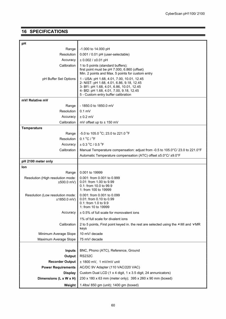
CyberScan pH1100/ 2100
60
16 SPECIFICATIONS pH
Range -1.000 to 14.000 pH Resolution 0.001 / 0.01 pH (user-selectable)
Accuracy ± 0.002 / ±0.01 pH Calibration 1 to 5 points (standard buffers);
first point must be pH 7.000, 6.860 (offset) Min. 2 points and Max. 5 points for custom entry
pH Buffer Set Options 1 - USA: pH 1.68, 4.01, 7.00, 10.01, 12.45 2- NIST: pH 1.68, 4.01, 6.86, 9.18, 12.45 3- Bf1: pH 1.68, 4.01, 6.86, 10.01, 12.45 4- Bf2: pH 1.68, 4.01, 7.00, 9.18, 12.45 5 - Custom entry buffer calibration
mV/ Relative mV Range - 1850.0 to 1850.0 mV
Resolution 0.1 mV Accuracy ± 0.2 mV
Calibration mV offset up to ± 150 mV
Temperature Range -5.0 to 105.0 oC; 23.0 to 221.0 oF
Resolution 0.1 oC / oF Accuracy ± 0.3 oC / 0.5 oF
Calibration Manual Temperature compensation: adjust from -0.5 to 105.0°C/ 23.0 to 221.0°F Automatic Temperature compensation (ATC) offset ±5.0°C/ ±9.0°F
pH 2100 meter only
Ion Range 0.001 to 19999
Resolution (High resolution mode: ±500.0 mV)
0.001: from 0.001 to 0.999 0.01: from 1.00 to 9.99 0.1: from 10.0 to 99.9 1: from 100 to 19999
Resolution (Low resolution mode: ±1850.0 mV)
0.001: from 0.001 to 0.099 0.01: from 0.10 to 0.99 0.1: from 1.0 to 9.9 1: from 10 to 19999
Accuracy ± 0.5% of full scale for monovalent ions
1% of full scale for divalent ions Calibration 2 to 5 points, First point keyed in. the rest are selected using the MI and MR
keys Minimum Average Slope 10 mV/ decade Maximum Average Slope 75 mV/ decade
Inputs BNC, Phono (ATC), Reference, Ground
Output RS232C Recorder Output ± 1800 mV, 1 mV/mV unit
Power Requirements AC/DC 9V Adapter (110 VAC/220 VAC) Display Custom Dual LCD (1 x 4 digit, 1 x 3.5 digit, 24 annunicators)
Dimensions (L x W x H) 230 x 180 x 63 mm (meter only); 395 x 260 x 90 mm (boxed)
Weight 1.4lbs/ 850 gm (unit); 1400 gm (boxed)
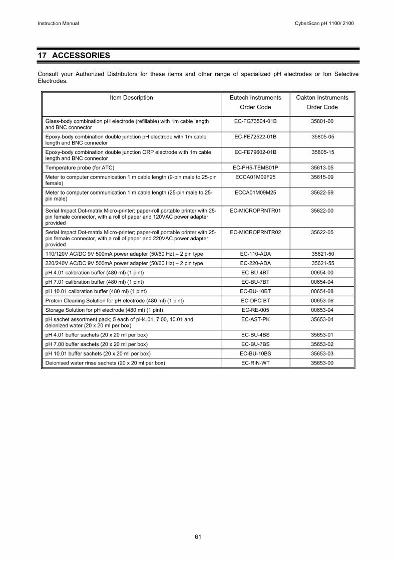
Instruction Manual CyberScan pH 1100/ 2100
61
17 ACCESSORIES Consult your Authorized Distributors for these items and other range of specialized pH electrodes or Ion Selective Electrodes.
Item Description Eutech Instruments Order Code
Oakton Instruments Order Code
Glass-body combination pH electrode (refillable) with 1m cable length and BNC connector
EC-FG73504-01B 35801-00
Epoxy-body combination double junction pH electrode with 1m cable length and BNC connector
EC-FE72522-01B 35805-05
Epoxy-body combination double junction ORP electrode with 1m cable length and BNC connector
EC-FE79602-01B 35805-15
Temperature probe (for ATC) EC-PH5-TEMB01P 35613-05
Meter to computer communication 1 m cable length (9-pin male to 25-pin female)
ECCA01M09F25 35615-09
Meter to computer communication 1 m cable length (25-pin male to 25-pin male)
ECCA01M09M25 35622-59
Serial Impact Dot-matrix Micro-printer; paper-roll portable printer with 25-pin female connector, with a roll of paper and 120VAC power adapter provided
EC-MICROPRNTR01 35622-00
Serial Impact Dot-matrix Micro-printer; paper-roll portable printer with 25-pin female connector, with a roll of paper and 220VAC power adapter provided
EC-MICROPRNTR02 35622-05
110/120V AC/DC 9V 500mA power adapter (50/60 Hz) – 2 pin type EC-110-ADA 35621-50
220/240V AC/DC 9V 500mA power adapter (50/60 Hz) – 2 pin type EC-220-ADA 35621-55
pH 4.01 calibration buffer (480 ml) (1 pint) EC-BU-4BT 00654-00
pH 7.01 calibration buffer (480 ml) (1 pint) EC-BU-7BT 00654-04
pH 10.01 calibration buffer (480 ml) (1 pint) EC-BU-10BT 00654-08
Protein Cleaning Solution for pH electrode (480 ml) (1 pint) EC-DPC-BT 00653-06
Storage Solution for pH electrode (480 ml) (1 pint) EC-RE-005 00653-04
pH sachet assortment pack; 5 each of pH4.01, 7.00, 10.01 and deionized water (20 x 20 ml per box)
EC-AST-PK 35653-04
pH 4.01 buffer sachets (20 x 20 ml per box) EC-BU-4BS 35653-01
pH 7.00 buffer sachets (20 x 20 ml per box) EC-BU-7BS 35653-02
pH 10.01 buffer sachets (20 x 20 ml per box) EC-BU-10BS 35653-03
Deionised water rinse sachets (20 x 20 ml per box) EC-RIN-WT 35653-00
Instruction Manual CyberScan pH 1100/ 2100
62
18 WARRANTY Eutech Instruments/ Oakton Instruments supplies this bench meter with a 3-year warranty and 6-month warranty for against manufacturing defects from the date of purchase. If repair or adjustment is necessary and has not been the result of abuse or misuse within the warranty period, please return, freight prepaid, and correction will be made without charge. Out of warranty items will be repaired on a charge basis. Exclusions to the Warranty The warranty shall not apply to defects resulting from: • Improper or inadequate maintenance by customer; • Unauthorized modification or misuse; • Operation outside of the environmental specifications of the products. Return of Items Authorization must be obtained from your Authorized Distributor or Customer Service Dept. before returning items for any reason. When applying for authorization, please include data regarding reason the items are to be returned. Packing the item for repair should be done using the original packaging or material, with information about any fault identified. Shipment damage as a result of inadequate packaging is your or your distributor’s responsibility, whoever applicable. Note: Eutech Instruments/ Oakton Instruments reserves the rights to make improvements in design,
construction, and appearance of products without notice.

NOTES
For more information on Eutech Instruments/ Oakton Instruments’ products, contact your nearest distributor or visit our website listed below:
Oakton Instruments P.O Box 5136, Vernon Hills, IL60061, USA Fax: (1) 847-247-2984 www.4oakton.com www.oaktoninstruments.com
Eutech Instruments Pte Ltd Blk 55, Ayer Rajah Crescent, #04-16/24 Singapore 139949 Tel: (65) 6778 6876 Fax: (65) 6773 0836 E-mail: [email protected] Web-site: www.eutechinst.com
Distributed by:
Top Related