


Languages
Pages
Legal

InstallationOperationMaintenance
Split System Evaporator Unit - 5 to 50 TonFan and Coil ModulesOnix Split System - CXPA
50/60 Hz
SSC-SVN001F-ENNovember 2016
SAFETYWARNINGOnly qualified personnel should install and service the equipment. The installation, starting up, andservicing of heating, ventilating, and air-conditioning equipment can be hazardous and requires specificknowledge and training. Improperly installed, adjusted or altered equipment by an unqualified personcould result in death or serious injury. When working on the equipment, observe all precautions in theliterature and on the tags, stickers, and labels that are attached to the equipment.
2 SSC-SVN001F-EN
Important Notice
Refrigerant Emission ControlGas conservation and emissionreduction should be accomplished byadhering to operational and serviceprocedures recommended by Trane,with special attention to the following:
The refrigerant used in any type of ACequipment must be always recoveredand/or recycled for reuse, reclaimed orcompletely destroyed after beingremoved from the unit. Never releasethe refrigerant to the atmosphere.
Always consider the possibility ofrecycling or reprocessing the refrigerantbefore starting the reclaim process byany method.
The ARI 700 Standard coversquestions about recovered refrigerantand acceptable quality.
Use only approved and safe cylinders.All applicable safety and shippingstandards must be met during thetransportation of refrigerant containers.
Recycling equipment should be used tominimize emissions during the transferof refrigerant gas. Always use methodsthat generate the lowest possiblevacuum during the recovery andcondensation of refrigerant into thecylinder.
Literature Change HistoryThis new manual describes theinstallation, operation and maintenanceprocedures for the new CXPAevaporator units of the Trane Onix SplitSystem.
Important:Trane do Brasil has a policy of continuous product development and reserves the right to change design andspecifications without notice. Only qualified technicians or technicians authorized by Trane should perform theinstallation and servicing of equipment referred to in this publication. Failure to comply with and/or adhere to theprocedures in this manual may void the product warranty.
IMPORTANT:Dimensional measuring units on thiscatalog are on milimitres (mm).(Exept for those locally referencied).
SSC-SVN001F-EN 3
Table of Contents
Important Notice 2
General Data 4
Unit Inspection 6
Transport and Handling 7
Installation Procedures 8
Refrigeration Piping (Interconnection) 9
Operation 10
Maintenance Procedures 12
Periodical Preventive Maintenance 14
Motor Electrical Data 15
Wiring Diagram 18
Dimensional Data 19
Conversion Table 38
4 SSC-SVN001F-EN
GeneralData 050 to 500
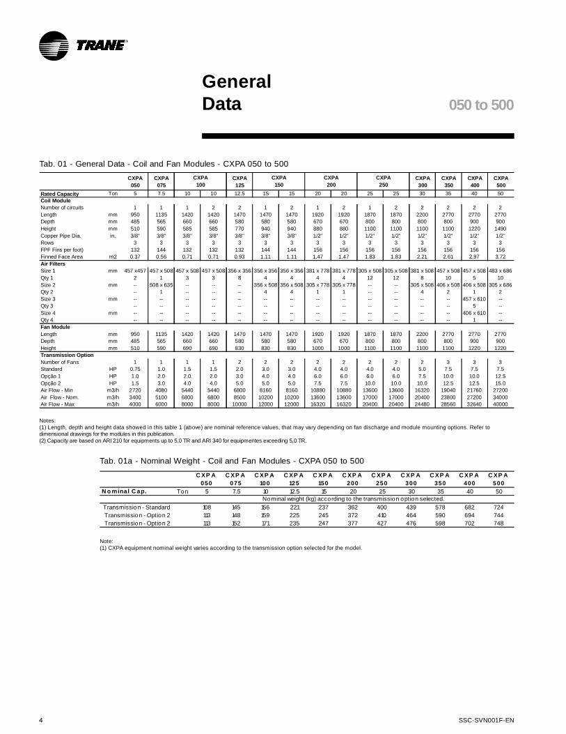
Tab. 01 - General Data - Coil and Fan Modules - CXPA 050 to 500
C XP A
050
C XP A
075
C XP A
100
C XP A
125
C XP A
150
C XP A
200
C XP A
250
C XP A
300
C XP A
350
C XP A
400
C XP A
500
N o minal C ap. Ton 5 7.5 10 12.5 15 20 25 30 35 40 50
Transmission - Standard 108 145 156 221 237 362 400 439 578 682 724
Transmission - Option 2 113 148 159 225 245 372 410 464 590 694 744
Transmission - Option 2 113 152 171 235 247 377 427 476 598 702 748
Nominal weight (kg) according to the transmission option selected.
Tab. 01a - Nominal Weight - Coil and Fan Modules - CXPA 050 to 500
Note:(1) CXPA equipment nominal weight varies according to the transmission option selected for the model.
Notes:(1) Length, depth and height data showed in this table 1 (above) are nominal reference values, that may vary depending on fan discharge and module mounting options. Refer todimensional drawings for the modules in this publication.(2) Capacity are based on ARI 210 for equipments up to 5,0 TR and ARI 340 for equipmentes exceeding 5,0 TR.
CXPA
050
CXPA
075
CXPA
125
CXPA
300
CXPA
350
CXPA
400
CXPA
500
Rated Capacity Ton 5 7.5 10 10 12.5 15 15 20 20 25 25 30 35 40 50
Number of circuits 1 1 1 2 2 1 2 1 2 1 2 2 2 2 2
Length mm 950 1135 1420 1420 1470 1470 1470 1920 1920 1870 1870 2200 2770 2770 2770
Depth mm 485 565 660 660 580 580 580 670 670 800 800 800 800 900 900
Height mm 510 590 585 585 770 940 940 880 880 1100 1100 1100 1100 1220 1490
Copper Pipe Dia. in. 3/8" 3/8" 3/8" 3/8" 3/8" 3/8" 3/8" 1/2" 1/2" 1/2" 1/2" 1/2" 1/2" 1/2" 1/2"
Rows 3 3 3 3 3 3 3 3 3 3 3 3 3 3 3
FPF Fins per foot) 132 144 132 132 132 144 144 156 156 156 156 156 156 156 156
Finned Face Area m2 0.37 0.56 0.71 0.71 0.93 1.11 1.11 1.47 1.47 1.83 1.83 2.21 2.61 2.97 3.72
Size 1 mm 457 x457 457 x 508 457 x 508 457 x 508 356 x 356 356 x 356 356 x 356 381 x 778 381 x 778 305 x 508 305 x 508 381 x 508 457 x 508 457 x 508 483 x 686
Qty 1 2 1 3 3 8 4 4 4 4 12 12 8 10 5 10
Size 2 mm -- 508 x 635 -- -- -- 356 x 508 356 x 508 305 x 778 305 x 778 -- -- 305 x 508 406 x 508 406 x 508 305 x 686
Qty 2 -- 1 -- -- -- 4 4 1 1 -- -- 4 2 1 2
Size 3 mm -- -- -- -- -- -- -- -- -- -- -- -- -- 457 x 610 --
Qty 3 -- -- -- -- -- -- -- -- -- -- -- -- -- 5 --
Size 4 mm -- -- -- -- -- -- -- -- -- -- -- -- -- 406 x 610 --
Qty 4 -- -- -- -- -- -- -- -- -- -- -- -- -- 1 --
Length mm 950 1135 1420 1420 1470 1470 1470 1920 1920 1870 1870 2200 2770 2770 2770
Depth mm 485 565 660 660 580 580 580 670 670 800 800 800 800 900 900
Height mm 510 590 690 690 830 830 830 1000 1000 1100 1100 1100 1100 1220 1220
Number of Fans 1 1 1 1 2 2 2 2 2 2 2 2 3 3 3
Standard HP 0.75 1.0 1.5 1.5 2.0 3.0 3.0 4.0 4.0 4.0 4.0 5.0 7.5 7.5 7.5
Opção 1 HP 1.0 2.0 2.0 2.0 3.0 4.0 4.0 6.0 6.0 6.0 6.0 7.5 10.0 10.0 12.5
Opção 2 HP 1.5 3.0 4.0 4.0 5.0 5.0 5.0 7.5 7.5 10.0 10.0 10.0 12.5 12.5 15.0
Air Flow - Min m3/h 2720 4080 5440 5440 6800 8160 8160 10880 10880 13600 13600 16320 19040 21760 27200
Air Flow - Nom. m3/h 3400 5100 6800 6800 8500 10200 10200 13600 13600 17000 17000 20400 23800 27200 34000
Air Flow - Max m3/h 4000 6000 8000 8000 10000 12000 12000 16320 16320 20400 20400 24480 28560 32640 40000
CXPA
100
CXPA
150
CXPA
200
CXPA
250
Coil Module
Air Filters
Fan Module
Transmission Option

SSC-SVN001F-EN 5
Tab. 02 - General Data - Condensing Units TRAE - 050 to 300
GeneralData TRAE/TRCE
Note:(1) RLA = Rated Amps - 220V / 60 Hz. (2) FLA = Full Load Amps - 220V / 60 HZ (3) Voltagem variation: +/- 10%
Mod el 0 5 0 0 7 5
Nom in al Cap. Ton 5 7,5
Widt h m m 993 1217
Dep t h m m 560 560
Heigh t m m 1393 1494
Typ e Scro ll Scro ll
Rows 4 4
FPF (Fin pe r Fee t) f t 144 144
Fin Side Area m 20,55 0,83
Quan t it y 1 1
Mot o r CV 1 ,5 3
N° Fase 3 3
Mot o r Ro t at io n / No o f Po le s RPM 1700 / 4 1710 / 4
Air Flo w m 3/h 5500 8250
Equ ip m e n t We ig t h kg 184 210 305 310 400 400
Dim e n sio n s
Con d e ns in g Fan
Con d e ns in g Co il
Com p r esso r
1720 / 4 1720 / 4 1730 / 4
9 950 13770
352
15750
1 1 1
4 4 5
3 3 3
4 4 4
144 144 144
0,99 1,3 9 1,72
Scro ll Scro ll Sc ro ll
C1: 1/7,51/10
C2: 1/51/15 2/7,5
1 545 1620 1 849
1 491 1712 1 712
560 560 560
1 00 1 25 1 50
10 12,5 15
Qty/To n 2/51 /7,51/5Ton
Tab. 03 - Dados gerais unidade condensadora TRCE050 a 150 (60Hz)
M o del 50 75 300
Nominal Cap. Ton 5 7,5 30
D imens io ns
Width mm 920 930 1850
Depth mm 420 620 1060
Height mm 818 920 1600
C o mpresso r
Type Scroll Scroll Scro ll
Qty. Ton 1 1 1 2 1 2 1 2 2
Rows 2 2 2 2 2 2 3
FPF (Fins per foot) 228 216 216 216 144
Fin Side Area m2 0,8 1,01 1,67 1,67 4,5
C o ndensing F an
Quantity 1 1 1 1 2
Propeller diameter mm 22" 26" 30" 30" 30"
Air Flow m3/h 7234 9180 11900 11900 32300
P ipe D iameters
Number of Circuits 1 1 1 2 1 2 1 2 1 2 2
Equipment Weight kg 108 127 198 196 335 275 355 359 360 368 610
1021
Scroll
800
1275
100
10
1140
800
12,5
C o ndensing C o il
Scroll Scroll Scroll
2
Scroll
1or 2
15 20 25
1350 1590 1067 1067
1096
200150125 250
1452
1096
1452
800
1275
2 2 2
204216 216 204
2,242,24
1
30"
2
26"
1
35"
1
35"
3,332,97
15300
2
18360
1/2"7/8"
3060023800
5/8" 7/8"11/8"5/8"7/8"1/2"5/8" 1/2"1/2"1/2"in.Liquid Line
2 1/8"13/8"15/8"11/8"15/8"C1: 11/8"
C2: 7/8"7/8"Suction Line 15/8"
227
13/8"11/8"7/8"in. 13/8"

6 SSC-SVN001F-EN
Unit InspectionAfter the unit is delivered at the job site:- Verify that the nameplate data matchesthe data on the sales order and bill oflading (including electrical data).- Verify that the power supply matchesthe unit nameplate specifications.- Inspect the unit carefully for anyshipping damage.If any damage or material shortage isfound it must be reported immediatelyto the carrier. Specify the type andextent of the damage on the carrier'sdelivery receipt before signing.- Notify Trane do Brasil and/or thecontractor about the damages andactions to repair the unit. Do notattempt to repair the unit until thedamages are inspected.
StorageIf it is not possible to install the unit afterdelivery, it should be stored in a safelocation, protected from the weatherand other damages. Improperequipment storage or handling will voidthe equipment warranty.
Unit Inspection
Instructions for proper installationPlease consider the following itemsrequired for proper installation beforeplacing the unit at the mountinglocation:- The mechanical room should beprovided with proper lighting forservicing and maintenance.- Make certain the floor or foundationis level, solid, and sufficient to supportthe unit and accessory weights. Levelor repair the floor before positioning theunit.- Provide the units with rubber pads orvibration isolators.- Install the hydraulic componentsrequired to drain the water from thecondensate tray.- Allow minimum recommendedclearances for routine maintenanceand service (see page 20).- The same clearances should beobserved in case of several unitstogether or condensing units.- Provide electrical installation. Theunit has electrical inputs on both sides.- Provide enough clearance to accesspiping and remove covers.The power supply must comply withStandard NBR 5410, as well as localcodes and/or NEC.- The contractor should provide andinstall the refrigeration piping - both forthe liquid line and the suction line - inorder to interconnect evaporator andcondensing units.
General SafetyThe Trane equipment is designed forsafe and reliable operation, as longas units are operated according to theapplicable safety rules. The systemuses electrical and mechanical parts,as well as gas pressures, that mayinjury people or damage the equipmentif safety rules are not followed.Therefore, the installation, start-up andmaintenance of this equipment must beperformed only by qualified personnelor personnel approved by Trane doBrasil. Follow all safety standardsrelated to the task and warnings on unitlabels, and always use proper tools andequipment.
Hazard Identification
WARNING!!Warnings appear at appropriateintervals and sections throughoutthis manual to warn operatorsand service personnel about apotentially hazardous situationwhich MAY result in seriousinjury or equipment damage ifsafety rules are not met.
CAUTION:!
Cautions appear at appropriateintervals and sections throughoutthis manual to warn operatorsand service personnel about apotentially hazardous situationwhich may result in damage tothe equipment and/orenvironment.
SSC-SVN001F-EN 7
Transport andHandling
Handling and DisplacementInstructionsProceed as follows to transport andhandle the unit:
1. Check the manual or nameplate forthe actual equipment weight.
2. For all units, place lifting cables orchains under the skid. Other liftingmethods may cause serious injuries orequipment damage.
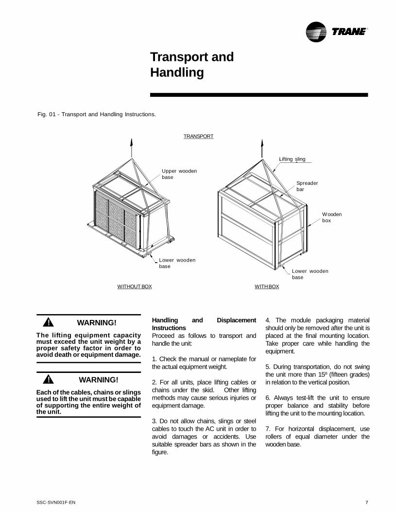
3. Do not allow chains, slings or steelcables to touch the AC unit in order toavoid damages or accidents. Usesuitable spreader bars as shown in thefigure.
4. The module packaging materialshould only be removed after the unit isplaced at the final mounting location.Take proper care while handling theequipment.
5. During transportation, do not swingthe unit more than 15º (fifteen grades)in relation to the vertical position.
6. Always test-lift the unit to ensureproper balance and stability beforelifting the unit to the mounting location.
7. For horizontal displacement, userollers of equal diameter under thewooden base.
Fig. 01 - Transport and Handling Instructions.
TRANSPORT
Upper woodenbase
Lower woodenbase
Lifting sling
Spreaderbar
Woodenbox
Lower woodenbase
WITHBOXWITHOUT BOX
WARNING!!
Each of the cables, chains or slingsused to lift the unit must be capableof supporting the entire weight ofthe unit.
WARNING!!
The lifting equipment capacitymust exceed the unit weight by aproper safety factor in order toavoid death or equipment damage.
8 SSC-SVN001F-EN
Installation ChecklistComplete this checklist after installingthe unit to verify that all recommendedinstallation procedures are completebefore unit start-up.
This checklist does not replace thedetailed instructions in the appropriatesections of this manual. Always readthe entire section carefully to becomefamiliar with the procedures.
ReceivingThe unit and parts have been
inspected to check for shippingdamages.
The unit has been checked forcontrol and material shortage.
The nameplate data has beenverified against the order data.
Unit LocationThe unit package has been
removed from the unit. Do not removethe skid until the unit is at its finallocation.
The unit location is appropriatefor the size of the unit and all air ducts,refrigeration pipings and electricalducts.
There are proper access andmaintenance clearances providedaround the unit.
Unit HandlingProceed according to
instructions on page 6 of this manual.
Unit InstallationThe unit is located at its final
position.The skid and screws have been
removed.The unit is properly installed and
the drain slope is correct.Rubber pads or isolators are
properly adjusted (if installed).Compressor pad screws have
been re-tightened.
Component ReviewFan and motor shafts are
parallel.Fan and motor sheaves are
aligned.The fan belt tension is correct.Rotors can be freely turned.Locking screws, bearing screws
and sheaves are tightened.Bearings do not oscillate when
turned.
Air DuctsThe unit return duct (if used) is
secured and at least 8 cm of flexibleduct or canvas are available.
The air supply duct must not bechanged or reduced, and its directionmust not be altered. The distance to theair supply discharge should be at leastthree times the duct diameter. Place atleast 8 cm of flexible duct or canvas.
InstallationProcedures
WARNING!!
Disconnect the power supply toavoid injuries or death caused byelectrical shock.
The main duct is connected toterminal units and there are no leaks.
All ducts comply with ABNTStandards.
Refrigerant PipingSiphons have been installed in
the suction line, if required.Pipings have been leak-tested.Refrigerant pipings are not
touching any other objects.
ControlsThe control thermostat is
properly installed in an area away fromlamp heat, warm or cold air flows, directsun light and not behind any doors.
Wiring DiagramsCheck the wiring diagram on the
internal cover of the electrical panel.Power is supplied to the AC unit
by disconnecting switches or circuitbreakers.
Verify that all electrical terminalsare re-tighten.
Check phase sequencing andunit connections.
SSC-SVN001F-EN 9
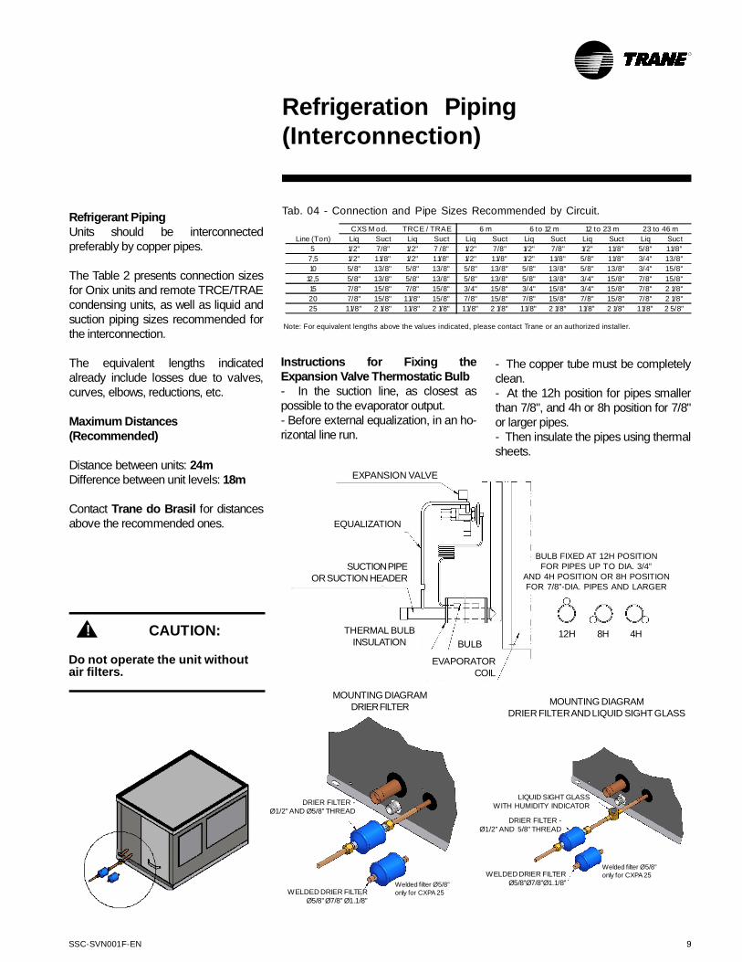
EXPANSION VALVE
EQUALIZATION
SUCTIONPIPEORSUCTION HEADER
THERMAL BULBINSULATION BULB
EVAPORATORCOIL
BULB FIXED AT 12H POSITIONFOR PIPES UP TO DIA. 3/4”
AND 4H POSITION OR 8H POSITIONFOR 7/8”-DIA. PIPES AND LARGER
12H 8H 4H
Refrigerant PipingUnits should be interconnectedpreferably by copper pipes.
The Table 2 presents connection sizesfor Onix units and remote TRCE/TRAEcondensing units, as well as liquid andsuction piping sizes recommended forthe interconnection.
The equivalent lengths indicatedalready include losses due to valves,curves, elbows, reductions, etc.
Maximum Distances(Recommended)
Distance between units: 24mDifference between unit levels: 18m
Contact Trane do Brasil for distancesabove the recommended ones.
Refrigeration Piping(Interconnection)
Instructions for Fixing theExpansion Valve Thermostatic Bulb- In the suction line, as closest aspossible to the evaporator output.- Before external equalization, in an ho-rizontal line run.
Tab. 04 - Connection and Pipe Sizes Recommended by Circuit.
Liq Suct Liq Suct Liq Suct Liq Suct Liq Suct Liq Suct
5 1/2" 7/8" 1/2" 7 /8" 1/2" 7/8" 1/2" 7/8" 1/2" 11/8" 5/8" 11/8"
7,5 1/2" 11/8" 1/2" 11/8" 1/2" 11/8" 1/2" 11/8" 5/8" 11/8" 3/4" 13/8"
10 5/8" 13/8" 5/8" 13/8" 5/8" 13/8" 5/8" 13/8" 5/8" 13/8" 3/4" 15/8"
12,5 5/8" 13/8" 5/8" 13/8" 5/8" 13/8" 5/8" 13/8" 3/4" 15/8" 7/8" 15/8"
15 7/8" 15/8" 7/8" 15/8" 3/4" 15/8" 3/4" 15/8" 3/4" 15/8" 7/8" 2 1/8"
20 7/8" 15/8" 11/8" 15/8" 7/8" 15/8" 7/8" 15/8" 7/8" 15/8" 7/8" 2 1/8"
25 11/8" 2 1/8" 11/8" 2 1/8" 11/8" 2 1/8" 11/8" 2 1/8" 11/8" 2 1/8" 11/8" 2 5/8"
TRCE / TRAECXS M o d.
Line (Ton)
6 m 6 to 12 m 12 to 23 m 23 to 46 m
Note: For equivalent lengths above the values indicated, please contact Trane or an authorized installer.
- The copper tube must be completelyclean.- At the 12h position for pipes smallerthan 7/8", and 4h or 8h position for 7/8"or larger pipes.- Then insulate the pipes using thermalsheets.
MOUNTING DIAGRAMDRIER FILTERANDLIQUID SIGHT GLASS
CAUTION:!
Do not operate the unit withoutair filters.
MOUNTING DIAGRAMDRIERFILTER
DRIER FILTER -Ø1/2” AND Ø5/8” THREAD
WELDED DRIER FILTERØ5/8” Ø7/8” Ø1.1/8”
Welded filter Ø5/8”only for CXPA 25
DRIER FILTER -Ø1/2” AND 5/8” THREAD
LIQUID SIGHT GLASSWITH HUMIDITY INDICATOR
WELDED DRIER FILTERØ5/8”Ø7/8”Ø1.1/8”
Welded filter Ø5/8”only for CXPA 25
10 SSC-SVN001F-EN
Operation
Specifically developed to keep the properpressure of the air-cooled condenserduring periods of low conditions ofexternal environment.
GeneralThe air-cooled condensers application foroperation during the whole year or duringlow temperatures periods requires somemeans of control to keep condensingpressures that assure a proper systemoperation. It is essential that the properpressure of the refrigerant liquid iscontrolled to:
1. Keep the liquid subcooling and avoidgas bubbles in the liquid line.
2. Provide an adequate pressure at theadmission side of the thermostatic valve
High Pressure Control Valve - HeadMaster Alco
to obtain a sufficient drop pressure bymeansof thevalvegate.
Without a proper condensing pressurecontrol, serious consequences like badcooling and components damage mayoccur. Alco Head Master control offersan efficient and economical method tosolve this usual problem in the industryof air-cooled condensers.
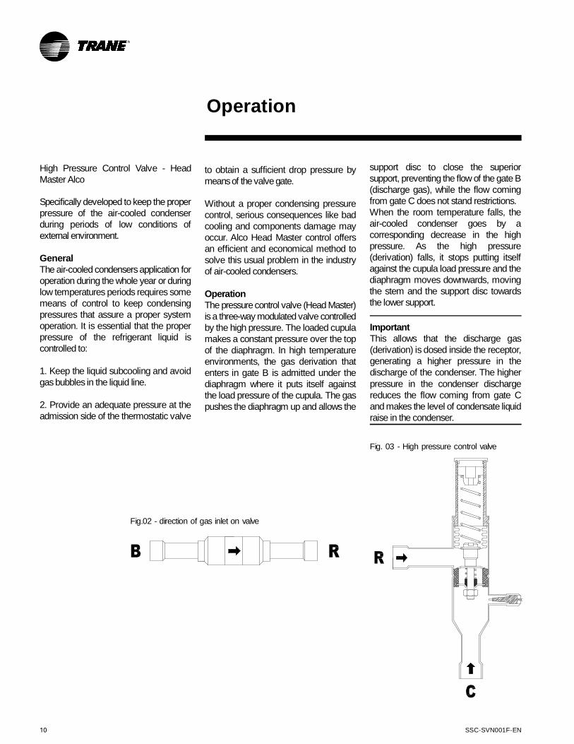
OperationThe pressurecontrol valve (Head Master)is a three-way modulated valve controlledby the high pressure. The loaded cupulamakes a constant pressure over the topof the diaphragm. In high temperatureenvironments, the gas derivation thatenters in gate B is admitted under thediaphragm where it puts itself againstthe load pressure of the cupula. The gaspushes the diaphragm up and allows the
support disc to close the superiorsupport, preventing the flow of the gate B(discharge gas), while the flow comingfrom gate C does not stand restrictions.When the room temperature falls, theair-cooled condenser goes by acorresponding decrease in the highpressure. As the high pressure(derivation) falls, it stops putting itselfagainst the cupula load pressure and thediaphragm moves downwards, movingthe stem and the support disc towardsthe lower support.
Fig.02 - direction of gas inlet on valve
Fig. 03 - High pressure control valve
ImportantThis allows that the discharge gas(derivation) is dosed inside the receptor,generating a higher pressure in thedischarge of the condenser. The higherpressure in the condenser dischargereduces the flow coming from gate Cand makes the level of condensate liquidraise in the condenser.

SSC-SVN001F-EN 11
Operation
As in all high pressure controlapplications, it is necessary anadditional capacity of the liquid recipientto prevent loss of the liquid sealing whenthe condenser is flooded. The recipienthas to be large enough to contain thesystem's total load. The total load of thesystem consists of:
A. An operational load - the pounds ofrefrigerant necessary to operate thesystem during the climatic conditions ofsummer (high room temperature).
B. An additional load that equals thenumber of pounds of refrigerant requiredto flood the condenser with liquid. Thecondenser has to be filled with liquid untilthe point to which a minimum highpressure is created for cold weatherconditions (low room temperature). If theoutside temperature falls under thedesign conditions, it will be necessary touse additional refrigerant.
A + B is the total of load necessary for asatisfactory performance of the systemduring the lowest air room temperatureconditions expected. During the summeroperation, the recipient must be sized tocontain the system's total load safely. Agood cooling takes for granted thatthe system's total load must notexceed 75% of the capacity of therecipient.
Fig. 05
Fig. 04

12 SSC-SVN001F-EN
Maintenance ProceduresThese sections describe maintenanceprocedures to be performed as part ofthe normal unit maintenance program.
Air FiltersThe washable permanent filtersprovided with the AC units should becleaned using a solution of water andneutral detergent.Put the filters into the solution, brushthem, flush with cold water and thenapply a compressed air jet.Replace throwaway filters.Do not operate the unit without filters.
MaintenanceProcedures
Sheaves and BeltsCheck if the sheaves are properlyaligned and operating correctly.1. Turn the sheaves by hand in orderto check if they can move freely.2. Check motor and fan shafts. Bothshafts should be parallel to each other.3. Verify that fan and motor sheavesare aligned. In case of sheaves withdifferent widths, align sheave centers,as shown in Fig. 2.4. Make sure the belt tension is correct.This will increase the life of motor andfan bearings.
Fig. 06 - Belt Alignment
SSC-SVN001F-EN 13
Fig. 08 - Belt Tension Adjustment
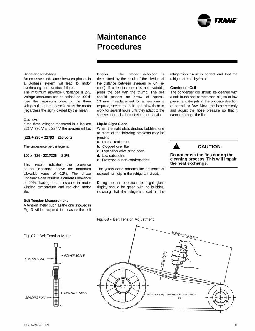
Fig. 07 - Belt Tension Meter
Unbalanced VoltageAn excessive unbalance between phases ina 3-phase system will lead to motoroverheating and eventual failures.The maximum allowable unbalance is 2%.Voltage unbalance can be defined as 100 ti-mes the maximum offset of the threevoltages (i.e. three phases) minus the mean(regardless the sign), divided by the mean.
Example:If the three voltages measured in a line are221 V, 230 V and 227 V, the average will be:
(221 + 230 + 227)/3 = 226 volts
The unbalance percentage is:
100 x (226 - 221)/226 = 2.2%
This result indicates the presenceof an unbalance above the maximumallowable value of 0.2%. The phaseunbalance can result in a current unbalanceof 20%, leading to an increase in motorwinding temperature and reducing motorlife.
Belt Tension MeasurementA tension meter such as the one showed inFig. 3 will be required to measure the belt
MaintenanceProcedures
tension. The proper deflection isdetermined by the result of the division ofthe distance between sheaves by 64 (in-ches). If a tension meter is not available,press the belt with the thumb. The beltshould present an arrow of approx.10 mm. If replacement for a new one isrequired, stretch the belts and allow them towork for several hours until they adapt to thesheave channels, then stretch them again.
Liquid Sight GlassWhen the sight glass displays bubbles, oneor more of the following problems may bepresent:a. Lack of refrigerant.b. Clogged drier filter.c. Expansion valve is too open.d. Low subcooling.e. Presence of non-condensables.
The yellow color indicates the presence ofresidual humidity in the refrigerant circuit.
During normal operation the sight glassdisplay should be green with no bubbles,indicating that the refrigerant load in the
refrigeration circuit is correct and that therefrigerant is dehydrated.
Condenser CoilThe condenser coil should be cleaned witha soft brush and compressed air jets or lowpressure water jets in the opposite directionof normal air flow. Move the hose verticallyand adjust the hose pressure so that itcannot damage the fins.
CAUTION:!
Do not crush the fins during thecleaning process. This will impairthe heat exchange.
14 SSC-SVN001F-EN
Preventive Maintenance
Periodical PreventiveMaintenance
Record operation conditions for this unitmonthly. The operation datasheet canbe a precious diagnostic tool for servicepersonnel. By noticing trends inoperating conditions the operator canoften anticipate and prevent problemsituations before they become serious.If the unit is not operating properly, referto the section on abnormal conditionsat the end of this manual.
Weekly MaintenanceWhen the equipment is operating forapprox. 30 minutes and the system isstable, check the operating conditionsand perform the following checkingprocedures:
Clean permanent air filters moreoften, depending on the job site.
Monthly MaintenanceClean the permanent air filter.
Throwaway filters should be replaced.Check fan belt tension,
alignment and condition.Clean the fan volute.Re-tighten all terminal screws.Clean the evaporator tray, the
hose and the condensate water drain.Check the liquid line sight glass.
Leak-test and repair, if required.When the liquid sight glass and
the operational conditions indicate lackof gas, measure the systemoverheating and subcooling.
When operational conditionsindicate overload, remove therefrigerant slowly (to minimize oillosses) through the Schrader servicevalve in the liquid line.
Inspect the system to detectabnormal conditions. Use a readingsheet to record unit conditions. Areading sheet completed can be aprecious tool for service personnel.
Quarterly MaintenancePerform all monthly
maintenance tasks.Check bearing and shave fixing
screws and adjust then, if required.Clean the condenser more
often, depending on the job site.Clean the evaporator more
often, depending on the job site.Check and write down fan motor
and compressor operation voltagesand currents.
Test safety controls.Check and write down
evaporator entering and leaving drybulb and wet bulb temperatures.
Check suction and dischargepressures with the manifold.
Measure and record the systemoverheating.
Measure and record the systemsubcooling.
Annual MaintenancePerform all recommended
monthly and quarterly maintenancetasks.
Have a qualified technician tocheck the adjustment and operation ofeach control, and inspect and replacecounters or controls, if required.
Remove the cabinet panels andremove rust spots.
Replace the thermal insulationand defective gaskets.
Repair the external and internalpainting, if required.
Remove rust.Inspect and clean the
condenser pipes, if required.Inspect the expansion valve
bulb. Clean it, if required. The contactbetween the bulb and the suction lineshould be excellent, and the bulbshould the properly insulated.
Measure the electrical insulationof the compressor motor.
IMPORTANT
Failure to perform preventivemaintenance tasks in the equipmentmay lead to impaired performance andeven void the equipment warranty.
IMPORTANT
Perform all inspections and maintenanceservices at the recommended intervals.This will increase equipment life andreduce possible equipment failures.
SSC-SVN001F-EN 15
50Hz
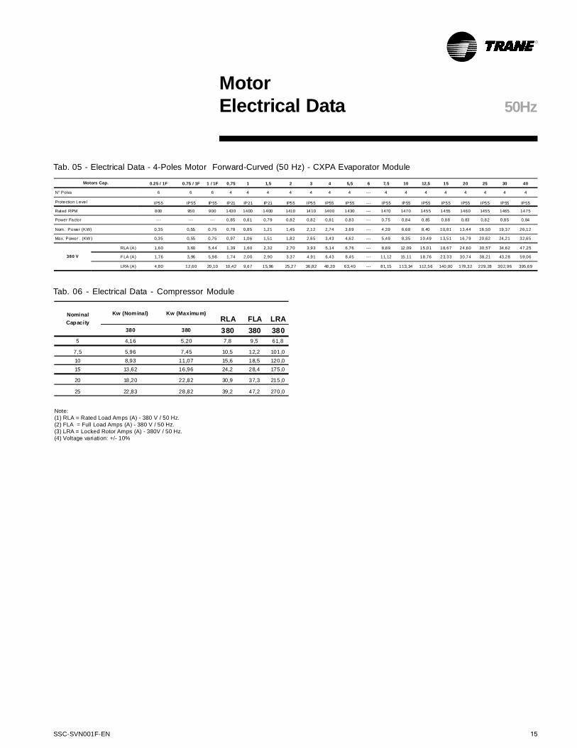
Note:(1) RLA = Rated Load Amps (A) - 380 V / 50 Hz.(2) FLA = Full Load Amps (A) - 380 V / 50 Hz.(3) LRA = Locked Rotor Amps (A) - 380V / 50 Hz.(4) Voltage variation: +/- 10%
MotorElectrical Data
Tab. 06 - Electrical Data - Compressor Module
Tab. 05 - Electrical Data - 4-Poles Motor Forward-Curved (50 Hz) - CXPA Evaporator Module
0.25 / 1F 0.75 / 1F 1 / 1F 0,75 1 1,5 2 3 4 5,5 6 7,5 10 12,5 15 20 25 30 40
N° Poles 6 6 6 4 4 4 4 4 4 4 --- 4 4 4 4 4 4 4 4
Protection Level IP55 IP55 IP55 IP21 IP21 IP21 IP55 IP55 IP55 IP55 --- IP55 IP55 IP55 IP55 IP55 IP55 IP55 IP55
Rated RPM 800 950 900 1430 1400 1400 1410 1410 1400 1430 --- 1470 1470 1455 1455 1460 1455 1465 1475
Power Factor --- --- --- 0,85 0,81 0,79 0,82 0,82 0,81 0,83 --- 0,75 0,84 0,85 0,88 0,83 0,82 0,85 0,84
Nom. Power (KW) 0,35 0,55 0,75 0,78 0,85 1,21 1,45 2,12 2,74 3,69 --- 4,39 6,68 8,40 10,81 13,44 16,50 19,37 26,12
Max. Power . (KW ) 0,35 0,55 0,75 0,97 1,06 1,51 1,82 2,65 3,43 4,62 --- 5,49 8,35 10,49 13,51 16,79 20,62 24,21 32,65
RLA (A) 1,60 3,60 5,44 1,39 1,60 2,32 2,70 3,93 5,14 6,76 --- 8,89 12,09 15,01 18,67 24,60 30,57 34,62 47,25
F LA (A) 1,76 3,96 5,98 1,74 2,00 2,90 3,37 4,91 6,43 8,45 --- 11,12 15,11 18,76 23,33 30,74 38,21 43,28 59,06
LRA (A) 4,80 12,60 20,10 10,42 9,67 15,96 25,27 36,82 48,20 63,40 --- 81,15 113,34 112,56 140,00 178,32 229,28 302,96 395,69
Motors Cap.
380 V
Kw (Nominal) Kw (Maximu m)RLA FLA LRA
380 380 380 380 380
5 4,16 5,20 7,8 9,5 61,8
7,5 5,96 7,45 10,5 12,2 101,0
10 8,93 11,07 15,6 18,5 120,0
15 13,62 16,96 24,2 28,4 175,0
20 18,20 22,82 30,9 37,3 215,0
25 22,83 28,82 39,2 47,2 270,0
Nominal
Capacity
16 SSC-SVN001F-EN
MotorElectrical Data
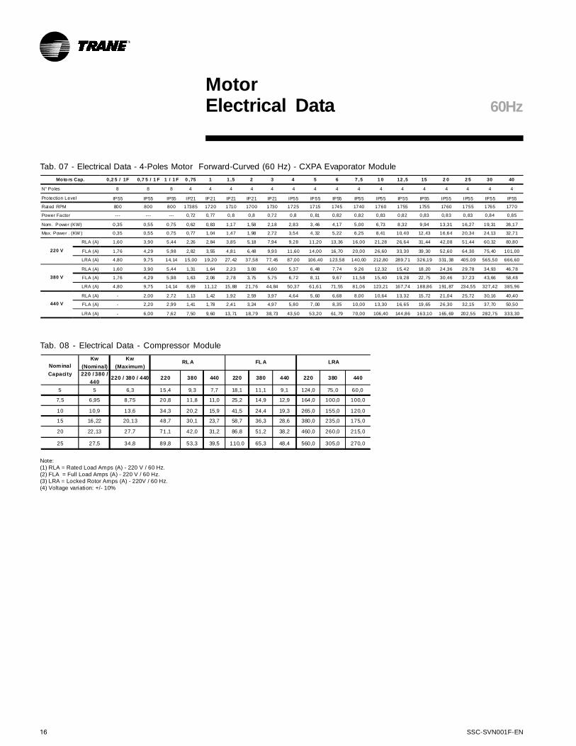
Tab. 07 - Electrical Data - 4-Poles Motor Forward-Curved (60 Hz) - CXPA Evaporator Module
Note:(1) RLA = Rated Load Amps (A) - 220 V / 60 Hz.(2) FLA = Full Load Amps (A) - 220 V / 60 Hz.(3) LRA = Locked Rotor Amps (A) - 220V / 60 Hz.(4) Voltage variation: +/- 10%
60Hz
Tab. 08 - Electrical Data - Compressor Module
0,2 5 / 1F 0,7 5 / 1 F 1 / 1 F 0 ,75 1 1 ,5 2 3 4 5 6 7 ,5 1 0 12 ,5 15 2 0 2 5 30 40
N° Poles 8 8 8 4 4 4 4 4 4 4 4 4 4 4 4 4 4 4 4
Protection Level IP55 IP55 IP55 IP21 IP21 IP21 IP21 IP21 IP55 IP55 IP55 IP55 IP55 IP55 IP55 IP55 IP55 IP55 IP55
Rated RPM 800 800 800 17385 1720 1710 1700 1730 1725 1715 1745 1740 1760 1755 1755 1760 1755 1765 1770
Power Factor --- --- --- 0,72 0,77 0,8 0,8 0,72 0,8 0,81 0,82 0,82 0,83 0,82 0,83 0,83 0,83 0,84 0,85
Nom. Power (KW) 0,35 0,55 0,75 0,62 0,83 1,17 1,58 2,18 2,83 3,46 4,17 5,00 6,73 8,32 9,94 13,31 16,27 19,31 26,17
Max. Power . (KW ) 0,35 0,55 0,75 0,77 1,04 1,47 1,98 2,72 3,54 4,32 5,22 6,25 8,41 10,40 12,43 16,64 20,34 24,13 32,71
RLA (A) 1,60 3,90 5,44 2,26 2,84 3,85 5,18 7,94 9,28 11,20 13,36 16,00 21,28 26,64 31,44 42,08 51,44 60,32 80,80
FLA (A) 1,76 4,29 5,98 2,82 3,55 4,81 6,48 9,93 11,60 14,00 16,70 20,00 26,60 33,30 39,30 52,60 64,30 75,40 101,00
LRA (A) 4,80 9,75 14,14 15,00 19,20 27,42 37,58 77,45 87,00 106,40 123,58 140,00 212,80 289,71 326,19 331,38 405,09 565,50 666,60
RLA (A) 1,60 3,90 5,44 1,31 1,64 2,23 3,00 4,60 5,37 6,48 7,74 9,26 12,32 15,42 18,20 24,36 29,78 34,93 46,78
FLA (A) 1,76 4,29 5,98 1,63 2,06 2,78 3,75 5,75 6,72 8,11 9,67 11,58 15,40 19,28 22,75 30,46 37,23 43,66 58,48
LRA (A) 4,80 9,75 14,14 8,69 11,12 15,88 21,76 44,84 50,37 61,61 71,55 81,06 123,21 167,74 188,86 191,87 234,55 327,42 385,96
RLA (A) - 2,00 2,72 1,13 1,42 1,92 2,59 3,97 4,64 5,60 6,68 8,00 10,64 13,32 15,72 21,04 25,72 30,16 40,40
FLA (A) - 2,20 2,99 1,41 1,78 2,41 3,24 4,97 5,80 7,00 8,35 10,00 13,30 16,65 19,65 26,30 32,15 37,70 50,50
LRA (A) - 6,00 7,62 7,50 9,60 13,71 18,79 38,73 43,50 53,20 61,79 70,00 106,40 144,86 163,10 165,69 202,55 282,75 333,30
Moto rs Cap.
220 V
380 V
440 V
Kw
(Nominal)
Kw
(Maximum)
220 / 380 /
440220 / 380 / 440 220 380 440 220 380 440 220 380 440
5 5 6,3 15,4 9,3 7,7 18,1 11,1 9,1 124,0 75,0 60,0
7,5 6,95 8,75 20,8 11,8 11,0 25,2 14,9 12,9 164,0 100,0 100,0
10 10,9 13,6 34,3 20,2 15,9 41,5 24,4 19,3 265,0 155,0 120,0
15 16,22 20,13 48,7 30,1 23,7 58,7 36,3 28,6 380,0 235,0 175,0
20 22,13 27,7 71,1 42,0 31,2 86,8 51,2 38,2 460,0 260,0 215,0
25 27,5 34,8 89,8 53,3 39,5 110,0 65,3 48,4 560,0 305,0 270,0
Nominal
Capacity
RL A FL A LRA
SSC-SVN001F-EN 17
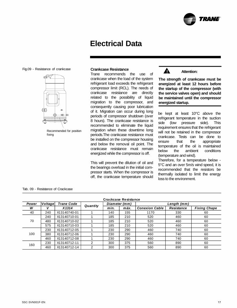
Fig.09 - Resistance of crankcase
Recommended for positionfixing
Crankcase ResistanceTrane recommends the use ofcrankcase when the load of the systemrefrigerant load exceeds the refrigerantcompressor limit (RCL). The needs ofcrankcase resistance are directlyrelated to the possibility of liquidmigration to the compressor, andconsequently causing poor lubricationof it. Migration can occur during longperiods of compressor shutdown (over8 hours). The crankcase resistance isrecommended to eliminate the liquidmigration when these downtime longperiods.The crankcase resistance mustbe installed on the compressor housingand below the removal oil point. Thecrankcase resistance must remainenergized while the compressor is off.
This will prevent the dilution of oil andthe bearings overload in the initial com-pressor starts. When the compressor isoff, the crankcase temperature should
Tab. 09 - Resistance of Crackcase
Power Voltage Trane Code
W V X1314 min. máx. Conexion Cable Resistance Fixing Chape
40 240 X13140740-01 1 140 155 1170 330 60
240 X13140710-01 1 185 210 520 460 60
480 X13140710-02 1 185 210 520 460 60
575 X13140710-03 1 185 210 520 460 60
230 X13140712-05 1 230 290 460 740 60
380 X13140712-06 1 230 290 460 740 60
460 X13140712-08 1 230 290 460 740 60
230 X13140712-11 2 300 375 560 890 60
460 X13140712-14 2 300 375 560 890 60
70
100
160
Crackcase Resistance
QuantityDiameter (mm) Length (mm)
Electrical Data
be kept at least 10°C above therefrigerant temperature in the suctionside (low pressure side). Thisrequirement ensures that the refrigerantwill not be retained in the compressorcrankcase. Tests can be done toensure that the appropriatetemperature of the oil is maintainedbelow the ambient conditions(temperature and wind).Therefore, for a temperature below -5°C and an over 5m/s wind speed, it isrecommended that the resistors bethermally isolated to limit the energyloss to the environment.
Attention:
The strength of crankcase must beenergized at least 12 hours beforethe startup of the compressor (withthe service valves open) and shouldbe maintained until the compressorenergized startup.
!
18 SSC-SVN001F-EN
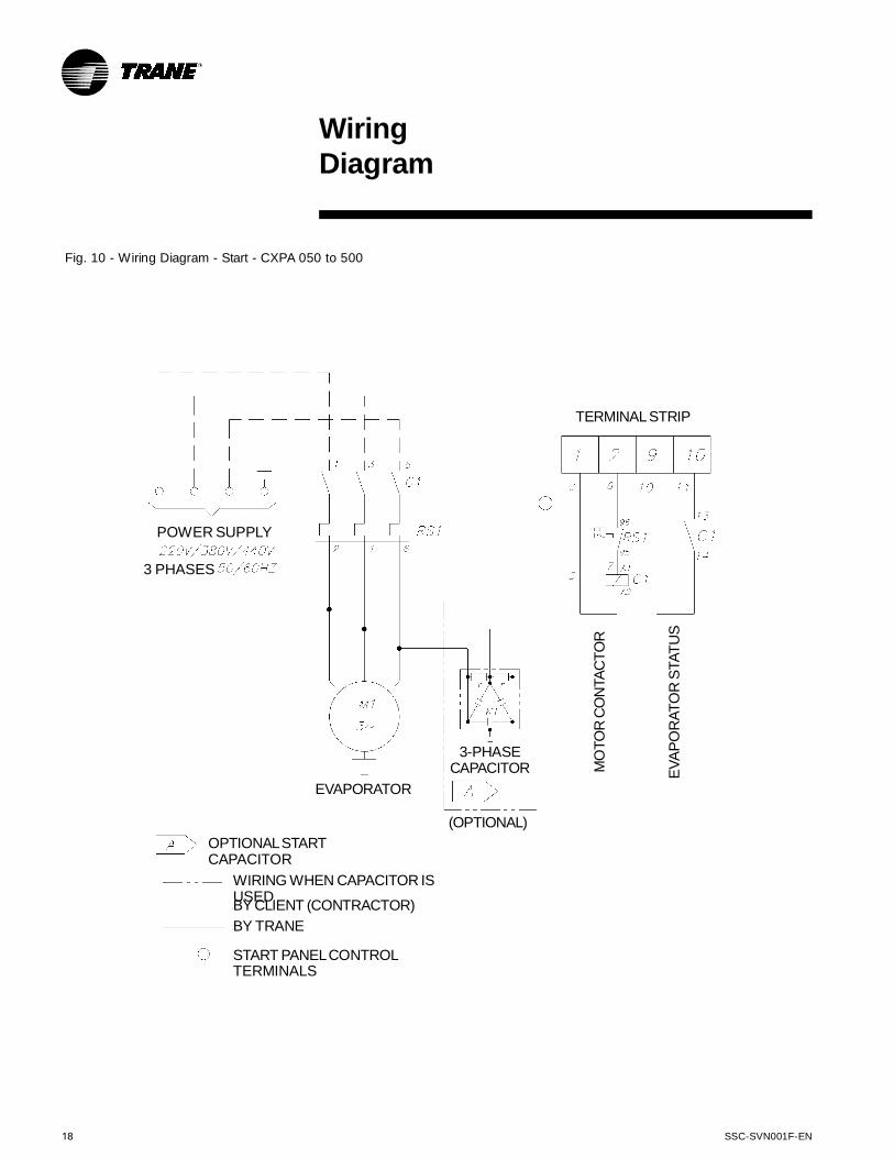
Fig. 10 - Wiring Diagram - Start - CXPA 050 to 500
WiringDiagram
POWER SUPPLY
3 PHASES
TERMINALSTRIP
MO
TO
RC
ON
TA
CT
OR
EV
AP
OR
AT
OR
STA
TU
S
3-PHASECAPACITOR
(OPTIONAL)
EVAPORATOR
OPTIONALSTARTCAPACITOR
WIRING WHEN CAPACITOR ISUSEDBY CLIENT (CONTRACTOR)
BY TRANE
START PANELCONTROLTERMINALS

SSC-SVN001F-EN 19
DimensionalData Fan/Coil
Fig. 11 - Dimensional Data - Fan Module - 050 to 100
Fig. 12a - Vertical Discharge Fig. 12c - Downflow DischargeFig. 12b - Horizontal Discharge
Fig. 13 - Dimensional Data - Coil Module - 050 to 100
Power Input
Dia. 27 mm
Control
Dia. 27 mm
Unit:mm
Unit:mm
Access Covers
Electrical
Panel
Motorand
Electrical Panel
Access Cover
FR
ON
T
FR
ON
T
FR
ON
T
FILTERS
DRAIN
(external)
Model 050 075 100A 950 1135 1420B 485 565 660C 510 590 690D 290 341 403B 326 386 473C 167 224 373D 457 525 574
Model 050 075 100A 950 1135 1420B 485 565 660C 510 590 585D 140 140 245

20 SSC-SVN001F-EN
DimensionalData
Fig. 14 - Dimensional Data - Fan Module - 125 and 150
Fig. 16 - Dimensional Data - Coil Module - 125 and 150
Fig. 15a - Vertical Discharge Fig. 15b - Horizontal Discharge Fig. 15c - Downflow Discharge
Motor and
Electrical Panel
Access Cover
Power Inout
Dia. 27 mm
Control
Dia. 27 mm
Unit:mm
Access Covers
Electrical
Panel
FR
ON
T
FR
ON
T
FILTERS
DRAIN
(external)
Model 125 150A 1470 1470B 580 580C 770 940D 155 155
Fan/Coil
SSC-SVN001F-EN 21
DimensionalData
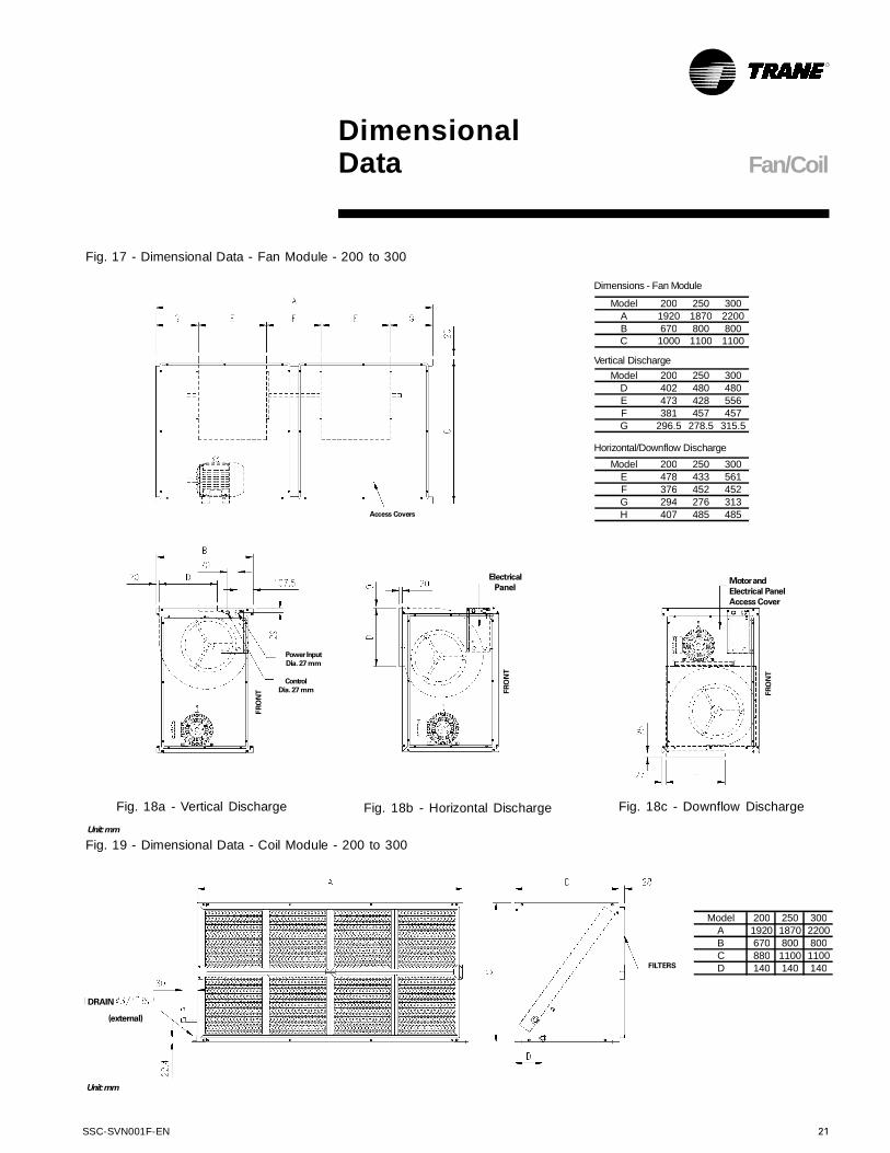
Fig. 17 - Dimensional Data - Fan Module - 200 to 300
Fig. 19 - Dimensional Data - Coil Module - 200 to 300
Unit:mm
Unit:mm
Power Input
Dia. 27 mm
Control
Dia. 27 mm
Access Covers
Fig. 18a - Vertical Discharge Fig. 18c - Downflow DischargeFig. 18b - Horizontal Discharge
FR
ON
T
FR
ON
T FR
ON
T
Electrical
PanelMotorand
Electrical Panel
Access Cover
FILTERS
DRAIN
(external)
Model 200 250 300A 1920 1870 2200B 670 800 800C 880 1100 1100D 140 140 140
Horizontal/Downflow Discharge
Vertical Discharge
Dimensions - Fan Module
Model 200 250 300E 478 433 561F 376 452 452G 294 276 313H 407 485 485
Model 200 250 300D 402 480 480E 473 428 556F 381 457 457G 296.5 278.5 315.5
Model 200 250 300
A 1920 1870 2200
B 670 800 800C 1000 1100 1100
Fan/Coil

22 SSC-SVN001F-EN
Fig. 20 - Dimensional Data - Fan Module - 350 to 500
Fig. 22 - Dimensional Data - Coil Module - 350 to 500
DimensionalData
Unit:mm
Unit:mm
Power Input
Dia. 27 mm
Control
Dia. 27 mm
Access Covers
Fig. 21a - Vertical Discharge Fig. 21c - Downflow DischargeFig. 21b - Horizontal Discharge
FR
ON
T
FR
ON
T
FR
ON
T
Electrical Panel
Motorand
Electrical Panel
Access Cover
FILTERS
DRAIN
(external)
Model 350 400 500A 2770 2770 2770B 800 900 900C 1100 1220 1490D 140 140 140
Horizontal/Downflow Discharge
Vertical Discharge
Dimensions - Fan Module
Model 350 400 500D 478 561 561E 379 311 311F 289 232.5 232.5G 401 423 423H 407 485 485
Model 350 400 500C 402 480 480D 473 556 556E 384 316 316F 291.5 235 235
Model 350 400 500A 800 900 900
B 1100 1220 1220
Fan/Coil
SSC-SVN001F-EN 23
CoilModule(Refrigerant Circuits)
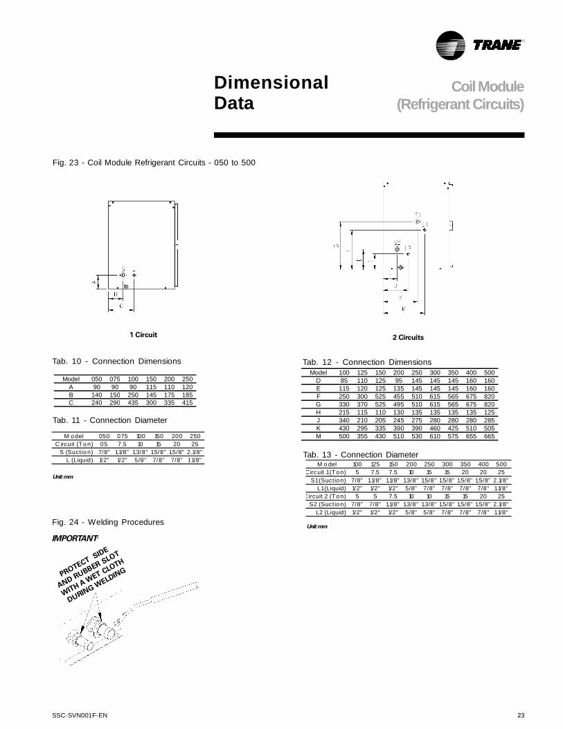
Fig. 23 - Coil Module Refrigerant Circuits - 050 to 500
Tab. 10 - Connection Dimensions Tab. 12 - Connection Dimensions
1 Circuit 2 Circuits
Tab. 11 - Connection Diameter
Tab. 13 - Connection Diameter
Unit:mm
Unit:mm
IMPORTANT:
PROTECTSID
E
ANDRUBBER SLOT
WITH
A WET CLOTH
DURING
WELDING
Model 100 125 150 200 250 300 350 400 500D 85 110 125 95 145 145 145 160 160E 115 120 125 135 145 145 145 160 160F 250 300 525 455 510 615 565 675 820G 330 370 525 495 510 615 565 675 820H 215 115 110 130 135 135 135 135 125J 340 210 205 245 275 280 280 280 285K 430 295 335 390 390 460 425 510 505M 500 355 430 510 530 610 575 655 665M o del 050 075 100 150 200 250
C ircuit (To n) 05 7.5 10 15 20 25
S (Suctio n) 7/8" 1.1/8" 1.3/8" 1.5/8" 1.5/8" 2.1/8"
L (Liquid) 1/2" 1/2" 5/8" 7/8" 7/8" 11/8"
Model 050 075 100 150 200 250
A 90 90 90 115 110 120
B 140 150 250 145 175 185C 240 290 435 300 335 415
M o del 100 125 150 200 250 300 350 400 500
Circuit 1(To n) 5 7.5 7.5 10 15 15 20 20 25
S1(Suctio n) 7/8" 1.1/8" 1.1/8" 1.3/8" 1.5/8" 1.5/8" 1.5/8" 1.5/8" 2.1/8"
L1(Liquid) 1/2" 1/2" 1/2" 5/8" 7/8" 7/8" 7/8" 7/8" 1.1/8"
C ircuit 2 (To n) 5 5 7.5 10 10 15 15 20 25
S2 (Suctio n) 7/8" 7/8" 1.1/8" 1.3/8" 1.3/8" 1.5/8" 1.5/8" 1.5/8" 2.1/8"
L2 (Liquid) 1/2" 1/2" 1/2" 5/8" 5/8" 7/8" 7/8" 7/8" 1.1/8"
DimensionalData
Fig. 24 - Welding Procedures

24 SSC-SVN001F-EN
ModuleAssembly
DimensionalData
Fig. 26 - Fan and Coil Module Assembly - CXPA 050 to 500 - Horizontal - Superior View
PLAN
Oblong 11.5x25
Fastening spots
9.5-dia. hole
Fastening spots
MODULE UNION
(INTERNAL FIXATION)
Fig. 25 - Fan and Coil Module Assembly - CXPA 050 to 500 - Horizontal
Model 050 075 100 125 150 200 250 300 350 400 500A 950 1135 1420 1470 1470 1920 1870 2200 2770 2770 2770B 970 1130 1320 1160 1160 1340 1600 1600 1600 1800 1800
C 510 590 690 830 830 1000 1100 1100 1100 1220 1220D 510 590 585 770 940 880 1100 1100 1100 1220 1490
Model 050 075 100 125 150 200 250 300 350 400 500A 980 1165 1450 1500 1500 1950 1900 2230 2800 2800 2800B 405 485 580 500 500 590 720 720 720 820 820
C 1010 1195 1480 1530 1530 1980 1930 2260 2830 2830 2830D 285 365 460 380 380 470 600 600 600 700 700E 883 1068 1353 1403 1403 1853 1803 2133 2703 2703 2703F 140 140 140 190 190 190 190 190 190 190 190G 100 100 100 150 150 150 150 150 150 150 150
SSC-SVN001F-EN 25
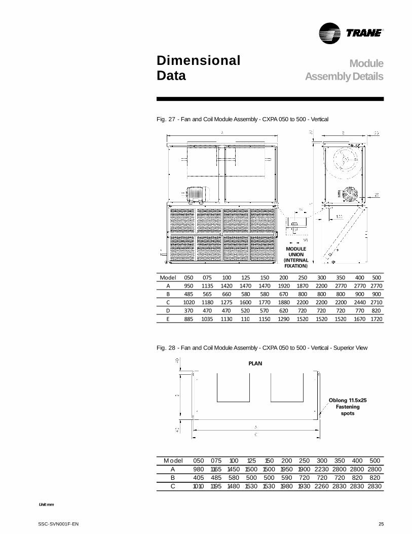
Model 050 075 100 125 150 200 250 300 350 400 500
A 950 1135 1420 1470 1470 1920 1870 2200 2770 2770 2770
B 485 565 660 580 580 670 800 800 800 900 900
C 1020 1180 1275 1600 1770 1880 2200 2200 2200 2440 2710
D 370 470 470 520 570 620 720 720 720 770 820
E 885 1035 1130 110 1150 1290 1520 1520 1520 1670 1720
ModuleAssemblyDetails
Fig. 27 - Fan and Coil Module Assembly - CXPA 050 to 500 - Vertical
Unit:mm
MODULE
UNION
(INTERNAL
FIXATION)
DimensionalData
Fig. 28 - Fan and Coil Module Assembly - CXPA 050 to 500 - Vertical - Superior View
M odel 050 075 100 125 150 200 250 300 350 400 500
A 980 1165 1450 1500 1500 1950 1900 2230 2800 2800 2800
B 405 485 580 500 500 590 720 720 720 820 820
C 1010 1195 1480 1530 1530 1980 1930 2260 2830 2830 2830
PLAN
Oblong 11.5x25
Fastening
spots
26 SSC-SVN001F-EN
Considerations forModules
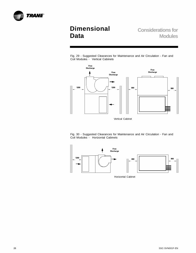
Fig. 29 - Suggested Clearances for Maintenance and Air Circulation - Fan andCoil Modules - Vertical Cabinets
Fig. 30 - Suggested Clearances for Maintenance and Air Circulation - Fan andCoil Modules - Horizontal Cabinets
Vertical Cabinet
12001200
Free
Discharge
Free
Discharge
800 800
Free
Discharge
Horizontal Cabinet
1200
Free
Discharge
800 800
DimensionalData

SSC-SVN001F-EN 27
DimensionalData TRAE
Fig. 31 - Dimensions - Condensing Units TRAE 050
Fig. 32 - Dimensions - Condensing Units TRAE 075
28 SSC-SVN001F-EN
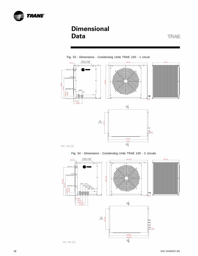
Fig. 33 - Dimensions - Condensing Units TRAE 100 - 1 circuit
Fig. 34 - Dimensions - Condensing Units TRAE 100 - 2 circuits
TRAE
DimensionalData

SSC-SVN001F-EN 29
Fig. 35 - Dimensions - Condensing Units TRAE 125
Fig. 36 - Dimensions - Condensing Units TRAE 150 - 1 circuit
TRAE
DimensionalData
30 SSC-SVN001F-EN
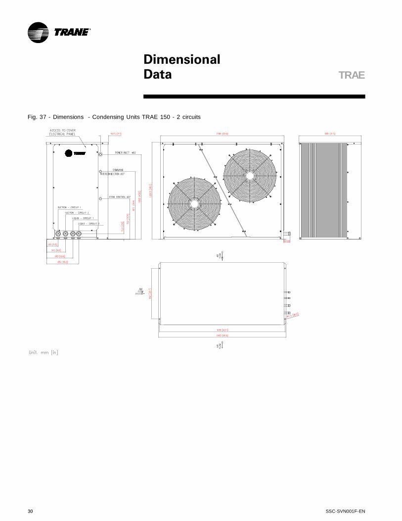
Fig. 37 - Dimensions - Condensing Units TRAE 150 - 2 circuits
TRAE
DimensionalData
SSC-SVN001F-EN 31
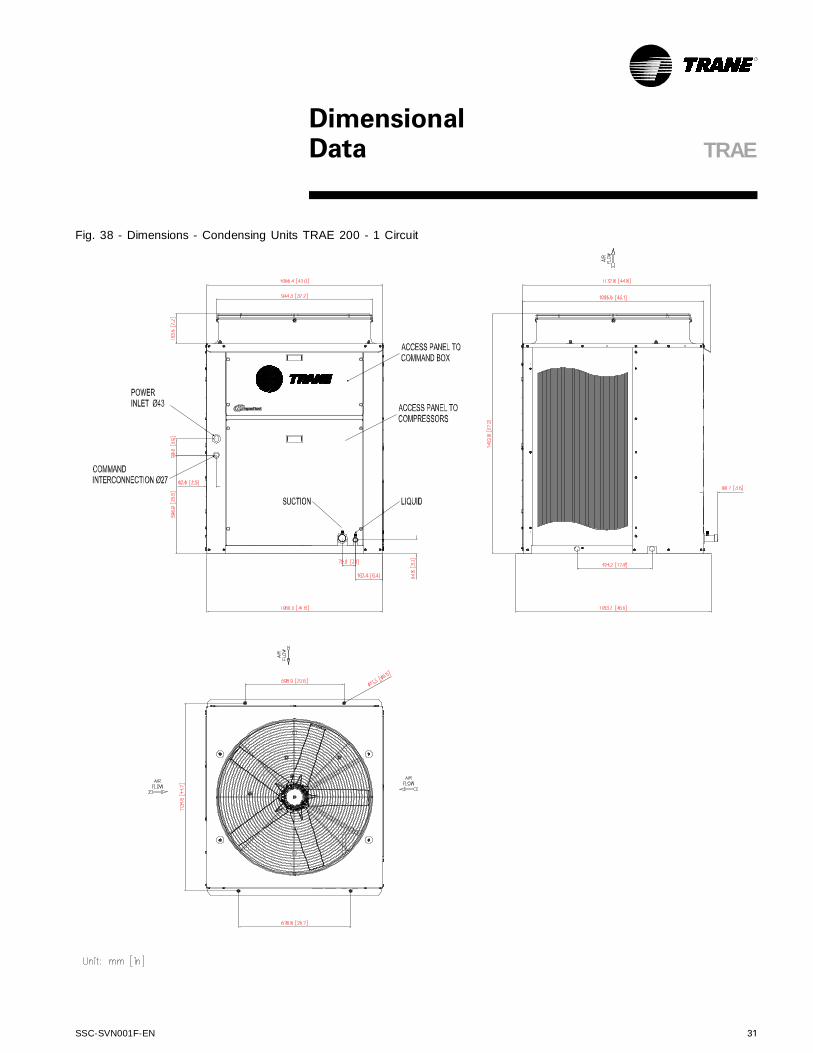
Fig. 38 - Dimensions - Condensing Units TRAE 200 - 1 Circuit
TRAE
DimensionalData

32 SSC-SVN001F-EN
TRAE
DimensionalData
Fig. 39 - Dimensions - Condensing Units TRAE 200 - 2 Circuits
SSC-SVN001F-EN 33
TRAE
DimensionalData
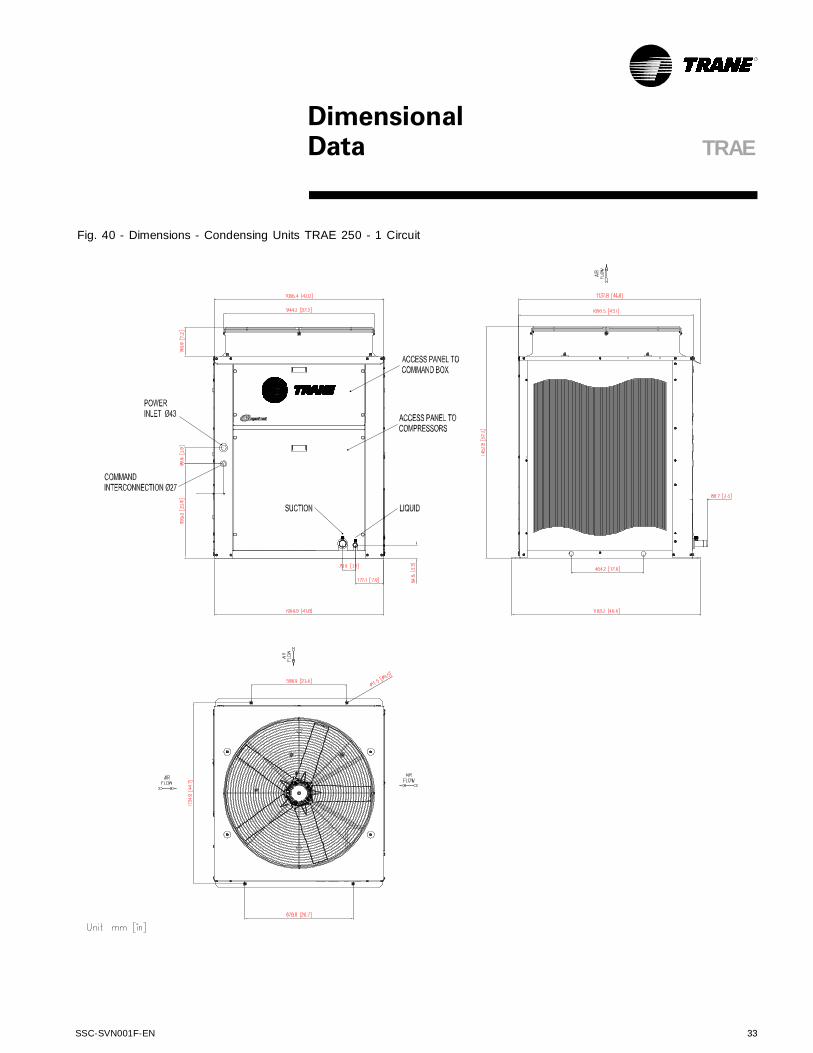
Fig. 40 - Dimensions - Condensing Units TRAE 250 - 1 Circuit
34 SSC-SVN001F-EN
TRAE
DimensionalData
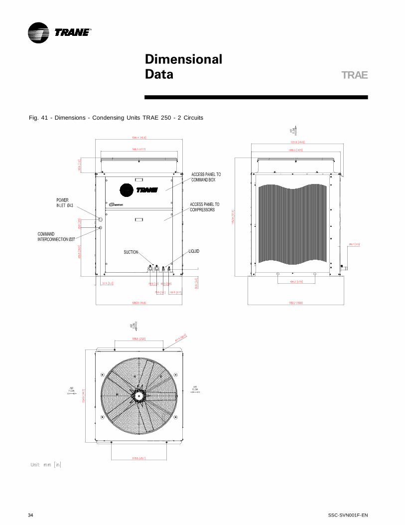
Fig. 41 - Dimensions - Condensing Units TRAE 250 - 2 Circuits
SSC-SVN001F-EN 35
TRAE
DimensionalData
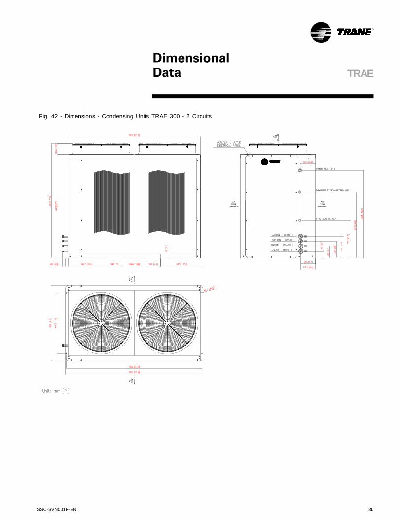
Fig. 42 - Dimensions - Condensing Units TRAE 300 - 2 Circuits

36 SSC-SVN001F-EN
Tab. 14 - Dimensions - TRCE
Tab.15 - Dimensions - TRCE
Tab. 16 - Connection dimensions - TRCE
Fig. 43 - Connections - condensing unit TRCE
Cota 050 075 100 125 150
A 922 1146 1420 1640 1640
B 1373 1474 1525 1600 1829
C 560 560 560 560 560
D 341 341 290 341 341
E 374 480 402 432 432
F 386 386 326 386 386
G ---- ---- 230 255 255
H 778 879 930 1005 1234
K 813 914 965 1040 1269
L 560 560 560 560 560
Modelo
Fig. 44 - Dimensions - TRCE
050 075 100C/1 100C/2 125C/1 125C/2 150C/1 150C/2
S1 --- --- --- 7/8" --- 1 1/8" --- 1 1/8"
L1 --- --- --- 1/2" --- 1/2" --- 1/2"
S2 / S 7/8" 1 1/8" 1 3/8" 7/8" --- 7/8" 1 5/8" 1 1/8"
L2 / L 1/2" 1/2" 5/8" 1/2" --- 1/2" 7/8" 1/2"
Models TRCE
Co
ne
cti
on
s
(po
l)
C D E J M
50 560 20 341 711 778
75 560 20 341 813 879
100C/1
100C/2
125C/2 560 20 341 940 1005
150C/1
150C/2560
Mod
els
TR
CE
864
1234116834120
560 95 290 930
Measures (mm)
DimensionalData TRCE
A
B
D
F
F
C
H
100.0
40.0
40.0
E
80.0
80.0
G
70.0
VIEW"A"
POWER INPUT
ONBOTH SIDES
80.0
60.0
14
0.0 210
.0
28
0.0
350
.0
VIEW"A"
C
D E
Jh
eig
ht
ale
tad
a
100
80
20
59
70
M
TRCE 020 A 150
Ø43
Ø27
L2/L
S2/S
L1
S1
Powerinput onbothside

SSC-SVN001F-EN 37
Aplication ConsiderationsTRAE / TRCE
Fig. 45 - Clearances required for Maintenance and Air Circulation - TRAE
Suggestes clearances TRAE 050 to 150 - Horizontal Discharge
Fig. 46 - Suggested clearances TRAE 200 to 300 - Vertical Discharge
Fig. 47 - Suggested Clearances for Maintenance and Air Circulation - Condensing Unit TRCE 050 to 150.
Unit: mm
Free discharge
Freedischarge
Freedischarge
800 800 1200 1200
DimensionalData
38 SSC-SVN001F-EN
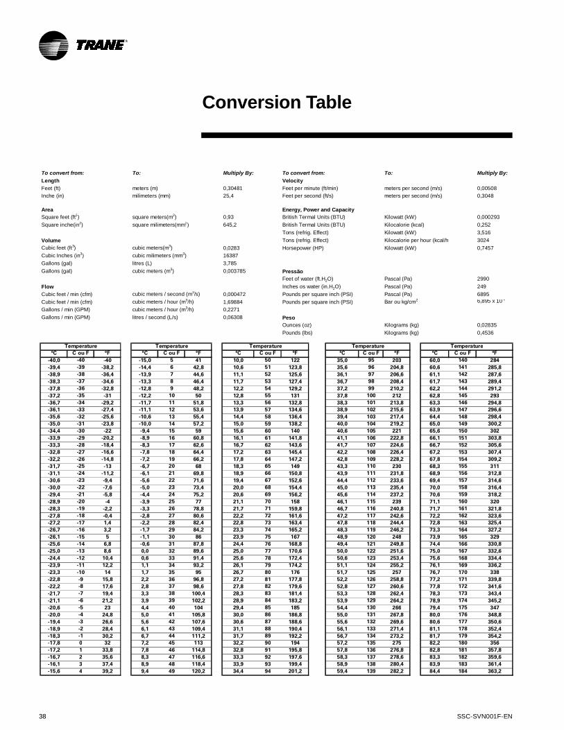
Conversion Table
Multiply By: Multiply By:
0,30481 0,00508
25,4 0,3048
0,93 0,000293
645,2 0,252
3,516
3024
0,0283 0,7457
16387
3,785
0,003785
2990
249
0,000472 6895
1,69884 6,895 x 10-2
0,2271
0,06308
0,02835
0,4536
°C C ou F °F °C C ou F °F °C C ou F °F °C C ou F °F °C C ou F °F
-40,0 -40 -40 -15,0 5 41 10,0 50 122 35,0 95 203 60,0 140 284
-39,4 -39 -38,2 -14,4 6 42,8 10,6 51 123,8 35,6 96 204,8 60,6 141 285,8
-38,9 -38 -36,4 -13,9 7 44,6 11,1 52 125,6 36,1 97 206,6 61,1 142 287,6
-38,3 -37 -34,6 -13,3 8 46,4 11,7 53 127,4 36,7 98 208,4 61,7 143 289,4
-37,8 -36 -32,8 -12,8 9 48,2 12,2 54 129,2 37,2 99 210,2 62,2 144 291,2
-37,2 -35 -31 -12,2 10 50 12,8 55 131 37,8 100 212 62,8 145 293
-36,7 -34 -29,2 -11,7 11 51,8 13,3 56 132,8 38,3 101 213,8 63,3 146 294,8
-36,1 -33 -27,4 -11,1 12 53,6 13,9 57 134,6 38,9 102 215,6 63,9 147 296,6
-35,6 -32 -25,6 -10,6 13 55,4 14,4 58 136,4 39,4 103 217,4 64,4 148 298,4
-35,0 -31 -23,8 -10,0 14 57,2 15,0 59 138,2 40,0 104 219,2 65,0 149 300,2
-34,4 -30 -22 -9,4 15 59 15,6 60 140 40,6 105 221 65,6 150 302
-33,9 -29 -20,2 -8,9 16 60,8 16,1 61 141,8 41,1 106 222,8 66,1 151 303,8
-33,3 -28 -18,4 -8,3 17 62,6 16,7 62 143,6 41,7 107 224,6 66,7 152 305,6
-32,8 -27 -16,6 -7,8 18 64,4 17,2 63 145,4 42,2 108 226,4 67,2 153 307,4
-32,2 -26 -14,8 -7,2 19 66,2 17,8 64 147,2 42,8 109 228,2 67,8 154 309,2
-31,7 -25 -13 -6,7 20 68 18,3 65 149 43,3 110 230 68,3 155 311
-31,1 -24 -11,2 -6,1 21 69,8 18,9 66 150,8 43,9 111 231,8 68,9 156 312,8
-30,6 -23 -9,4 -5,6 22 71,6 19,4 67 152,6 44,4 112 233,6 69,4 157 314,6
-30,0 -22 -7,6 -5,0 23 73,4 20,0 68 154,4 45,0 113 235,4 70,0 158 316,4
-29,4 -21 -5,8 -4,4 24 75,2 20,6 69 156,2 45,6 114 237,2 70,6 159 318,2
-28,9 -20 -4 -3,9 25 77 21,1 70 158 46,1 115 239 71,1 160 320
-28,3 -19 -2,2 -3,3 26 78,8 21,7 71 159,8 46,7 116 240,8 71,7 161 321,8
-27,8 -18 -0,4 -2,8 27 80,6 22,2 72 161,6 47,2 117 242,6 72,2 162 323,6
-27,2 -17 1,4 -2,2 28 82,4 22,8 73 163,4 47,8 118 244,4 72,8 163 325,4
-26,7 -16 3,2 -1,7 29 84,2 23,3 74 165,2 48,3 119 246,2 73,3 164 327,2
-26,1 -15 5 -1,1 30 86 23,9 75 167 48,9 120 248 73,9 165 329
-25,6 -14 6,8 -0,6 31 87,8 24,4 76 168,8 49,4 121 249,8 74,4 166 330,8
-25,0 -13 8,6 0,0 32 89,6 25,0 77 170,6 50,0 122 251,6 75,0 167 332,6
-24,4 -12 10,4 0,6 33 91,4 25,6 78 172,4 50,6 123 253,4 75,6 168 334,4
-23,9 -11 12,2 1,1 34 93,2 26,1 79 174,2 51,1 124 255,2 76,1 169 336,2
-23,3 -10 14 1,7 35 95 26,7 80 176 51,7 125 257 76,7 170 338
-22,8 -9 15,8 2,2 36 96,8 27,2 81 177,8 52,2 126 258,8 77,2 171 339,8
-22,2 -8 17,6 2,8 37 98,6 27,8 82 179,6 52,8 127 260,6 77,8 172 341,6
-21,7 -7 19,4 3,3 38 100,4 28,3 83 181,4 53,3 128 262,4 78,3 173 343,4
-21,1 -6 21,2 3,9 39 102,2 28,9 84 183,2 53,9 129 264,2 78,9 174 345,2
-20,6 -5 23 4,4 40 104 29,4 85 185 54,4 130 266 79,4 175 347
-20,0 -4 24,8 5,0 41 105,8 30,0 86 186,8 55,0 131 267,8 80,0 176 348,8
-19,4 -3 26,6 5,6 42 107,6 30,6 87 188,6 55,6 132 269,6 80,6 177 350,6
-18,9 -2 28,4 6,1 43 109,4 31,1 88 190,4 56,1 133 271,4 81,1 178 352,4
-18,3 -1 30,2 6,7 44 111,2 31,7 89 192,2 56,7 134 273,2 81,7 179 354,2
-17,8 0 32 7,2 45 113 32,2 90 194 57,2 135 275 82,2 180 356
-17,2 1 33,8 7,8 46 114,8 32,8 91 195,8 57,8 136 276,8 82,8 181 357,8
-16,7 2 35,6 8,3 47 116,6 33,3 92 197,6 58,3 137 278,6 83,3 182 359,6
-16,1 3 37,4 8,9 48 118,4 33,9 93 199,4 58,9 138 280,4 83,9 183 361,4
-15,6 4 39,2 9,4 49 120,2 34,4 94 201,2 59,4 139 282,2 84,4 184 363,2
TemperatureTemperature Temperature Temperature
Cubic feet (ft3)
Volume
Cubic Inches (in3)
Gallons (gal)
Gallons (gal)
Area
Square feet (ft2)
Square inche(in2)
To convert from:
Length
Feet (ft)
Inche (in)
litres (L)
Gallons / min (GPM)
Cubic feet / min (cfm)
Flow
Gallons / min (GPM)
Cubic feet / min (cfm)
cubic meters (m3)
cubic meters / second (m3/s)
Temperature
cubic meters / hour (m3/h)
cubic meters / hour (m3/h)
litres / second (L/s)
To:
meters (m)
milimeters (mm)
square meters(m2)
square milimeters(mm2)
cubic meters(m3)
cubic milimeters (mm3)
To convert from:
Velocity
Feet per minute (ft/min)
Feet per second (ft/s)
Energy, Power and Capacity
British Termal Units (BTU)
British Termal Units (BTU)
Tons (refrig. Effect)
Tons (refrig. Effect)
Horsepower (HP)
Pressão
Feet of water (ft.H2O)
Inches os water (in.H2O)
Pounds per square inch (PSI)
Pounds per square inch (PSI)
Peso
Ounces (oz)
Pounds (lbs) Kilograms (kg)
Kilograms (kg)
Bar ou kg/cm2
Pascal (Pa)
Pascal (Pa)
Pascal (Pa)
Kilowatt (kW)
Kilocalorie per hour (kcal/h)
Kilowatt (kW)
Kilocalorie (kcal)
Kilowatt (kW)
meters per second (m/s)
meters per second (m/s)
To:
© 2016 Trane
All rights reserved
SSC-SVN001F EN November 2016
Supersedes SSC-SVN001E EN September 2015
Trane optimizes the performance of homes and buildings around the world. A business of Ingersoll Rand, the leader in creating andsustaining safe, comfortable and energy efficient environments, Trane offers a broad portfolio of advanced controls and HVAC systems,comprehensive building services, and parts. For more information, visit www.trane.com.br
Trane has a policy of continuous product and product data improvement and reserves the right to change design and specifications without notice.
We are committed to environmentallyfriendly printing practices that reducewaste.
Top Related