


![rfp 28120 VOIP RFP Final - PGW (Philadelphia Gas Works) · 2013-10-29 · Voice over IP (“VoIP”) Solution] Page 5 of 62 PGW may select finalists for this RFP, who should be prepared](https://static.fdocuments.in/doc/165x107/5f59ae1916b9e7691c722ef9/rfp-28120-voip-rfp-final-pgw-philadelphia-gas-works-2013-10-29-voice-over.jpg)


Languages
Pages
Legal


Be sure to read this installation manual thoroughly before carrying out installation and makingconnections. If installation methods or non-standard parts that are not specified in this installationmanual are used, accidents or injury may result.Professional installation is recommended, contact the place of purchase to schedule an appointment.After reading the owner's manual and the installation manual thoroughly, keep them in a safe place forlater reference.To dealers:
Give this installation manual to the customer after installation and connections have been completed.
ContentsContents
Components
Installation Diagram
Beforeinstallation
Installation
Connections
2
For your safety in using the AVN5435 3
5
Names and functions of terminals 6
Installing the GPS antenna
Installing the main unit
14
17
ESN E5 6.5" Wide TFT Touch-Panel Display CD / DVD Multi-Source Receiver with DVD Navigation
INSTALLATION MANUAL
Connecting the vehicle speed pulse signal, parking brake signal cable and reverse cable 10
System connection example 13
MODEL
- 2 -
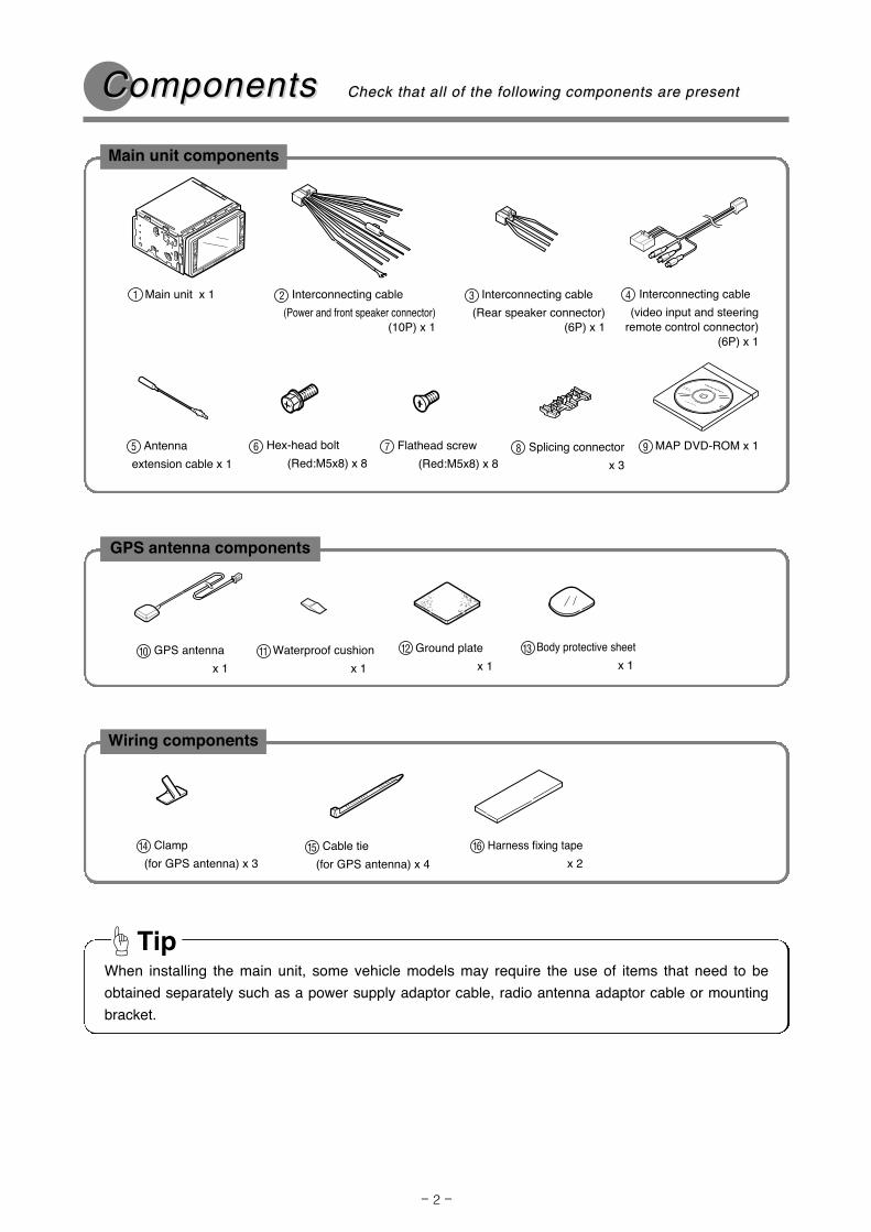
ComponentsComponents Check that all of the following components are present Check that all of the following components are present
GPS antenna components
MAP DVD-ROM x 19
GPS antenna
x 110 Waterproof cushion
x 111 Ground plate
x 1
12 Body protective sheet
x 113
Interconnecting cable
(Rear speaker connector)(6P) x 1
3Main unit x 11
Wiring components
Clamp
(for GPS antenna) x 3
14 Cable tie
(for GPS antenna) x 415 Harness fixing tape
x 2
16
When installing the main unit, some vehicle models may require the use of items that need to be
obtained separately such as a power supply adaptor cable, radio antenna adaptor cable or mounting
bracket.
Tip
Interconnecting cable
(Power and front speaker connector)(10P) x 1
2
Main unit components
Hex-head bolt
(Red:M5x8) x 86 Flathead screw
(Red:M5x8) x 8
7 Splicing connector
x 3
8Antenna
extension cable x 1
5
Interconnecting cable
(video input and steeringremote control connector)
(6P) x 1
4

- 3 -
Warnings and caution signs, illustrated bellow, are posted throughout this manual as well as on the
AVN5435. They show safe and correct ways to handle the product so as to prevent personal injury to you
and others and avoid damage to property.
Before reading through the manual, take time to read through and learn the important information listed in
this section.
This sign indicates a situation in which incorrect handling through disregard
of a sign might result in death or serious personal injury.
This sign indicates a situation in which incorrect handling through disregard of a sign
might result in personal injury or may result solely in damage to property.
FFor yor your safour safety in using the Aety in using the AVN5435VN5435
This section contains information that can help to prevent problems and
damage to the unit, and also contain other useful information.Tip
• Never supply power to another electrical appliance
by splicing or tapping into this product's power lead(wire). Otherwise, the current capacity of the wire willbe exceeded, resulting in a fire or electric shock.
• Never attempt to disassemble or modify the product.
Otherwise, an accident, fire or electric shock mayresult.
• When replacing fuses, be sure to use fuses of the
specified capacity (amperage). Otherwise, damageto the unit, fire or an electric shock may result.
• When installing the product into a vehicle with a
passenger side air bag, do not secure it to the airbag's cover or in places where it may impede air bagdeployment. Otherwise, proper air bag operation maynot be ensured in the event of an accident, causinginjury or death.
• When making holes using drill or similar tool, be sure
to wear protective eyewear. Otherwise, an injurysuch as loss of eyesight may result.
• Exposed wires must be insulated with electrical tape.
Otherwise, a short circuit, fire, or electric shock mayresult.
• Do not modify this system for use other than that
specified herein. Also, do not deviate from theinstallation procedures described herein; Eclipse willnot be held liable for damages including, but notlimited to serious injury, death or property damageresulting from installations that enable unintendedoperation.
• Do not install this product in locations where it may
obstruct the driver's view, or where it may endangerpassengers in the vehicle. Otherwise, an accident orinjury may result.
• Do not install this product in locations where it may
interfere with the operation of the steering wheel,shift lever, brake pedal, etc. Otherwise, an accidentor injury may result.
• To prevent damage to the vehicle, confirm the
locations of hoses, electrical wiring, and the fuel tankprior to drilling holes to install this product. Also, takecare so that the product does not interfere, nor comein contact with them. Otherwise, a fire may result.
• When installing this product, never use the existing
nuts or bolts that secure parts of the fuel tank, or thesteering or braking systems. Otherwise, impropersteering or braking or a fire may result.
• To prevent a short circuit from occurring, disconnect
the battery's negative terminal before installing thisproduct. Otherwise, an electric shock or injury mayresult.
• When using an existing nut and/or bolt from the
vehicle to ground this product, do not use any thatsecure parts of the steering or braking systems.Otherwise, an accident may result.
• Bundle cables and harnesses with electrical tape or
wire ties to prevent them from interfering with movingparts. If they should entangle with the steering wheel,shift lever or brake pedal, an accident may result.
- 4 -
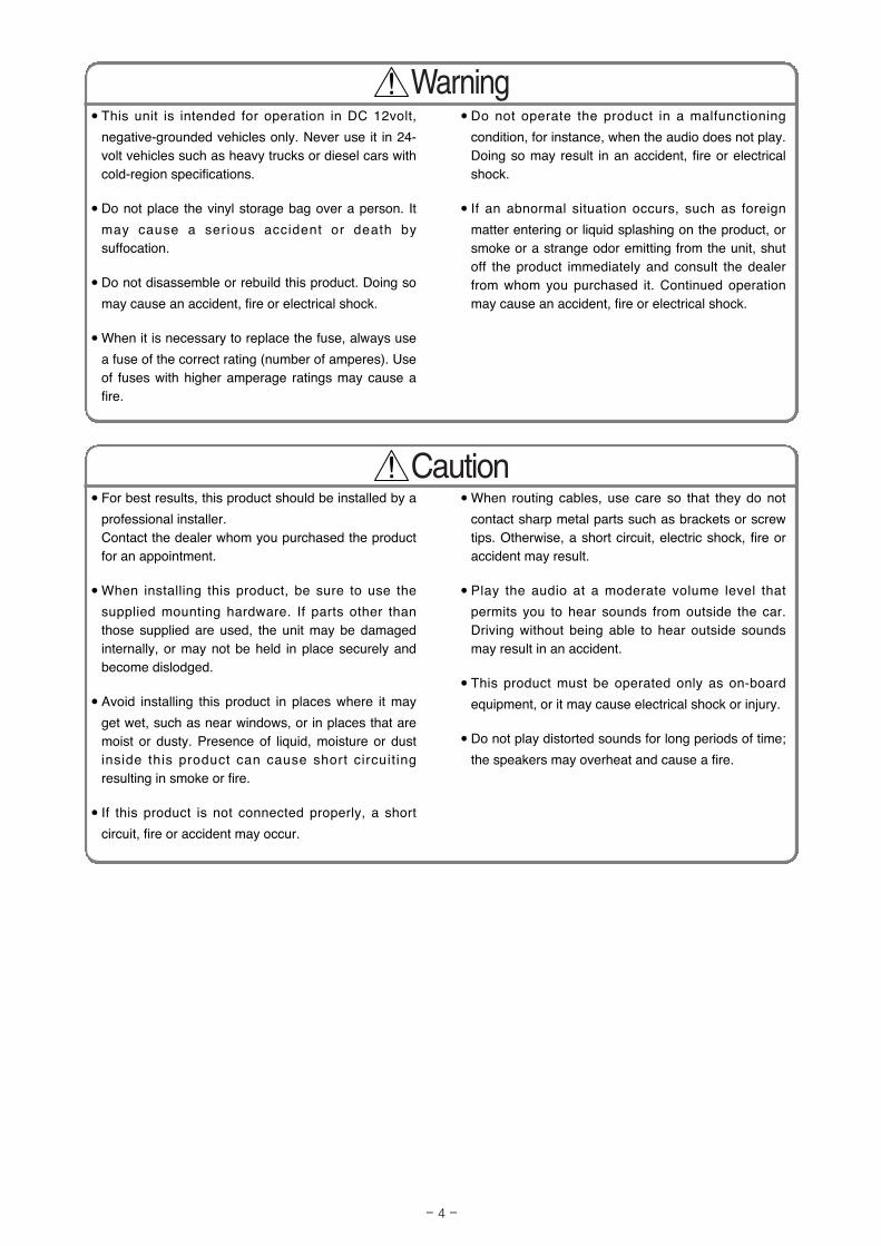
• When routing cables, use care so that they do not
contact sharp metal parts such as brackets or screwtips. Otherwise, a short circuit, electric shock, fire oraccident may result.
• Play the audio at a moderate volume level that
permits you to hear sounds from outside the car.Driving without being able to hear outside soundsmay result in an accident.
• This product must be operated only as on-board
equipment, or it may cause electrical shock or injury.
• Do not play distorted sounds for long periods of time;
the speakers may overheat and cause a fire.
• For best results, this product should be installed by a
professional installer. Contact the dealer whom you purchased the productfor an appointment.
• When installing this product, be sure to use the
supplied mounting hardware. If parts other thanthose supplied are used, the unit may be damagedinternally, or may not be held in place securely andbecome dislodged.
• Avoid installing this product in places where it may
get wet, such as near windows, or in places that aremoist or dusty. Presence of liquid, moisture or dustinside this product can cause short circuit ingresulting in smoke or fire.
• If this product is not connected properly, a short
circuit, fire or accident may occur.
• Do not operate the product in a malfunctioning
condition, for instance, when the audio does not play.Doing so may result in an accident, fire or electricalshock.
• If an abnormal situation occurs, such as foreign
matter entering or liquid splashing on the product, orsmoke or a strange odor emitting from the unit, shutoff the product immediately and consult the dealerfrom whom you purchased it. Continued operationmay cause an accident, fire or electrical shock.
• This unit is intended for operation in DC 12volt,
negative-grounded vehicles only. Never use it in 24-volt vehicles such as heavy trucks or diesel cars withcold-region specifications.
• Do not place the vinyl storage bag over a person. It
may cause a serious accident or death bysuffocation.
• Do not disassemble or rebuild this product. Doing so
may cause an accident, fire or electrical shock.
• When it is necessary to replace the fuse, always use
a fuse of the correct rating (number of amperes). Useof fuses with higher amperage ratings may cause afire.

- 5 -
Installation DiagInstallation Diagrramam
GPS antenna
(When installing inside the vehicle)
10
GPS antenna
(When installing outside the vehicle)
10
• If installing the GPS antenna inside the vehicle, the location and the slope of the vehicle's windshieldwill determine the accuracy of the GPS antenna to receive the GPS signal. If this occurs you may wantto install the antenna outside of the vehicle.
• The materials used in front and rear vehicle windows can cause GPS reception sensitivity to dropsignificantly. If this happens, install the GPS antenna on the outside of the vehicle.
Tip
Tip
Main unit1

- 6 -
Names and functions of terNames and functions of terminalsminals
• Never cut the insulation on the power cable or use it to power any other equipment. If the rated current
capacity of the power cable is exceeded, fire and electric shocks may result.
• The cables should be secured with tape or similar so that they will not cause an obstruction while
driving. If they get wound around components such as the steering wheel, shifting lever or brake pedal,
accidents may result.
• Refer to page 7 for details on the wire colors and connection points for interconnecting cables , and
and .
• Refer to page 8 for details on connection points , , , , , and
for the main unit cables and terminals.
43
2
Tip
A B C D E H
1
2
3
4
5 6P13P
Antenna extension cableBe sure to use when connectingthe radio antenna to the vehicleif the oem antenna cable is tooshort.
5
GPS ANTENNA10
9
10P
A
6
7
8
10
11
12
G
F
E
D
C
H
ANTENNA PLUG
MAIN UNIT
6P
1
INTERCONNECTING CABLE(Video input connector)
4
INTERCONNECTING CABLE(Rear speaker connector)
3
INTERCONNECTINGCABLE(Power and front speaker connector)
2
B

- 7 -
B+ (Yellow)Connect where power is constantly available, regardless of the ignition key's position.
ACC (Red)Connect where the power comes on when the ignition is in the ACC position.
Illumination power supply (Orange/White)Connect to where power comes on when the vehicle light switch is turned on.
Antenna power supply (Blue)
Connect to the automatic-antenna control terminal of the vehicle.
Control power supply (Blue/White)Connect the control terminal for the external amplifier, etc.
Front speaker output leadsConnect to the front speakers. White: Left + White/black: Left -
Gray: Right + Gray/Black: Right -
Rear speaker output leadsConnect to the rear speakers. Green: Left + Green/black: Left -
Purple: Right + Purple/Black: Right -
Ground (Black)Connect where good body grounding is available.
Genuine steering remote control terminalConnect to the vehicle steering remote control.
※Compatible vehicle models for installation : Vehicles with voltage detection-type steering remote control.
Ask your dealer for details.
VCR external input terminal (6P)Connect to the output cable of external video equipment such as a VCR.
8
7
6
5
4
3
2
1
Wire colors and connection points for connection cables and and 432
Never connect the power supply to the speaker leads (No.6 and No.7),
otherwise it will cause damage to the main unit.Caution
F
G

- 8 -
ACC ON/OFF power supply terminal (blue/white)If you use this terminal to connect equipment such as an external amplifier, you can still hear the audio guidance
from the navigation system even when audio is turned off. Connect it to the control terminal for the external
amplifier or other equipment.
※ A popping noise may be heard when the engine is being started or the ignition switch is at the ON position, but
this is normal and is not the sign of a malfunction.
Vehicle speed pulse signal terminal (Purple/White)
Connect to the vehicle speed pulse signal terminal.
Parking brake signal (Red/White)Connect to the parking brake signal terminal.
Reverse signal Wire (Green)Connect the reverse signal output of the vehicle to this terminal.
E-LAN terminal (13P)Connect to the E-LAN terminal of the CD changer, etc.
VIDEO OUT terminal (Yellow)Connect to an external monitor with video input.
Front line-out terminalConnect to the RCA connector of an external amplifier.
Rear line-out terminalConnect to the RCA connector of an external amplifier.
Line-out terminal (Non fader)This is used for non fader output. It can be used as a sub-woofer terminal if a separate amplifier with
a low bass filter is connected.
Back-eye camera external input terminal (4P)Used with the Eclipse back-eye camera (sold separately).
12
11
10
9
A
B
D
E
H
Main unit connections
C

- 9 -
Vehicle component adapter cable
Vehicle harness
From main unit
- Example of using vehicle adapter cables -
- Vehicle connections -
• You will need to purchase the necessary component adapter cable for the vehicle so that the power
supplies can be utilized. (Contact the dealer for further details.)
• Be sure to wrap the connection cables with plastic tape to insulate them.
Tip

- 10 -
Notes on installation
• Check the vehicle speed pulse signal, parking brake signal and reverse signal carefully before making
the connections. If the cables are incorrectly connected, accidents or problems with correct operation
may result.
• The label on the vehicle speed pulse signal cable contains a protection circuit, so do not cut the cable
or remove the protective circuit, otherwise problems with operation may result.
• Bind the cables together with tape so that they do not cause an obstruction while driving. If they
become wound around parts such as the steering wheel, shifting lever or brake pedal, accidents may
result.
The locations where the vehicle speed pulse signal cable, parking brake signal cable and reverse cable
come out vary depending on the vehicle model and grade. Ask the place of car dealer or your nearest
Eclipse dealer for details.
Tip
Connecting the vConnecting the vehicle speed pulse signal,ehicle speed pulse signal,
parparking brking brakake cabe cable and rele and revverse caberse cablele
- An example for connecting the vehicle speed pulse signal cable -
Use a splicing connector to connect the vehicle
speed pulse signal cable (purple/white) coming
from the main unit to the vehicle speed pulse
signal cable of the vehicle.
1
Route the vehicle speed pulse signal cable to the
main unit.2
Vehicle speed pulsesignal cable (vehicle harness) Engine computer
Vehicle speed pulsesignal cable(purple/white) ofconnection cable
Contain a protective circuit so
never remove.
Splicing connector8
Always be sure to connect the vehicle speed
pulse, otherwise the measurement precision will
be greatly reduced.
Tip

- 11 -
Foot-operatedParking brake
Parking brakeSignal Cable
Hand-operatedParking brake
- An example for connecting the parking brake signal -
Use a splicing connector to connect the parking
brake signal cable (red/white) coming from the
main unit to the parking brake signal cable of the
vehicle.
1
Route the parking brake signal cable to the main
unit.2
Position to attacha splicing connector
Parking brakesignal cable
Position to attacha splicing connector
Reverse signal cable
Reverse lamp
Reverse signal cable
- An example for connecting the reverse signal cable -
Use a splicing connector to connect the reverse
signal cable (green) coming from the main unit to
the reverse signal cable of the vehicle.
1
Route the reverse signal cable to the main unit .2
• Be sure to connect the reverse signal cable. If it is
not connected, the vehicle position may be
incorrect when the vehicle is reversed.
• Use a circuit tester to confirm that a sensing
voltage of 6 V or higher is generated when the
vehicle is reversed.
Tip

- 12 -
- Using the splicing connector -
Insert the connection cable [vehicle speed pulse
signal cable (purple/white), parking brake signal
cable (red/white) or reverse signal cable (green)]
from the main unit and the vehicle cable into the
splicing connector.
1
Push in the terminal (the metal part) of the
splicing connector using a pair of pliers.2
Harness in the car
Vehicle speed pulse signal cable(purple/white), parking brake cable(red/white) or reverse cable (green)
Splicing connector8
Press down the cover of the splicing connector
and squeeze it until it locks.3
Lock
Splicing connector8

- 13 -
System connection eSystem connection examplexample
• Never cut the insulation on the power cable or use it to power any other equipment. If the rated current
capacity of the power cable is exceeded, fire and electric shocks may result.
• The cables should be secured with tape or similar item so it will not cause an obstruction while driving.
If they get wound around components such as the steering wheel, shifting lever or brake pedal,
accidents may result.
• Install and connect all of the peripheral units before connecting them to the main unit.
• Do not remove the caps of pin jacks unless in use.
• Be sure to wrap the connection cables with plastic tape to insulate them.
Tip
DIN CABLE(Supplied with CD changer)Black
TO GROUND
TO BATTERY+12V(Permanent Supply)
Yellow
POWER CONNECTOR CABLE(Supplied with CD changer)
REARSPEAKERS
TO VEHICLE SPEED PULSE SIGNAL
TERMINAL (Refer to
page 9)
Purple/WhiteTO PARKING BRAKE
SIGNAL (Refer to
page 10)
Red/White
TO REVERSE SIGNAL
(Refer to page 10)
Green
TO BATTERY+12V
(Permanent Supply)
Yellow
TO ACC (Power Supply)
Red
TO HEAD LIGHT SWITCH (Illumination)
Orange/White
TO POWER ANTENNA RELAY (Supply)
Blue
TO TURN-ON LEAD OF EACH UNIT (Supply)Blue/W
hite
FRONTSPEAKERS
Black
TO GROUND
INTERCONNECTINGCABLE(Power and front speaker connector)
2INTERCONNECTING CABLE(Rear speaker connector)
3
TO MONITOR
FRONTREARNON FADER (remove covers when using external amplifier)
TO STEERING REMOTECONTROL
GPS ANTENNA10
ANTENNA EXTENSION CABLEBe sure to use when connecting theradio antenna to the vehicle.
5
ANTENNAPLUG
INTERCONNECTING CABLE(Video input connector)
4
FROM EXTERNAL VIDEO EQUIPMENTMAIN UNIT1
BEC104(sold separately)
YellowWhite
Red
NOCONNECTION
CH3083(sold separately)
13P
4P
6P
1P
10P
6P
13P
2P

- 14 -
Tip
Installing the GPS antennaInstalling the GPS antenna
Notes on installation
• The GPS antenna should be installed in a level
position where the signals will be as unobscured asmuch as possible, such as on the vehicle's roof.Satellite signals cannot be received if the antenna isobscured.
• If installing the GPS antenna outside the vehicle,
remove the main antenna unit if leaving the vehicleunattended for long periods in order to prevent theftor malicious damage to the antenna.
• Hold the main antenna unit when removing the
antenna. Do not pull on the cable, otherwise it maybecome damaged and result in problems with correctoperation.
• If installing the GPS antenna outside the vehicle,
remove the main antenna unit when washing thevehicle. (If you wash the vehicle with the mainantenna unit still attached, avoid spraying the cablesection directly with water so that no water getsinside the vehicle.)
• The magnet that is attached to the GPS antenna is
extremely strong. Be sure to note the following wheninstalling the antenna.
• Do not put the antenna down on the ground or ondirty or dusty surfaces. If iron filings becomeattached to the magnet, they may cause damageto the vehicle's body.
• Keep the antenna away from watches andmagnetic cards, otherwise they may be damagedand/or rendered unusable.
• If installing the GPS antenna inside the vehicle, be
sure it is mounted to the ground plate.
• If installing the GPS antenna inside the vehicle, the
location and the slope of the vehicle's windshield willdetermine the accuracy of the GPS antenna toreceive the GPS signal. If this occurs you may wantto install the antenna outside of the vehicle.
• The materials used in front and rear vehicle windows
can cause GPS reception sensit ivity to dropsignificantly. If this happens, install the GPS antennaon the outside of the vehicle.
• If the attachment surface is a non-plastic surface
such as genuine leather, wood panel or cloth,attaching the antenna may damage the surfacefinish. Do not attach the ground plate to suchsurfaces.
• Wipe the installation surface thoroughly so that it is
clear of any dirt, moisture or grease before installingthe antenna.
• Do not apply any coatings to the GPS antenna,
otherwise it may cause a drop in the receptionsensitivity of the antenna.
• Route the GPS antenna cable as far away as
possible from TV and radio antennas and cables,otherwise it may cause interference with video andaudio signals.
• Do not install the antenna in places (such as front
pillars and roof panel) that are shielded from the sky.
• The cables should be bound together with tape or similar so that they do not interfere with driving. If it
becomes wound around parts such as the steering wheel, shifting lever or brake pedal, accidents may
result.
• Do not install the GPS antenna where it will obstruct the driver's vision or where it will be an obstacle
while driving, otherwise traffic accidents may result.

- 15 -
- Installation inside the vehicle (example) -
Choose an installation location on the dashboard
which is flat and has a clear view of the sky.1
Install the ground plate to the dashboard.2
Install the GPS antenna to the ground plate.3
Ground plate12
Secure the GPS antenna cable with clamps.4
Route the GPS antenna cable along the crevice
between the front windshield and the dashboard.5
Route the GPS antenna to the main unit
installation position.6
Harness fixing tape16
GPS antenna10
Front of vehicle
Front of vehicle
TapeGPS antenna10
Clamp(metal)
14
Clamp14
GPS antenna cable10
Select a location that is at least 19.68 in. away
from the main unit. If this is not done, the GPS
measurement precision will drop.
Tip
If the GPS antenna cable protrudes from the
dashboard, wind tape around it so that it stays
securely fixed in the crevice between the front
windshield and the dashboard.
Tip
If installing the GPS antenna inside the vehicle, the installation location and the shape of the vehicle's
body determine GPS accuracy. Accuracy is usually lower when the GPS antenna is installed inside
the vehicle.
Tip
Cut the harness fixing tape into usable lengths
with scissors. Do the same for the rest of the
installation.
Tip
Tip
Tip

- 16 -
- Installation outside the vehicle (example) -
Choose an installation location where the GPS
antenna can be attached securely.1
Remove the backing paper from the body
protective sheet and attach the sheet to the
vehicle.
2
Install the GPS antenna on top of the body
protective sheet.3
Body protectivesheet (clear)
13
Route the GPS antenna cable to the main unit
while securing it with harness fixing tape.7
Harness fixing tape16
GPS antenna10
Front of vehicle
Route the GPS antenna cable inside the vehicle's
trunk and secure it with clamps.4
Attach the waterproof cushion so that the GPS
antenna cable is flat against the weatherstrip
when the trunk lid is closed.
5
Route the GPS antenna cable while securing it
with cable ties.6
Cable tie(long)
15
Waterproof cushion
Front of vehicle
Front of vehicle
Weatherstrip
Route tomain unit
Clamp(metal)
1411
Apply plain water or soapy water to the
waterproof cushion when moving it.
Tip
Cut the harness fixing tape into usable lengths
with scissors. Do the same for the rest of the
installation.
Tip

- 17 -
Installing the main unitInstalling the main unit
Remove the pocket and any other accessories
from the center cluster to make room for the main
unit.
1
Remove the mounting brackets for the pocket.2
30˚ or less
Level (reference)
Front
- Installation angle -
Mounting bolts
Pocket, etc
Center cluster panel
Attach the brackets to the main unit.3
Install the main unit in the vehicle.4
- Mounting the main unit (example)-
Main unit
Mounting bracket
Hex-head bolt(Red:M5 x 8) x 8
Hex-head bolt(Red:M5 x 8) x 8
Flatheadscrew(Red:M5x8) x 8
Select the screws in accordance with the shapesof the screw holes in the mounting bracket.
6 7
6
1
To maintain proper function, the unit must be
mounted less than 30 degrees. If the angle is in
excess of 30 degrees, DVD/CD skipping or
ejection may occur.
Tip
Connect all cables before installing the main
unit.
Tip
Be sure to use the accessory screws (M5x8) to
install.
Tip

- 18 -

- 19 -

- 20 -090003-281207000412DE (CN)
“ECLIPSE” is a registered trademark of FUJITSU TEN LIMITED in 48 countries
including the U.S. and Japan.
Top Related