


Languages
Pages
Legal

GA SeriesPackaged Terminal Air Conditioner / Heat Pump7,000 --- 15,000 Btuh
Installation and OperatingInstructions
UNIT INFORMATIONModel # ______________________________
Serial # ______________________________
INSTALLATION INFORMATIONDate Installed __________________________
DEALERSHIP CONTACT INFORMATIONCompany Name: __________________________________
Address: _________________________________________
_________________________________________________
Phone Number: ________________________________
Technician Name: _________________________________
_________________________________________________
NOTE TO EQUIPMENT OWNER:
Thank you for purchasing a Gree PTAC. Please read this Owner’s Information Manual carefully before installing and using this appliance. Keep this manual for future reference.
For your convenience, please record the model and serial numbers of your new equipment in the spaces provided. This information, along with the installation data and dealer contact information, will be helpful should your system require maintenance or service.

2
UNIT INSPECTIONExamine unit for damage incurred during shipment. File a claim immediately with the transitcompany if damage is found.
TABLE OF CONTENTSPAGE
SAFETY CONSIDERATIONS 3. . . . . . . . . . . . . . . . . . . . . . . . . . . . . . . . . . . . . . . . . . . . . . . . . . . . . . . . . . . . . . . . . . . . . . . . . . .
GENERAL INFORMATION. 3. . . . . . . . . . . . . . . . . . . . . . . . . . . . . . . . . . . . . . . . . . . . . . . . . . . . . . . . . . . . . . . . . . . . . . . . . . . .
UNIT FEATURES 4 -- 5. . . . . . . . . . . . . . . . . . . . . . . . . . . . . . . . . . . . . . . . . . . . . . . . . . . . . . . . . . . . . . . . . . . . . . . . . . . . . . . . . .
ELECTRICAL DATA 6. . . . . . . . . . . . . . . . . . . . . . . . . . . . . . . . . . . . . . . . . . . . . . . . . . . . . . . . . . . . . . . . . . . . . . . . . . . . . . . . . .
INSTALLATION
Chassis Installation 7. . . . . . . . . . . . . . . . . . . . . . . . . . . . . . . . . . . . . . . . . . . . . . . . . . . . . . . . . . . . . . . . . . . . . . . . . . . . .
Retrofit Sleeve Preparation 8. . . . . . . . . . . . . . . . . . . . . . . . . . . . . . . . . . . . . . . . . . . . . . . . . . . . . . . . . . . . . . . . . . . . . . .
8Installation of Gree Wall Sleeve Using Non-Gree Grille . . . . . . . . . . . . . . . . . . . . . . . . . . . . . . . . . . . . . . . . . . . . . . . . .
Install Unit Into Wall Sleeve 9. . . . . . . . . . . . . . . . . . . . . . . . . . . . . . . . . . . . . . . . . . . . . . . . . . . . . . . . . . . . . . . . . . . . . .
HOW TO CONNECT 10. . . . . . . . . . . . . . . . . . . . . . . . . . . . . . . . . . . . . . . . . . . . . . . . . . . . . . . . . . . . . . . . . . . . . . . . . . . . . . . . . .
SYSTEM CONFIGURATION
Ventilation Control 11. . . . . . . . . . . . . . . . . . . . . . . . . . . . . . . . . . . . . . . . . . . . . . . . . . . . . . . . . . . . . . . . . . . . . . . . . . . .
Adjusting Air Direction 11. . . . . . . . . . . . . . . . . . . . . . . . . . . . . . . . . . . . . . . . . . . . . . . . . . . . . . . . . . . . . . . . . . . . . . . . .
Dipswitches 12. . . . . . . . . . . . . . . . . . . . . . . . . . . . . . . . . . . . . . . . . . . . . . . . . . . . . . . . . . . . . . . . . . . . . . . . . . . . . . . . . .
Keypad Configuration 13. . . . . . . . . . . . . . . . . . . . . . . . . . . . . . . . . . . . . . . . . . . . . . . . . . . . . . . . . . . . . . . . . . . . . . . . . .
AUXILIARY CONTROLS
Wall Thermostat Terminal 14 -- 15. . . . . . . . . . . . . . . . . . . . . . . . . . . . . . . . . . . . . . . . . . . . . . . . . . . . . . . . . . . . . . . . . . .
Energy Management Input 15. . . . . . . . . . . . . . . . . . . . . . . . . . . . . . . . . . . . . . . . . . . . . . . . . . . . . . . . . . . . . . . . . . . . . .
Intelligent Self--Checking Control 15. . . . . . . . . . . . . . . . . . . . . . . . . . . . . . . . . . . . . . . . . . . . . . . . . . . . . . . . . . . . . . . . .
OPERATION 16. . . . . . . . . . . . . . . . . . . . . . . . . . . . . . . . . . . . . . . . . . . . . . . . . . . . . . . . . . . . . . . . . . . . . . . . . . . . . . . . . . . . . . . .
CARE AND CLEANING 17. . . . . . . . . . . . . . . . . . . . . . . . . . . . . . . . . . . . . . . . . . . . . . . . . . . . . . . . . . . . . . . . . . . . . . . . . . . . . . .
PREVENTATIVE MAINTENANCE 18. . . . . . . . . . . . . . . . . . . . . . . . . . . . . . . . . . . . . . . . . . . . . . . . . . . . . . . . . . . . . . . . . . . . . .
TROUBLESHOOTING 19. . . . . . . . . . . . . . . . . . . . . . . . . . . . . . . . . . . . . . . . . . . . . . . . . . . . . . . . . . . . . . . . . . . . . . . . . . . . . . . .
WARRANTY 23 -- 24. . . . . . . . . . . . . . . . . . . . . . . . . . . . . . . . . . . . . . . . . . . . . . . . . . . . . . . . . . . . . . . . . . . . . . . . . . . . . . . . . . . . .
NOTE: Warranty coverage documented on back page of owners manual
3
READ ALL INSTRUCTIONS BEFORE INSTALLATION OR USE
SAFETY CONSIDERATIONSRecognize safety information. This is the safety--alertsymbol . When you see this symbol on the unit andin instructions or manuals, be alert to the potential forpersonal injury.Understand these signal words: DANGER,WARNING, and CAUTION. These words are usedwith the safety--alert symbol. DANGER identifies themost serious hazards which will result in severepersonal injury ordeath. WARNINGsignifieshazardswhich could result in personal injury or death.CAUTION is used to identify unsafe practices whichmay result in minor personal injury or product andproperty damage. NOTE is used to highlightsuggestions which will result in enhancedinstallation, reliability, or operation.
PERSONAL INJURY AND/OR PROPERTY DAMAGEHAZARD
Failure to follow this warning could result in personal injury,death and/or property damage.
For your safety, the information in this manual must befollowed to minimize the risk of fire or explosion, electricshock, or to prevent property damage, personal injury, or lossof life.
• This unit must be properly installed in accordancewith the Installation Instructions before it is used.
• Immediately repair or replace all electric servicecords that have become frayed or otherwisedamaged.
• Unplug or disconnect the unit at the fuse box orcircuit breaker before making any repairs.
! WARNING
NOTE: We strongly recommend that any servicingbe performed by a qualified individual.
GENERAL
BEFORE YOU BEGINRead these instructions completely and carefully.
IMPORTANT: Save these instructions for localinspector’s use.IMPORTANT: Observe all governing codes andordinances.
NOTE TO INSTALLERBe sure to leave these instructions with the owner.
NOTE TO OWNERKeep these instructions for future reference. Be sureto write down the model and serial number of unit onspace provided on front page. The model and serialnumber can be located on the serial number plateattached to unit.
Save the wall thermostat control panel label to beplaced on control panel in case a wall thermostat isused or is added in the future. (See Fig. 23)
Thank you for choosing the Gree PTAC! You can feel confident in your selection because of the pride in craftsmanship and engineering knowledge that goes into this equipmentt.Gree package terminal air conditioners and heat pumps provide a high standard of quality in performance, workmanship, durability and appearance as they heat and cool the occupied air space year round.This manual provides information for ease of installation, operation and maintenance.All models are designed for through-the-wall installation. Separate installation instructions are included with all accessory components.
4
UNIT FEATURES
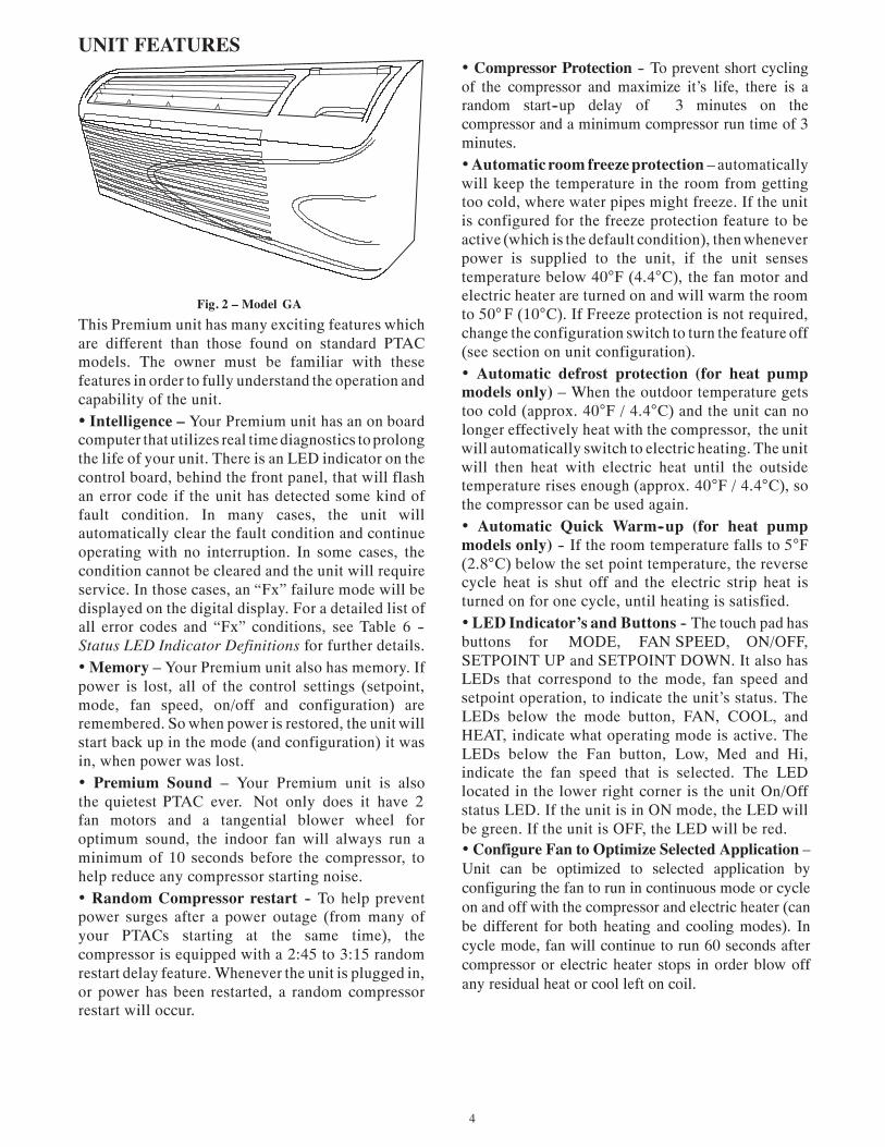
Fig. 2 – Model GAThis Premium unit has many exciting features whichare different than those found on standard PTACmodels. The owner must be familiar with thesefeatures in order to fully understand the operation andcapability of the unit.• Intelligence – Your Premium unit has an on boardcomputer that utilizes real timediagnostics to prolongthe life of your unit. There is an LED indicator on thecontrol board, behind the front panel, that will flashan error code if the unit has detected some kind offault condition. In many cases, the unit willautomatically clear the fault condition and continueoperating with no interruption. In some cases, thecondition cannot be cleared and the unit will requireservice. In those cases, an “Fx” failure mode will bedisplayed on the digital display. For a detailed list ofall error codes and “Fx” conditions, see Table 6 --Status LED Indicator Definitions for further details.• Memory – Your Premium unit also has memory. Ifpower is lost, all of the control settings (setpoint,mode, fan speed, on/off and configuration) areremembered. So when power is restored, the unit willstart back up in the mode (and configuration) it wasin, when power was lost.• Premium Sound – Your Premium unit is alsothe quietest PTAC ever. Not only does it have 2fan motors and a tangential blower wheel foroptimum sound, the indoor fan will always run aminimum of 10 seconds before the compressor, tohelp reduce any compressor starting noise.• Random Compressor restart -- To help preventpower surges after a power outage (from many ofyour PTACs starting at the same time), thecompressor is equipped with a 2:45 to 3:15 randomrestart delay feature. Whenever the unit is plugged in,or power has been restarted, a random compressorrestart will occur.
• Compressor Protection -- To prevent short cyclingof the compressor and maximize it’s life, there is arandom start--up delay of 3 minutes on thecompressor and a minimum compressor run time of 3minutes.•Automatic room freeze protection – automaticallywill keep the temperature in the room from gettingtoo cold, where water pipes might freeze. If the unitis configured for the freeze protection feature to beactive (which is the default condition), then wheneverpower is supplied to the unit, if the unit sensestemperature below 40°F (4.4°C), the fan motor andelectric heater are turned on and will warm the roomto 50°F (10°C). If Freeze protection is not required,change the configuration switch to turn the feature off(see section on unit configuration).• Automatic defrost protection (for heat pumpmodels only) – When the outdoor temperature getstoo cold (approx. 40°F / 4.4°C) and the unit can nolonger effectively heat with the compressor, the unitwill automatically switch to electric heating. The unitwill then heat with electric heat until the outsidetemperature rises enough (approx. 40°F / 4.4°C), sothe compressor can be used again.• Automatic Quick Warm--up (for heat pumpmodels only) -- If the room temperature falls to 5°F(2.8°C) below the set point temperature, the reversecycle heat is shut off and the electric strip heat isturned on for one cycle, until heating is satisfied.• LED Indicator’s and Buttons -- The touch pad hasbuttons for MODE, FAN SPEED, ON/OFF,SETPOINT UP and SETPOINT DOWN. It also hasLEDs that correspond to the mode, fan speed andsetpoint operation, to indicate the unit’s status. TheLEDs below the mode button, FAN, COOL, andHEAT, indicate what operating mode is active. TheLEDs below the Fan button, Low, Med and Hi,indicate the fan speed that is selected. The LEDlocated in the lower right corner is the unit On/Offstatus LED. If the unit is in ON mode, the LED willbe green. If the unit is OFF, the LED will be red.• Configure Fan to Optimize Selected Application – Unit can be optimized to selected application by configuring the fan to run in continuous mode or cycle on and off with the compressor and electric heater (can be different for both heating and cooling modes). In cycle mode, fan will continue to run 60 seconds after compressor or electric heater stops in order blow off any residual heat or cool left on coil.
5
UNIT FEATURES CONTINUED
• Unit Configuration – There are many differentconfiguration possibilities, through both dipswitchesand the digital keypad, that allow you to configurethe unit for your exact application. See section onunit configuration for more details. Following are theconfiguration selections that havenot previouslybeenmentioned:• ˚F or ˚C – The unit can display in either ˚F or ˚C• Indoor Temperature Sensor Biasing – Optimizethe room temperature sensor reading to your exactapplication (one for cooling and another for heating)..• Emergency Heat (for Heat Pump Only) – Disablethe compressor during heating mode operation (heatonly with Electric Heat).• Display Setpoint OR Room Temperature -- Theunit can be configured to display the roomtemperature OR setpoint only, during heating andcooling modes. See section on unit configuration formore details.
• Limit the Setpoint Range -- The unit can beconfigured to limit the controlling setpoint range. Thedisplay will always show the complete setpoint range,but the controlling setpoint will be limited to theconfiguredminimumandmaximumsetpointselected.See section on unit configuration for more details.• Energy Management – Sometimes known asFront Desk Control, an input is provided so that theunit can be manually disabled from a differentlocation. If the unit detects 24vac on this input, it willautomatically turn itself off. If no voltage is detectedon the input, the unit will run normally.• Wall Thermostat Control – A wired wallthermostat can be connected to the unit. If it is, theunit must be configured to disable the keypad. Seesection on wired inputs and unit configuration formore details.
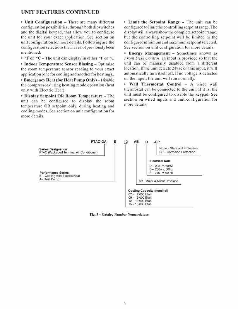
Fig. 3 – Catalog Number Nomenclature
Cooling Capacity (nominal)07 – 7,000 Btuh09 – 9,000 Btuh12 – 12,000 Btuh15 – 15,000 Btuh
PTAC-GA E 12 AB D
Series DesignationPTAC (Packaged Terminal Air Conditioner)
Performance SeriesE – Cooling with Electric HeatA– Heat Pump
Electrical Data
D--- 208---v, 60HZD--- 230---v, 60HzP--- 265---v, 60 Hz
-CP
None – Standard ProtectionCP – Corrosion Protection
AB - Major & Minor Revsions

6
ELECTRICAL DATA
ELECTRICAL SHOCK HAZARDFailure to follow this warning could result in personalinjury or death and/or property damage
DO NOT alter cord or plug or use an extension cord.
! WARNING
POWER CONNECTION OPTIONSAppropriate power cord accessory kit is determinedby the voltage, and amperage of the branch circuit.The unit does not come with a power cord (orhard wire kit). An accessory power cord kit mustbe ordered to connect the unit to the outlet. If theunit is to be hard wired, an accessory hard wire kitmust be ordered.
EQUIPMENT DAMAGE HAZARDFailure to follow this caution may result in equipmentdamage or improper operation.Using a 30 amp cord on --U07 and --U09 models couldresult in damage the unit. For these models, use 15 or 20amp power cords only.
CAUTION!
IMPORTANT: For 265V units, if power cord
long and must plug into the accessory electrical265V subbase.Be sure that your outlet matches the appropriate bladeconfiguration of the plug and that it is within reach ofthe service cord.All wiring, including installation of the receptacle,must be in accordance with the NEC and local codes,ordinances and regulations. National codes requirethe use of an arc fault or leakage current detectiondevice on all 208/230V power cords. Be sure to selectthe correct cord for your installation.
ALL UNITSWire SizeUse recommended wire size given in Table 1 andinstall a single branch circuit. All wiring mustcomply with local and national codes. All units are
designed to operate off ONE single branch circuitsonly.NOTE: Use copper conductors only.Table 1—SUGGESTED BRANCH CIRCUIT WIRE SIZES*
NAMEPLATE AMPS AWG WIRE SIZE†
7.0 to 12 14
12.1 to 16 12
16.1 to 24 10LEGENDAWG --- American Wire Gauge* Single circuit from main box.† Based on copper wire at 60˚C temperature rating.
GroundingFor safety and protection, the unit is groundedthrough the service cord plug or through separateground wire provided on hard wired units. Be surethat the branch circuit or general purpose outlet isgrounded.
VOLTAGE SUPPLYCheck voltage supply at outlet. For satisfactoryresults, the voltage range must always be within theranges found on the data information plate.Cord--connected UnitsThe 250--v field supplied outlet must match the plugfor the standard 208/230--v units and be within reachof the service cord. The standard cord--connected265--v units require an accessory electrical subbasefor operation. Refer to Table 2 for proper receptacleand fuse type.Power Cord ProtectionThe power cord for 208/230v units provide powercord fire protection. Unit power automaticallydisconnects when unsafe conditions are detected.Power to the unit can be restored by pressing the resetbutton on plug head.Upon completion of unit installation for 208/230Vmodels, an operational check should be performedusing the TEST/RESET buttons on the plug head.NOTE: The 265v models do not incorporate thisfeature as they require use of the electrical subbaseaccessory.
Table 2—RECEPTACLES AND FUSE TYPES -- 250, 265 VOLTS
RECEPTACLE
AMPS 15 20 30 15 20 30
RATED VOLTS 250 250 250 265 265 265
Power Cord Part Number PWRCORD-230V-15A PWRCORD-230V-20A PWRCORD-230V-30A PWRCORD-265V-15A PWRCORD-265V-20A PWRCORD-265V-30 A
TIME---DELAY TYPE FUSE (orHACR Circuit Breaker) 15 20* 30 15 20 30
LEGENDHACR --- Heating, Air Conditioning, Refrigeration* May be used for 15---amp applications if fused for 15 amps.
accessory option is selected, the cord is only 18 inches
7
INSTALLATION
Proper installation is the responsibility of theinstaller.Product failure due to improper installation is notcovered under the Warranty.
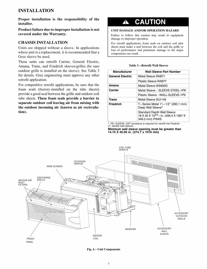
CHASSIS INSTALLATIONUnits are shipped without a sleeve. In applicationswhere unit is a replacement, it is recommended that aGree sleeve be used.
UNIT DAMAGE AND/OR OPERATION HAZARDFailure to follow this caution may result in equipmentdamage or improper operation.
For retrofit applications, foam seals on outdoor coil tubesheets must make a seal between the coil and the grille orloss of performance and premature damage to the majorcomponents can result.
CAUTION!
Table 3—Retrofit Wall Sleeves
Manufacturer Wall Sleeve Part Number
General Electric Metal Sleeve RAB71
Plastic Sleeve RAB77Amana MCarrier
etal Sleeve WS900D
Metal Sleeve – SLEEVE-STEEL-1PK
Plastic Sleeve - WALL-SLEEVE-1PK
Trane Metal Sleeve SLV149
Friedrich T---Series Metal 11---1/2” (292.1 mm)Deep Wall Sleeve*
Standard Depth Wall Sleeve16 X 42 X 133/4--- in. (406.4 X 1067 X349.3 mm) PXWS
* FR---SLEEVE---EXT accessory is required for retrofit into Friedrich(T---Series) wall sleeves.Minimum wall sleeve opening must be greater than14.75 X 40.00 in. (374.7 x 1016 mm)
FRONTPANEL
INDOORCOIL
BASEPAN
DISCHARGEGRILLE
WIRE SCREEN
OUTDOORORIFICE
COIL TUBESHEETS
INDOOR-AIRINLETFILTERS
ACCESSORY WALL
SLEEVE
ACCESSORY OUTDOOR
GRILLE
Fig. 4 – Unit Components
These units can retrofit Carrier, General Electric, Amana, Trane, and Friedrich sleeves/grilles (be sure outdoor grille is installed on the sleeve). See Table 3 for details. Gree engineering must approve any other retrofit application.For competitive retrofit applications, be sure that the foam seals (factory-installed on the tube sheets) provide a good seal between the grille and outdoor coil tube sheets. These foam seals provide a barrier to separate outdoor coil leaving air from mixing with the outdoor incoming air (known as air recircula-tion).
8
RETROFIT SLEEVE PREPARATIONIMPORTANT: Inspect wall sleeve thoroughlyprior to installation. Manufacturer does notassume responsibility for costs or damages due todefects in sleeve or for improper installation.
ELECTRICAL SHOCK HAZARDFailure to follow this warning could result in personal injuryor death.Disconnect all power to unit to avoid possible electrical shockduring installation.
! WARNING
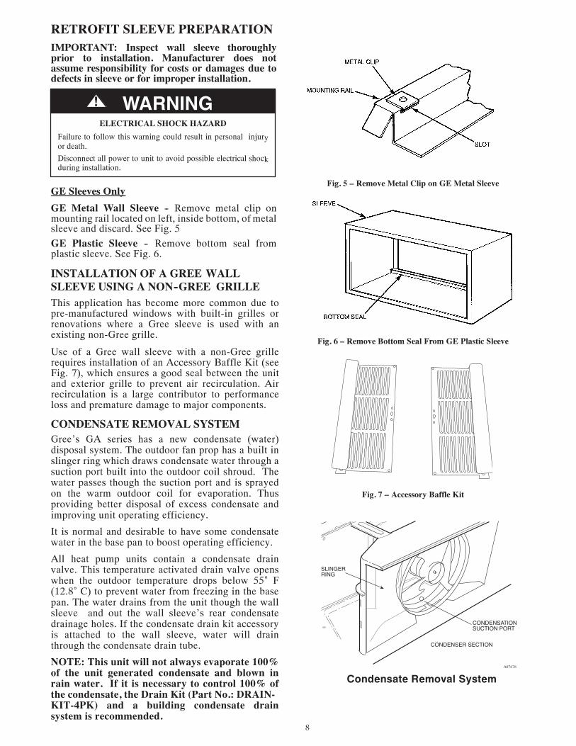
GE Sleeves OnlyGE Metal Wall Sleeve -- Remove metal clip onmounting rail located on left, inside bottom, of metalsleeve and discard. See Fig. 5GE Plastic Sleeve -- Remove bottom seal fromplastic sleeve. See Fig. 6.
INSTALLATION OF A GREE WALLSLEEVE USING A NON--GREE GRILLE
Fig. 5 – Remove Metal Clip on GE Metal Sleeve
Fig. 6 – Remove Bottom Seal From GE Plastic Sleeve
Fig. 7 – Accessory Baffle Kit
This application has become more common due to pre-manufactured windows with built-in grilles or renovations where a Gree sleeve is used with an existing non-Gree grille.
Use of a Gree wall sleeve with a non-Gree grille requires installation of an Accessory Baffle Kit (see Fig. 7), which ensures a good seal between the unit and exterior grille to prevent air recirculation. Air recirculation is a large contributor to performance loss and premature damage to major components.
CONDENSATE REMOVAL SYSTEMGree’s GA series has a new condensate (water) disposal system. The outdoor fan prop has a built in slinger ring which draws condensate water through a suction port built into the outdoor coil shroud. The water passes though the suction port and is sprayed on the warm outdoor coil for evaporation. Thus providing better disposal of excess condensate and improving unit operating efficiency.
It is normal and desirable to have some condensate water in the base pan to boost operating efficiency.
All heat pump units contain a condensate drain valve. This temperature activated drain valve opens when the outdoor temperature drops below 55˚ F (12.8˚ C) to prevent water from freezing in the base pan. The water drains from the unit though the wall sleeve and out the wall sleeve’s rear condensate drainage holes. If the condensate drain kit accessory is attached to the wall sleeve, water will drain through the condensate drain tube.
NOTE: This unit will not always evaporate 100% of the unit generated condensate and blown in rain water. If it is necessary to control 100% of the condensate, the Drain Kit (Part No.: DRAIN-KIT-4PK) and a building condensate drain system is recommended.
SLINGERRING
CONDENSER SECTION
CONDENSATIONSUCTION PORT
A07678
Condensate Removal System

9
INSTALL UNIT INTO WALL SLEEVE
1. Carefully remove shipping tape from the frontpanel and vent door. See Fig. 8.
2. Remove shipping screw from the vent door, ifpresent. See Fig. 9.
3. Remove front panel. See Fig. 10.4. Lift unit level and slide unit into wall sleeve
until foam seal rests firmly against front of wallsleeve.
5. Secure with four screws (supplied) through theunit flange holes. See Fig. 11.
6. Reinstall front panel. See Fig. 12.
PERSONAL INJURY HAZARDFailure to follow this warning could result in personalinjury or death.Chassis weighs up to 150 pounds (68.0 kg). Seek helpwhen lifting unit.Lift unit by holding unit basepan.
! WARNING
UNIT DAMAGE HAZARDFailure to follow this caution may result in equipmentdamage or improper operation.
Failure to remove shipping tape and screw will preventfresh air vent door from opening and may result in damageto vent door cable
CAUTION!
Shippingtape
Fig. 8 – Shipping Tape Location
Remove shippingscrew if present
Fig. 9 – Shipping Screw Location
Pull out at the bottom to release it from the tabs(1). Then lift up (2).
Fig. 10 – Removing Front Panel
Fig. 11 – Securing Unit
Place tabs over top rail (1). Push Inward atbottom until panel snaps into place (2).
Fig. 12 – Replacing Front Panel
10
HOW TO CONNECT
IMPORTANT: Please read following electricalsafety data carefully.
! WARNINGELECTRICAL SHOCK AND/OR UNIT OPERATION
AND DAMAGE HAZARDFailure to follow this warning could result in personal injuryor death and/or unit operation and damage.
• Follow the National Electrical Code (NEC) or localcodes and ordinances.
• For personal safety, this unit MUST BE properlygrounded.
• Protective devices (fuses or circuit breakers)acceptable for unit installations are specified on thenameplate of each unit.
• Do not use an extension cord with this unit.
• Aluminum building wiring may present specialproblems -- consult a qualified electrician.
• When unit is in STOP position, there is stillvoltage to electrical controls.
• Disconnect power to unit before servicing by:1. Removing power cord (if it has one) from wall
receptacle.2. Removing branch circuit fuses or turning circuit
breakers off at panel.
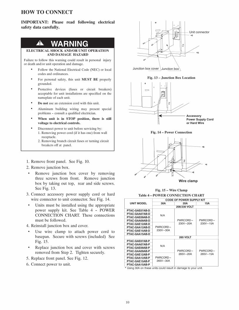
1. Remove front panel. See Fig. 10.2. Remove junction box.• Remove junction box cover by removing
three screws from front. Remove junctionbox by taking out top, rear and side screws.See Fig. 13.
3. Connect accessory power supply cord or hardwire connector to unit connector. See Fig. 14.
• Units must be installed using the appropriatepower supply kit. See Table 4 -- POWERCONNECTION CHART. These connectionsmust be followed.
4. Reinstall junction box and cover.• Use wire clamp to attach power cord to
basepan. Secure with screws (included) SeeFig. 15.
• Replace junction box and cover with screwsremoved from Step 2. Tighten securely.
5. Replace front panel. See Fig. 12.6. Connect power to unit.
Unit connector
Junction box cover Junction box
Fig. 13 – Junction Box Location
Accessory Power Supply Cordor Hard Wire
Fig. 14 – Power Connection
Wire clamp
Fig. 15 – Wire ClampTable 4—POWER CONNECTION CHART
UNIT MODELCODE OF POWER SUPPLY KIT
30A 20A 15A208/230 VOLT
PTAC-GAE07AB-DPTAC-GAA07AB-DPTAC-GAE09AB-DPTAC-GAA09AB-DPTAC-GAE12AB-DPTAC-GAA12AB-DPTAC-GAE15AB-DPTAC-GAA15AB-D
PTAC-GAE07AB-PPTAC-GAA07AB-PPTAC-GAE09AB-PPTAC-GAA09AB-PPTAC-GAE12AB-PPTAC-GAA12AB-PPTAC-GAE15AB-PPTAC-GAA15AB-P
N/A
PWRCORD---230V---20A
PWRCORD---230V---15A
PWRCORD---230V---30A
265 VOLT
N/A
PWRCORD---265V---20A
PWRCORD---265V---15A
PWRCORD---265V---30A
* Using 30A on these units could result in damage to your unit.
11
SYSTEM CONFIGURATION
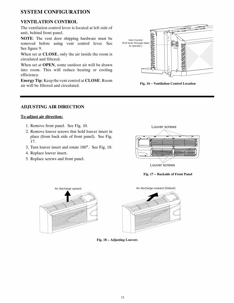
VENTILATION CONTROLThe ventilation control lever is located at left side ofunit, behind front panel.NOTE: The vent door shipping hardware must beremoved before using vent control lever. SeeSee figure 9.When set at CLOSE, only the air inside the room iscirculated and filtered.When set at OPEN, some outdoor air will be drawninto room. This will reduce heating or coolingefficiency.Energy Tip: Keep the vent control at CLOSE. Roomair will be filtered and circulated.
Open
Close
Vent Control (Pull lever through label
to operate.)
Fig. 16 – Ventilation Control Location
ADJUSTING AIR DIRECTION
To adjust air direction:
1. Remove front panel. See Fig. 10.2. Remove louver screws that hold louver insert in
place (from back side of front panel). See Fig.17.
3. Turn louver insert and rotate 180˚. See Fig. 18.4. Replace louver insert.5. Replace screws and front panel.
Louver screws
Louver screws
Fig. 17 – Backside of Front Panel
Air discharge upward Air discharge outward (Default)
Fig. 18 – Adjusting Louvers

12
DIP SWITCHES
Auxiliary dip switch controls are located behind frontpanel, through an opening below the control panel.To access, remove front panel. See Fig. 10.Dip switches are accessible without opening thecontrol box. Unit must be powered OFF toeffectively change their status.Factory settings for dip switches will be in theDOWN position. See Table 5 -- Dip SwitchFunctions for functions of each dip switch position.
Dip Switches
Fig. 19 – Dipswitch Location on Unit
Electric heat only (for Heat Pumps)Wall Thermostat enableFan CON/CYC for heatingFan CON/CYC for coolingSetpoint Limit 1Setpoint Limit 2Freeze guard
Dipswitch
UPDown
Fig. 20 – Dip Switches
Table 5—DIP SWITCH FUNCTIONSNo, UP DOWN REMARKS DEFAULT1 Electric Heat Only Heat Pump For Heat Pump unit only. DOWN2 Wall Thermostat Enable Control Panel Enable DOWN3 Fan Continuous Run for Heating Fan Cycle for Heat DOWN4 Fan Cycle for Cool Fan Continuous Run for Cooling DOWN
5*6UP*UP
68---75 F20---24 C
UP*DOWN63---80 F18---28 C
DOWN*UP65---78 F19---26 C
DOWN*DOWN61---86 F16---30 C(full range)
Two configurations (5*6)combine to select set pointrange.When set point limit set,display always shows fullrange.
DOWN*DOWN61---86 F16---30 C
7 Freeze Guard Disable Freeze Guard Enable DOWN
Electric Heating Only / Emergency Heat (ForHeat Pump Units Only)This setting is typically used for Emergency Heating.Wall Thermostat EnableA wired wall thermostat can be connected to the unit.If it is, this dipswitch must be moved to the WallThermostat Enable Position, before the wallthermostat will begin control.Heat and Cool Fan CON/CYC Dip--switchesAllows the fan to operate in continuous or cyclemodes while the unit is in heating or cooling mode(continuous or cycle):
CON (Continuous)Allows fan to run continuously, circulating air even when thetemperature setting has been satisfied. This switch helps tomaintain the room temperature closer to the thermostat setting.CYC (Cycle)This setting allows the fan to cycle on and off with thecompressor or electric heater. The fan stops a short time afterthe temperature setting is satisfied.
Setpoint Temperature LimitsProvides a restricted range of temperature control.Room Freeze ProtectionIf unit senses a room temperature below 40 F(4.4 C), the fan motor and electric strip heat will turnon and warm the room to 50 F (10 C). The fan stopsa short time after the temperature is satisfied.

13
KEYPAD CONFIGURATIONKeypad ConfigurationAllows further configuration of system to desiredapplication. Changes do not take affect until power iscycled on the unit.To enter Keypad configurationCycle power to unit. Press and hold the Fan SpeedButton and the COOLER button for 5 continuousseconds, within 30 seconds of the unit being poweredup. If the unit has had power for more than 30continuous seconds, keypad configuration cannot beentered. When keypad configuration mode is firstentered, it will default to Fahrenheit/ Celsius DisplayMode.To scroll through the Keypad ConfigurationOptionsPress and release the Fan Speed button. The storedvalue will be displayed.To modify configuration settingsPress and release the Setpoint Up or Setpoint Downbuttons.To exit Keypad ConfigurationKeypad Configuration will end on its own 30 secondsafter the last button press or when the MODE buttonon the Keypad is pressed.Fahrenheit/ Celsius Display Switch:Change between degrees Fahrenheit and Celsius onthe display. An “F” indicates Fahrenheit display and‘C’ indicates Celsius. Default is degrees “F”.Indoor Air Temperature Sensor Biasing forCooling mode:Sometimes known as an anticipator, the airtemperature sensor bias is used to adjust the room airtemperature reading when in cooling mode. (Notnormally required.)
Indoor Air Temperature Sensor Biasing forHeating mode:Sometimes known as an anticipator, the airtemperature sensor bias is used to adjust the room airtemperature reading when in heating mode. (Notnormally required.)
Indoor Temperature Display:Change between showing setpoint only on the displayduring heating and cooling modes “SP” or displayingroom temperature during heating and cooling modes“AA”. “SP” mode is the default mode.
• If “SP” is selected, only the setpoint will bedisplayed during heating and cooling modes,regardless of what the real temperature is inthe room.
• If “AA” mode is selected, the roomtemperature will be displayed during heating,cooling and fan only modes.
— If the mode button has been changed toeither heating or cooling modes, setpointwill be displayed for 10 seconds. Afterthe 10 seconds, the room temperaturewill again be displayed.
— If the on/off button is depressed (whenthe unit is off) and the last mode waseither cooling or heating mode, thesetpoint will be displayed for 10 secondsbefore displaying room temperature.
— During heating and cooling modes, ifeither the up or down setpoint key isdepressed, the display will show thesetpoint until 10 seconds after the last upor down key press. Then the roomtemperature will be displayed again.
Default biasing value is zero. The range for biasing change is -6 deg F to +6 deg F (-3 deg C to +3 deg C)
Default biasing value is zero. The range for biasing change is -6 deg F to +6 deg F (-3 deg C to +3 deg C)
14
AUXILIARY CONTROLS
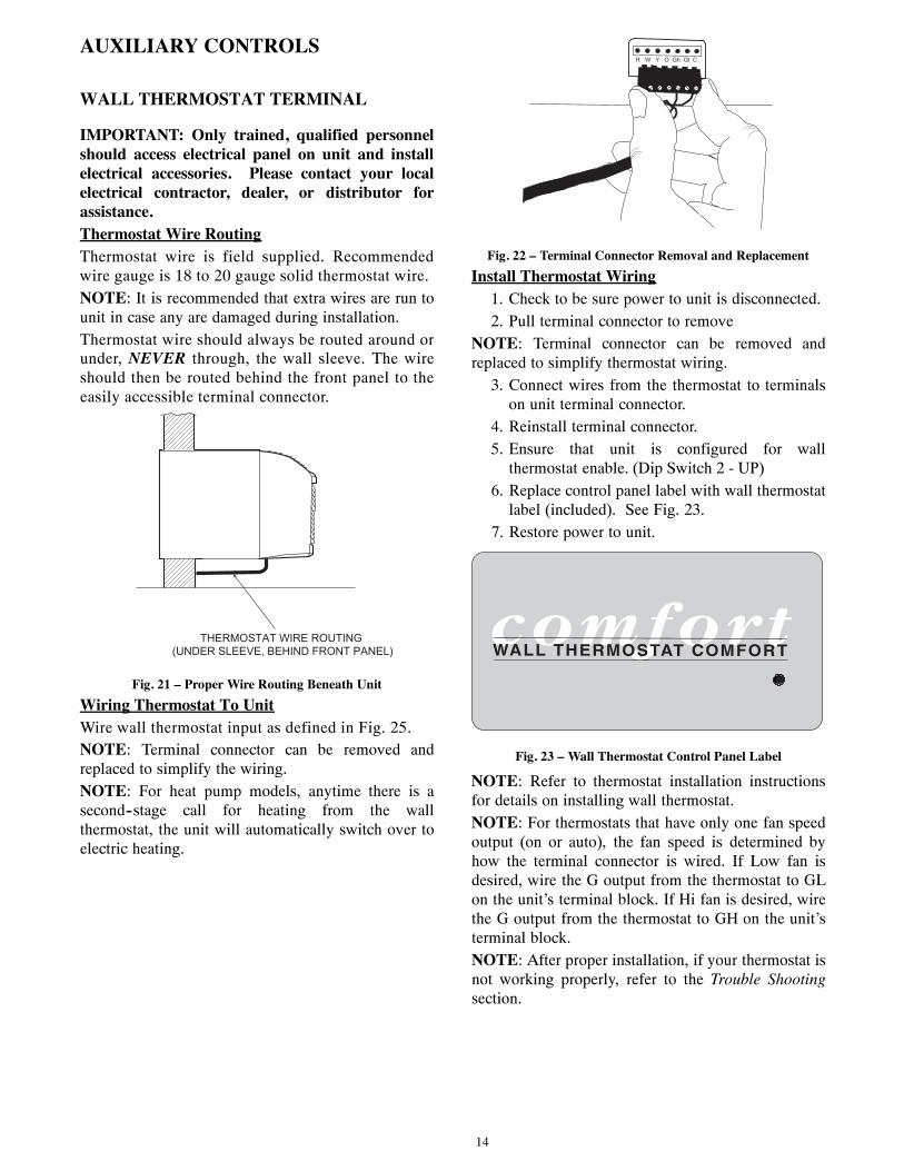
WALL THERMOSTAT TERMINAL
IMPORTANT: Only trained, qualified personnelshould access electrical panel on unit and installelectrical accessories. Please contact your localelectrical contractor, dealer, or distributor forassistance.Thermostat Wire RoutingThermostat wire is field supplied. Recommendedwire gauge is 18 to 20 gauge solid thermostat wire.NOTE: It is recommended that extra wires are run tounit in case any are damaged during installation.Thermostat wire should always be routed around orunder, NEVER through, the wall sleeve. The wireshould then be routed behind the front panel to theeasily accessible terminal connector.
THERMOSTAT WIRE ROUTING (UNDER SLEEVE, BEHIND FRONT PANEL)
Fig. 21 – Proper Wire Routing Beneath UnitWiring Thermostat To UnitWire wall thermostat input as defined in Fig. 25.NOTE: Terminal connector can be removed andreplaced to simplify the wiring.NOTE: For heat pump models, anytime there is asecond--stage call for heating from the wallthermostat, the unit will automatically switch over toelectric heating.
R W Y O Gh Gl C
Fig. 22 – Terminal Connector Removal and ReplacementInstall Thermostat Wiring
1. Check to be sure power to unit is disconnected.2. Pull terminal connector to remove
NOTE: Terminal connector can be removed andreplaced to simplify thermostat wiring.
3. Connect wires from the thermostat to terminalson unit terminal connector.
4. Reinstall terminal connector.5. Ensure that unit is configured for wall
thermostat enable. (Dip Switch 2 - UP)6. Replace control panel label with wall thermostat
label (included). See Fig. 23.7. Restore power to unit.
WALL THERMOSTAT COMFORT
Fig. 23 – Wall Thermostat Control Panel Label
NOTE: Refer to thermostat installation instructionsfor details on installing wall thermostat.NOTE: For thermostats that have only one fan speedoutput (on or auto), the fan speed is determined byhow the terminal connector is wired. If Low fan isdesired, wire the G output from the thermostat to GLon the unit’s terminal block. If Hi fan is desired, wirethe G output from the thermostat to GH on the unit’sterminal block.NOTE: After proper installation, if your thermostat isnot working properly, refer to the Trouble Shootingsection.
15
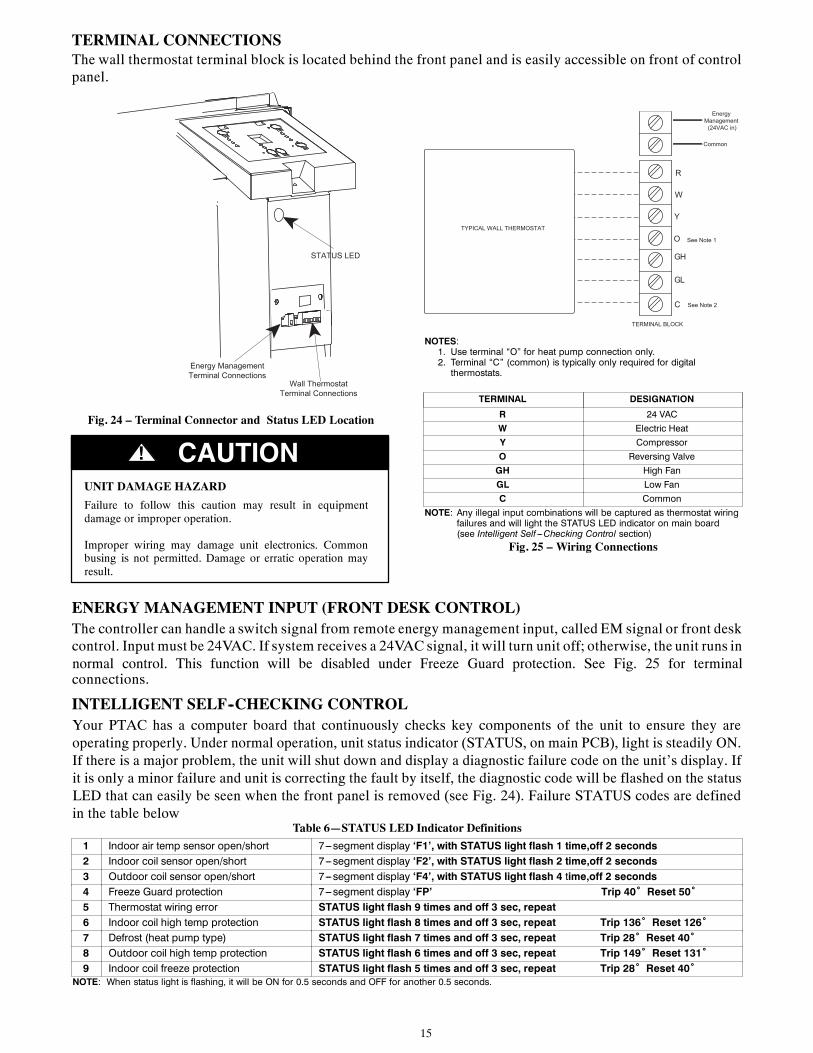
TERMINAL CONNECTIONSThe wall thermostat terminal block is located behind the front panel and is easily accessible on front of controlpanel.
STATUS LED
Wall Thermostat Terminal Connections
Energy Management Terminal Connections
Fig. 24 – Terminal Connector and Status LED Location
UNIT DAMAGE HAZARDFailure to follow this caution may result in equipmentdamage or improper operation.
Improper wiring may damage unit electronics. Commonbusing is not permitted. Damage or erratic operation mayresult.
CAUTION!
R
Y
GH
GL
C
W
O
Common
Energy Management
(24VAC in)
TYPICAL WALL THERMOSTAT
TERMINAL BLOCK
See Note 1
See Note 2
NOTES:1. Use terminal “O” for heat pump connection only.2. Terminal “C” (common) is typically only required for digital
thermostats.
TERMINAL DESIGNATION
R 24 VAC
W Electric Heat
Y Compressor
O Reversing Valve
GH High Fan
GL Low Fan
C Common
NOTE: Any illegal input combinations will be captured as thermostat wiringfailures and will light the STATUS LED indicator on main board(see Intelligent Self ---Checking Control section)
Fig. 25 – Wiring Connections
ENERGY MANAGEMENT INPUT (FRONT DESK CONTROL)The controller can handle a switch signal from remote energy management input, called EM signal or front deskcontrol. Input must be 24VAC. If system receives a 24VAC signal, it will turn unit off; otherwise, the unit runs in
connections.
INTELLIGENT SELF--CHECKING CONTROL
Table 6—STATUS LED Indicator Definitions1 Indoor air temp sensor open/short 7---segment display ‘F1’, with STATUS light flash 1 time,off 2 seconds2 Indoor coil sensor open/short 7---segment display ‘F2’, with STATUS light flash 2 time,off 2 seconds3 Outdoor coil sensor open/short 7---segment display ‘F4’, with STATUS light flash 4 time,off 2 seconds4 Freeze Guard protection 7---segment display ‘FP’ Trip 40˚ Reset 50˚5 Thermostat wiring error STATUS light flash 9 times and off 3 sec, repeat 6 Indoor coil high temp protection STATUS light flash 8 times and off 3 sec, repeat Trip 136˚ Reset 126˚7 Defrost (heat pump type) STATUS light flash 7 times and off 3 sec, repeat Trip 28˚ Reset 40˚8 Outdoor coil high temp protection STATUS light flash 6 times and off 3 sec, repeat Trip 149˚ Reset 131˚9 Indoor coil freeze protection STATUS light flash 5 times and off 3 sec, repeat Trip 28˚ Reset 40˚
NOTE: When status light is flashing, it will be ON for 0.5 seconds and OFF for another 0.5 seconds.
Your PTAC has a computer board that continuously checks key components of the unit to ensure they are operating properly. Under normal operation, unit status indicator (STATUS, on main PCB), light is steadily ON. If there is a major problem, the unit will shut down and display a diagnostic failure code on the unit’s display. If it is only a minor failure and unit is correcting the fault by itself, the diagnostic code will be flashed on the status LED that can easily be seen when the front panel is removed (see Fig. 24). Failure STATUS codes are defined in the table below
normal control. This function will be disabled under Freeze Guard protection. See Fig. 25 for terminal
16
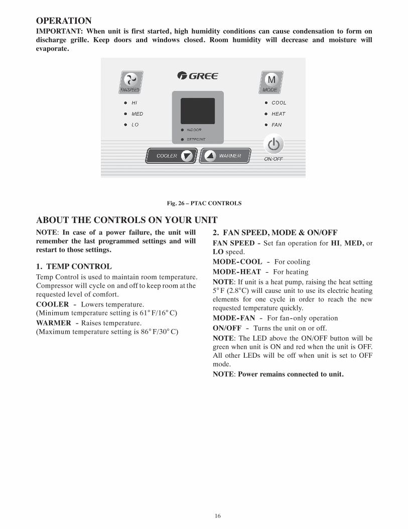
OPERATIONIMPORTANT: When unit is first started, high humidity conditions can cause condensation to form ondischarge grille. Keep doors and windows closed. Room humidity will decrease and moisture willevaporate.
Fig. 26 – PTAC CONTROLS
ABOUT THE CONTROLS ON YOUR UNITNOTE: In case of a power failure, the unit willremember the last programmed settings and willrestart to those settings.
1. TEMP CONTROLTemp Control is used to maintain room temperature.Compressor will cycle on and off to keep room at therequested level of comfort.COOLER -- Lowers temperature.(Minimum temperature setting is 61°F/16°C)WARMER -- Raises temperature.(Maximum temperature setting is 86°F/30°C)
2. FAN SPEED, MODE & ON/OFFFAN SPEED -- Set fan operation for HI, MED, orLO speed.MODE--COOL -- For coolingMODE--HEAT -- For heatingNOTE: If unit is a heat pump, raising the heat setting5°F (2.8°C) will cause unit to use its electric heatingelements for one cycle in order to reach the newrequested temperature quickly.MODE--FAN -- For fan--only operationON/OFF -- Turns the unit on or off.NOTE: The LED above the ON/OFF button will begreen when unit is ON and red when the unit is OFF.All other LEDs will be off when unit is set to OFFmode.NOTE: Power remains connected to unit.
17
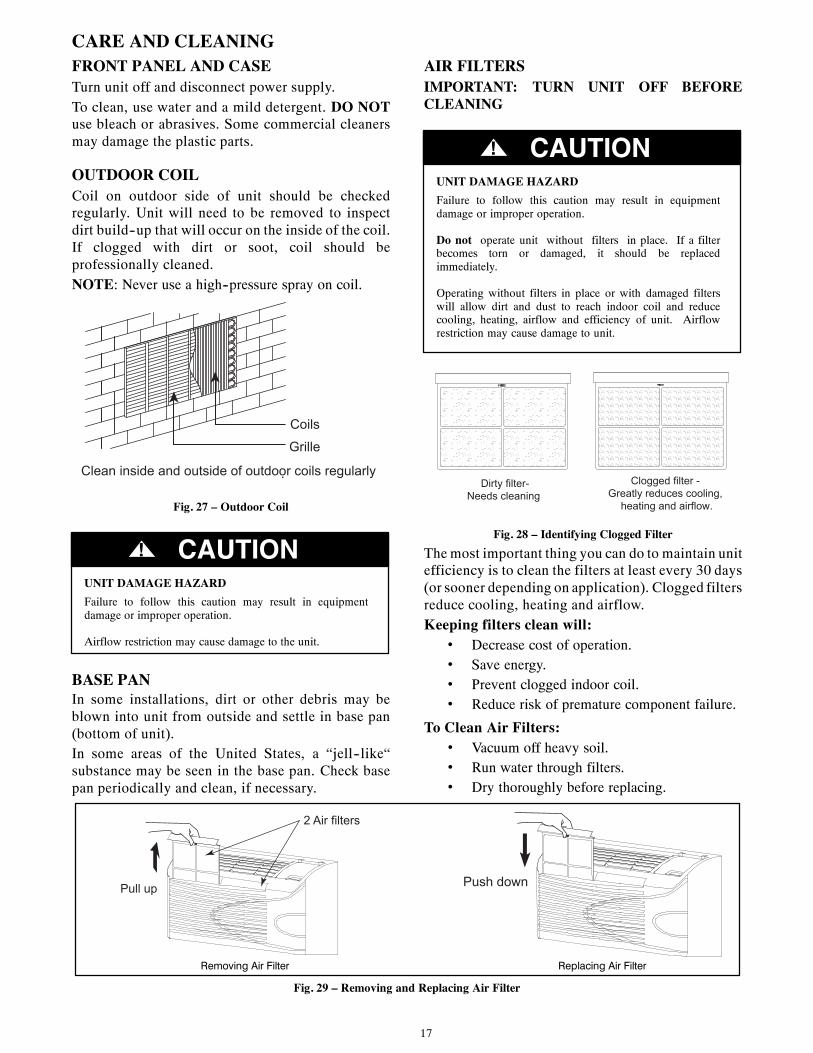
CARE AND CLEANINGFRONT PANEL AND CASETurn unit off and disconnect power supply.To clean, use water and a mild detergent. DO NOTuse bleach or abrasives. Some commercial cleanersmay damage the plastic parts.
OUTDOOR COILCoil on outdoor side of unit should be checkedregularly. Unit will need to be removed to inspectdirt build--up that will occur on the inside of the coil.If clogged with dirt or soot, coil should beprofessionally cleaned.NOTE: Never use a high--pressure spray on coil.
Coils
Grille
Clean inside and outside of outdoor coils regularly .
Fig. 27 – Outdoor Coil
UNIT DAMAGE HAZARDFailure to follow this caution may result in equipmentdamage or improper operation.
Airflow restriction may cause damage to the unit.
CAUTION!
BASE PANIn some installations, dirt or other debris may beblown into unit from outside and settle in base pan(bottom of unit).In some areas of the United States, a “jell--like“substance may be seen in the base pan. Check basepan periodically and clean, if necessary.
AIR FILTERSIMPORTANT: TURN UNIT OFF BEFORECLEANING
UNIT DAMAGE HAZARDFailure to follow this caution may result in equipmentdamage or improper operation.
Do not operate unit without filters in place. If a filterbecomes torn or damaged, it should be replacedimmediately.
Operating without filters in place or with damaged filterswill allow dirt and dust to reach indoor coil and reducecooling, heating, airflow and efficiency of unit. Airflowrestriction may cause damage to unit.
CAUTION!
Dirty filter- Needs cleaning
Clogged filter - Greatly reduces cooling,
heating and airflow.
Fig. 28 – Identifying Clogged FilterThe most important thing you can do to maintain unitefficiency is to clean the filters at least every 30 days(or sooner depending on application). Clogged filtersreduce cooling, heating and airflow.Keeping filters clean will:
• Decrease cost of operation.• Save energy.• Prevent clogged indoor coil.• Reduce risk of premature component failure.
To Clean Air Filters:• Vacuum off heavy soil.• Run water through filters.• Dry thoroughly before replacing.
2 Air filters
Pull up Push down
retliFriAgnicalpeRretliFriAgnivomeR
Fig. 29 – Removing and Replacing Air Filter
18
PREVENTATIVE MAINTENANCEPreventative maintenance is essential to proper unit operation, efficiency and longevity.To ensure equipment operates properly, it must be properly maintained. Equipment operation should be checkedand verified several times during each year. During regular unit inspection and maintenance, follow theguidelines below:
• Clean both sides of outdoor coil with warm water and a mild detergent. Do not use corrosive coil cleaners.(Never use high pressure spray on coils.)
• Clean basepan and outdoor vent filter.• Clean outdoor orifice and fan.• Clean indoor coil. (Never use high pressure spray on coils.)• Clean indoor fan, wire screen and front panel.• Clean or install new indoor--air inlet filter(s).• Clean wall sleeve and outdoor grille.• Inspect cord and receptacle.• Secure electrical connections.• Ensure front panel is properly mounted and not damaged.• Ensure wall sleeve is installed properly.• Ensure heat and cool cycles operate properly.
19
TROUBLESHOOTINGPOSSIBLE CAUSES SOLUTIONS
UNIT DOES NOT START
• Unit may have become unplugged• Fuse may have blown• Circuit breaker may have been tripped•Unit may be off or in wall thermostat mode.
Check section on dipswitch settings to verifydipswitches are set properly.
• Unit may be in a protection or diagnostic failuremode. See section on Intelligent Self ---checkingControl.
• Check that plug is plugged securely in wall receptacle.Note :Plug has a test/reset button on it. Make sure that the plughas not tripped.
• Replace the fuse. See Note 1.• Reset circuit breaker. See Note 1.• Turn unit on (bottom right button on keypad).
Note: If the unit turns on, the LED will be green. If the unit is off,the LED will be red. If there is no LED on, there is a problemwith power or damage to the control.
UNIT NOT COOLING/HEATING ROOM
•Unit air discharge section is blocked•Temperature setting is not high or low enough
Note: Setpoint limits may not allow the unit to heator cool the room to the temperature desired.Check section on dipswitch settings.
•Unit air filters are dirty.•Room is excessively hot or cold when unit is started.•Vent door left open•Unit may be in a protection or diagnostic failure
mode. Check section on Intelligent Self ---checkingControl.
•Compressor is in time delay. There is a protectivetime delay (approx. 3 minutes) on starting thecompressor after a power outage (or restartingafter it has been turned off), to prevent tripping ofthe compressor overload.
•Make sure that curtains, blinds or furniture are not restricting orblocking unit airflow.
•Reset to a lower or higher temperature setting.•Remove and clean filters.•Allow sufficient amount of time for unit to heat or cool the room.
Start heating or cooling early before outdoor temperature, cookingheat or gatherings of people make room uncomfortable.
•Close vent door.•Check dipswitch settings for desired comfort.
Wait approximately 3 minutes for compressor to start
DISPLAY HAS STRANGENUMBERS/CHARACTERS ON IT
• The unit may be in a diagnostic condition. Check Intelligent Self ---checking Control section to determine if unit has had a failure.
• The unit may be set for °C (instead of °F), see the keypadconfiguration section
UNIT MAKING NOISES • Clicking, gurgling and whooshing noises are normal duringoperation of unit.
WATER DRIPPING OUTSIDE • If a drain kit has not been installed, condensation runoff duringvery hot and humid weather is normal. See Note 2. If a drain kit hasbeen installed and is connected to a drain system, check gasketsand fittings around drain for leaks and plugs.
WATER DRIPPING INSIDE
• Wall sleeve is not installed level • Wall sleeve must be installed level for proper drainage ofcondensation. Check that installation is level and make anynecessary adjustments.
ICE OR FROST FORMS ON INDOOR COIL
• Low outdoor temperature• Dirty filters
• When outdoor temperature is approximately 55°F (12.8°C) orbelow, frost may form on the indoor coil when unit is in Coolingmode. Switch unit to FAN operation until ice or frost melts.
• Remove and clean filters.
COMPRESSOR PROTECTION• Power may have cycled, so compressor is in a
restart protection.
• Random Compressor restart --- Whenever the unit is plugged in,or power has been restarted, a random compressor restart willoccur. After a power outage, the compressor will restart afterapproximately 3 minutes.
• Compressor Protection --- To prevent short cycling of thecompressor, there is a random startup delay of 3 minutes and aminimum compressor run time of 3 minutes.
NOTES:1. If circuit breaker is tripped or fuse is blown more than once, contact a qualified electrician.2. If unit is installed where condensation drainage could drip in an undesirable location, an accessory drain kit should be installed and connected to drain
system.
20
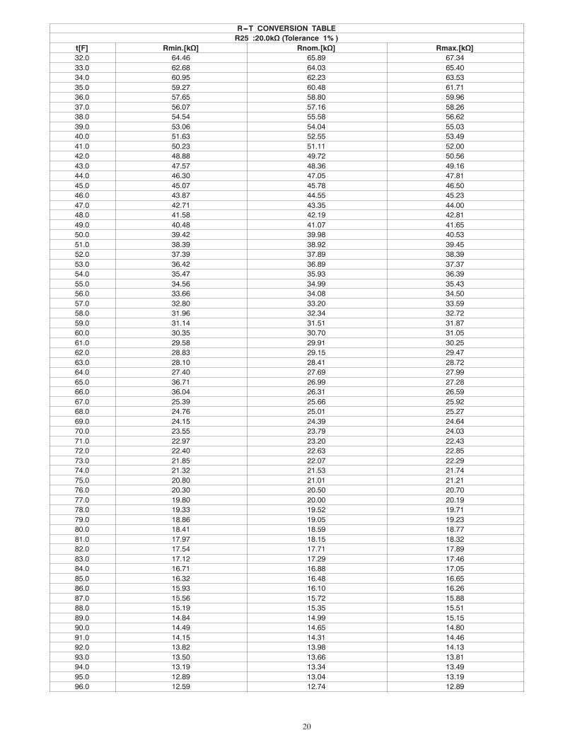
R---T CONVERSION TABLER25 :20.0kΩ (Tolerance 1% )
t[F] Rmin.[kΩ] Rnom.[kΩ] Rmax.[kΩ]32.0 64.46 65.89 67.3433.0 62.68 64.03 65.4034.0 60.95 62.23 63.5335.0 59.27 60.48 61.7136.0 57.65 58.80 59.9637.0 56.07 57.16 58.2638.0 54.54 55.58 56.6239.0 53.06 54.04 55.0340.0 51.63 52.55 53.4941.0 50.23 51.11 52.0042.0 48.88 49.72 50.5643.0 47.57 48.36 49.1644.0 46.30 47.05 47.8145.0 45.07 45.78 46.5046.0 43.87 44.55 45.2347.0 42.71 43.35 44.0048.0 41.58 42.19 42.8149.0 40.48 41.07 41.6550.0 39.42 39.98 40.5351.0 38.39 38.92 39.4552.0 37.39 37.89 38.3953.0 36.42 36.89 37.3754.0 35.47 35.93 36.3955.0 34.56 34.99 35.4356.0 33.66 34.08 34.5057.0 32.80 33.20 33.5958.0 31.96 32.34 32.7259.0 31.14 31.51 31.8760.0 30.35 30.70 31.0561.0 29.58 29.91 30.2562.0 28.83 29.15 29.4763.0 28.10 28.41 28.7264.0 27.40 27.69 27.9965.0 36.71 26.99 27.2866.0 36.04 26.31 26.5967.0 25.39 25.66 25.9268.0 24.76 25.01 25.2769.0 24.15 24.39 24.6470.0 23.55 23.79 24.0371.0 22.97 23.20 22.4372.0 22.40 22.63 22.8573.0 21.85 22.07 22.2974.0 21.32 21.53 21.7475.0 20.80 21.01 21.2176.0 20.30 20.50 20.7077.0 19.80 20.00 20.1978.0 19.33 19.52 19.7179.0 18.86 19.05 19.2380.0 18.41 18.59 18.7781.0 17.97 18.15 18.3282.0 17.54 17.71 17.8983.0 17.12 17.29 17.4684.0 16.71 16.88 17.0585.0 16.32 16.48 16.6586.0 15.93 16.10 16.2687.0 15.56 15.72 15.8888.0 15.19 15.35 15.5189.0 14.84 14.99 15.1590.0 14.49 14.65 14.8091.0 14.15 14.31 14.4692.0 13.82 13.98 14.1393.0 13.50 13.66 13.8194.0 13.19 13.34 13.4995.0 12.89 13.04 13.1996.0 12.59 12.74 12.89

21
R---T CONVERSION TABLE (cont.)R25 :20.0kΩ (Tolerance 1% )
t[F] Rmin.[kΩ] Rnom.[kΩ] Rmax.[kΩ]97.0 12.30 12.45 12.6098.0 12.02 12.17 12.3299.0 11.75 11.90 12.04100.0 11.48 11.63 11.77101.0 11.22 11.37 11.51102.0 10.97 11.11 11.26103.0 10.72 10.87 11.01104.0 10.48 10.62 10.77105.0 10.25 10.39 10.53106.0 10.02 10.16 10.30107.0 9.791 9.937 10.08108.0 9.573 9.719 9.866109.0 9.361 9.506 9.653110.0 9.154 9.299 9.446111.0 8.952 9.097 9.243112.0 8.755 8.900 9.046113.0 8.563 8.708 8.854114.0 8.376 8.520 8.667115.0 8.193 8.338 8.484116.0 8.015 8.159 8.305117.0 7.841 7.985 8.131118.0 7.671 7.815 7.961119.0 7.506 7.650 7.796120.0 7.344 7.488 7.634121.0 7.186 7.330 7.476122.0 7.033 7.176 7.322
22
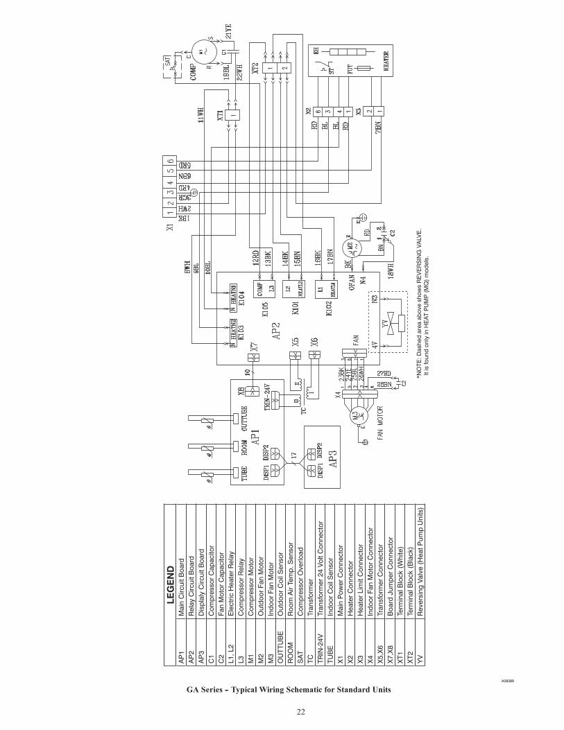
A08389
GA Series -- Typical Wiring Schematic for Standard Units
*NO
TE: D
ashe
d ar
ea a
bove
sho
ws
RE
VE
RS
ING
VA
LVE
. I
t is
foun
d on
ly in
HE
AT
PU
MP
(M
Q)
mod
els.
LEG
EN
DA
P1
Mai
n C
ircui
t Boa
rdA
P2
Rel
ay C
ircui
t Boa
rdA
P3
Dis
plal
y C
ircui
t Boa
rdC
1C
ompr
esso
r C
apac
itor
C2
Fan
Mot
or C
apac
itor
L1, L
2E
lect
ric H
eate
r R
elay
L3C
ompr
esso
r R
elay
M1
Com
pres
sor
Mot
orM
2O
utdo
or F
an M
otor
M3
Indo
or F
an M
otor
OU
TTU
BE
Out
door
Coi
l Sen
sor
RO
OM
Roo
m A
ir Te
mp.
Sen
sor
SA
TC
ompr
esso
r O
verlo
adTC
Tran
sfor
mer
TRIN
-24V
Tran
sfor
mer
24
Volt
Con
nect
orTU
BE
Indo
or C
oil S
enso
rX
1M
ain
Pow
er C
onne
ctor
X2
Hea
ter
Con
nect
orX
3H
eate
r Li
mit
Con
nect
orX
4In
door
Fan
Mot
or C
onne
ctor
X5,
X6
Tran
sfor
mer
Con
nect
orX
7,X
8B
oard
Jum
per
Con
nect
orX
T1Te
rmin
al B
lock
(W
hite
)X
T2Te
rmin
al B
lock
(B
lack
)Y
VR
ever
sing
Val
ve (
Hea
t Pum
p U
nits
)

23
Editi
on D
ate:
09-
10
Pac
kage
d Te
rmin
al
Air
Con
ditio
ner L
imite
d W
arra
nty
FIR
ST Y
EAR
PA
RTS
AN
D L
AB
OR
LIM
ITED
WA
RR
AN
TY –
Dur
ing
the
first
yea
r af
ter
purc
hase
, GR
EE
will
, thr
ough
its
auth
oriz
ed in
depe
nden
t ser
vici
ng d
eale
r or
ser
vice
st
atio
ns*,
and
free
of c
harg
e to
the
user
or
subs
eque
nt u
sers
, rep
air
or r
epla
ce a
ny p
arts
th
at fa
il du
e to
def
ect i
n m
ater
ial o
r w
orkm
ansh
ip. T
he r
epla
cem
ent p
art c
an b
e a
new
or
rem
anuf
actu
red
part
as p
rovi
ded
at G
RE
E’S
sol
e op
tion.
EX
TEN
DED
FO
UR
-YEA
R P
AR
TS A
ND
LA
BO
R L
IMIT
ED W
AR
RA
NTY
ON
SEA
LED
R
EFR
IGER
ATI
ON
SYS
TEM
ON
LY –
Dur
ing
the
seco
nd t
hrou
gh f
ifth
year
s af
ter
date
of
orig
inal
pur
chas
e, G
RE
E w
ill,
thro
ugh
its a
utho
rized
ser
vici
ng d
eale
rs a
nd s
ervi
ce
stat
ions
* an
d fre
e of
cha
rge
to t
he e
nd u
ser
or s
ubse
quen
t us
ers,
rep
air
or r
epla
ce t
he
com
pres
sor,
cond
ense
r, ev
apor
ator
or c
onne
ctin
g tu
bing
if it
faile
d du
e to
def
ect i
n m
ater
ial
or w
orkm
ansh
ip.
This
incl
udes
sys
tem
ref
riger
atio
n ch
arge
. Th
e re
plac
emen
t pa
rt ca
n be
ne
w o
r a re
man
ufac
ture
d pa
rt at
GR
EE
’S s
ole
optio
n.
LIM
ITA
TIO
N O
F W
AR
RA
NTI
ES –
ALL
IM
PLI
ED
WA
RR
AN
TIE
S (
INC
LUD
ING
IM
PLI
ED
W
AR
RA
NTI
ES
OF
ME
RC
HA
NTA
BIL
ITY
AN
D F
ITN
ES
S F
OR
PA
RTI
CU
LAR
US
E O
R
PU
RP
OS
E) A
RE
HE
RE
BY
LIM
ITE
D IN
DU
RA
TIO
N T
O T
HE
PE
RIO
D F
OR
WH
ICH
EA
CH
LI
MIT
ED
WA
RR
AN
TY I
S G
IVE
N A
ND
AP
PLI
ES
. S
OM
E S
TATE
S D
O N
OT
ALL
OW
LI
MIT
ATI
ON
S O
N H
OW
LO
NG
AN
IM
PLI
ED
WA
RR
AN
TY L
AS
TS,
SO
TH
E A
BO
VE
LI
MIT
ATI
ON
MA
Y N
OT
AP
PLY
TO
YO
U.
THE
EX
PR
ES
SE
D W
AR
RA
NTI
ES
MA
DE
IN
TH
IS W
AR
RA
NTY
AR
E E
XC
LUS
IVE
AN
D M
AY
NO
T B
E A
LTE
RE
D,
EN
LAR
GE
D,
OR
C
HA
NG
ED
BY
AN
Y D
ISTR
IBU
TOR
, DE
ALE
R, O
R O
THE
R P
ER
SO
N W
HA
TSO
EV
ER
. A
LL W
OR
K U
ND
ER
TH
E T
ER
MS
OF
THIS
WA
RR
AN
TY S
HA
LL B
E P
ER
FOR
ME
D
DU
RIN
G N
OR
MA
L W
OR
KIN
G H
OU
RS
. A
LL R
EP
LAC
EM
EN
T P
AR
TS,
WH
ETH
ER
NE
W
OR
R
EM
AN
UFA
CTU
RE
D,
AS
SU
ME
A
S
THE
IR
WA
RR
AN
TY
PE
RIO
D
ON
LY
THE
R
EM
AIN
ING
TIM
E P
ER
IOD
OF
THIS
WA
RR
AN
TY.
GR
EE W
ILL
NO
T B
E R
ESPO
NSI
BLE
FO
R:
1.
CLE
AN
ING
REQ
UIR
ED P
RIO
R T
O W
AR
RA
NTY
REP
AIR
. 2.
S
tand
ard
mai
nten
ance
, cl
eani
ng o
r da
mag
e re
sulti
ng f
rom
fai
lure
to
perfo
rm
norm
al m
aint
enan
ce a
s ou
tline
d in
the
owne
r’s m
anua
l. 3.
In
stru
ctio
n on
met
hods
of
cont
rol
and
use
of a
ir co
nditi
onin
g un
it af
ter
initi
al
inst
alla
tion.
4.
D
amag
e or
rep
airs
nee
ded
as c
onse
quen
ce o
f fa
ulty
inst
alla
tion
or a
pplic
atio
n.
This
is th
e re
spon
sibi
lity
of th
e in
stal
ler.
5.
Failu
re t
o st
art
due
to v
olta
ge c
ondi
tions
, bl
own
fuse
s, o
pen
circ
uit
brea
kers
or
any
othe
r dam
ages
due
to th
e in
adeq
uacy
or i
nter
rupt
ion
of e
lect
rical
ser
vice
s.
6.
Dam
age
or r
epai
rs n
eede
d as
con
sequ
ence
of
any
mis
appl
icat
ion,
abu
se,
unau
thor
ized
alte
ratio
n, im
prop
er s
ervi
cing
or o
pera
tion.
7.
D
amag
e as
a
resu
lt of
flo
ods,
w
inds
, fir
es,
light
ning
, ac
cide
nts,
co
rros
ive
envi
ronm
ent,
or o
ther
con
ditio
ns b
eyon
d th
e co
ntro
l of G
RE
E.
EX
CE
PTI
ON
TO
C
OR
RO
SIV
E
EN
VIR
ON
ME
NT
EX
CLU
SIO
N
IN
AB
OV
E
PA
RA
GR
AP
H –
Pac
ked
term
inal
uni
ts (
GA
Ser
ies)
bui
lt w
ith c
orro
sion
pro
tect
ion
are
exem
pt f
rom
the
exc
lusi
on –
“C
orro
sive
Env
ironm
ent.”
The
uni
t m
odel
nu
mbe
r is
iden
tifie
d on
the
nam
epla
te w
ith C
P s
uffix
. 8.
R
eim
burs
emen
t fo
r re
plac
emen
t pa
rts o
r re
pair
serv
ices
whi
ch a
re n
ot s
uppl
ied
or d
esig
nate
d by
GR
EE
and
whi
ch a
re s
peci
fical
ly c
over
ed u
nder
this
war
rant
y w
arra
nty.
9.
G
RE
E p
rodu
cts
inst
alle
d ou
tsid
e th
e co
ntin
enta
l U.S
.A.,
Ala
ska,
Haw
aii,
and
Can
ada.
10
. S
hipp
ing
dam
age
or d
amag
e as
a r
esul
t of
tra
nspo
rting
the
uni
t. Th
is i
s th
e re
spon
sibi
lity
of th
e se
lling
dea
ler o
r the
aut
horiz
ed s
ervi
ce
stat
ion.
11
. A
NY
SP
EC
IAL,
IN
DIR
EC
T O
R
CO
NS
EQ
UE
NTI
AL
PR
OP
ER
TY
OR
C
OM
ME
RC
IAL
DA
MA
GE
OF
AN
Y N
ATU
RE
WH
ATS
OE
VE
R.
Som
e st
ates
do
not
allo
w t
he e
xclu
sion
or
limita
tion
of in
cide
ntal
or
cons
eque
ntia
l dam
ages
, so
th
e ab
ove
limita
tion
or e
xclu
sion
may
not
app
ly to
you
. 12
. W
arra
nty
cove
rage
of a
cces
sory
item
s (w
all t
herm
osta
ts, w
all s
leev
es, e
tc.)
*Aut
horiz
ed in
depe
nden
t dea
lers
or s
ervi
ce s
tatio
ns a
re re
gist
ered
with
Gre
e th
roug
h its
dis
tribu
tor o
rgan
izat
ion.
This
war
rant
y gi
ves
you
spec
ific
lega
l rig
hts,
and
you
may
als
o ha
ve o
ther
righ
ts w
hich
var
y fr
om s
tate
to s
tate
.
EXTE
ND
ED
FOU
R-Y
EAR
PA
RTS
O
NLY
LI
MIT
ED
WA
RA
NTY
O
N
NO
N-S
EALE
D
REF
RIG
ERA
TIO
N S
YSTE
M O
NLY
– D
urin
g th
e se
cond
thr
ough
fift
h ye
ars
afte
r da
te o
f or
igin
al p
urch
ase,
Gre
e w
ill,
thro
ugh
its a
utho
rized
ser
vici
ng d
eale
rs a
nd s
ervi
ce s
tatio
ns
and
free
of c
harg
e to
the
end
user
or
subs
eque
nt u
sers
, rep
air
or r
epla
ce a
ny n
on-s
eale
d sy
stem
par
t (m
otor
, sol
enoi
d, th
erm
isto
r, re
lays
, sw
itch,
cap
acito
r, ov
erlo
ad, d
rain
val
ve, f
an,
stat
or) i
f fai
led
due
to d
efec
t in
mat
eria
l or w
orkm
ansh
ip. T
he re
plac
emen
t par
t can
be
new
or
a r
eman
ufac
ture
d pa
rt at
GR
EE
’S s
ole
optio
n. T
HIS
LIM
ITE
D W
AR
RA
NTY
DO
ES
NO
T IN
CLU
DE
LA
BO
R,
user
is
resp
onsi
ble
for
labo
r, in
clud
ing
cost
of
diag
nosi
s of
pro
blem
, re
mov
al a
nd t
rans
porta
tion
of t
he a
ir co
nditi
oner
to
and
from
the
ser
vice
cen
ter,
and
rein
stal
latio
n ch
arge
s ne
cess
ary
to a
ccom
plis
h re
pair.
13.
Inst
alla
tions
of n
on-c
orro
sion
pro
tect
ed m
odel
s w
ithin
one
(1) m
ile o
f a c
orro
sive
bo
dy o
f wat
er o
r en
viro
nmen
t sha
ll vo
id th
e
EX
TEN
DE
D F
OU
R-Y
EA
R P
AR
TS
AN
D L
AB
OR
LIM
ITE
D W
AR
RA
NTY
ON
SE
ALE
D R
EFR
IGE
RA
TIO
N S
YS
TEM
O
NLY
and
EX
TEN
DE
D F
OU
R-Y
EA
R P
AR
TS O
NLY
LIM
ITE
D W
AR
AN
TY O
N
NO
N-S
EA
LED
RE
FRIG
ER
ATI
ON
SY
STE
M O
NLY
lim
ited
war
rant
ies
.
24
Cat
alog
Num
ber:
490
04D
P58
Editi
on D
ate:
09/
10
IF Y
OU
R A
IR C
ON
DIT
ION
ER D
OES
NO
T W
OR
K, F
OLL
OW
TH
ESE
STEP
S IN
OR
DER
:
1.
CH
ECK
TH
E TH
ING
S YO
U C
AN
DO
YO
UR
SELF
. The
se in
clud
e be
ing
sure
the
air c
ondi
tione
r is
plug
ged
in fi
rmly
in a
n ap
prop
riate
rece
ptac
le, c
heck
ing
the
fuse
or
circ
uit b
reak
er a
nd e
nsur
ing
its re
plac
emen
t or r
eset
ting,
if n
eces
sary
, and
re
read
ing
the
inst
ruct
ion
book
to e
nsur
e th
at a
ll co
ntro
ls a
re s
et p
rope
rly. B
y do
ing
this
you
can
sav
e m
oney
. Man
y un
nece
ssar
y se
rvic
e ca
lls re
sult
in th
e se
rvic
eman
doi
ng w
hat t
he o
wne
r can
do
for h
im o
r her
self.
2.
CO
NTA
CT
YOU
R D
EALE
R O
R T
HE
AU
THO
RIZ
ED S
ERVI
CE
CEN
TER
HE
REC
OM
MEN
DS
. The
y ha
ve b
een
set u
p to
han
dle
the
grea
t maj
ority
of
all
poss
ible
ser
vice
pro
blem
s. T
he q
uick
est,
sure
st a
nd b
est w
ay to
get
yo
ur a
ir co
nditi
oner
bac
k in
ser
vice
is to
use
this
ste
p be
fore
pro
ceed
ing
furth
er.
3.
C
ON
TAC
T TH
E D
ISTR
IBU
TOR
SER
VIN
G Y
OU
R A
REA
. You
r dea
ler
ca
n gi
ve y
ou h
is n
ame
or y
ou c
an c
onsu
lt yo
ur y
ello
w p
ages
.
Copyright 2010 Gree Electric Appliance Inc.
Manufacturer reserves the right to change, at any time, specifications and designs without notice and without obligations.
Catalog No. PTAC-GA-2SIPrinted in U.S.A. Edition Date: 09/10
Top Related