


Languages
Pages
Legal


This document and the information contained herein, is the exclusive property of Konecranes Plc and represents a non-public, confidential and proprietary trade secret that may not be reproduced, disclosed to third parties, altered or otherwise employed in any manner whatsoever without the express written consent of Konecranes Plc. Copyright © (2007) Konecranes Plc. All rights reserved.
INSTALLATION AND MAINTENANCE MANUAL XN CHAIN HOIST XN16 - XN20 – XN25
English
STD-K-KHA-F-CQD-ENG

XN16-20-25 I&M MANUAL/EN/06.07.2007
2/65 This document and the information contained herein, is the exclusive property of Konecranes Plc and represents a non-public, confidential and proprietary trade secret that may not be reproduced, disclosed to third parties, altered or otherwise employed in any manner whatsoever without the express written consent of Konecranes Plc. Copyright © (2007) Konecranes Plc. All rights reserved.
THIS PAGE INTENTIONALLY LEFT BLANK

XN16-20-25 I&M MANUAL/EN/06.07.2007
3/65 This document and the information contained herein, is the exclusive property of Konecranes Plc and represents a non-public, confidential and proprietary trade secret that may not be reproduced, disclosed to third parties, altered or otherwise employed in any manner whatsoever without the express written consent of Konecranes Plc. Copyright © (2007) Konecranes Plc. All rights reserved.
m CAUTION: Read the instructions supplied with the product before installation and commissioning.
m CAUTION: Keep the instructions in a safe place for future reference.
Table of contents
1 INTRODUCTION ........................................................................................................................................ 5
1.1 Contact Information .............................................................................................................................. 5
1.2 Warranty ............................................................................................................................................... 5
1.3 Disclaimer ............................................................................................................................................. 5
1.4 Safety.................................................................................................................................................... 6
1.5 Placards and Instructions ..................................................................................................................... 8
2 INSTALLATION ......................................................................................................................................... 9
2.1 General ................................................................................................................................................. 9
2.2 Chain Container Installation ................................................................................................................. 9
2.3 Lubrication ............................................................................................................................................ 9
2.4 Mounting ............................................................................................................................................. 10
2.5 Load Hook Throat Opening ................................................................................................................ 10
2.6 Electrical Connection.......................................................................................................................... 11
2.7 Three Phase Power Connections....................................................................................................... 12
3 INITIAL START-UP.................................................................................................................................. 13
3.1 General ............................................................................................................................................... 13
3.2 Correcting the Direction of Hook Travel ............................................................................................. 13
3.3 Operational Checks – No Load .......................................................................................................... 14
3.4 Operational Checks – With Load........................................................................................................ 14
4 HOIST OPERATION ................................................................................................................................ 15
5 MAINTENANCE ....................................................................................................................................... 17
5.1 Basic Hoist Construction .................................................................................................................... 17
5.2 Hoist Motor and Brake Assembly ....................................................................................................... 18
5.2.1 Replacement Criteria for Motor Brakes ..................................................................................... 21
5.3 Torque Limiter (Refer to Figure 5.4) ................................................................................................... 23
5.4 Load Chain ......................................................................................................................................... 24
5.5 Maintenance Inspection...................................................................................................................... 24
5.6 Load Chain Specifications (see Figure 5.5) ....................................................................................... 26
5.7 Removing the Load Chain .................................................................................................................. 26
5.8 Installing the Load Chain .................................................................................................................... 27
5.9 Fall Stop Assembly (Refer to Figure 5.8) ........................................................................................... 29
5.10 Chain Container ............................................................................................................................. 30
5.11 Upper and Lower Travel Safety Limit Switch ................................................................................. 31
5.12 Upper and Lower Rotary Travel Limit Switch................................................................................. 32
5.13 Hooks ............................................................................................................................................. 33
5.14 Hook Inspection.............................................................................................................................. 34
5.15 Hook Dimensions ........................................................................................................................... 35
5.16 Top Hook........................................................................................................................................ 36
5.17 Controls .......................................................................................................................................... 37
5.18 Two Speed – Three Phase – 208 / 230 / 460 Volt – Power Circuit ............................................... 39
5.19 Two Speed – Three Phase – 208 / 230 / 460 Volt – Control Circuit .............................................. 40
5.20 Two Speed – Three Phase – 575 Volt – Power Circuit.................................................................. 41
5.21 Two Speed – Three Phase – 575 Volt – Control Circuit ................................................................ 42
5.22 Wiring Diagram – 3 Button – Push Button ..................................................................................... 43
5.23 Wiring Diagram – 5 Button – Push Button ..................................................................................... 44
5.24 Wiring Diagram – 7 Button – Push Button ..................................................................................... 45
6 PREVENTATIVE MAINTENANCE .......................................................................................................... 46
6.1 Maintenance and Inspection Table..................................................................................................... 46

XN16-20-25 I&M MANUAL/EN/06.07.2007
4/65 This document and the information contained herein, is the exclusive property of Konecranes Plc and represents a non-public, confidential and proprietary trade secret that may not be reproduced, disclosed to third parties, altered or otherwise employed in any manner whatsoever without the express written consent of Konecranes Plc. Copyright © (2007) Konecranes Plc. All rights reserved.
6.2 Lubrication .......................................................................................................................................... 47
6.3 Recommended Technical Support for Various Spare Parts .............................................................. 48
6.4 Screw Tightening Torque (lb-ft) Specifications................................................................................... 48
6.5 Troubleshooting .................................................................................................................................. 49
7 PARTS ILLUSTRATIONS........................................................................................................................ 50
7.1 Hoist Gearbox Components ............................................................................................................... 50
7.2 C16 / C20 / C25 Hoist Motor & Brake Assembly............................................................................ 52
7.3 Lifting Assembly – C16 Only .............................................................................................................. 54
7.4 Lifting Assembly – C20/25 Only ......................................................................................................... 56
7.5 C16 / C20 / C25 Electrical Control Assembly..................................................................................... 58
7.6 Double Brake (Option) C16 / C20 / C25............................................................................................. 60
7.7 Push Button Assembly – Horizontal Pairs of Buttons......................................................................... 61
7.8 Push Button Assembly – Horizontal Pairs of Buttons........................................................................ 62
7.9 Push Button Assembly – Vertical Pairs of Buttons (Option)............................................................... 63
7.10 Push Button Assembly – Vertical Buttons (Option)........................................................................ 65

XN16-20-25 I&M MANUAL/EN/06.07.2007
5/65 This document and the information contained herein, is the exclusive property of Konecranes Plc and represents a non-public, confidential and proprietary trade secret that may not be reproduced, disclosed to third parties, altered or otherwise employed in any manner whatsoever without the express written consent of Konecranes Plc. Copyright © (2007) Konecranes Plc. All rights reserved.
1 INTRODUCTION
1.1 Contact Information
Please do not hesitate to use for following contact information in the event that you may need assistance:
Konecranes
4505 Gateway Boulevard
Springfield, OH 45502
General Telephone: 937 - 525-1190
Toll Free Telephone (US): 866 - 291-1754
General Fax: 937 - 328-5165
1.2 Warranty
All sales are subject to the Konecranes Standard Terms and Conditions of Sale and Product Warranty. Copies are available upon request from Konecranes and are expressly incorporated by reference hereto.
1.3 Disclaimer
This Manual has been prepared by Konecranes to provide information and suggestions for hoist installation, maintenance, and inspection personnel. This manual should be used in conjunction with the XN Electric Chain Hoist Operator’s Manual to teach safe operating practices to all personnel associated with hoist operations and maintenance.
It is NOT intended that the recommendations in this manual take precedence over existing plant safety rules and regulations or OSHA regulations. However, a thorough study of the following information should provide a better understanding of proper installation, maintenance, and inspection procedures that are to be followed in order to afford a greater margin of safety for people and machinery in the area of hoist operations.
It must be recognized that this is a manual of recommendations for the Hoist Installation, Maintenance, and Inspection personnel and its use is permissive not mandatory. It is the responsibility of the hoist owner to make personnel aware of all federal, state, and local codes and regulations. The owner is responsible for providing instruction and insuring that certain installation, maintenance, and inspection personnel are properly trained.
XN16-20-25 I&M MANUAL/EN/06.07.2007
6/65 This document and the information contained herein, is the exclusive property of Konecranes Plc and represents a non-public, confidential and proprietary trade secret that may not be reproduced, disclosed to third parties, altered or otherwise employed in any manner whatsoever without the express written consent of Konecranes Plc. Copyright © (2007) Konecranes Plc. All rights reserved.
1.4 Safety
���� Read and understand this manual before using the hoist.
Important issues to remember during installation, operation, maintenance, and inspection are provided at the hoist control stations, at various locations on the hoist, in this manual, and in the XN Electric Chain Hoist Operator’s Manual. These issues are indicated by DANGER, WARNING, or CAUTION instructions or placards that alert personnel to potential hazards, proper operation, load limitations, and more.
m
DANGER: Indicates an imminently hazardous situation, which, if not avoided, will result in death or serious injury.
m
WARNING: Indicates a potentially hazardous situation, which, if not avoided, could result in death or serious injury.
m
CAUTION: Indicates a potentially hazardous situation, which, if not avoided, may result in minor or moderate injury. It may also be used to alert against unsafe practices.
Taking precedence over any specific rule, however, is the most important rule of all:
“USE COMMON SENSE”
It is a responsibility of the hoist owner / user to establish programs to:
1. Train and designate hoist operators, and 2. Train and designate hoist inspectors / maintenance personnel.
XN16-20-25 I&M MANUAL/EN/06.07.2007
7/65 This document and the information contained herein, is the exclusive property of Konecranes Plc and represents a non-public, confidential and proprietary trade secret that may not be reproduced, disclosed to third parties, altered or otherwise employed in any manner whatsoever without the express written consent of Konecranes Plc. Copyright © (2007) Konecranes Plc. All rights reserved.
The words SHALL and SHOULD are used throughout this manual in accordance with definitions in the ASME B30 standards as follows:
SHALL indicates a rule is mandatory and must be followed.
SHOULD indicates a rule is a recommendation, the advisability of which depends on the facts in each situation.
Hoist operation, hoist inspection, and hoist maintenance personnel training programs should be based on requirements in accordance with the latest edition of:
� ASME B30.16 Safety Standard for Overhead Hoists ( Underhung )
Such training should also provide information for compliance with any Federal, State, or Local Code requirements, and existing plant safety rules and regulations.
If an overhead hoist is installed as part of an overhead crane or monorail system, training programs should also include requirements in accordance with the latest editions, as applicable, of:
� ASME B30.2 Safety Standard for Overhead and Gantry Cranes, Top Running Bridge, Single or Multiple Girder, Top Running Trolley Hoist
� ASME B30.11 Safety Standard for Monorails and Underhung Cranes � ASME B30.17 Safety Standard for Overhead and Gantry Cranes, Top Running Bridge, Single
Girder, Underhung Hoist.

XN16-20-25 I&M MANUAL/EN/06.07.2007
8/65 This document and the information contained herein, is the exclusive property of Konecranes Plc and represents a non-public, confidential and proprietary trade secret that may not be reproduced, disclosed to third parties, altered or otherwise employed in any manner whatsoever without the express written consent of Konecranes Plc. Copyright © (2007) Konecranes Plc. All rights reserved.
NOTICE:
���� It is a responsibility of the owner / user to install, inspect, test, maintain, and operate a hoist in accordance with the ASME B30.16 Safety Standard, OSHA Regulations, and ANSI / NFPA 70, National Electric Code. If the hoist is installed as part of a total lifting system, it is also the responsibility of the owner / user to comply with the applicable ASME B30 volume that addresses other types of equipment used in the system.
���� Further, it is the responsibility of the owner / user to require that all personnel who will install, inspect, test, maintain, and operate a hoist read the contents of this manual, XN Electric Chain Hoist Operator’s Manual, ASME B30.16 Safety Standards for Overhead Hoists (Underhung), OSHA Regulations, and ANSI / NFPA 70, National Electric Code. If the hoist is installed as part of a total lifting system, all personnel must also read the applicable ASME B30 volume that addresses other types of equipment used in the system.
m DANGER: Failure to read and comply with any one of the limitations noted in this manual can result in product failure, serious bodily injury or death, and / or property damage.
Konecranes has no direct involvement or control over the hoist’s operation and application. Conforming to good safety practices is the responsibility of the owner, the user, and its operating personnel.
Only those Authorized and Qualified Personnel who have shown that they have read and have understood this manual and the XN Electric Chain Hoist Operator’s Manual should be permitted to operate the hoist.
The owner / user SHALL insure that all Operators read and understand the XN Electric Chain Hoist Operator’s Manual prior to operating the hoist.
1.5 Placards and Instructions
READ and OBEY all Danger, Warning, Caution, and Operating Instructions on the hoist and in this manual and XN Electric Chain Hoist Operator’s Manual. Make sure that all placards are in place and legible.
Failure to comply with safety precautions in this manual and on the hoist is a safety violation that may result in serious injury, death, or property damage.
XN16-20-25 I&M MANUAL/EN/06.07.2007
9/65 This document and the information contained herein, is the exclusive property of Konecranes Plc and represents a non-public, confidential and proprietary trade secret that may not be reproduced, disclosed to third parties, altered or otherwise employed in any manner whatsoever without the express written consent of Konecranes Plc. Copyright © (2007) Konecranes Plc. All rights reserved.
2 INSTALLATION
m DANGER: Before installing, removing, inspection, or performing any maintenance on a hoist, the main switch shall be de-energized. Lock and tag the main switch in the de-energized position in accordance with ANSI Z244.1. Follow other maintenance procedures outlined in this manual and ASME B30.16.
2.1 General
Prior to installation, the unit shall be checked thoroughly for damage during shipment or handling at the job site.
Each complete electric chain hoist is load tested at the factory at 125% of the nameplate-rated capacity.
All hoists are designed for the type of mounting specified by the purchaser. The adequacy of the supporting members (monorail beams, cranes, hangers, supports, framing, etc.) is the responsibility of user / owner and shall be determined or verified by qualified personnel.
Read the instructions contained in this manual and the XN Electric Chain Hoist Operator’s Manual as well as any other related manuals. Observe the warning tags attached to the unit before the installation is started.
2.2 Chain Container Installation
m CAUTION: REMOVE SMALL CHAIN CONNECTING CHAIN CONTAINER TO HOIST BODY. THIS
CHAIN IS TO BE USED ONLY DURING INSTALLATION AND THEN MUST BE REMOVED.
Due to the weight of the chain and chain container on all Models XN 16 / 20 / 25, the chain container is attached to hoist body with a LIGHT DUTY chain to facilitate removing hoist and chain container from packing container for assembly of chain container to hoist body.
2.3 Lubrication
The hoist gear case comes completely pre-lubricated with grease.
���� Note: Open trolley wheel gearing has not been greased at the factory. See the trolley manual for proper gear lubricant to use before installing hoist.
The load chain requires lubrication prior to first use. Chain lubricant is included with shipment of each new chain hoist.

XN16-20-25 I&M MANUAL/EN/06.07.2007
10/65 This document and the information contained herein, is the exclusive property of Konecranes Plc and represents a non-public, confidential and proprietary trade secret that may not be reproduced, disclosed to third parties, altered or otherwise employed in any manner whatsoever without the express written consent of Konecranes Plc. Copyright © (2007) Konecranes Plc. All rights reserved.
2.4 Mounting
Below are three types of mounting:
1. Hook Mounted 2. Base Mounted 3. Coupling Mounted 4. Trolley Mounted – NOT SHOWN – is accomplished via a Hook or Trolley Coupling to the Trolley
Assembly.
Figure 2.1. Mounting Types
For all trolley-mounted hoists, refer to appropriate trolley manual for trolley installation instructions.
After a trolley-mounted hoist has been assembled to a beam, check for balance. Each trolley-mounted hoist is balanced at the factory for “as shipped” condition. Any auxiliary devices (radio control, lights, hose reels, etc.) furnished and mounted by “others” may require additional counterweight. Hoists must hang straight without a load or there will be a noticeable “kick” when a load is applied to hook. An unbalanced hoist / trolley may result in damage to equipment.
2.5 Load Hook Throat Opening
m CAUTION: ANSI B30.16-1998 recommends that the throat opening of a load hook be measured and recorded prior to putting a hoist into service and that a gage be made to provide a quick visual inspection for a bent hook as required during routine inspections.
m CAUTION: Record this information before initial start-up. See Section 5.20 for more detailed hook information.

XN16-20-25 I&M MANUAL/EN/06.07.2007
11/65 This document and the information contained herein, is the exclusive property of Konecranes Plc and represents a non-public, confidential and proprietary trade secret that may not be reproduced, disclosed to third parties, altered or otherwise employed in any manner whatsoever without the express written consent of Konecranes Plc. Copyright © (2007) Konecranes Plc. All rights reserved.
2.6 Electrical Connection
The user / owner must provide the main power supply hardware (cable, conductor bar, fuses, disconnect switch, etc.).
m CAUTION: Make sure that the power supply voltage is the same as that shown on hoist serial plate / nameplate.
m CAUTION: Make sure that fuses and other current overload devices are in place to protect the power supply.
m CAUTION: Make sure that power cable or conductors have sufficient capacity to maintain the hoist supply voltage by ±5 percent of nominal voltage under all operating conditions. Poor voltage regulation may cause motor overheating or sluggishness, and chattering / inoperative motor brake(s) and controls.
m CAUTION: Do not use power supply cables with solid conductors.

XN16-20-25 I&M MANUAL/EN/06.07.2007
12/65 This document and the information contained herein, is the exclusive property of Konecranes Plc and represents a non-public, confidential and proprietary trade secret that may not be reproduced, disclosed to third parties, altered or otherwise employed in any manner whatsoever without the express written consent of Konecranes Plc. Copyright © (2007) Konecranes Plc. All rights reserved.
2.7 Three Phase Power Connections
Figure 2.2. Three Phase Control Box Power Connections
PS
PB TR
PS – Power supply
TR – Trolley connection
PB – Pushbutton connection
1. Remove the control enclosure cover. 2. Insert the power supply cable through the cable gland or connector (PS). 3. Connect phases L1, L2, L3, and ground (PE) to terminal strip. Refer to the wiring diagram. 4. Tighten the terminal screws 5. Tighten the cable gland or connector to secure the cable. 6. Connect the pushbutton assembly to plug connector X23 (PB). 7. Connect the motorized trolley plug connector X24 (TR) (optional). 8. Close the control enclosure cover.

XN16-20-25 I&M MANUAL/EN/06.07.2007
13/65 This document and the information contained herein, is the exclusive property of Konecranes Plc and represents a non-public, confidential and proprietary trade secret that may not be reproduced, disclosed to third parties, altered or otherwise employed in any manner whatsoever without the express written consent of Konecranes Plc. Copyright © (2007) Konecranes Plc. All rights reserved.
3 INITIAL START-UP
m WARNING: Before connecting power to hoist, check all “motion” buttons on pendant control assembly to make sure that they operate freely without binding or sticking. Check pendant cable and strain relief connection to ensure that they are not damaged.
3.1 General
Initial start-up procedures are as follows:
� Read all attached WARNING tags and placards affixed to hoist. � Oil load chain generously over entire length of chain. � Make sure that load chain is not twisted. If so, untwist load chain before using. � Make sure fall stop is placed at least 6” [150 mm] from last chain link on free end. � Install chain container. � If furnished, make sure that trolley wheels have proper spacing in relation to beam flange. See
appropriate trolley manual for details. � Check direction of hook travel to make certain that it corresponds to respective control button that is
depressed. That is, does hook travel “UP” when UP BUTTON is depressed? If OK, go to section 3.3. If not, proceed to section 3.2 for correcting direction of travel.
3.2 Correcting the Direction of Hook Travel
m WARNING: DO NOT change control leads in pushbutton enclosure or at motor relays. DO NOT change nameplates on pushbutton assembly. The upper/lower safety limit switch is wired in series with “UP” control circuit as furnished from factory. Changing pushbutton control leads or nameplates will prevent the upper safety travel limit switch from functioning properly.
Reversing any two power leads of a three-phase AC motor will reverse the direction of rotation.
� Reverse any two leads of a three-phase power at the main power source or at connections to motor. Do not change internal wiring of hoist.
� After changing two of the main power leads, recheck direction of rotation. Press “UP” button only. If hook travel goes in “UP” direction, proceed to section 3.3. If not, redo section 3.2.

XN16-20-25 I&M MANUAL/EN/06.07.2007
14/65 This document and the information contained herein, is the exclusive property of Konecranes Plc and represents a non-public, confidential and proprietary trade secret that may not be reproduced, disclosed to third parties, altered or otherwise employed in any manner whatsoever without the express written consent of Konecranes Plc. Copyright © (2007) Konecranes Plc. All rights reserved.
3.3 Operational Checks – No Load � Check hoist motor brake function. Run empty load block up or down to check that load block does not
drift more than 1.0 inch [25mm]. If so, adjust brake as described in Section 5.3 of this manual. � Run empty load block down to check that fall stop (located on free end of load chain) makes proper
contact with upper / lower travel safety limit switch and that limit switch functions properly. � Run empty load block up to check that load block makes proper contact with upper / lower travel safety
limit switch and that limit switch functions properly. � Run empty load block up and down several times while checking for proper tracking of load chain.
3.4 Operational Checks – With Load � After completion of no-load operational tests, the user /owner should perform a full load test even though
each complete hoist is load tested at factory. � Lift a near capacity load about one (1) foot [30cm] above floor level. Check that the brake holds load.
Also, check stopping capability of brake when lifting to a stop and lowering to a stop. � Move trolley the full length of monorail or crane beam. Check for any binding of trolley wheels on flange
and/or interference at splice joints, hanger connections / bolts, etc. � Check contact with stops. Contact with stops SHALL only be made with trolley bumpers. Stops that are
designed to make contact with wheels SHALL NOT be used.
XN16-20-25 I&M MANUAL/EN/06.07.2007
15/65 This document and the information contained herein, is the exclusive property of Konecranes Plc and represents a non-public, confidential and proprietary trade secret that may not be reproduced, disclosed to third parties, altered or otherwise employed in any manner whatsoever without the express written consent of Konecranes Plc. Copyright © (2007) Konecranes Plc. All rights reserved.
4 HOIST OPERATION
m WARNING: BEFORE PROCEEDING WITH THE NORMAL OPERATION OF THIS HOIST, THE OPERATOR/(S) SHALL BE TRAINED IN ACCORDANCE WITH THE XN Electric Chain Hoist Operator’s Manual AS SUPPLIED WITH THIS HOIST.
m WARNING: FAILURE TO READ AND COMPLY WITH ANY ONE OF THE LIMITATIONS NOTED IN THIS MANUAL AND THE XN Electric Chain Hoist Operator’s Manual FURNISHED WITH THIS HOIST CAN RESULT IN PRODUCT FAILURE, SERIOUS BODILY INJURY OR DEATH, AND / OR PROPERTY DAMAGE.
m WARNING: REFER TO SECTION 1.0 OF THIS MANUAL FOR CONTACT INFORMATION IF ADDITIONAL ASSISTANCE IS NEEDED.

XN16-20-25 I&M MANUAL/EN/06.07.2007
16/65 This document and the information contained herein, is the exclusive property of Konecranes Plc and represents a non-public, confidential and proprietary trade secret that may not be reproduced, disclosed to third parties, altered or otherwise employed in any manner whatsoever without the express written consent of Konecranes Plc. Copyright © (2007) Konecranes Plc. All rights reserved.
THIS PAGE INTENTIONALLY LEFT BLANK

XN16-20-25 I&M MANUAL/EN/06.07.2007
17/65 This document and the information contained herein, is the exclusive property of Konecranes Plc and represents a non-public, confidential and proprietary trade secret that may not be reproduced, disclosed to third parties, altered or otherwise employed in any manner whatsoever without the express written consent of Konecranes Plc. Copyright © (2007) Konecranes Plc. All rights reserved.
5 MAINTENANCE
5.1 Basic Hoist Construction
Figure 5.1. Basic Hoist Components
1
2
3
4
6
7
5P 25010
1. TOP HOOK 2. HOIST MOTOR 3. GEAR CASE & GEARING 4. LOAD BLOCK ASSEMBLY 5. CHAIN CONTAINER 6. CHAIN SPROCKET 7. CONTROLS & ENCLOSURE
XN16-20-25 I&M MANUAL/EN/06.07.2007
18/65 This document and the information contained herein, is the exclusive property of Konecranes Plc and represents a non-public, confidential and proprietary trade secret that may not be reproduced, disclosed to third parties, altered or otherwise employed in any manner whatsoever without the express written consent of Konecranes Plc. Copyright © (2007) Konecranes Plc. All rights reserved.
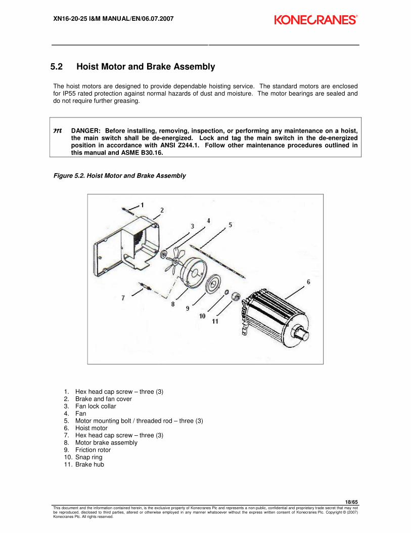
5.2 Hoist Motor and Brake Assembly
The hoist motors are designed to provide dependable hoisting service. The standard motors are enclosed for IP55 rated protection against normal hazards of dust and moisture. The motor bearings are sealed and do not require further greasing.
m DANGER: Before installing, removing, inspection, or performing any maintenance on a hoist, the main switch shall be de-energized. Lock and tag the main switch in the de-energized position in accordance with ANSI Z244.1. Follow other maintenance procedures outlined in this manual and ASME B30.16.
Figure 5.2. Hoist Motor and Brake Assembly
1. Hex head cap screw – three (3) 2. Brake and fan cover 3. Fan lock collar 4. Fan 5. Motor mounting bolt / threaded rod – three (3) 6. Hoist motor 7. Hex head cap screw – three (3) 8. Motor brake assembly 9. Friction rotor 10. Snap ring 11. Brake hub

XN16-20-25 I&M MANUAL/EN/06.07.2007
19/65 This document and the information contained herein, is the exclusive property of Konecranes Plc and represents a non-public, confidential and proprietary trade secret that may not be reproduced, disclosed to third parties, altered or otherwise employed in any manner whatsoever without the express written consent of Konecranes Plc. Copyright © (2007) Konecranes Plc. All rights reserved.
Remove Hoist Motor and Brake Assembly (refer to Figure 5.2)
1. Remove load from load block assembly. 2. Raise load block assembly to hoist body. Allow slack in chain to permit tying up bottom block
assembly to remove weight of bottom block assembly from load chain. 3. Remove and lockout power to the hoist. 4. Remove three-sided branding cover. 5. Remove three (3) screws (item 1) and take off Brake and Fan Cover (item 2). 6. Remove brake coil leads from terminals inside hoist electrical control enclosure. 7. Loosen brake cable gland on electrical control enclosure and pull out brake cable. 8. Remove hoist motor leads from K25 and K10 contactors located in hoist electrical control enclosure. 9. Loosen motor cable gland on electrical control enclosure and pull out motor leads. 10. Remove screws and remove electrical control enclosure from hoist motor. 11. Remove screw and remove mounting bracket from hoist motor. 12. Remove three lock nuts from threaded rods (item 5) and pull hoist motor and brake assembly out
away from gearbox.
Installing Hoist Motor and Brake Assembly (refer to Figure 5.2)
1. Mount hoist motor to gearbox making sure hoist motor is positioned properly. Push hoist motor into
gearbox until tight and threaded rods (item 5) are through end flange of hoist motor. 2. Use lock nuts to draw hoist motor in place against the gearbox. Tighten lock nuts evenly as the hoist
motor moves into place. 3. Mount brackets to hoist motor and tighten socket head cap screw. 4. Mount electrical control enclosure to hoist motor and tighten four (4) screws. 5. Insert hoist motor cable through motor cable gland on electrical control enclosure and reconnect
motor leads to K25 and K10 contactors. Tighten hoist motor cable gland. 6. Insert hoist motor brake leads through brake cable gland on electrical control enclosure and
reconnect hoist motor brake leads. Tighten hoist motor brake cable gland. 7. Recheck tightness of lock nuts holding hoist motor. 8. Mount end cap and tighten socket head cap screws. (Do not over-tighten.) 9. Replace three-sided branding panel. 10. Untie the load block assembly. 11. Unlock power and turn on. 12. Press “UP” button and check for proper phase rotation. If not correct, turn off power and change
position of two of the three power leads that were just reconnected. 13. If direction is correct, perform a no-load check and then a full load check per section 3.3 and 3.4
respectively.

XN16-20-25 I&M MANUAL/EN/06.07.2007
20/65 This document and the information contained herein, is the exclusive property of Konecranes Plc and represents a non-public, confidential and proprietary trade secret that may not be reproduced, disclosed to third parties, altered or otherwise employed in any manner whatsoever without the express written consent of Konecranes Plc. Copyright © (2007) Konecranes Plc. All rights reserved.
Hoist Motor Brake
The hoist motor brake is a D.C. electromagnetic disc brake and does not require adjustment. The brake brings the load to a smooth and quick stop and holds the load when the hoist motor is not energized. An energized coil releases the hoist motor brake and permits the raising and lowering of the load.
Figure 5.3. Hoist Motor Brake
1. Brake Spring 2. Brake Armature Plate 3. Friction Rotor 4. Brake Hub 5. Brake Adjusting Rod 6. Brake Mounting Screw 7. Screw 8. Wear Plate
AIR GAP
SNAP RING REPLACED WITH LOCK COLLAR
7
8
XN16-20-25 I&M MANUAL/EN/06.07.2007
21/65 This document and the information contained herein, is the exclusive property of Konecranes Plc and represents a non-public, confidential and proprietary trade secret that may not be reproduced, disclosed to third parties, altered or otherwise employed in any manner whatsoever without the express written consent of Konecranes Plc. Copyright © (2007) Konecranes Plc. All rights reserved.
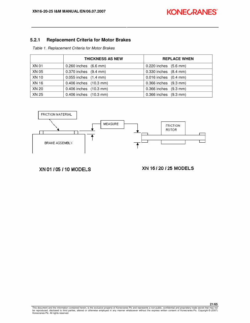
5.2.1 Replacement Criteria for Motor Brakes
Table 1. Replacement Criteria for Motor Brakes
THICKNESS AS NEW REPLACE WHEN
XN 01 0.260 inches (6.6 mm) 0.220 inches (5.6 mm)
XN 05 0.370 inches (9.4 mm) 0.330 inches (8.4 mm)
XN 10 0.055 inches (1.4 mm) 0.016 inches (0.4 mm)
XN 16 0.406 inches (10.3 mm) 0.366 inches (9.3 mm)
XN 20 0.406 inches (10.3 mm) 0.366 inches (9.3 mm)
XN 25 0.406 inches (10.3 mm) 0.366 inches (9.3 mm)

XN16-20-25 I&M MANUAL/EN/06.07.2007
22/65 This document and the information contained herein, is the exclusive property of Konecranes Plc and represents a non-public, confidential and proprietary trade secret that may not be reproduced, disclosed to third parties, altered or otherwise employed in any manner whatsoever without the express written consent of Konecranes Plc. Copyright © (2007) Konecranes Plc. All rights reserved.
���� NOTE: MAXIMUM ALLOWABLE GAP IS 0.5mm or 0.020 inches. Remove round plastic dust cap on the side of the brake assembly. Turn off power to hoist, insert gage pin of proper diameter to check motor brake gap. Recommend that a gage pin set be available with increments of 0.001” ranging from 0.015” to 0.020”.
���� Gap may be measured periodically to predict replacement based upon frequency of use. Replace the friction rotor when the gap reaches the maximum allowable dimension.
Removing Hoist Motor Brake (Refer to Figures 5.2 and 5.3)
1. Remove load from load block assembly. 2. Raise load block assembly to hoist body. Allow slack in chain to permit tying up bottom block
assembly to remove weight of bottom block assembly from load chain. 3. Remove and lockout power to the hoist. 4. Remove three-sided branding cover. 5. Remove three (3) screws (item 1- figure 5.2) and take off Brake and Fan Cover (item 2-figure 5.2). 6. Remove lock collar (see Figure 5.3) and remove fan. If needed, use two screwdrivers under hub to
pry fan loose. 7. Remove second retaining ring and pull out spacer. 8. Remove brake coil leads from terminals inside hoist electrical control enclosure. 9. Loosen brake cable gland and pull out brake cable as necessary. 10. Remove three (3) screws – Figure 5.3 - from brake magnetic assembly. Remove brake magnetic
assembly. 11. Remove motor brake friction rotor – item 3 – Figure 5.3. 12. Remove three (3) screws – item 7 – Figure 5.3 and remove wear plate item 8 – Figure 5.3.
Installing Hoist Motor Brake (Refer to Figures 5.2 and 5.3)
1. Check the voltage of the motor brake assembly. It must match the voltage of the motor. 2. Attach wear plate – item 8 – Figure 5.3 to hoist motor end flange and tighten three (3) screws item 7
– Figure 5.3 to recommended tightening torque – 6.6 lb-ft [9Nm]. 3. Slide friction rotor (item 3 – Figure 5.3) onto brake hub (item 4 – Figure 5.3). 4. Mount magnetic brake assembly (item 1 – Figure 5.3) and tighten three (3) screws (item 6 – Figure
5.3) to recommended tightening torque – 6.6 lb-ft [9 Nm]. 5. Insert spacer and install snap ring into groove just above spacer. 6. Mount fan (item 4 – Figure 5.2) and install lock collar just above fan hub. 7. Insert motor brake leads through brake cable gland on electrical control enclosure and reconnect
motor brake leads. Tighten motor cable gland. 8. Mount end cap and tighten three screws. (Do not over-tighten.) 9. Replace branding cover. 10. Turn on power. 11. Free the bottom block and make certain load chain is not twisted 12. Perform no-load test and load test per Sections 3.3 and 3.4 respectively.
XN16-20-25 I&M MANUAL/EN/06.07.2007
23/65 This document and the information contained herein, is the exclusive property of Konecranes Plc and represents a non-public, confidential and proprietary trade secret that may not be reproduced, disclosed to third parties, altered or otherwise employed in any manner whatsoever without the express written consent of Konecranes Plc. Copyright © (2007) Konecranes Plc. All rights reserved.
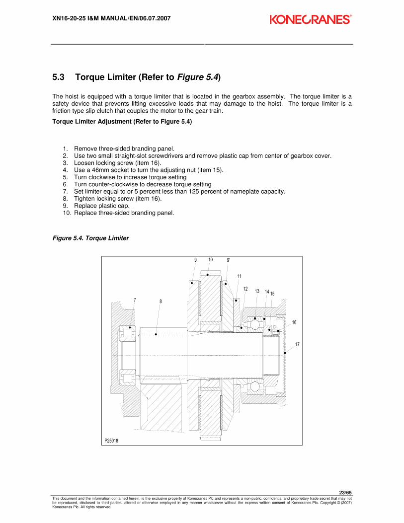
5.3 Torque Limiter (Refer to Figure 5.4)
The hoist is equipped with a torque limiter that is located in the gearbox assembly. The torque limiter is a safety device that prevents lifting excessive loads that may damage to the hoist. The torque limiter is a friction type slip clutch that couples the motor to the gear train.
Torque Limiter Adjustment (Refer to Figure 5.4)
1. Remove three-sided branding panel. 2. Use two small straight-slot screwdrivers and remove plastic cap from center of gearbox cover. 3. Loosen locking screw (item 16). 4. Use a 46mm socket to turn the adjusting nut (item 15). 5. Turn clockwise to increase torque setting 6. Turn counter-clockwise to decrease torque setting 7. Set limiter equal to or 5 percent less than 125 percent of nameplate capacity. 8. Tighten locking screw (item 16). 9. Replace plastic cap. 10. Replace three-sided branding panel.
Figure 5.4. Torque Limiter

XN16-20-25 I&M MANUAL/EN/06.07.2007
24/65 This document and the information contained herein, is the exclusive property of Konecranes Plc and represents a non-public, confidential and proprietary trade secret that may not be reproduced, disclosed to third parties, altered or otherwise employed in any manner whatsoever without the express written consent of Konecranes Plc. Copyright © (2007) Konecranes Plc. All rights reserved.
5.4 Load Chain
m CAUTION: A hoist SHALL NEVER be used if the load chain shows any evidence of mechanical damage or excessive wear. Never use the load chain as a sling. Use only original equipment chain as supplied by a factory authorized source. Improper load chain storage or installation can render the load chain unusable prior to the first lift.
5.5 Maintenance Inspection
A qualified person SHALL be designated to routinely conduct an in-depth inspection of the load chain (See Section 6 – Preventative Maintenance for schedule recommendations). This designated person SHALL inspect load chain using good judgment in evaluating the remaining service life. Any deterioration of load chain resulting in appreciable loss of original strength SHALL be noted and evaluated.
An in-depth inspection SHALL include a written record that is dated and signed by the inspector.

XN16-20-25 I&M MANUAL/EN/06.07.2007
25/65 This document and the information contained herein, is the exclusive property of Konecranes Plc and represents a non-public, confidential and proprietary trade secret that may not be reproduced, disclosed to third parties, altered or otherwise employed in any manner whatsoever without the express written consent of Konecranes Plc. Copyright © (2007) Konecranes Plc. All rights reserved.
Figure 5.5. Chain Dimensions
11 t
t
t
P25004
Ød
Measure the following chain dimensions at several points on chain: (Figure 5.5)
� Dimensions of one link ( d x t ) where, d = diameter and t = pitch � Length over 11 links ( 11 t )
Replace load chain if any one of these dimensions exceeds maximum allowed wear:
XN 16 XN 20 / 25
Maximum allowed wear: 9.0 x 27.0 chain 11.3 x 31.0
Minimum link diameter allowed (d): 0.319” [8.1 mm] 0.398” [10.1 mm]
Maximum pitch allowed (t): 1.114” [28.3 mm] 1.280” [32.5mm]
Maximum length allowed (11t): 11.929” [300 mm] 13.681” [347.5 mm]
NOTICE:
���� If load chain needs replaced, then inspect chain guide and chain (load) wheel on hoist and idler sprocket in 2-fall load block for excessive wear. A chain sprocket showing evidence of scored pockets or sharp edges generated from wear SHALL be replaced. A worn chain sprocket or idler sprocket can greatly reduce the life of load chain.

XN16-20-25 I&M MANUAL/EN/06.07.2007
26/65 This document and the information contained herein, is the exclusive property of Konecranes Plc and represents a non-public, confidential and proprietary trade secret that may not be reproduced, disclosed to third parties, altered or otherwise employed in any manner whatsoever without the express written consent of Konecranes Plc. Copyright © (2007) Konecranes Plc. All rights reserved.
5.6 Load Chain Specifications (see Figure 5.5)
Table 2. Load Chain Specifications
Hoist Type: XN 16 XN 20/LM25
Chain Specification: Load chain - 9.0 x 27.0 Load chain - 11.3 x 31.0
Chain type: Standard Standard
Diameter (ød) x pitch (t): 0.3543 x 1.0629 in [9.0 x 27.0 mm]
0.4449 x 1.2205 in [11.3 x 31.0 mm]
Length over 11 links (11t): 11.6929” [297 mm] 13.4251” [341 mm]
Class: DAT DAT
Grade: H8S or HE G80 RAS H8S or HE G80 RAS
Maximum working stress: 123.4 N/mm2 122.3 N/mm
2
Hardened surface: 580 or 700 HV 580 or 700 HV
Thickness: 0.18 to 0.45 mm 0.21 to 0.52 mm
Standard: DIN 5684 – 8 DIN 5684 - 8
Marking (10 x t): 1 or 16 1 or 16
H 8 S or A 8 H 8 S or A 8
Maximum working load, 1 fall:
3527 lbs. [1600 kg] 5511 lbs. [2500 kg]
Breaking load: 93 Kn 160 kN
Maximum breaking stress: 116,030 lbs/in2 (800 N/mm
2) 116,030 lbs/in
2 (800 N/mm
2)
Total breaking elongation: >10% min. >10% min.
Weight for 100 links: 1.8 kg 2.85 kg
5.7 Removing the Load Chain
1-FALL CHAIN
1. Remove load from hook block assembly. 2. Remove load block assembly from load chain. Some disassembly of 1-fall load block is required. 3. Attach the chain insert tool to the end of bottom block end of the chain. 4. Run hoist in “UP” direction until all of chain is in container. Stop the hoist with the insertion tool
remaining in the hoist ready for the new chain. 5. Remove chain container with all of old chain in chain container. 6. Remove fall stop from old chain and save for use with new chain.
2-FALL CHAIN
1. Remove load from hook block assembly. 2. Run hoist in “UP” direction until hook block assembly is about 1.0 foot [30cm] from hoist body. 3. Unfasten load chain from chain anchor mounted on hoist body. 4. Remove load block assembly from load chain by allowing chain to run through it. Attach the chain
insertion tool to the bottom block end of the chain. 5. Run hoist in “UP” direction until all of the chain is in the container. Stop the hoist with the insertion tool
remaining in the hoist ready for the new chain. 6. Remove chain container with old chain. 7. Remove fall stop from old chain and save for use with new chain.

XN16-20-25 I&M MANUAL/EN/06.07.2007
27/65 This document and the information contained herein, is the exclusive property of Konecranes Plc and represents a non-public, confidential and proprietary trade secret that may not be reproduced, disclosed to third parties, altered or otherwise employed in any manner whatsoever without the express written consent of Konecranes Plc. Copyright © (2007) Konecranes Plc. All rights reserved.
5.8 Installing the Load Chain Figure 5.6. Chain Installation Figure 5.7. Chain Orientation
1-FALL CHAIN INSTALLATION
1. Attach last link of chain onto hook of CHAIN INSERTION TOOL (item 1, Figure 5.6). 2. If the insertion tool is not in the hoist (removal procedure), insert other end of CHAIN INSERTION TOOL
into chain opening closest to chain container side.
m CAUTION: Make sure the chain weld on chain link faces inward toward chain wheel pocket on hoist load sprocket. See Figure 5.7.
3. Run hoist “UP” in slow speed to feed chain through chain sprocket and out other side. 4. Attach fall stop at least 6.0 inches [150 mm] from end of chain (chain container side). Attach load block
assembly on other end of load chain. Refer to Figure 5.8 for details. 5. Make sure that load chain is not twisted or deformed. 6. Attach chain container.

XN16-20-25 I&M MANUAL/EN/06.07.2007
28/65 This document and the information contained herein, is the exclusive property of Konecranes Plc and represents a non-public, confidential and proprietary trade secret that may not be reproduced, disclosed to third parties, altered or otherwise employed in any manner whatsoever without the express written consent of Konecranes Plc. Copyright © (2007) Konecranes Plc. All rights reserved.
2-FALL CHAIN INSTALLATION
1. If the chain insertion tool is not in the hoist (removal procedure), attach last link of chain onto hook of CHAIN INSERTION TOOL (item 1, Figure 5.6).
2. Insert other end of CHAIN INSERTION TOOL into chain opening closest to chain container.
m CAUTION: For a 2-Fall load block assembly, make sure the chain weld on chain link faces inward toward chain wheel pocket on hoist and away from idler sprocket of hook block assembly. See Figure 5.7. Follow steps outlined below:
3. Run hoist in slow speed to feed chain through chain sprocket. Continue running until about 2.0 feet
[60cm] of chain is available out the other side. 4. Slide chain onto idler sprocket of load block making sure not to twist chain while inserting it. Link
weld must face away from idler sprocket on load block assembly. 5. Attach chain anchor and chain to hoist body. Tighten chain anchor bolts per recommended torque
settings in Section 6.4. 6. Attach fall stop 6.0 inches [150 mm] from end of chain (chain container side). See Figure 5.6 for
details. 7. Make sure that chain is not twisted or kinked. 8. Attach chain container
After chain installation:
1. Without a load, run chain up and down a few times to make sure load chain is not twisted. If so,
remove chain twist. 2. Lubricate load chain.
XN16-20-25 I&M MANUAL/EN/06.07.2007
29/65 This document and the information contained herein, is the exclusive property of Konecranes Plc and represents a non-public, confidential and proprietary trade secret that may not be reproduced, disclosed to third parties, altered or otherwise employed in any manner whatsoever without the express written consent of Konecranes Plc. Copyright © (2007) Konecranes Plc. All rights reserved.
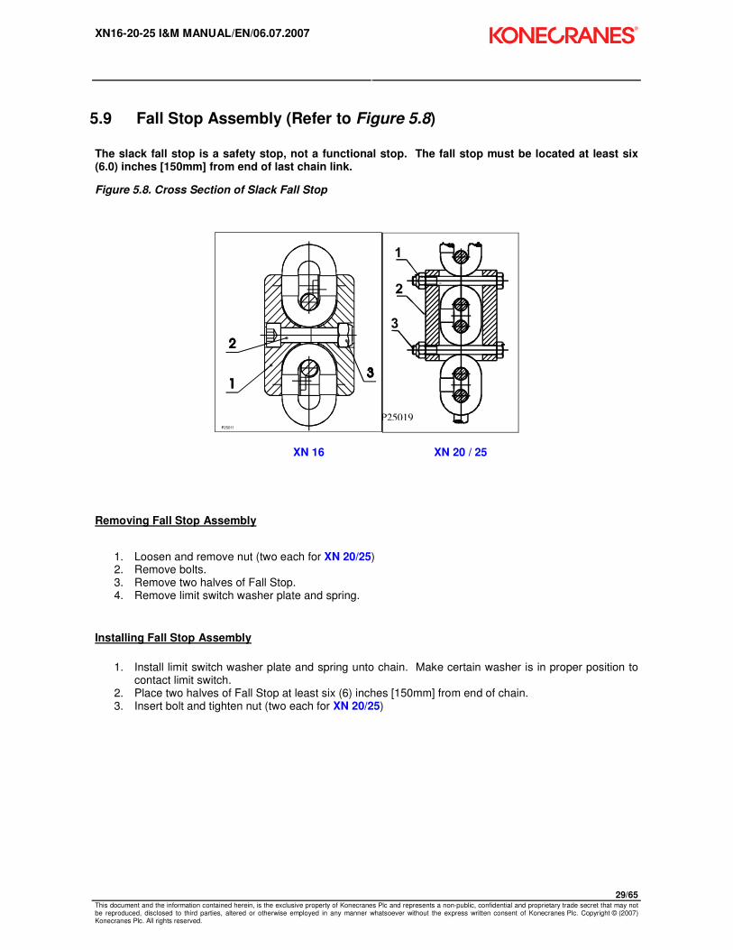
5.9 Fall Stop Assembly (Refer to Figure 5.8)
The slack fall stop is a safety stop, not a functional stop. The fall stop must be located at least six (6.0) inches [150mm] from end of last chain link.
Figure 5.8. Cross Section of Slack Fall Stop
P25019
XN 16 XN 20 / 25
Removing Fall Stop Assembly
1. Loosen and remove nut (two each for XN 20/25) 2. Remove bolts. 3. Remove two halves of Fall Stop. 4. Remove limit switch washer plate and spring.
Installing Fall Stop Assembly
1. Install limit switch washer plate and spring unto chain. Make certain washer is in proper position to
contact limit switch. 2. Place two halves of Fall Stop at least six (6) inches [150mm] from end of chain. 3. Insert bolt and tighten nut (two each for XN 20/25)
XN16-20-25 I&M MANUAL/EN/06.07.2007
30/65 This document and the information contained herein, is the exclusive property of Konecranes Plc and represents a non-public, confidential and proprietary trade secret that may not be reproduced, disclosed to third parties, altered or otherwise employed in any manner whatsoever without the express written consent of Konecranes Plc. Copyright © (2007) Konecranes Plc. All rights reserved.
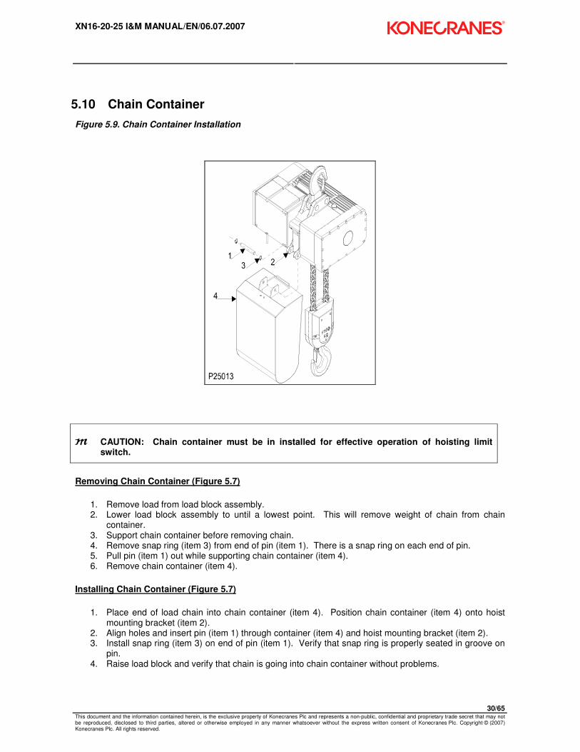
5.10 Chain Container
Figure 5.9. Chain Container Installation
m CAUTION: Chain container must be in installed for effective operation of hoisting limit switch.
Removing Chain Container (Figure 5.7)
1. Remove load from load block assembly. 2. Lower load block assembly to until a lowest point. This will remove weight of chain from chain
container. 3. Support chain container before removing chain. 4. Remove snap ring (item 3) from end of pin (item 1). There is a snap ring on each end of pin. 5. Pull pin (item 1) out while supporting chain container (item 4). 6. Remove chain container (item 4).
Installing Chain Container (Figure 5.7)
1. Place end of load chain into chain container (item 4). Position chain container (item 4) onto hoist
mounting bracket (item 2). 2. Align holes and insert pin (item 1) through container (item 4) and hoist mounting bracket (item 2). 3. Install snap ring (item 3) on end of pin (item 1). Verify that snap ring is properly seated in groove on
pin. 4. Raise load block and verify that chain is going into chain container without problems.
XN16-20-25 I&M MANUAL/EN/06.07.2007
31/65 This document and the information contained herein, is the exclusive property of Konecranes Plc and represents a non-public, confidential and proprietary trade secret that may not be reproduced, disclosed to third parties, altered or otherwise employed in any manner whatsoever without the express written consent of Konecranes Plc. Copyright © (2007) Konecranes Plc. All rights reserved.
5.11 Upper and Lower Travel Safety Limit Switch
The Upper and Lower Travel Limit Switch is an automatic reset type switch and connected to the control circuit. The switch housing is recessed into the underside of hoist body.
m CAUTION: The primary limit device that controls the upper limit of travel is an emergency device only. It shall not be used as an operational means to stop travel during normal operations. Do not permit continuous contact between the hoist body and the load block / fall stop assembly.
The hook block activates the upper limit switch as it contacts the limit switch that is located on bottom side of hoist body. Once the switch is activated, the “UP” circuit is opened. The fall stop activates the lower limit switch when hook block is lowered to its lowest travel position. The limit switch is activated and opens the “DOWN” circuit.
The lower limit position is adjustable between the lowest travel and maximum lift. It is adjusted by repositioning the fall stop assembly on free end of load chain. The fall stop SHALL always be located at least six (6) inches [150mm] from end of last chain link. The upper limit position is adjustable only when an additional fall stop assembly is added between the hook block assembly and the hoist body.

XN16-20-25 I&M MANUAL/EN/06.07.2007
32/65 This document and the information contained herein, is the exclusive property of Konecranes Plc and represents a non-public, confidential and proprietary trade secret that may not be reproduced, disclosed to third parties, altered or otherwise employed in any manner whatsoever without the express written consent of Konecranes Plc. Copyright © (2007) Konecranes Plc. All rights reserved.
5.12 Upper and Lower Rotary Travel Limit Switch
The rotary limit switch is adjustable and provides over-travel protection for the upper and lower limits of hoist travel. The limit switch is connected to the control circuit.
���� Note: Rotary limit switch assembly cannot be added to a Hoist. The Hoist must have the rotary limit switch assembly provided at time of initial production.
Adjustment
The position of the air-gap between the two discs (red – gray) determines the stopping place. This position can be found by gently turning the two discs. The length of air gap determines length of reset play in opposite direction.
Figure 5.9
To reset the rotary limit once it has tripped, the load block assembly must travel approximately 11” [27cm] in opposite direction.
XN16-20-25 I&M MANUAL/EN/06.07.2007
33/65 This document and the information contained herein, is the exclusive property of Konecranes Plc and represents a non-public, confidential and proprietary trade secret that may not be reproduced, disclosed to third parties, altered or otherwise employed in any manner whatsoever without the express written consent of Konecranes Plc. Copyright © (2007) Konecranes Plc. All rights reserved.
5.13 Hooks
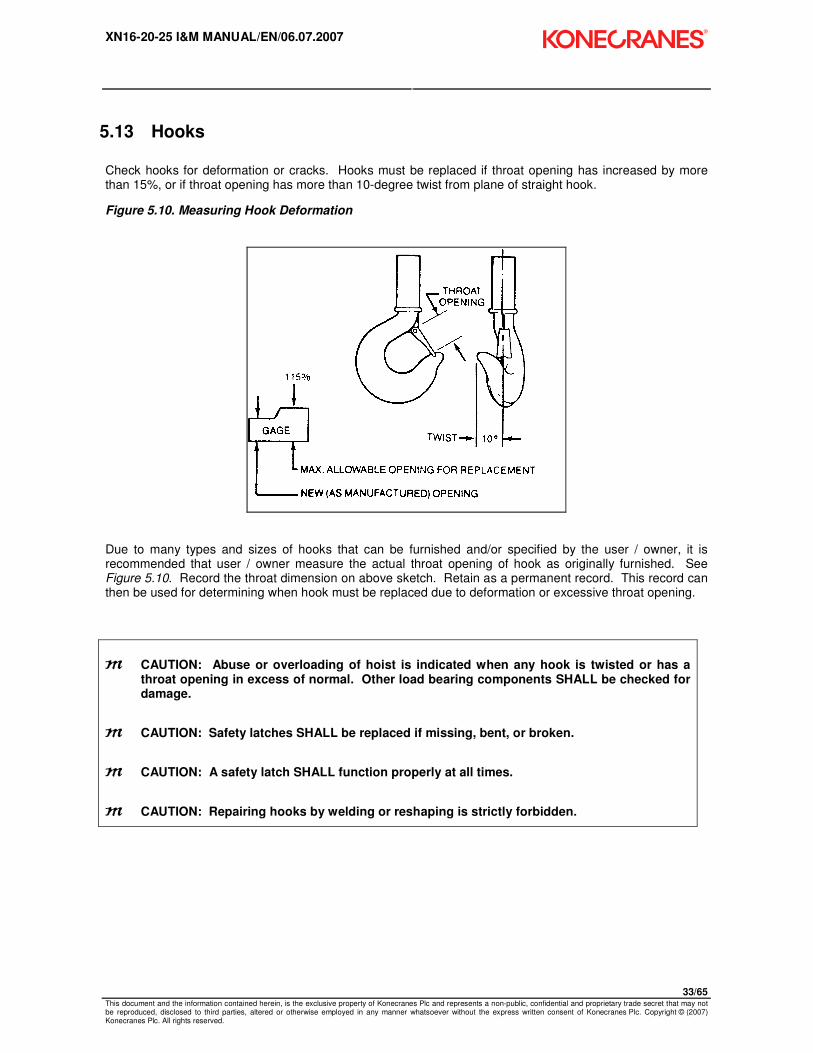
Check hooks for deformation or cracks. Hooks must be replaced if throat opening has increased by more than 15%, or if throat opening has more than 10-degree twist from plane of straight hook.
Figure 5.10. Measuring Hook Deformation
Due to many types and sizes of hooks that can be furnished and/or specified by the user / owner, it is recommended that user / owner measure the actual throat opening of hook as originally furnished. See Figure 5.10. Record the throat dimension on above sketch. Retain as a permanent record. This record can then be used for determining when hook must be replaced due to deformation or excessive throat opening.
m CAUTION: Abuse or overloading of hoist is indicated when any hook is twisted or has a throat opening in excess of normal. Other load bearing components SHALL be checked for damage.
m CAUTION: Safety latches SHALL be replaced if missing, bent, or broken.
m CAUTION: A safety latch SHALL function properly at all times.
m CAUTION: Repairing hooks by welding or reshaping is strictly forbidden.

XN16-20-25 I&M MANUAL/EN/06.07.2007
34/65 This document and the information contained herein, is the exclusive property of Konecranes Plc and represents a non-public, confidential and proprietary trade secret that may not be reproduced, disclosed to third parties, altered or otherwise employed in any manner whatsoever without the express written consent of Konecranes Plc. Copyright © (2007) Konecranes Plc. All rights reserved.
5.14 Hook Inspection
The wear on the top hook and the load hook shall be checked routinely. Measure the throat opening (dimension a2). If the throat opening exceeds the maximum opening allowed (1.15 x a2), replace the hook. Damaged safety latches shall be replaced immediately.
Maximum throat opening allowed:
Hook class: 05T 08T 1T 16T Top Hook
Maximum allowed opening:
1.54” [39mm]
1.69” [43mm]
1.81” [46mm]
2.01” [51mm]
2.13” [54mm]

XN16-20-25 I&M MANUAL/EN/06.07.2007
35/65 This document and the information contained herein, is the exclusive property of Konecranes Plc and represents a non-public, confidential and proprietary trade secret that may not be reproduced, disclosed to third parties, altered or otherwise employed in any manner whatsoever without the express written consent of Konecranes Plc. Copyright © (2007) Konecranes Plc. All rights reserved.
5.15 Hook Dimensions
Figure 5.11. Hook Dimensions
Table 3. Hook Dimensions
Hook Data Dimensions inch / [mm]
Cap Ton
Cap
kg
Test
lbs
Hoist
Fall
Hook
Class øM ø a1 øa2 a3 b1 b2 e1 h1 h2 t1 t2
øa2
max
1 1/2 1600 7055 XN 16
1 05 T
0.787
[20]
1.693
[43]
1.339
[34]
1.929
[49]
1.412
[29]
0.945
[24]
4.134
[105]
1.457
[37]
1.220
[31]
1.693
[43]
0.551
[14]
1.535
[39]
2 2000 8818 XN 20
1 08 T
0.945
[24]
1.890
[48]
1.496
[38]
2.125
[54]
1.378
[35]
1.142
[29]
4.528
[115]
1.732
[44]
1.457
[37]
2.087
[53]
0.709
[18]
1.693
[43]
2 1/2 2500 11023 XN 25
1 08 T
0.945
[24]
1.890
[48]
1.496
[38]
2.125
[54]
1.378
[35]
1.142
[29]
4.528
[115]
1.732
[44]
1.457
[37]
2.087
[53]
0.709
[18]
1.693
[43]
XN 25
1
08 T
0.945
[24]
1.890
[48]
1.496
[38]
2.125
[54]
1.378
[35]
1.142
[29]
4.528
[115]
1.732
[44]
1.457
[37]
2.087
[53]
0.709
[18]
1.693
[43] 3 3200 14110
XN 16
2 1 T
0.945
[24]
1.969
[50]
1.575
[40]
2.244
[57]
1.496
[38]
1.26
[32]
4.724
[120]
1.89
[48]
1.575
[40]
2.323
[59]
0.945
[24]
1.811
[46]
4 4000 17637 XN 20
2 16 T
1.181
[30]
2.205
[56]
1.772
[45]
2.520
[64]
1.772
[45]
1.496
[38]
5.315
[135]
2.205
[56]
1.890
[48]
2.638
[67]
0.945
[24]
2.008
[51]
5 5000 22046 XN 25
2 16 T
1.181
[30]
2.205
[56]
1.772
[45]
2.520
[64]
1.772
[45]
1.496
[38]
5.315
[135]
2.205
[56]
1.890
[48]
2.638
[67]
0.945
[24]
2.008
[51]
Mark: ISO 2766
DIN model number: 15401
DIN 15400 class: T
DIN 15401 material: 35 CD 4

XN16-20-25 I&M MANUAL/EN/06.07.2007
36/65 This document and the information contained herein, is the exclusive property of Konecranes Plc and represents a non-public, confidential and proprietary trade secret that may not be reproduced, disclosed to third parties, altered or otherwise employed in any manner whatsoever without the express written consent of Konecranes Plc. Copyright © (2007) Konecranes Plc. All rights reserved.
5.16 Top Hook
Figure 5.12. Top Hook Orientation
P25020
m CAUTION: Before removing Top Hook, de-energize the power to the hoist per ANSI Z244.1 and make certain that any load is removed from the load hook. Also support the total weight of the hoist, including chain, prior to removing the Top Hook.
Removing Top Hook
1. Place hoist on workbench. Protect limit switches on bottom of hoist. 2. There are two pins holding top hook in place. Remove retaining ring and washer on one end of each
pin. 3. Pull pins out and remove hook. Keep washers and snap rings.
m CAUTION: Proper installation of top hook is critical for hoist balance.
Installing Top Hook
1. Place hoist on workbench. Protect limit switches on bottom of hoist. 2. Verify if hoist is 1-fall or 2-fall configuration. The hook is symmetrical and can be positioned two
different directions. It is important to place top hook is correct position. Verify position of top hook with the above drawing.
3. Place top hook in location. Install pins and retaining hardware. Verify that a snap ring and washer is securely in place on each end.
CHAIN CONTAINER BRACKET

XN16-20-25 I&M MANUAL/EN/06.07.2007
37/65 This document and the information contained herein, is the exclusive property of Konecranes Plc and represents a non-public, confidential and proprietary trade secret that may not be reproduced, disclosed to third parties, altered or otherwise employed in any manner whatsoever without the express written consent of Konecranes Plc. Copyright © (2007) Konecranes Plc. All rights reserved.
5.17 Controls
The two-speed hoists are available for 208, 230, 460, 575 Volt - three-phase – 60 hertz power supplies. The controls of the two-speed hoists are NOT re-connectable because the hoist motors are voltage specific.
Note: The controls of the motorized trolley drive are not voltage re-connectable. Consult the motorized trolley manual if a voltage changeover is required.
Control Circuit Fuses
The PC board control on the hoist includes a fuse (F100) for control circuit protection.
Table 4. Control Circuit Fuse
Control Voltage Size
115 VAC 1.25 A
48 VAC 1.25 A
Table 5. Control Circuit Components, Terminals, and Connections.
Power & Motor Supply Pushbutton Function
L1 Hoist Supply
X23 Plug
Pin No: Terminal
L2 Hoist Supply Common X23: 1 1-2 Thermal protection
L3 Hoist Supply Up X23: 2 2-3 Upper limit switch
K21-2 (-) Brake Down X23: 3 4-5 Lower limit switch
K21-4 (+) Brake Hoist Fast X23: 4 ID Description
K10-1 U1-U2 Motor Supply
E-Stop X23: 5 K10 E-stop contactor
K25-R3 1V Motor Supply Trolley Right X23: 6 K21 Up contactor
K25-3 2V Motor Supply Trolley Left X23: 7 K22 Down contactor
K25-R1 1W Motor Supply Trolley Fast X23: 8 K25 Hoist fast contactor
Ground T100 Transformer
PE Motor Terminal F100 Fuse
PE K10
X24 Plug
Pin No:
PE Trolley Connection X1: 9 Control voltage
X24: 1
PE Power Supply X1: 10 SD: low speed X24: 2
X1: 8 F: Trolley Fast X24: 3
X1: 7 D1: Trolley Rev
X24: 4
X1: 6 D2: Trolley Fwd
X24: 5

XN16-20-25 I&M MANUAL/EN/06.07.2007
38/65 This document and the information contained herein, is the exclusive property of Konecranes Plc and represents a non-public, confidential and proprietary trade secret that may not be reproduced, disclosed to third parties, altered or otherwise employed in any manner whatsoever without the express written consent of Konecranes Plc. Copyright © (2007) Konecranes Plc. All rights reserved.
Control Panel Layout
Figure 5.13. Printed Control Circuit (2 Lifting Speeds with Emergency Stop)

XN16-20-25 I&M MANUAL/EN/06.07.2007
39/65 This document and the information contained herein, is the exclusive property of Konecranes Plc and represents a non-public, confidential and proprietary trade secret that may not be reproduced, disclosed to third parties, altered or otherwise employed in any manner whatsoever without the express written consent of Konecranes Plc. Copyright © (2007) Konecranes Plc. All rights reserved.
5.18 Two Speed – Three Phase – 208 / 230 / 460 Volt – Power Circuit
XN16-20-25 I&M MANUAL/EN/06.07.2007
40/65 This document and the information contained herein, is the exclusive property of Konecranes Plc and represents a non-public, confidential and proprietary trade secret that may not be reproduced, disclosed to third parties, altered or otherwise employed in any manner whatsoever without the express written consent of Konecranes Plc. Copyright © (2007) Konecranes Plc. All rights reserved.
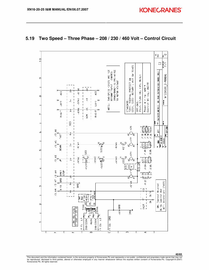
5.19 Two Speed – Three Phase – 208 / 230 / 460 Volt – Control Circuit
XN16-20-25 I&M MANUAL/EN/06.07.2007
41/65 This document and the information contained herein, is the exclusive property of Konecranes Plc and represents a non-public, confidential and proprietary trade secret that may not be reproduced, disclosed to third parties, altered or otherwise employed in any manner whatsoever without the express written consent of Konecranes Plc. Copyright © (2007) Konecranes Plc. All rights reserved.
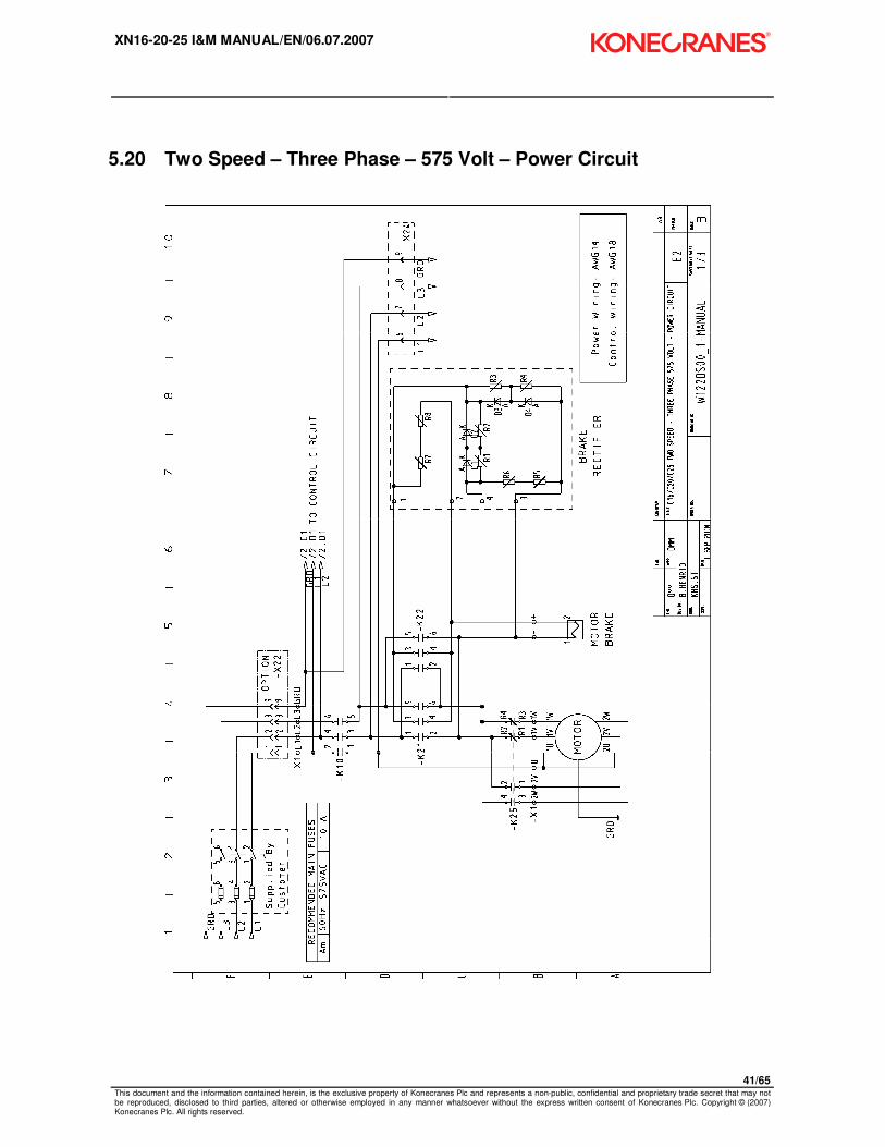
5.20 Two Speed – Three Phase – 575 Volt – Power Circuit
XN16-20-25 I&M MANUAL/EN/06.07.2007
42/65 This document and the information contained herein, is the exclusive property of Konecranes Plc and represents a non-public, confidential and proprietary trade secret that may not be reproduced, disclosed to third parties, altered or otherwise employed in any manner whatsoever without the express written consent of Konecranes Plc. Copyright © (2007) Konecranes Plc. All rights reserved.
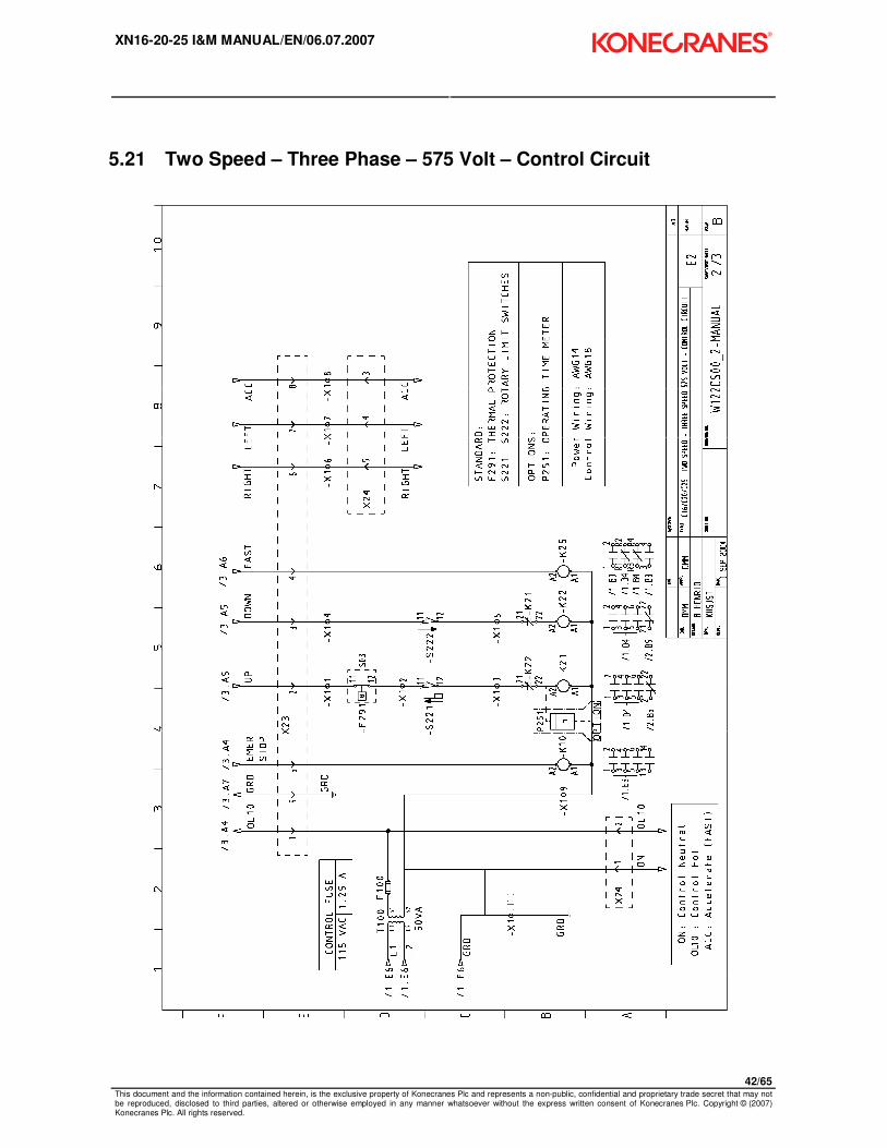
5.21 Two Speed – Three Phase – 575 Volt – Control Circuit

XN16-20-25 I&M MANUAL/EN/06.07.2007
43/65 This document and the information contained herein, is the exclusive property of Konecranes Plc and represents a non-public, confidential and proprietary trade secret that may not be reproduced, disclosed to third parties, altered or otherwise employed in any manner whatsoever without the express written consent of Konecranes Plc. Copyright © (2007) Konecranes Plc. All rights reserved.
5.22 Wiring Diagram – 3 Button – Push Button

XN16-20-25 I&M MANUAL/EN/06.07.2007
44/65 This document and the information contained herein, is the exclusive property of Konecranes Plc and represents a non-public, confidential and proprietary trade secret that may not be reproduced, disclosed to third parties, altered or otherwise employed in any manner whatsoever without the express written consent of Konecranes Plc. Copyright © (2007) Konecranes Plc. All rights reserved.
5.23 Wiring Diagram – 5 Button – Push Button

XN16-20-25 I&M MANUAL/EN/06.07.2007
45/65 This document and the information contained herein, is the exclusive property of Konecranes Plc and represents a non-public, confidential and proprietary trade secret that may not be reproduced, disclosed to third parties, altered or otherwise employed in any manner whatsoever without the express written consent of Konecranes Plc. Copyright © (2007) Konecranes Plc. All rights reserved.
5.24 Wiring Diagram – 7 Button – Push Button

XN16-20-25 I&M MANUAL/EN/06.07.2007
46/65 This document and the information contained herein, is the exclusive property of Konecranes Plc and represents a non-public, confidential and proprietary trade secret that may not be reproduced, disclosed to third parties, altered or otherwise employed in any manner whatsoever without the express written consent of Konecranes Plc. Copyright © (2007) Konecranes Plc. All rights reserved.
6 PREVENTATIVE MAINTENANCE
6.1 Maintenance and Inspection Table
Table 6. Maintenance Schedule
INSPECTION CHECK INTERVAL QUALIFIED PERSON
BRAKE OPERATION FOR HOLDING AND RELEASING DAILY OPERATOR
LOAD CHAIN FOR DAMAGE DAILY OPERATOR
SUSPENSION SUPPORT OF P/ B ASSEMBLY DAILY OPERATOR
CLEANLINESS & LUBRICATION OF LOAD CHAIN MONTHLY OPERATOR
UPPER / LOWER LIMIT SWITCHES DAILY OPERATOR
CHECK LOAD CHAIN FOR WEAR – MEASURE AND RECORD EVERY 3 MONTHS QUALIFIED INSPECTOR
CHECK HOOKS FOR WEAR MEASURE AND RECORD EVERY 3 MONTHS QUALIFIED INSPECTOR
CHECK LOAD BLOCK HARDWARE TO VERIFY TIGHTNESS EVERY 3 MONTHS OPERATOR
CHECK TOP HOOK / COUPLING HARDWARE FOR TIGHTNESS EVERY 3 MONTHS OPERATOR
CHECK SLIP CLUTCH & HOIST BRAKE ADJUSTMENT EVERY 3 -6 MONTHS QUALIFIED MECHANIC
CHECK LUBRICATION OF OPEN WHEEL GEARING EVERY 3 -6 MONTHS QUALIFIED MECHANIC
CHECK WIRE TERMINALS TIGHTNESS SEMI-ANNUALLY QUALIFIED MECHANIC
LUBRICATE 2-FALL LOAD BLOCK SPROCKET ANNUALLY OPERATOR
CHECK ALL HARDWARE FOR TIGHTNESS AND CORROSION ANNUALLY QUALIFIED MECHANIC
CLEAN MOTOR COOLING FINS ANNUALLY QUALIFIED MECHANIC
LUBRICATE ALL GEARING ANNUALLY QUALIFIED MECHANIC
INSPECT LOAD BLOCK THRUST BEARING ANNUALLY QUALIFIED MECHANIC
m CAUTION: INSPECTION AND MAINTENANCE INTERVALS SHOULD BE ADJUSTED BASED UPON OWNER / USER KNOWLEDGE OF APPLICATION, ENVIRONMENT, AND FREQUENCY OF USE TO PREVENT DAMAGE TO PEOPLE, EQUIPMENT, AND FACILITIES.

XN16-20-25 I&M MANUAL/EN/06.07.2007
47/65 This document and the information contained herein, is the exclusive property of Konecranes Plc and represents a non-public, confidential and proprietary trade secret that may not be reproduced, disclosed to third parties, altered or otherwise employed in any manner whatsoever without the express written consent of Konecranes Plc. Copyright © (2007) Konecranes Plc. All rights reserved.
6.2 Lubrication
Table 7. Lubrication Specifications
LUBRICATION
POINT SPECIFICATIONS ACCEPTABLE LUBRICANTS QUANTITY
Chain Oil or Liquid grease Chain lubricating fluid (Ceplattyn or similar) EP-90
As required
Idler sprocket
Slide bearing + bearing
Grease (without MoS2)
KP 2 (DIN 51 502)
Soap-based lithium
Approx. drip point + 500°F
Worked penetration 509-563°F
Operating temperature - 4°F - +266°F
BP: BP Energrease LS - EP 2
Esso: Unirex N2
Mobil: Mobilgrease HP
Shell: Shell Alvanio EP Grease 2
As required
Gears Oil EP220 Mobil: L-CKC220
BP: Energol XP220
Shell: Omala 150/220
1.6 liters
1 ¾ qts
Open Wheel Gearing: EP1 Mobilux or equivalent.
XN16-20-25 I&M MANUAL/EN/06.07.2007
48/65 This document and the information contained herein, is the exclusive property of Konecranes Plc and represents a non-public, confidential and proprietary trade secret that may not be reproduced, disclosed to third parties, altered or otherwise employed in any manner whatsoever without the express written consent of Konecranes Plc. Copyright © (2007) Konecranes Plc. All rights reserved.
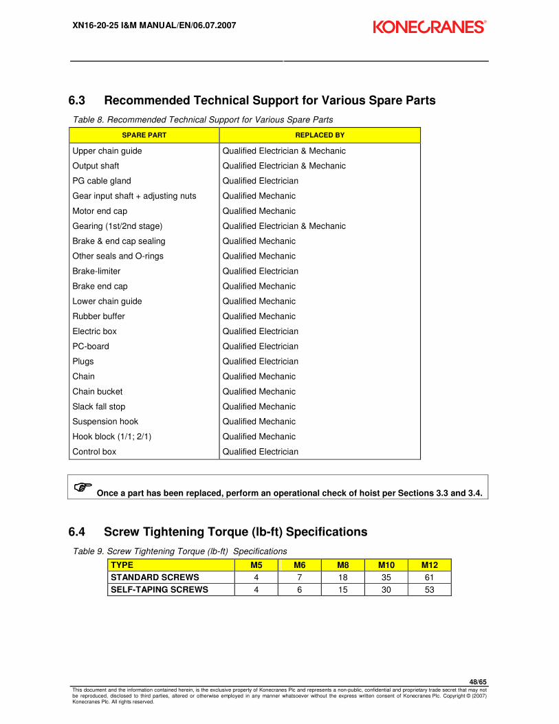
6.3 Recommended Technical Support for Various Spare Parts
Table 8. Recommended Technical Support for Various Spare Parts
SPARE PART REPLACED BY
Upper chain guide
Output shaft
PG cable gland
Gear input shaft + adjusting nuts
Motor end cap
Gearing (1st/2nd stage)
Brake & end cap sealing
Other seals and O-rings
Brake-limiter
Brake end cap
Lower chain guide
Rubber buffer
Electric box
PC-board
Plugs
Chain
Chain bucket
Slack fall stop
Suspension hook
Hook block (1/1; 2/1)
Control box
Qualified Electrician & Mechanic
Qualified Electrician & Mechanic
Qualified Electrician
Qualified Mechanic
Qualified Mechanic
Qualified Electrician & Mechanic
Qualified Mechanic
Qualified Mechanic
Qualified Electrician
Qualified Mechanic
Qualified Mechanic
Qualified Mechanic
Qualified Electrician
Qualified Electrician
Qualified Electrician
Qualified Mechanic
Qualified Mechanic
Qualified Mechanic
Qualified Mechanic
Qualified Mechanic
Qualified Electrician
���� Once a part has been replaced, perform an operational check of hoist per Sections 3.3 and 3.4.
6.4 Screw Tightening Torque (lb-ft) Specifications
Table 9. Screw Tightening Torque (lb-ft) Specifications
TYPE M5 M6 M8 M10 M12
STANDARD SCREWS 4 7 18 35 61
SELF-TAPING SCREWS 4 6 15 30 53

XN16-20-25 I&M MANUAL/EN/06.07.2007
49/65 This document and the information contained herein, is the exclusive property of Konecranes Plc and represents a non-public, confidential and proprietary trade secret that may not be reproduced, disclosed to third parties, altered or otherwise employed in any manner whatsoever without the express written consent of Konecranes Plc. Copyright © (2007) Konecranes Plc. All rights reserved.
6.5 Troubleshooting
Table 10. Troubleshooting
PROBLEM POSSIBLE CAUSE POSSIBLE SOLUTION
Hoist does not lift or lower load Emergency stop button is activated
Deactivate button
Blown fuse Replace the fuse
Motor thermal protection activated
Allow motor to cool down
Pendant plug pin pushed out Reinstall plug pin
Contactor terminal screws loose Tighten screws
Mainline switch shut off Turn switch on
Hoist does not lift load Overload condition Reduce load
Slip clutch worn or incorrectly adjusted
Replace wear items or readjust slip clutch torque
Brake not releasing
Check brake coil resistance.
Check air gap setting. Adjust if necessary.
Check rectifier output voltage.
Load drifts more than 4 inches [100mm]
Brake lining worn
Air gap on brake is too wide
Replace wear items as necessary
Adjust air gap setting
Travel direction does not correspond to that indicated on push button
Power supply incorrectly connected
See SECTION 2
Abnormal noises while lifting or lowering
Load chain and its components are not lubricated
Clean and lubricate load chain.
Load chain is worn Replace chain
Chain wheel or chain guide is worn
Replace chain wheel or chain guide
Idler sprocket is worn Replace idler sprocket
A supply phase is missing Connect the three phases
Twist or kink in load chain Remove twist or kink
XN16-20-25 I&M MANUAL/EN/06.07.2007
50/65 This document and the information contained herein, is the exclusive property of Konecranes Plc and represents a non-public, confidential and proprietary trade secret that may not be reproduced, disclosed to third parties, altered or otherwise employed in any manner whatsoever without the express written consent of Konecranes Plc. Copyright © (2007) Konecranes Plc. All rights reserved.
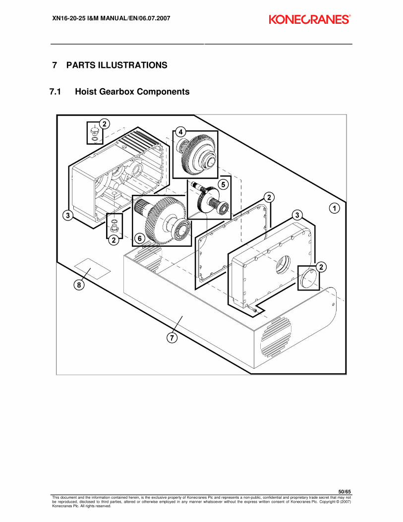
7 PARTS ILLUSTRATIONS
7.1 Hoist Gearbox Components

XN16-20-25 I&M MANUAL/EN/06.07.2007
51/65 This document and the information contained herein, is the exclusive property of Konecranes Plc and represents a non-public, confidential and proprietary trade secret that may not be reproduced, disclosed to third parties, altered or otherwise employed in any manner whatsoever without the express written consent of Konecranes Plc. Copyright © (2007) Konecranes Plc. All rights reserved.
Table 11. Hoist Gearbox Parts List
ITEM PART NUMBER DESCRIPTION QTY
2269955 C16 BODY ( TS ) 200-230V 1+3+4 1
2269956 C16 BODY ( TS ) 460V 1+3+4 1
2269957 C16 BODY ( TS ) 575V 1+3+4 1
2279965 C20 BODY ( TS ) 200-230V 1+3+4 1
2279966 C20 BODY ( TS ) 460V 1+3+4 1
2279967 C20 BODY ( TS ) 575V 1+3+4 1
2279968 C25 BODY ( TS ) 200-230V 1+3+4 1
2279969 C25 BODY ( TS ) 460V 1+3+4 1
2269955 C16 BODY ( TS ) 200-230V 1+3+4 1
1 2260500 C16/20 GEARBOX ASSEMBLY – 113:1 – 32 / 8 FPM 1
1 2270500 C25 GEARBOX ASSEMBLY – 144.2:1 – 24 / 6 FPM 1
2 2279923 SEAL SET 1
3 2270000 GEAR CASE HOUSING 1
4 2279904 GEAR SET – 2nd
REDUCTION 1
5a 2279902 GEAR SET – 1st REDUCTION – C16/20 1
5b 2279903 GEAR SET – 1st REDUCTION – C25 1
6 2279905 GEAR SET – 3rd
REDUCTION 1
7 52340377 XN BRANDING BAND 1
8 2213309002 HOIST BODY CAPACITY STICKER – ½ TON 1
8 2213309003 HOIST BODY CAPACITY STICKER – 1 TON 1
8 2213309004 HOIST BODY CAPACITY STICKER – 2.0 TON 1
8 2213309008 HOIST BODY CAPACITY STICKER – 500 KG 1
8 2213309009 HOIST BODY CAPACITY STICKER – 1000 KG 1
8 2213309010 HOIST BODY CAPACITY STICKER – 2000 KG 1
8 2213309011 HOIST BODY CAPACITY STICKER – 3200 KG 1
8 2213309012 HOIST BODY CAPACITY STICKER – 5000 KG 1
8 2213309013 HOIST BODY CAPACITY STICKER – 5.0 TON 1
8 2213309014 HOIST BODY CAPACITY STICKER – 1.5 TON 1
8 2213309015 HOIST BODY CAPACITY STICKER – 2.5 TON 1
8 2213309016 HOIST BODY CAPACITY STICKER – 1500 KG 1
8 2213309017 HOIST BODY CAPACITY STICKER – 2500 KG 1
8 2213309019 HOIST BODY CAPACITY STICKER – 4000 KG 1
- 2213445001 ELECTRICAL WIRING INFORMATION STICKER 1
- 2213445002 ELECTRICAL HAZARD WARNING STICKER 1

XN16-20-25 I&M MANUAL/EN/06.07.2007
52/65 This document and the information contained herein, is the exclusive property of Konecranes Plc and represents a non-public, confidential and proprietary trade secret that may not be reproduced, disclosed to third parties, altered or otherwise employed in any manner whatsoever without the express written consent of Konecranes Plc. Copyright © (2007) Konecranes Plc. All rights reserved.
7.2 C16 / C20 / C25 Hoist Motor & Brake Assembly

XN16-20-25 I&M MANUAL/EN/06.07.2007
53/65 This document and the information contained herein, is the exclusive property of Konecranes Plc and represents a non-public, confidential and proprietary trade secret that may not be reproduced, disclosed to third parties, altered or otherwise employed in any manner whatsoever without the express written consent of Konecranes Plc. Copyright © (2007) Konecranes Plc. All rights reserved.
Table 12. C16/C20/C25 Hoist Motor and Brake Assembly Parts List
ITEM PART NUMBER
DESCRIPTION QTY
1a 2245033 C16 / C20 MOTOR & BRAKE ASSY with PINION 208/230V 1
1b 2245031 C16 / C20 MOTOR & BRAKE ASSY with PINION 460V 1
1c 2245032 C16 / C20 MOTOR & BRAKE ASSY with PINION 575V 1
1d 2245038 C25 MOTOR & BRAKE ASSY with PINION 208/230V 1
1e 2245036 C25 MOTOR & BRAKE ASSY with PINION 460V 1
1f 2245037 C25 MOTOR & BRAKE ASSY with PINION 575V 1
2 2279901 BRAKE COVER END CAP & SCREW SET 1
3 2275040 FAN ASSEMBLY 1
4a 2275045 MOTOR BRAKE ASSY 100VDC - 208/230VAC 1
4b 2275042 MOTOR BRAKE ASSY 180VDC - 460VAC 1
4c 2275043 MOTOR BRAKE ASSY 240VDC - 575VAC 1
5a 2275051 ROTOR ASSEMBLY – TWO SPEED MOTOR 1
6 2275041 BRAKE DISC ASSEMBLY 1
7a 2275049 BEARING SET – TWO SPEED MOTOR 1
8 2275046 MOTOR END FLANGE – GEARBOX SIDE 1
9 2275047 MOTOR END FLANGE – BRAKE SIDE 1
11 2275053 RETAINING RING AND SPLINED TUBE ASSEMBLY 1

XN16-20-25 I&M MANUAL/EN/06.07.2007
54/65 This document and the information contained herein, is the exclusive property of Konecranes Plc and represents a non-public, confidential and proprietary trade secret that may not be reproduced, disclosed to third parties, altered or otherwise employed in any manner whatsoever without the express written consent of Konecranes Plc. Copyright © (2007) Konecranes Plc. All rights reserved.
7.3 Lifting Assembly – C16 Only
4d
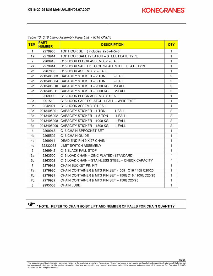
XN16-20-25 I&M MANUAL/EN/06.07.2007
55/65 This document and the information contained herein, is the exclusive property of Konecranes Plc and represents a non-public, confidential and proprietary trade secret that may not be reproduced, disclosed to third parties, altered or otherwise employed in any manner whatsoever without the express written consent of Konecranes Plc. Copyright © (2007) Konecranes Plc. All rights reserved.
Table 13. C16 Lifting Assembly Parts List - (C16 ONLY)
ITEM PART NUMBER
DESCRIPTION QTY
1 2279955 TOP HOOK SET ( includes 2+3+4+5+6 ) 1
1a 2279914 TOP HOOK SAFETY LATCH – STEEL PLATE TYPE 1
2 2269915 C16 HOOK BLOCK ASSEMBLY 2-FALL 1
2a 2279914 C16 HOOK SAFETY LATCH 2-FALL STEEL PLATE TYPE 1
2b 2267000 C16 HOOK ASSEMBLY 2-FALL 1
2d 2213405003 CAPACITY STICKER – 2 TON 2-FALL 2
2d 2213405004 CAPACITY STICKER – 3 TON 2-FALL 2
2d 2213405010 CAPACITY STICKER – 2000 KG 2-FALL 2
2d 2213405011 CAPACITY STICKER – 3000 KG 2-FALL 2
3 2269900 C16 HOOK BLOCK ASSEMBLY 1-FALL 1
3a 001513 C16 HOOK SAFETY LATCH 1-FALL – WIRE TYPE 1
3b 2242021 C16 HOOK ASSEMBLY 1-FALL 1
3d 2213405001 CAPACITY STICKER – 1 TON 1-FALL 2
3d 2213405002 CAPACITY STICKER – 1.5 TON 1-FALL 2
3d 2213405008 CAPACITY STICKER – 1000 KG 1-FALL 2
3d 2213405009 CAPACITY STICKER – 1500 KG 1-FALL 2
4 2269913 C16 CHAIN SPROCKET SET 1
4b 2265502 C16 CHAIN GUIDE 1
4c 2269914 DEAD END PIN 9 X 27 CHAIN 1
4d 52332038 LIMIT SWITCH ASSEMBLY 1
5 2269942 C16 SLACK FALL STOP 1
6a 2263500 C16 LOAD CHAIN – ZINC PLATED (STANDARD) *
6b 2263502 C16 LOAD CHAIN – STAINLESS STEEL – CHECK CAPACITY *
7 2279912 CHAIN BUCKET PIN KIT 1
7a 2279930 CHAIN CONTAINER & MTG PIN SET - 50ft C16 / 40ft C20/25 1
7b 2279931 CHAIN CONTAINER & MTG PIN SET – 150ft C16 / 100ft C20/25 1
7c 2279932 CHAIN CONTAINER & MTG PIN SET – 150ft C20/25 1
8 9995008 CHAIN LUBE 1
���� * NOTE: REFER TO CHAIN HOIST LIFT AND NUMBER OF FALLS FOR CHAIN QUANTITY

XN16-20-25 I&M MANUAL/EN/06.07.2007
56/65 This document and the information contained herein, is the exclusive property of Konecranes Plc and represents a non-public, confidential and proprietary trade secret that may not be reproduced, disclosed to third parties, altered or otherwise employed in any manner whatsoever without the express written consent of Konecranes Plc. Copyright © (2007) Konecranes Plc. All rights reserved.
7.4 Lifting Assembly – C20/25 Only
4d

XN16-20-25 I&M MANUAL/EN/06.07.2007
57/65 This document and the information contained herein, is the exclusive property of Konecranes Plc and represents a non-public, confidential and proprietary trade secret that may not be reproduced, disclosed to third parties, altered or otherwise employed in any manner whatsoever without the express written consent of Konecranes Plc. Copyright © (2007) Konecranes Plc. All rights reserved.
Table 14. C20 / C25 Lifting Assembly Parts List - (C20 / C25 ONLY)
ITEM PART NUMBER
DESCRIPTION QTY
1 2279955 TOP HOOK SET (includes 2+3+4+5+6) 1
1a 2279914 TOP HOOK SAFETY LATCH – STEEL PLATE TYPE 1
2 2279915 C20/25 HOOK BLOCK ASSEMBLY 2-FALL 1
2a 2279914 C20/25 HOOK SAFETY LATCH 2-FALL STEEL PLATE TYPE 1
2b 2277001 C20/25 HOOK ASSEMBLY 2-FALL 1
2d 2213406002 CAPACITY STICKER – 3 TON 2-FALL 2
2d 2213406005 CAPACITY STICKER – 4 TON 2-FALL 2
2d 2213406003 CAPACITY STICKER – 5 TON 2-FALL 2
2d 2213406009 CAPACITY STICKER – 3000 KG 2-FALL 2
2d 2213406013 CAPACITY STICKER – 4000 KG 2-FALL 2
2d 2213406010 CAPACITY STICKER – 5000 KG 2-FALL 2
3 2279900 C20/25 HOOK BLOCK ASSEMBLY 1-FALL 1
3a 2242017 C20/25 HOOK SAFETY LATCH 1-FALL – WIRE TYPE 1
3b 2277000 C20/25 HOOK ASSEMBLY 1-FALL 1
3d 2213405002 CAPACITY STICKER – 1.5 TON 1-FALL 2
3d 2213405003 CAPACITY STICKER – 2.0 TON 1-FALL 2
3d 2213405004 CAPACITY STICKER – 3.0 TON 1-FALL 2
3d 2213405009 CAPACITY STICKER – 1500 KG 1-FALL 2
3d 2213405010 CAPACITY STICKER – 2000 KG 1-FALL 2
3d 2213405007 CAPACITY STICKER – 3000 KG 1-FALL 2
4 2279911 C20/25 CHAIN SPROCKET SET 1
4b 2275502 C20/25 CHAIN GUIDE 1
4c 2279910 DEAD END PIN 11.3 X 31 CHAIN 1
4d 52332038 LIMIT SWITCH ASSEMBLY 1
5 2279942 C20/25 SLACK FALL STOP 1
6a 2273500 C20/25 LOAD CHAIN – ZINC PLATED (STANDARD) *
6b 2273502 C20/25 LOAD CHAIN – STAINLESS STEEL – CHECK CAPACITY *
7 2279912 CHAIN BUCKET PIN KIT 1
7a 2279930 CHAIN CONTAINER & MTG PIN SET – 50ft C16 / 40ft C20/25 1
7b 2279931 CHAIN CONTAINER & MTG PIN SET – 150ft C16 / 100ft C20/25 1
7c 2279932 CHAIN CONTAINER & MTG PIN SET – 150ft C20/25 1
8 9995008 CHAIN LUBE 1
���� * NOTE: REFER TO CHAIN HOIST LIFT AND NUMBER OF FALLS FOR CHAIN QUANTITY
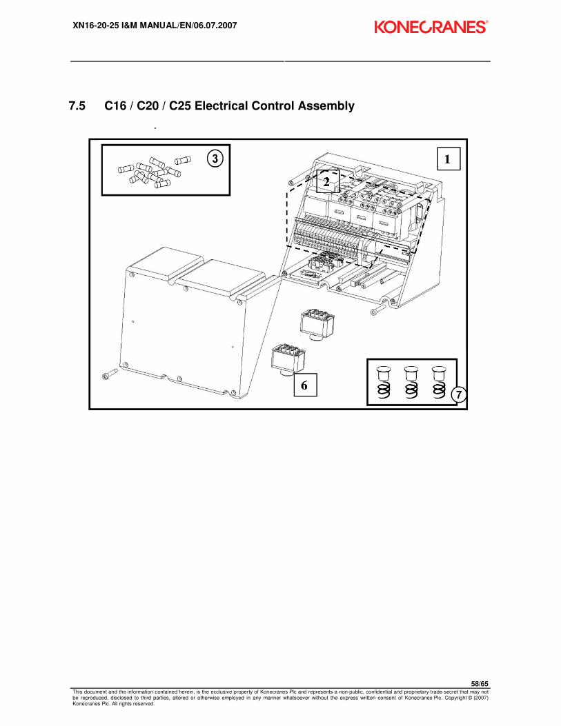
XN16-20-25 I&M MANUAL/EN/06.07.2007
58/65 This document and the information contained herein, is the exclusive property of Konecranes Plc and represents a non-public, confidential and proprietary trade secret that may not be reproduced, disclosed to third parties, altered or otherwise employed in any manner whatsoever without the express written consent of Konecranes Plc. Copyright © (2007) Konecranes Plc. All rights reserved.
7.5 C16 / C20 / C25 Electrical Control Assembly

XN16-20-25 I&M MANUAL/EN/06.07.2007
59/65 This document and the information contained herein, is the exclusive property of Konecranes Plc and represents a non-public, confidential and proprietary trade secret that may not be reproduced, disclosed to third parties, altered or otherwise employed in any manner whatsoever without the express written consent of Konecranes Plc. Copyright © (2007) Konecranes Plc. All rights reserved.
Table 15. C16/C20/C25 Electrical Control Assembly Parts List
ITEM PART NUMBER
DESCRIPTION QTY
1 2263015 CONTROL BOX (BASE + COVER) 1
2 2263006 CONTROL PANEL ASSEMBLY: 208/230/460V – 115V – 60HZ 1
2 2263007 CONTROL PANEL ASSEMBLY: 575V – 115V – 60HZ 1
2a 2309564003 CONTACTOR K10 - 208/230/460/575V – 115V CONT 1
2b 2309564006 CONTACTOR K21 or K22 - 208/230/460/575V – 115V CONT 1
2c 2309568004 CONTACTOR K25 - 208/230/460/575V – 115V CONT 1
2d 7983026 TRANSFORMER - 208/230/460V - 115V 1
2d 7983027 TRANSFORMER - 575V - 115V 1
2e 2243060 BRAKE RECTIFIER 4 – WIRES 208 - 575VAC 1
2e 2243061 BRAKE RECTIFIER 5 – WIRES 208 - 460VAC (RECONNECT) 1
3 2249979 1.25 AMP FUSES – SET OF 10 1
4 2249947 POWER CABLE GLAND – NOT SHOWN 1
5 2219814 COVER PLATE – USED WHEN PLUG IS REMOVED – NOT SHOWN 1
6 2249946 PLUG FOR TROLLEY CIRCUIT 1
6 2249982 POWER PLUG – OPTIONAL 1
6 2249945 PLUG FOR PENDANT 1
7a 2269010 C16 SPRING & WASHER ASSEMBLY – 1 FALL 2
7a 2269010 C16 SPRING & WASHER ASSEMBLY – 2 FALL 3
7b 2279010 C20/25 SPRING & WASHER ASSEMBLY – 1 FALL 2
7b 2279010 C20/25 SPRING & WASHER ASSEMBLY – 2 FALL 3
- 2213445001 ELECTRICAL WIRING INFORMATION STICKER 1
- 2213445002 ELECTRICAL HAZARD WARNING STICKER 1
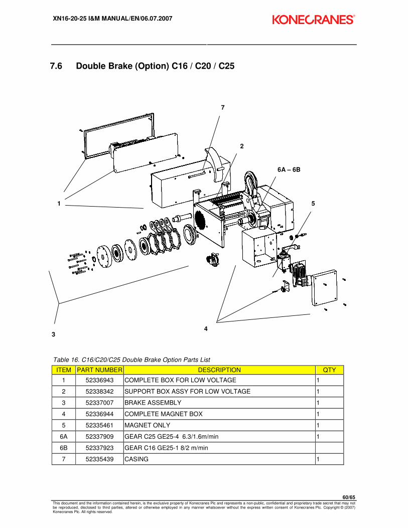
XN16-20-25 I&M MANUAL/EN/06.07.2007
60/65 This document and the information contained herein, is the exclusive property of Konecranes Plc and represents a non-public, confidential and proprietary trade secret that may not be reproduced, disclosed to third parties, altered or otherwise employed in any manner whatsoever without the express written consent of Konecranes Plc. Copyright © (2007) Konecranes Plc. All rights reserved.
7.6 Double Brake (Option) C16 / C20 / C25
Table 16. C16/C20/C25 Double Brake Option Parts List
ITEM PART NUMBER DESCRIPTION QTY
1 52336943 COMPLETE BOX FOR LOW VOLTAGE 1
2 52338342 SUPPORT BOX ASSY FOR LOW VOLTAGE 1
3 52337007 BRAKE ASSEMBLY 1
4 52336944 COMPLETE MAGNET BOX 1
5 52335461 MAGNET ONLY 1
6A 52337909 GEAR C25 GE25-4 6.3/1.6m/min 1
6B 52337923 GEAR C16 GE25-1 8/2 m/min
7 52335439 CASING 1
1
2
3 4
5
6A – 6B
7

XN16-20-25 I&M MANUAL/EN/06.07.2007
61/65 This document and the information contained herein, is the exclusive property of Konecranes Plc and represents a non-public, confidential and proprietary trade secret that may not be reproduced, disclosed to third parties, altered or otherwise employed in any manner whatsoever without the express written consent of Konecranes Plc. Copyright © (2007) Konecranes Plc. All rights reserved.
7.7 Push Button Assembly – Horizontal Pairs of Buttons
Table 17. Push Button Assembly (Horizontal Pairs of Buttons) Parts List
ITEM PART
NUMBER DESCRIPTION QTY
- 2309765010 P/B ASSEMBLY 10 FT, E-STOP, TWO SPEED HOIST 1
- 2309765015 P/B ASSEMBLY 15 FT, E-STOP, TWO SPEED HOIST 1
- 2309765020 P/B ASSEMBLY 20 FT, E-STOP, TWO SPEED HOIST 1
- 2309767010 P/B ASSEMBLY 10 FT, E-STOP, TWO SPEED HOIST, TWO SPEED TROLLEY 1
- 2309767015 P/B ASSEMBLY 15 FT, E-STOP, TWO SPEED HOIST, TWO SPEED TROLLEY 1
- 2309767020 P/B ASSEMBLY 20 FT, E-STOP, TWO SPEED HOIST, TWO SPEED TROLLEY 1
2 2218000 UPPER SUSPENSION KIT 1
3 7285036 P/B ASSEMBLY - PLUG KIT 1
5 52292266 PUSH BUTTON ELECTRICAL CABLE 16 GAUGE / 12 CONDUCTOR RPC 1
6 52301832 P/B ENCLOSURE ASSEMBLY: E-STOP, TH 1
6 2213466004 P/B ENCLOSURE ASSEMBLY: E-STOP, TH, TT 1
6 2309414004 XN OPERATOR’S WARNING TAG - ENGLISH 1

XN16-20-25 I&M MANUAL/EN/06.07.2007
62/65 This document and the information contained herein, is the exclusive property of Konecranes Plc and represents a non-public, confidential and proprietary trade secret that may not be reproduced, disclosed to third parties, altered or otherwise employed in any manner whatsoever without the express written consent of Konecranes Plc. Copyright © (2007) Konecranes Plc. All rights reserved.
7.8 Push Button Assembly – Horizontal Pairs of Buttons
Table 18. Push Button Assembly – Horizontal Pairs of Buttons Parts List
ITEM PART NUMBER DESCRIPTION QTY
1 52301832 PISTOL GRIP P/B CONTROL ASSEMBLY – TWO SPEED 1
2 2213466004 P/B CONTROL ASSEMBLY – TWO SPEED – 5 BUTTON 1
3 2213466005 P/B CONTROL ASSEMBLY – TWO SPEED – 7 BUTTON 1
2 1 3

XN16-20-25 I&M MANUAL/EN/06.07.2007
63/65 This document and the information contained herein, is the exclusive property of Konecranes Plc and represents a non-public, confidential and proprietary trade secret that may not be reproduced, disclosed to third parties, altered or otherwise employed in any manner whatsoever without the express written consent of Konecranes Plc. Copyright © (2007) Konecranes Plc. All rights reserved.
7.9 Push Button Assembly – Vertical Pairs of Buttons (Option)
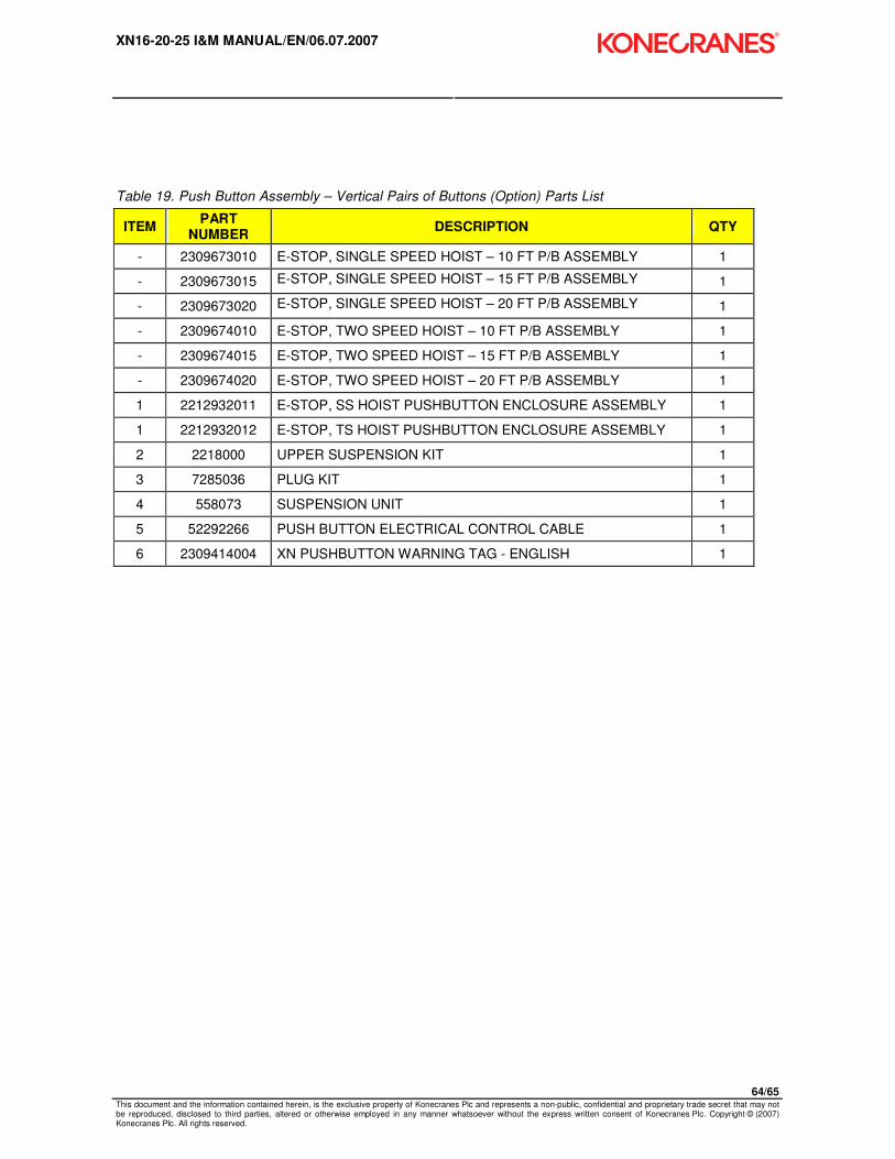
XN16-20-25 I&M MANUAL/EN/06.07.2007
64/65 This document and the information contained herein, is the exclusive property of Konecranes Plc and represents a non-public, confidential and proprietary trade secret that may not be reproduced, disclosed to third parties, altered or otherwise employed in any manner whatsoever without the express written consent of Konecranes Plc. Copyright © (2007) Konecranes Plc. All rights reserved.
Table 19. Push Button Assembly – Vertical Pairs of Buttons (Option) Parts List
ITEM PART
NUMBER DESCRIPTION QTY
- 2309673010 E-STOP, SINGLE SPEED HOIST – 10 FT P/B ASSEMBLY 1
- 2309673015 E-STOP, SINGLE SPEED HOIST – 15 FT P/B ASSEMBLY 1
- 2309673020 E-STOP, SINGLE SPEED HOIST – 20 FT P/B ASSEMBLY 1
- 2309674010 E-STOP, TWO SPEED HOIST – 10 FT P/B ASSEMBLY 1
- 2309674015 E-STOP, TWO SPEED HOIST – 15 FT P/B ASSEMBLY 1
- 2309674020 E-STOP, TWO SPEED HOIST – 20 FT P/B ASSEMBLY 1
1 2212932011 E-STOP, SS HOIST PUSHBUTTON ENCLOSURE ASSEMBLY 1
1 2212932012 E-STOP, TS HOIST PUSHBUTTON ENCLOSURE ASSEMBLY 1
2 2218000 UPPER SUSPENSION KIT 1
3 7285036 PLUG KIT 1
4 558073 SUSPENSION UNIT 1
5 52292266 PUSH BUTTON ELECTRICAL CONTROL CABLE 1
6 2309414004 XN PUSHBUTTON WARNING TAG - ENGLISH 1
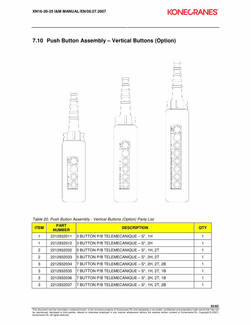
XN16-20-25 I&M MANUAL/EN/06.07.2007
65/65 This document and the information contained herein, is the exclusive property of Konecranes Plc and represents a non-public, confidential and proprietary trade secret that may not be reproduced, disclosed to third parties, altered or otherwise employed in any manner whatsoever without the express written consent of Konecranes Plc. Copyright © (2007) Konecranes Plc. All rights reserved.
7.10 Push Button Assembly – Vertical Buttons (Option)
Table 20. Push Button Assembly - Vertical Buttons (Option) Parts List
ITEM PART
NUMBER DESCRIPTION QTY
1 2212932011 3 BUTTON P/B TELEMECANIQUE – S*, 1H 1
1 2212932012 3 BUTTON P/B TELEMECANIQUE – S*, 2H 1
2 2212932032 5 BUTTON P/B TELEMECANIQUE – S*, 1H, 2T 1
2 2212932033 5 BUTTON P/B TELEMECANIQUE – S*, 2H, 2T 1
3 2212932034 7 BUTTON P/B TELEMECANIQUE – S*, 2H, 2T, 2B 1
3 2212932035 7 BUTTON P/B TELEMECANIQUE – S*, 1H, 2T, 1B 1
3 2212932036 7 BUTTON P/B TELEMECANIQUE – S*, 2H, 2T, 1B 1
3 2212932037 7 BUTTON P/B TELEMECANIQUE – S*, 1H, 2T, 2B 1
Top Related