


Languages
Pages
Legal


INROADS SURVEY V8i SELECT SERIES 1 (SS1) (V08.11.07.229)
SELECT SERIES 1 REFRESH (SS1R) (V08.11.07.246) SELECT SERIES 2 (SS2) (V08.11.07.428)
ADDENDUM WHY USE AN ADDENDUM:
This addendum is meant to accompany the Zen Guide to InRoads Survey V8i Essentials
Workbook. Bentley has released some new versions of the software that include minor changes to the way the InRoads V8i software interface looks and functions. These new releases, SS1, SS1R and SS2 are still considered to be under the V8i umbrella and therefore we here at Zen felt it was best to just issue an Addendum so not to complicate the issue of determining which training workbook you need. When you upgrade your software to InRoads V8i SS1, SS1R or SS2; simply purchase the V8i Workbook and we will include the addendum if you are using either SS1, SS1R or SS2!
HOW TO USE THIS ADDENDUM:
The way this addendum was written was not to take the place of the Zen Guide to
InRoads Survey V8i Essentials Workbook, but instead to supplement it. The addendum is broken down by chapters and pages that correspond to the same areas of the V8i Workbook, and only contains areas that have changed. The steps and screen captures are virtually identical as the areas in the V8i book but with subtle differences like rewritten directions or dialog boxes as they appear in the SS1/SS1R/SS2 version of the software. To help you identify the text portions that have changed, the addendum had underlined the changes.
Only a couple sections of the V8i Workbook have changed significantly enough to warrant a completely rewritten section in the addendum. To help easily identify those areas, a small paragraph has been inserted into the actual V8i Workbook under the section heading. NOTE: You may notice on occasion that the dialog box you are looking at on the computer may contain an additional toggle or data field compared to what’s in the V8i
Workbook. It may be the case that due to the purposes of the training exercise or the overall workflow of the workbook those areas of the dialog box were not pertinent and therefore were not discussed in the workbook. If you wish to learn about these added areas (or any other areas not discussed throughout the workbook), feel free to click the help button on that dialog box to gain more information.
It may be helpful to quickly run through the addendum while placing tabs in the V8i workbook on the corresponding pages to help remind yourself later
during your training to refer to the addendum when you get to those pages.
CHAPTER
Survey V8i SS1, SS1R and SS2 Addendum 1
1.1 Introduction
Page 9- Software InformationThis guide was written while running InRoads V8i Select Series 2, Version 08.11.07.428 on MicroStation V8i Select Series 2, Version 08.11.07.443.
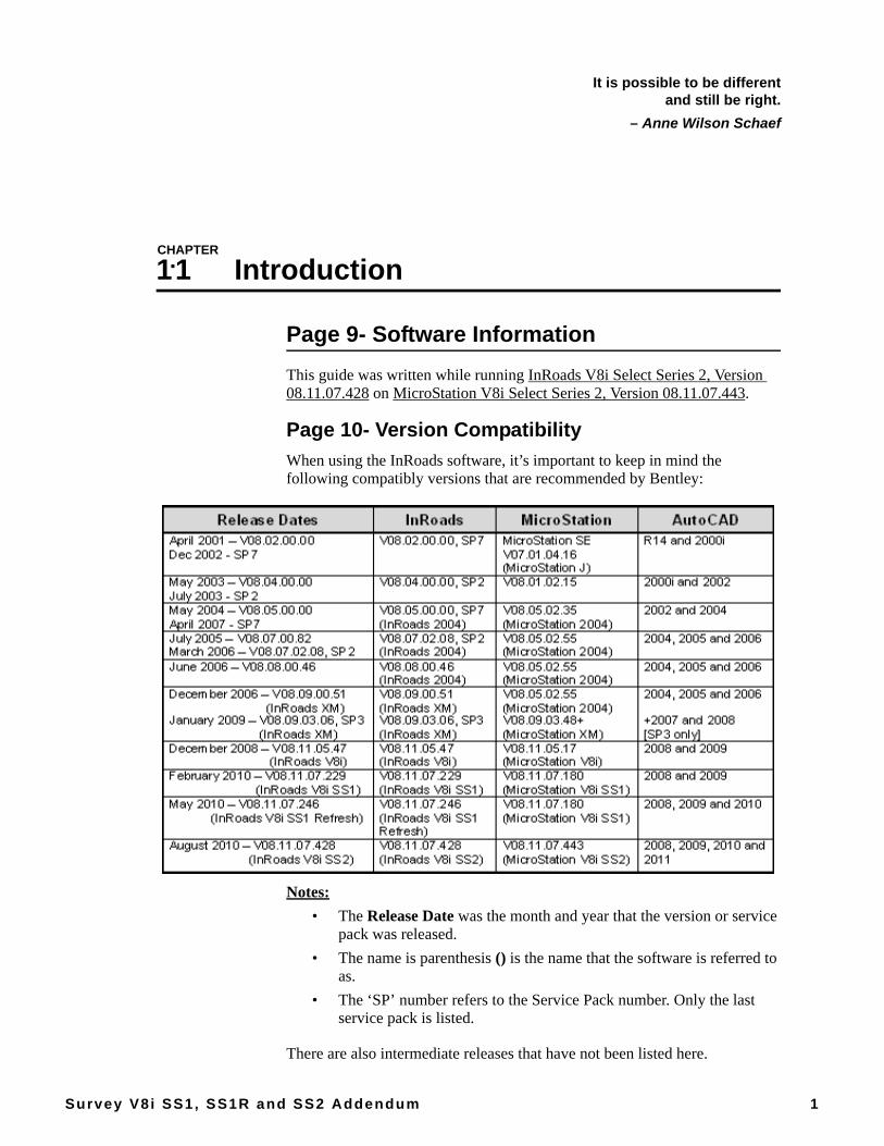
Page 10- Version CompatibilityWhen using the InRoads software, it’s important to keep in mind the following compatibly versions that are recommended by Bentley:
Notes:• The Release Date was the month and year that the version or service
pack was released.• The name is parenthesis () is the name that the software is referred to
as.• The ‘SP’ number refers to the Service Pack number. Only the last
service pack is listed.
There are also intermediate releases that have not been listed here.
It is possible to be differentand still be right.
– Anne Wilson Schaef
CHAPTER
Survey V8i SS1, SS1R and SS2 Addendum 2
1.2 Orientation to InRoads Survey
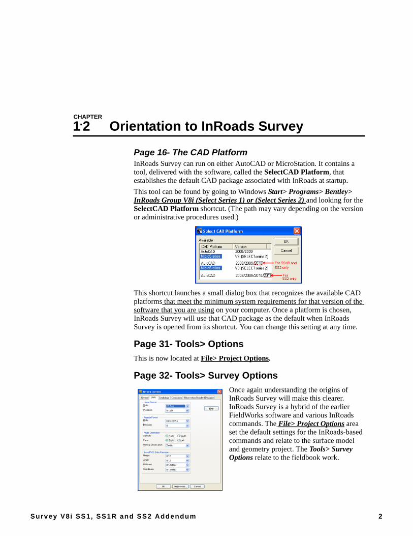
Page 16- The CAD PlatformInRoads Survey can run on either AutoCAD or MicroStation. It contains a tool, delivered with the software, called the SelectCAD Platform, that establishes the default CAD package associated with InRoads at startup.This tool can be found by going to Windows Start> Programs> Bentley> InRoads Group V8i (Select Series 1) or (Select Series 2) and looking for the SelectCAD Platform shortcut. (The path may vary depending on the version or administrative procedures used.)
This shortcut launches a small dialog box that recognizes the available CAD platforms that meet the minimum system requirements for that version of the software that you are using on your computer. Once a platform is chosen, InRoads Survey will use that CAD package as the default when InRoads Survey is opened from its shortcut. You can change this setting at any time.
Page 31- Tools> OptionsThis is now located at File> Project Options.
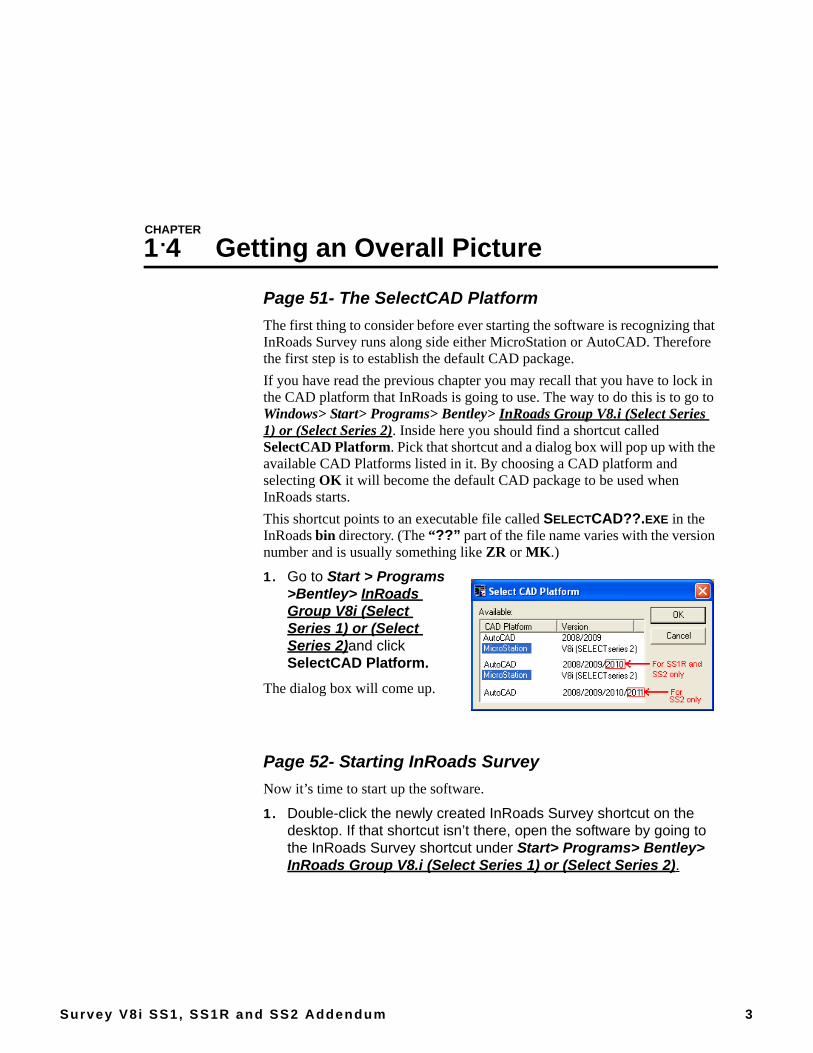
Page 32- Tools> Survey OptionsOnce again understanding the origins of InRoads Survey will make this clearer. InRoads Survey is a hybrid of the earlier FieldWorks software and various InRoads commands. The File> Project Options area set the default settings for the InRoads-based commands and relate to the surface model and geometry project. The Tools> Survey Options relate to the fieldbook work.
CHAPTER
Survey V8i SS1, SS1R and SS2 Addendum 3
1.4 Getting an Overall Picture
Page 51- The SelectCAD PlatformThe first thing to consider before ever starting the software is recognizing that InRoads Survey runs along side either MicroStation or AutoCAD. Therefore the first step is to establish the default CAD package.If you have read the previous chapter you may recall that you have to lock in the CAD platform that InRoads is going to use. The way to do this is to go to Windows> Start> Programs> Bentley> InRoads Group V8.i (Select Series 1) or (Select Series 2). Inside here you should find a shortcut called SelectCAD Platform. Pick that shortcut and a dialog box will pop up with the available CAD Platforms listed in it. By choosing a CAD platform and selecting OK it will become the default CAD package to be used when InRoads starts.This shortcut points to an executable file called SELECTCAD??.EXE in the InRoads bin directory. (The “??” part of the file name varies with the version number and is usually something like ZR or MK.)
1. Go to Start > Programs >Bentley> InRoads Group V8i (Select Series 1) or (Select Series 2)and click SelectCAD Platform.
The dialog box will come up.
Page 52- Starting InRoads SurveyNow it’s time to start up the software.
1. Double-click the newly created InRoads Survey shortcut on the desktop. If that shortcut isn’t there, open the software by going to the InRoads Survey shortcut under Start> Programs> Bentley> InRoads Group V8.i (Select Series 1) or (Select Series 2).
InRoads Survey V8i SS1, SS1R and SS2 Addendum
4 The Zen Guide to InRoads
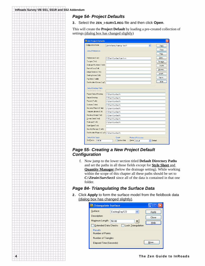
Page 54- Project Defaults3. Select the ZEN_I-SURV1.REG file and then click Open.
This will create the Project Default by loading a pre-created collection of settings (dialog box has changed slightly)
Page 55- Creating a New Project Default Configuration
f. Now jump to the lower section titled Default Directory Paths and set the paths in all those fields except for Style Sheet and Quantity Manager (below the drainage setting). While working within the scope of this chapter all these paths should be set to C:\Ztrain\SurvSect1 since all of the data is contained in that one folder.
Page 84- Triangulating the Surface Data2. Click Apply to form the surface model from the fieldbook data
(dialog box has changed slightly).
CHAPTER
Survey V8i SS1, SS1R and SS2 Addendum 5
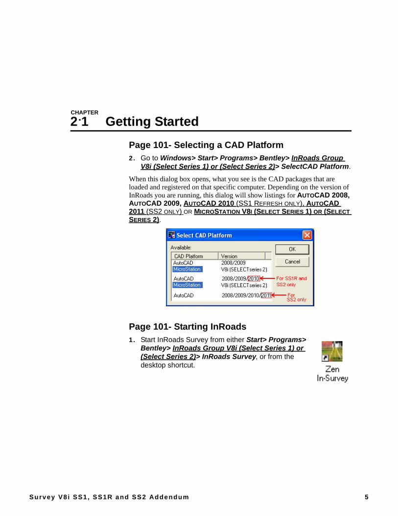
2.1 Getting StartedPage 101- Selecting a CAD Platform2. Go to Windows> Start> Programs> Bentley> InRoads Group
V8i (Select Series 1) or (Select Series 2)> SelectCAD Platform.
When this dialog box opens, what you see is the CAD packages that are loaded and registered on that specific computer. Depending on the version of InRoads you are running, this dialog will show listings for AUTOCAD 2008, AUTOCAD 2009, AUTOCAD 2010 (SS1 REFRESH ONLY), AUTOCAD 2011 (SS2 ONLY) OR MICROSTATION V8I (SELECT SERIES 1) OR (SELECT SERIES 2).
Page 101- Starting InRoads1. Start InRoads Survey from either Start> Programs>
Bentley> InRoads Group V8i (Select Series 1) or (Select Series 2)> InRoads Survey, or from the desktop shortcut.
InRoads Survey V8i SS1, SS1R and SS2 Addendum
6 The Zen Guide to InRoads
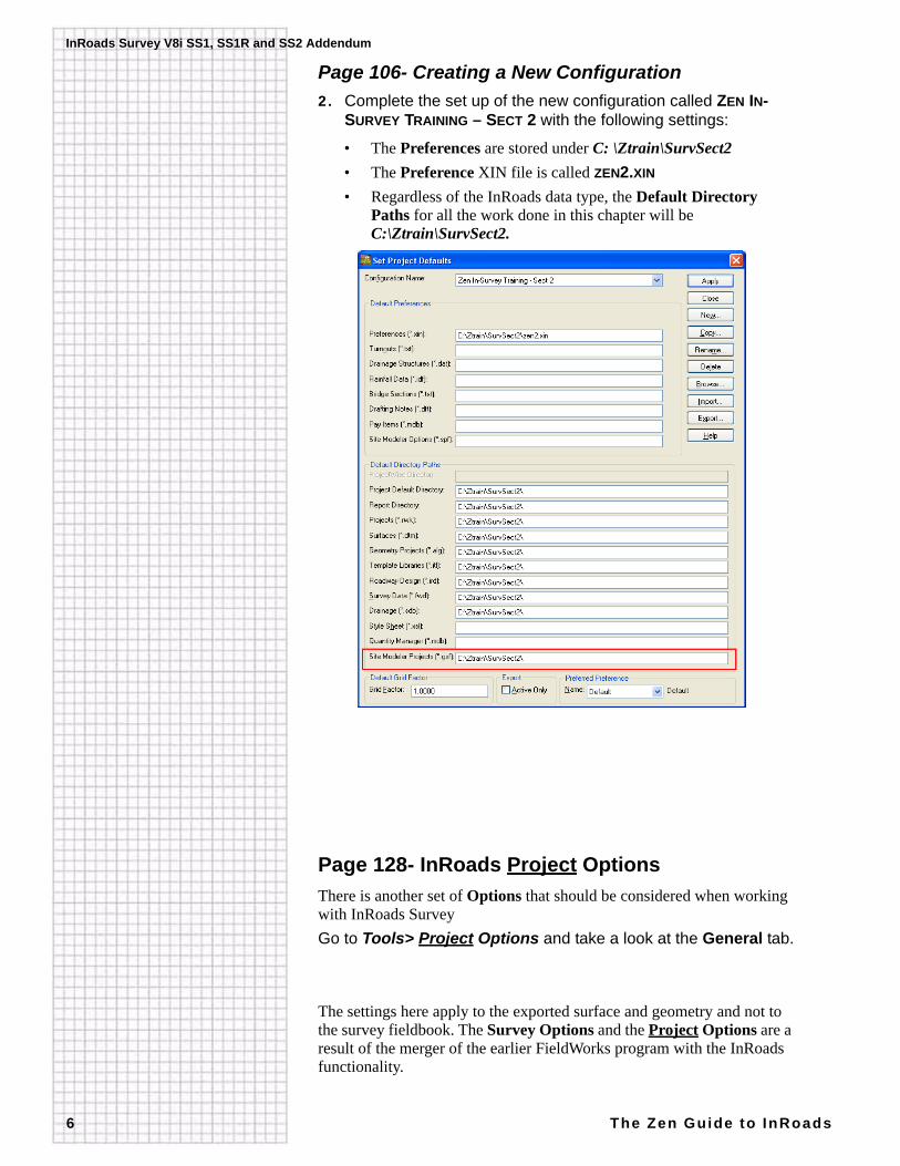
Page 106- Creating a New Configuration2. Complete the set up of the new configuration called ZEN IN-
SURVEY TRAINING – SECT 2 with the following settings:
• The Preferences are stored under C: \Ztrain\SurvSect2• The Preference XIN file is called ZEN2.XIN
• Regardless of the InRoads data type, the Default Directory Paths for all the work done in this chapter will be C:\Ztrain\SurvSect2.
Page 128- InRoads Project OptionsThere is another set of Options that should be considered when working with InRoads SurveyGo to Tools> Project Options and take a look at the General tab.
The settings here apply to the exported surface and geometry and not to the survey fieldbook. The Survey Options and the Project Options are a result of the merger of the earlier FieldWorks program with the InRoads functionality.

2.1 Getting Started
Survey V8i SS1, SS1R and SS2 Addendum 7
Page 130- Chapter Challenge
Additional Exercises1. Browse through the Survey Options as well as the other
Project Options using the Help to clarify anything not understood.
Page 131- Quiz Questions25.What file are the Project Options stored in?
Page 132- Chapter As-Builts
Quick ReviewBoth the Survey Options and InRoads Project Options were touched on

CHAPTER
Survey V8i SS1, SS1R and SS2 Addendum 8
2.2 The Style Manager
Page 134- Hands On—The Feature Table
Starting InRoads Survey2. Start InRoads Survey from either Start> Programs>
Bentley> InRoads Group V8i (Select Series 1) or (Select Series 2)> InRoads Survey, or from the desktop shortcut.
2.3 The Fieldbook
Page 170- Hands On—The Fieldbook
Starting InRoads Survey2. Start InRoads Survey from either Start> Programs>
Bentley> InRoads Group V8i (Select Series 1) or (Select SEries 2)> InRoads Survey, or from the desktop shortcut.
CHAPTER
Survey V8i SS1, SS1R and SS2 Addendum 9
2.4 Exporting the Fieldbook
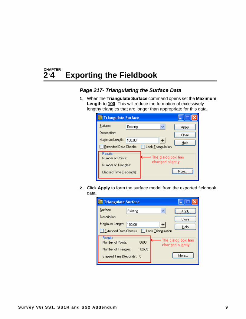
Page 217- Triangulating the Surface Data1. When the Triangulate Surface command opens set the Maximum
Length to 100. This will reduce the formation of excessively lengthy triangles that are longer than appropriate for this data.
2. Click Apply to form the surface model from the exported fieldbook data.
InRoads Survey V8i SS1, SS1R and SS2 Addendum
10 The Zen Guide to InRoads
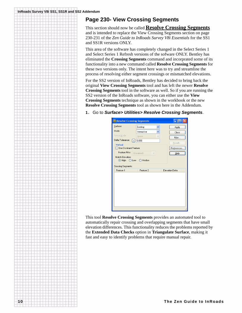
Page 230- View Crossing SegmentsThis section should now be called Resolve Crossing Segments and is intended to replace the View Crossing Segments section on page 230-231 of the Zen Guide to InRoads Survey V8i Essentials for the SS1 and SS1R versions ONLY.This area of the software has completely changed in the Select Series 1 and Select Series 1 Refresh versions of the sofware ONLY. Bentley has eliminated the Crossing Segments command and incorprated some of its functionality into a new command called Resolve Crossing Segments for these two versions only. The intent here was to try and streamline the process of resolving either segment crossings or mismatched elevations.For the SS2 version of InRoads, Bentley has decided to bring back the original View Crossing Segments tool and has left the newer Resolve Crossing Segments tool in the software as well. So if you are running the SS2 version of the InRoads software, you can either use the View Crossing Segments technique as shown in the workbook or the new Resolve Crossing Segments tool as shown here in the Addendum.
1. Go to Surface> Utilities> Resolve Crossing Segments.
This tool Resolve Crossing Segments provides an automated tool to automatically repair crossing and overlapping segments that have small elevation differences. This functionality reduces the problems reported by the Extended Data Checks option in Triangulate Surface, making it fast and easy to identify problems that require manual repair.
2.4 Exporting the Fieldbook
Survey V8i SS1, SS1R and SS2 Addendum 11
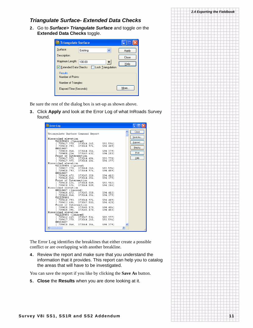
Triangulate Surface- Extended Data Checks2. Go to Surface> Triangulate Surface and toggle on the
Extended Data Checks toggle.
Be sure the rest of the dialog box is set-up as shown above.
3. Click Apply and look at the Error Log of what InRoads Survey found.
The Error Log identifies the breaklines that either create a possible conflict or are overlapping with another breakline.
4. Review the report and make sure that you understand the information that it provides. This report can help you to catalog the areas that will have to be investigated.
You can save the report if you like by clicking the Save As button.
5. Close the Results when you are done looking at it.
InRoads Survey V8i SS1, SS1R and SS2 Addendum
12 The Zen Guide to InRoads
Resolve Crossing Segments RevisitedThis command is a very versitile command and allows the user much flexibility in how they wish to resolve each error in the surface. The user may find that certain errors could be resolved automatically by the software while others may need to be investigated a little deeper and thus an interactive approach may be more suitable.Let’s take a closer look at the dialog box and each of its sections. This will help us understand the inherent flexibility with this tool.
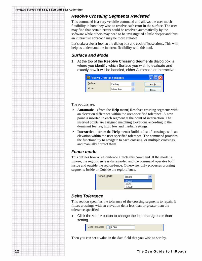
Surface and Mode1. At the top of the Resolve Crossing Segments dialog box is
where you identifiy which Surface you wish to evaluate and exactly how it will be handled, either Automatic or Interactive.
The options are:Automatic—(from the Help menu) Resolves crossing segments with an elevation difference within the user-specified tolerance. A new point is inserted in each segment at the point of intersection. The inserted points are assigned matching elevations according to the dominant feature, high, low and median settings.Interactive—(from the Help menu) Builds a list of crossings with an elevation within the user-specified tolerance. The command provides the functionality to navigate to each crossing, or multiple crossings, and manually correct them.
Fence modeThis defines how a region/fence affects this command. If the mode is Ignore, the region/fence is disregarded and the command operates both inside and outside the region/fence. Otherwise, only processes crossing segments Inside or Outside the region/fence.
Delta ToleranceThis section specifies the tolerance of the crossing segments to repair. It filters crossings with an elevation delta less than or greater than the tolerance specified.
1. Click the < or > button to change the less than/greater than setting.
Then you can set a value in the data field that you wish to sort by.
2.4 Exporting the Fieldbook
Survey V8i SS1, SS1R and SS2 Addendum 13
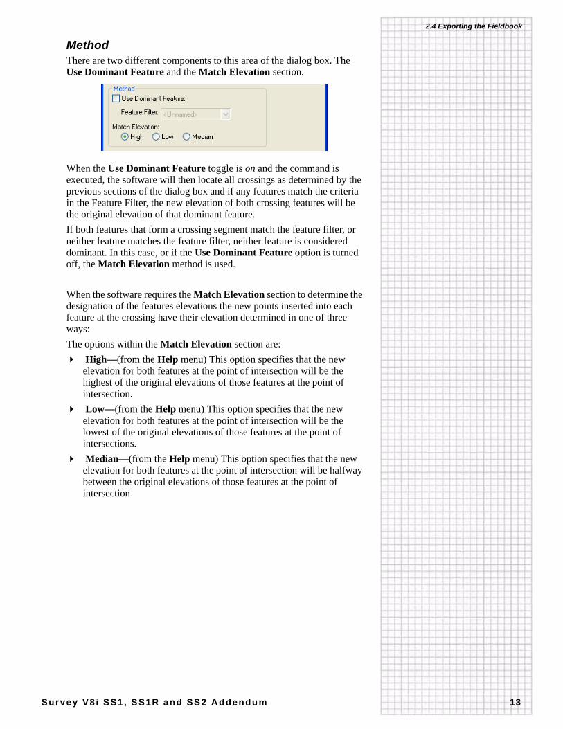
MethodThere are two different components to this area of the dialog box. The Use Dominant Feature and the Match Elevation section.
When the Use Dominant Feature toggle is on and the command is executed, the software will then locate all crossings as determined by the previous sections of the dialog box and if any features match the criteria in the Feature Filter, the new elevation of both crossing features will be the original elevation of that dominant feature.If both features that form a crossing segment match the feature filter, or neither feature matches the feature filter, neither feature is considered dominant. In this case, or if the Use Dominant Feature option is turned off, the Match Elevation method is used.
When the software requires the Match Elevation section to determine the designation of the features elevations the new points inserted into each feature at the crossing have their elevation determined in one of three ways:The options within the Match Elevation section are:
High—(from the Help menu) This option specifies that the new elevation for both features at the point of intersection will be the highest of the original elevations of those features at the point of intersection. Low—(from the Help menu) This option specifies that the new elevation for both features at the point of intersection will be the lowest of the original elevations of those features at the point of intersections. Median—(from the Help menu) This option specifies that the new elevation for both features at the point of intersection will be halfway between the original elevations of those features at the point of intersection
InRoads Survey V8i SS1, SS1R and SS2 Addendum
14 The Zen Guide to InRoads
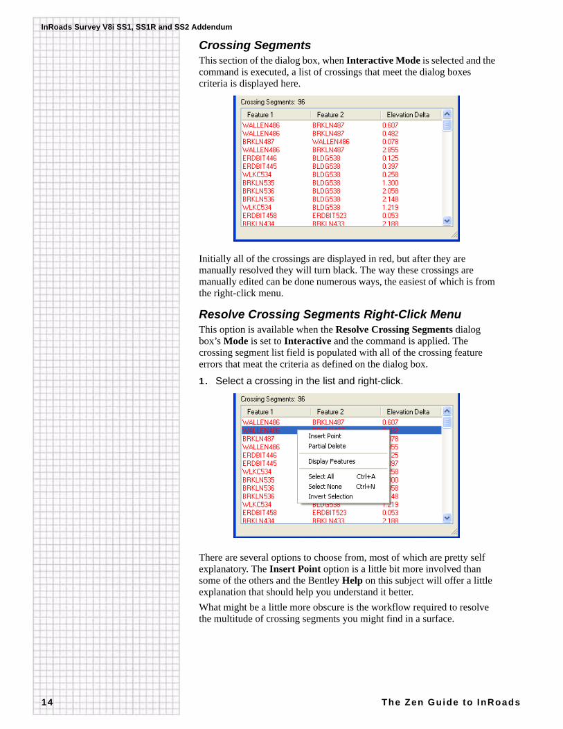
Crossing SegmentsThis section of the dialog box, when Interactive Mode is selected and the command is executed, a list of crossings that meet the dialog boxes criteria is displayed here.
Initially all of the crossings are displayed in red, but after they are manually resolved they will turn black. The way these crossings are manually edited can be done numerous ways, the easiest of which is from the right-click menu.
Resolve Crossing Segments Right-Click MenuThis option is available when the Resolve Crossing Segments dialog box’s Mode is set to Interactive and the command is applied. The crossing segment list field is populated with all of the crossing feature errors that meat the criteria as defined on the dialog box.
1. Select a crossing in the list and right-click.
There are several options to choose from, most of which are pretty self explanatory. The Insert Point option is a little bit more involved than some of the others and the Bentley Help on this subject will offer a little explanation that should help you understand it better.What might be a little more obscure is the workflow required to resolve the multitude of crossing segments you might find in a surface.
2.4 Exporting the Fieldbook
Survey V8i SS1, SS1R and SS2 Addendum 15
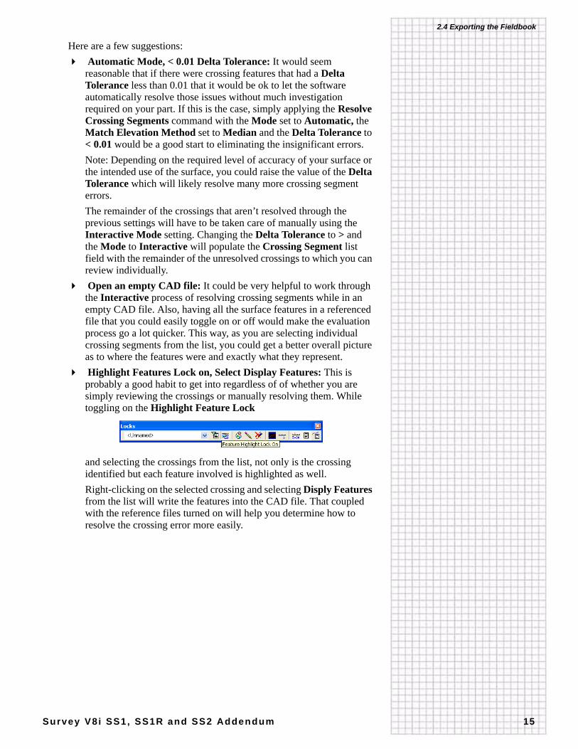
Here are a few suggestions: Automatic Mode, < 0.01 Delta Tolerance: It would seem reasonable that if there were crossing features that had a Delta Tolerance less than 0.01 that it would be ok to let the software automatically resolve those issues without much investigation required on your part. If this is the case, simply applying the Resolve Crossing Segments command with the Mode set to Automatic, the Match Elevation Method set to Median and the Delta Tolerance to < 0.01 would be a good start to eliminating the insignificant errors.Note: Depending on the required level of accuracy of your surface or the intended use of the surface, you could raise the value of the Delta Tolerance which will likely resolve many more crossing segment errors.The remainder of the crossings that aren’t resolved through the previous settings will have to be taken care of manually using the Interactive Mode setting. Changing the Delta Tolerance to > and the Mode to Interactive will populate the Crossing Segment list field with the remainder of the unresolved crossings to which you can review individually. Open an empty CAD file: It could be very helpful to work through the Interactive process of resolving crossing segments while in an empty CAD file. Also, having all the surface features in a referenced file that you could easily toggle on or off would make the evaluation process go a lot quicker. This way, as you are selecting individual crossing segments from the list, you could get a better overall picture as to where the features were and exactly what they represent. Highlight Features Lock on, Select Display Features: This is probably a good habit to get into regardless of of whether you are simply reviewing the crossings or manually resolving them. While toggling on the Highlight Feature Lock
and selecting the crossings from the list, not only is the crossing identified but each feature involved is highlighted as well.Right-clicking on the selected crossing and selecting Disply Features from the list will write the features into the CAD file. That coupled with the reference files turned on will help you determine how to resolve the crossing error more easily.
InRoads Survey V8i SS1, SS1R and SS2 Addendum
16 The Zen Guide to InRoads
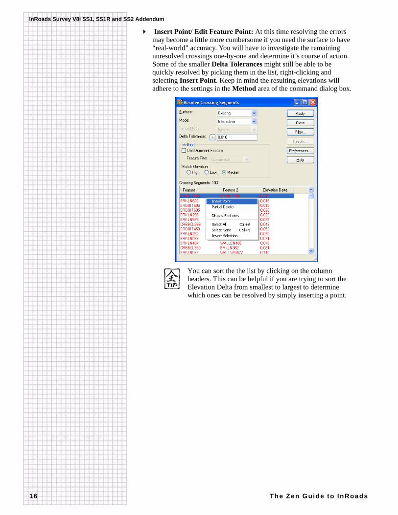
Insert Point/ Edit Feature Point: At this time resolving the errors may become a little more cumbersome if you need the surface to have “real-world” accuracy. You will have to investigate the remaining unresolved crossings one-by-one and determine it’s course of action. Some of the smaller Delta Tolerances might still be able to be quickly resolved by picking them in the list, right-clicking and selecting Insert Point. Keep in mind the resulting elevations will adhere to the settings in the Method area of the command dialog box.
You can sort the the list by clicking on the column headers. This can be helpful if you are trying to sort the Elevation Delta from smallest to largest to determine which ones can be resolved by simply inserting a point.
2.4 Exporting the Fieldbook
Survey V8i SS1, SS1R and SS2 Addendum 17
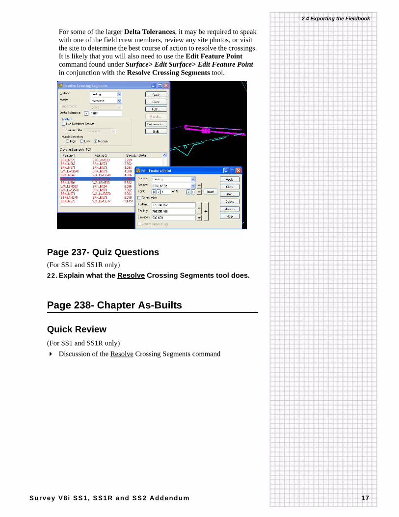
For some of the larger Delta Tolerances, it may be required to speak with one of the field crew members, review any site photos, or visit the site to determine the best course of action to resolve the crossings. It is likely that you will also need to use the Edit Feature Point command found under Surface> Edit Surface> Edit Feature Point in conjunction with the Resolve Crossing Segments tool.
Page 237- Quiz Questions(For SS1 and SS1R only)22.Explain what the Resolve Crossing Segments tool does.
Page 238- Chapter As-Builts
Quick Review(For SS1 and SS1R only)
Discussion of the Resolve Crossing Segments command
APPENDIX
Survey V8i SS1, SS1R and SS2 Addendum 18
A: Exterior Boundary Creation
Page 242- Starting InRoads Survey2. Start InRoads Survey from either Start> Programs>
Bentley> InRoads Group V8i (Select Series 1) or (Select Series 2)> InRoads Survey, or from the desktop shortcut.
B: The InRoads Locks
Page 270- IgnoringThese tags cannot be viewed by the average user and really aren’t meant to be, nor is it necessary, since InRoads keeps track of them.On the General tab under File> Project Options is a setting to Omit Automatic Graphics Refresh.
Top Related