


![Inline filter RE 51401/08.08 [inch] filtri in linea/40 FLEN, 40... · Inline filter 1/10 Types 40 FLEN 0160 to 1000; ... BV, DNV, DRIRE, UDT, etc.) is available on request. ... 2)](https://static.fdocuments.in/doc/165x107/5b16623a7f8b9a4f6d8ba71e/inline-filter-re-514010808-inch-filtri-in-linea40-flen-40-inline-filter.jpg)


Languages
Pages
Legal

1/16Inline filter
Types 40 FLEN 0160 to 1000; 40 FLE 0045, 0055, 0120 to 0270
Nominal sizes according to DIN 24550: 0160 to 1000Nominal sizes according to BRFS: 0045, 0055, 0120 to 270Nominal pressure 40 barConnections up to SAE 4”Operating temperature –10 ℃ to +100 ℃
RE 51401/09.10Replaces: 01.09
Table of contents Application– Filtration of pressure fluids and lubricants.– Filtration of fluids and gases.– Direct installation into pipe work.– Direct wear protection of downstream components and systems.– Offline filtration at high filter service lives.
Contents PageApplication, Features 1Design, Filter element, Accessories, Characteristic curvesQuality and standardization 2Ordering code 3Preferred types 4Ordering details:Electronic switching element for clogging indicator 5Plug-in connectors according to IEC 60947-5-2 5Symbols 6Technical data 7Characteristic curves 8 … 11Dimensions 12, 13Spare parts 14, 15Installation, commissioning and maintenance 16
Features– Filters for inline installation– Particularly suited for off-line filtration– Extremely large filter area– Flow optimised design due to 3D computer-supported design– Low pressure drop– Special highly efficient filter media
2/16 Bosch Rexroth AG Hydraulics 40 FLEN 0160 - 1000; 40 FLE 0045, 0055, 0120 - 0270 RE 51401/09.10
Filter elementPleated design with optimised pleat density and various filter media.The filter element is the most important component of the sys-tem “FILTER” in view of prolonged life and wear protection of the system.The most important criteria for selection are the required de-gree of cleanliness of the operating medium, the initial pres-sure differential and the contamination retention capacity.
For further detailed information please refer to our “Filter Ele-ments” brochure.
AccessoriesClogging indicatorBasically, the filter is equipped with mechanical optical clog-ging indicator. The electronic clogging indicator is connect-ed via the electronic switching element with 1 or 2 switching points, which has to be ordered separately. The electronic switching element is attached to the mechanical optical clog-ging indicator and held by means of a locking ring.
Bypass valveTo protect the filter element during startup and over pressuri-sation due to clogging.
Quality and standardizationThe development, manufacture and assembly of BRFS indus-trial filters and BRFS filter elements is carried out within the framework of a certified quality management system in accor-dance with ISO 9001:2000.
The pressure filters for hydraulic applications according to 51401 are pressure holding equipment according to article 1, section 2.1.4 of the pressure equipment directive97/23/EG (DGRL) However, on the basis of the exception in article 1, section 3.6 of the DGRL hydraulic filters are exempt from the DGRL, if they are not classified higher than catego-ry I (guideline 1/19). They do not receive a CE mark.
Characteristic curvesOur software “BRFilterSelect” makes it possible to optimise filter selection, see download areahttp://www.eppensteiner.de.
1)Additional characteristic curves for the filters in this cata-logue can be found in the BRFS filter calculation programme.
DesignThree part modular design comprising of lower filter part with inlet and outlet, mantel tube and removable threaded filter head.
Further design variants available on request.
Hydraulics Bosch Rexroth AGRE 51401/09.10 40 FLEN 0160 - 1000; 40 FLE 0045, 0055, 0120 - 0270 3/16
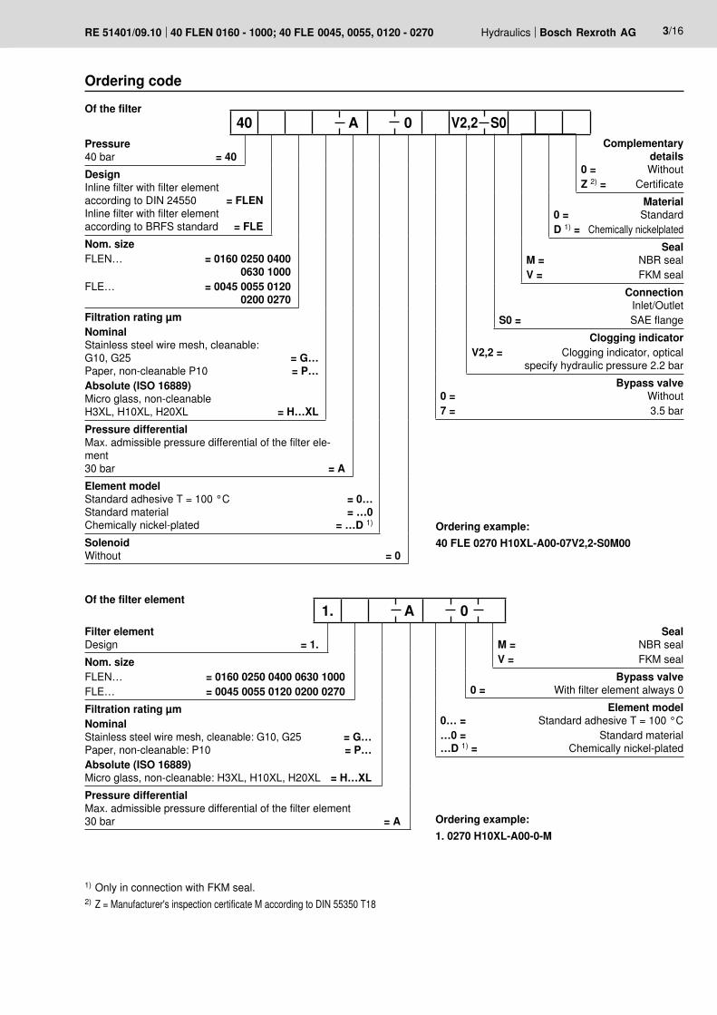
Ordering code
Pressure40 bar = 40
DesignInline filter with filter elementaccording to DIN 24550 = FLENInline filter with filter elementaccording to BRFS standard = FLENom. sizeFLEN… = 0160 0250 0400 0630 1000FLE… = 0045 0055 0120 0200 0270Filtration rating µmNominalStainless steel wire mesh, cleanable:G10, G25 = G…Paper, non-cleanable P10 = P…Absolute (ISO 16889)Micro glass, non-cleanableH3XL, H10XL, H20XL = H…XLPressure differentialMax. admissible pressure differential of the filter ele-ment30 bar = AElement modelStandard adhesive T = 100 °C = 0…Standard material = …0Chemically nickel-plated = …D 1)
SolenoidWithout = 0
Complementary details
0 = WithoutZ 2) = Certificate
Material0 = StandardD 1) = Chemically nickelplated
SealM = NBR sealV = FKM seal
ConnectionInlet/Outlet
S0 = SAE flange Clogging indicator
V2,2 = Clogging indicator, optical specify hydraulic pressure 2.2 bar
Bypass valve0 = Without7 = 3.5 bar
40 A 0 V2,2 S0
1) Only in connection with FKM seal.2) Z = Manufacturer's inspection certificate M according to DIN 55350 T18
Ordering example:40 FLE 0270 H10XL-A00-07V2,2-S0M00
Of the filter element
Filter elementDesign = 1.Nom. sizeFLEN… = 0160 0250 0400 0630 1000FLE… = 0045 0055 0120 0200 0270Filtration rating µmNominalStainless steel wire mesh, cleanable: G10, G25 = G…Paper, non-cleanable: P10 = P…Absolute (ISO 16889)Micro glass, non-cleanable: H3XL, H10XL, H20XL = H…XLPressure differentialMax. admissible pressure differential of the filter element30 bar = A
SealM = NBR sealV = FKM seal
Bypass valve0 = With filter element always 0
Element model0… = Standard adhesive T = 100 °C…0 = Standard material…D 1) = Chemically nickel-plated
1. A 0
Ordering example:1. 0270 H10XL-A00-0-M
Of the filter
4/16 Bosch Rexroth AG Hydraulics 40 FLEN 0160 - 1000; 40 FLE 0045, 0055, 0120 - 0270 RE 51401/09.10
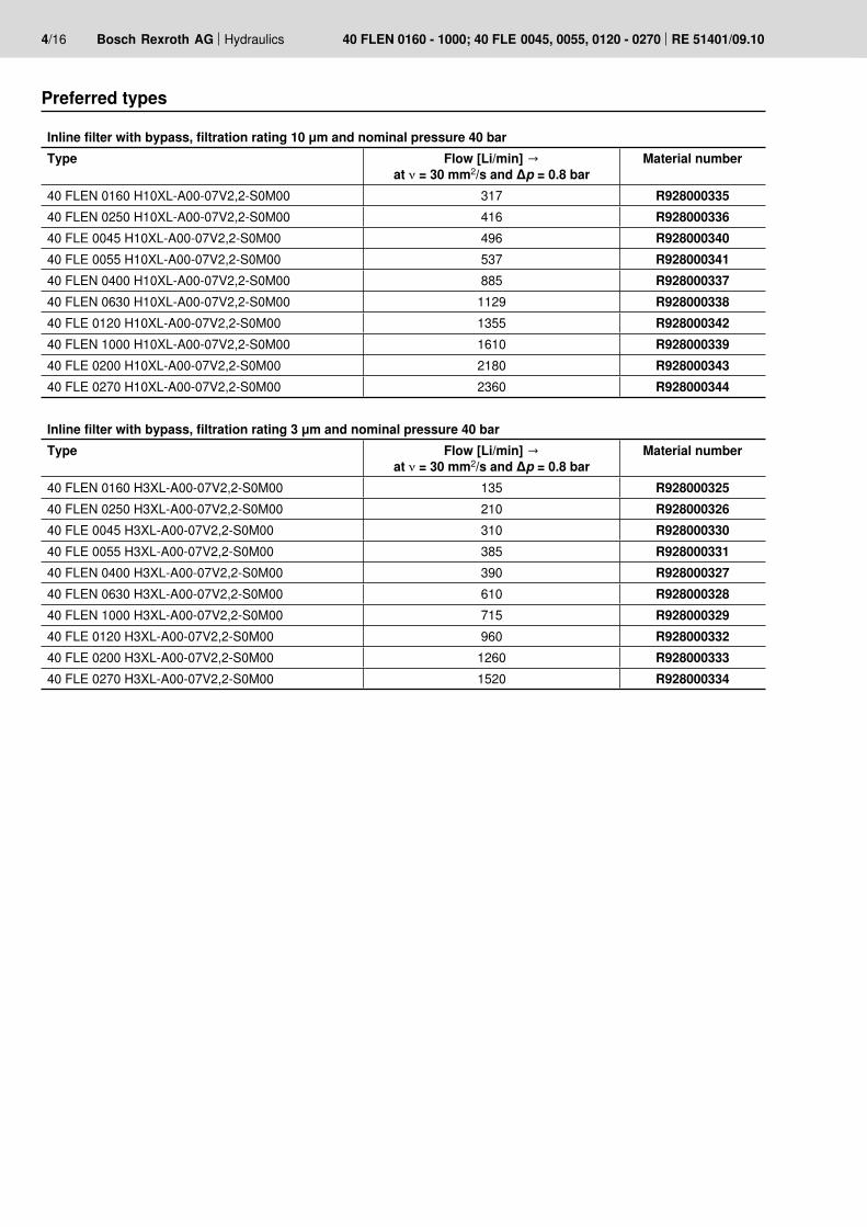
Preferred types
Inline filter with bypass, filtration rating 10 μm and nominal pressure 40 barType Flow [Li/min] →
at ν = 30 mm2/s and Δp = 0.8 barMaterial number
40 FLEN 0160 H10XL-A00-07V2,2-S0M00 317 R92800033540 FLEN 0250 H10XL-A00-07V2,2-S0M00 416 R92800033640 FLE 0045 H10XL-A00-07V2,2-S0M00 496 R92800034040 FLE 0055 H10XL-A00-07V2,2-S0M00 537 R92800034140 FLEN 0400 H10XL-A00-07V2,2-S0M00 885 R92800033740 FLEN 0630 H10XL-A00-07V2,2-S0M00 1129 R92800033840 FLE 0120 H10XL-A00-07V2,2-S0M00 1355 R92800034240 FLEN 1000 H10XL-A00-07V2,2-S0M00 1610 R92800033940 FLE 0200 H10XL-A00-07V2,2-S0M00 2180 R92800034340 FLE 0270 H10XL-A00-07V2,2-S0M00 2360 R928000344
Inline filter with bypass, filtration rating 3 μm and nominal pressure 40 barType Flow [Li/min] →
at ν = 30 mm2/s and Δp = 0.8 barMaterial number
40 FLEN 0160 H3XL-A00-07V2,2-S0M00 135 R92800032540 FLEN 0250 H3XL-A00-07V2,2-S0M00 210 R92800032640 FLE 0045 H3XL-A00-07V2,2-S0M00 310 R92800033040 FLE 0055 H3XL-A00-07V2,2-S0M00 385 R92800033140 FLEN 0400 H3XL-A00-07V2,2-S0M00 390 R92800032740 FLEN 0630 H3XL-A00-07V2,2-S0M00 610 R92800032840 FLEN 1000 H3XL-A00-07V2,2-S0M00 715 R92800032940 FLE 0120 H3XL-A00-07V2,2-S0M00 960 R92800033240 FLE 0200 H3XL-A00-07V2,2-S0M00 1260 R92800033340 FLE 0270 H3XL-A00-07V2,2-S0M00 1520 R928000334

54
M12
x 1
Ø19
,6
[2.12]
[0.7
7]
M12
x 1
Ø19
,6
41,5 [1.63]
[0.7
7]
Hydraulics Bosch Rexroth AGRE 51401/09.10 40 FLEN 0160 - 1000; 40 FLE 0045, 0055, 0120 - 0270 5/16
Ordering example: Pressure filter with mechanical optical clogging indicator for pnom. = 40 bar [580 psi] with bypass valve, nominal size 270, with filter element 10 μm and electronic switching element M12x1 with 1 switching point for pressure fluid mineral oil HLP according to DIN 51524.
Filter: 40 FLE 0270 H10XL-A00-07V2,2-S0M00 Material number: R928000344 Clogging indicator: ABZFV-E1SP-M12X1-1X/-DIN Material number: R901025339
Plug-in connectors according to IEC 60947-5-2 (dimensions in mm [inch])
Plug-in connector for K24 4-pin, M12 x 1with screwed connection, cable fitting Pg9.
Material no. R900031155
Plug-in connector for K24-3m 4-pin, M12 x 1with moulded in PVC cable, 3 m long.Line cross-section: 4 x 0.34 mm2
Core marking: 1234
BrownWhiteBlueBlack
Material no. R900064381
For electronic switching element with round plug-in connection M12 x 1
For additional round plug-in connections, see data sheet 08006.
Ordering details: Electronic switching element for clogging indicator
Rexroth power unit accessories FilterClogging indicatorElectronic switching element with 1 switching point (changeover)round plug-in connection M12x1 = E1SP-M12X1Electronic switching element with 2 switching points (normally open/normally closed), 75%, 100%, round plug-in connection M12x1, 3 LED = E2SP-M12X1Electronic switching element with 2 switching points (normally open/normally closed), 75%, 100%, signal suppression up to 30 °Cround plug-in connection M12x1, 3 LED = E2SPSU-M12X1
–DIN = Identification for DIN and SAE models
Unit series1X = Unit series 10 to 19
(10 to 19: unchanged installation and connection dimensions)
ABZ F V 1X –DIN
Electronic switching element Material no.ABZFV-E1SP-M12X1-1X/-DIN R901025339ABZFV-E2SP-M12X1-1X/-DIN R901025340ABZFV-E2SPSU-M12X1-1X/-DIN R901025341
100%2475%
1(+)
3(–)
2K2100%
4
K175% 1(+)
3(–)K2K1
S175% S2-100%
2
4
1(+)
3(–)
B
A
B
A
6/16 Bosch Rexroth AG Hydraulics 40 FLEN 0160 - 1000; 40 FLE 0045, 0055, 0120 - 0270 RE 51401/09.10
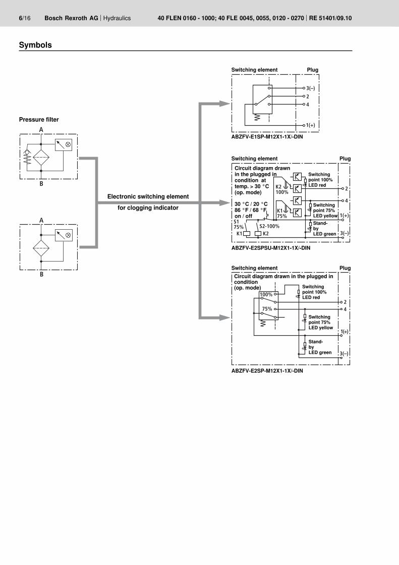
Pressure filter
Symbols
Switching element Plug
Switching point 100% LED red
Switching point 75% LED yellowStand-by LED green
Circuit diagram drawn in the plugged in condition at temp. > 30 °C (op. mode)
30 °C / 20 °C86 °F / 68 °Fon / off
Electronic switching elementfor clogging indicator
ABZFV-E1SP-M12X1-1X/-DIN
ABZFV-E2SPSU-M12X1-1X/-DIN
ABZFV-E2SP-M12X1-1X/-DIN
Switching element Plug
Switching point 100% LED red
Switching point 75% LED yellow
Stand-by LED green
Circuit diagram drawn in the plugged in condition (op. mode)
Switching element Plug

Hydraulics Bosch Rexroth AGRE 51401/09.10 40 FLEN 0160 - 1000; 40 FLE 0045, 0055, 0120 - 0270 7/16
Electronic (electric switching element)Electrical connection Round plug-in connection M12 x 1, 4-pinContact load, direct voltage A max. 1Voltage range E1SP-M12x1 V DC/AC max. 150
E2SP V DC 10 to 30Max. switching capacity with ohmic loads 20 VA; 20 W; (70 VA)Switching type E1SP-M12x1 Changeover
E2SP-M12x1 Normally open at 75% of the response pressure Normally closed at 100% of the response pressure
E2SPSU-M12x1 Normally open at 75% of the response pressureNormally closed at 100% of the response pressureSignal switching through at 30 °C [86 °F], Return switching at 20 °C [68 °F]
Display via LEDsin the electronic switching element E2SP...
Stand-by (LED green); 75% switching point (LED yellow)100% switching point (LED red)
Type of protection according to EN 60529 IP 65For direct voltage above 24 V a spark suppression is to be provided to protect the switching contacts.
Technical data (For applications outside these parameters, please consult us!)
Weight Electronic switching element: – with round plug-in connection M12 x 1 kg [lbs] 0.1 [0.22]

30025020015010050
8
7
6
5
4
3
2
1
0 400300200100
7
6
5
4
3
2
1
0
700500400300200100
6
4
3
2
1
0 600
7
5
500400300200100
5
4
3
2
1
0 600400300200100
5
4
3
2
1
0 500
1000400200
6
4
3
2
1
0 600
5
800
8/16 Bosch Rexroth AG Hydraulics 40 FLEN 0160 - 1000; 40 FLE 0045, 0055, 0120 - 0270 RE 51401/09.10
H3XL…0160
Diffe
rent
ial p
ress
ure
[bar
] →
Flow [L/min] →
H3XL…0250
Diffe
rent
ial p
ress
ure
[bar
] →
Flow [L/min] →
H3XL…0400
Diffe
rent
ial p
ress
ure
[bar
] →
Flow [L/min] →
Characteristic curves H3XL…
H3XL…0045
Diffe
rent
ial p
ress
ure
[bar
] →
Flow [L/min] →
An optimum filter selection is made possible by using our “BRFilterSelect” computer programme.
Oil viscosity:
Specific weight: < 0.9 kg/dm3
Δp-Q characteristic curves for complete filters recommended initial Δp for design = 0.8 bar 120 mm2/s
46 mm2/s30 mm2/s
H3XL…0055
Diffe
rent
ial p
ress
ure
[bar
] →
Flow [L/min] →
H3XL…0630
Diffe
rent
ial p
ress
ure
[bar
] →
Flow [L/min] →

1400400200
4
3
2
1
0 600 800 12001000
1200400
6
4
3
1
0
5
800
2
1600 2000 1200400
4
3
1
0
5
800
2
1600 24002000
6
20050
2
0 100
1
300 350
4
3
150 250 200
2
0 100
1
400 500
4
3
300
1200400200
4
3
2
1
0 600
8
800 1000 1400
5
6
7
Hydraulics Bosch Rexroth AGRE 51401/09.10 40 FLEN 0160 - 1000; 40 FLE 0045, 0055, 0120 - 0270 9/16
H3XL…0120
Diffe
rent
ial p
ress
ure
[bar
] →
Flow [L/min] →
H3XL…0200
Diffe
rent
ial p
ress
ure
[bar
] →
Flow [L/min] →
H3XL…0270
Diffe
rent
ial p
ress
ure
[bar
] →
Flow [L/min] →
H10XL…0160
Diffe
rent
ial p
ress
ure
[bar
] →
Flow [L/min] →
Characteristic curves H3XL… und H10XL…
H10XL…0250
Diffe
rent
ial p
ress
ure
[bar
] →
Flow [L/min] →
An optimum filter selection is made possible by using our “BRFilterSelect” computer programme.
Oil viscosity:
Specific weight: < 0.9 kg/dm3
Δp-Q characteristic curves for complete filters recommended initial Δp for design = 0.8 bar 120 mm2/s
46 mm2/s30 mm2/s
H3XL…1000
Diffe
rent
ial p
ress
ure
[bar
] →Flow [L/min] →
2
0
1
400
3
1600800 2000
4
1200
200
2
0 100
1
400 500
3
300 600 200
2
0 100
1
400 500
3
300 700600
2,0
0
1,0
400
2,5
1200800 1600
1,5
0,5
200
2
0
1
400
3
1000600
4
800 200
2
0
1
400
3
1200600 800 14001000
10/16 Bosch Rexroth AG Hydraulics 40 FLEN 0160 - 1000; 40 FLE 0045, 0055, 0120 - 0270 RE 51401/09.10
H10XL…1000
Diffe
rent
ial p
ress
ure
[bar
] →
Flow [L/min] →
H10XL…0045
Diffe
rent
ial p
ress
ure
[bar
] →
Flow [L/min] →
H10XL…0055
Diffe
rent
ial p
ress
ure
[bar
] →
Flow [L/min] →
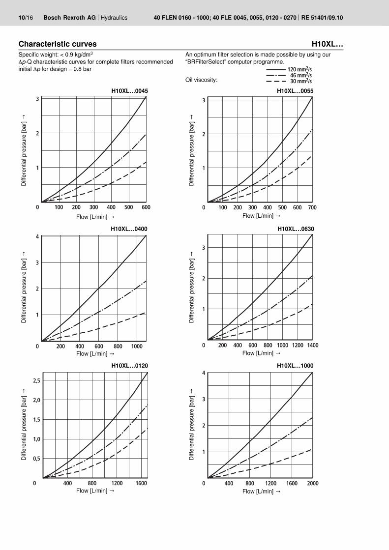
Characteristic curves H10XL…An optimum filter selection is made possible by using our “BRFilterSelect” computer programme.
Oil viscosity:
Specific weight: < 0.9 kg/dm3
Δp-Q characteristic curves for complete filters recommended initial Δp for design = 0.8 bar 120 mm2/s
46 mm2/s30 mm2/s
H10XL…0120
Diffe
rent
ial p
ress
ure
[bar
] →
Flow [L/min] →
H10XL…0400
Diffe
rent
ial p
ress
ure
[bar
] →
Flow [L/min] →
Diffe
rent
ial p
ress
ure
[bar
] →
H10XL…0630
Flow [L/min] →
2,0
0
1,0
400
2,5
2000800 2400
1,5
0,5
16001200
2,0
0
1,0
500
2,5
25001000 3000
1,5
0,5
20001500
3,0
Hydraulics Bosch Rexroth AGRE 51401/09.10 40 FLEN 0160 - 1000; 40 FLE 0045, 0055, 0120 - 0270 11/16
H10XL…0200
Diffe
rent
ial p
ress
ure
[bar
] →
Flow [L/min] →
H10XL…0270
Diffe
rent
ial p
ress
ure
[bar
] →Flow [L/min] →
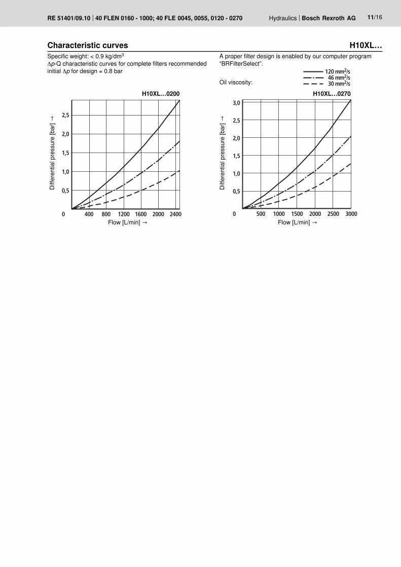
Characteristic curves H10XL…A proper filter design is enabled by our computer program “BRFilterSelect”.
Oil viscosity:
Specific weight: < 0.9 kg/dm3
Δp-Q characteristic curves for complete filters recommended initial Δp for design = 0.8 bar 120 mm2/s
46 mm2/s30 mm2/s
12/16 Bosch Rexroth AG Hydraulics 40 FLEN 0160 - 1000; 40 FLE 0045, 0055, 0120 - 0270 RE 51401/09.10
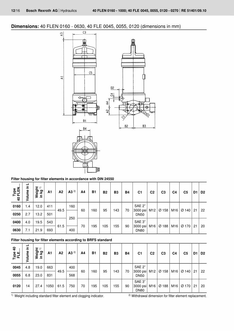
Dimensions: 40 FLEN 0160 - 0630, 40 FLE 0045, 0055, 0120 (dimensions in mm)
Type
40
FLE
N…
Volu
me i
n L
Wei
ght
in k
g 1)
A1 A2 A3 2) A4 B1 B2 B3 B4 C1 C2 C3 C4 C5 D1 D2
0160 1.4 12.0 41149.5
16060 160 95 143 70
SAE 2” 3000 psi
DN50M12 Ø 158 M16 Ø 140 21 22
0250 2.7 13.2 501250
0400 4.0 19.5 54361.5 70 195 105 155 90
SAE 3” 3000 psi
DN80M16 Ø 188 M16 Ø 170 21 20
0630 7.1 21.9 693 400
Filter housing for filter elements in accordance with DIN 24550
1) Weight including standard filter element and clogging indicator. 2) Withdrawal dimension for filter element replacement.
Filter housing for filter elements according to BRFS standard
Type
40
FLE…
Volu
me i
n L
Wei
ght
in k
g 1)
A1 A2 A3 2) A4 B1 B2 B3 B4 C1 C2 C3 C4 C5 D1 D2
0045 4.8 19.0 66349.5
40060 160 95 143 70
SAE 2” 3000 psi
DN50M12 Ø 158 M16 Ø 140 21 22
0055 6.8 23.0 831 568
0120 14 27.4 1050 61.5 750 70 195 105 155 90SAE 3”
3000 psi DN80
M16 Ø 188 M16 Ø 170 21 20

Hydraulics Bosch Rexroth AGRE 51401/09.10 40 FLEN 0160 - 1000; 40 FLE 0045, 0055, 0120 - 0270 13/16
Dimensions: 40 FLEN 1000, 40 FLE 0200 - 0270 (dimensions in mm)Ty
pe
40 F
LEN…
Volu
me i
n L
Wei
ght
in k
g 1)
A1 A2 A3 2) A4 A5 B1 B2 B3 B4 C1 C2 C3 C5 D1
1000 12 50 553 90 260 65 118 113 113 183SAE 4”
3000 psi DN100
M16 Ø 216 Ø 200 26
Filter housing for filter elements in accordance with DIN 24550
Mounting area “B” forClogging indicator
Mounting area “A”for clogging indicator
View Z
Filter housing for filter elements according to BRFS standard
Type
40
FLE
…
Volu
me i
n L
Wei
ght
in k
g 1)
A1 A2 A3 2) A4 A5 B1 B2 B3 B4 C1 C2 C3 C5 D1
0200 22 60 91190
758320
310118 113 113 183
SAE 4” 3000 psi DN100
M16 Ø 188 Ø 200 260270 28 70 1145 992 540
1) Weight including standard filter element and clogging indicator. 2) Withdrawal dimension for filter element replacement.
14/16 Bosch Rexroth AG Hydraulics 40 FLEN 0160 - 1000; 40 FLE 0045, 0055, 0120 - 0270 RE 51401/09.10
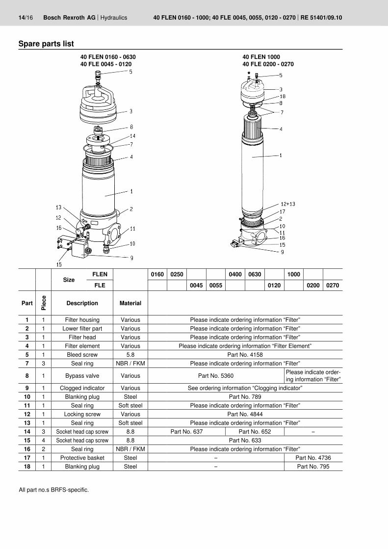
Spare parts list
All part no.s BRFS-specific.
40 FLEN 0160 - 063040 FLE 0045 - 0120
40 FLEN 1000 40 FLE 0200 - 0270
SizeFLEN 0160 0250 0400 0630 1000FLE 0045 0055 0120 0200 0270
Part
Piec
e
Description Material
1 1 Filter housing Various Please indicate ordering information “Filter”2 1 Lower filter part Various Please indicate ordering information “Filter”3 1 Filter head Various Please indicate ordering information “Filter”4 1 Filter element Various Please indicate ordering information “Filter Element”5 1 Bleed screw 5.8 Part No. 41587 3 Seal ring NBR / FKM Please indicate ordering information “Filter”
8 1 Bypass valve Various Part No. 5360 Please indicate order-ing information “Filter”
9 1 Clogged indicator Various See ordering information “Clogging indicator”10 1 Blanking plug Steel Part No. 78911 1 Seal ring Soft steel Please indicate ordering information “Filter”12 1 Locking screw Various Part No. 484413 1 Seal ring Soft steel Please indicate ordering information “Filter”14 3 Socket head cap screw 8.8 Part No. 637 Part No. 652 –15 4 Socket head cap screw 8.8 Part No. 63316 2 Seal ring NBR / FKM Please indicate ordering information “Filter”17 1 Protective basket Steel – Part No. 473618 1 Blanking plug Steel – Part No. 795

Hydraulics Bosch Rexroth AGRE 51401/09.10 40 FLEN 0160 - 1000; 40 FLE 0045, 0055, 0120 - 0270 15/16
Spare parts (insert for DIN and SAE filters)
DIN = Identification for DIN and SAE models
Sealing materialM = See table belowV = See table below
Unit series1X = Unit series 10 to 19
(10 to 19; unchanged installation and connection dimensions)
Rexorth power unit accessories
FilterClogging indicatorMechanical optical clogging indicatorfor low-pressure filtersswitching point 2.2 bar [32 psi] = NV2
Mechanical opticalClogging indicator ABZ F V NV2 1X DIN
Mechanical opticalClogging indicator Material no.
ABZFV-NV2-1X/M-DIN R901025312
The ordering details for filter elements can be found on page 3.
Sealing material and surface coating for pressure fluidsOrdering detail
Mineral oils Sealing material Element model and material
Mineral oil HLP according to DIN 51524 M ...0
Fire-resistant hydraulic fluidsEmulsions HFA-E according to DIN 24320 M ...0Synthetic water solutions HFA-S according to DIN 24320 M ...DWater solutions HFC according to VDMA 24317 M ...DPhosphate esters HFD-R according to VDMA 24317 V ...DOrganic esters HFD-U according to VDMA 24317 V ...D
Hydraulic fluids that are fast biodegradableTriglycerides (rape seed oil) HETG according to VDMA 24568 M ...D
Synthetic esters HEES according to VDMA 24568 V ...DPolyglycoles HEPG according to VDMA 24568 V ...D
Sealing kits must be ordered by stating the complete part key.
Bosch Rexroth Filtration Systems GmbHHardtwaldstraße 43, 68775 Ketsch, GermanyPOB 1120, 68768 Ketsch, GermanyPhone +49 (0) 62 02 / 6 03-0Fax +49 (0) 62 02 / 6 03-1 [email protected]
© This document, as well as the data, specifications and other informa-tion set forth in it, are the exclusive property of Bosch Rexroth AG. It may not be reproduced or given to third parties without its consent.The data specified above only serve to describe the product. No state-ments concerning a certain condition or suitability for a certain applica-tion can be derived from our information. The information given does not release the user from the obligation of own judgment and verification. It must be remembered that our products are subject to a natural process of wear and aging.
16/16 Bosch Rexroth AG Hydraulics 40 FLEN 0160 - 1000; 40 FLE 0045, 0055, 0120 - 0270 RE 51401/09.10
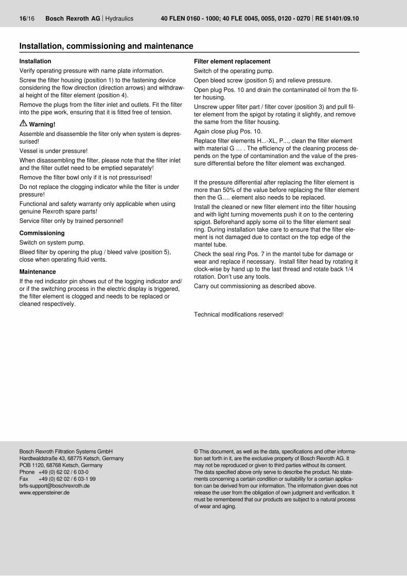
Installation, commissioning and maintenanceInstallationVerify operating pressure with name plate information.Screw the filter housing (position 1) to the fastening device considering the flow direction (direction arrows) and withdraw-al height of the filter element (position 4).Remove the plugs from the filter inlet and outlets. Fit the filter into the pipe work, ensuring that it is fitted free of tension.
Warning!Assemble and disassemble the filter only when system is depres-surised!Vessel is under pressure!When disassembling the filter, please note that the filter inlet and the filter outlet need to be emptied separately!Remove the filter bowl only if it is not pressurised!Do not replace the clogging indicator while the filter is under pressure!Functional and safety warranty only applicable when using genuine Rexroth spare parts!Service filter only by trained personnel!
CommissioningSwitch on system pump.Bleed filter by opening the plug / bleed valve (position 5), close when operating fluid vents.
MaintenanceIf the red indicator pin shows out of the logging indicator and/or if the switching process in the electric display is triggered, the filter element is clogged and needs to be replaced or cleaned respectively.
Filter element replacementSwitch of the operating pump.Open bleed screw (position 5) and relieve pressure.Open plug Pos. 10 and drain the contaminated oil from the fil-ter housing.Unscrew upper filter part / filter cover (position 3) and pull fil-ter element from the spigot by rotating it slightly, and remove the same from the filter housing.Again close plug Pos. 10.Replace filter elements H...-XL, P..., clean the filter element with material G … . The efficiency of the cleaning process de-pends on the type of contamination and the value of the pres-sure differential before the filter element was exchanged.
If the pressure differential after replacing the filter element is more than 50% of the value before replacing the filter element then the G…. element also needs to be replaced.Install the cleaned or new filter element into the filter housing and with light turning movements push it on to the centering spigot. Beforehand apply some oil to the filter element seal ring. During installation take care to ensure that the filter ele-ment is not damaged due to contact on the top edge of the mantel tube.Check the seal ring Pos. 7 in the mantel tube for damage or wear and replace if necessary. Install filter head by rotating it clock-wise by hand up to the last thread and rotate back 1/4 rotation. Don’t use any tools.Carry out commissioning as described above.
Technical modifications reserved!
Top Related