


Languages
Pages
Legal


Page | 1
INFLUENCE OF SLENDERNESS ON THE BEHAVIOUR OF MICROPILES
Gonçalves, João, Instituto Superior Técnico (IST), Lisboa, Portugal, [email protected]
ABSTRACT
The aim of this study is to develop a critical analysis for the buckling of micropiles with high slenderness, taking
into account the action of axial loading.
In order to clarify the definition, classification, application and methods of design of micropiles was added like
additional information, pointing out the buckling compression.
To better understand the sensitivity of various parameters in micropile-soil interaction, taking into account the
lateral instability, the author proceeded to a numerical approach. The modelling of the structure is performed
using a calculation model by 2D finite elements.
It’s also described the main design and execution criteria considered in the solution for the underpinning of
pavements and structures of industrial warehouses located at the site of the “Antiga Trefilaria”, as well as the
monitoring the of the superstructure behaviour in response to the developed work. It’s also presented the results
of loading tests performed in micropiles, considering the heterogeneity of geological formations, which
confirmed the perfect adaptation of this indirect foundation solution to the conditions of local geotechnical and
geological scenario.
Finally, it presents some general considerations about this work.
1. INTRODUCTION The use of micropiles has changed significantly in recent years since its first use in the 50’s, when Dr. Fernando
Lizzi developed the concept of micropiles groups in historic buildings. The first application consisted on lightly
loaded groups of piles that were designed to reinforce unstable soil mass. Currently the micropiles have a wide
application in geotechnical structures, rehabilitation projects, and strengthening of new structures in urban areas
and such solutions have evolved to high load capacity systems [5].
This document contains a review of relevant historical research, as well as reports of recent experiences obtained
directly from applications on micropiles with high load capacity solutions.
In order to understand the technique of micropiles, Chapter 2 of this document intends primarily to describe the
existent solutions (features, definition, types and benefits) and construction procedures associated with
micropiles. The preparation of this text has resulted from a literature research, therefore much of the information
that is contained there, can be found in the texts mentioned in the bibliography.
In Chapter 3 is discussed the main methods of geotechnical design used for this type of foundations. This chapter
also deals with the considerations about the structural design of the micropiles, and focuses on practical aspects
of construction and connection details to the superstructure.
The Chapter 4 aims to provide a description of procedures to study the issue of buckling of micropiles as well as
recommendations for conducting its analysis in a systematic way. The analysis of this phenomenon is completed
by a parametric study using a calculation model through finite elements method.
In Chapter 5 the intention was to follow a practical example of the increasing occupation of alluvial soils with
inherent problems of resistance and deformability. This chapter presents the adopted solutions for the treatment
of the soil foundation, the ground floors foundations and the underpinning of the foundations existing in the
industrial warehouses, in steal structures, at the place of the “Antiga Trefilaria”, in Sacavém, near the “Trancão”
River (Figure 1). With the intention of drawing conclusions about the assumptions and adopted criteria, it was
performed a characterization of the area, under analyzes, to have a known geotechnical scenario and were also
preformed two static load tests in the same area in order to optimize the final design solution and to predict the
settlement of the very compressible areas, like soft areas.

Page | 2
2. MICROPILES Originally designed in Italy in the early 50’s, the solution of micropiles came up with the need to improve the
foundations of historic buildings, or act as a method of rehabilitation, taking into account the damages during the
2nd World War. It was necessary a solution compatible with different types of soils, which could be applied in
reduced areas and minimizing the effects on adjacent structures [8].
The original concept of micropiles was due to Dr. Fernando Lizzi that in Fondedile Construction Company had
developed a solution called "Pali Radice" (root cuttings) whose aim would be to create a foundation system
similar to the roots of trees. The success of this application was so huge that drew the attention of all
professionals in geotechnical engineering and led to a quick expansion of this building process, not only the
great ability to withstand axial forces but also by the versatile application in different geological sceneries [5].
The micropiles can be defined as high slenderness element composed of cement grout sealing and / or injection,
and having a steel profile as reinforcement that resists to the majority of the total design loads. This load is
mainly resisted by the steel and conveys to the surrounding soil primarily by lateral friction.
The main characteristic of this type of indirect foundation is a high load capacity that is based primarily on the
lateral friction (in the presence of solid rock, the tip resistance could also become significant), which can be
provided even for a weak soil features [2].
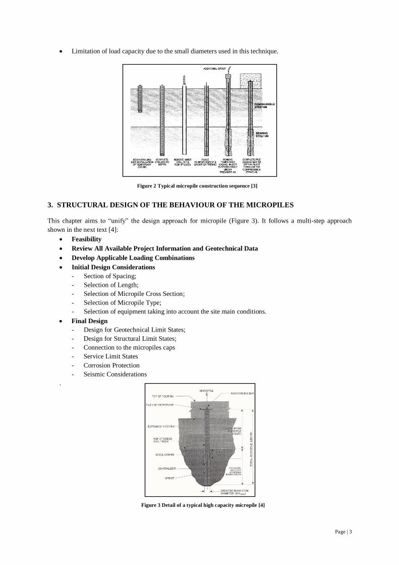
The micropiles, like the conventional piles, can be drilled or driven, although the typical construction involves
four key stages (Figure 2):
Drilling;
Placement of reinforcement;
Sealing;
Injection of cement grout at high pressure.
The micropiles are a specialized tool from a range of geotechnical solutions to solve very specific problems, on
which the mechanical characteristics of the soil do not provide bearing capacity in surface areas, being necessary
to achieve great depths to obtain appropriate values of resistance and limit settlements to acceptable values.
These elements are also included in the type of foundation of structures subjected to anti-gravity action.
However, applications of micropiles can be divided into two groups, structural support (foundation of new
structures, improving the ability of foundations, reinforcement for seismic actions ...) and overall reinforcement
of the soil "in-situ” (reduction settlements, stabilization of slopes ...).
This method has a wide range of benefits (regardless the type of micropiles and construction process), which, in
fact, explains its increasingly use:
Little disruption of the surrounding soil in terms of vibration and noise;
High load capacity in terms of the diameter of the micropiles, even in poor soil characteristics;
Allow an excellent control of settlements;
Possibility of working in limited areas;
Good income in its implementation.
The disadvantages of this solution:
It’s a specialized intervention with the need of very specialized firms, with appropriate equipment and
manpower;
It doesn´t support instability phenomena in soft/incompetent soils where there is the danger of buckling;
Figure 1 View of the intervened warehouses [1]
Page | 3
Limitation of load capacity due to the small diameters used in this technique.
3. STRUCTURAL DESIGN OF THE BEHAVIOUR OF THE MICROPILES
This chapter aims to “unify” the design approach for micropile (Figure 3). It follows a multi-step approach
shown in the next text [4]:
Feasibility
Review All Available Project Information and Geotechnical Data
Develop Applicable Loading Combinations
Initial Design Considerations
- Section of Spacing;
- Selection of Length;
- Selection of Micropile Cross Section;
- Selection of Micropile Type;
- Selection of equipment taking into account the site main conditions.
Final Design
- Design for Geotechnical Limit States;
- Design for Structural Limit States;
- Connection to the micropiles caps
- Service Limit States
- Corrosion Protection
- Seismic Considerations
.
Figure 2 Typical micropile construction sequence [3]
Figure 3 Detail of a typical high capacity micropile [4]
Page | 4
4. BUCKLING OF MICROPILES
The structural capacity of a micropile is often determined by the geotechnical capability dictated by lateral
friction between the grout used in the micropile and the surrounding soil, rather to strength of the elements that
constitute it. However it’s reasonable to believe that when intersecting soft soil, monogranular saturated sandy
soil with potential for liquefaction, micropile could be heavy loaded, and the buckling may be a phenomenon
that will affect the load capacity of micropile [6].
This chapter intends to present some fundamental concepts that characterize the behaviour of the structures about
the buckling phenomena and present a brief parametric analysis on the influence of certain factors on the
question of buckling. This analysis consisted of applying the finite element analysis of linear stability of a
micropile confined by the soil environment to determine the critical loads and buckling modes based on the
consideration of geometrically nonlinear effects.
The program used was ADINA (Automatic Dynamic Incremental Nonlinear Analyses, Version 8.5) which aims,
among other things, to do a linear and nonlinear finite element analysis. For the study in question was used a tool
for linear analysis of buckling, in order to obtain the lowest critical buckling load for different scenarios (Figure
4 and Figure 5), then the analyzes proceeds to a variation of parameters as the modulus of soil reaction, section,
moment of inertia and length of micropiles, determining, in each case, the lowest critical load of buckling of the
structure.
In those several scenarios it was considered three types of micropiles, as illustrated in Table 1.
Adopted the yield stress value of 500 MPa and modulus of elasticity of steel was considered equal to 200 GPa.
Name Micropile tube
Outside Diameter
[mm]
Thickness
[mm] Area [m
2]
fyd
[MPa]
Yield load
[kN]
Cross Section 1 (CT1) 118 x 7,5 [mm] 118 7,5 26,04 500 1301,8
Cross Section 2 (CT2) 118 x 10,6 [mm] 118 10,6 35,77 500 1788,3
Cross Section 3 (CT3) 170 x 10,6 [mm] 170 10,6 53,08 500 2654,1
Table 1 Characteristics of micropile
In order to use the finite element method to analyze the buckling problem it is necessary to admit that the
material (micropile and soil) has linear elastic behaviour (linearity) and that the displacements and deformations,
as it comes to stability analysis, require a nonlinear behaviour.
Despite a more realistic study should consider a behaviour between an analysis in plane stress and plane strain
state, it was assumed, due to the very close results provided by the program in both analyses, that the final results
would focus in the analyses in plane stress (plane laminar structure subject to existing efforts only on its plan
where it’s acceptable as valid the following assumptions: xz = yz = z = 0).
The results for the cases 1 to 6 can be analyse in tables below (Table 2, 3 and 4), which show the values of
critical load and the deflection in each case.
For cases 3 and 4 it is possible to observe the results of the variation of critical load with the reaction module of
the soil in Figure 6.
From the analysis of previous data it shows that in most situations the critical load is higher than the design load
and in the areas where the phenomenon of buckling is a constraint, the reaction modules of soil are reduced to
very low values. With the same result it is possible to observe that the modulus of reaction influences the critical
load, this is to say, the critical load of instability increases as the surrounding soil improves its mechanical
properties, so the buckling phenomenon is most likely to occur in soils with very low resistance properties.
Looking at the deflection graphics it is possible to watch that with the increase of the transversal dimensions, the
control is more efficient over the horizontal displacements suffered by micropiles, while with the variation of
slenderness is observed an excessive increase in the amplitude of the horizontal displacements.

Page | 5
Figure 5 Case 5 and 6
Figure 4 Case 1 to 4

Page | 6
0,00
5,00
10,00
15,00
20,00
25,00
0,00 0,50 1,00 1,50 2,00
De
pth
[m
]
Deflection [m]
0,00
10,00
20,00
30,00
40,00
50,00
60,00
0,00 2,00 4,00 6,00 8,00
De
pth
[m
]
Deflection [m]
Secção Transversal 1
Secção Transversal 2
Secção Transversal 3
0,00
5,00
10,00
15,00
20,00
25,00
30,00
35,00
40,00
45,00
50,00
-0,02 -0,01 0,00 0,01 0,02 0,03
De
pth
[m
]
Deflection [m]
cenário 4,ST1, Ks=800kPa, com mola
cenário4,ST1, Ks=800kPa
0,00
2000,00
4000,00
6000,00
8000,00
10000,00
0 5000 10000 15000
Cri
tica
l Lo
ad [
kN]
Modulus of lateral reaction of the soil [kPa]
0,00
2000,00
4000,00
6000,00
8000,00
10000,00
0 5000 10000 15000
Cri
tica
l Lo
ad [
kN]
Modulus of lateral reaction of the soil [kPa]
Table 2 Achievements case 1 (left) and case 2 (right)
Case 2 - Critical Load - Pcr (kN)
Micropile Critical Load (kN)
(CT1) 118 x 7,5 [mm] 0,79
(CT2) 118 x 10,6 [mm] 1,03
(CT3) 170 x 10,6 [mm] 3,34
Case 1 - Critical Load – Pcr (kN)
Micropile Critical Load (kN)
(CT1) 118 x 7,5 [mm] 4,93
(CT2) 118 x 10,6 [mm] 6,42
(CT3) 170 x 10,6 [mm] 20,89
Table 3 Achievements - case 5
Case 5 - Critical Load - Pcr (kN)
KS (kN/m2)
Micropiles
118 x 7,5 [mm]
800 1051,0
Figure 8 Representation of displacements – case 1 (left) and case 2 (right)
Figure 6 Variation of critical load with the module reaction – case 3 (left) and case 4 (right)
Cross Section 2
Cross Section 3
Figure 7 Deflections for pre-selected cases
Case 5, CT1, Ks=800kPa, with
spring
Case 4, CT1, Ks=800kPa
Cross
Section 1

Page | 7
0,00
5,00
10,00
15,00
20,00
25,00
30,00
35,00
40,00
45,00
50,00
-0,02 -0,01 0,00 0,01 0,02
De
pth
[m
]
Deflection[m]
1º modo de instabilidade
2º modo de instabilidade
3º modo de instabilidade
With the consulting of the previous data it is possible to state that the condition of considering an elastic support
(spring) increases the value of critical load condition by changing the deflection form, which proves to be an
important phenomenon when analyzing the critical load of the system micropile-soil.
From the analysis of the results in case 6, it is also possible to state that the phenomenon of buckling
compression is not determinant relatively to the yield resistance of the micropiles (Pcr=4910 kN˃Nrd=3315,3
kN).
5. MONITORING OF A WORK WITH THE USE OF MICROPILES TECHNOLOGY
The aim of this chapter is to present the observation of a work, where the technology adopted were drilled and
driven micropiles. Another goal was to study the main design and execution criteria for the adopted solutions for
the underpinning of pavements (that concerns the treatment of the soil solution of the foundation and ground
floors) and structures of industrial buildings located on the site of the old Trefilaria, next to the Trancão River.
Regarding the main existing constraints, the solutions have been developed in order to allow the excavation of
fill materials and execution of hollow section micropiles, to support a new reinforced concrete slab. The main
constraints were the following:
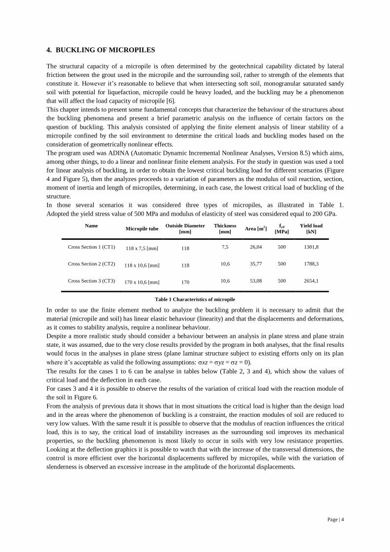
Geological and geotechnical – the buildings were already built over a layer of fill, resting over a
geological scenario, dominated by the alluvial basin of the Trancão River. With the geologic /
geotechnical information collected from site investigation as well from the monitoring and
instrumentation devices (Erro! A origem da referência não foi encontrada.) it was considered
that the land is submitted mainly to vertical movements due to the consolidation of the very soft soil.
That was caused by the increase of the stress due to the weight of landfills (with thicknesses of around
4m), transmitted to the alluvial mud and very soft clay (0.4 MPa <qc <1 MPa). This process resulted in
settlement rates over time of about 5mm per week which, according to the preformed studies, spreaded
over several years until reaching values of around 1.0 m [9].
It was identified the following soil groups classified from the surface:
Landfill Deposits (consisting of mainly sandy-clay with rocky areas, with thicknesses between 4.50 m
and 5.50 m); Alluvial Deposits (underlying the previous line, with thicknesses between 12.0 m and 23.0
m, and sometimes with interbedded sandy lenticules, which conditioned the phenomena of
consolidation in terms of modeling and consolidation. These formations are primarily composed of
silty-clay mud with small sandy-silt lenticules); Miocene Substrate (underlying formations mentioned
above), this material that can be described like: fine sand silt, more or less muddy, with some stiff mud,
medium to fine sandy silt, slightly muddy, sand grains-carbonated; clays silt, micaceous, fossiliferous
calcareous, fractured and with friable passages; clay marl.
Case 6
Buckling Mode Critical Load - Pcr (kN)
1st Instability Mode 4910
2nd
Instability Mode 4918
3rd
Instability Mode 5173
Table 4 Achievements - case 6
Figure 9 Deflections for case 6
1st
Instability
Mode
2nd
Instability Mode
3rd
Instability
Mode
Page | 8
Figure 10 Geotechnical profile [1]
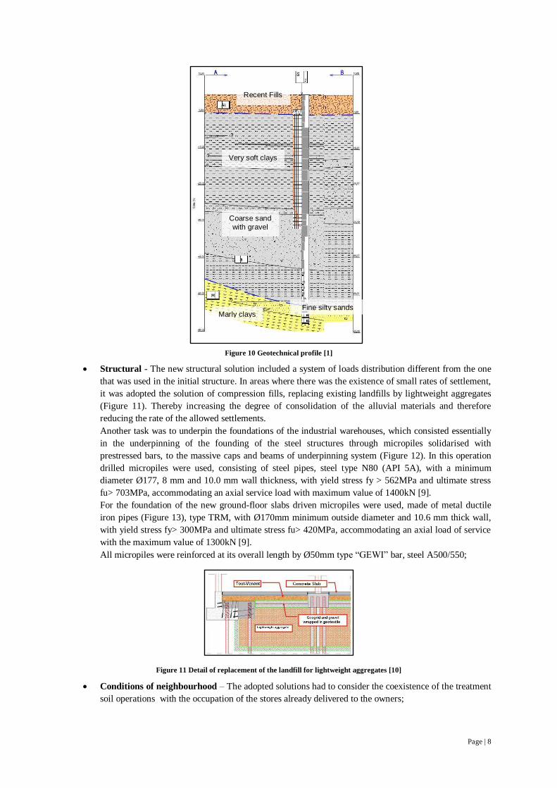
Structural - The new structural solution included a system of loads distribution different from the one
that was used in the initial structure. In areas where there was the existence of small rates of settlement,
it was adopted the solution of compression fills, replacing existing landfills by lightweight aggregates
(Figure 11). Thereby increasing the degree of consolidation of the alluvial materials and therefore
reducing the rate of the allowed settlements.
Another task was to underpin the foundations of the industrial warehouses, which consisted essentially
in the underpinning of the founding of the steel structures through micropiles solidarised with
prestressed bars, to the massive caps and beams of underpinning system (Figure 12). In this operation
drilled micropiles were used, consisting of steel pipes, steel type N80 (API 5A), with a minimum
diameter Ø177, 8 mm and 10.0 mm wall thickness, with yield stress fy > 562MPa and ultimate stress
fu> 703MPa, accommodating an axial service load with maximum value of 1400kN [9].
For the foundation of the new ground-floor slabs driven micropiles were used, made of metal ductile
iron pipes (Figure 13), type TRM, with Ø170mm minimum outside diameter and 10.6 mm thick wall,
with yield stress fy> 300MPa and ultimate stress fu> 420MPa, accommodating an axial load of service
with the maximum value of 1300kN [9].
All micropiles were reinforced at its overall length by Ø50mm type “GEWI” bar, steel A500/550;
Conditions of neighbourhood – The adopted solutions had to consider the coexistence of the treatment
soil operations with the occupation of the stores already delivered to the owners;
Figure 11 Detail of replacement of the landfill for lightweight aggregates [10]
Recent Fills
Very soft clays
Coarse sand
with gravel
Marly clays Fine silty sands

Page | 9
-4,5
-4
-3,5
-3
-2,5
-2
-1,5
-1
-0,5
0
0 5 10 15 20 25 30 35 40 45 50 55 60 65
dis
pla
ce
me
nt
(mm
)
depth (m)
Incremental Displacement Curves Normalized to RE2
1st cycle: 0-480 kN
1st cycle: 480-980 kN
1st cycle: 980-1620 kN
2nd cycle: 0-980 kN
2nd cycle: 480-980 kN
2nd cycle: 980-1470 kN
2nd cycle: 1470-1970 kN
3rd cycle: 0-480 kN
3rd cycle: 480-980 kN
3rd cycle: 980-1620 kN
Average Disp. Curve
Adjusted Displ. Curve
Duration of the work – Structural and geotechnical solutions were chosen in order to meet the owner
deadlines;
This chapter also presents a micropile full scale compression load test, which scheme could be seen in Figure 14.
This test was made to evaluate the performance of an early solution of strengthen foundations as well as of soil
improvement, when submitted to downdrag phenomena caused by the consolidation of surrounding soil. The
data represented below is related to previous trials in a drilled micropile, at the site where the works took place,
and was performed with the aim of characterizing the soil behaviour, assessing the adequacy of construction
method and test the solution behaviour.
In the following figures it’s represented the displacement vs. depth considering the cycles defined above, as well
as the estimation of other quantities (Figure 15 until Figure 19).
Figure 12 Detail of underpinning of the superficial foundations inside the existing metal structure
Figure 13 View of driven equipment of micropiles and placement the reinforcement bar
Figure 14 The micropile load test scheme [1]
Figure 15 Cycles stage [1]

Page | 10
0
2
4
6
8
10
12
14
16
18
20
22
24
26
28
30
32
34
36
38
40
-1800 -1300 -800 -300
de
pth
(m
)
(kN)Theoretical Axial Load
máx. before cycles stage
máx. axial force distribution
0
2
4
6
8
10
12
14
16
18
20
22
24
26
28
30
32
34
36
38
40
-50 -25 0 25 50 75 100125
de
pth
(m
)
(kN)Shear Load
0
2
4
6
8
10
12
14
16
18
20
22
24
26
28
30
32
34
36
38
40
-120-90 -60 -30 0 30 60 90
de
pth
(m
)
(kNm)Bending Moment
-60
-55
-50
-45
-40
-35
-30
-25
-20
-15
-10
-5
0
0 20 40 60 80 100 120 140 160 180 200
Ve
rtic
al S
ett
lem
en
t(m
m)
days
micropile headby micropile compressionby micropile bending
Movements due to micropile bending stabilized after 50 days, denoting effective lateral soil support
head load partial discharge
0
4
8
12
16
20
24
28
32
36
40
44
48
52
56
60
64
68
0 100 200 300
de
pth
(m
)
(kPa)
máx. 3rd cycle
máx. shaft shear distribution
EAsteelx1,35
Estimated Shaft Shear Distribuition
0
4
8
12
16
20
24
28
32
36
40
44
48
52
56
60
64
68
0 500 1000 1500 2000
de
pth
(m
)
(kN)Estimated Load Distribution
máx. 3rd cycle
máx. force distribution
1620 kN from
head load plus
142 kN from
drag load
large amount of shaft resistance yet not mobilized
EAsteelx1,35
From the data interpretation it was possible to achieve the following observations:
The ultimate load that the test shows is approximately 1800 kN, representing 55% of the micropile
design load without lateral instability;
Micropile execution method significantly weakened surrounding soil mechanical properties, especially
in the very soft clays layer, where water was used during the drilling operations;
High shaft resistance in the sandy deposits (expecting drag residual load);
At ultimate test load, a lateral soil pressure was away from failure;
The structural behavior of the micropile is very limited by lateral instability.
Figure 18 Axial Load, Bending Moment and Shear Load Diagrams [1]
Figure 17 Rod Extensometers Interpretation [1]
Figure 16 Data Assembly [1]

Page | 11
0
2
4
6
8
10
12
14
16
18
20
22
24
26
28
30
32
34
36
38
40
0 2000 4000 6000
de
pth
(m
)
(kPa)Modulus of Lat. Reaction of the Soil (Es)
máx. before cycles stage
máx. axial force distribution
Theoretical value expected
185 kPa, ~ 12% of the theoretical value expected!!!Installation procedure responsibility?
0
2
4
6
8
10
12
14
16
18
20
22
24
26
28
30
32
34
36
38
40
-300 -100 100 300 500 700d
ep
th (m
)(kPa)Lateral Soil Pressure
máx. before cycles stage
máx. axial force distributionInitial lateral pressure
absolute final lateral pressureoverburden pressure
fill
closer normal stresses
meaning better stress stateve
ry s
oft
cla
ys (
tota
l str
esse
s)sa
nd
(eff
ecti
ve s
tres
ses)
0
2
4
6
8
10
12
14
16
18
20
22
24
26
28
30
32
34
36
38
40
0 100 200 300 400 500 600 700
de
pth
(m
)
Micropile Safety Analysis
|máx. normal stress| (MPa)
fy (MPa)
Mresist.(kNm)
|Msolic.| (kNm)
elastic approach
plastic approach
near failure
-25
-20
-15
-10
-5
0
0 10 20 30 40 50 60
dis
pla
cem
en
ts (
mm
)
depth (m)
1st cycle
Estacas Cravadas (1000kN)
Estacas Cravadas (500kN)
Estaca à Rotação (980 kN)
Estaca à Rotação (490 kN) -30
-25
-20
-15
-10
-5
0
0 10 20 30 40 50 60
dis
pla
cem
en
ts (
mm
)
depth (m)
3rd cycle
-20
-15
-10
-5
0
0 5 10 15 20 25 30 35 40 45 50 55 60 65
de
slo
cam
en
to (
mm
)
depth (m)
2nd cycle
Estacas Cravadas (1500kN)
Estacas Cravadas (1000kN)
Estacas Cravadas (500kN)
Estaca à Rotação (1470 kN)
Estaca à Rotação (980 kN)
Estaca à Rotação (490 kN)
It was also preformed a full scale compression load test in a driven micropile similar to the previous one. The
data represented below is related to a comparison between the evolution of displacement vs depth in driven and
drilled micropiles.
From the data interpretation it was possible to achieve that driven micropiles allow small settlements compared
to those produced in drilled micropiles.
The instrumentation and observation of the consolidation process of the alluvial materials for about 4 years was
also analysed. The Instrumentation and Monitoring plan was developed in order to enable a systematic control of
the parameters considered relevant to the study of the evolution of settlements in the area, as well as to ensure a
proactive monitoring of the behavior of the structure, particularly during operations of charging and excavation.
Figure 19 Soil response and micropile safety analysis [1]
Driven Micropile (500 kN) Driven Micropile (500 kN) Drilled Micropile (980 kN) Drilled Micropile (490 kN)
Driven Micropile (1500 kN) Driven Micropile (1000 kN) Driven Micropile (500 kN) Drilled Micropile (1470 kN) Drilled Micropile (980 kN) Drilled Micropile (490 kN)
Figure 20 Rod Extensometers: driven micropiles vs drilled micropiles
Page | 12
The observation was implemented before the beginning of the work (underpinning of the foundation) and has
shown to be a key tool, to the confirmation of the solution efficiency. This can be shown in Figure 21 where it’s
possible to confirm that the muds were submitted to a consolidation process, which could reach, in some places,
rates of settlement of 1.0 mm / day [11].
In this stage were installed, before and during construction, the following equipments: 100 topographic targets
(to assess the overall and differential settlement between different points of the structure); 11 benchmarks (to
assess the vertical settlements of the industrial buildings facades located in the most problematic places); 3
inclinometers within some of the boreholes of the geotechnical site investigation (to assess the potential
susceptibility of alluvial formations to make horizontal movements in depth, once the Miocene substrate showed
an elevated susceptibility towards the River Trancão); 4 inclinometers within some micropiles (to assess the
possible micropiles horizontal displacements) and 5 piezometers (to assess changes in the piezometer level).
The devices installed were read, in the first instance, once a week to collect the maximum information in order to
analyze the evolution of settlements and in the second stage (after complete most of the excavation and
micropiles works) readings were taken monthly, since that the magnitude of the rate of evolution of the
movements recorded were significantly lower.
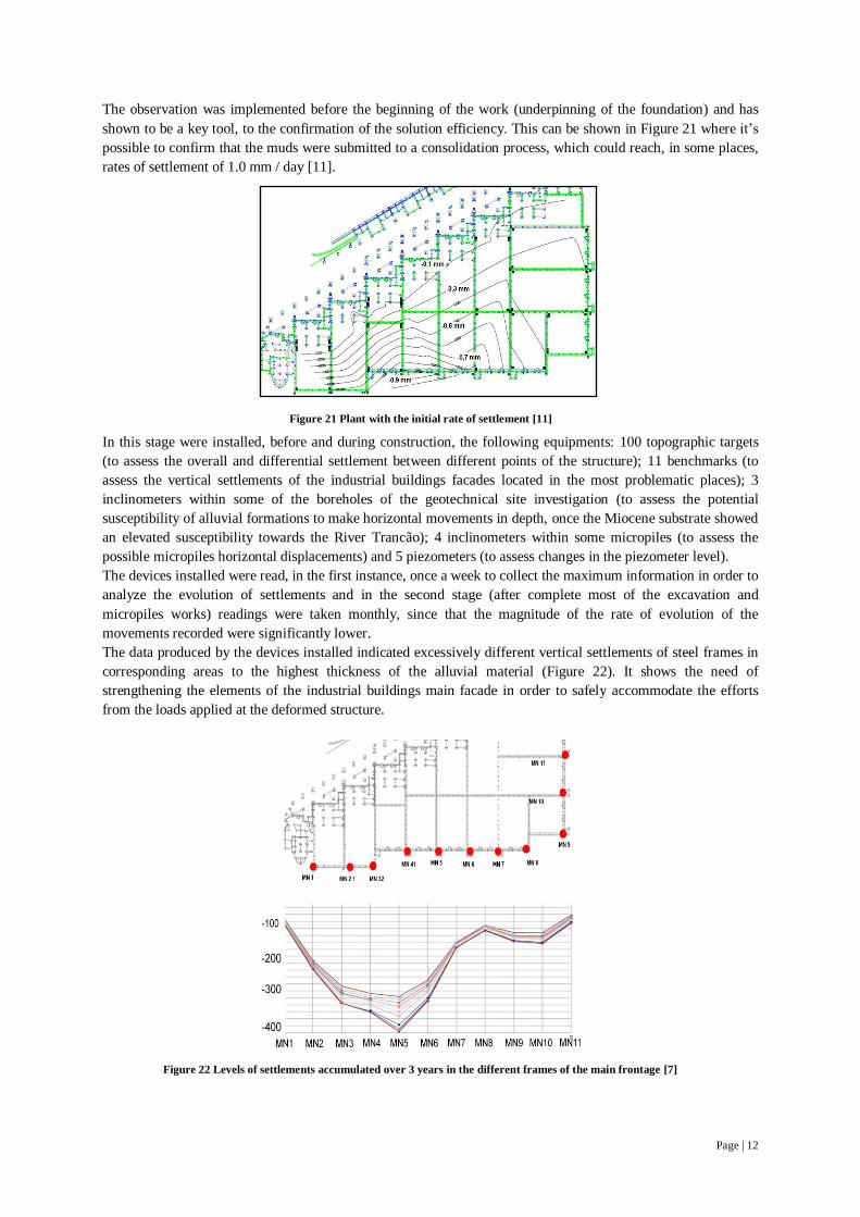
The data produced by the devices installed indicated excessively different vertical settlements of steel frames in
corresponding areas to the highest thickness of the alluvial material (Figure 22). It shows the need of
strengthening the elements of the industrial buildings main facade in order to safely accommodate the efforts
from the loads applied at the deformed structure.
Figure 21 Plant with the initial rate of settlement [11]
Figure 22 Levels of settlements accumulated over 3 years in the different frames of the main frontage [7]

Page | 13
6. CONCLUSIONS
In general, the results indicates no need for checking the ultimate limit state of buckling in micropiles, which
does not invalidate (knowing the high slenderness of micropiles) a tight control of some key factors such as
elastic critical load, the axis midline deviation, geometric imperfections of the section and soil-micropile
interaction.
In the adopted model, which had as main goal to measure the conditioning of the phenomenon of buckling by
compression in the structural design of the micropiles, it was noticed that the buckling should not be a concern
for the types of micropiles used in this study, but it can exist some cases in which buckling can be a major
constraint in a project. Micropiles apart from being slender structural elements capable of carrying large loads,
when penetrate soft soils are in danger of buckling even when in some design codes the require safety check
against buckling is not needed.
Within the presented underpinning case study, the instrumentation and monitoring plan associated with an
adequate characterization of the geological and a geotechnical scenario in a stage before the project started,
proved to be a fundamental tool to support and justify the proposed rehabilitation and strengthening design.
During the construction and exploitation, the instrumentation and monitoring, is also justified as a tool for
analyzing and controlling the behaviour of the structure, confirming the suitability of the adopted solutions.
The usefulness of load tests on piles presented themselves as important prediction tool, because it can assess the
adequacy of the construction method, to determine the behavior of a pile and provide a representative
consideration of the surrounding terrain. It also clarifies in terms of: ultimate limit states (load capacity) and
serviceability limit states (deformation, creep behavior and elastic / plastic in the discharge).
7. ACKNOWLEDGMENTS
The author wishes to express his gratitude to the Prof. Alexandre Pinto, Prof. Jaime Santos, Prof. Luis Castro,
Prof. Carlos Tiago, Eng. Rui Tomásio (JetSJ Geotecnia Lda), Engº Rui Bibi (RODIO) and Engª Ana Catarina
Ferrão (Kerpro) that somehow contributed to this work.
8. REFERENCES
[1] Bibi, R. (2008), Micropile Load Test Analysis, Rodio, London.
[2] Brito, J. (1999), Micro-Estacas, Instituto Superior Técnico, Lisboa.
[3] Bruce, D.A. (2008), The History of Micropiles in North America, ADSC - The International Association of
Foundation Drilling, Las Vegas.
[4] Bruce, D.A, Cadden, A. W. e Sabatini, P.J. (2005), Practical Advice for Foundation Design – Micropiles
for Structural Support (Contemporary Issues in Foundation Engineering), Geo-Frontiers Geotechnical Special
Publications, Texas, 25 pp.
[5] Bruce, D.A, DiMillio, A. F. e Juran, E.G. (1997), Micropiles: The state of Practice Part 1: Characteristics,
Definitions and Classifications - Ground improvement, Thomas Telford, Vol.1.
[6] Cadden, A. e Gómez, J. (2002), Buckling of Micropiles, ADSC-IAF Micropile Committee, West Chester.
[7] Fileno, B. (2008), Polígono de actividades económicas, Sacavém - Nota Técnica, GAUSS - Topometria e
Monitorização Estrutural S.A., Lisboa.
[8] Lizzi, F. (1982), Static restoration of monuments, Sagep Publisher, Genoa.
[9] Pinto, A. (2010), Soluções de recalçamento de fundações e pavimentos de edifícios industriais no local da
antiga trefilaria - Sacavém, JetSJ geotecnia, Lisboa.
[10] Pinto, A. e Tomásio, R. (2008), Projecto De Execução De Tratamento Dos Solos De Fundação (Antiga
Trefilaria – Parque Oriente) - Memória Descritiva e Justificativa, JetSJ geotecnia, Lisboa.
[11] Pinto, A., Tomásio, R., Neto, R., Ferrão, A. E Aguiar, O. (2010) Underpinning solutions of industrial
buildings located at the old steel processing plant area – Sacavém, Lisboa
Top Related