


Languages
Pages
Legal


TECHNICAL SPECIFICATION No.:
I-ET-3010.1M-5266-630-P4X-001
CLIENT: SRGE
SHEET: 1
of 22
PROJECT: REFERENCE BASIC DESIGN 10010563980010
UNIT: BUZIOS
DP&T-SRGE
TITLE:
TOPSIDE'S MECHANICAL HANDLING PROCEDURES
NP-1
ESUP
MICROSOFT WORD / V. 2003 / I-ET-3010.1M-5266-630-P4X-001_0.DOC
INDEX OF REVISIONS
REV. DESCRIPTION AND / OR REVISED SHEETS
0
ORIGINAL ISSUE
REV. 0 REV. A REV. B REV. C REV. D REV. E REV. F REV. G REV. H
DATE MAR/19/19
DESIGN ESUP
EXECUTION BFRANCA
CHECK GONZALEZ
APPROVAL TMCAMPOS
THE INFORMATION CONTAINED IN THIS DOCUMENT IS PETROBRAS PROPERTY AND MAY NOT BE USED FOR PURPOSES OTHER THAN THOSE SPECIFICALLY INDICATED HEREIN. THIS FORM IS PART OF PETROBRAS N-381 REV. K.

TECHNICAL SPECIFICATION Nº:
I-ET-3010.1M-5266-630-P4X-001 REV.
0
UNIT:
BUZIOS SHEET
2 of 22
TITLE: TOPSIDE'S MECHANICAL HANDLING PROCEDURES
NP-1
ESUP
INDEX
1 SCOPE .................................................................................................................................................. 3
2 PURPOSE ............................................................................................................................................. 3
3 ABBREVIATIONS ................................................................................................................................. 3
4 REFERENCES ...................................................................................................................................... 3
4.1 APPLICABLE CODES AND STANDARDS ........................................................................................... 3
4.2 BASIC DESIGN REFERENCE DOCUMENTS ..................................................................................... 4
5 DESIGN REQUIREMENTS .................................................................................................................. 4
5.1 GENERAL ............................................................................................................................................. 4
5.2 OPERATION ENVIRONMENT ............................................................................................................. 4
5.3 ACCELERATIONS AND MOTIONS ..................................................................................................... 4
5.4 SERVICE LIFE ...................................................................................................................................... 4
5.5 MAIN LOADS PRELIMINARY LIST ...................................................................................................... 5
5.6 HANDLING AND TRANSFER MATRIX ................................................................................................ 5
5.7 SAFETY ................................................................................................................................................ 6
5.8 MAINTENANCE .................................................................................................................................... 6
5.9 PAINTING ............................................................................................................................................. 6
5.10 PACKAGE AND SKID MOUNTED EQUIPMENT ................................................................................. 7
5.11 MODULE DESIGN ................................................................................................................................ 7
6 OPERATION ......................................................................................................................................... 7
6.1 TYPES OF LOGISTIC OPERATIONS .................................................................................................. 7
6.2 MAXIMUM OPERATIONAL CONDITIONS ........................................................................................... 7
6.3 OPERATING SCHEDULE..................................................................................................................... 8
7 CARGO HANDLING RESOURCES AND EQUIPMENT ...................................................................... 8
7.1 TOPSIDES SCOPE OF SUPPLY ......................................................................................................... 8
7.2 OFFSHORE CRANES (FOR INFORMATION) ..................................................................................... 8
7.3 MONORAILS, TROLLEYS AND HOISTS ............................................................................................. 9
7.4 DIESEL-HYDRAULIC DECK TROLLEY ............................................................................................. 10
7.5 LAYDOWN AREAS ............................................................................................................................. 11
7.6 REMOVABLE HATCHES .................................................................................................................... 11
7.7 REMOVABLE PANELS ....................................................................................................................... 12
7.8 DAVITS ............................................................................................................................................... 12
7.9 MISCELLANEOUS ITEMS .................................................................................................................. 12
8 HANDLING DUTIES ........................................................................................................................... 13
8.1 INCOMING AND OUTGOING LOADS RELATED WITH THE TOPSIDES OPERATION ................. 13
8.2 TOPSIDES .......................................................................................................................................... 13
8.3 MAIN DECK ........................................................................................................................................ 16
9 HANDLING AND LIFTING DEVICES ................................................................................................. 17

TECHNICAL SPECIFICATION Nº:
I-ET-3010.1M-5266-630-P4X-001 REV.
0
UNIT:
BUZIOS SHEET
3 of 22
TITLE: TOPSIDE'S MECHANICAL HANDLING PROCEDURES
NP-1
ESUP
1 SCOPE
a) This Technical Specification is focused on the design requirements for mechanical handling procedures and equipment.
b) All mechanical handling procedures associated with the FPSO Topside, Hull and its systems (for example, personnel transfer, handling of provisions, garbage disposal and handling of supplies for the accommodation) are excluded from the scope of this document.
2 PURPOSE
a) The purpose of this document is:
� To identify and describe the different types of logistic operations and associated handling tasks,
� To establish the main parameters and limiting conditions for each type of handling operation, so as to enable safe and efficient handling of all materials, supplies, components and equipment required for the FPSO Topside operations and maintenance,
� In addition, to define the minimum resources and devices to be provided in order to fulfill the cargo handling needs.
3 ABBREVIATIONS
A&EM Automation & Electrical Module
A&C Automation and Control
API American Petroleum Institute
CS Classification Society
FPSO Floating Production, Storage & Offloading
HSE Health, Safety and Environmental
HVAC Heating, Ventilation and Air Conditioning
NR Normas Regulamentadoras (Brazilian Labor Ministry Regulations)
PS Portside
SB Starboard
SS Stainless Steel
SWL Safe Work Load
TG Turbogenerator
TBD To be defined
UPS Uninterruptible Power System
4 REFERENCES
All mechanical handling facilities and equipment shall comply with the requirements herein stated and with the following codes, standards, regulations and reference documents:
4.1 APPLICABLE CODES AND STANDARDS
API 2C Specification for Offshore Cranes (Design Guide)
API RP 14J Recommended Practice for Design and Hazards Analysis for Offshore Production Facilities
ISO 20340 PAINTS AND VARNISHES – Performance Requirements for Protective Paint Systems for Offshore and Related Structures
NR-1 Disposições Gerais (General Guidelines)
TECHNICAL SPECIFICATION Nº:
I-ET-3010.1M-5266-630-P4X-001 REV.
0
UNIT:
BUZIOS SHEET
4 of 22
TITLE: TOPSIDE'S MECHANICAL HANDLING PROCEDURES
NP-1
ESUP
NR 10 Segurança em Instalações e Serviços em Eletricidade (Safety in Electrical Facilities and Services)
NR-11 Transporte, Movimentação, Armazenagem e Manuseio de Materiais (Materials Transportation, Handling and Storage)
NR-17 Ergonomia (Ergonomics)
NR 26 Sinalização de Segurança (Safety Signaling)
NR-30 – Anexo II Plataformas e Instalações de Apoio (Platforms and Support Facilities)
NR-37 Gestão de Segurança e Saúde no Trabalho
Government codes, regulations, ordinances or rules applicable to the equipment in Brazil shall prevail over the requirements of this specification, including reference codes and standards, only if more stringent.
4.2 BASIC DESIGN REFERENCE DOCUMENTS
DR-ENGP-1.3-R.2 SAFETY PHILOSOPHY
DR-ENGP-1.4-R.2 REQUIREMENTS FOR SAFETY STUDIES
DR-ENGP-1.15 COLOR CODING
I-DE-3010.1M-1200-942-P4X-002 GENERAL ARRANGEMENT
I-DE-3010.1M-5400-94A-P4X-001 AREA CLASSIFICATION – GENERAL
I-ET-3010.1M-5266-631-P4X-001 OFFSHORE CRANE
I-ET-3010.1M-1350-196-P4X-001 ERGONOMIC REQUIREMENTS FOR TOPSIDES
I-ET-3010.00-1200-956-P4X-002 GENERAL PAINTING
I-ET-3010.00-5140-700-P4X-002 SPECIFICATION FOR ELECTRICAL MATERIAL AND EQUIPMENT FOR OFFSHORE UNITS
I-ET-3A36.00-1000-941-PPC-001 METOCEAN DATA
I-FD-3010.1M-5266-631-P4X-001 FIXED BOOM CRANE
I-RL-3010.1M-1350-960-P4X-009 MOTION ANALYSIS
5 DESIGN REQUIREMENTS
5.1 GENERAL
All lifting and handling means shall be designed to enable transfer of loads from their assigned incoming laydown area to target location and back.
5.2 OPERATION ENVIRONMENT
All cargo handling equipment and materials shall be designed and constructed for operation in offshore marine environment, according to the parameters (temperature, relative humidity, winds etc.) described in I-ET-3A26.00-1000-941-PPC-001 – METOCEAN DATA.
Note: For dry bulb air temperature of electrical equipment, use the most critical conditions, among those defined by CS and the specific equipment documentation.
5.3 ACCELERATIONS AND MOTIONS
All cargo handling facilities shall be designed and manufactured to withstand the static and dynamic conditions described in I-RL-3010.1M-1350-960-P4X-009 – MOTION ANALYSIS
5.4 SERVICE LIFE
All cargo handling equipment and materials shall be designed and manufactured for 25 years service life without the need for major repairs or replacement of main components.
TECHNICAL SPECIFICATION Nº:
I-ET-3010.1M-5266-630-P4X-001 REV.
0
UNIT:
BUZIOS SHEET
5 of 22
TITLE: TOPSIDE'S MECHANICAL HANDLING PROCEDURES
NP-1
ESUP
5.5 MAIN LOADS PRELIMINARY LIST
a) See Attachment 1 (HOLD) for a preliminary list of relevant Topside loads that require lifting and handling, showing respective estimated weights, dimensions and handling devices to be used. This list was prepared based on reference drawings from former projects or, whenever available, on preliminary vendor information gathered during the Basic Design phase.
b) As the equipment vendors – and, in some cases, equipment or package configuration – are not yet defined at the current stage of design development, the list shall be fully revised and completed during Detail Design. Whenever required, any cargo handling needs arising from changes to equipment/ package dimensions, configuration, layout and/ or weight shall be met during Detail Design.
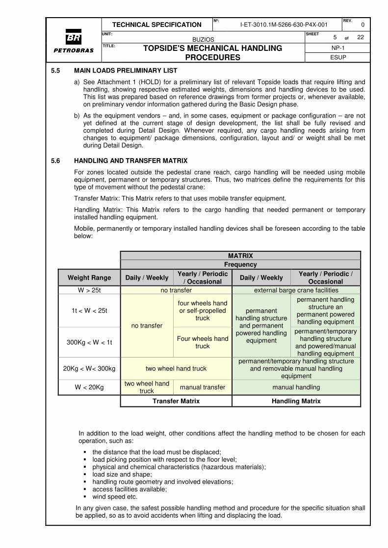
5.6 HANDLING AND TRANSFER MATRIX
For zones located outside the pedestal crane reach, cargo handling will be needed using mobile equipment, permanent or temporary structures. Thus, two matrices define the requirements for this type of movement without the pedestal crane:
Transfer Matrix: This Matrix refers to that uses mobile transfer equipment.
Handling Matrix: This Matrix refers to the cargo handling that needed permanent or temporary installed handling equipment.
Mobile, permanently or temporary installed handling devices shall be foreseen according to the table below:
In addition to the load weight, other conditions affect the handling method to be chosen for each operation, such as:
� the distance that the load must be displaced; � load picking position with respect to the floor level; � physical and chemical characteristics (hazardous materials); � load size and shape; � handling route geometry and involved elevations; � access facilities available; � wind speed etc.
In any given case, the safest possible handling method and procedure for the specific situation shall be applied, so as to avoid accidents when lifting and displacing the load.
MATRIX
Frequency
Weight Range Daily / Weekly Yearly / Periodic
/ Occasional Daily / Weekly
Yearly / Periodic / Occasional
W > 25t no transfer external barge crane facilities
1t < W < 25t
no transfer
four wheels hand or self-propelled
truck permanent
handling structure and permanent
powered handling equipment
permanent handling structure an
permanent powered handling equipment
300Kg < W < 1t Four wheels hand
truck
permanent/temporary handling structure
and powered/manual handling equipment
20Kg < W< 300kg two wheel hand truck permanent/temporary handling structure
and removable manual handling equipment
W < 20Kg two wheel hand
truck manual transfer manual handling
Transfer Matrix Handling Matrix

TECHNICAL SPECIFICATION Nº:
I-ET-3010.1M-5266-630-P4X-001 REV.
0
UNIT:
BUZIOS SHEET
6 of 22
TITLE: TOPSIDE'S MECHANICAL HANDLING PROCEDURES
NP-1
ESUP
5.6.1 Cargo handling routes shall be free from obstacles that might block or impair the displacement of trolleys and similar handling devices.
5.7 SAFETY
a) All handling operations shall be performed strictly within the specified operational limits and following the instructions established by each equipment manufacturer.
b) All cranes and handling devices shall be operated in compliance with the FPSO Safety Management System, in order to prevent accidents and material damages.
c) Safety shall be ensured throughout all handling operations by training the involved personnel, certifying handling procedures for cranes and other lifting devices, using personal protection equipment and warning signs, checking stability of tooling and structures, and providing protection against dropped objects as far as practical and in full compliance with current HSE regulations and rules.
d) Operating procedures shall include instructions to minimize travel of objects being lifted above equipment, piping manifolds and pipe racks.
e) Handling and safety instructions and device certificates shall be provided as required by the applicable rules and regulations.
f) Handling equipment intended for installation within classified areas shall be suitable for that purpose – for instance, non-sparking materials and surface finish; certified electrical equipment and components, as applicable. The relevant area classification certificates shall be provided.
g) Loose tools, accessories and equipment shall be properly stored and stowed.
h) Above 0.4 g horizontal acceleration, movable devices shall be secured to fixed structures.
i) All handling devices shall be fitted with 316 SS nameplates or permanent labels stating SWL, tag number and technical data.
5.8 MAINTENANCE
a) Topsides Layout shall be designed to enable safe and easy access and material flow, by means of transportation routes, disassembly and maintenance areas, and overhead spaces.
b) Obstruction-free areas shall be provided for extraction and maintenance of the bundles of shell-and-tube heat exchangers (or for removal of the complete exchanger, in case of fixed tubesheet), for removal of plates from plate-type heat exchangers and for removal, cleaning and inspection of printed circuit heat exchangers.
c) All parts/ components involved in maintenance shall be able to be transferred between their normal locations and the supply vessel or FPSO workshops/ laydown areas.
d) Whenever required, equipment shall be fitted with temporary guides and supports, hoisting points, A-frames and dedicated davits or lifting appliances.
e) Control valves and their actuators, and large sized valves in general, shall be removable for maintenance purposes.
f) All parts requiring regular onshore maintenance shall be removable for overhaul using dedicated means.
g) All parts which may require non-scheduled onshore maintenance shall be removable for overhaul using specific means to be fitted as and when required.
5.9 PAINTING
5.9.1 Painting Requirements
Painting requirements shall be according I-ET-3010.00-1200-956-P4X-002 (GENERAL
PAINTING).
5.9.2 Color
Color code shall be according to DR-ENGP 1.15.

TECHNICAL SPECIFICATION Nº:
I-ET-3010.1M-5266-630-P4X-001 REV.
0
UNIT:
BUZIOS SHEET
7 of 22
TITLE: TOPSIDE'S MECHANICAL HANDLING PROCEDURES
NP-1
ESUP
5.10 PACKAGE AND SKID MOUNTED EQUIPMENT
a) Suppliers shall provide each package and/ or skid mounted equipment with dedicated means for disassembly and removal of components subject to repair or maintenance, so as to bring them to the skid or package boundaries for further handling using the resources available on the Unit. Sub-assemblies, electric motors, auxiliary equipment etc. shall be provided with padeyes or equivalent lifting means.
b) Package and skid mounted equipment shall be designed and constructed considering the cargo handling needs arising from lifting and transportation, installation on site, normal operation and maintenance.
5.11 MODULE DESIGN
a) Each module supplier shall be responsible for designing and providing built-in lifting facilities within their respective scope of supply, to deliver the operation and maintenance loads up to the module limits, and for preparing the applicable operating procedures to fulfill these needs.
b) If required to bring the loads to any location out of the reach of the deck crane, then monorails, trolleys, deck trolley pathways or equivalent devices shall be provided for this purpose, in order to enable flawless material handling.
6 OPERATION
6.1 TYPES OF LOGISTIC OPERATIONS
6.1.1 Each operation described in the following sections is classified as one of the types listed below and assigned the limiting conditions for safe operation of the relevant equipment.
6.1.2 As regards mechanical handling, four categories of logistic operations are defined:
SRCL Standard Regular Consumable Logistics
SICL Standard Infrequent Consumable Logistics
SML Standard Maintenance Logistics
NSML Non-Standard Maintenance Logistics
6.1.3 Non-Standard Maintenance
a) “NSML” is defined as a maintenance event which is highly unlikely to occur throughout the FPSO expected service life. On-board lifting and handling facilities will not be provided nor designed for this type of operation, however the FPSO Topsides layout design shall be developed so as to create no major obstacles to the possible disassembly, removal and transportation of equipment, if required;
b) “NSML”-type logistic operations require external assistance as well as special procedures to be prepared by BIDDER;
c) Some examples of equipment with maintenance classified as NSML: pressure vessels, stators of large electrical machinery such as generators and gas compressors, major crane components; this list shall be supplemented during Detail Design to include all other items deemed relevant, which shall be agreed upon with Petrobras.
6.2 MAXIMUM OPERATIONAL CONDITIONS
a) For the logistic categories defined in item 6.1.2, the offshore crane shall be used in accordance with the current weather conditions. See following table:
Operation Type
Max. Lifting Weight
Significant Wave Height
Max. Roll Angle
Max. Wind Force*
SRCL 1 t 3 m 3° 5 SICL 5 t 2 m 2º 5 SML 15 t 2 m 2º 5
* Beaufort Scale

TECHNICAL SPECIFICATION Nº:
I-ET-3010.1M-5266-630-P4X-001 REV.
0
UNIT:
BUZIOS SHEET
8 of 22
TITLE: TOPSIDE'S MECHANICAL HANDLING PROCEDURES
NP-1
ESUP
b) The referred data are preliminary and shall be reviewed during Detail Design, in accordance with the actual site conditions.
6.3 OPERATING SCHEDULE
6.3.1 In normal conditions, transportation of general supplies to the FPSO will be performed by supply/
service vessels once every two weeks.
7 CARGO HANDLING RESOURCES AND EQUIPMENT
7.1 TOPSIDES SCOPE OF SUPPLY
The following types of lifting and handling devices shall be provided, as a minimum (refer to section 10 for additional details and reference sketches):
� Monorails/ runway beams � Manual, chain driven, pneumatic driven or electric motor driven hoists � Manual, chain driven or electric motor driven beam trolleys � Self-propelled diesel-hydraulic deck trolley � Overhead crane(s) � Pipe rack davits (fore and aft) � Portable davits and respective pedestals � Portable gantry cranes � Removable hatches � Removable panels � Hydraulic stackers � Hand pallet trucks � Floor cranes � Hand trolleys and trucks � Tilting floor drum stands � Lift tables � Shift skates � Manual cable pullers � Wire rope winches � Portable hoists � Rail trolleys � Beam clamps � Cylinder transport cabinets � General purpose lifting devices: tackles, slings, chains, ropes etc.
7.2 OFFSHORE CRANES (FOR INFORMATION)
Fixed boom cranes GD-5266501 & GD-5266502 are provided by HULL Contractor.
Main characteristics and some relevant operating data of the lattice-boom type offshore cranes to be installed on the Unit are given below:
a) Design and construction according to API 2C Standard, type “C” or “E”, with diesel-hydraulic drive.
b) Crane lifting capacity in accordance with Petrobras data sheet:
Operating Condition Capacity
Max. load considered for crane dimensioning SWL 25 t @ 46 m (offboard) Maximum crane boom reach 9 t @ 48 m
c) The cranes’ minimum hoisting and lowering speed have been specified so as to ensure safe off-board operations while working at the most extreme environmental conditions (winds, waves and currents) foreseen for the Unit.
d) As far as practical, lifting and handling of incoming/ outgoing cargo and also on-board load handling within the FPSO shall be performed using the deck cranes. Additional facilities are to be provided for all areas out of the cranes’ reach.

TECHNICAL SPECIFICATION Nº:
I-ET-3010.1M-5266-630-P4X-001 REV.
0
UNIT:
BUZIOS SHEET
9 of 22
TITLE: TOPSIDE'S MECHANICAL HANDLING PROCEDURES
NP-1
ESUP
e) The aft crane, is designed for daily operation, mostly handling chemicals, supplies and spare parts.
f) The fore crane is intended for maintenance support.
g) During Detail Design of the Hull, certified load charts shall be provided by crane manufacturer, specifying the maximum load for each boom radius as a function of wind speed and significant wave height during offboard operations.
h) In case of maintenance on one of the cranes, the other one shall work as a back-up, and means shall be provided to enable unimpaired material handling during the repair period, until both cranes are available again.
i) For estimated lifting frequencies associated with Topsides maintenance and operation, refer to the following table. All figures shall be confirmed during Detail Design.
Loads to be lifted Mean Interval (days)
Equipment supplies ~1.75 Chemicals (tote tanks), lubricating oils and greases ~3.5 H2S-Scavenger solid bed tote bins ~20 Equipment maintenance parts and components ~36
7.3 MONORAILS, TROLLEYS AND HOISTS
a) Hoists with trolleys running along lifting beams shall be fitted as necessary, to ensure flawless load transfer from the original locations to one of the available laydown areas or to another device for further handling using the cranes.
b) For handling procedures using monorails, trolley and hoists, or pad-eyes and hoists, the design shall consider headroom available, considering the space necessary for trolley, hoist, sling angle, equipment to be removed, etc.
c) According to the loads to be handled (see item 5.6), hoists and their respective trolleys are to be manually driven (chain type drive) or motor-driven (electric or pneumatic). See Section 10, items 04 through 08 for reference sketches.
d) Lifting beams are fitted with their respective trolleys.
e) A significant number of chain hoists foreseen within the scope of this Technical Specification are intended for infrequent use, remaining mostly out of operation. These devices, when installed outdoors in an offshore environment, require periodical inspection, maintenance, lubrication and cleaning, in order to keep them in good operating condition and to avoid damage to critical components such as gears, racks, pinions, bearings etc. Therefore, in order to minimize CapEx and maintenance, the following premises have been established for the Basic Design:
� The total quantity of hoists is to be kept as low as possible;
� On modules which require several hoists with the same capacity, it is recommended to purchase 01 (one) hoist for each SWL – or 02 (two) whenever simultaneously required for critical load transfer from one lifting beam to another;
� When not in use, the chain hoists are to be preferably stored inside a closed toolbox or cabinet within the module area, to be defined during Detail Design, or using one of the available stores on the Main Deck (by Hull Bidder);
� Whenever required for a specific handling task, the hoist is brought from its storage place and temporarily installed on the beam trolley. Heavy hoists which cannot be manually transported and installed are displaced with manual cars and lifted to their operating locations using auxiliary devices such as smaller hoists, or shieves attached to beam clamps or padeyes.
f) Whenever the local arrangement restrictions do not allow the installation of running trolleys, welded padeyes (to be defined during Detail Design) shall be installed as required, with sufficient loading capacity to lift the relevant loads on each area. Portable hoists or other lifting devices may be temporarily installed on those padeyes. Loads shall be placed on hand trucks, pallet trucks or similar devices for further transfer to their final location.
g) Beams for lifting service shall be designed to withstand the main loads which require handling for maintenance or repair, located within their respective areas, and the materials/ consumables normally used on the area.

TECHNICAL SPECIFICATION Nº:
I-ET-3010.1M-5266-630-P4X-001 REV.
0
UNIT:
BUZIOS SHEET
10 of 22
TITLE: TOPSIDE'S MECHANICAL HANDLING PROCEDURES
NP-1
ESUP
h) Trolleys running on beams transversely installed with respect to the FPSO main axis shall be fitted with locking devices or positive traction (rack and pinion or sprocket wheel and geared rack), to ensure safe handling conditions under the maximum expected FPSO lateral motions and accelerations.
i) Electric motor driven devices shall be provided with fail-safe automatic brakes, released when the motor is energized.
j) Refer to Attachment 2 (HOLD) for a preliminary list of trolleys and hoists to be provided on the FPSO Topsides. This list shall be fully reviewed and completed during Detail Design, to meet the specific requirements of each selected equipment and with the final layout of each package and module.
7.4 DIESEL-HYDRAULIC DECK TROLLEY
7.4.1 Diesel-hydraulic self-propelled trolley – 22t
a) One (01) diesel-hydraulic self-propelled trolley shall be provided, with 22 t loading capacity,
intended for the transfer of maintenance loads exceeding 5 t on the Process Plant Deck; see Section 10, item 01 for reference sketch.
b) It shall run on dedicated area along the centerline of the main handling route underneath the Pipe
Rack, which connects the fore and aft regions of the Process Plant Deck;
c) The full length of the main handling route shall be structurally reinforced to withstand the displacement of the fully loaded trolley (approx. 32 t static load), and also considering the applicable dynamic factor arising from the lowering of loads onto the self-propelled trolley cargo deck.
7.4.2 Diesel-hydraulic self-propelled trolley – 5 t
a) One (01) diesel-hydraulic self-propelled trolley shall be provided, with 5 t loading capacity,
intended for general cargo handling on the Process Plant Deck and, if required, on the Main Deck. See Section 10, item 01 for reference sketch.
b) This vehicle may be transferred between both previously mentioned deck levels as required, using the deck cranes, by means of the built-in lifting lugs provided on the trolley.
c) It shall be able to run along the Pipe Rack main handling route, and also on the process plant modules, through specific handling and maintenance routes.
d) On the modules specifically intended for deck trolley operation, the handling routes and maintenance areas shall be structurally reinforced to withstand loads corresponding to the trolley’s own weight plus the heaviest part to be handled on each area (approx. 8 t static load), and also considering the applicable dynamic factor arising from the lowering of loads onto the trolley cargo deck. During Detail Engineering, this condition shall be demonstrated by means of the relevant calculations.
e) Modules intended for deck trolley operation shall be interconnected, and also connected to the pipe rack handling route by means of access paths reinforced to withstand the expected loads as stated on item (d).
f) Module suppliers shall design the above referred internal paths for deck trolley displacement within the modules to be obstacle-free (considering equipment, piping, valves, structure, cabling etc.), in order to enable unimpaired transit of the loaded trolley until arriving to the pipe rack handling route. Free width and height shall be sufficient along the whole handling path within the modules – minimum estimated: hold m (W) x hold m (H) – for trolley maneuvering and to deploy the trolley side stands during loading and unloading. These dimensions shall be reviewed during Detail Design to match the selected deck trolley.
g) Refer to item 9 for the respective sketches showing the trolley routes foreseen on each applicable module.

TECHNICAL SPECIFICATION Nº:
I-ET-3010.1M-5266-630-P4X-001 REV.
0
UNIT:
BUZIOS SHEET
11 of 22
TITLE: TOPSIDE'S MECHANICAL HANDLING PROCEDURES
NP-1
ESUP
h) During Detail Design, it shall be ensured that all corners of escape routes intended for deck trolley transit be provided with an internal “chamfer” measuring at least 0.25 x 0.25 m, so as to enable the trolley maneuver around the corner. In case this requirement should not be possible to comply with, alternative handling procedures and devices shall be developed to perform all necessary cargo lifting and displacement within the affected areas.
i) In order to prevent unsafe operation of the deck trolley by running along routes which would collapse under the excess load, each route designed for this purpose shall be properly marked, including indication of the maximum local loading.
j) During Detail Design of the Hull, structural verification shall be performed on the Main Deck areas intended for transit of the Deck Trolley, such as the main maintenance routes.
7.5 LAYDOWN AREAS
7.5.1 As a minimum, ONE Main Laydown area shall be provided within the scope of supply of the FPSO Topsides, located on Module M-16 at 37000 mm elevation, with dimensions 16,35 x 19 m.
7.5.2 The scope of supply of the Hull Contractor includes additional laydown areas on the Main Deck. The operating interfaces and procedures which relate the Topsides laydown area and the Hull laydown areas shall be defined during Detail Design. Other laydown areas within the Process Plant, if required to enable flawless handling, shall be defined during Detail Design.
7.5.3 The Laydown Area is intended for the following duties related with the Topsides operation and maintenance:
a) Storage and handling of chemicals;
b) Temporary storage and handling of lubricating oils and greases;
c) Temporary storage and handling of materials and spare parts for the utilities and power generation modules, seawater lift pumps, A&EM (Automation and Electrical Module) and other Process Plant systems.
The Laydown Area is also used as the main interface for the whole FPSO’s incoming and outgoing material. The corresponding procedures are not included in the present scope of supply and shall be developed by Hull Contractor during Detail Design.
7.5.4 Design Requirements
Laydown areas shall be:
a) Located and sized for optimal operation within the reach of the respective cranes and/ or lifting devices;
b) Marked in accordance with the applicable safety standards, displaying the area boundaries and an easily readable indication of their maximum loading capacity (global per m2 and concentrated load);
c) Designed to minimize interference with FPSO structures and/ or equipment as well as to avoid obstruction to the crane operator’s visual field;
d) Fitted with tie-down hooks and padeyes for cargo fastening as necessary;
e) Provided with bumpers and guide structures
f) Provided with protecting structures on areas where SICL and SRCL loads (see item 6.1.2) are lifted and/ or handled above essential systems.
7.6 REMOVABLE HATCHES
a) Whenever mechanical handling is restricted for layout reasons, removable hatches shall be installed to enable vertical access between decks and transfer of loads between different levels using the cranes and other devices.
b) Hatches shall be installed flush with respect to the deck level, to enable unimpaired transit of personnel and material.
c) Welded padeyes and/ or handles shall be fitted onto the hatches for handling and hoisting using the cranes.
TECHNICAL SPECIFICATION Nº:
I-ET-3010.1M-5266-630-P4X-001 REV.
0
UNIT:
BUZIOS SHEET
12 of 22
TITLE: TOPSIDE'S MECHANICAL HANDLING PROCEDURES
NP-1
ESUP
7.7 REMOVABLE PANELS
a) Whenever no other handling solution is feasible, removable panels shall be provided to enable withdrawal of electrical panels and large-sized equipment from rooms.
b) Locking devices and lifting eyes shall be installed on the removable panels.
c) Removable panels shall have the same surface finish and fireproofing class as the adjacent fixed
walls or bulkheads.
d) Removable panels, which may be either plain type or fitted with hinged doors, shall be bolted to
the respective walls or bulkheads.
e) Whenever technically and economically feasible, removable panels may be specified as sliding
type instead of bolted; this alternative is easier to use and helps optimize the cargo handling
operations.
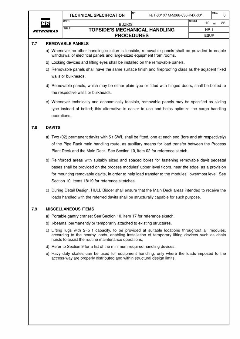
7.8 DAVITS
a) Two (02) permanent davits with 5 t SWL shall be fitted, one at each end (fore and aft respectively)
of the Pipe Rack main handling route, as auxiliary means for load transfer between the Process
Plant Deck and the Main Deck. See Section 10, item 02 for reference sketch.
b) Reinforced areas with suitably sized and spaced bores for fastening removable davit pedestal
bases shall be provided on the process modules’ upper level floors, near the edge, as a provision
for mounting removable davits, in order to help load transfer to the modules’ lowermost level. See
Section 10, items 18/19 for reference sketches.
c) During Detail Design, HULL Bidder shall ensure that the Main Deck areas intended to receive the
loads handled with the referred davits shall be structurally capable for such purpose.
7.9 MISCELLANEOUS ITEMS
a) Portable gantry cranes: See Section 10, item 17 for reference sketch.
b) I-beams, permanently or temporarily attached to existing structures.
c) Lifting lugs with 2~5 t capacity, to be provided at suitable locations throughout all modules, according to the nearby loads, enabling installation of temporary lifting devices such as chain hoists to assist the routine maintenance operations;
d) Refer to Section 9 for a list of the minimum required handling devices.
e) Havy duty skates can be used for equipment handling, only where the loads imposed to the access-way are properly distributed and within structural design limits.
TECHNICAL SPECIFICATION Nº:
I-ET-3010.1M-5266-630-P4X-001 REV.
0
UNIT:
BUZIOS SHEET
13 of 22
TITLE: TOPSIDE'S MECHANICAL HANDLING PROCEDURES
NP-1
ESUP
8 HANDLING DUTIES
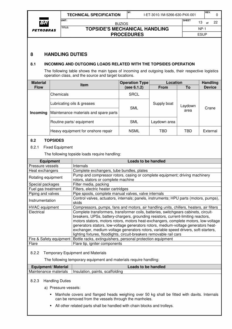
8.1 INCOMING AND OUTGOING LOADS RELATED WITH THE TOPSIDES OPERATION
The following table shows the main types of incoming and outgoing loads, their respective logistics operation class, and the source and target locations.
Material Flow
Item Operation Type
(see 6.1.2)
Location Handling Device From To
Incoming
Chemicals SRCL
Supply boat Laydown
area Crane
Lubricating oils & greases SML
Maintenance materials and spare parts
Routine parts/ equipment SML Laydown area
Heavy equipment for onshore repair NSML TBD TBD External
8.2 TOPSIDES
8.2.1 Fixed Equipment
The following topside loads require handling:
Equipment Loads to be handled
Pressure vessels Internals Heat exchangers Complete exchangers, tube bundles, plates
Rotating equipment Pump and compressor rotors, casing or complete equipment; driving machinery rotors, stators or complete machine
Special packages Filter media, packing Fuel gas treatment Filters, electric heater cartridges Piping and valves Pipe spools, complete manual valves, valve internals
Instrumentation Control valves, actuators, internals; panels, instruments; HPU parts (motors, pumps), skids
HVAC equipment Compressors, pumps, fans and motors, air handling units, chillers, heaters, air filters Electrical Complete transformers, transformer coils, batteries, switchgears cabinets, circuit-
breakers, UPSs, battery-chargers, grounding resistors, current-limiting reactors, motors stators, motors rotors, motors heat-exchangers, complete motors, low-voltage generators stators, low-voltage generators rotors, medium-voltage generators heat-exchanger, medium-voltage generators rotors, variable speed drivers, soft-starters, lighting fixtures, floodlights, circuit-breakers removable rail cars
Fire & Safety equipment Bottle racks, extinguishers, personal protection equipment Flare Flare tip, igniter components
8.2.2 Temporary Equipment and Materials
The following temporary equipment and materials require handling:
Equipment/ Material Loads to be handled
Maintenance materials Insulation, paints, scaffolding
8.2.3 Handling Duties
a) Pressure vessels:
� Manhole covers and flanged heads weighing over 50 kg shall be fitted with davits. Internals can be removed from the vessels through the manholes.
� All other related parts shall be handled with chain blocks and trolleys.

TECHNICAL SPECIFICATION Nº:
I-ET-3010.1M-5266-630-P4X-001 REV.
0
UNIT:
BUZIOS SHEET
14 of 22
TITLE: TOPSIDE'S MECHANICAL HANDLING PROCEDURES
NP-1
ESUP
� Means shall be provided to enable withdrawal, handling and reinstallation of the oil dehydrators’ transformers, located on top of the vessels, and also for maintenance of the vessels’ electrodes.
b) Heat exchangers:
� Tubular heat exchangers related with the gas compression systems are fixed tubesheet type, therefore only chemical cleaning and routine checking or small repairs can be performed in place. Any other maintenance duties require removal of the complete equipment for transfer to a shore-based workshop.
� Handling means are provided on all modules where fixed tubesheet exchangers are installed, such as monorails and trolleys with hoists. These exchangers are subsequently lifted with the offshore crane, for direct transfer to the supply boat.
� For shell and tube heat exchangers with removable bundles, monorails shall be provided for bundle handling and removal from exchanger shell. Space in front of channel cover shall be reserved for withdrawal of heat exchanger bundle. Pull posts shall be installed as material handling aid for bundle extraction, whenever required.
� For printed circuit type heat exchangers (PCHE), maintenance can be considered locally. In an event of equipment removal during breakdown maintenance, direct crane lifting of PCHE from module upper deck shall be primarily considered.
� For plate and frame heat exchangers, manual handling of plates an tie-bolts is considered and perfomed locally.
c) Rotating equipment:
� As far as possible, heavyweight parts or components of rotating equipment that require handling have been arranged within the reach of the deck crane.
� On modules where it was not feasible to satisfy this condition, loads weighing up to 5 t are transferred to the deck trolley using the skid and/ or module built-in resources, and parts heavier than 5 t are transferred to the diesel deck troller, aided by slings attached to padeyes or beam clamps on structural beams, temporary I-beams and/ or A-frames combined with chain blocks, or equivalent means.
d) Electrical equipment (HOLD):
Heavyweight electrical items, especially those installed inside the A&EM (M-17), have a low probability of requiring handling throughout the FPSO service life; in case this occurs, the following shall be considered:
� A&EM is outfitted with removable side panels to enable removal of large sized loads.
� On main power transformers, the coils are the parts subject to repair or replacement. Coils are lifted using monorails (fitted along the structural beams) and temporary hoisting and handling arrangements, for displacement to a location close to a removable side panel.
� VSDs are to be split into their main components, i.e. transformer panels and rectifier cell panels, before removal using the available monorails with trolleys and hoists.
� Other electrical items having lower weight but a higher probability of being serviced or replaced – such as circuit-breakers, UPS components, etc. – are manually disassembled and removed from the A&EM using manual trucks, which pass through the normal maintenance routes and access doors. Electrical panel columns are handled through the removable side panel of the transformers room.
� Use of monorails shall be considered for handling of electrostatic transformers during maintenance activities.
� Additionally, necessary means shall be provided for the draining, temporary storage and disposal of used oil from the electrostatic treater transformers. For accessing drain nozzles on the transformers and bushing housing, adequate space shall be provided around the transformer.
e) Instrumentation:
TECHNICAL SPECIFICATION Nº:
I-ET-3010.1M-5266-630-P4X-001 REV.
0
UNIT:
BUZIOS SHEET
15 of 22
TITLE: TOPSIDE'S MECHANICAL HANDLING PROCEDURES
NP-1
ESUP
� A&C panels are removed from the A&EM uppermost level through the removable panel of the adjacent HVAC Room.
� Heavy parts such as control valves and actuators are handled using chain hoists attached to beam trolleys or padeyes.
� On areas where no fixed structure is available above the valves, portable tripods or portable gantry cranes are used to hoist the parts and place them on carts or trolleys for transfer to the target location (ex.: maintenance area, workshop or laydown area).
� For the removal of heavy and/ or large sized valves, the adjacent pipe spools and actuator shall be previously disconnected from the valve body.
f) Pipe Spools:
� Removable spools shall be as short and light as possible, with 2 m maximum length and 0.5 t maximum weight.
� Scaffolding arrangements, portable gantry cranes or tripods can be used to support spool pieces. Alternative facilities such as davits, lifting lugs, pad eyes etc. can be provided above pipe spools, located on the nearby steel structure, in order to enable spool handling by means of hoists.
g) HVAC Equipment:
� Fans, electric motors, heaters, dampers, filter bags and other parts can be handled manually or using the mechanical devices provided by each packager, then transferred to carts and brought to the reach of the crane using the appropriate means, according to their original location.
h) Fire Fighting and Safety Equipment:
� CO2 cylinders are manually handled and placed into transportation cabinets (see item 9). Cylinders located in areas outside of the crane’s reach are displaced using hand trucks or trolleys, to an area within the crane reach.
� Fire extinguishers, portable safety devices and personal protection equipment can be manually handled and transported using hand trolleys.
i) Flare Tip:
� Flare package supplier shall provide a dedicated lifting device on top of the flare tip to assist its
replacement/ maintenance.
j) General items:
Insulation materials, paints, tools, scaffolding materials and similar goods are manually handled
and/ or transported using hand trolleys or the diesel-hydraulic deck trolley alongside the pipe rack
main handling route.
k) Lubricating Oil Handling and Storage:
� Oil for the T/G and compressor packages will be delivered to the FPSO in portable tanks and
may be temporarily stored on the laydown area.
� For the T/G, oil tanks can be directly placed on the modules storage area using the aft crane.
� For the gas compression packages, tanks arriving from the supply boat are picked with the
fore crane and placed on the respective modules or temporarily stored on the one of the
laydown areas provided by the HULL Contractor.
l) Mole Sieve Absorbent Media:
TECHNICAL SPECIFICATION Nº:
I-ET-3010.1M-5266-630-P4X-001 REV.
0
UNIT:
BUZIOS SHEET
16 of 22
TITLE: TOPSIDE'S MECHANICAL HANDLING PROCEDURES
NP-1
ESUP
� Use of deck cranes for the transport of absorbent media during loading activities of mole sieve
vessels shall be considered during the design.
� Laydown area above piperack may be considered as a temporary holding area for
loading/unloading equipment and absotrbetn media.
8.3 MAIN DECK
8.3.1 The following materials and equipment related with Topsides operation require handling within the
main deck and tanks area: pumps and electric motors, valves and actuators, pipe spools, spare parts
and consumables for maintenance and repair.
8.3.2 Handling duties: equipment underneath the topsides deck shall be handled using chain blocks, either
temporary ones fixed to padeyes or running on beam trolleys. Whenever feasible, loads shall be
transferred to a location within the reach of deck cranes, or else displaced along the maintenance
routes using pallet trucks, hydraulic stacker, hand trolleys or the diesel-hydraulic deck trolley.
8.3.3 It shall be verified during Detail Design, that the areas on the Main Deck intended for loads
displacement are structurally capable to withstand the involved loads.

TECHNICAL SPECIFICATION Nº:
I-ET-3010.1M-5266-630-P4X-001 REV.
0
UNIT:
BUZIOS SHEET
17 of 22
TITLE: TOPSIDE'S MECHANICAL HANDLING PROCEDURES
NP-1
ESUP
9 HANDLING AND LIFTING DEVICES
9.1.1 The following table shows a preliminary list of the required handling and lifting devices:
Item Device Reference Sketch SWL Qty. Purpose
01 Diesel-Hydraulic Self-Propelled Deck Trolley
5 t 1
Load handling at the Process Plant Deck
and Main Deck levels
22 t 1
02 Davit
5 t hold
Transfer of loads at the fore and aft ends of the Main Handling
Route, between Process Plant and Main Deck levels
03 Beam Trolley
TBD TBD Maintenance

TECHNICAL SPECIFICATION Nº:
I-ET-3010.1M-5266-630-P4X-001 REV.
0
UNIT:
BUZIOS SHEET
18 of 22
TITLE: TOPSIDE'S MECHANICAL HANDLING PROCEDURES
NP-1
ESUP
Item Device Reference Sketch SWL Qty. Purpose
04 Manual Chain
Hoist
TBD TBD Maintenance
05 Chain Operated
Beam Trolley
TBD TBD Maintenance
06 Pneumatic Chain Hoist
TBD TBD
Maintenance
(To be defined during Detail Design,
whenever deemed economically more
convenient than electric-driven
equipment suitable for operation in hazardous
zones)
07 Heavy Duty
Manual Chain Hoist
TBD TBD Maintenance
08 Electric Driven
Cable Hoist
22 t TBD Transfer of heavy
maintenance loads

TECHNICAL SPECIFICATION Nº:
I-ET-3010.1M-5266-630-P4X-001 REV.
0
UNIT:
BUZIOS SHEET
19 of 22
TITLE: TOPSIDE'S MECHANICAL HANDLING PROCEDURES
NP-1
ESUP
Item Device Reference Sketch SWL Qty. Purpose
09 Cylinder
Transport Cabinet
1 t hold Cylinder handling using the cranes
10 Beam Clamp
5 t hold General use
11 Shifting Skate
1 t hold General use
12 Heavy Duty
Skate
10 t hold General use
12 Lift table
0.5 t hold General use,
maintenance tasks
TECHNICAL SPECIFICATION Nº:
I-ET-3010.1M-5266-630-P4X-001 REV.
0
UNIT:
BUZIOS SHEET
20 of 22
TITLE: TOPSIDE'S MECHANICAL HANDLING PROCEDURES
NP-1
ESUP
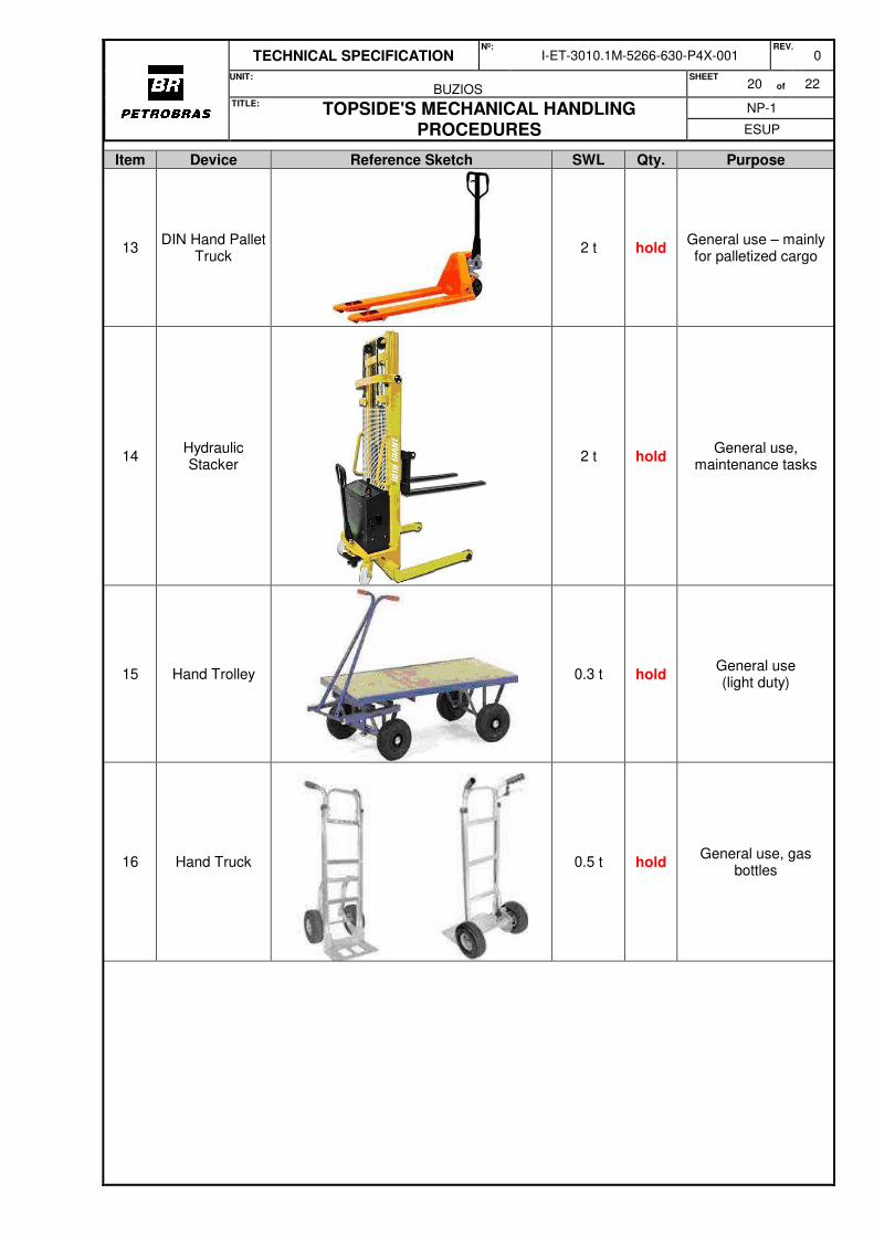
Item Device Reference Sketch SWL Qty. Purpose
13 DIN Hand Pallet
Truck
2 t hold General use – mainly for palletized cargo
14 Hydraulic Stacker
2 t hold General use,
maintenance tasks
15 Hand Trolley
0.3 t hold General use (light duty)
16 Hand Truck
0.5 t hold General use, gas
bottles

TECHNICAL SPECIFICATION Nº:
I-ET-3010.1M-5266-630-P4X-001 REV.
0
UNIT:
BUZIOS SHEET
21 of 22
TITLE: TOPSIDE'S MECHANICAL HANDLING PROCEDURES
NP-1
ESUP
Item Device Reference Sketch SWL Qty. Purpose
17 Portable Gantry
Crane (2 m span)
5 t hold Maintenance tasks
18 Pedestal for
Portable Davit
1 t hold
Top Level of Process Modules
2 t hold
19 Portable Davit
0.5 t hold
Top Level of Process Modules
1 t hold
2 t hold
20 Portable Tripod
3 t hold
General use; dismantling of valves and pipe spools on
decks with no structure above the
loads
21 Manual Cable
Puller
1.6 t hold General use
TECHNICAL SPECIFICATION Nº:
I-ET-3010.1M-5266-630-P4X-001 REV.
0
UNIT:
BUZIOS SHEET
22 of 22
TITLE: TOPSIDE'S MECHANICAL HANDLING PROCEDURES
NP-1
ESUP
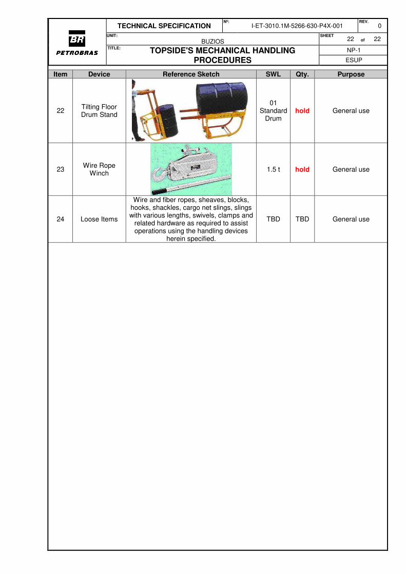
Item Device Reference Sketch SWL Qty. Purpose
22 Tilting Floor Drum Stand
01 Standard
Drum hold General use
23 Wire Rope
Winch
1.5 t hold General use
24 Loose Items
Wire and fiber ropes, sheaves, blocks, hooks, shackles, cargo net slings, slings with various lengths, swivels, clamps and
related hardware as required to assist operations using the handling devices
herein specified.
TBD TBD General use
Top Related