


Languages
Pages
Legal


WOLF‘S PLUMBOB NEWS 2009 Issue 12 Dec. 1, 2009
INCLINATION INDICATOR IN WELL HOLES
Author: Wolf Ruecker www.plumbbob.de
[email protected] - 183 -
PLUMB BOB AS INCLINATION INDICATOR IN WELL HOLES
Table of Contents
A INTRODUCTION: ............................................................................................................................ 183
B PATENTS.......................................................................................................................................... 184 B 1 US 802071 W. R. BAWDEN 1905 CLINOMETER ....................................................................... 184
B 2 US 1738589 E. KOPPL 1929 INCLINATION INDICATOR ......................................................... 186 B 3 US 2139899 Frank L. BUS 1938 DEPTH MEASURING DEVICE ................................................ 187
B 4 US 1895615 W. ELLIOT 1933 CROOKED HOLE INDICATOR .................................................. 188 B 5 US 2057787 D. B. MONROE 1936 OIL WELL SURVEYING INSTRUMENT ............................ 189
B 6 US 1980529 HUNSUCKER 1934 ORIENTING DEVICE FOR CORE DRILLS ........................... 190 B 7 US 1665058 G. D. HANNA 1928 DATA IN EARTH BORES ....................................................... 191
B 8 US 1905299 McLAUGHLIN 1933 RECORDING INCLINATION................................................ 192 B 9 US 1905546 WEBSTER 1930 RECORDING INCLINATION ....................................................... 192
C CONCLUSION .................................................................................................................................. 193
A INTRODUCTION: Dear Reader, Fellow Collector,
recently there was offered on ebay a (not complete)
DIETZGEN CLINOMETER for a BORE HOLE, marked
“No. 12 CHAS GARVEY DIAMOND DRILLING CO
GROWN POINT NY PATENT APPLIED FOR”
There I had the idea to search for (patented) plumb bobs
used for this task.
On the paper in the box of the instrument we read:
!!! Use of CANDY !?
(Sweets or crystallization?)
It looks very similar to the patent US 802071 W. R.
BAWDEN 1905 (more see B 1)
COMPASS PENDULUM

[email protected] - 184 - WOLF'S PLUMB BOB NEWS 2009-12 inclination indicator in well holes
Very interesting for me is, how they get the information
from the inclinometer (plumb bob).
There are different ways:
- Warm gelatin gets cold
- Candy
- Ball indicator with markings thereon (imprinter)
- Point with barbs
- A spring presses a recording disc
- Water presses the plumb bob down
- and so on
B PATENTS I found the following PATENTS
B 1 US 802071 W. R. BAWDEN 1905 CLINOMETER William Reynold Bawden was a citizen of the Commonwealth of Australia
This patent is similar (but not identically) to the pictures shown on page 1. Let’s look how it works:
(Text form the patent)
“The object of my improved clinometers is to provide an instrument which will easily and accurately record
the position and angle of bore-holes whether vertical or horizontal and at any point of locality in their line
of travel.
As is well known in mining operations, the diamond drill has a tendency to deviate from its desired or
assumed line of travel by reason of pursuing the line of least resistance or other causes and which errors
and consequent loss are the greater in hard and refractory country.

[email protected] - 185 - WOLF'S PLUMB BOB NEWS 2009-12 inclination indicator in well holes
This clinometers has been principally designed to record such errors, so that the travel of a diamond drill
and consequent position of the bore may from time to time be checked and charted in order to ascertain the
position of the lode or other desired object as quickly and as cheaply as possible. ….
… A further advantage consists that when the clinometers is used for surveying a vertical or inclined bore-
hole and upon the gelatin becoming firmly set the instrument may be placed in a horizontal position, thus
giving a clear view of the magnetic needle, and, again, if found necessary, the compass-box may be removed
from its gimbal and placed on the reading-protractor, with the object of bringing the needle as nearly as
possible to the sighting-line. …
… When in use, this box b2 is filled with gelatin, and upon the cooling of same it will concurrently act and
fix the needle b in the position it occupies at such moment of time. ….
… The method for the use of the instrument is as follows:
The pendulum-case e and compass-box b2 are both filled with warm gelatin or other similar transparent
liquid and which acts as the medium for setting the pendulums d and d1 and the magnetic needle b. The
instrument is then placed within its primary case f, and for the better maintenance of the gelatin in a liquid
form, if found likely to congeal owing to its small bulk, hot water or hot gelatin may be poured into the
space inclosed by the primary case f, causing the instruments to be held in a warm bath, and such water or
gelatin would be removed prior to the reading of the results. The outer protector-tube g2, containing the
instruments, is lowered or placed in that locality of the bore-hole which is to be charted. The instrument
there remains until such time as the recording gelatin has set hard, and thereby setting the needle b and
the pendulums d and d1 in the positions which they
occupy at such moment of congealment. In the use
of the instrument due care should be taken so that
the gelatin or other medium, owing to variations
of temperature in the bore-hole, does not
respectively congeal or liquefy prior to or
subsequent to the time of the taking of the record.
When the instrument is withdrawn from the bore-
hole, the readings of the pendulums and compass
may be made with greater or more precise
accuracy by removing and placing each separately
on a reading-protractor made specially for such
purpose. “

[email protected] - 186 - WOLF'S PLUMB BOB NEWS 2009-12 inclination indicator in well holes
B 2 US 1738589 E. KOPPL 1929 INCLINATION INDICATOR
This 80 years old patent shows
another System:
“Fig. 1 shows a well hole which
is inclined to the vertical, a
portion thereof being broken
away, and an inclinometer for
insertion in a small hole at the
bottom.
Fig. 2 is a longitudinal section
through the inclinometer shown
in Fig. 1 on an enlarged scale
with the indicator released.
Fig. 4 and 5 are plan views of
the ball indicator with markings
thereon. …
… In the body is a chamber 41
for a pendulum or plumb bob.
… The lower end of bore 55 is
reduced in diameter and sloped
to form a seat for a ball 56. This
ball is preferably of soft metal
adaptable to receive an imprint
from the imprinter projection 49. The socket member and ball form a swivel,
there being a rod or line 57 attached thereto, so that the ball will be caused to
swing with the line. This line may be of comparatively rigid material. …
Attached to the plumb line is a bob 58. …
The rotary drill pipe or drill string 14 is then forced downwardly and
cause the lug 26 on body 21 to enter the bore 45 in the cap and project
the socket member 52, thereby releasing the ball 56 and permitting it to
be moved by the plumb line as shown in Fig. 2. … As the drill string is
raised, the lug 26 is retracted, permitting the socket member to retract
and clamp the ball 56. This causes an indentation on the ball, such as
62a or 62
b Figs. 4 and 5. … The mark on the ball 56 will indicate the
inclination. …
The plumb bob will have been clamped in vertical alignment. The drill
string is the forced downwardly to shear the pin and cause the lug to
release the plumb bob ball. This will cause the plumb bob to swing to
vertical position. Upon raising the drill string,
the ball will again be clamped and marked to
indicate the inclination of the well hole with
respect to the vertical. … “
[email protected] - 187 - WOLF'S PLUMB BOB NEWS 2009-12 inclination indicator in well holes
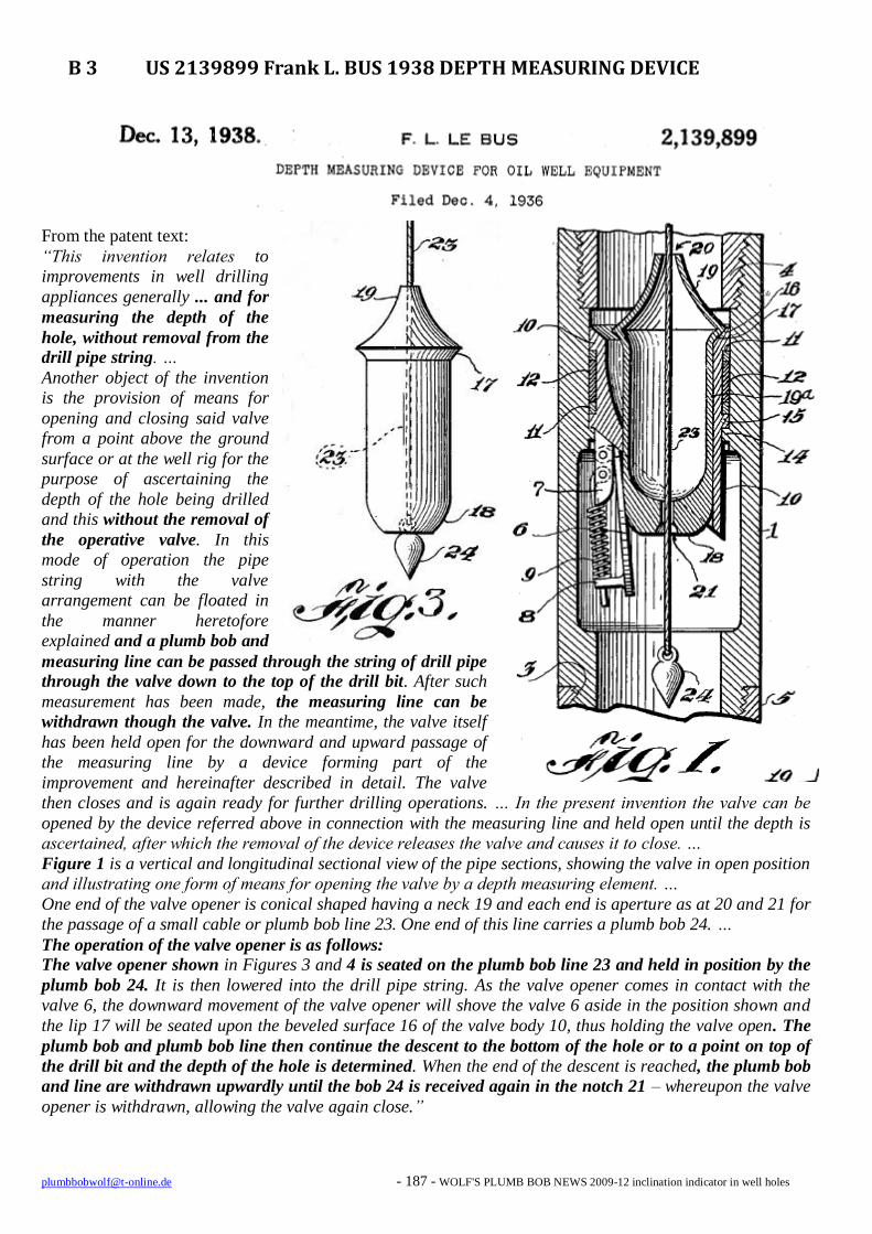
B 3 US 2139899 Frank L. BUS 1938 DEPTH MEASURING DEVICE
From the patent text:
“This invention relates to
improvements in well drilling
appliances generally ... and for
measuring the depth of the
hole, without removal from the
drill pipe string. …
Another object of the invention
is the provision of means for
opening and closing said valve
from a point above the ground
surface or at the well rig for the
purpose of ascertaining the
depth of the hole being drilled
and this without the removal of
the operative valve. In this
mode of operation the pipe
string with the valve
arrangement can be floated in
the manner heretofore
explained and a plumb bob and
measuring line can be passed through the string of drill pipe
through the valve down to the top of the drill bit. After such
measurement has been made, the measuring line can be
withdrawn though the valve. In the meantime, the valve itself
has been held open for the downward and upward passage of
the measuring line by a device forming part of the
improvement and hereinafter described in detail. The valve
then closes and is again ready for further drilling operations. … In the present invention the valve can be
opened by the device referred above in connection with the measuring line and held open until the depth is
ascertained, after which the removal of the device releases the valve and causes it to close. …
Figure 1 is a vertical and longitudinal sectional view of the pipe sections, showing the valve in open position
and illustrating one form of means for opening the valve by a depth measuring element. …
One end of the valve opener is conical shaped having a neck 19 and each end is aperture as at 20 and 21 for
the passage of a small cable or plumb bob line 23. One end of this line carries a plumb bob 24. …
The operation of the valve opener is as follows:
The valve opener shown in Figures 3 and 4 is seated on the plumb bob line 23 and held in position by the
plumb bob 24. It is then lowered into the drill pipe string. As the valve opener comes in contact with the
valve 6, the downward movement of the valve opener will shove the valve 6 aside in the position shown and
the lip 17 will be seated upon the beveled surface 16 of the valve body 10, thus holding the valve open. The
plumb bob and plumb bob line then continue the descent to the bottom of the hole or to a point on top of
the drill bit and the depth of the hole is determined. When the end of the descent is reached, the plumb bob
and line are withdrawn upwardly until the bob 24 is received again in the notch 21 – whereupon the valve
opener is withdrawn, allowing the valve again close.”

[email protected] - 188 - WOLF'S PLUMB BOB NEWS 2009-12 inclination indicator in well holes
B 4 US 1895615 W. ELLIOT 1933 CROOKED HOLE INDICATOR
From the patent text:
“This invention relates to indicating apparatus to be used by well
drillers. It should be distinguished from apparatus such as has been
used for surveying a well after it is drilled to indicate the inclination or
“dip” of the well at different points in its depth. …
Figure 1 is a vertical section through the device and showing a short
portion of a drillstring in which the device is placed. This view shows
the indicating apparatus in its normal position.
Figure 2 shows the apparatus in an inclined position such as it would
have in a crooked portion of a hole being drilled, and illustrates the
apparatus in its “set” or actuated position. …
Any device of this nature can be employed, but for simplicity I prefer
to employ a plumb-bob, which is mounted in such a way that it
constantly maintains itself with its axis in a substantially vertical
position. This directional device is mounted in the casing of the device
in such a way that it can cooperate with an indicating member.
Normally the directional device or plumb-bob is out of contact with
the indicating member, but adjacent to it. In the normal position of
the devise, when the hole is straight, the plumb-bob is in a position
such that its axis coincides with the axis of the tool string and with the
central axis of the indicating member. If the hole being drilled starts to
deviate the axis of the tool string and the casing of the instrument will
become inclined, but the plumb-bob will maintain itself with its axis
vertical. When the parts are in this relation, I develop a relative
movement between the indicating member and the plumb-bob which
brings them together, thereby forming an indication, or mark, by the
plumb-bob on the indicating member. This mark will be off the center of the indicating member, and the
number of degrees that it is off from the center will indicate the
inclination of the crooked portion of the hole. If the device is
constructed so as to operate as indicated above, the indicating member
is formed of some yielded material which can be punched or marked
by the point of the plumb.bob when it strikes it. For this purpose I
might employ a plate of soft material such as lead or any other
suitable material.
If desired, the instrument may include means for holding the plumb-
bob in its position of contact with the indicating member, in which
case, if desired, the indicating member need not be constructed of a yielded material, but could be formed of
any material which would operate to engage the point of the plumb-bob and hold it in a relatively fixed
position. For this purpose I might employ a punctural diaphragm of any suitable material, or a diaphragm
of wire gauze of fine mesh.
The contact between the plumb-bob and the indicating member or element can be accomplished in any
desired way, for example, by a down-jar of the instrument such as would cause the point of the plumb-bob to
strike the indicating element.”

[email protected] - 189 - WOLF'S PLUMB BOB NEWS 2009-12 inclination indicator in well holes
B 5 US 2057787 D. B. MONROE 1936 OIL WELL SURVEYING INSTRUMENT
From the patent text:
“This invention relates to a surveying instrument for oil wells, and has for its principal object the provision of a
highly efficient device which can be lowered into a well
casing or drill stem to produce an accurate record of the
vertical inclination of said well. … Fig. 2 is an enlarged vertical section through the operating
portion of the device illustrating the latter in the “released”
position. … Fig. 4 is an enlarged detail plan view of the indicating
target….
Fig. 7 is an enlarged vertical detail section through the
plumb bob employed in the invention.
Fig. 8 is a detail horizontal enlarged section through the
plumb bob bearing. …
A bearing block 16 is supported in the upper portion of the inner housing 11 upon a suitable shoulder ring 51 and
supports ball bearings 17 which in turn support a weighted
plumb bob 18. The plumb bob 18 depends from a bearing ball 19 which rests on the ball bearings 17. The bearings
17 and the ball 19 are covered and protected by a suitable
bearing cap 20.
The plumb bob 18 contains a needle 21 having an
accurately ground point which projects from the bottom of
the plumb bob. This point swings immediately above an
indicating target card 22 which is removably carried on the upper extremity of a combined compass sleeve and target
support 23.
It is desired to call particular attention to the construction of the plumb bob 18, and its supporting bearing. The bob
consists of a central tube 40 about which is secured the
weighted plumb bob proper 18. The latter is conical in
shape with its smaller extremity downward. The lower extremity of the tube 40 projects from the bob and is also
tapered to a relatively pointed extremity. The upper
extremity of the tube 40 projects above the bob and is threaded to be received in a
threaded socket 41, upon an extension of which, the bearing ball 19 is formed. The
needle 21 extends entirely through the length of the tube 40, and contacts at its
upper extremity with the bottom of the inverted socket 41.A spring 42 constantly forces the needle upwardly. When the device is not in use, the tube 40 can be threaded downwardly in the socket 41 so as to bring its lower extremity
over the needle point to protect the latter. When being set for use, the tube 40 is threaded into the socket 41 to allow
the needle point to project the desired distance.
It has been found that a more accurate swing of the plumb bob results if the ball bearings 17 are separated by means
of smaller balls 43, as shown in Fig. 8. Only the large balls contact with the bearing ball 19.
The indicating target consists of a cardboard disc marked in degrees of compass direction
around its periphery and marked in degrees of inclination by a series of concentric numbered circles as shown in Fig 4. The cards are held upon a diaphragm surface 46 and are clamped
in place thereon by means of a clamping ring 47. The upper surface of the clamping ring 47 is
marked with degree marks as indicated by the lines and dots in Fig. 4.”

[email protected] - 190 - WOLF'S PLUMB BOB NEWS 2009-12 inclination indicator in well holes
B 6 US 1980529 HUNSUCKER 1934 ORIENTING DEVICE FOR CORE DRILLS
From the patent text:
“… Aside from the question of coring and the
determination of geological structure, it is frequently
advantageous to know whether or not the drill hole is
being maintained in a substantially vertical line, or if
the drill hole is “wandering” and, if so, to what
extent and in what direction. Thus, it could be readily
determined by accurately mapping a drill hole
whether or not the well was maintaining its course
within the property on which it was “spudded
in”. …
The general construction of my invention comprises
a compass, which is provided with a device for
clamping the needle, and a plumb bob which is
adapted to be suspended above a soft material by
means which may be adjusted for automatic release
of the plumb bob simultaneously with the clamping
of the mentioned compass. The release of the plumb
bob permits the same to fall in a vertical line and to
be imbedded in the mentioned soft material. It will
be apparent that by knowing the center of the soft
materials and its distance from the point of
suspension of the plumb bob, the inclination of the
core barrel at the time the plumb bob was released
may be readily calculated by measuring the distance
from the center of the soft material to the point at
which the falling plumb bob strikes the same, and
that the accuracy of this measurement may be
regulated by varying the vertical distance between
the point of suspension and the center point of the
mentioned soft material. …
The plumb bob 63 is preferably provided with an
extending penetrating point 64, which may optionally
be provides with a plurality of barbs, indicated at 64´,
which are adapted to engage the gauze 55´ and hold
the plumb bob against movement after the point has
been imbedded in the soft material. …
An interval timing device or suitable clock mechanism
indicated at 90 is mounted upon the lower bas member
15 by means of the standards 90´ and is adapted to
impart a segmental rotation to the plumb bob releasing trigger 73 and the
compass clamping trigger 39 through the lateral movement of a secondary
flexible member 91 which is received by the eye 82 in the arm 81 upon the plumb
bob releasing trigger.”
COMPASS

[email protected] - 191 - WOLF'S PLUMB BOB NEWS 2009-12 inclination indicator in well holes
B 7 US 1665058 G. D. HANNA 1928 DATA IN EARTH BORES
From the patent text:
“Fig. 2 represents an enlarged vertical sectional view
of the recording mechanism of the invention.
… This embodiment of the invention is carried out by combining with suitable test drilling apparatus of the
present day type, a compass, either magnetic or
gyroscopic, a plumb-bob and setting mechanism for the compass and plumb-bob. The purpose of the compass is
to indicate the direction of the slope of the strata
beneath the earth’s surface in order that a definite compass point, such as the north point, may be
established in the bore and on the sample or core. The
plumb-bob is arranged so that it will indicate the
inclination of the bore relative to the vertical. The
compass and plumb-bob will also provide for
determining the direction of the inclination of the bore
and the angle of inclination of the test core removed from the earth. Operatively associated with the compass is a means which automatically locks the
compass needle at a predetermined time following the cessation of the drilling operation
and before the breaking off of the test core, thereby recording the direction of the slope of the strata so that accurate data may be obtained. There is also provide a means which
will automatically fix the plumb-bob in the position in which it hangs, immediately
following the drilling operation and before breaking off of the test core, which means
may operate co-incidentally with the compass locking means but not necessarily so, the main requirement being that it operate following the cessation of the drilling operation.
Various means for locking the plumb-bob and compass needle at the proper time may be
employed but I prefer to use an automatically operated mechanism which is set into
operation by the rotation of the drill and continues to operate after the rotation of the
drill ceases, due to the momentum thereof, this continued operation bringing about the
locking of the compass needle and plumb-bob at a predetermined time, say from 20 to
30 seconds after the drill rotation ceases, thereby allowing the compass needle to come to position of rest or quiet. This likewise permits the plumb-bob to come to a steady
hanging position before it is locked in the indicating position and in this way accuracy is assured. …
… In addition to the compass I mount within the capsule a plumb-bob 12, which in the present instance depends from the compass. The plumb-bob is of the ordinary type except that it is provided with a long, sharp point 13. The
compass and plumb-bob are preferably mounted in the upper part of the capsule so that the mechanism which is
associated therewith may be effectively disposed below them. The compass needle 14 is adapted to be held against movement or locked by means of a locking rod 15 which extends through the compass casing 16 and is adapted to be
moved into and out of engagement with the compass needle. The plumb-bob is adapted to be locked or held by means
of a reticulated disk 17 preferably made of fine mesh wire screen and which is adapted to be moved into and out of
engagement with the pointed end 13 of the bob. … … The said rod is moved downward against the action of the spring by the double cam 24 engaging the projection 25.
The plumb-bob locking member 17 is vertically adjustably mounted upon the rod 15 by means of a collar and set
screw arrangement shown at 28. … “

[email protected] - 192 - WOLF'S PLUMB BOB NEWS 2009-12 inclination indicator in well holes
B 8 US 1905299 McLAUGHLIN 1933 RECORDING INCLINATION
From the patent text:
“This invention relates to an instrument for recording the inclination of the drill pipe
in the drilling of oil wells …
… Suitable mounted upon plunger 31 is a recording disc 34 of suitable material such
as wood, a soft white metal or brass, on which are scribed circles so that the degree
from the vertical may be read. …
... The pumps are then stopped to allow piston 22 to return to its initial position, to
again permit spring 33 to force plunger 31 and disc 84 into recording engagement
with plumb-bob 18. … As soon as the pumps are started plunger 22 is again forced
downward and through the mechanism already described forces the recording disc
away from bob 18.”
B 9 US 1905546 WEBSTER 1930 RECORDING INCLINATION
From the patent text:
To withdraw the drill pipe requires considerable time and labor
and is, therefore, expensive and consequently the drill pipe is run
as long as possible before being withdrawn and it is, therefore, a
further object of this invention to provide an instrument which may
be actuated any number of times to check the inclination of the
drill pipe during a sing run of the drill pipe. …
It is a further object of this invention to provide an instrument
having a sealed plumb-bob chamber. …
Figure 2 is a partial view of Figure 1 but illustrating the plumb-
bob in engagement with the recording disc. …
The lower end of shell is screw threaded to receive a removable
plug 16 which is made pressure tight by means of gasket 17 and
thus there is formed a fluid tight chamber 18 in which a plumb-
bob 19 is pivotally mounted upon gimbal rings 20 and 21. … The
use of gimbal rings for pivotally mounting a plumb-bob so that the
plumb-bob may swing freely about the pivot is well known that
further explanation of this feature I deemed unnecessary.
A target or recording disassembly 25 may be made of any suitable
material such as wood or soft metal or as illustrated, of a paper
target 26 mounted upon a cork disc 27 which in turn may be
mounted upon a taget plug 28. The paper target 26 may be
inscribed with concentric circles one degree apart.
The target or recording disc assembly 25 is resiliently held in engagement with the needle of bob 19 by
means of spring 29.”

[email protected] - 193 - WOLF'S PLUMB BOB NEWS 2009-12 inclination indicator in well holes
C CONCLUSION
In the drawings and patent texts above we see, that the plumb bob was used very often in instruments used
for earth bores. For the engineers it was of interest to know what inclination and direction the hole has.
The systems to find this information are very different.
I am surprised that very common plumb bobs were used in these instruments.
The period where I searched for patents was between 1900 and 1940
Of interest for me are the different systems to “write”/record the results, given by the plumb bob (and
compass needle). I am not sure that these systems gave very correct information.
Unfortunately I don’t know how this measurement is made in our days.
Who knows more about it?
Now we have ONE TRADE MORE that uses a plumb bob: the WELL DRILLING ENGINEER
The original text of the mentioned patents above you can see in the Google patent search:
http://www.google.com/advanced_patent_search
Remark:
This is an article of the monthly published WOLF’S PLUMB BOB NEWS that is sent on demand as PDF-file attachment by email.
You can see all former publications on the website www.plumbbob.de
Remarks and contact by email: [email protected]
The WOLF’S PLUMB BOB NEWS will be continued in 2010. (if you want to get it).
I wish you and your family
A MERRY
CHRISTMAS and
A HAPPY NEW YEAR
2010
Do we meet us on the
3rd
PLUMB BOB COLLECTORS MEETING
end of September 2010 in Cologne /Germany? Stay-plumb
Wolf
Top Related