


Languages
Pages
Legal


Improvements in VANET Simulator in NS-3
Master’s Project Final Report
Author: Bradley Dupont
Email: [email protected]
Project Advisor: Dr. Michele Weigle
Email: [email protected]
Project Presentation Date: November 11, 2011
Department of Computer Science
Old Dominion University
1

Acknowledgements1. Abstract2. Introduction3. Architecture
3.1 HighwayProject3.2 Highway
3.2.1 Physical Properties3.2.2 Highway Connection3.2.3 Vehicle Movement
3.2.3.1 Lane Changing3.2.3.2 Acceleration and Translation3.2.3.3 Movement and Connections
3.3 WifiConfiguration3.4 Vehicle/Traffic Light Generators
3.4.1 Vehicle Generator3.4.2 TrafficLightGenerator
3.5 Vehicle3.5.1 Model3.5.2 LaneChange
4. Customization4.1 Vehicle Control4.2 Creating Custom Vehicles4.2 Network Control
5. Verification of Functionality5.1 Comparison with Arbabi’s Code5.2 Omni-Directional Verification5.3 Verification Conclusion
6. ConclusionReferencesAppendix A - Expected vs Actual PlotsAppendix B - Source Code LocationAppendix C - Simple Highway Example
2
Acknowledgements
I would like to express my gratitude for Dr. Weigle for introducing me to the world
of VANET. A deep thank you also to Hadi Arbabi for creating the initial version of
the simulator in ns-3. Finally, I want to express my deep gratitude to the faculty of
the Computer Science department of ODU. Their wisdom and experience has been
instrumental in guiding me through my education.
3

1. Abstract
The vehicular ad-hoc network (VANET) community faces the difficulty that buying
and equipping vehicles with wireless networking devices is far too expensive to be
practical. Of course, simulation provides the solution. However, most simulators are
divided into either vehicle or network simulators. In most VANET simulations, the
vehicle traffic is pre-generated and the trace of the movement is fed into a network
simulator to determine the network properties of the VANET. While useful, this
technique does not allow vehicles to adjust behavior based on network messages.
Arbabi and Weigle implemented a vehicle simulator into the popular ns-3 networking
simulator mobility model [1]. While a step forward, the implementation was limited in
scope to a single two-directional highway with at most 5 lanes in both directions. We
have improved the model to allow for highways that point in any direction, connect to
other highways, and allow vehicles to turn left or right depending on desired destination.
Other improvements include XML-based configuration, separate code for generating
Vehicle instances, and basic traffic light functionality.
4

2. Introduction
Vehicular ad-hoc networks (VANETs) are an exciting and growing field of study.
There are many possibilities of using ad-hoc communication between vehicles for
information dissemination, safety, or even entertainment. These possibilities, driven in
the United States by the Department of Transportation Intellidrive initiative, have
launched many different lines of research. Due to the cost of vehicles and equipment,
almost all of this research has been done using simulation. However, the current group
of simulators publicly available either completely splits the vehicle and network stages
of the simulation or over-simplifies either the vehicle or networking simulation. Arbabi
and Weigle [1] implemented IDM and MOBIL lane change model [2] in ns-3. This
solved the problem of combining the two types of simulation and did so using a popular,
powerful, and accurate network simulator.
Arbabi's architecture centered around two classes: Highway and Vehicle.
Vehicles were fully-functional ns-3 nodes that contained additional information
regarding their current acceleration, velocity, and position. The Highway class was the
``brains'' and used Model and LaneChange objects attached to Vehicles to move
vehicles based on IDM and MOBIL. In addition, Highway used ns-3 callbacks to enable
simulation developers to take control of Vehicles based on network messages,
overriding, if need be, the standard controls used in Highways.
However, the implementation had several major limitations. The biggest limitation
lay in the fact that the Highway class provided could only run east-west and could not
5

create intersections. While this architecture covers many of the ``steady state'' VANET
situations on freeways, it could not deal with urban or suburban situations with roads
laid out in grids, requiring vehicles to stop and turn often. Another problem was that the
Highway class contained code not only for managing vehicle motion, but also for
Vehicle creation and network management. Though fairly well commented and written,
this made maintenance and customization difficult. Finally, all parameters were
controlled through command-line options. While acceptable for a simple setup, it would
not be scalable to anything even remotely complex.
To increase the capabilities of the simulator, several improvements were made.
The major improvement was that Highways could be pointed in any direction. This
removed the necessity for one instance of Highway to control both directions of a two
direction highway. Now, two instances could be created, one pointed in the opposite
direction of the other and separated by whatever median distance was required. The
second major improvement was to remove the vehicle generation and wireless control
from the Highway class. New methods were added to Highway to allow external
classes to modify the Vehicle instances inside of the Highway. The final major
improvement was to store almost all of the configuration of a simulation in an XML
document. This allows complex simulations to be set up once and re-used by others.
This paper will discuss the various classes upgraded and introduced during the
code upgrade. It will then compare the results obtained from Arbabi's simulation versus
the new implementation to show that IDM and MOBIL implementations are unchanged,
merely modified to be omni-directional.
6
3. Architecture
3.1 HighwayProject
Arbabi's architecture's primary container was Highway. This has been replaced
by the HighwayProject class. The HighwayProject class’s primary duty is to process the
XML document representing the Highway configuration, wiring together the instances of
the various classes, and then starting and running the simulation. The classes directly
controlled by HighwayProject are: Highway (section 3.2), WifiConfiguration (section
3.3), VehicleGenerator (section 3.4.1), and TrafficLightGenerator (section 3.4.2).
HighwayProject first reads in an XML document from the file system using the
TinyXml library [3]. See Appendix B for source code information. An XSD document
describing the XML is available along with the source code. Using this information, it
first creates all of the Highway instances. It then ``wires'' them together, connecting
Highways to each other based on the configuration. See section 3.2.2 for more details
on the connections. Once these connections are made, HighwayProject uses Dijkstra's
algorithm to creating a routing map for each Highway instance to all other Highway
instances (if reachable). After the algorithm is run, each Highway has a map containing
an entry for all other Highways that will direct a vehicle to either turn left, turn right, or go
straight.
Once the Highways are created and routed, HighwayProject creates all
instances of WifiConfiguration and VehicleGenerator. Each VehicleGenerator is
7

connected to one Highway. A single WifiConfiguration can be associated with multiple
VehicleGenerators. If different WifiConfigurations are wanted for different generators,
however, they can be configured and used separately.
HighwayProject is also responsible for creating two trace files, one for vehicle
location and one for network traffic. The default locations are ``vehicleTrace.csv'' and
``networkTrace.csv'' in the working directory of the program. Other file names/locations
can be provided to HighwayProject before starting. The vehicle trace has the following
columns: Simulation Time (Nanoseconds), Vehicle ID (Integer), Type ID (0 for Vehicle,
1 for Obstacle, 2 for traffic light), X Position (double), Y Position (double), Direction
(double), Velocity (double), Acceleration (double). The network trace has the following
columns: Simulation Time (Nanoseconds), Vehicle ID (Integer), Message (String), User
Index (an integer based on the type of message). The network trace, by default, does
not print any messages. Each type of message (i.e. Physical Receipt OK, Physical
Receipt Error, Vehicle Receipt, etc.) must be turned on independently.
3.2 Highway
Highway is the primary container for Vehicle (section 3.5) instances. It does not
create any Vehicle instances on its own. Instead, it only manages the Vehicles it
contains at the time of the current step.
8

3.2.1 Physical Properties
A Highway is always straight. It has the following characteristics: Name Description
Start Location The center point of the start of the Highway
Length The length of the highway in meters (default 1000m)
Number of Lanes
The number of lanes the highway has (default 1)
Lane Width The width of each lane (default 5m)
Direction The direction a vehicle will travel on the Highway (default 0 radians off the x axis)
Each lane has an ID, beginning with 1 in the leftmost lane. The leftmost lane is
determined based on Direction. Lanes always terminate on a line parallel to the Y axis
located at a point in the middle of the Highway, Length way from the start of the
Highway. If the Direction is either or (straight up or straight down), the terminating
line is parallel to the X axis instead of the Y axis.
3.2.2 Highway Connection
A Highway has four different types of connections to other Highways: Left, Right,
Straight, and Back. When a connection is established, two indexes are sent in, an
initializing offset, and a lane offset. The initializing offset determines what lane in the
current Highway the connecting Highway will start at. This initializing offset is
determined from the leftmost lane, with the first offset being 0 up to (Number of Lanes
9
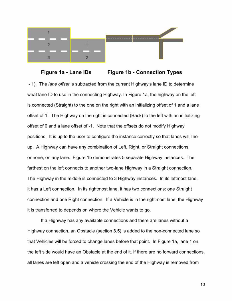
Figure 1a - Lane IDs Figure 1b - Connection Types
- 1). The lane offset is subtracted from the current Highway's lane ID to determine
what lane ID to use in the connecting Highway. In Figure 1a, the highway on the left
is connected (Straight) to the one on the right with an initializing offset of 1 and a lane
offset of 1. The Highway on the right is connected (Back) to the left with an initializing
offset of 0 and a lane offset of -1. Note that the offsets do not modify Highway
positions. It is up to the user to configure the instance correctly so that lanes will line
up. A Highway can have any combination of Left, Right, or Straight connections,
or none, on any lane. Figure 1b demonstrates 5 separate Highway instances. The
farthest on the left connects to another two-lane Highway in a Straight connection.
The Highway in the middle is connected to 3 Highway instances. In its leftmost lane,
it has a Left connection. In its rightmost lane, it has two connections: one Straight
connection and one Right connection. If a Vehicle is in the rightmost lane, the Highway
it is transferred to depends on where the Vehicle wants to go.
If a Highway has any available connections and there are lanes without a
Highway connection, an Obstacle (section 3.5) is added to the non-connected lane so
that Vehicles will be forced to change lanes before that point. In Figure 1a, lane 1 on
the left side would have an Obstacle at the end of it. If there are no forward connections,
all lanes are left open and a vehicle crossing the end of the Highway is removed from
10

the simulation. In Figure 1a, the right Highway instance would have no Obstacles and
Vehicles would be removed from the simulation upon leaving.
3.2.3 Vehicle Movement
Each step of the simulation, HighwayProject calls the step function on all
Highway instances. Once the Highways are done with the individual translations,
HighwayProject then goes through all Highway instances again, telling them to move
Vehicles to their connecting Highways as necessary. This is needed to make sure that
Vehicles are not moved twice.
3.2.3.1 Lane Changing
Every tenth step, a Highway will attempt lane change calculations. Every Vehicle
(but not Obstacles or TrafficLights) has a LaneChange object associated with it. See
section 3.5.1 and 3.5.2 for more information on the LaneChange and the MOBIL model.
All lane change calculations are done before any acceleration or translation
calculations. This is to make sure that Vehicle accelerations and translations are not
affected by a Vehicle being in two places at once.
It is during this step that a Vehicle’s destination is queried. This destination is
looked up in the Highway’s routing map. The result in the map will be either Straight,
Left, or Right. If a Vehicle is going Straight, the Highway instance will make sure that
the Vehicle does not attempt to change lanes into a “turn only” lane. If the Highway
only has Left or Right connections, the Vehicle will default to turning Right. If the
Vehicle needs to make a turn, the Highway will (safely) force the Vehicle to get into a
11

lane that has a connection of the proper direction. If there are multiple turn lanes, the
Highway will force it only to the first turn lane. Once a Vehicle is in a turning lane, it can
change lanes normally, provided that the lane it is changing to is also a turning lane.
3.2.3.2 Acceleration and Translation
During each step, a Vehicle’s Model object is queried to determine what its
current acceleration is. The Model object implements the Intelligent Driver Model (IDM).
For more information, see section 3.5.1. During this calculation, if the value returned
from the Model is the special value NaN, Highway assumes that the Vehicle wants to
pass through the Vehicle object in front of it. This currently only happens in the case of
a TrafficLight being place too close in front of the Vehicle for it to safely stop. What this
allows the Highway to do is effectively model the “yellow light” scenario.
When a Vehicle is making a turn, the Highway will adjust the Vehicle’s speed to a
configured parameter (either turn left speed or turn right speed). This adjustment is
done by linearly decreasing the desired speed of the Vehicle from its usual desired
speed to the configured parameter over the length of the highway (Figure 2). Once the
Vehicle has made the turn, its desired speed is returned to normal and the IDM takes
12

over. Note that the desired speed is adjusted, not actual speed. All accelerations are
determined by the IDM.
3.2.3.3 Movement and Connections
During translations and lane changes, it is necessary to have the distance to
both Vehicle instances in front and behind the current Vehicle. The Highway provides
all of these calculations. It first checks its own Vehicle lists for the appropriate Vehicles.
If it can’t find a Vehicle, it looks at its connecting Highways. If there are no appropriate
Vehicles in the adjacent Highway, that Highway will continue the search recursively until
their are no available connections in that lane. Only Straight connections are queried.
Querying only Straight connections is due to the fact that Vehicles travelling straight do
not want to base their accelerations on Vehicles that have already turned.
3.3 WifiConfiguration
The purpose of the WifiConfiguration class is to encapsulate wifi parameters.
These parameters will usually be the same for the entire simulation. By putting this
information in a separate class, multiple VehicleGenerators can reference the same wifi
configuration without having to be individually configured. The table below lists all of
the parameters available for configuration:
Name Description
Wifi Standard The wifi standard used (see ns-3 documentation for a complete listing of strings available). Default is “WIFI_PHY_STANDARD_80211a”
13

Name Description
Data Mode The data mode used by this node (see ns-3 documentation for a complete listing of strings available). Default is “OfdmRate6MbpsBW10MHz”
TX Power Start / End The power (in decibels) for the transmissions start and end.
TX Power Levels The number of power levels. Default is 1.
TX/RX Gain The gain for transmission / receipt respectively. Default 2.0.
Energy Detection Threshold
The lowest energy that can be detected. Default is -101.0 decibels.
3.4 Vehicle/Traffic Light Generators
Vehicle instances can be created by one of three different methods. Either a
Vehicle can be created by custom code, a VehicleGenerator, or a TrafficLightGenerator.
3.4.1 Vehicle Generator
The VehicleGenerator is the primary source of Vehicles in the simulator. In
Arbabi’s code, this functionality was contained in the Highway class. However, this
made Highway too complicated both to maintain and configure. VehicleGenerators
operate independently of HighwayProject and its Highways. HighwayProject creates
them and configures them based on the XML document supplied. However, when the
simulation is started, HighwayProject calls the initialize function on VehicleGenerator
and does nothing further.
The only constructor available to VehicleGenerator passes in a Highway instance
14

to associate with it. The VehicleGenerator uses the Highway to determine how often it
should evaluate. During each evaluation, the VehicleGenerator increments a counter
with a randomly determined value. When this value reaches a configured limit, the
VehicleGenerator will attempt to insert a new Vehicle. If there is a Vehicle in the lane
that the VehicleGenerator is attempting to inject into, the VehicleGenerator will wait until
the Vehicle is at least a (configured) minimum distance from the start of the Highway.
During the wait time, the VehicleGenerator continues to increment the counter.
The parameters available for configuration are listed in the table below:
Name Description
Flow This attribute describes how many vehicles/sec the Vehicle generator creates. If set directly, there is no randomization involved.
RV Flow This is an ns3 RandomVariable. It is used on each step to get a value to apply to a sum. Once it reaches the value of flow, the VehicleGenerator is ready to insert a Vehicle. Setting flow initializes this value to a variable that will return a constant value that will insert vehicles at precisely flow per second.
Low/High Velocity These two attributes set the range for a uniform variable that determines a Vehicle’s desired speed. Low velocity is used as the Vehicles starting speed.
RV Velocity This can be set to replace the default variable used by setting Low/High velocity. Note that Low velocity must be set first, as that is the value used for the Vehicles starting speed.
Penetration Rate The percentage of Vehicles that will have Wifi equipped to them
Truck Probability The VehicleGenerator creates two types of Vehicles, trucks and sedans. Truck Probability determines what probability it is of the next Vehicle being a truck.
15

Name Description
Minimum Gap The minimum distance a Vehicle has to be in the Highway before another Vehicle can be injected.
Destination Map A map of cumulative values determining where the Vehicle will want to go when it is created. I.e., if there are three Highways (1,2,3), if there is a 30% chance a Vehicle will want to go to 1 or 2, and a 40% chance the Vehicle will want to go to 3, the map will have the values {0.3,1; 0.6,2; 1.0,3]
In addition to these configuration parameters, various network helpers can be
installed to the VehicleGenerator. These helper classes (provided by ns-3) are used to
prepare a Vehicle’s wifi. Usually, however, these helper classes will be pulled from a
WifiConfiguration object and assigned by the HighwayProject class.
3.4.2 TrafficLightGenerator
The TrafficLightGenerator class creates a special kind of Vehicle that has a type
of “Traffic Light.” As mentioned in the Highway section (section 3.2.3.2), Traffic Lights
are treated slightly differently from regular Obstacles in that it is possible to drive
through them. The TrafficLightGenerator has three timing parameters: Straight, Left,
and Buffer. Straight is the amount of time the Highway is opened up for traffic going
Straight or Right. Left is the amount of time any left turn lanes are opened for traffic.
Buffer is the amount of time that all lanes are blocked to allow for any Vehicles in the
intersection to finish travelling.
The TrafficLightGenerator class can be supplied with up to four Highway
instances. Each of these is configured with the following options:
16

Name Description
Side An enumeration for either Top, Bottom, Left or Right. Top and Bottom are controlled together, as are Left and Right.
Distance The distance into the Highway the traffic lights are placed
List of Left Lanes A list of all of the lanes that are left turn lanes.
The TrafficLightGenerator operates on time schedules determined by its own
configuration and not by any consideration for Highway step times. In this way, it
operates similarly to VehicleGenerator, except that VehicleGenerator takes the
simulation step size into account during its scheduling.
3.5 Vehicle
Vehicles are the primary atom of the simulator. They represent either a travelling
Vehicle, an Obstacle, or a TrafficLight. Vehicles are also fully functional ns-3 nodes. If
equipped, they will communicate over a wifi channel. The Vehicle contains the
following physical characteristics:
Name Description
Lane The current lane the Vehicle is travelling in
Length The length of the Vehicle
Width The width of the Vehicle
Velocity The current speed of the vehicle in meters per second
Acceleration The current acceleration of the vehicle in meters per second per second
Direction The current direction of the Vehicle in radians off of the positive X axis
17

In addition to the Wifi and Physical parameters, the Vehicle also has a stack of
destination IDs. During each step, a Highway will check this stack to determine if the
Vehicle wants to move Left, Right, or Straight. When a Vehicle is added to a Highway,
the Highway will check the stack against its own ID. If the IDs match, the Highway
informs the Vehicle and the destination stack is popped. If there are no more
destinations available, the Vehicle will return the value -100000.
3.5.1 Model
Each Vehicle also has a Model object associated with it. This Model contains the
implementation of the IDM. It can be customized based on desired velocity, maximum
acceleration and braking, the minimum gap it wants to maintain, and the minimum time
headway it wants to maintain. During each step, the Highway passes information to the
Model about the Vehicle in front and the Model determines what the current
acceleration should be.
3.5.2 LaneChange
In addition to the Model class, each Vehicle also has a LaneChange object. The
LaneChange object can be configured with a politeness factor, a changing threshold, a
minimum gap, a maximum braking, and a right bias. The calculation takes into account
the Vehicles current desired speed, its current speed, the distance to the Vehicle in
front of itself, the distance to the Vehicle in the lane to be changed to, and the effect a
lane change would have on the acceleration of the Vehicle behind the current Vehicle in
18

the next lane. A calculation is made based on changes in Acceleration by all Vehicles
involved. This is combined with a lane bias and a politeness factor. After all of these
factors are included, if the value is above the threshold, the Vehicle will announce that it
is ready to change lanes.
19

4. Customization
4.1 Vehicle Control
All Highway classes check a vehicle control callback on each iteration. A
callback is an ns-3 object that functions similarly to a function pointer, except with more
functionality. In order to use the callback, it is necessary to create a callback and pass
it to HighwayProject. HighwayProject then assigns the callback to all of the Highway
instances configured to it. The function should return true if the Vehicle’s movement
data is being modified.
4.2 Creating Custom Vehicles
Creating a custom Vehicle instance can be done at any time. A function call can
be scheduled into the ns-3 Simulator, and the Vehicle created in that function. It can
then be inserted into any Highway configured and it will be managed like any other
Vehicle. No special code is needed.
4.2 Network Control
By default, no Vehicle will send any messages. Vehicle does have some utility
functions for using its attached wifi node to send packets, especially to the broadcast
address. It is recommended that if it is desired that all Vehicles should broadcast
20

packets of some kind, the messages should be created and managed by the Vehicle
Control callback.
21

Figure 3 - Difference from Arbabi’s Version
5. Verification of Functionality
It is desired to demonstrate that the new code has at least the same functionality
as the original code. In order to demonstrate this, a one-direction, two-lane Highway
will be created in both versions of the code and the locations of Vehicles fed into the
simulation compared. To verify that the omni-directional nature of the new code is also
functioning as expected, the same Highway will be pointed in multiple directions to
show that the Vehicle location is as expected.
5.1 Comparison with Arbabi’s Code
In order to verify that the two simulators operate in the same way, a simulation
scenario was set up that would insure that a vehicle would experience acceleration,
22

Figure 4 - Expected vs. Actual Examples
deceleration, and lane changing. The same simulation was run on both environments
and the data from each compared. The results for the comparison are summarized
in Figure 3. As easily visible from the plot, the results are identical between the two
simulators.
5.2 Omni-Directional Verification
The next step is to verify that the results hold regardless of the direction the
Highway is configured to point. The same scenario was used with the Highway pointed
in the following directions: 45, 90, 135, 180, 225, 270, and 315 degrees. The expected
values were calculated based on the vehicle travelling at 0 degrees. The actual values
obtained from simulation were then subtracted from the calculated values. Figure 4 is a
sampling and is typical of the two kinds of plots. For a complete listing of plots, see
Appendix A. From the 45 degree plot, it can be seen that the error seems to cluster
around the 0 axis. For the 90 degree plot, the values are exactly 0 for most of the
simulation with a few anomalous spikes. In both cases, the error is both minimal and
seems to correct itself over time. This is due to the fact that the simulation calculates
23

position changes as increases from the beginning of the Highway, not as increases
from the current Vehicle position. This means that errors will remain small (usually
within rounding error) and will not propagate as the simulation continues. The small
errors at the beginning of the simulation that increase as the simulation reaches a
critical point is probably caused by the increase of the absolute value of the location
over time (magnifying the effect of rounding errors).
5.3 Verification Conclusion
By combining the results from these two tests, it can be reasonably assumed that
the IDM and MOBIL implementations have been successfully transformed from uni-
direction to omni-directional. In addition, the rounding errors caused by moving at
angles other than the axis have been successfully mitigated by having the translation
calculations done from a fixed starting point rather than relative to current Vehicle
location.
24

6. Conclusion
A good VANET simulator is required to have both an excellent networking
simulator and a good approximation of vehicle traffic. Arbabi’s implementation of a
simulator using ns-3’s mobility model and IDM and MOBIL was a great step forward.
Ns-3’s excellent network simulation was combined with a fairly accurate and intelligent
driver model. However, the simulator was limited in capability. It could only operate in
one direction and did not allow for combinations of Highways. This project updated the
code to add the following functionality: omni-directional Highways, connected Highways,
separated Vehicle generation to a separate class, basic traffic light functionality, and
xml-based configuration. This was done without sacrificing the accuracy of IDM and
MOBIL.
25

References
1. Arbabi, H., and Weigle, M. 2010. Highway Mobility and Vehicular Ad-Hoc Networks in NS-3, In Proceedings of the 2010 Winter Simulation Conferance 2. Treiber, M., and D. Helbing. 2002. Realistische Mikrosimulation von Straßenverkehr mit einem einfachen Modell , In Proceedings of the 16th Symposium Simulationstechnik (ASIM 2002), 514—520. 3. Thomason 2011 TinyXml library <http://www.grinninglizard.com/tinyxml/> Visited October 24, 2011
26

Appendix A - Expected vs Actual Plots
27

Appendix B - Source Code LocationSource code is managed on google code. The project name is ns-3-highway-mobility.
The URL for the source code browser is: :http://code.google.com/p/ns-3-highway-mobility/
source/browse/. To check out the source code you’ll need mercurial and a google account.
The instructions for checking out the code are availabe at http://code.google.com/p/ns-3-
highway-mobility/source/checkout. The code is divided into two branches. The “trunk” branch
contains the updated code described in this paper. Under the “branches” folder, the “version 1”
code contains the simulator as implemented by Arbabi.
28

Appendix C - Simple Highway Example
The code described below is available as part of the source code download. A much
more complicated example is included in the source code which creates a four-way
intersection. That XML file includes connections and TrafficLightGenerators. The
source-code for running it remains the same.
The first step is to create an XML document. Below is a simple example for a straight
highway with Wifi configured and attached to a VehicleGenerator.
The root node contains how long the simulation will run and what the step size is.
While “numberOfRuns” is defined in the XML, it is not currently used by HighwayProject.
The “highways” root contains one or more “highway” nodes. For more details on
what the attributes mean, see section 3.2.1. The next section is “wifiConfigurations”
29

and stores all of the wifi configuration instances. The “wifiConfigId” is only used to
join “wifiConfiguration” instances to “vehicleGenerator” instances and is not available in
the code. The last node is the “vehicleGenerators” node. It links to a Highway instance.
The second step is to create a main instance that will use this XML file.
This section of the code is responsible for creating and parsing the command line
parameters. Once they have been loaded, the XML document is loaded and passed
into the utility bean HighwayProjectXml. That class and its children contain all
configuration (and can be created by hand if desired).
30

This next section creates the HighwayProject instance and passes the XML
configuration into it. It pulls the location for the vehicle and network trace and passes
those in. Finally, depending on the boolean flags, the code enables various kinds of
traces.
This section accomplishes some customization hooks. Note that “project.getHighways()
” returns a map of highwayId (from the XML) to Ptr<Highway>. The
Simulator::Schedule demonstrates how to schedule a function to be called by the
simulator. The next line also shows how to establish a callback. The definition
of “addCustomVehicle” and “controlVehicle” are displayed below.
31

This section of code demonstrates how to create a Vehicle instance and adding to a
Highway instance. Note that the line “temp->SetPosition” is not strictly required. The
function “AddVehicleToBeginning” sets the Vehicle position already.
32

This is a control vehicle callback function. This is called on every single Vehicle for
every single Highway configured. The counter is used to make sure that messages
are not flooded. There seems to be an error if messages are sent from the Vehicle
too soon. If the counter limit is set to 0 (msgCounter == 0), ns-3 sends an error. The
function always returns false because the Vehicle acceleration and position data is not
modified.
33
Top Related