


Languages
Pages
Legal

iii
SIMULATION OF WCDMA RADIO OVER FIBER TECHNOLOGY
SITI HARLIZA BINTI MOHD RAZALI
A project report submitted in partial fulfillment of the
Requirements for an award of the degree of
Master of Engineering (Electrical-Electronics and Telecommunication)
Faculty of Electrical Engineering
Universiti Teknologi Malaysia
APRIL 2007

v
Dedicated to my loving husband & family, ABG HAKIM & MAMA,
ANGAH, NINI, AISHAH and my adorable baby HAZIQ.

vi
ACKNOWLEDGEMENT
Alhamdulillah, I am greatly indebted to ALLAH SWT on His blessing for
making this study successfully.
I would like to express my gratitude to honorable Dr. Razali Bin Ngah, my
supervisor, for his guidance, support and encouragement throughout my study. I am
also thank you to my colleagues for providing an enjoyable study environment at UTM.
Finally, I would like to thank my husband and my mum, angah, nini and aishah
for their full support and patience. For my baby, I hope to make up for all the lost time
that we have not spent together.

vii
ABSTRACT
The demand for broadband services has driven research on millimetre wave
frequency band communications for wireless access network due to its spectrum
availability, and compact size of radio frequency devices. However, the mm-wave
signals suffer from severe loss along the transmission as well as atmospheric
attenuation. In other words, upcoming wireless networks will use a combination of air-
interface methods in different channels and in different cells that can be changed
dynamically to meet variations in traffic conditions. One of the solution to overcome
these problem is by using low-attenuation, electromagnetic interference-free optical
fiber. Radio over Fiber (RoF) is integration of optical fiber for radio signal transmission
within network infrastructures that is considered to be cost-effective, practical and
relatively flexible system configuration for long-haul transport of millimetric frequency
band wireless signals. This project is about to simulate WCDMA Radio Over Fiber
using Matlab Simulink. By doing so, the efficiency can be measured by the performance
of BER (Bit Error Rate). The finding of this project is the WCDMA RoF is suite with
3G and 4G application along with increasing users every year whole the world. The
conclusion is the simulation of WCDMA RoF was success developed throughout
objective.

viii
ABSTRAK
Permintaan yang semakin tinggi dalam perkhidmatan jalur lebar telah membuka
ruang para penyelidik untuk mengkaji dan menyelidik dalam bidang komunikasi jalur
frekuensi gelombang milimeter untuk rangkaian penyampai tanpa wayar yang
bergantung pada ketersediaan spektrum dan saiz kompak sesuatu alat radio frekuensi
itu. Walau bagaimanapun, isyarat gelombang milimeter ini terancam kepada gangguan
sepanjang proses penghantarannya seperti gangguan atmosfera. Dengan kata lain,
perkembangan rangkaian tanpa wayar menggunakan kombinasi kaedah ruang
hubungkait udara dalam saluran yang berlainan dan sel-sel yang berlainan yang boleh
berubah secara dinamik untuk variasi penyesuaian dalam kondisi bebanan. Antara jalan
penyelesaian untuk mengatasi masalah tersebut ialah menggunakan pengecilan yang
rendah, gentian optik bebas gangguan elektromagnetik. Isyarat radio menggunakan
gentian diintegrasikan dari gentian optik untuk penghantaran isyarat radio dalam
rangkaian infrastruktur yang mempertimbangkan kos-efektif, praktikal dan sistem
konfigurasi fleksibel secara relatif untuk penghantaran jarak jauh isyarat jalur frekuensi
tanpa wayar. Projek ini berkisar dengan simulasi WCDMA isyarat radio dalam gentian
menggunakan perisian Matlab Simulink. Dengan itu, keberkesanannya boleh diukur
melalui kadar kesalahan bit (BER) yang diperolehi dari simulasi tersebut. Projek ini
menemukan penggunaan WCDMA isyarat radio dalam gentian ini sangat sesuai
digunakan bagi pembangunan sistem 3G dan 4G dengan pertambahan pengguna setiap
tahun di seluruh dunia. Kesimpulannya, simulasi ini berjaya dibangunkan mengikut
objektif projek.
ix
TABLE OF CONTENTS
CHAPTER TITLE PAGE
DECLARATION iv
DEDICATION v
ACKNOWLEDGEMENT vi
ABSTRACT vii
ABSTRAK viii
TABLE OF CONTENTS ix
LIST OF TABLES xiii
LIST OF FIGURES xiv
LIST OF ABBREVIATIONS xvi
1 INTRODUCTION
1.1 Introduction 1
1.2 Objective of Study 3
1.3 Scope of Project 4
1.4 Research Methodology 5
1.5 Thesis Outline 7

x
2 RADIO OVER FIBER
2.1 Introduction 8
2.2 What Is RoF? 8
2.3 The Radio Over Fiber Technology 11
2.4 Radio Over Fiber System 12
2.5 Radio Over Fiber Concept 13
2.6 Advantages Of Using RoF In Mobile Communication Networks 15
2.7 Benefits of Radio over Fiber Systems 16
2.7.1 Low Attenuation Loss 16
2.7.2 Large Bandwidth 17
2.7.3 Immunity to Radio Frequency Interference 18
2.7.4 Easy Installation and Maintenance 19
2.7.5 Reduced Power Consumption 19
2.7.6 Operational Flexibility 20
2.7.7 Millimeter Waves 21
2.7.7.1 Advantages of mm-waves 21
2.7.7.2 Disadvantages of mm-waves 21
2.7.8 Radio System Functionalities 22
2.8 Applications of Radio over Fiber Technology 22
2.8.1 Cellular Networks 23
2.8.2 Satellite Communications 23
2.8.3 Video Distribution Systems 24
2.8.4 Mobile Broadband Services 24
2.8.5 Wireless LANs 25
2.8.6 Vehicle Communication and Control 26
2.9 Summary 26

xi
3 WIDEBAND CODE DIVISION MULTIPLE ACCESS (WCDMA)
3.1 Introduction 27
3.2 RoF Using WCDMA 27
3.3 Parameters Of WCDMA 32
3.4 WCDMA Overview 35
3.4.1 Direct-Sequence CDMA 35
3.4.2 Wideband 36
3.4.3 Synchronization Aspects 36
3.4.4 Modes of Operation 37
3.5 Basic WCDMA Transmission Technologies 42
3.6 Characteristics Of WCDMA (Technical) 42
3.6.1 Highly Efficient Frequency Usage 42
3.6.2 Freedom From Frequency Administration 43
3.6.3 Low Mobile Station Transmit Power 43
3.6.4 Resources Used Independently in Uplink and Downlink 44
3.7 The Wideband Properties Of WCDMA Allow Higher Efficiency
In The Following Aspects 44
3.7.1 Wide Range of Data Speeds 44
3.7.2 Improved Multipath Resolution 45
3.7.3 Statistical Multiplexing Effect 45
3.7.4 Reduced Intermittent Reception Rate 45
3.8 Summary 46
xii
4 SIMULATIONS
4.1 Introduction 47
4.2 Simulations 47
4.2.1 BPSK Modulation 48
4.2.2 QPSK Modulation 49
4.2.3 QPSK Modulation using RoF 51
4.3 Results and Discussion 52
4.3.1 BPSK vs QPSK 56
4.3.2 RoF with different of Fiber Length 57
4.4 Summary 60
5 CONCLUSION AND SUGGESTIONS
5.1 Conclusion 61
5.2 Suggestion For Future Research 62
REFERENCES 64

xiii
LIST OF TABLES
TABLE TITLE PAGE
3.1 Parameter of WCDMA 33
3.2 Comparison of 2G and 3G CDMA Systems 34
xiv
LIST OF FIGURES
FIGURE TITLE PAGE
1.1 Research methodology flow chart 5
2.1 Typical layout of a bidirectional analog optical link using direct
modulation of laser diodes 11
2.2 Radio over Fiber Concept 12
2.3 Optically fed remote antenna network for microcellular RoF
systems 14
3.1 The basic techniques of the Direct Sequence Spread Spectrum 38
3.2 Principles of DS-CDMA 40
3.3 Allocation of bandwidth in WCDMA in the
time-frequency-code space 41
3.4 Spreading and dispreading in DS-CDMA 41
4.1 Constellation Diagram for BPSK 48
4.2 Block simulink for BPSK Modulation 49
4.3 Constellation Diagram for QPSK 50
4.4 Block simulink for QPSK Modulation 50
4.5 Block simulink for WCDMA using RoF 51
4.6 Theoretical BER performance with AWGN channel 52
4.7 BER performance with AWGN channel for BPSK 53
4.8 BER performance with AWGN channel for QPSK 54
4.9 Comparison BER of BPSK and QPSK 55
4.10 Comparison BER of BPSK, QPSK and Theory 56

xv
4.11 BER performance for fiber length 0.2 km 57
4.12 BER performance for fiber length 1 km 58
4.13 BER performance for fiber length 48 km 59
4.14 Comparison BER between 0.2 km, 1 km and 48 km 59
xvi
LIST OF ABBREVIATIONS
AWGN Additive White Gaussian Noise
BER Bit Error Rate
BPSK Binary Phase Shift Keying
BS Base Stations
DWDM Dense Wavelength Division Multiplex
EDFA Erbium Doped Fiber Amplifier
FDD Frequency Division Duplex
GMSK Gaussian Minimum Shift Keying
GSM Global System for Mobile Communications
IF Intermediate Frequencies
IMDD Intensity Modulation and Direct Detection
ITS Intelligent Transport Systems
IVC Inter-Vehicle Communication
LAN Local Area Network
MBS Mobile Broadband System
MS Mobile Station
MVDS Multipoint Video Distribution Services
OFDM Orthogonal Frequency Division Multiplexing
OTDM Optical Time Division Multiplexing
POF Polymer Optical Fiber
PSK Phase Shift Keying
QAM Quadrature Amplitude Modulation
QPSK Quadrature Phase Shift Keying
xvii
RAP Radio Access Point
RF Radio Frequency
RFI Radio Frequency Interference
RHD Remote Heterodyning and Detection
RIN Relative Intensity Noise
RS Remote Station
ROF Radio Over Fiber
RVC Road-to-Vehicle Communication
SC Switching Centre
SMF Single Mode Fiber
TDD Time Division Duplex
UMTS Universal Mobile Telecommunication Systems
UTRA Universal Terrestrial Radio Access
WBMCS Wireless Broadband Mobile Communication Systems
WCDMA Wideband Code Division Multiple Access
CHAPTER 1
INTRODUCTION
1.1 Introduction
Radio over Fiber (RoF) application has attracted much attention recently because
of the increasing demand for capacity/coverage and the benefits it offers in terms of
low-cost base station deployment in macrocellular system. RoF systems are now being
used extensively for enhanced cellular coverage inside buildings such as office blocks,
shopping malls and airport terminal. RoF is fundamentally an analog transmission
system because it distributes the radio waveform, directly at the radio carrier frequency,
from a central unit to a Radio Access Point (RAP). Note that although this transmission
system is analog, the radio system itself may be digital such as GSM.
Mainstream optical fiber technology is digital. Telecommunication networks use
synchronous digital hierarchy transmission technology in their cores. Fiber-based data
networks such as fiber distributed data interface and gigabit Ethernet all use digital
transmission. Fiber transmission links to base stations in mobile communications
systems are digital. Digital optical fiber transmission links are therefore ubiquitous in
telecommunications and data communications, constituting a high volume market worth
billions of dollars worldwide.
2
Wideband Code Division Multiple Access (WCDMA), air interface can now is
regarded as a mature technology ready to provide the basis for the third generation
wireless personal communication systems, known as ‘Universal Mobile
Telecommunication Systems’ (UMTS). These systems will make extensive use of
microcells and picocells in order to deliver high bandwidth services to customers.
WCDMA also known as third generation systems. The systems are designed for
multimedia communication can be enhanced with high quality images and video and
access to information and services on public and private networks will be enhanced by
the higher data rates and new flexible communication capabilities of third generation
systems. This together with the continuing evolution of the second-generation systems
will create new business opportunities for manufacturers, operators and the providers of
content and applications using these networks.
In the standardization forum, WCDMA technology has emerged as the most
widely adopted third generation air interface. Its specification has been created in 3GPP
(the 3rd Generation Partnership Project), which is the joint standardization project of the
standardization bodies from Europe, Japan, Korea, the USA and China. Within 3GPP,
WCDMA is called UTRA (Universal Terrestrial Radio Access), FDD (Frequency
Division Duplex) and TDD (Time Division Duplex). The name of WCDMA being used
to cover both FDD and TDD operation.
The benefit of using RoF for WCDMA distributed antenna systems is expected
to be even more important, partly because of their higher frequency and bandwidth
requirements.
In this project, the simulation of WCDMA RoF using Matlab Simulink had
successful developed. In this simulation, the fiber was represented by gain and 3rd order
3
polynomial was represented laser diode. The complete simulink block successfully run
and get BER performance to rate it.
1.2 Objective of Study
Objective of this research is to simulate a WCDMA radio over fiber (RoF) for
microcellular mobile communication systems using Matlab Simulink.
To achieve this objective various simulink blocks are developed such as with
AWGN Channel, polynomial as laser diode and gain is present fiber using MATLAB
SIMULINK.
From the research, main cause of using RoF is to shift the system complexity
away from the remote base station antenna and toward centralized radio signal
processing installation. In a RoF link, laser light is modulated by a radio signal and
transported over an optical fiber medium. The laser modulation is analog since the
radio-frequency carrier signal is an analog signal. The modulation may occur at the
radio signal frequency or at some intermediate frequency if frequency conversion is
utilized.
The basic configuration of an analog fiber optic link consists of a bi-directional
interface containing the analog laser transmitter and photodiode receiver located at a
base station or remote antenna unit, paired with an analog laser transmitter and
photodiode receiver located at a radio processing unit. One or more optical fibers
connect the remote antenna unit to the central processing location.
4
1.3 Scope Of Project
The works undertaken in this project are limited to the following aspects:
i) Literature review.
Reviews on the WCDMA using RoF technology by specific parameters of
WCDMA .
ii) Modeling and simulation of the WCDMA downlink system with RoF using
suitable parameters for laser diode, fiber and photodiode.
iii) Perform a simulation works by using a MATLAB/Simulink to observe BER.
iv) Compare the performance of the normal AWGN channel and different length of
fiber by setting different value of gain that present fiber.
5
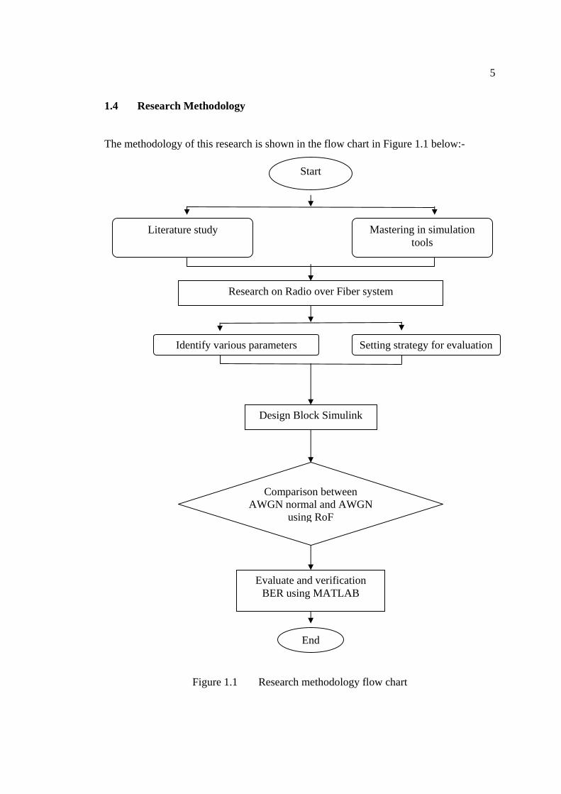
1.4 Research Methodology
The methodology of this research is shown in the flow chart in Figure 1.1 below:-
Figure 1.1 Research methodology flow chart
Start
Literature study Mastering in simulation tools
Research on Radio over Fiber system
Identify various parameters Setting strategy for evaluation
Design Block Simulink
End
Comparison between AWGN normal and AWGN
using RoF
Evaluate and verification BER using MATLAB

6
In the beginning, there are two tasks that need to be done simultaneously.
Besides of doing literature review, exercises and tutorials need to be done for mastering
the simulations tools and some preliminary simulations need to be carried out as well.
Then, the problem of this research will be stressed with radio over fiber system
that an alternative to increasing base station complexity is to move the complex portions
of the network to a central processing location where the number of expensive signal
processing elements can be reduced by greater sharing among users.
Thus, identify various parameters and set the strategy for evaluation that can be
used to develop the block simulink.
After the preliminary research, the design of block simulink are developed and
tested by several of parameters.
Then, comparison between normal case and new case is done to get the result.
All simulink is using MATLAB SIMULINK.
Finally, the proposed block simulink will be evaluated with BER (bit error rate)
to determine the performance.

7
1.5 Thesis Outline
The thesis is structured as follows. The Chapter 1 discusses the general
introduction of this project.
Chapter 2 outlines the project background of this project, which is including the
basic introduction of RoF (Radio over Fiber) and further knowledge about RoF and their
characteristics.
Chapter 3 outlines the literature review of this project that is introduce more to
WCDMA technologies and characteristics.
Chapter 4 contains simulation and result.
The conclusion of the results and recommendation for future works will be
presented in Chapter 5.
8
CHAPTER 2
RADIO OVER FIBER
2.1 Introduction
This chapter will inform further explanatory about radio over fiber. There will be
explanation about what is RoF, the technology, system and concept of RoF. The benefit
of radio over fiber also stated. Furthermore, there are also told the advantages using RoF
in the mobile communication networks and applications of using RoF.
2.2 What is RoF?
Upcoming wireless networks will use a combination of air-interface methods in
different channels and in different cells that can be changed dynamically to meet
variations in traffic conditions. The co-existence of access methods such as adaptive
TDMA, TD-CDMA and WCDMA in the network could employ software-radio
approaches in the implementation of the base stations, but this will increase the
complexity present at the base stations and may impact cost.

9
User terminals are projected to have varying capabilities in terms of data
transmission rates and modulation levels supported, but for reasons of mobility, power
consumption, and cost, the majority of user terminals will operate on a single air-
interface and limited number of transmission parameters at a given time. In this
scenario, most of the complexity resides in the base stations. However, placing the
complexity in the base stations may incur significant cost if the number of base stations
required for network deployment is large. An alternative to increasing base station
complexity is to move the complex portions of the network to a central processing
location where the number of expensive signal processing elements can be reduced by
greater sharing among users.
By using highly linear optical fiber links to distribute RF signals from a central
location to radio access points (RAPs) RoF allows the RAPs to be extremely simple
since they only need to contain optoelectronic conversion devices and amplifiers. All
communication functions such as coding, modulation and up conversion can be
performed at a central location. A simple RAP means small and light enclosures (easier
and more flexible installation) and low cost (in terms of equipment cost and
maintenance costs). Centralization results in equipment sharing, dynamic source
allocation and more effective management. All of this adds up to an access technology
that makes life easier and cheaper for operators.
Reasoning why RoF is able to shift system complexity away from the antenna is
that optical fiber is an excellent low-loss (0.2 dB/km optical loss at 1550 nm) and high-
bandwidth (50 THz) transmission medium. Transmission takes place at the radio carrier
frequency rather than the more conventional digital base band systems. The optical links
in RoF are therefore analog in nature, in that they reproduce the carrier waveform. The
radio carrier can be modulated with a digital modulation scheme such as GMSK (in
GSM) or QPSK (in UMTS).
10
In a RoF link, laser light is modulated by a radio signal and transported over an
optical fiber medium. The laser modulation is analog since the radio-frequency carrier
signal is an analog signal. The modulation may occur at the radio signal frequency or at
some intermediate frequency if frequency conversion is utilized. The basic configuration
of an analog fiber optic link consists of a bi-directional interface containing the analog
laser transmitter and photodiode receiver located at a base station or remote antenna
unit, paired with an analog laser transmitter and photodiode receiver located at a radio
processing unit. One or more optical fibers connect the remote antenna unit to the
central processing location.
Reduction in base station or remote antenna unit complexity is an attractive
outcome of using radio-over-fiber links. Reducing the remote base station complexity is
attractive because equipment, construction, and maintenance costs may be reduced.
Base station and remote antenna unit density can therefore be increased economically,
leading to lower power mobiles and higher bandwidth transmission. Increased wireless
and optical network integration is therefore seen as a plausible means of decreasing
costs in voice and data networks, while increasing network capacity.
The layout of a simple bi-directional directly modulated RoF link are shown in
Figure 2.1. In each direction the input RF signal is applied to a laser diode where it
modulates the intensity of the output light. In most cases this light will have a
wavelength of either 1300 or 1550 nm for low transmission loss in silica fiber. The fiber
may be multimode or single mode, although the latter is preferred for links spans of
more than a few tens of meters for a p-i-n photodiode, which provides an RF power
output proportional to the square of the input optical power. This type of optical link is
known as intensity modulated-direct detection (IM-DD). Other types of link are possible
involving frequency or phase modulation, but for cellular applications the IM-DD links
are used for reasons of simplicity and cost.

11
Figure 2.1 Typical layout of a bidirectional analog optical link using direct
modulation of laser diodes [1]
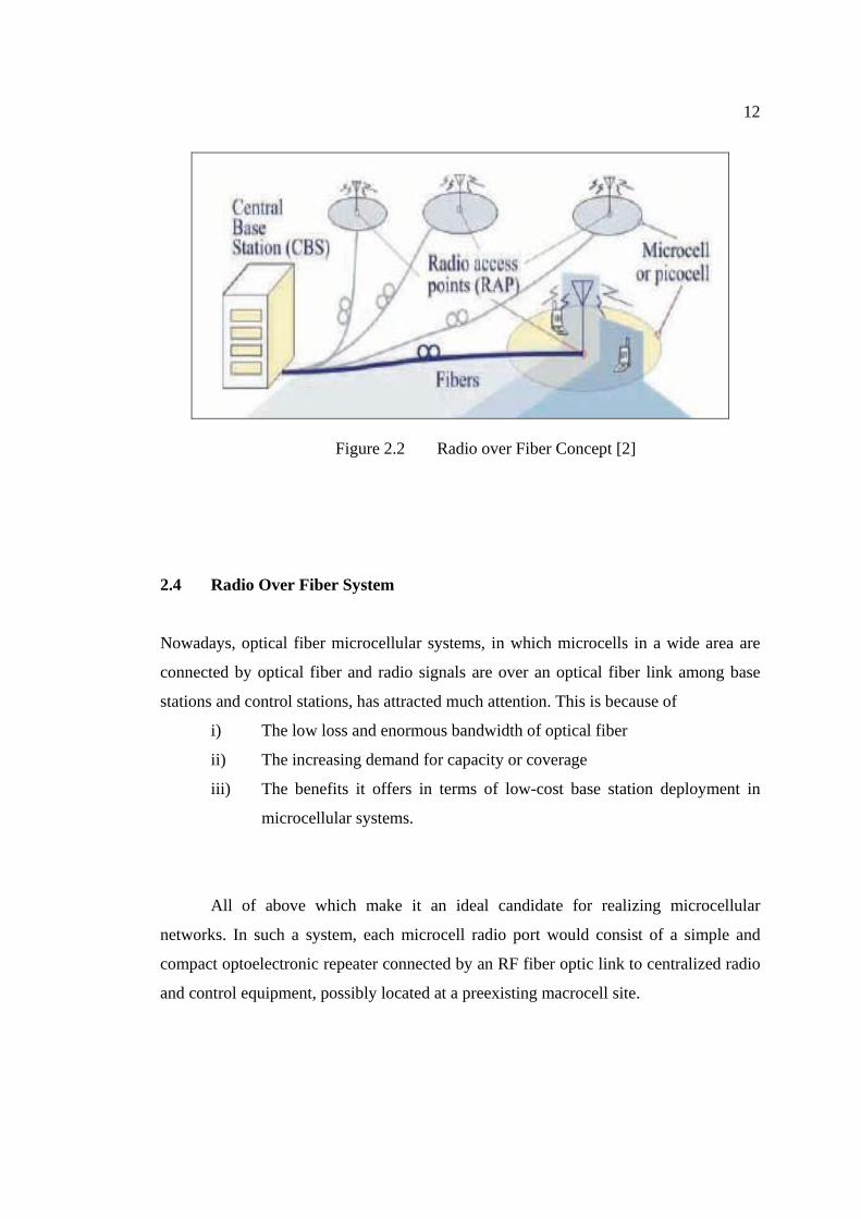
2.3 The Radio Over Fiber Technology
Radio over Fiber concept is already shown in Figure 2.1. This solution increase
the frequency reuse enables broadband access by providing a micro/pico cell scenario
for cellular radio networks. The micro/pico cell scenario is possible through the use of
radio access point (RAP) in Figure 2.2. These inexpensive low power RAPs provide
wireless access instead of conventional base stations. It is important to keep the RAPs
complexity and cost at a minimum in order to allow for large scales deployment. By
doing so, a large cell can easily be split into smaller cells by dispersing RAPs
throughout. The robust RAPs are connected to the central base station via the RoF links.
12
Figure 2.2 Radio over Fiber Concept [2]
2.4 Radio Over Fiber System
Nowadays, optical fiber microcellular systems, in which microcells in a wide area are
connected by optical fiber and radio signals are over an optical fiber link among base
stations and control stations, has attracted much attention. This is because of
i) The low loss and enormous bandwidth of optical fiber
ii) The increasing demand for capacity or coverage
iii) The benefits it offers in terms of low-cost base station deployment in
microcellular systems.
All of above which make it an ideal candidate for realizing microcellular
networks. In such a system, each microcell radio port would consist of a simple and
compact optoelectronic repeater connected by an RF fiber optic link to centralized radio
and control equipment, possibly located at a preexisting macrocell site.
13
Use of RF antenna remoting allows changes to the system frequency plan or
modulation format to be done at a central location, without the need to modify any radio
port equipment. Antenna remoting should also simplify the provision of system features
such as rapid handover, dynamic channel assignment and diversity combining.
This system will make extensive use of microcells and picocells in order to
deliver high bandwidth. Such microcell systems can solve the frequency limitation
problems because a number of base stations can be installed, the zone radius can be
reduced and the radio frequencies can be reused effectively in many radio zones. The
much lower power level eliminates the need for the expensive frequency multiplexes or
high-power amplifiers currently employed at base stations. The limited coverage due to
low antenna height greatly reduces the co-channel interference from other cells. RoF
systems are now being used extensively for enhanced cellular coverage inside buildings
such as offices, shopping malls and airport terminals.
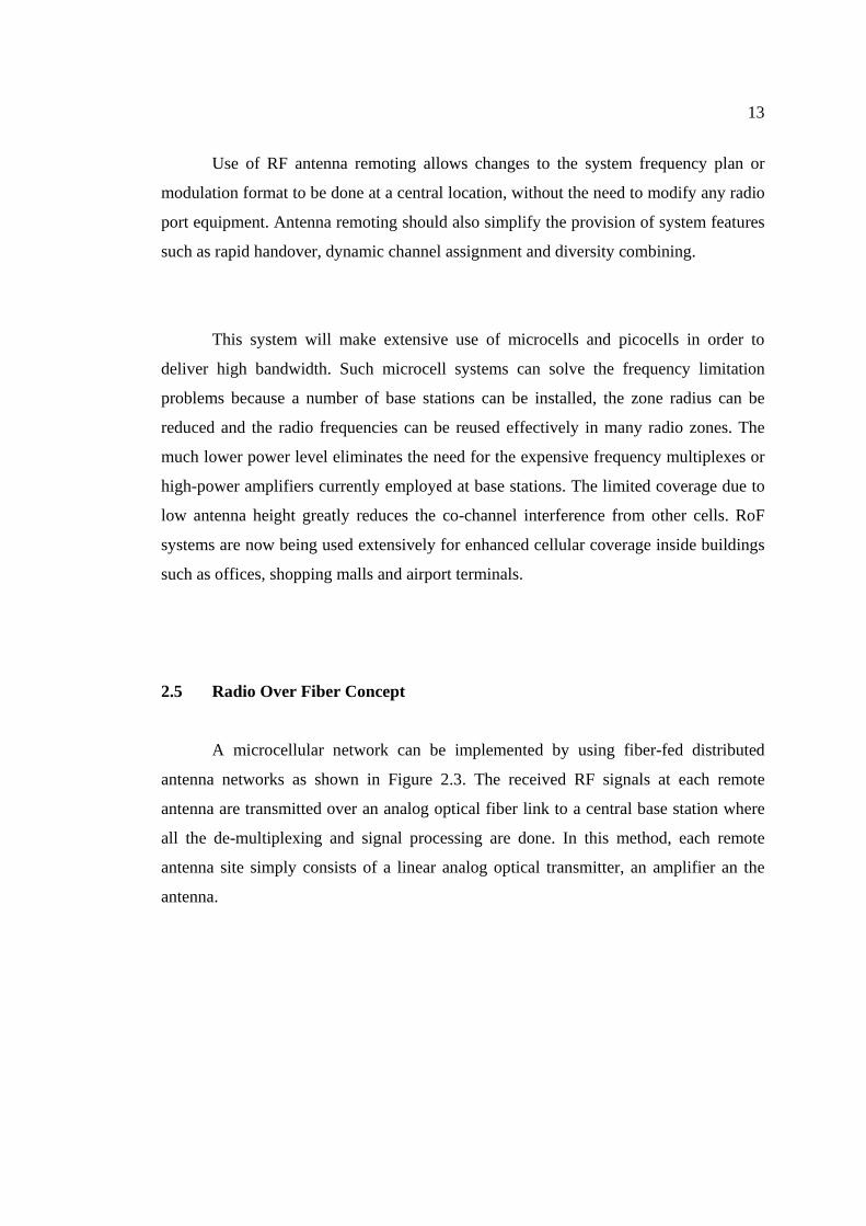
2.5 Radio Over Fiber Concept
A microcellular network can be implemented by using fiber-fed distributed
antenna networks as shown in Figure 2.3. The received RF signals at each remote
antenna are transmitted over an analog optical fiber link to a central base station where
all the de-multiplexing and signal processing are done. In this method, each remote
antenna site simply consists of a linear analog optical transmitter, an amplifier an the
antenna.
14
Figure 2.3 Optically fed remote antenna network for microcellular RoF systems [1]
15
2.6 Advantages of Using RoF In Mobile Communication Networks
The radio network is a distributed antenna system with the potential for adaptive
antenna selection as well as adaptive channel allocation to increase the spectrum
efficiency. The distributed antenna system provides an infrastructure that brings the
radio interface very close to the users and has the following benefits:
i) Low RF power remote antenna points (RAPs)
ii) Line-of sight (LOS) operation (multipath effects are minimized)
iii) Enabling of mobile broadband radio access close to the user in an
economically acceptable way
iv) Reduced environment impact (small RAPs)
v) Good coverage
vi) Capacity enhancement by means of improved trucking efficiency
vii) Dynamic radio resource configuration and capacity allocation
viii) Alleviation of the cell planning problem
ix) Reduction in the number of handovers
x) Centralized upgrading or adaptation
xi) The potential to deploy precision tracking of user equipment for safety/first
aid and other purposes
xii) Higher reliability and lower maintenance costs
xiii) Support for future broadband multimedia applications
xiv) Better coverage and increased capacity
xv) High-quality signals
xvi) Support for macro diversity transmissions
xvii) Low fiber attenuation (up to 0.2dB/km)
xviii) Reduced engineering and system design costs
xix) Multiple services on a single fiber
xx) Lightweight fiber cables
xxi) No electromagnetic interference
xxii) Reliability
16
The use of low RF power RAPs has following advantages:
i) Low generated interference
ii) Increased spectrum efficiency
iii) Easier frequency/network planning
iv) Increased battery lifetime of mobile terminals
v) Relaxed human health issues
vi) The potential to use RF complementary metal oxide semiconductor
technology in mobile terminals
2.7 Benefits of Radio over Fiber Systems
2.7.1 Low Attenuation Loss
Electrical distribution of high frequency microwave signals either in free space
or through transmission lines is problematic and costly. In free space, losses due to
absorption and reflection increase with frequency. In transmission lines, impedance rises
with frequency as well. Therefore, distributing high frequency radio signals electrically
over long distances requires expensive regenerating equipment. As for mm-waves, their
distribution via the use of transmission lines is not feasible even for short distances. The
alternative solution to this problem is to distribute baseband signals or low intermediate
frequencies (IF) from the Switching Centre (SC) to the Base Stations (BS). The
baseband or IF signals are then up converted to the required microwave or mm-wave
frequency at each base station, amplified and then radiated. Such a system places
stringent requirements (such as linearity) on repeater amplifiers and equalisers. In
addition, high performance local oscillators would be required for up conversion at each
base station. This arrangement leads to complex base stations with tight performance
requirements. An alternative solution is to use optical fibers, which offer much lower
losses.

17
Commercially available standard Single Mode Fiber (SMFs) made from glass
(silica) have attenuation losses below 0.2 dB/km and 0.5 dB/km in the 1.5 µm and the
1.3 µm windows, respectively. Polymer Optical Fiber (POFs), a more recent kind of
optical fibers exhibit higher attenuation ranging from 10 – 40 dB/km in the 500 - 1300
nm regions. These losses are much lower than those encountered in free space
propagation and copper wire transmission of high frequency microwaves. Therefore, by
transmitting microwaves in the optical form, transmission distances are increased
several folds and the required transmission powers reduced greatly.
2.7.2 Large Bandwidth
Optical fibers offer enormous bandwidth. There are three main transmission
windows, which offer low attenuation, namely the 850 nm, 1310 nm and 1550 nm
wavelengths. For a single SMF optical fiber, the combined bandwidth of the three
windows is in the excess of 50 THz . However, today’s state-of-the-art commercial
systems utilize only a fraction of this capacity (1.6 THz). But developments to exploit
more optical capacity per single fiber are still continuing. The main driving factors
towards unlocking more and more bandwidth out of the optical fiber include the
availability of low dispersion (or dispersion shifted) fiber, the Erbium Doped Fiber
Amplifier (EDFA) for the 1550 nm window, and the use of advanced multiplex
techniques namely Optical Time Division Multiplexing (OTDM) in combination with
Dense Wavelength Division Multiplex (DWDM) techniques.
The enormous bandwidth offered by optical fibers has other benefits apart from
the high capacity for transmitting microwave signals. The high optical bandwidth
enables high speed signal processing that may be more difficult or impossible to do in
electronic systems. In other words, some of the demanding microwave functions such as
18
filtering, mixing, up- and down-conversion, can be implemented in the optical domain.
For instance, mm-wave filtering can be achieved by first converting the electrical signal
to be filtered into an optical signal, then performing the filtering by using optical
components such as the Mach Zehnder Interferometer MZI or Bragg gratings), and then
converting the filtered signal back into an electrical signal. Furthermore, processing in
the optical domain makes it possible to use cheaper low bandwidth optical components
such as Laser Diodes (LD) and modulators, and still be able to handle high bandwidth
signals.
The utilization of the enormous bandwidth offered by optical fiber is severely
hampered by the limitation in bandwidth of electronic systems, which are the primary
sources and end users of transmission data. This problem is referred to as the
“electronic bottleneck”.
The solution around the electronic bottleneck lies in effective multiplexing.
OTDM and DWDM techniques mentioned above are used in digital optical systems. In
analog optical systems including RoF technology, Sub-Carrier Multiplexing (SCM) is
used to increase optical fiber bandwidth utilization. In SCM, several microwave sub
carriers, which are modulated with digital or analog data, are combined and used to
modulate the optical signal, which is then carried on a single fiber. This makes the RoF
system costs effective.
2.7.3 Immunity to Radio Frequency Interference
Immunity to electromagnetic interference is a very attractive property of optical
fiber communications, especially for microwave transmission. This is so because signals
are transmitted in the form of light through the fiber. Because of this immunity, fiber
19
cables are preferred even for short connections at mm-waves. Related to RFI immunity
is the immunity to eavesdropping, which is an important characteristic of optical fiber
communications, as it provides privacy and security.
2.7.4 Easy Installation and Maintenance
In RoF systems, complex and expensive equipment is kept at the SCs, thereby
making remote base stations simpler. For instance, most RoF techniques eliminate the
need for a local oscillator and related equipment at the Remote Station (RS). In such
cases a photo detector, an RF amplifier, and an antenna make up the RS equipment.
Modulation and switching equipment are kept in the SC at the head end and shared by
several RS. This arrangement results in smaller and lighter RS, effectively reducing
system installation and maintenance costs. Easy installation and low maintenance costs
of RS are very important requirements for mm-wave systems, because of the large
numbers of the required antenna sites. Having expensive RS would render the system
costs prohibitive. The numerous antennas are needed to offset the small size of radio
cells (microcells and picocells), which is a consequence of limited propagation distances
of mm-wave microwaves. In applications where RSs are not easily accessible, the
reduction in maintenance requirements has many positive implications.
2.7.5 Reduced Power Consumption
Reduced power consumption is a consequence of having simple RSs with
reduced equipment. Most of the complex equipment is kept at the central SC. In some
applications, the antenna sites are operated in passive mode. For instance, some 5 GHz
Fiber-Radio systems employing picocells (small radio cells) can have the RSs (BSs)
operate in passive mode. Reduced power consumption at the RSs is significant
20
considering that RSs are sometimes placed in remote locations not fed by the power
grid.
2.7.6 Operational Flexibility
RoF does offer operational benefits in terms of operational flexibility. Firstly,
depending on the microwave generation technique, a RoF distribution system can be
made signal format transparent. For instance the Intensity Modulation and Direct
Detection (IMDD) technique can be made to operate as a linear system and therefore as
a transparent system.
This can be achieved by using low dispersion fiber (SMF) in combination with
pre modulated RF sub carriers (SCM). When this happens, then, the same RoF network
can be used to distribute multi-operator and multi-service traffic, resulting in huge
economic savings.
Secondly, with the switching, modulation, and other functions performed at a
centralized SC, it is possible to allocate capacity dynamically. For instance in a RoF
based distribution system for GSM traffic, more capacity can be allocated to an area
(e.g. shopping mall) during peak times and then re-allocated to other areas when off-
peak (e.g. to populated residential areas in the evenings). This can be achieved by
allocating optical wavelengths as need arises. Allocating capacity dynamically as need
for it arises obviates the requirement for allocating permanent capacity, which would be
a waste of resources in cases where traffic loads vary frequently and by large margins.
Furthermore, having a SC facilitates the consolidation of other signal processing
functions such as mobility functions.

21
2.7.7 Millimeter Waves
Millimeter waves offer several benefits. However, mm-waves cannot be
distributed electrically due to high RF propagation losses. In addition, generating mm-
wave frequencies using electrical devices is challenging. These issues describe the
electronic bottleneck already discussed above. The most promising solution to the
problem is to use optical means. Low attenuation loss and large bandwidth make the
distribution of mm-waves cost effective. Furthermore, some optical based techniques
have the ability to generate unlimited frequencies. For instance, microwave frequencies
that can be generated by Remote Heterodyning and Detection (RHD) methods are
limited only by the bandwidth of photo detectors.
2.7.7.1 Advantages of mm-waves
They provide high bandwidth due to the high frequency carriers. Secondly, due
to high RF propagation losses in free space, the propagation distances of mm-waves are
severely limited. This allows for well-defined small radio sizes (microcells and
picocells), where considerable frequency re-use becomes possible so that services can
be delivered simultaneously to a larger number of subscribers.
2.7.7.2 Disadvantages of mm-waves
The negative side of mm-waves is the need for numerous BSs, which is a
consequence of high RF propagation losses. Unless the BSs are simple enough,
installing and maintaining the mm-wave system can be economically prohibitive owing
to the numerous required BSs.
22
2.7.8 Radio System Functionalities
As stated earlier, RoF technology is not only used for distributing RF signals but
for radio system functionalities as well. Among these, modulation and frequency
conversion have been mentioned above. However, application of RoF technology for
radio system functionalities goes beyond modulation and frequency conversion to
encompass signal processing at very high frequencies. These functions include filtering,
attenuation control and signal processing in high frequency phased array antenna
systems, just to name but a few. These functions are also referred to as microwave
functions. Many of these functions are difficult to achieve in the microwave (electrical)
domain due to limited bandwidth and other electromagnetic wave propagation
limitations. However, if the processing is done in the optical domain, unlimited signal
processing bandwidth becomes available. As a result, many microwave functions can be
performed by optical components without needing E/O conversion for processing by
microwave components and vice versa.
2.8 Applications of Radio over Fiber Technology
Some of the applications of RoF technology include satellite communications,
mobile radio communications, broadband access radio, Multipoint Video Distribution
Services (MVDS), Mobile Broadband System (MBS), vehicle communications and
control, and wireless LANs over optical networks. The main application areas are
briefly discussed next.

23
2.8.1 Cellular Networks
The field of mobile networks is an important application area of RoF technology.
The ever-rising number of mobile subscribers coupled with the increasing demand for
broadband services have kept sustained pressure on mobile networks to offer increased
capacity. Therefore, mobile traffic (GSM or UMTS) can be relayed cost effectively
between the SCs and the BSs by exploiting the benefits of SMF technology. Other RoF
functionalities such as dynamic capacity allocation offer significant operational benefits
to cellular networks.
2.8.2 Satellite Communications
Satellite communications was one of the first practical uses of RoF technology.
One of the applications involves the remoting of antennas to suitable locations at
satellite earth stations. In this case, small optical fiber links of less than 1km and
operating at frequencies between 1 GHz and 15 GHz are used. By so doing, high
frequency equipment can be centralized.
The second application involves the remoting of earth stations themselves. With
the use of RoF technology the antennae need not be within the control area (e.g.
Switching Centre). They can be sited many kilometers away for the purpose of, for
instance improved satellite visibility or reduction in interference from other terrestrial
systems. Switching equipment may also be appropriately sited, for say environmental or
accessibility reasons or reasons relating to the cost of premises, without requiring to be
in the vicinity of the earth station antennas.
24
2.8.3 Video Distribution Systems
One of the major promising application areas of RoF systems is video
distribution. A case in point is the Multipoint Video Distribution Services (MVDS).
MVDS is a cellular terrestrial transmission system for video (TV) broadcast. It was
originally meant to be a transmit-only service but recently, a small return channel has
been incorporated in order to make the service interactive. MVDS can be used to serve
areas the size of a small town.
Allocated frequencies for this service are in the 40 GHz band. At these
frequencies, the maximum cell size is about 5 km. To extend coverage, relay stations are
required. In MVDS a transmitter serves the coverage area, which is located either on a
mast or a tall building. The rooftop equipment can be simplified by employing RoF
techniques. For instance, instead of using Gunn oscillators with their own antennas and
heat pipes for frequency stabilization, an optical fiber link may be used to feed either a
traveling wave tube or a solid state amplifier at the transmit frequency. This greatly
reduces the weight and wind loading of the transmitter. In addition, a single optical fiber
could feed the transmitter unit from a distance of several hundred meters.
2.8.4 Mobile Broadband Services
The Mobile Broadband System or Service (MBS) concept is intended to extend
the services available in fixed Broadband Integrated Services Digital Network (B-ISDN)
to mobile users of all kinds. Future services that might evolve on the B-ISDN networks
must also be supported on the MBS system. Since very high bit rates of about 155 Mbps
per user must be supported, carrier frequencies are pushed into mm-waves. Therefore,
frequency bands in the 60 GHz band have been allocated. The 62-63 GHz band is
allocated for the downlink while 65-66 GHz is allocated for the uplink transmission.
25
The size of cells is in diameters of hundreds of meters (microcells). Therefore, a high
density of radio cells is required in order to achieve the desired coverage. The micro-
cells could be connected to the fixed B-ISDN networks by optical fiber links. If RoF
technology is used to generate the mm-waves, the base stations would be made simpler
and therefore of low cost, thereby making full scale deployment of MBS networks
economically feasible.
2.8.5 Wireless LANs
As portable devices and computers become more and more powerful as well as
widespread, the demand for mobile broadband access to LANs will also be on the
increase. This will lead once again, to higher carrier frequencies in the bid to meet the
demand for capacity. For instance current wireless LANs operate at the 2.4 GHz ISM
bands and offer the maximum capacity of 11 Mbps per carrier (IEEE 802.11b). Next
generation broadband wireless LANs are primed to offer up to 54 Mbps per carrier, and
will require higher carrier frequencies in the 5 GHz band (IEEE 802.11a/D7.0).
Higher carrier frequencies in turn lead to microcells and picocells, and all the
difficulties associated with coverage discussed above arise. A cost effective way around
this problem is to deploy RoF technology. A wireless LAN at 60 GHz has been released
by first transmitting from the BS, a stable oscillator frequency at an IF together with the
data over the fiber. The oscillator frequency is then used to up-convert the data to mm-
waves at the transponders (Remote Stations). This greatly simplifies the remote
transponders and also leads to efficient base station design.
26
2.8.6 Vehicle Communication and Control
This is another potential application area of RoF technology. Frequencies
between 63-64 GHz and 76-77 GHz have already been allocated for this service within
Europe. The objective is to provide continuous mobile communication coverage on
major roads for the purpose of Intelligent Transport Systems (ITS) such as Road-to-
Vehicle Communication (RVC) and Inter-Vehicle Communication (IVC). ITS systems
aim to provide traffic information, improve transportation efficiency, reduce burden on
drivers, and contribute to the improvement of the environment. In order to achieve the
required (extended) coverage of the road network, numerous base stations are required.
These can be made simple and of low cost by feeding them through RoF systems,
thereby making the complete system cost effective and manageable.
2.9 Summary
More general knowledge about Radio over Fiber has been written in this chapter.
So the reader will become familiar with this system and know how the systems
operated. Generally radio-over-fiber have considered millimeter wave radio-over-fiber
transmission. Millimeter wave radio, operating at 26-28 GHz or 60 GHz, was seen as
the logical choice for high bandwidth data transmission. Radio waves operating at this
frequency are attenuated greatly by the atmosphere, and so fiber was employed as an
alternate transmission media. Fiber dispersion has limited the success of radio-over-fiber
transmission of signals at these frequencies, particularly for fiber lengths exceeding 10
km.
27
CHAPTER 3
WIDEBAND CODE DIVISION MULTIPLE ACCESS
(WCDMA)
3.1 Introduction
This chapter is further information and details about WCDMA as well. As a
chapter that consult in order to understand and investigate this research project, further
explanatory will discuss and describe the parameters of WCDMA, an overview of
WCDMA, basic WCDMA transmission technologies, characteristics of WCDMA which
is more on technical site and last but not least is about the wideband properties of
WCDMA that allow higher efficiency from several aspects.
3.2 RoF Using WCDMA
The WCDMA air interface can now be regarded as a mature technology that is
ready to provide the basis for the third-generation wireless personal communication
systems know as the UMTS [1]. These systems will make extensive use of microcells
and picocells in order to deliver high bandwidth services to customers. The benefit of
28
using RoF for WCDMA distributed antenna systems is expected to be even more
important, partly because of their higher frequency and bandwidth requirements.
Two key features are expects to be employed in the UMTS system to minimize
multiple-user interference: adaptive antenna arrays and fast closed-loop forward and
reverse power control techniques. Other important techniques that are used to reduce
multiple-user interference are cell sectorization and voice activity monitoring,
particularly in speech-oriented cellular systems.
The UMTS is designed to support simultaneous transmission of multiple
services and data rates including video. One of the major drawbacks in RoF systems is
laser diode nonlinearity, which gives rise to intermodulation distortion and clipping
noise. It is well known that intermodulation distortion and clipping noise are signal level
dependent. So WCDMA RoF systems, voice activity monitoring will have an impact not
only on multiple-user interference but also on intermodulation distortion and clipping
noise power.
There are several researchers that report on applications in WCDMA RoF. In
Hamed Al-Raweshidy paper about ‘Radio over Fiber Technology for The Next
Generation’ has presented the main elements of the optical devices and the parameters
related to radio over fiber; laser diode performance, intermodulation, RIN and clipping
noise [1]. This paper discusses in more detail the system performance of RoF on
UMTS/WCDMA system. He also reported that an analytical model for evaluating the
performance of WCDMA-based RoF systems with numerical results showed an
improvement in performance when the effect of voice activity monitoring on
intermodulation distortion and clipping noise was taken into account.
29
Another paper from Hamed Al-Raweshidy and Nazem Khashjori with title
‘System Level Performance of WCDMA with RoF access network’ was reported that
the system-levelperformance of WCDMA with Radio-over-Fibre (RoF) access network
is investigated [15]. This paper aims at addressing issues such as coverage and transmits
power reduction during Macrodiversity. The simulation results demonstrate that, for a
given service, the transmit power reduction is up to 50% (depending on the channel
model and the mobile speed) in the case of the RoF technique as compared to the
wireless link. Macrodiversity is a technique in which multiple antennas are employed at
the receiver to form the branches for the diversity combiner, has the ability to improve
both uplink and downlink performance of wireless communications systems. When
Macrodiversity is combined with the use of fiber optic feeders, the results are
exceptionally promising.
The main aim of the system-level simulations is to help to perform more
practical link level simulations, by providing information about the effect of the
environment in a given link. The information from the RoF link-level simulations
Khashjori is brought to the system level as look-up tables. The most important numbers
are the Eb/No requirement for the services used and for the chosen mobile speed, both
in the uplink and downlink and the orthogonality factor in the DL. The numbers in the
tables depend on the channel model [15].
This paper has presented an evaluation of the WCDMA network with radio over
fiber. All methods used in this system are according to 3GPP UTRA standards. The
System level of WCDMA with RoF and wireless access was investigated. The
propagation model effect and cell loading has been analysed. The results show that there
is significant power reduction available for each link (up to 50%) when using RoF
techniques. In conclusion of this paper, the use of RoF technology can he used to
improve the performance of WCDMA [15].

30
For paper ‘Fiber-Wireless Solution for Broadband Multimedia Access’ that has
written by Stephen Z. Pinter and Xavier N. Fernando had reported about the increasing
demand for high-capacity multimedia services in real-time demands wireless broadband
access [10]. In order to meet this demand, a fiber based wireless access scheme using
radio-over-fiber (RoF) technology can be used and is discussed in this article. Fiber
based wireless (Fi-Wi) access schemes effectively combine the high capacity of optical
fiber with the flexibility of wireless networks. This approach enables rapid deployment
of microcells in cellular radio networks for capacity enhancement. Furthermore, a single
sub-carrier multiplexed RoF link can support wireless LAN, cellular radio, and CATV
services simultaneously. RoF technology can also transmit millimeter radio waves to the
surrounding neighborhood for LMCS type systems. The focus of research group
ADROIT is to investigate various issues in this scenario such that RoF becomes a
feasible technology to provide a cost-effective, high performance solution for broadband
access. They have devised a system identification technique for a concatenated fiber-
wireless channel, and have proposed various compensation schemes to equalize the time
varying linear wireless plus static nonlinear optical channel. Another of their projects
focuses on supporting both cellular CDMA and IEEE 802.11 signals over the fiber-
wireless channel. They have also performed various experimental studies on the RoF
approach and have been working with optical and electrical signal processing for
performance improvement. This article provides an overview of ADROIT research and
presents some noteworthy results [10].
In paper title ‘WCDMA-Based Radio over Fiber System Performance with
Multiple-User Interference in Multiple Service Transmission’ by H.S. Al-Raweshidy
and S.O. Ampem-Darko had reported about intermodulation distortion and clipping
noise due to laser diode nonlinearity constitute a major source of interference and noise
in radio-over-fiber systems [12]. These noises are known to be signal level dependent.
This paper proposes an analytical model for evaluating performance of radio-over-fiber
systems. Numerical results presented showed 4.5 dB improvement in performance when
31
taken into account effect of mobile radio discontinuous transmission mode on
intermodulation distortion and clipping noise.
RoF application has attracted much attention recently because of the increasing
demand for capacity/coverage and,the benefits it offers in terms of low-cost base
stations deployment in microcellular systems. RoF systems are now being used
extensively for enhanced cellular coverage inside buildings such as office blocks,
shopping malls and airport terminal. Wideband Code Division Multiple Access
(WCDMA), air interface can now be regarded as a mature technology ready to provide
the basis for the third generation wireless personal communication systems, known as
Universal Mobile Telecommunication Systems (UMTS). These systems will make
extensive use of microcells and picocells in order to deliver high bandwidth services to
customers. The benefit of using RoF for WCDMA distributed antenna systems is
expected to be even more important, partly because of their higher frequency and
bandwidth requirements. Two key features are expected to be employed in the UMTS
system to minimize multiple-user interference (MUI) namely, adaptive antenna arrays,
and fast closed-loop forward and reverse power control techniques [12].

32
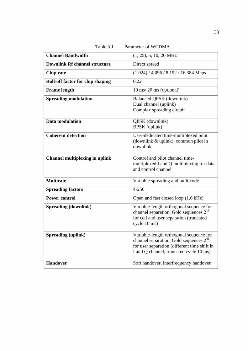
3.3 Parameter Of WCDMA
Every multiple access has their parameter to suit the application that supported
by them. Thus, same to WCDMA that suit to radio over fiber application has their own
parameter. As written in Table 3.1 below is suitable parameter for WCDMA using RoF.
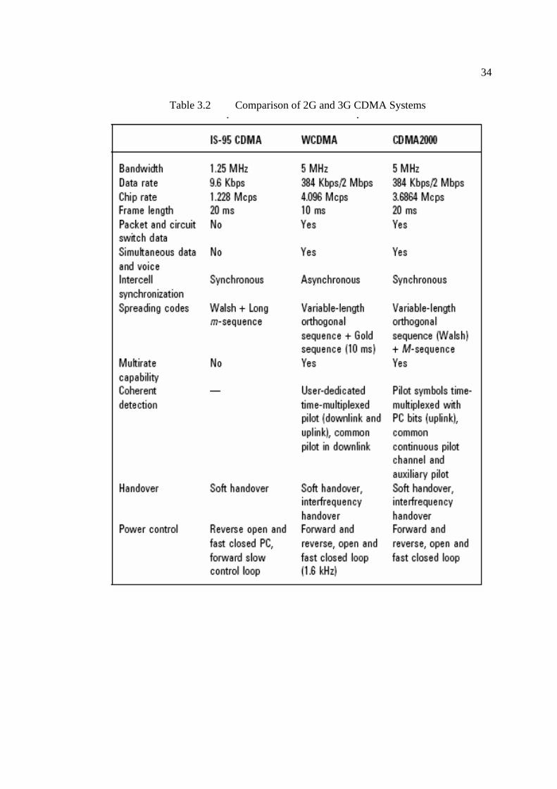
There also have comparison between various CDMA parameter. Table 3.2 show
that the similar and differences between three types of CDMA that normally use in our
communication systems. The differences are from their bandwidth, data rate, chip rate,
frame length, intercell synchronization, spreading codes, multirate capability and etc.
Besides that, there are several parameters using the same method but different in other
method.
The different factors that influence capacity in WCDMA and 3G mobile
systems, such as traffic type (data, voice, and SMS), propagation model, terrain, user
mobility, sectorization, and cell overlap.
33
Table 3.1 Parameter of WCDMA
Channel Bandwidth (1, 25), 5, 10, 20 MHz
Downlink Rf channel structure Direct spread
Chip rate (1.024) / 4.096 / 8.192 / 16.384 Mcps
Roll-off factor for chip shaping 0.22
Frame length 10 ms/ 20 ms (optional)
Spreading modulation Balanced QPSK (downlink) Dual channel (uplink) Complex spreading circuit
Data modulation QPSK (downlink) BPSK (uplink)
Coherent detection User-dedicated time-multiplexed pilot (downlink & uplink), common pilot in downlink
Channel multiplexing in uplink Control and pilot channel time-multiplexed I and Q multiplexing for data and control channel
Multirate Variable spreading and multicode
Spreading factors 4-256
Power control Open and fast closed loop (1.6 kHz)
Spreading (downlink) Variable-length orthogonal sequence for channel separation, Gold sequences 218 for cell and user separation (truncated cycle 10 ms)
Spreading (uplink) Variable-length orthogonal sequence for channel separation, Gold sequences 241 for user separation (different time shift in I and Q channel, truncated cycle 10 ms)
Handover Soft handover, interfrequency handover
34
Table 3.2 Comparison of 2G and 3G CDMA Systems

35
3.4 WCDMA Overview
WCDMA has emerged as the most widely adopted air interface technology for Third
Generation systems. The 3GPP consortium has created specifications for the use of
WCDMA technology in its networks, where it is referred to as the UTRA (Universal
Terrestrial Radio Access). Evolved from the CDMA radio access scheme, WCDMA is a
Wideband Direct-Sequence CDMA (DS-CDMA) system. To understand this definition,
it is imperative to understand some of the terms/concepts used with respect to WCDMA:
Direct-Sequence CDMA
Wideband
Synchronization Aspects
Modes of Operation
3.4.1 Direct-Sequence CDMA
The term ‘Direct-Sequence CDMA (DS-CDMA)’ stems from the ‘Direct-
Sequence Spread Spectrum (DSSS)’ technique used in DS-CDMA. The CDMA scheme
uses the concept of spreading codes to transform the user signal into a spread-spectrum-
coded signal. These spreading codes are used to provide access to multiple users
simultaneously. Multiple spreading techniques exist: notable among them are the DSSS
and the ‘Frequency Hopping Spread Spectrum (FHSS)’.
The DSSS uses a carrier that remains fixed to a specific frequency band. The
data signal is spread onto a much larger range of frequencies using a specific encoding
scheme, rather than being transmitted on a narrow band. This encoding scheme is
known as Pseudo-Noise sequence (PN sequence). Frequency Hopping Spread Spectrum,
on the other hand, attempts to achieve the same result by sending its transmissions over
a different carrier frequency at different times. DSSS is the simpler of the spreading
36
techniques, whereby the original signal is directly multiplied by a faster-rate spreading
code.
3.4.2 Wideband
In WCDMA, the term Wideband refers to the higher bandwidth carrier signal of
approximately 5 MHz. Original DS-CDMA systems, like the IS-95, used a carrier
bandwidth of about 1 MHz. These systems are referred to as Narrowband CDMA
systems. In contrast, WCDMA is a CDMA based access scheme, which uses the DSSS
spreading techniques with a carrier bandwidth of around 5 MHz. The higher carrier
bandwidth makes WCDMA a wideband system.
3.4.3 Synchronization Aspects
The proposal for WCDMA radio interface are broadly divided into two
categories, network synchronous and network asynchronous, depending upon whether
the base stations within the network are synchronized in time or not. A network where
the base stations are time synchronized with each other are categorized as synchronous
networks. If synchronization between base stations is not required, then such a network
is termed as an asynchronous network. Second Generation IS-95 systems are based on
the synchronous network concept. Though synchronized network provide more efficient
utilization of the radio interface, it requires a lot of functionality within the base station
and hence more costly hardware. Additional techniques, like Global Positioning System
(GPS), would be required to time synchronize the base stations. These further places a
restriction on deployment of base stations-indoor and micro base stations can only be
deployed if the GPS signals can be received indoors. While Third Generation systems
37
based on the 3GPP specifications utilize the asynchronous network based scheme,
CDMA2000 based proposals use schemes that are synchronous network based.
3.4.4 Modes of Operation
WCDMA supports two basic modes of operation: one for paired spectrum and
the other for the unpaired spectrum. Here, pairing refers to the frequency bands
available for communication. The Frequency Division Duplex (FDD) mode is used for
the paired spectrum, while for unpaired spectrum; it is the Time Division Duplex (TDD)
mode.
In the FDD mode of operation, separate 5 MHz carrier frequencies are used in
the uplink and the downlink direction. Since two frequency bands of equal bandwidths
are available, one is used for uplink direction (from mobile station to base station) and
the other for downlink direction (from base station to mobile station). Thus, the
information transfer in FDD mode is symmetric. Further, data can be exchanged in both
directions simultaneously. The traditional GSM uses the FDD mode.
In the TDD mode of operation, only one 5 MHz carrier is time-shared between
the uplink and the downlink. Since only one frequency band is available, The TDD is
said to use the unpaired spectrum. The data is alternated in the uplink and downlink
direction. The main benefit of TDD mode is that the bandwidths in forward and
backward direction can be altered. Thus, it is possible that the downlink bandwidth is
much more than the uplink bandwidth. This is helpful in certain applications (downloads
from the Internet) where a small request is followed by large amounts of information.
The unpaired nature of TDD makes it use the spectrum more efficiently. Further, as the
spectrum becomes scarce, getting an unpaired spectrum will be easier as compared to

38
obtaining a paired spectrum. This will provide TDD an edge over FDD. It is presumed
that TDD will be used in hot spots (such as airports) to provide high data rate
connectivity efficiently.
In a certain sense, the FDD mode of operation can be considered as a hybrid
scheme that uses CDMA and FDMA schemes, since the CDMA scheme is applied
within each frequency channel. In other words, the TDD mode of operation uses a
hybrid scheme based on CDMA, FDMA and TDMA, as the same carrier frequency is
further time-shared for the uplink and the downlink direction. With this introduction to
WCDMA forming the basis of discussion. The underlying technique utilised in
WCDMA is the Direct Sequence Spread Spectrum (DSSS) whose main principles are
illustrated in Figure 3.1.
Figure 3.1 The basic techniques of the Direct Sequence Spread Spectrum [5]
39
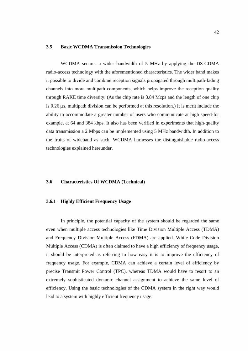
Figure 3.2(a) shows how DS-CDMA works and Figures 3.4 shows how the
signal of DS-CDMA is spread. The transmitted data sequence is spread across the
spectrum after being encoded by spreading codes, each of which is assigned uniquely to
each user at a higher rate than the symbol rate of the information data. WCDMA spreads
the information data over a 5 MHz band per carrier. The spread high-speed data
sequence is referred to as chip and the rate at which the spread data varies is called chip
rate. The ratio of chip rate to symbol rate is called the spreading factor (SF). The
destination mobile phone uses the same spreading code as the one used for spreading at
the transmission point to perform correlation detection (a process called dispreading), in
order to recover the transmitted data sequence. As signal received by other users carry
different spreading codes, the signal power is reduced evenly to 1/SF. In DS-CDMA, all
users share the same frequency band and time frame to communicate and each user is
identified by a spreading code uniquely assigned to the user.
In contrast, as shown in Figure 3.2(b), FDMA assigns to each user a different
carrier frequency, depending on the frequency generated in the frequency synthesizer
and TDMA assign to each user not only a carrier frequency but also a time slot to
engaged in communications. At the reception point, the frequency generated by the
frequency synthesizer is set in such a manner that the signals in the assigned carrier
frequency can be down converted in the destination mobile phone and the transmitted
data sequence is extracted from specific slots with reference to the demodulated signals.
In DS-CDMA, there is basically no need to assign carrier frequencies or time slot as
such to the users.

40
Figure 3.2 Principles of DS-CDMA [4]
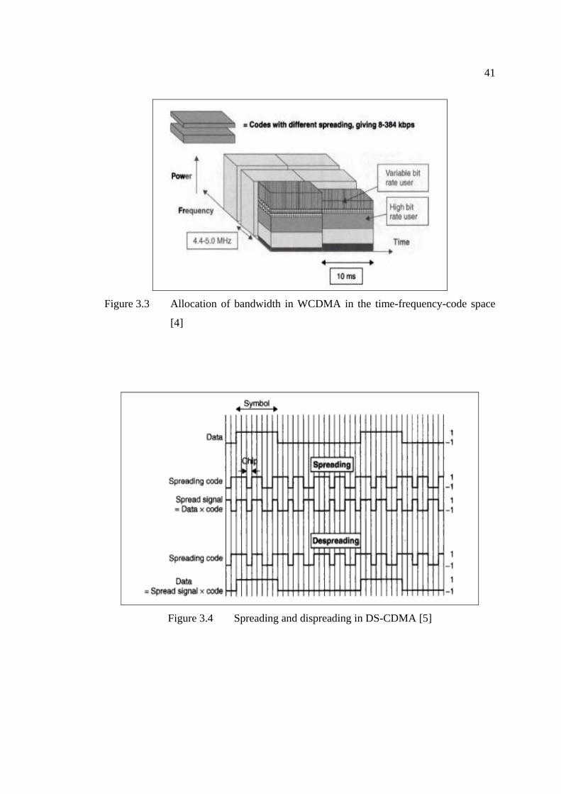
Figure 3.3 is shown an arrangement in WCDMA, which is a wideband Direct-
Sequence Code Division Multiple Access (DS-CDMA) system such as user information
bits are spread over a wide bandwidth by multiplying the user data with quasi-random
bits (called chips) derived from CDMA spreading codes. In order to support very high
bit rates (up to 2 Mbps), the use of variable spreading factor and multicode connections
is supported.
41
Figure 3.3 Allocation of bandwidth in WCDMA in the time-frequency-code space
[4]
Figure 3.4 Spreading and dispreading in DS-CDMA [5]
42
3.5 Basic WCDMA Transmission Technologies
WCDMA secures a wider bandwidth of 5 MHz by applying the DS-CDMA
radio-access technology with the aforementioned characteristics. The wider band makes
it possible to divide and combine reception signals propagated through multipath-fading
channels into more multipath components, which helps improve the reception quality
through RAKE time diversity. (As the chip rate is 3.84 Mcps and the length of one chip
is 0.26 µs, multipath division can be performed at this resolution.) It is merit include the
ability to accommodate a greater number of users who communicate at high speed-for
example, at 64 and 384 kbps. It also has been verified in experiments that high-quality
data transmission a 2 Mbps can be implemented using 5 MHz bandwidth. In addition to
the fruits of wideband as such, WCDMA harnesses the distinguishable radio-access
technologies explained hereunder.
3.6 Characteristics Of WCDMA (Technical)
3.6.1 Highly Efficient Frequency Usage
In principle, the potential capacity of the system should be regarded the same
even when multiple access technologies like Time Division Multiple Access (TDMA)
and Frequency Division Multiple Access (FDMA) are applied. While Code Division
Multiple Access (CDMA) is often claimed to have a high efficiency of frequency usage,
it should be interpreted as referring to how easy it is to improve the efficiency of
frequency usage. For example, CDMA can achieve a certain level of efficiency by
precise Transmit Power Control (TPC), whereas TDMA would have to resort to an
extremely sophisticated dynamic channel assignment to achieve the same level of
efficiency. Using the basic technologies of the CDMA system in the right way would
lead to a system with highly efficient frequency usage.
43
3.6.2 Freedom From Frequency Administration
As CDMA allows adjacent cells to share the same frequency, no frequency
allocation plan is required. In contrast, FDMA and TDMA require frequency allocation-
in particular, much difficulty is involved in frequency allocation because of the way in
which stations are located in practice, as irregular propagation patterns and topographic
features need to be considered. It should also be noted that imperfect frequency
allocation designs diminish the efficiency of frequency usage. CDMA requires no
frequency allocation plan as such.
3.6.3 Low Mobile Station Transmit Power
CDMA can improve reception performance and reduce the transmission power
of Mobile Stations (MSs) by technologies like RAKE reception and so on. In TDMA,
transmission is intermittent; the peak power required for the transmission of 1 bit is
multiple times the number of TDMA multiplexes compared to continual transmission.
On the other hand, the peak power may be small in CDMA, as continual transmission is
possible. The additional merit of this feature is that it minimizes the impact to the
electromagnetic field.
3.6.4 Resources Used Independently in Uplink and Downlink
In CDMA, it is easy to support an asymmetric uplink and downlink
configuration. For example, in other access systems such as TDMA, it is difficult to
assign time slots for uplink and downlink configuration because the carrier bandwidth in
uplink and downlink would have to be changed. In contrast, in CDMA, the Spreading

44
Factor (SF) can be set independently between uplink and downlink for each user, and
thereby set different speeds in uplink and downlink. This allows the efficient use of
radio resources even in asymmetric communications, such as Internet access. When
there is no transmission, no radio resources are used; therefore, if one user is executing
transmission in uplink only, and another user is performing transmission in downlink
only, the radio resources being used are equivalent to one pair of uplink and downlink
resources. Generally, TDMA and FDMA would have to assign two pairs of radio
resources in such cases.
3.7 The Wideband Properties Of WCDMA Allow Higher Efficiency In The
Following Aspects
3.7.1 Wide Range of Data Speeds
Wideband enables transmission at high speed. It also enables the efficient
provision of services when there is a combination of low-speed services and high-speed
services.
For example, in TDMA, various transmission speeds can be offered by varying
the setting of the assigned number of time slots, but a low-speed, speech-only mobile
phone would still require the same peak power as the peak transmission power required
for maximum-speed services.
45
3.7.2 Improved Multipath Resolution
RAKE diversity reception technology improves the reception performance by
separating multipaths into individual paths for reception and combining. As wideband
improves the resolution of the propagation path, the required reception power need not
be high because of the path diversity effect brought about by the increased number of
paths. This helps reduce transmission power and increase capacity. A typical example of
this has been demonstrated in a field test revealing that the required transmission power
at approximately 4 Mcps is about 3 dB less than at approximately 1 Mcps.
3.7.3 Statistical Multiplexing Effect
Wideband increases the number of users to be multiplexed by each carrier.
Hence, the capacity increases because of the statistical multiplexing effect. The
characteristics of the statistical multiplexing effect are particularly evident in relatively
high-speed data communication: the efficiency decreases in narrowband, as the number
of channels that can be accommodated by each carrier is limited, whereas in wideband,
the efficiency improves because of the statistical multiplexing effect.
3.7.4 Reduced Intermittent Reception Rate
Wideband accelerates the bit rate in the control channel, and makes it possible to
reduce the rate of intermittent reception, which makes the mobile phone receive limited
46
signals when it is in idle mode for saving power. This extends the standby time of the
MS (Mobile Station).
3.8 Summary
From the above explanation, WCDMA an ITU standard derived from Code-
Division Multiple Access (CDMA), is officially known as IMT-2000 direct spread. W-
CDMA also known as third-generation (3G) mobile wireless technology that promises
much higher data speeds to mobile and portable wireless devices than commonly
offered in today's market.
W-CDMA can support mobile/portable voice, images, data, and video
communications at up to 2 Mbps (local area access) or 384 Kbps (wide area access).
The input signals are digitized and transmitted in coded, spread-spectrum mode over a
broad range of frequencies. A 5 MHz-wide carrier is used, compared with 200 kHz -
wide carrier for narrowband CDMA. Therefore utilization for WCDMA is bigger than
CDMA and very suitable for next generation, which is, the population become big every
year.
47
CHAPTER 4
SIMULATIONS
4.1 Introduction
This chapter will discuss simulations that already done by using RoF basic
design. There will be further explanation about simulations, result and discussion and
conclusion of this chapter.
4.2 Simulations
Several type of block simulink was designed and developed for this thesis
simulation. There are:
i) BPSK modulation (Figure 4.2)
ii) QPSK modulation (Figure 4.4)
iii) QPSK modulation using RoF.(Figure 4.5)

48
The performance of the simulink is measured using BER. BER (bit error rate) is
the percentage of bits with errors divided by the total number of bits that have been
transmitted, received or processed over a given time period. The rate is typically
expressed as 10 to the negative power. For example, four erroneous bits out of 100,000
bits transmitted would be expressed as 4 x 10⁻⁵, or the expression 3 x 10⁻⁶ would indicate
that three bits were in error out of 1,000,000 transmitted. BER is the digital equivalent
to signal-to-noise ratio in an analog system.
4.1.1 BPSK Modulation
For BPSK modulation the block simulink was developed to get the performance
of BER to compare with QPSK modulation. BPSK is the simplest form of PSK. It uses
two phases which are separated by 180° and so can also be termed 2-PSK. It does not
particularly matter exactly where the constellation points are positioned, and in this
figure they are shown on the real axis, at 0° and 180°. This modulation is the most
robust of all the PSKs since it takes serious distortion to make the demodulator reach an
incorrect decision. It is, however, only able to modulate at 1bit/symbol (as seen in the
figure) and so is unsuitable for high data-rate applications.
Figure 4.1 Constellation Diagram for BPSK [7]

49
Figure 4.2 Simulink Block for BPSK Modulation
4.1.2 QPSK Modulation
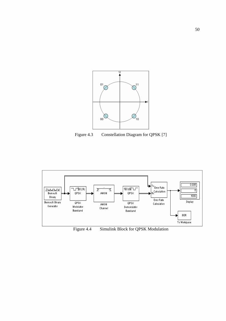
Sometimes known as quaternary or quadriphase PSK or 4-PSK, QPSK uses four
points on the constellation diagram, equispaced around a circle. With four phases,
QPSK can encode two bits per symbol, shown in the diagram with Gray coding to
minimize the BER twice the rate of BPSK. Analysis shows that this may be used either
to double the data rate compared to a BPSK system while maintaining the bandwidth of
the signal or to maintain the data-rate of BPSK but halve the bandwidth needed.
Although QPSK can be viewed as a quaternary modulation, it is easier to see it
as two independently modulated quadrature carriers. With this interpretation, the even
(or odd) bits are used to modulate the in-phase component of the carrier, while the odd
(or even) bits are used to modulate the quadrature-phase component of the carrier.
BPSK is used on both carriers and they can be independently demodulated.
50
Figure 4.3 Constellation Diagram for QPSK [7]
Figure 4.4 Simulink Block for QPSK Modulation
51
4.1.3 QPSK Modulation Using RoF
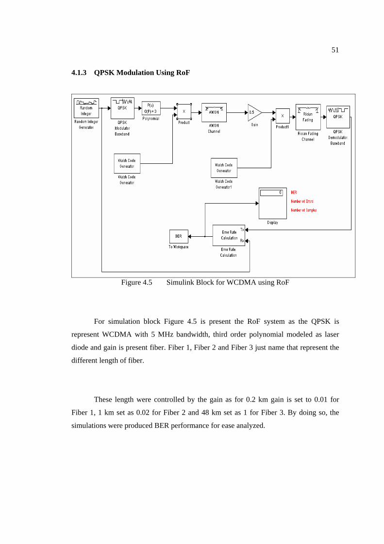
Figure 4.5 Simulink Block for WCDMA using RoF
For simulation block Figure 4.5 is present the RoF system as the QPSK is
represent WCDMA with 5 MHz bandwidth, third order polynomial modeled as laser
diode and gain is present fiber. Fiber 1, Fiber 2 and Fiber 3 just name that represent the
different length of fiber.
These length were controlled by the gain as for 0.2 km gain is set to 0.01 for
Fiber 1, 1 km set as 0.02 for Fiber 2 and 48 km set as 1 for Fiber 3. By doing so, the
simulations were produced BER performance for ease analyzed.
52
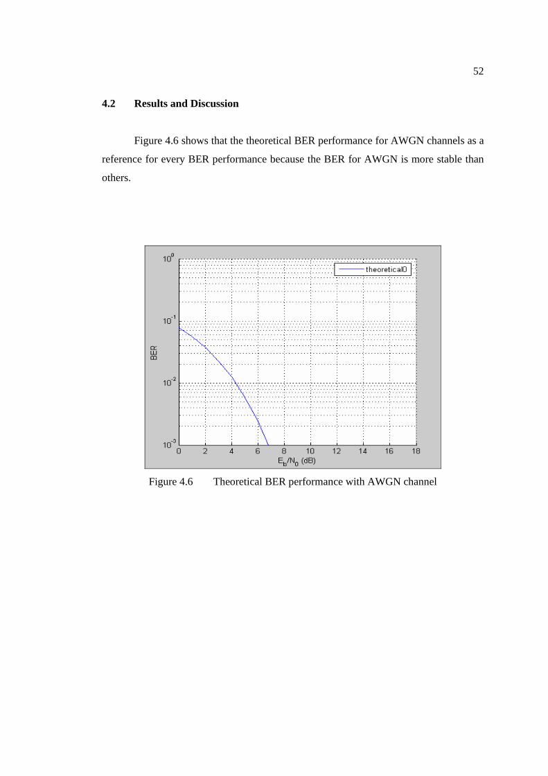
4.2 Results and Discussion
Figure 4.6 shows that the theoretical BER performance for AWGN channels as a
reference for every BER performance because the BER for AWGN is more stable than
others.
Figure 4.6 Theoretical BER performance with AWGN channel

53
Figure 4.7 shows the BER performance with AWGN channel by using BPSK
modulation. There is very similar with the BER performance for AWGN channel in
figure 4.6.
Figure 4.7 BER performance with AWGN channel for BPSK

54
Illustrate that shows BER performance for QPSK using AWGN channel as
Figure 4.8 is higher than BER performance for BPSK then.
Figure 4.8 BER performance with AWGN channel for QPSK

55
Figure 4.9 is shown the comparison between BER performance for BPSK and
BER performance for QPSK. For figure 4.10 shows both BER performance before
compare to theoretical BER performance.
Figure 4.9 Comparison BER of BPSK and QPSK
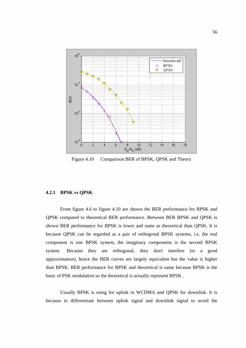
56
Figure 4.10 Comparison BER of BPSK, QPSK and Theory
4.2.1 BPSK vs QPSK
From figure 4.6 to figure 4.10 are shown the BER performance fro BPSK and
QPSK compared to theoretical BER performance. Between BER BPSK and QPSK is
shown BER performance for BPSK is lower and same as theoretical than QPSK. It is
because QPSK can be regarded as a pair of orthogonal BPSK systems, i.e. the real
component is one BPSK system, the imaginary components is the second BPSK
system. Because they are orthogonal, they don't interfere (to a good
approximation), hence the BER curves are largely equivalent but the value is higher
than BPSK. BER performance for BPSK and theoretical is same because BPSK is the
basic of PSK modulation so the theoretical is actually represent BPSK .
Usually BPSK is using for uplink in WCDMA and QPSK for downlink. It is
because to differentiate between uplink signal and downlink signal to avoid the
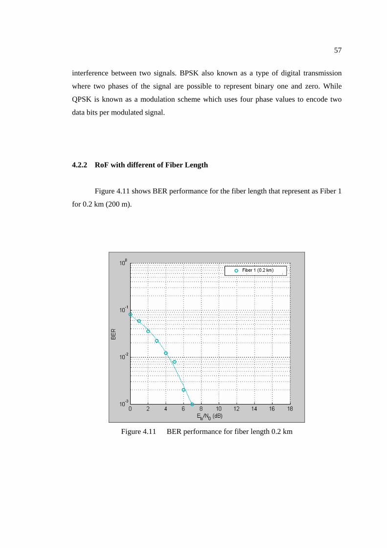
57
interference between two signals. BPSK also known as a type of digital transmission
where two phases of the signal are possible to represent binary one and zero. While
QPSK is known as a modulation scheme which uses four phase values to encode two
data bits per modulated signal.
4.2.2 RoF with different of Fiber Length
Figure 4.11 shows BER performance for the fiber length that represent as Fiber 1
for 0.2 km (200 m).
Figure 4.11 BER performance for fiber length 0.2 km
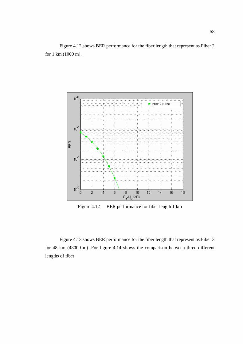
58
Figure 4.12 shows BER performance for the fiber length that represent as Fiber 2
for 1 km (1000 m).
Figure 4.12 BER performance for fiber length 1 km
Figure 4.13 shows BER performance for the fiber length that represent as Fiber 3
for 48 km (48000 m). For figure 4.14 shows the comparison between three different
lengths of fiber.
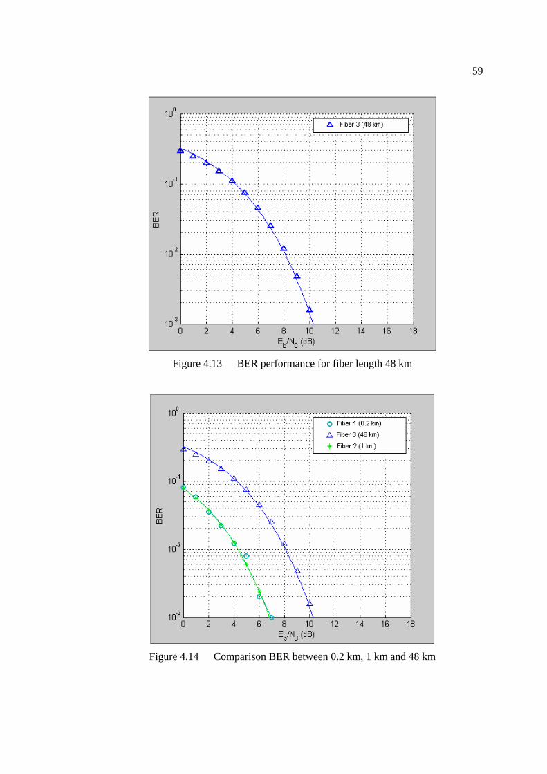
59
Figure 4.13 BER performance for fiber length 48 km
Figure 4.14 Comparison BER between 0.2 km, 1 km and 48 km
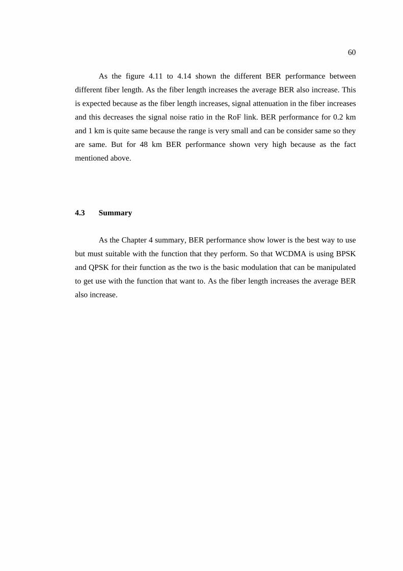
60
As the figure 4.11 to 4.14 shown the different BER performance between
different fiber length. As the fiber length increases the average BER also increase. This
is expected because as the fiber length increases, signal attenuation in the fiber increases
and this decreases the signal noise ratio in the RoF link. BER performance for 0.2 km
and 1 km is quite same because the range is very small and can be consider same so they
are same. But for 48 km BER performance shown very high because as the fact
mentioned above.
4.3 Summary
As the Chapter 4 summary, BER performance show lower is the best way to use
but must suitable with the function that they perform. So that WCDMA is using BPSK
and QPSK for their function as the two is the basic modulation that can be manipulated
to get use with the function that want to. As the fiber length increases the average BER
also increase.
61
CHAPTER 5
CONCLUSION AND SUGGESTIONS
5.1 Conclusion
As conclusion, the simulation of WCDMA Radio over fiber has been developed
successful. The BER performance shows the largest length is the largest BER measured.
The general concepts of WCDMA radio over fiber systems have been presented.
A simulation model of the downlink segment of a WCDMA radio over fiber system was
presented using Matlab simulink.
Combination of WCDMA and RoF represents a first demonstration of new
broadband applications using full radio over fiber environment. RoF will be suited to 3G
mobile networks due to the cost savings associated with providing many small cells
compared to conventional approaches. The input power and fiber length limits have
been established for WCDMA transmission and will not impose undue restrictions on
the use of RoF.

62
RoF has a very important role in cellular communications today and become
even more prevalent in the futures as more in-building systems are required. RoF
transmission technology needs to pay attention to the optical fiber length, the emission
wavelength of the laser & transmission frequency for RF signal (chromatic dispersion).
RoF network structure is more flexible & easy to expand when compared with
conventional network structures.
5.2 Suggestion For Future Research
The IEEE 802.11a standard is proposed for a range of data rates from 6 up to 54
Mbps using the OFDM modulation technique in the 5 GHz band. The 5 GHz band is
specifically designed for “Wireless Broadband Mobile Communication Systems
(WBMCS)”. The IEEE 802.11a WLAN standard is superior compared with current
technologies because of its greater scalability, better interference immunity and
significantly higher speed and at the same time allowing for higher bandwidth
applications and more users. The 802.11a standard utilizes 300 MHz of bandwidth in the
5 GHz unlicensed National Information Infrastructure (U-NII) band.
Orthogonal Frequency Division Multiplexing (OFDM) is seen as the modulation
technique for future broadband wireless communications because its provides increased
robustness against frequency selective fading and narrowband interference and is
efficient in dealing with multi-path delay spread. To achieve this, OFDM splits high-rate
data streams into lower rate streams, which are then transmitted simultaneously over
several sub-carriers. By doing so, the symbol duration is increased.
OFDM uses multiple sub-carriers to transmit low rate data streams in parallel.
The sub-carriers are modulated by using Phase Shift Keying (PSK) or Quadrature

63
Amplitude Modulation (QAM) and are then carried on a high frequency microwave
carrier such as 5 GHz.

64
REFERENCES
1. Hamed Al-Raweshidy and Shozo Komaki Radio Over Fiber Technologies For
Mobile Communication Network. 1st edition. Universal Personal
Communication, Norwood, MA: Artech House Publishers. 2002.
2. Stephen Z. Pinter and Xavier N. Fernando. Fiber-Wireless Solution for
Broadband Multimedia Access. Ryerson University, Toronto, ON.
3. Harri Holma and Antti Toskala. WCDMA for UMTS-Radio Access For Third
Generation Mobile Communication; John Wiley & Sons,Ltd. 2001
4. J. S. Wu, J Wu and H W Tsao. A Radio-over-Fibre Network for Microcellular
System application. IEEE Trans. on Vehicular Technology. February 1998. Vol.
47. No. 1
5. Nazem Khashjori and H.S. Al-Raweshidy. Capacity Improvement in the
Downlink of WCDMA with Radio over Fibre Access Network. University of
Kent, UK.
6. Cooper, A.J. Fiber-Radio for the Provision of Cordless/Mobile Telephony
Services in the Access Network. Electron. Lett., Vol. 26. 1990. 2054-2056
7. Stephen Z. Pinter and Xavier N. Fernando. Fiber-Wireless Solution for Road and
Multimedia Access. Ryerson University, Toronto, ON.
8. P. K. Tang, L. C. Ong, B. Luo, A. Alphones, and M. Fujise, Òtransmission of
Multiple Wireless Standards over a Radio-over-fiber Network. Proceedings of
the IEEE TT-S International Microwave Symposium Digest. June 2004.Vol. 3.
2051-2054.
9. Xavier N. Fernando and Abu B. Sesay. Adaptive Asymmetric Linearization of
Radio Over Fiber Links for wireless Access. IEEE Trans. on Vehicular
Technology. November 2002.Vol. 51. No. 6, 1578.
10. X. N. Fernando and S. Z.Pinter. Radio over Fiber for Broadband Wireless
Access. ADROIT Group, Ryerson University, Toronto, ON M5B 2K3, Canada.
11. István Frigyes. Radio Over Fiber: Application, Basic Design and Impact on
Resource Management. Budapest University of Technology and Economics.
65
12. H.S. Al-Raweshidy and S.O. Ampem-Darko. WCDMA-Based Radio over Fibre
System Performance with Multiple-User Interference in Multiple Service
Transmission. University of Kent, UK. March 2001. 152-155.
13. Tsutomu Niiho, Mariko Nakaso, Koichi Masuda, Hiroyuki Sasai, Kuniaki
Utsumi and Masaru Fuse. Transmission Performance of Multichannel Wireless
LAN System Based on Radio Over Fiber Techniques. IEEE Trans. on
Microwave Theory and Techniques, February 2006 February 2006. Vol. 54. No.
2. 980-988.
14. Gurprakash Singh and Arokiaswami Alphones. OFDM Modulation Study for
Radio-over-Fiber System for Wireless LAN (IEEE 802.11a). Nanyang
Technological University, Singapore. 15-18 December 2003.1460-1464.
15. Nazem Khashjori and H.S. Al-Raweshidy. System Level Performance of
WCDMA With Radio Over Fibre Access Network. University of Kent, UK.
Top Related