


Languages
Pages
Legal


Ignition Timing Accuracy : Causes, Impact, and Solutions Presented by: Fred Husher
12/9-10/2014 1
Assuming the engine is capable of perfect performance:
Ignition system performance is limited by the cumulative errors:
mechanical elements, sensors, and signal processing
cranecams.com
12/9-10/2014 2
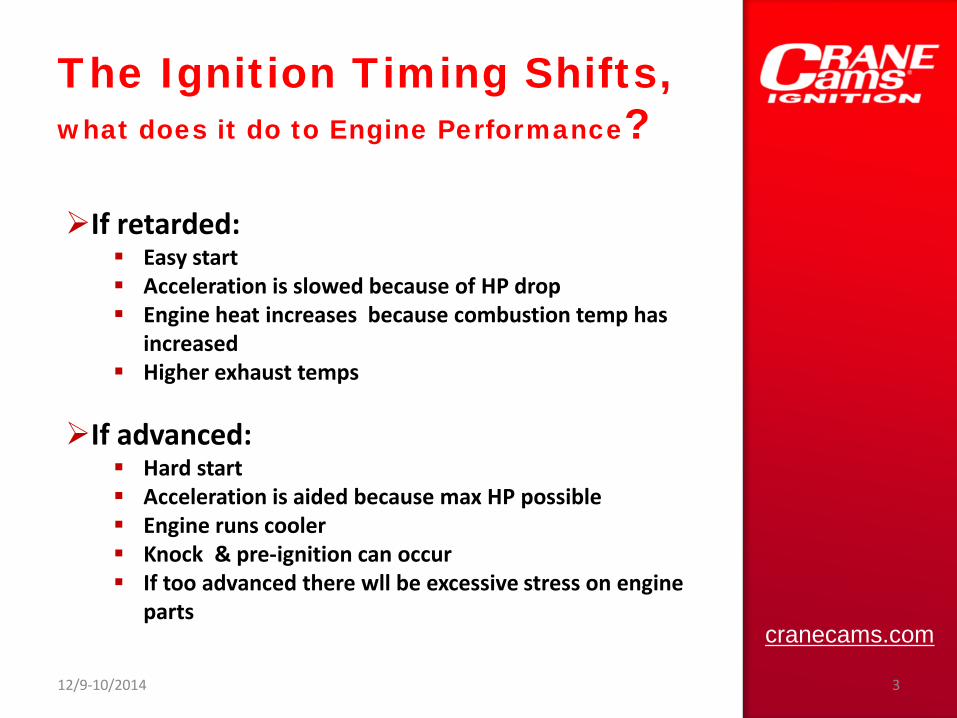
The Ignition Timing Shifts, what does it do to Engine Performance? If retarded:
Easy start Acceleration is slowed because of HP drop Engine heat increases because combustion temp has
increased Higher exhaust temps
If advanced: Hard start Acceleration is aided because max HP possible Engine runs cooler Knock & pre-ignition can occur If too advanced there wll be excessive stress on engine
parts
cranecams.com
12/9-10/2014 3
cranecams.com
12/9-10/2014 4
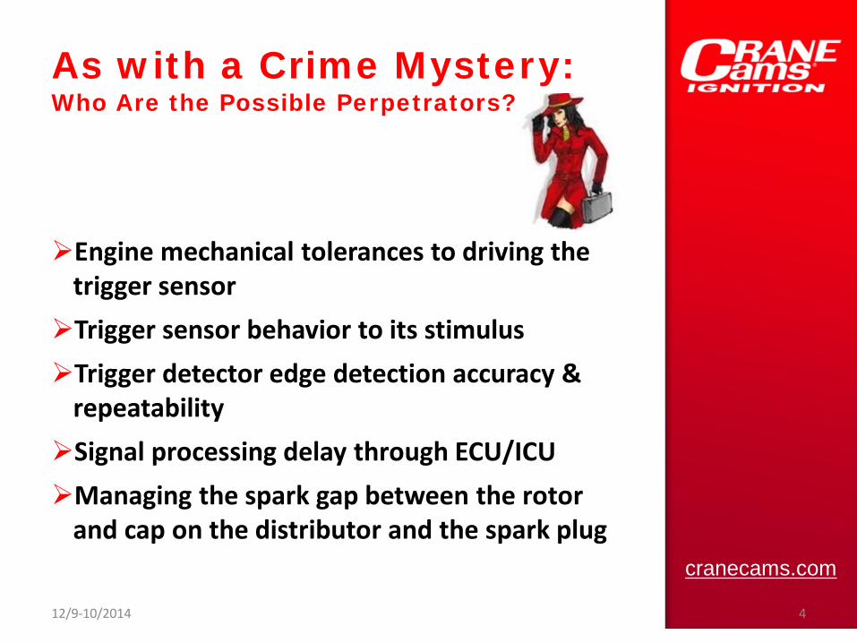
As with a Crime Mystery: Who Are the Possible Perpetrators?
Engine mechanical tolerances to driving the trigger sensor Trigger sensor behavior to its stimulus Trigger detector edge detection accuracy & repeatability Signal processing delay through ECU/ICU Managing the spark gap between the rotor and cap on the distributor and the spark plug

The focus of this discussion will be on: trigger sensor, sensor signal processing and their mechanical supporting elements
12/9-10/2014 5

The mechanical causes are often the easier to identify: Distributor
Shaft end play shifts timing • CW: advance on acceleration • CCW: retard on acceleration
Rotational wobble causes timing bobble between cylinders
Backlash between cam & distributor gears Mismatch of advance springs & weights to cam, if
used Cam Shaft
End play imposes timing shift to the distributor Crankshaft
Torque can move crank timing disk and change the trigger timing
cranecams.com
12/9-10/2014 6
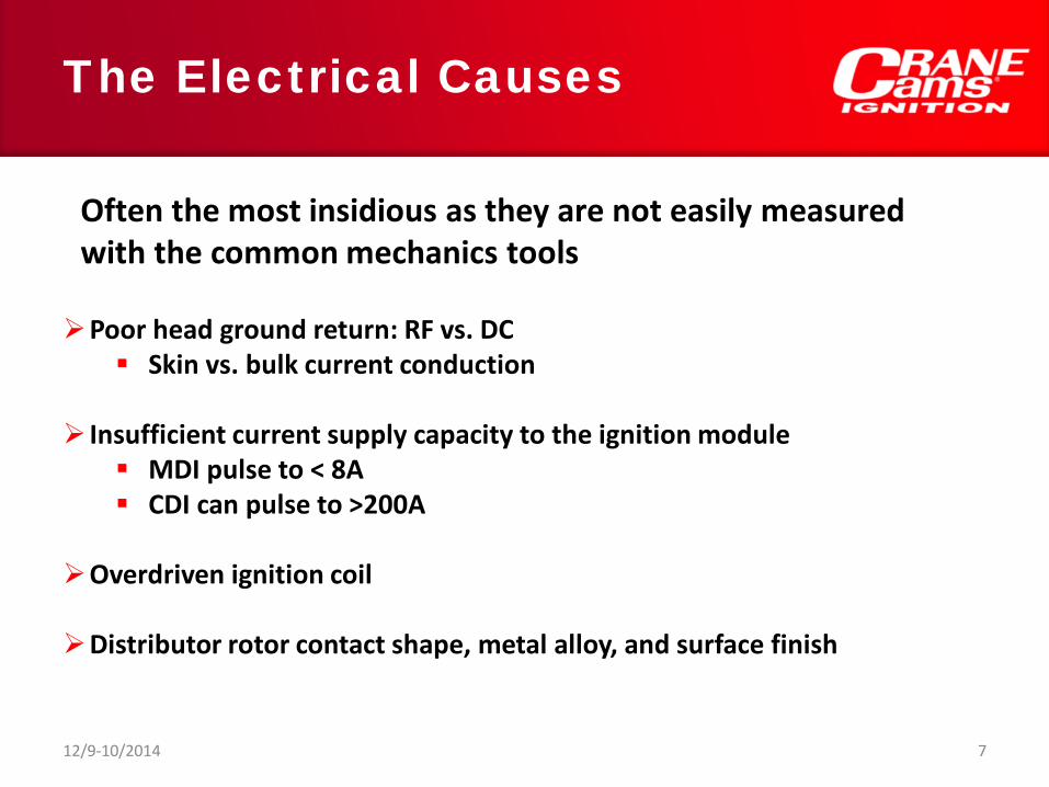
The Electrical Causes
Poor head ground return: RF vs. DC Skin vs. bulk current conduction
Insufficient current supply capacity to the ignition module MDI pulse to < 8A CDI can pulse to >200A
Overdriven ignition coil
Distributor rotor contact shape, metal alloy, and surface finish
Often the most insidious as they are not easily measured with the common mechanics tools
12/9-10/2014 7
Trigger Sensor Behavior to its Stimulus & Environment
Mechanical motion variations Temperature: magnetic or optical Induced EMI to signal lines Ground loop currents such as spark return Load dump sensitivity from solenoid release Battery voltage sag and failure to/from alternator, battery, & ignition module
cranecams.com
12/9-10/2014 8
The input signal type has considerable impact on how it can be processed Variable Reluctor coil Digital (open drain/collector) Hall Effect Opto-interrupter sensors
Digital or analog variable reluctor mimics RS-232 output – Crane Pro-Race distributor Capacitor coupled outputs – Crane Race Billet
distributor Differential RC outputs – Crane Crank Sensor
The exotics: magnetostrictive, piezoelectric, and Wiegand
12/9-10/2014 9

cranecams.com
12/9-10/2014 10
Variable Reluctor Coil
Developed voltage by the VR is Voltage developed = N(ΔΦ/Δt),
Attributes: Unable to function at slow RPMs Noise immune with differential detector Noise sensitive with single ended detector Rise/falling trigger edge choice is by simply
exchanging the coil’s leads, MAG+ & MAG- Fragile due to the coil’s wire winding breaking from vibration
From US6278496

cranecams.com
Digital Attributes Dominated by open drain/collector output Types Hall Effect Opto-interrupter sensors
Output low is limited to Vsat ~ 0.2V
12/9-10/2014 11
Opto-interrupter Triggers
12/9-10/2014 12
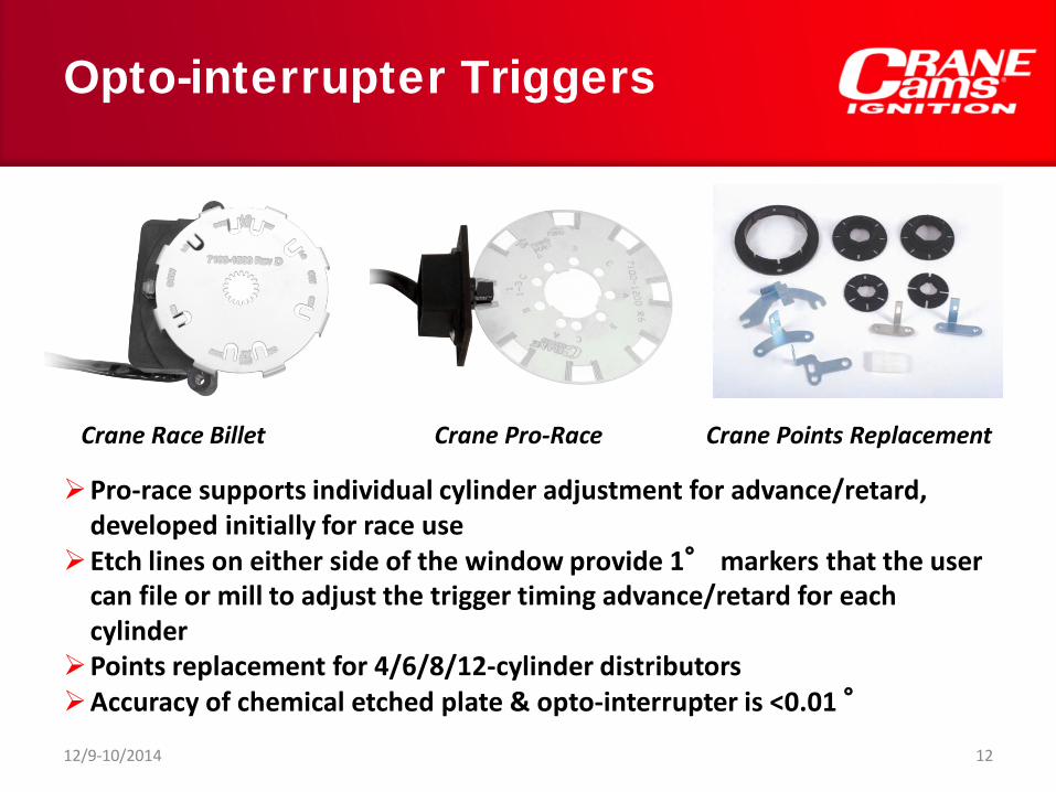
Pro-race supports individual cylinder adjustment for advance/retard, developed initially for race use Etch lines on either side of the window provide 1° markers that the user can file or mill to adjust the trigger timing advance/retard for each cylinder Points replacement for 4/6/8/12-cylinder distributors Accuracy of chemical etched plate & opto-interrupter is <0.01 °
Crane Race Billet Crane Pro-Race Crane Points Replacement
cranecams.com
12/9-10/2014 13
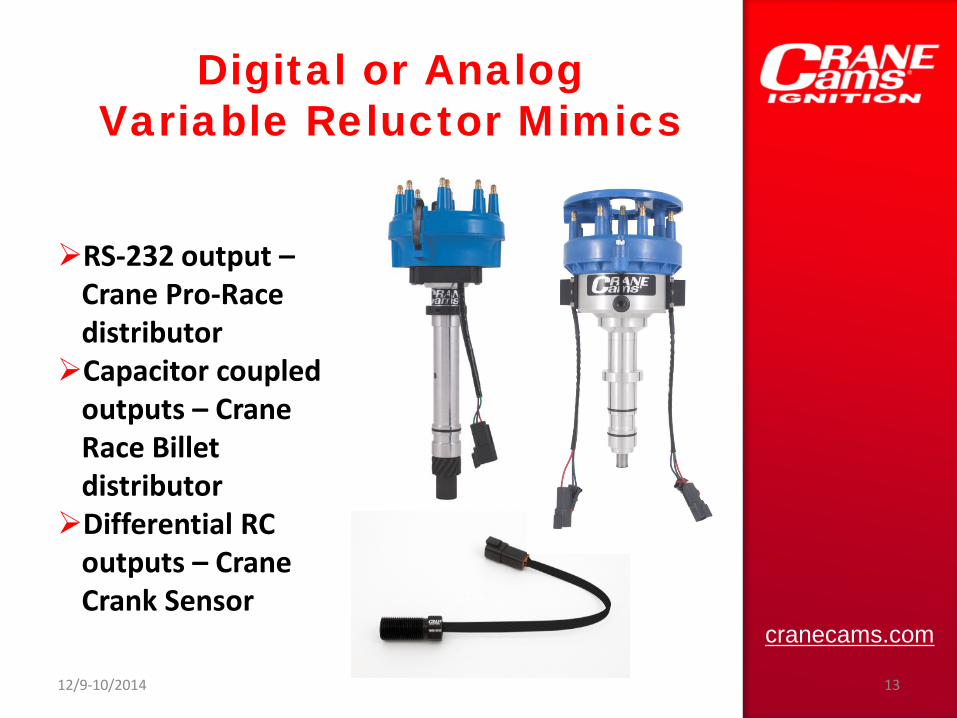
Digital or Analog Variable Reluctor Mimics
RS-232 output – Crane Pro-Race distributor Capacitor coupled outputs – Crane Race Billet distributor Differential RC outputs – Crane Crank Sensor

Variable Reluctor Mimic: RS-232 Output
12/9-10/2014 14
Single ended output +/- 7 to 10V output swing Very high noise immunity to VR trigger detector
Signal never at 0V Low output impedance
GNDMAG+
U105MAX3232
V
I O
G
+5V +12V
+IGN
CON3
123
Simplified circuit
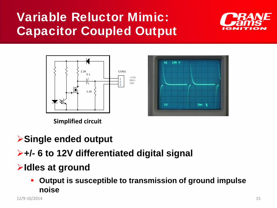
Variable Reluctor Mimic: Capacitor Coupled Output
12/9-10/2014 15
Single ended output +/- 6 to 12V differentiated digital signal Idles at ground
Output is susceptible to transmission of ground impulse noise
2.2K
2.2K
MAG++IGN
GND
0.1CON3
123
Simplified circuit

Variable Reluctor Mimic Differential RC Coupled Output
12/9-10/2014 16
Differential output signaling MAG + & MAG- can be swapped just as with the VR sensor to change
trigger edge Either output can be shorted to ground Output signals can be floated to +2.5V to support use with single supply differential input detectors Very high noise immunity rejection into VR trigger detector
+5V
R242.4K
R252.4K
R264.7K
U3ISL3294EFHZ-T
V2
G5
A6
B4
DI1
DE3
R271K
R284.7K
U6HALL SENSOR
V+1
G2
O3
+C41UF/16V
+
C31UF/16V
SIMPLIFIED DIFFERENTIALOUTPUT HALL SENSOR
MAG-
MAG+

cranecams.com
12/9-10/2014 17
Hall Sensor Attributes
Uni-polar Hall sensor Operational to zero RPM Rugged and stable throughout -40 to
+125°C Not usable with VR detectors without
signal conversion
The developed signal is independent of any rate of change in the magnetic field acting upon the Hall Effect bridge
cranecams.com
12/9-10/2014 18
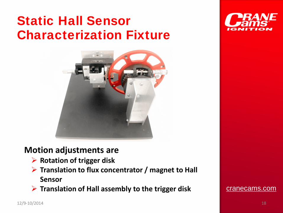
Static Hall Sensor Characterization Fixture
Motion adjustments are Rotation of trigger disk Translation to flux concentrator / magnet to Hall
Sensor Translation of Hall assembly to the trigger disk
cranecams.com
12/9-10/2014 19
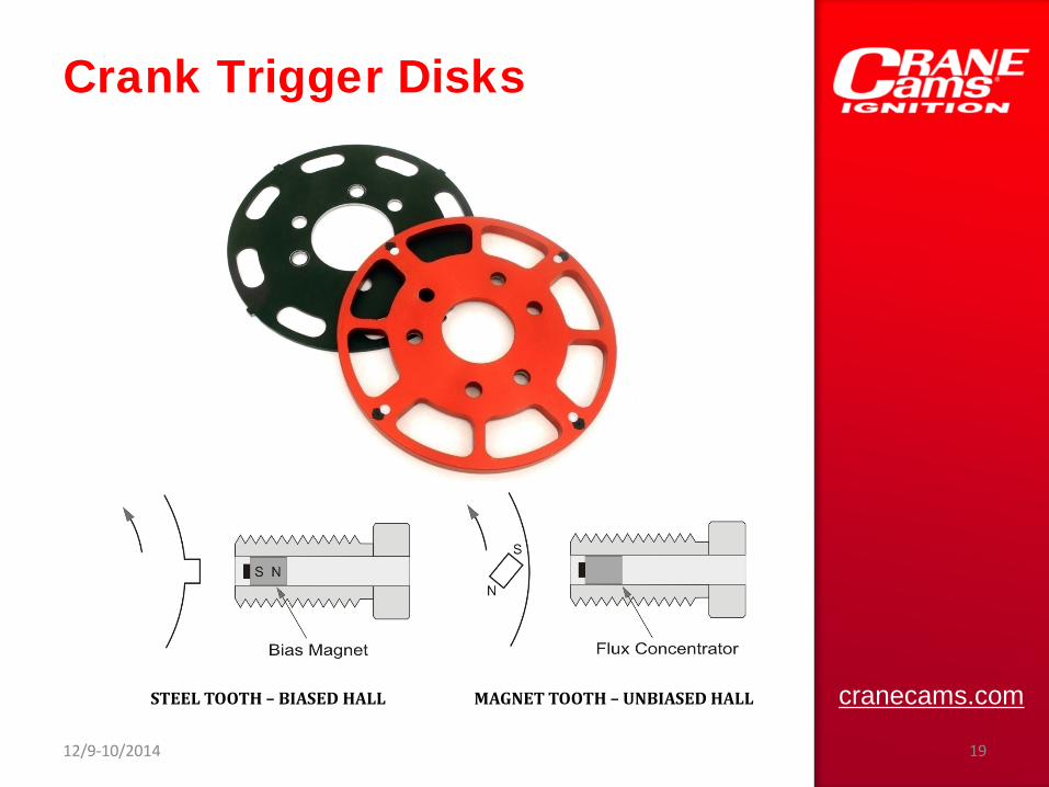
Crank Trigger Disks
STEEL TOOTH – BIASED HALL MAGNET TOOTH – UNBIASED HALL
Crank Trigger Disks
Magnetic Circuit Iron core flux concentrator for embedded magnet trigger disks
• Embedded magnets are matched for flux density Back biased sensor with integral magnet for steel tooth trigger disks
Timing accuracy depends on all teeth being of Equal geometry & spacing Width, slope, and gap distance Tooth shape to optimize the magnetic field state change
For embedded magnet disks The magnets are tilted relative to axis of rotation by 45-50° to
accelerate the field collapse in the variable reluctor sensor core
12/9-10/2014 20

Trigger Disk Eccentricity
Changes in gap distance = changes in flux density Variable Reluctor Sensor Gap change = amplitude modulation of the developed coil voltage.
Fixed threshold detectors are mostly unaffected Adaptive threshold detectors using (amplitude * rate-of-change)
are sensitive to gap modulation, but the jitter will be below 0.05°
Hall Effect Sensor Gap change = change in when flux threshold levels are passed
Fixed threshold & adaptive threshold Hall sensors react differently
12/9-10/2014 21
Trigger Disk Eccentricity
Hall Sensor with Fixed Threshold Sees a change in gap as a change in flux density >> timing shift
Hall switch sensors incorporate their own threshold detectors • Therefore, a change in gap will translate to a rotational shift • This will be a linear relationship less than a 0.02°total impact.
Tooth shape will play a role in how sensitive this will be.
Hall Sensor with Adaptive Threshold Uses each peak to set the next threshold level. Even with a 20% change in
gap distance the change in phase delay is insignificant.
12/9-10/2014 22
cranecams.com
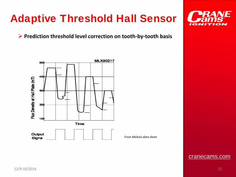
Adaptive Threshold Hall Sensor
From Melexis data sheet
Prediction threshold level correction on tooth-by-tooth basis
12/9-10/2014 23
cranecams.com
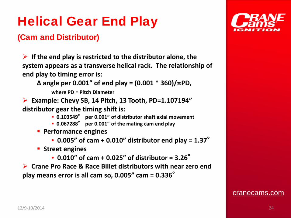
Helical Gear End Play (Cam and Distributor)
If the end play is restricted to the distributor alone, the system appears as a transverse helical rack. The relationship of end play to timing error is:
Δ angle per 0.001” of end play = (0.001 * 360)/πPD, where PD = Pitch Diameter
Example: Chevy SB, 14 Pitch, 13 Tooth, PD=1.107194” distributor gear the timing shift is:
0.103549° per 0.001” of distributor shaft axial movement 0.067288° per 0.001” of the mating cam end play
Performance engines • 0.005” of cam + 0.010” distributor end play = 1.37°
Street engines • 0.010” of cam + 0.025” of distributor = 3.26°
Crane Pro Race & Race Billet distributors with near zero end play means error is all cam so, 0.005” cam = 0.336°
12/9-10/2014 24
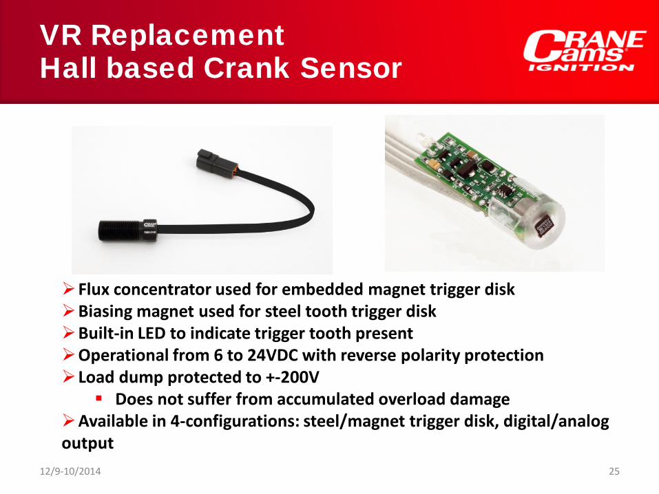
VR Replacement Hall based Crank Sensor
12/9-10/2014 25
Flux concentrator used for embedded magnet trigger disk Biasing magnet used for steel tooth trigger disk Built-in LED to indicate trigger tooth present Operational from 6 to 24VDC with reverse polarity protection Load dump protected to +-200V
Does not suffer from accumulated overload damage Available in 4-configurations: steel/magnet trigger disk, digital/analog output

Trigger Detector Edge Detection Accuracy & Repeatability
Every trigger detector consists of: Input signal conditioning Protection from excessive input signals
Translation between the sensor signal and the digital needs within the ignition/fuel injection control modules Analog comparator which introduces delay in
recognizing a state change: <1usec
12/9-10/2014 26

Digital – Points Detector
+3.3V
S1POINTS
ISO1OPTO IINTERRUPTER390
+IGN
DIGITAL INPUT
OUT#
OUT#
D8 D9100
4.7K220K
15K
47K
-
+
LM29033
21
84
+15V+5V
+IGN
TRIG
Protected against shorts to ground, +Vbatt, or load dump signals Sensor Vsat up to +4V is acceptable
Very high ground noise rejection Insignificant timing delay over all RPM
Typical points/digital input detector
Digital trigger
Points
12/9-10/2014 27

Variable Reluctor Detector Circuits
Fixed threshold Single ended Differential
Adaptive threshold
Single ended Differential
cranecams.com
12/9-10/2014 28
cranecams.com
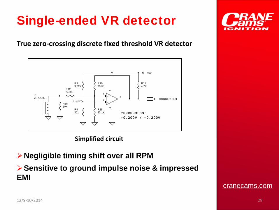
Single-ended VR detector
Negligible timing shift over all RPM Sensitive to ground impulse noise & impressed EMI
-
+3
21
84
R8301
R99.82K
R10301K
R114.7K
R1224.3K
R1510K
+0.226V
THRESHOLDS:+0.200V / -0.200V
+5V
TRIGGER OUTL1VR COIL
R3893.1K
True zero-crossing discrete fixed threshold VR detector
Simplified circuit
12/9-10/2014 29

cranecams.com
Adaptive Threshold VR Detector
Threshold level changes with signal amplitude and RPM Unable to cope with constant amplitude input without serious timing retard error vs. RPM Sensitive to ground impulse noise and impressed EMI
Example of TI LM1815 implementation
C130.01
R3620K
R373.16K
SIMPLIFIED LM1815 IN ADAPTIVE TRIGGER MODE
PEAKDETECTOR
TRIGGER OUT
-
+3
21
-
+5
67-
+3
21
C110.1
C120.001
R341M
ONE-SHOT
R35182K
+5V
RC
QTRIG
L2VR COIL
12/9-10/2014 30

cranecams.com
Differential VR Trigger Detector
Inputs are floated to +2.5V True zero-crossing detection largely independent of signal amplitude CMRR ensures all impressed EMI is rejected Not affected by ground noise
Maxim MAX9924-9927 family are the only integrated differential input detectors
12/9-10/2014 31
MAX9924 With external support detector can be configured to support:
VR Digital/points All VR mimics
Both adaptive and fixed threshold modes are supported With suitable stimulus, measurement, and control the sensor can be identified causing the MAX9924 to be configured for optimal support and processing of the sensor’s signal
cranecams.com
12/9-10/2014 32
cranecams.com
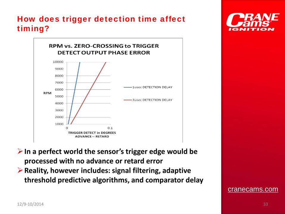
How does trigger detection time affect timing?
In a perfect world the sensor’s trigger edge would be processed with no advance or retard error Reality, however includes: signal filtering, adaptive threshold predictive algorithms, and comparator delay
12/9-10/2014 33

Dynamic Characterization of Hall & VR Sensors
12/9-10/2014 34
Crank sensor to trigger wheel gap can be adjusted as in vehicle Spindle can be set from static to 10,000 RPM Sensor gap can be adjusted to centerline of trigger disk with X & Y adjustments

1000
2000
3000
4000
5000
6000
7000
8000
9000
10000
-80 -70 -60 -50 -40 -30 -20 -10 0 10 20 30 40 50 60 70 80
RPM
TRIGGER DETECT in usec ADVANCE -- RETARD
RPM vs. ZERO-CROSSING to DETECTOR OUTPUT TIME
Crane HI6 - CRANK SENSOR
CRANE HI6 - VR SENSOR
LM1815 - CRANE CRANK SENSOR
LM1815 - VR SENSOR
MAX9924 - CRANE CRANK SENSOR
MAX9924 - VR SENSOR
COMPETITOR - CRANE CRANKSENSOR
COMPETITOR - VR SENSOR
Detector – Sensor Results For a 0.080” sensor – disk gap
12/9-10/2014 35

Detector – Sensor Results For a 0.080” sensor – disk gap
1000
2000
3000
4000
5000
6000
7000
8000
9000
10000
-0.3 -0.2 -0.1 0 0.1 0.2 0.3 0.4 0.5
RPM
TRIGGER DETECT in DEGREES ADVANCE -- RETARD
RPM vs. ZERO-CROSSING to TRIGGER DETECT OUTPUT PHASE ERROR
CRANE HI6 - CRANK SENSOR
CRANE HI6 -- VR SENSOR
LM1815 - CRANE CRANK SENSOR
LM1815 - VR SENSOR
MAX9924 - CRANE CRANK SENSOR
MAX9924 - VR SENSOR
COMPETITOR - CRANE CRANKSENSOR
COMPETITOR - VR SENSOR
12/9-10/2014 36
cranecams.com
12/9-10/2014 37
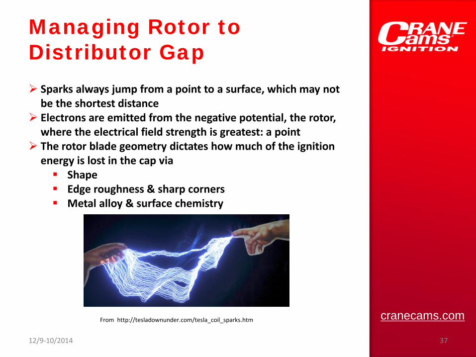
Managing Rotor to Distributor Gap Sparks always jump from a point to a surface, which may not be the shortest distance Electrons are emitted from the negative potential, the rotor, where the electrical field strength is greatest: a point The rotor blade geometry dictates how much of the ignition energy is lost in the cap via
Shape Edge roughness & sharp corners Metal alloy & surface chemistry
From http://tesladownunder.com/tesla_coil_sparks.htm

cranecams.com
12/9-10/2014 38
Managing Rotor to Distributor Gap
Increased spark length = energy wasted as heat to maintain plasma
The stator contact should be curved to reduce the spark gap distance throughout the spark duration(s)
Cutting back the trailing edge of the rotor blade ensures the next is the shortest path
If the spark is unable to slide along the edge of the rotor blade then the spark duration will be cut short If the preferred launch point to stator is too far, timing will be retarded
Ignition Wiring Spark event in cylinder is really a RF transmitter within a metal container RF energy only flows on metal surfaces Braided straps provide the low RF impedance path for spark current between
Head(s) to block Block to ignition ground. The head bolts
do not conduct the spark current even though they measure as a DC short circuit.
CDI recharge demands are at low RF frequencies that demand both DC & RF wiring considerations
cranecams.com
12/9-10/2014 39

Sensor Wiring Any connection of a sensor ground to the engine provides a pathway for ground loop currents to the measurement circuit EMI can be impressed upon any single-ended sensor signal EMI cannot be impressed upon a differential sensor signal as it will be common mode rejected on receipt Twisted pair or triad ensures that all leads get the same EMI exposure
cranecams.com
12/9-10/2014 40

cranecams.com
Sensor Wiring
If load 1 = load 2 then Voltmeter M1 is > Voltmeter M2 because of the addition of 2R more sheet resistance in the head Thus, spark currents will change the ground potential spatially depending upon the position and path to ground
BT112V BATTERY
LOAD-1
R R R R R
ENGINE HEAD
A-
+ M1VOLTMETER
A-
+ M2VOLTMETER
LOAD-2
12/9-10/2014 41
Closing
Ignition triggering accuracy can be well within 0.1 degree of accuracy over all RPM by choice of trigger sensor, measurement site, trigger signal detector circuit, and distributor Differential signal processing rejects EMI and ground loop currents since only the difference is considered Very valuable in noisy engine environments
Treatment of grounding from a RF basis will greatly reduce the radiation of EMI signals
12/9-10/2014 42

cranecams.com
12/9-10/2014 43
Top Related