


Languages
Pages
Legal


FlexiHybrid
IDU HW Install
A25000-A0300-F031-02-76P1
Issue: 2 Issue date: January 2010
2 A25000-A0300-F031-02-76P1Issue: 2 Issue date: January 2010
IDU HW Install
The information in this document is subject to change without notice and describes only the product defined in the introduction of this documentation. This documentation is intended for the use of Nokia Siemens Networks customers only for the purposes of the agreement under which the document is submitted, and no part of it may be used, reproduced, modified or transmitted in any form or means without the prior written permission of Nokia Siemens Networks. The documentation has been prepared to be used by professional and properly trained personnel, and the customer assumes full responsibility when using it. Nokia Siemens Networks welcomes customer comments as part of the process of continuous development and improvement of the documentation.
The information or statements given in this documentation concerning the suitability, capacity, or performance of the mentioned hardware or software products are given "as is" and all liability arising in connection with such hardware or software products shall be defined conclusively and finally in a separate agreement between Nokia Siemens Networks and the customer. However, Nokia Siemens Networks has made all reasonable efforts to ensure that the instructions contained in the document are adequate and free of material errors and omissions. Nokia Siemens Networks will, if deemed necessary by Nokia Siemens Networks, explain issues which may not be covered by the document.
Nokia Siemens Networks will correct errors in this documentation as soon as possible. IN NO EVENT WILL NOKIA SIEMENS NETWORKS BE LIABLE FOR ERRORS IN THIS DOCUMEN-TATION OR FOR ANY DAMAGES, INCLUDING BUT NOT LIMITED TO SPECIAL, DIRECT, INDIRECT, INCIDENTAL OR CONSEQUENTIAL OR ANY LOSSES, SUCH AS BUT NOT LIMITED TO LOSS OF PROFIT, REVENUE, BUSINESS INTERRUPTION, BUSINESS OPPORTUNITY OR DATA,THAT MAY ARISE FROM THE USE OF THIS DOCUMENT OR THE INFORMATION IN IT.
This documentation and the product it describes are considered protected by copyrights and other intellectual property rights according to the applicable laws.
The wave logo is a trademark of Nokia Siemens Networks Oy. Nokia is a registered trademark of Nokia Corporation. Siemens is a registered trademark of Siemens AG.
Other product names mentioned in this document may be trademarks of their respective owners, and they are mentioned for identification purposes only.
Copyright © Nokia Siemens Networks 2010. All rights reserved.
f Important Notice on Product SafetyElevated voltages are inevitably present at specific points in this electrical equipment. Some of the parts may also have elevated operating temperatures.
Non-observance of these conditions and the safety instructions can result in personal injury or in property damage.
Therefore, only trained and qualified personnel may install and maintain the system.
The system complies with the standard EN 60950 / IEC 60950. All equipment connected has to comply with the applicable safety standards.
The same text in German:
Wichtiger Hinweis zur Produktsicherheit
In elektrischen Anlagen stehen zwangsläufig bestimmte Teile der Geräte unter Span-nung. Einige Teile können auch eine hohe Betriebstemperatur aufweisen.
Eine Nichtbeachtung dieser Situation und der Warnungshinweise kann zu Körperverlet-zungen und Sachschäden führen.
Deshalb wird vorausgesetzt, dass nur geschultes und qualifiziertes Personal die Anlagen installiert und wartet.
Das System entspricht den Anforderungen der EN 60950 / IEC 60950. Angeschlossene Geräte müssen die zutreffenden Sicherheitsbestimmungen erfüllen.
A25000-A0300-F031-02-76P1Issue: 2 Issue date: January 2010
3
IDU HW Install
Table of ContentsThis document has 90 pages.
1 Preface . . . . . . . . . . . . . . . . . . . . . . . . . . . . . . . . . . . . . . . . . . . . . . . . . . 91.1 Intended audience . . . . . . . . . . . . . . . . . . . . . . . . . . . . . . . . . . . . . . . . . . 91.2 Structure of this document . . . . . . . . . . . . . . . . . . . . . . . . . . . . . . . . . . . . 91.3 Symbols and conventions . . . . . . . . . . . . . . . . . . . . . . . . . . . . . . . . . . . . 91.4 History of changes . . . . . . . . . . . . . . . . . . . . . . . . . . . . . . . . . . . . . . . . . 111.5 Waste electrical and electronic equipment (WEEE) . . . . . . . . . . . . . . . 111.6 RoHS compliance . . . . . . . . . . . . . . . . . . . . . . . . . . . . . . . . . . . . . . . . . 11
2 ETSI rack installation . . . . . . . . . . . . . . . . . . . . . . . . . . . . . . . . . . . . . . . 132.1 View of the ETSI rack . . . . . . . . . . . . . . . . . . . . . . . . . . . . . . . . . . . . . . 132.2 Drilling planes . . . . . . . . . . . . . . . . . . . . . . . . . . . . . . . . . . . . . . . . . . . . 142.2.1 In-line installation of the Rack ETSI without combining frame. . . . . . . . 142.2.2 Back-to-back installation of the Rack ETSI without combining frame . . 162.2.3 Wall mounting the Rack ETSI without combining frame . . . . . . . . . . . . 182.2.4 In-line installation of the Rack ETSI without combining frame on floating
floor or on wall . . . . . . . . . . . . . . . . . . . . . . . . . . . . . . . . . . . . . . . . . . . . 182.2.5 Back-to-back installation of the Rack ETSI without combining frame on
floating floor . . . . . . . . . . . . . . . . . . . . . . . . . . . . . . . . . . . . . . . . . . . . . . 202.2.6 Characteristics and installation procedure of the self-locking bolts for floors
212.2.7 Characteristics and installation procedure of the expansion bolts for walls
222.3 Connections. . . . . . . . . . . . . . . . . . . . . . . . . . . . . . . . . . . . . . . . . . . . . . 232.3.1 Ground connections for the rack ETSI. . . . . . . . . . . . . . . . . . . . . . . . . . 23
3 IDU installation. . . . . . . . . . . . . . . . . . . . . . . . . . . . . . . . . . . . . . . . . . . . 243.1 IDU installation in the ETSI rack . . . . . . . . . . . . . . . . . . . . . . . . . . . . . . 243.2 External connections . . . . . . . . . . . . . . . . . . . . . . . . . . . . . . . . . . . . . . . 243.2.1 Primary supply voltage connection (Power supply unit P/N 611-526/70) 253.2.2 Controller (P/N 634-001/81) and Controller2 (P/N 634-001/91) Unit . . . 263.2.2.1 Network Management System Ethernet connections. . . . . . . . . . . . . . . 263.2.2.2 Alarms/Serial connection . . . . . . . . . . . . . . . . . . . . . . . . . . . . . . . . . . . . 263.2.2.3 USB Connection (future use) . . . . . . . . . . . . . . . . . . . . . . . . . . . . . . . . . 273.2.3 Standard (P/N 612-315/01), Standard2 (P/N 612-315/37), Enhanced (P/N
612-315/15) and Enhanced2 (P/N 612-315/39) Master I/O unit . . . . . . 283.2.3.1 Ethernet Connection (User Data Payload). . . . . . . . . . . . . . . . . . . . . . . 283.2.3.2 E1 channel 1 and 2 connections . . . . . . . . . . . . . . . . . . . . . . . . . . . . . . 293.2.3.3 3 to 16 channel E1 connections. . . . . . . . . . . . . . . . . . . . . . . . . . . . . . . 303.2.3.4 Voice Orderwire connection. . . . . . . . . . . . . . . . . . . . . . . . . . . . . . . . . . 353.2.3.5 DATA Orderwire connection . . . . . . . . . . . . . . . . . . . . . . . . . . . . . . . . . 363.2.4 16 E1 Expansion I/O Unit (P/N 612-315/05) . . . . . . . . . . . . . . . . . . . . . 373.2.4.1 E1 channel 1 and 2 connections . . . . . . . . . . . . . . . . . . . . . . . . . . . . . . 373.2.4.2 3 to 16 channel E1 connections. . . . . . . . . . . . . . . . . . . . . . . . . . . . . . . 383.2.5 42xE1 Master I/O unit (P/N 612-315/03) . . . . . . . . . . . . . . . . . . . . . . . . 443.2.5.1 Ethernet Connection (User Data Payload). . . . . . . . . . . . . . . . . . . . . . . 443.2.5.2 1 to 14 / 15 to 28 / 29 to 42 channel E1 connections. . . . . . . . . . . . . . . 46
4 A25000-A0300-F031-02-76P1Issue: 2 Issue date: January 2010
IDU HW Install
3.2.5.3 Voice Orderwire connection . . . . . . . . . . . . . . . . . . . . . . . . . . . . . . . . . . 513.2.5.4 DATA Orderwire connection . . . . . . . . . . . . . . . . . . . . . . . . . . . . . . . . . . 523.2.6 21xE1 Expansion I/O Unit (P/N 612-315/06) . . . . . . . . . . . . . . . . . . . . . 533.2.6.1 1 to 14 / 15 to 21 channel E1 connections . . . . . . . . . . . . . . . . . . . . . . . 543.2.7 Gigabit Ethernet (P/N 612-315/10) and Gigabit Enhanced Ethernet (P/N
612-315/16) Master I/O Unit . . . . . . . . . . . . . . . . . . . . . . . . . . . . . . . . . . 603.2.7.1 Ethernet Connection (User Data Payload) . . . . . . . . . . . . . . . . . . . . . . . 603.2.7.2 E1 channel 1 and 2 connections. . . . . . . . . . . . . . . . . . . . . . . . . . . . . . . 613.2.7.3 Voice Orderwire connection . . . . . . . . . . . . . . . . . . . . . . . . . . . . . . . . . . 613.2.7.4 DATA Orderwire connection . . . . . . . . . . . . . . . . . . . . . . . . . . . . . . . . . . 613.2.8 SPF Optical/Electrical Module . . . . . . . . . . . . . . . . . . . . . . . . . . . . . . . . 633.2.9 Handset (P/N 634-901/24) . . . . . . . . . . . . . . . . . . . . . . . . . . . . . . . . . . . 643.2.10 STM-1 Optical/Electrical Mini I/O Unit (P/N 612-315/25 and P/N 612-
315/20) . . . . . . . . . . . . . . . . . . . . . . . . . . . . . . . . . . . . . . . . . . . . . . . . . . 643.2.10.1 STM-1 Optical/Electrical signal connections. . . . . . . . . . . . . . . . . . . . . . 653.2.11 Wideband Modem (P/N 612-315/02 for SVR 1.1 and P/N 612-315/30 for
SVR 1.2/1.3) . . . . . . . . . . . . . . . . . . . . . . . . . . . . . . . . . . . . . . . . . . . . . . 663.2.11.1 ODU Connection (IF) . . . . . . . . . . . . . . . . . . . . . . . . . . . . . . . . . . . . . . . 66
4 Patch Panel installation. . . . . . . . . . . . . . . . . . . . . . . . . . . . . . . . . . . . . . 674.1 BNC patch panels . . . . . . . . . . . . . . . . . . . . . . . . . . . . . . . . . . . . . . . . . . 704.2 1.0/2.3 and RJ45 patch panels . . . . . . . . . . . . . . . . . . . . . . . . . . . . . . . . 704.3 Patch Panel installation in ETSI N3 rack . . . . . . . . . . . . . . . . . . . . . . . . 71
5 Connections between the patch panel and the IDU . . . . . . . . . . . . . . . . 745.1 16-channel patch panel. . . . . . . . . . . . . . . . . . . . . . . . . . . . . . . . . . . . . . 755.2 21-channel patch panel. . . . . . . . . . . . . . . . . . . . . . . . . . . . . . . . . . . . . . 765.3 E1 connectors on the front panels of the IDU units . . . . . . . . . . . . . . . . 76
6 Patch panel external connections . . . . . . . . . . . . . . . . . . . . . . . . . . . . . . 796.1 1.0/2.3 and BNC patch panels . . . . . . . . . . . . . . . . . . . . . . . . . . . . . . . . 796.2 RJ45 patch panels . . . . . . . . . . . . . . . . . . . . . . . . . . . . . . . . . . . . . . . . . 796.3 IDC patch panels . . . . . . . . . . . . . . . . . . . . . . . . . . . . . . . . . . . . . . . . . . 79
7 Braided coaxial cable installation . . . . . . . . . . . . . . . . . . . . . . . . . . . . . . 807.1 Typical connection . . . . . . . . . . . . . . . . . . . . . . . . . . . . . . . . . . . . . . . . . 807.2 Grounding connections . . . . . . . . . . . . . . . . . . . . . . . . . . . . . . . . . . . . . . 817.3 Typical fixing . . . . . . . . . . . . . . . . . . . . . . . . . . . . . . . . . . . . . . . . . . . . . . 827.4 Recommended clamp spacing for braided coaxial cable . . . . . . . . . . . . 837.5 Pole fixing of the grounding plate kit - 332-309/91
(on request). . . . . . . . . . . . . . . . . . . . . . . . . . . . . . . . . . . . . . . . . . . . . . . 837.6 Fixing on the rack (standard) . . . . . . . . . . . . . . . . . . . . . . . . . . . . . . . . . 84
8 Assembling Indoor accessories . . . . . . . . . . . . . . . . . . . . . . . . . . . . . . . 858.1 RJ45 Shielded Connector (422-053/63) with Cable
(106-041/12 or 106-041/76 or 106-041/13). . . . . . . . . . . . . . . . . . . . . . . 858.2 BNC Coaxial Plug . . . . . . . . . . . . . . . . . . . . . . . . . . . . . . . . . . . . . . . . . . 87
9 Special tools . . . . . . . . . . . . . . . . . . . . . . . . . . . . . . . . . . . . . . . . . . . . . . 88
A25000-A0300-F031-02-76P1Issue: 2 Issue date: January 2010
5
IDU HW Install
List of FiguresFigure 1 WEEE label . . . . . . . . . . . . . . . . . . . . . . . . . . . . . . . . . . . . . . . . . . . . . . 11Figure 2 View of the rack ETSI with overall dimensions . . . . . . . . . . . . . . . . . . . 13Figure 3 Fixing of the lower part: floor drilling plane . . . . . . . . . . . . . . . . . . . . . . 14Figure 4 Fixing of the upper part . . . . . . . . . . . . . . . . . . . . . . . . . . . . . . . . . . . . . 15Figure 5 Fixing of the lower part: floor drilling plane . . . . . . . . . . . . . . . . . . . . . . 16Figure 6 Fixing of the upper part . . . . . . . . . . . . . . . . . . . . . . . . . . . . . . . . . . . . . 17Figure 7 Fixing of the lower part: floor drilling plane . . . . . . . . . . . . . . . . . . . . . . 18Figure 8 Drilling plane for in-line fixing the Rack ETSI on floating floor and on wall
19Figure 9 Drilling plane for back-to-back fixing the Rack ETSI on floating floor . . 20Figure 10 Characteristics and installation procedure of the self-locking bolt for floor
21Figure 11 Characteristics and installation procedure of the self-locking bolt for walls
22Figure 12 Ground connections of the Rack ETSI. . . . . . . . . . . . . . . . . . . . . . . . . . 23Figure 13 Units layout of the “FlexiHybrid” assembly. . . . . . . . . . . . . . . . . . . . . . . 24Figure 14 Units layout of the “FlexiHybrid” assembly. . . . . . . . . . . . . . . . . . . . . . . 25Figure 15 Primary Power Supply Connections in IDU assembly . . . . . . . . . . . . . . 25Figure 16 Controller / Controller2 unit layout connectors. . . . . . . . . . . . . . . . . . . . 26Figure 17 Standard, Standard2, Enhanced and Enhanced2 Master I/O unit layout
connectors . . . . . . . . . . . . . . . . . . . . . . . . . . . . . . . . . . . . . . . . . . . . . . . 28Figure 18 HD-60 14xE1 shielded cable . . . . . . . . . . . . . . . . . . . . . . . . . . . . . . . . . 32Figure 19 Pin layout (Molex connector side) . . . . . . . . . . . . . . . . . . . . . . . . . . . . . 33Figure 20 16 E1 Expansion I/O unit layout connectors . . . . . . . . . . . . . . . . . . . . . 37Figure 21 HD-60 14xE1 shielded cable . . . . . . . . . . . . . . . . . . . . . . . . . . . . . . . . . 40Figure 22 Pin layout (Molex connector side) . . . . . . . . . . . . . . . . . . . . . . . . . . . . . 41Figure 23 42xE1 Master I/O unit layout connectors. . . . . . . . . . . . . . . . . . . . . . . . 44Figure 24 HD-60 14xE1 shielded cable . . . . . . . . . . . . . . . . . . . . . . . . . . . . . . . . . 48Figure 25 Pin layout (Molex connector side) . . . . . . . . . . . . . . . . . . . . . . . . . . . . . 49Figure 26 21x E1 Expansion I/O unit layout connectors . . . . . . . . . . . . . . . . . . . . 53Figure 27 HD-60 14xE1 shielded cable . . . . . . . . . . . . . . . . . . . . . . . . . . . . . . . . . 56Figure 28 Pin layout (Molex connector side) . . . . . . . . . . . . . . . . . . . . . . . . . . . . . 57Figure 29 Gigabit Ethernet and Gigabit Enhanced Ethernet Master I/O unit layout
connectors . . . . . . . . . . . . . . . . . . . . . . . . . . . . . . . . . . . . . . . . . . . . . . . 60Figure 30 SPF Optical/Electrical Module . . . . . . . . . . . . . . . . . . . . . . . . . . . . . . . . 63Figure 31 Handset . . . . . . . . . . . . . . . . . . . . . . . . . . . . . . . . . . . . . . . . . . . . . . . . . 64Figure 32 STM-1 Optical/Electrical Mini I/O Unit layout connectors . . . . . . . . . . . 64Figure 33 Wideband Modem Unit connectors layout . . . . . . . . . . . . . . . . . . . . . . . 66Figure 34 Patch panel microcoax (1.0/2.3) . . . . . . . . . . . . . . . . . . . . . . . . . . . . . . 67Figure 35 Patch panel (BNC). . . . . . . . . . . . . . . . . . . . . . . . . . . . . . . . . . . . . . . . . 68Figure 36 Patch panel (IDC) . . . . . . . . . . . . . . . . . . . . . . . . . . . . . . . . . . . . . . . . . 68Figure 37 Patch panel (RJ45) . . . . . . . . . . . . . . . . . . . . . . . . . . . . . . . . . . . . . . . . 68Figure 38 Patch panel 16 channels (BNC). . . . . . . . . . . . . . . . . . . . . . . . . . . . . . . 69Figure 39 Patch panel 21 channels (BNC). . . . . . . . . . . . . . . . . . . . . . . . . . . . . . . 69Figure 40 Patch panel 16 and 21 channels (1.0/2.3) . . . . . . . . . . . . . . . . . . . . . . . 69Figure 41 Frame for 1.0/2.3 and RJ45 connector Patch panel . . . . . . . . . . . . . . . 70
6 A25000-A0300-F031-02-76P1Issue: 2 Issue date: January 2010
IDU HW Install
Figure 42 Patch panel 1.0/2.3 front unloosable screws . . . . . . . . . . . . . . . . . . . . . 71Figure 43 19" - N3 adapter kit . . . . . . . . . . . . . . . . . . . . . . . . . . . . . . . . . . . . . . . . . 71Figure 44 Adapter detail . . . . . . . . . . . . . . . . . . . . . . . . . . . . . . . . . . . . . . . . . . . . . 72Figure 45 Adapter installation (front side) . . . . . . . . . . . . . . . . . . . . . . . . . . . . . . . . 72Figure 46 Adapter installation (rear side) . . . . . . . . . . . . . . . . . . . . . . . . . . . . . . . . 72Figure 47 Detail of an adapting bracket mounted on rack N3 . . . . . . . . . . . . . . . . 73Figure 48 Cabling with FlexiHybrid and Patch panel (1.0/2.3 coax, RJ45 and IDC con-
nectors) . . . . . . . . . . . . . . . . . . . . . . . . . . . . . . . . . . . . . . . . . . . . . . . . . . 74Figure 49 Cabling with FlexiHybrid and Patch panel (BNC connectors). . . . . . . . . 75Figure 50 Patch panel 16 channels: channel cable termination (from right: cable ch1
- cable ch2 - cable ch3...ch16). . . . . . . . . . . . . . . . . . . . . . . . . . . . . . . 75Figure 51 Patch panel 21 channels: channel cable termination (from right: cable ch
1...14 - cable ch 15...21) . . . . . . . . . . . . . . . . . . . . . . . . . . . . . . . . . . . . 76Figure 52 I/O Master (Standard, Standard2, Enhanced and Enhanced2) unit layout
E1 connectors . . . . . . . . . . . . . . . . . . . . . . . . . . . . . . . . . . . . . . . . . . . . . 76Figure 53 Gigabit Ethernet / Gigabit Enhanced Ethernet Master I/O unit layout E1
connectors . . . . . . . . . . . . . . . . . . . . . . . . . . . . . . . . . . . . . . . . . . . . . . . 77Figure 54 42xE1 Master I/O unit layout E1 connectors. . . . . . . . . . . . . . . . . . . . . . 77Figure 55 16 E1 Expansion I/O unit layout E1 connectors . . . . . . . . . . . . . . . . . . . 77Figure 56 21x E1 Expansion I/O unit layout E1 connectors . . . . . . . . . . . . . . . . . . 78Figure 57 Front panel of the RJ45 patch panel. . . . . . . . . . . . . . . . . . . . . . . . . . . . 79Figure 58 Front panel of the IDC patch panel . . . . . . . . . . . . . . . . . . . . . . . . . . . . . 79Figure 59 Typical connection . . . . . . . . . . . . . . . . . . . . . . . . . . . . . . . . . . . . . . . . . 80Figure 60 Grounding connection. . . . . . . . . . . . . . . . . . . . . . . . . . . . . . . . . . . . . . . 81Figure 61 Typical fixing . . . . . . . . . . . . . . . . . . . . . . . . . . . . . . . . . . . . . . . . . . . . . . 82Figure 62 Pole fixing of the grounding plate kit - 332-309/91 (on request) . . . . . . . 83Figure 63 Fixing on the rack (standard) . . . . . . . . . . . . . . . . . . . . . . . . . . . . . . . . . 84Figure 64 Crimping tool for coaxial plug . . . . . . . . . . . . . . . . . . . . . . . . . . . . . . . . . 88Figure 65 Crimping tool (236-100/17) for RJ45 connector . . . . . . . . . . . . . . . . . . . 89Figure 66 Cable stripping tool (236-100/39) for grounding kit. . . . . . . . . . . . . . . . . 89Figure 67 Strap plier (236-100/50) . . . . . . . . . . . . . . . . . . . . . . . . . . . . . . . . . . . . . 90
A25000-A0300-F031-02-76P1Issue: 2 Issue date: January 2010
7
IDU HW Install
List of TablesTable 1 Structure of this document . . . . . . . . . . . . . . . . . . . . . . . . . . . . . . . . . . . 9Table 2 List of conventions used in this document . . . . . . . . . . . . . . . . . . . . . . . 9Table 3 History of changes . . . . . . . . . . . . . . . . . . . . . . . . . . . . . . . . . . . . . . . . 11Table 4 Power supply connetions (- 48 Vcc) . . . . . . . . . . . . . . . . . . . . . . . . . . . 25Table 5 Connector ports (1) and (2) 10/100 BaseTX NMS . . . . . . . . . . . . . . . . 26Table 6 Alarms/Serial connector . . . . . . . . . . . . . . . . . . . . . . . . . . . . . . . . . . . . 27Table 7 Connector ports (1) and (2) 10/100 BaseTX (User Data Payload) . . . . 29Table 8 Connector ports (1) and (2) E1 channel 1 and 2 . . . . . . . . . . . . . . . . . . 29Table 9 3 to 16 channel E1 connector (from pin 1 to 30) . . . . . . . . . . . . . . . . . . 30Table 10 3 to 16 channel E1 connector (from pin 31 to 60) . . . . . . . . . . . . . . . . . 31Table 11 Pin function (Molex connector) . . . . . . . . . . . . . . . . . . . . . . . . . . . . . . . 33Table 12 Pin function RJ48 (Standard PIN OUT) . . . . . . . . . . . . . . . . . . . . . . . . 35Table 13 Pin function RJ48 (Cross Over PIN OUT) . . . . . . . . . . . . . . . . . . . . . . . 35Table 14 Voice Orderwire connector . . . . . . . . . . . . . . . . . . . . . . . . . . . . . . . . . . 35Table 15 DATA Orderwire (RS422) connection . . . . . . . . . . . . . . . . . . . . . . . . . . 36Table 16 DATA Orderwire (RS232) connection . . . . . . . . . . . . . . . . . . . . . . . . . 36Table 17 Connector ports (1) and (2) E1 channel 1 and 2 . . . . . . . . . . . . . . . . . . 37Table 18 3 to 16 channel /E1 connector (from pin 1 to 30) . . . . . . . . . . . . . . . . . 38Table 19 3 to 16 channel E1 connector (from pin 31 to 60) . . . . . . . . . . . . . . . . . 39Table 20 Pin function (Molex connector) . . . . . . . . . . . . . . . . . . . . . . . . . . . . . . . 41Table 21 Pin function RJ48 (Standard PIN OUT) . . . . . . . . . . . . . . . . . . . . . . . . 43Table 22 Pin function RJ48 (Cross Over PIN OUT) . . . . . . . . . . . . . . . . . . . . . . . 43Table 23 Connector ports (1) and (2) 10/100 BaseTX (User Data Payload) . . . . 45Table 24 1 to 14 / 15 to 28 / 29 to 42 channel E1 connector (from pin 1 to 30) . . 46Table 25 1 to 14 / 15 to 28 / 29 to 42 channel E1 connector (from pin 31 to 60) . 47Table 26 Pin function (Molex connector) . . . . . . . . . . . . . . . . . . . . . . . . . . . . . . . 49Table 27 Pin function RJ48 (Standard PIN OUT) . . . . . . . . . . . . . . . . . . . . . . . . 51Table 28 Pin function RJ48 (Cross Over PIN OUT) . . . . . . . . . . . . . . . . . . . . . . . 51Table 29 Voice Orderwire connector . . . . . . . . . . . . . . . . . . . . . . . . . . . . . . . . . . 51Table 30 DATA Orderwire (RS422) connection . . . . . . . . . . . . . . . . . . . . . . . . . . 52Table 31 DATA Orderwire (RS232) connection . . . . . . . . . . . . . . . . . . . . . . . . . 52Table 32 1 to 14 / 15 to 28 / 29 to 42 channel E1 connector (from pin 1 to 30) . . 54Table 33 1 to 14 / 15 to 28 / 29 to 42 channel E1 connector (from pin 31 to 60) . 55Table 34 Pin function (Molex connector) . . . . . . . . . . . . . . . . . . . . . . . . . . . . . . . 57Table 35 Pin function RJ48 (Standard PIN OUT) . . . . . . . . . . . . . . . . . . . . . . . . 59Table 36 Pin function RJ48 (Cross Over PIN OUT) . . . . . . . . . . . . . . . . . . . . . . . 59Table 37 Connector ports (1, 2, 3 and 4) 10/100 BaseTX (User Data Payload) . 60Table 38 Connector ports (1) and (2) E1 channel 1 and 2 . . . . . . . . . . . . . . . . . . 61Table 39 Voice Orderwire connector . . . . . . . . . . . . . . . . . . . . . . . . . . . . . . . . . . 61Table 40 DATA Orderwire (RS422) connection . . . . . . . . . . . . . . . . . . . . . . . . . . 62Table 41 DATA Orderwire (RS232) connection . . . . . . . . . . . . . . . . . . . . . . . . . 62Table 42 STM-1 Optical connectors . . . . . . . . . . . . . . . . . . . . . . . . . . . . . . . . . . 65Table 43 STM-1 Electrical connectors . . . . . . . . . . . . . . . . . . . . . . . . . . . . . . . . . 65Table 44 IF/ODU connector . . . . . . . . . . . . . . . . . . . . . . . . . . . . . . . . . . . . . . . . 66Table 45 Special tools . . . . . . . . . . . . . . . . . . . . . . . . . . . . . . . . . . . . . . . . . . . . . 88

8 A25000-A0300-F031-02-76P1Issue: 2 Issue date: January 2010
IDU HW Install
A25000-A0300-F031-02-76P1Issue: 2 Issue date: January 2010
9
IDU HW Install Preface
1 PrefaceThis document provides a guide to install the FlexiHybrid IDU.
1.1 Intended audienceThis document is intended to the installers in charge to install the FlexiHybrid IDU.
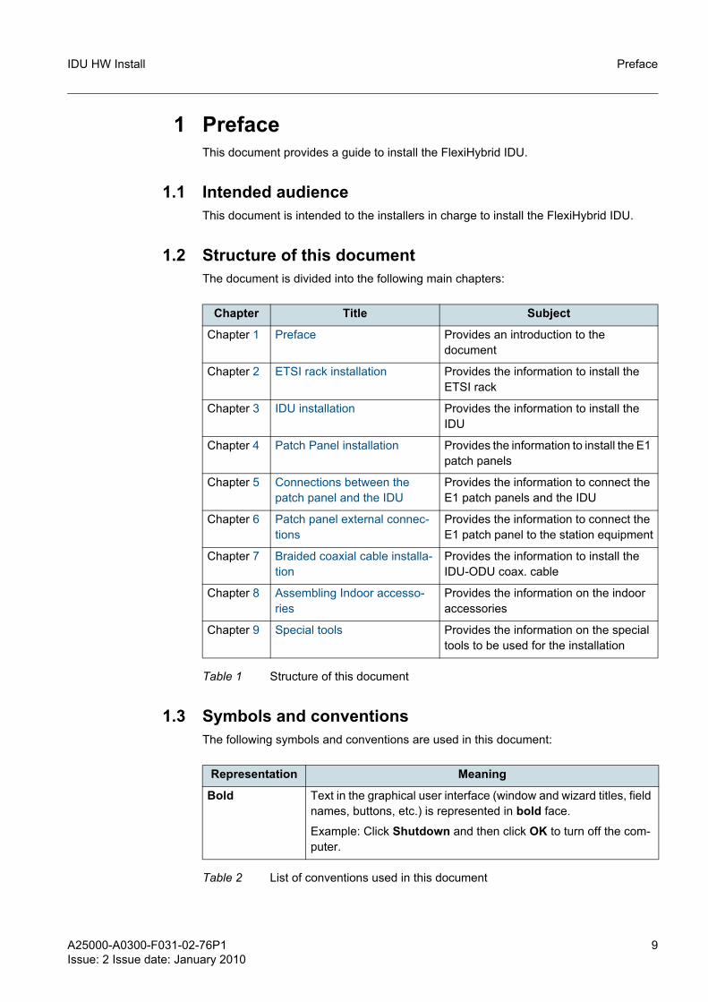
1.2 Structure of this documentThe document is divided into the following main chapters:
1.3 Symbols and conventionsThe following symbols and conventions are used in this document:
Chapter Title Subject
Chapter 1 Preface Provides an introduction to the document
Chapter 2 ETSI rack installation Provides the information to install the ETSI rack
Chapter 3 IDU installation Provides the information to install the IDU
Chapter 4 Patch Panel installation Provides the information to install the E1 patch panels
Chapter 5 Connections between the patch panel and the IDU
Provides the information to connect the E1 patch panels and the IDU
Chapter 6 Patch panel external connec-tions
Provides the information to connect the E1 patch panel to the station equipment
Chapter 7 Braided coaxial cable installa-tion
Provides the information to install the IDU-ODU coax. cable
Chapter 8 Assembling Indoor accesso-ries
Provides the information on the indoor accessories
Chapter 9 Special tools Provides the information on the special tools to be used for the installation
Table 1 Structure of this document
Representation Meaning
Bold Text in the graphical user interface (window and wizard titles, field names, buttons, etc.) is represented in bold face.
Example: Click Shutdown and then click OK to turn off the com-puter.
Table 2 List of conventions used in this document
10 A25000-A0300-F031-02-76P1Issue: 2 Issue date: January 2010
IDU HW InstallPreface
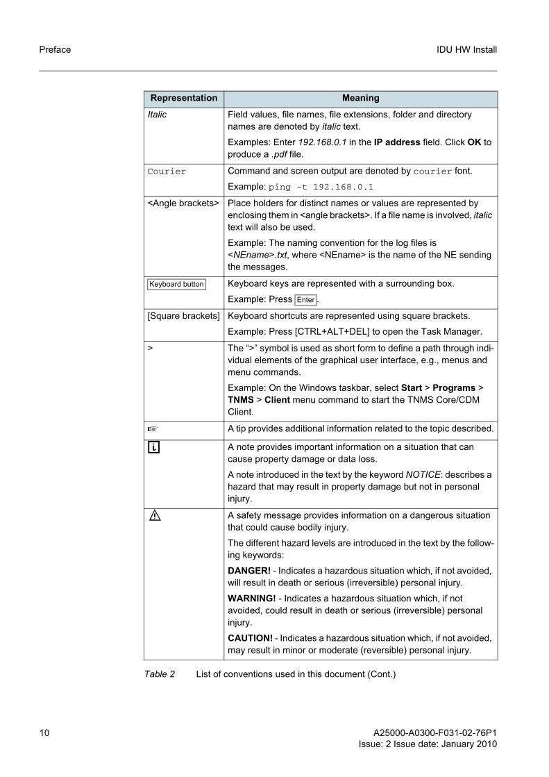
Italic Field values, file names, file extensions, folder and directory names are denoted by italic text.
Examples: Enter 192.168.0.1 in the IP address field. Click OK to produce a .pdf file.
Courier Command and screen output are denoted by courier font.
Example: ping -t 192.168.0.1
<Angle brackets> Place holders for distinct names or values are represented by enclosing them in <angle brackets>. If a file name is involved, italic text will also be used.
Example: The naming convention for the log files is <NEname>.txt, where <NEname> is the name of the NE sending the messages.
Keyboard button Keyboard keys are represented with a surrounding box.
Example: Press Enter .
[Square brackets] Keyboard shortcuts are represented using square brackets.
Example: Press [CTRL+ALT+DEL] to open the Task Manager.
> The “>” symbol is used as short form to define a path through indi-vidual elements of the graphical user interface, e.g., menus and menu commands.
Example: On the Windows taskbar, select Start > Programs > TNMS > Client menu command to start the TNMS Core/CDM Client.
☞ A tip provides additional information related to the topic described.
g A note provides important information on a situation that can cause property damage or data loss.
A note introduced in the text by the keyword NOTICE: describes a hazard that may result in property damage but not in personal injury.
f A safety message provides information on a dangerous situation that could cause bodily injury.
The different hazard levels are introduced in the text by the follow-ing keywords:
DANGER! - Indicates a hazardous situation which, if not avoided, will result in death or serious (irreversible) personal injury.
WARNING! - Indicates a hazardous situation which, if not avoided, could result in death or serious (irreversible) personal injury.
CAUTION! - Indicates a hazardous situation which, if not avoided, may result in minor or moderate (reversible) personal injury.
Representation Meaning
Table 2 List of conventions used in this document (Cont.)
A25000-A0300-F031-02-76P1Issue: 2 Issue date: January 2010
11
IDU HW Install Preface
Screenshots of the graphical user interface are examples only to illustrate principles. This especially applies to a software version number visible in a screenshot.
1.4 History of changes
1.5 Waste electrical and electronic equipment (WEEE)All waste electrical and electronic products must be disposed of separately from the municipal waste stream via designated collection facilities appointed by the government or the local authorities. The WEEE label (see Figure 1) is applied to all such devices.
Figure 1 WEEE label
The correct disposal and separate collection of waste equipment will help prevent poten-tial negative consequences for the environment and human health. It is a precondition for reuse and recycling of used electrical and electronic equipment.
For more detailed information about disposal of such equipment, please contact Nokia Siemens Networks.
The above statements are fully valid only for equipment installed in the countries of the European Union and is covered by the directive 2002/96/EC. Countries outside the European Union may have other regulations regarding the disposal of electrical and electronic equipment.
1.6 RoHS complianceFlexiPacket Radio complies with the European Union RoHS Directive 2002/95/EC on the restriction of use of certain hazardous substances in electrical and electronic equip-ment.
The directive applies to the use of lead, mercury, cadmium, hexavalent chromium, poly-brominated biphenyls (PBB), and polybrominated diphenylethers (PBDE) in electrical and electronic equipment put on the market after 1 July 2006.
Materials usage information on Nokia Siemens Networks Electronic Information Products imported or sold in the People’s Republic of China
Issue Issue date Remarks
1 October 2009 1st version
2 January 2010 Par. 7.3 has been removed
Table 3 History of changes

12 A25000-A0300-F031-02-76P1Issue: 2 Issue date: January 2010
IDU HW InstallPreface
FlexiPacket Radio complies with the Chinese standard SJ/T 11364-2006 on the restric-tion of the use of certain hazardous substances in electrical and electronic equipment. The standard applies to the use of lead, mercury, cadmium, hexavalent chromium, poly-brominated biphenyls (PBB), and polybrominated diphenyl ethers (PBDE) in electrical and electronic equipment put on the market after 1 March 2007.
A25000-A0300-F031-02-76P1Issue: 2 Issue date: January 2010
13
IDU HW Install ETSI rack installation
2 ETSI rack installation
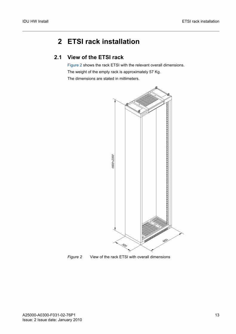
2.1 View of the ETSI rackFigure 2 shows the rack ETSI with the relevant overall dimensions.
The weight of the empty rack is approximately 57 Kg.
The dimensions are stated in millimeters.
Figure 2 View of the rack ETSI with overall dimensions
14 A25000-A0300-F031-02-76P1Issue: 2 Issue date: January 2010
IDU HW InstallETSI rack installation
2.2 Drilling planes
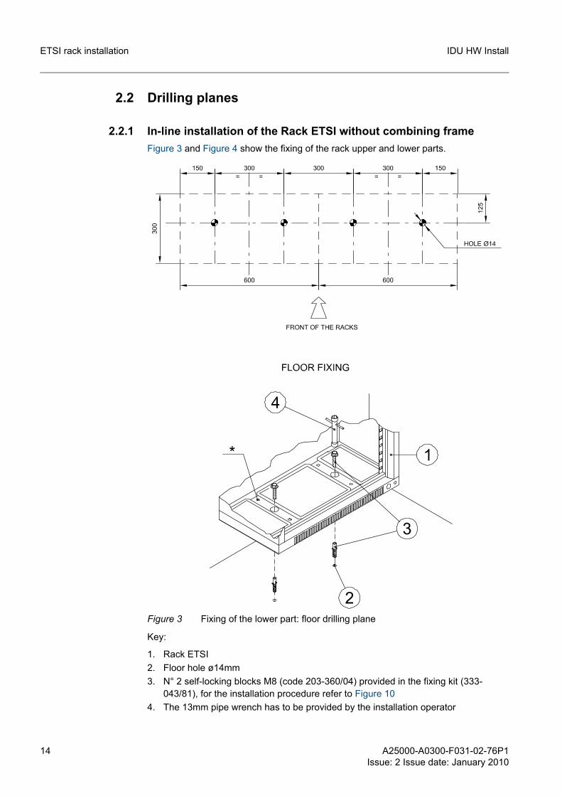
2.2.1 In-line installation of the Rack ETSI without combining frameFigure 3 and Figure 4 show the fixing of the rack upper and lower parts.
Figure 3 Fixing of the lower part: floor drilling plane
Key:
1. Rack ETSI2. Floor hole ø14mm3. N° 2 self-locking blocks M8 (code 203-360/04) provided in the fixing kit (333-
043/81), for the installation procedure refer to Figure 104. The 13mm pipe wrench has to be provided by the installation operator
A25000-A0300-F031-02-76P1Issue: 2 Issue date: January 2010
15
IDU HW Install ETSI rack installation
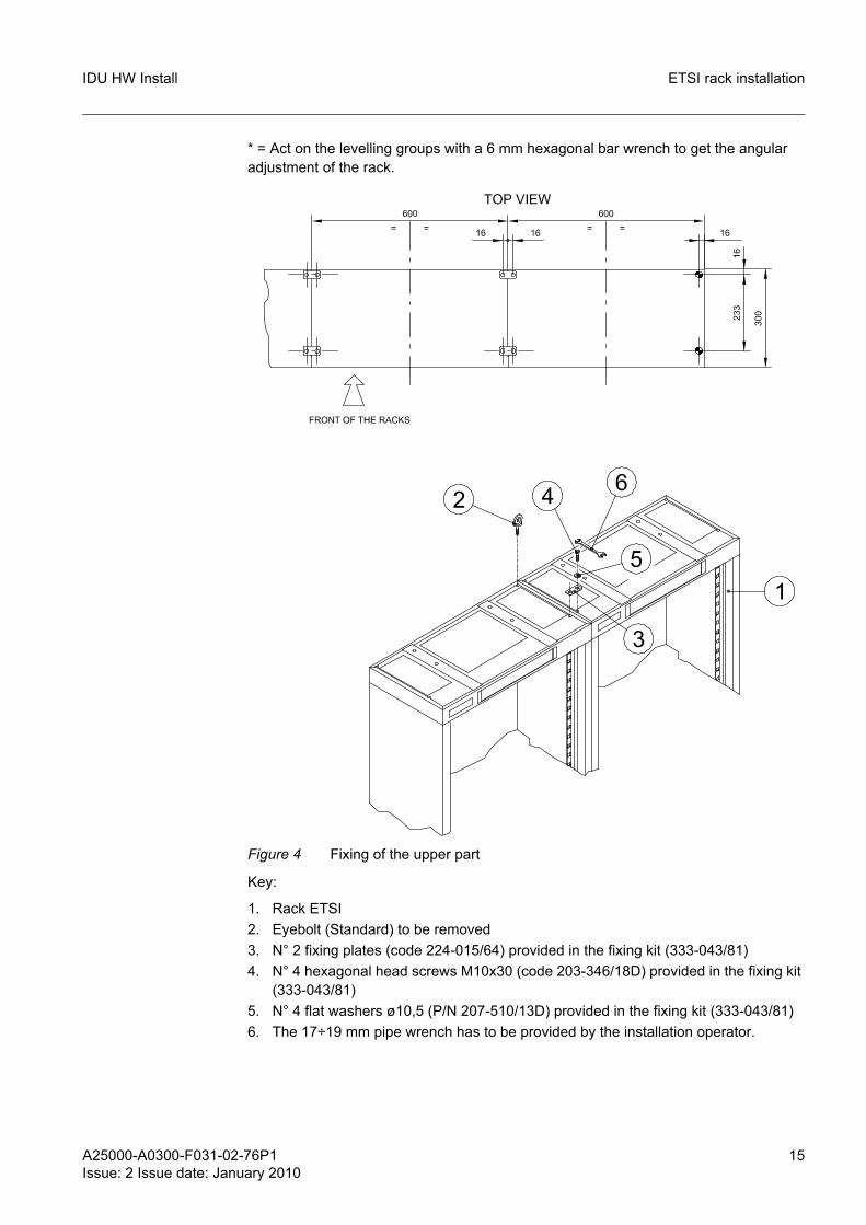
* = Act on the levelling groups with a 6 mm hexagonal bar wrench to get the angular adjustment of the rack.
Figure 4 Fixing of the upper part
Key:
1. Rack ETSI2. Eyebolt (Standard) to be removed3. N° 2 fixing plates (code 224-015/64) provided in the fixing kit (333-043/81)4. N° 4 hexagonal head screws M10x30 (code 203-346/18D) provided in the fixing kit
(333-043/81)5. N° 4 flat washers ø10,5 (P/N 207-510/13D) provided in the fixing kit (333-043/81)6. The 17÷19 mm pipe wrench has to be provided by the installation operator.
16 A25000-A0300-F031-02-76P1Issue: 2 Issue date: January 2010
IDU HW InstallETSI rack installation
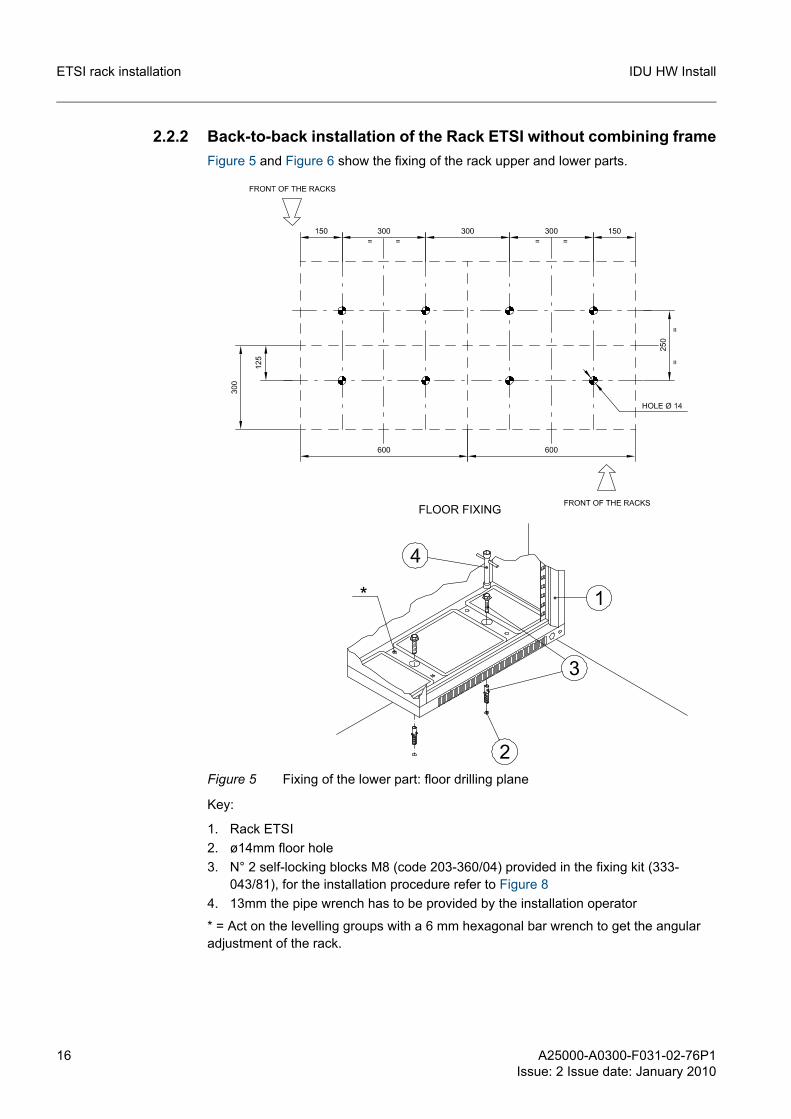
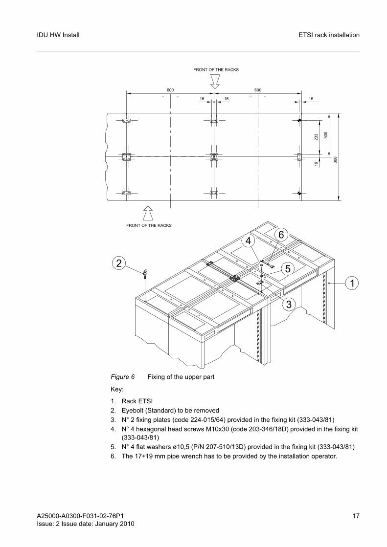
2.2.2 Back-to-back installation of the Rack ETSI without combining frameFigure 5 and Figure 6 show the fixing of the rack upper and lower parts.
Figure 5 Fixing of the lower part: floor drilling plane
Key:
1. Rack ETSI2. ø14mm floor hole 3. N° 2 self-locking blocks M8 (code 203-360/04) provided in the fixing kit (333-
043/81), for the installation procedure refer to Figure 84. 13mm the pipe wrench has to be provided by the installation operator
* = Act on the levelling groups with a 6 mm hexagonal bar wrench to get the angular adjustment of the rack.
A25000-A0300-F031-02-76P1Issue: 2 Issue date: January 2010
17
IDU HW Install ETSI rack installation
Figure 6 Fixing of the upper part
Key:
1. Rack ETSI2. Eyebolt (Standard) to be removed3. N° 2 fixing plates (code 224-015/64) provided in the fixing kit (333-043/81)4. N° 4 hexagonal head screws M10x30 (code 203-346/18D) provided in the fixing kit
(333-043/81)5. N° 4 flat washers ø10,5 (P/N 207-510/13D) provided in the fixing kit (333-043/81)6. The 17÷19 mm pipe wrench has to be provided by the installation operator.
18 A25000-A0300-F031-02-76P1Issue: 2 Issue date: January 2010
IDU HW InstallETSI rack installation
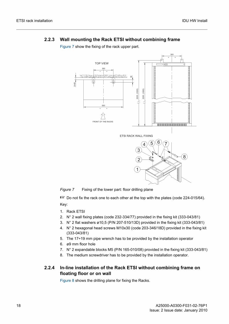
2.2.3 Wall mounting the Rack ETSI without combining frameFigure 7 show the fixing of the rack upper part.
Figure 7 Fixing of the lower part: floor drilling plane
☞ Do not fix the rack one to each other at the top with the plates (code 224-015/64).
Key:
1. Rack ETSI2. N° 2 wall fixing plates (code 232-334/77) provided in the fixing kit (333-043/81)3. N° 2 flat washers ø10,5 (P/N 207-510/13D) provided in the fixing kit (333-043/81)4. N° 2 hexagonal head screws M10x30 (code 203-346/18D) provided in the fixing kit
(333-043/81)5. The 17÷19 mm pipe wrench has to be provided by the installation operator6. ø9 mm floor hole 7. N° 2 expandable blocks M5 (P/N 165-010/08) provided in the fixing kit (333-043/81)8. The medium screwdriver has to be provided by the installation operator.
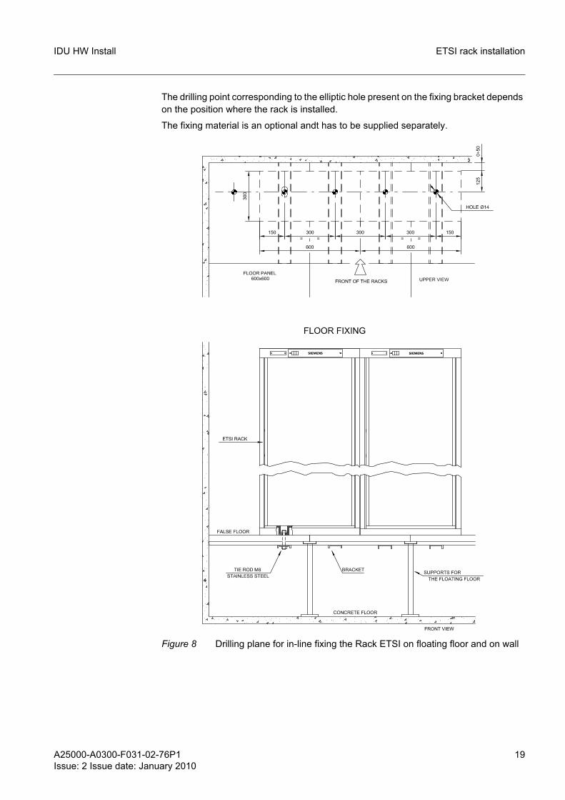
2.2.4 In-line installation of the Rack ETSI without combining frame on floating floor or on wallFigure 8 shows the drilling plane for fixing the Racks.
A25000-A0300-F031-02-76P1Issue: 2 Issue date: January 2010
19
IDU HW Install ETSI rack installation
The drilling point corresponding to the elliptic hole present on the fixing bracket depends on the position where the rack is installed.
The fixing material is an optional andt has to be supplied separately.
Figure 8 Drilling plane for in-line fixing the Rack ETSI on floating floor and on wall
20 A25000-A0300-F031-02-76P1Issue: 2 Issue date: January 2010
IDU HW InstallETSI rack installation
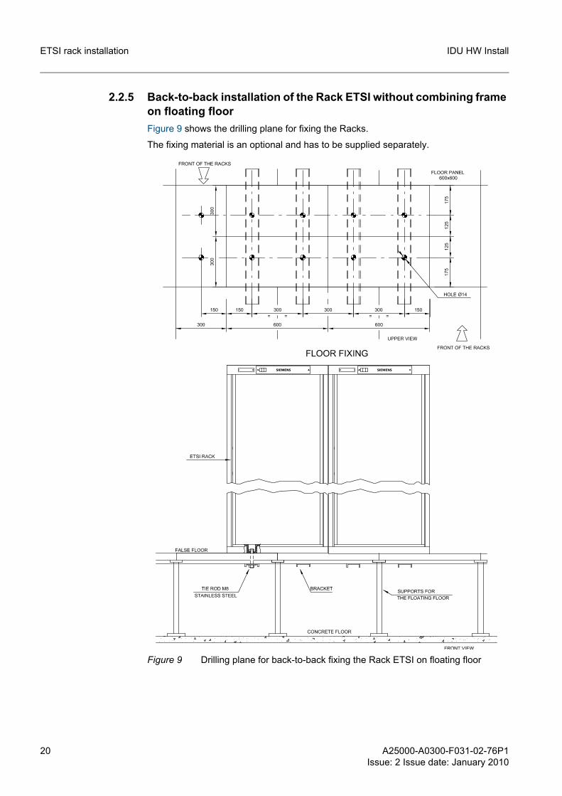
2.2.5 Back-to-back installation of the Rack ETSI without combining frame on floating floorFigure 9 shows the drilling plane for fixing the Racks.
The fixing material is an optional and has to be supplied separately.
Figure 9 Drilling plane for back-to-back fixing the Rack ETSI on floating floor
A25000-A0300-F031-02-76P1Issue: 2 Issue date: January 2010
21
IDU HW Install ETSI rack installation
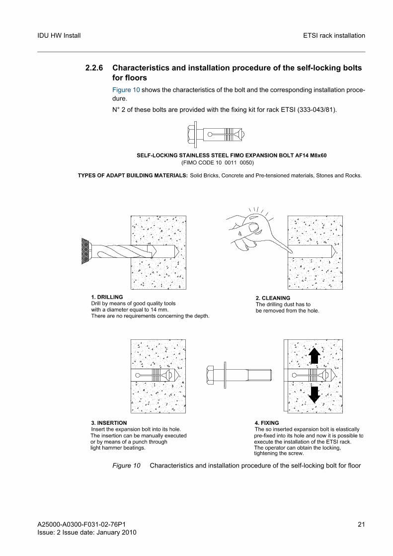
2.2.6 Characteristics and installation procedure of the self-locking bolts for floorsFigure 10 shows the characteristics of the bolt and the corresponding installation proce-dure.
N° 2 of these bolts are provided with the fixing kit for rack ETSI (333-043/81).
Figure 10 Characteristics and installation procedure of the self-locking bolt for floor
22 A25000-A0300-F031-02-76P1Issue: 2 Issue date: January 2010
IDU HW InstallETSI rack installation
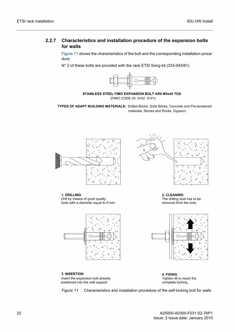
2.2.7 Characteristics and installation procedure of the expansion bolts for wallsFigure 11 shows the characteristics of the bolt and the corresponding installation proce-dure.
N° 2 of these bolts are provided with the rack ETSI fixing kit (333-043/81).
Figure 11 Characteristics and installation procedure of the self-locking bolt for walls
A25000-A0300-F031-02-76P1Issue: 2 Issue date: January 2010
23
IDU HW Install ETSI rack installation
2.3 Connections
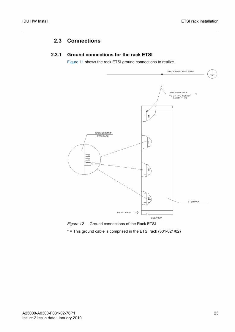
2.3.1 Ground connections for the rack ETSIFigure 11 shows the rack ETSI ground connections to realize.
Figure 12 Ground connections of the Rack ETSI
* = This ground cable is comprised in the ETSI rack (301-021/02)
24 A25000-A0300-F031-02-76P1Issue: 2 Issue date: January 2010
IDU HW InstallIDU installation
3 IDU installation
3.1 IDU installation in the ETSI rackInsert the cage nuts into the square slots of the rack, on the required positions.
Fix the sub-rack by means of four M6x16 screws.
Connect the coaxial cables as stated in section 3.2 External connections.
The ODU connection cables are placed along the side wall of the rack.
☞ The IDU can also be installed in the FOC (Flexi Outdoor Case).
Refer to the FOC relevant documentation.
3.2 External connectionsAll the connectors used for the external connections of the IDU units are easily accessi-ble from the front panel of the indoor assembly.
All the cables from/to the outside source are brought down from the cabinet top inside the side wall slots or, should the wiring be running under the raised floor, they are made to run up in the like manner.
☞ The E1 tributary connections can be carried out to the FlexiHybrid patch panels or directly to the station equipment.
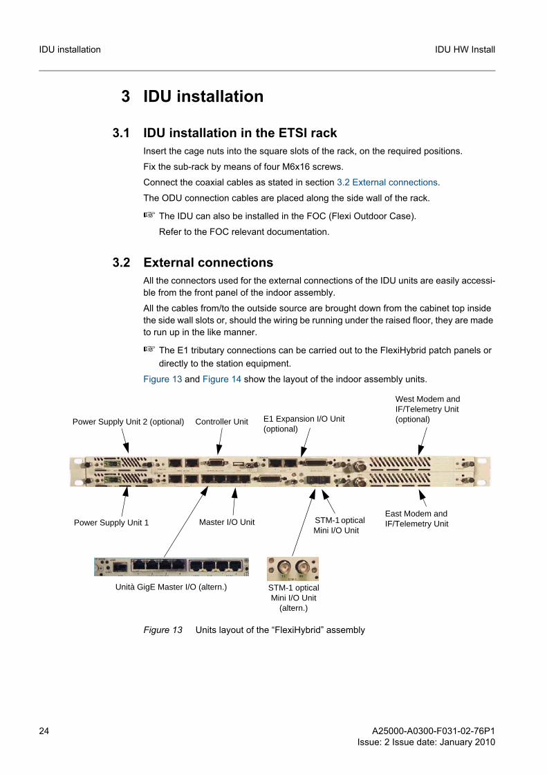
Figure 13 and Figure 14 show the layout of the indoor assembly units.
Figure 13 Units layout of the “FlexiHybrid” assembly
Power Supply Unit 1
Power Supply Unit 2 (optional) Controller Unit E1 Expansion I/O Unit (optional)
West Modem and IF/Telemetry Unit (optional)
East Modem and IF/Telemetry Unit Master I/O Unit STM-1 optical
Mini I/O Unit
STM-1 optical Mini I/O Unit
(altern.)
Unità GigE Master I/O (altern.)
A25000-A0300-F031-02-76P1Issue: 2 Issue date: January 2010
25
IDU HW Install IDU installation
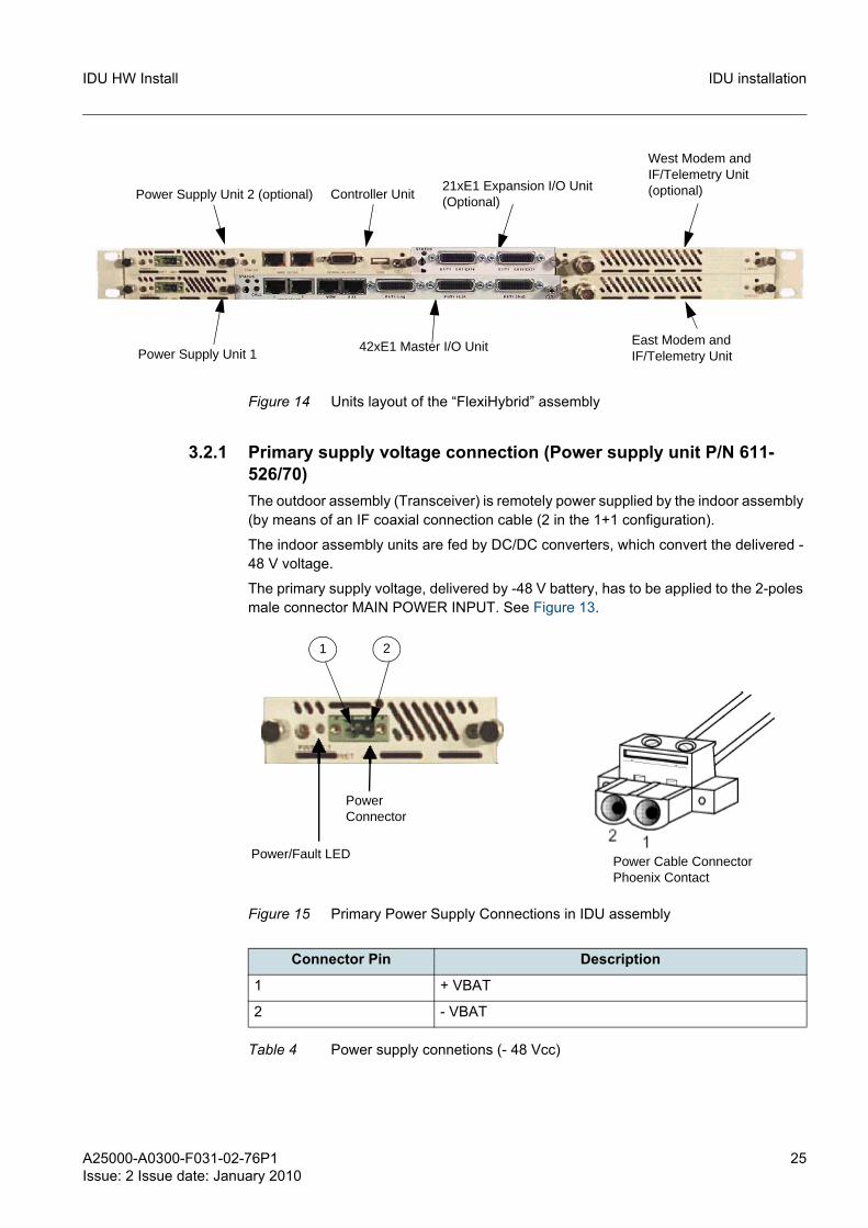
Figure 14 Units layout of the “FlexiHybrid” assembly
3.2.1 Primary supply voltage connection (Power supply unit P/N 611-526/70)The outdoor assembly (Transceiver) is remotely power supplied by the indoor assembly (by means of an IF coaxial connection cable (2 in the 1+1 configuration).
The indoor assembly units are fed by DC/DC converters, which convert the delivered -48 V voltage.
The primary supply voltage, delivered by -48 V battery, has to be applied to the 2-poles male connector MAIN POWER INPUT. See Figure 13.
Figure 15 Primary Power Supply Connections in IDU assembly
Power Supply Unit 1
Power Supply Unit 2 (optional) Controller Unit
West Modem and IF/Telemetry Unit (optional)
East Modem and IF/Telemetry Unit
21xE1 Expansion I/O Unit(Optional)
42xE1 Master I/O Unit
Connector Pin Description
1 + VBAT
2 - VBAT
Table 4 Power supply connetions (- 48 Vcc)
Power/Fault LED
Power Connector
Power Cable Connector Phoenix Contact
1 2
26 A25000-A0300-F031-02-76P1Issue: 2 Issue date: January 2010
IDU HW InstallIDU installation
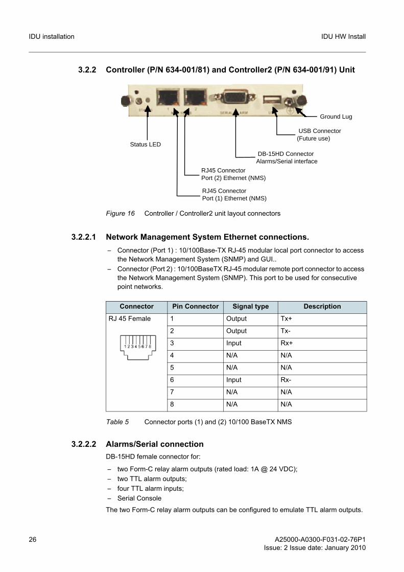
3.2.2 Controller (P/N 634-001/81) and Controller2 (P/N 634-001/91) Unit
Figure 16 Controller / Controller2 unit layout connectors
3.2.2.1 Network Management System Ethernet connections.– Connector (Port 1) : 10/100Base-TX RJ-45 modular local port connector to access
the Network Management System (SNMP) and GUI..– Connector (Port 2) : 10/100BaseTX RJ-45 modular remote port connector to access
the Network Management System (SNMP). This port to be used for consecutive point networks.
3.2.2.2 Alarms/Serial connectionDB-15HD female connector for:
– two Form-C relay alarm outputs (rated load: 1A @ 24 VDC);– two TTL alarm outputs;– four TTL alarm inputs;– Serial Console
The two Form-C relay alarm outputs can be configured to emulate TTL alarm outputs.
Status LED
RJ45 ConnectorPort (2) Ethernet (NMS)
DB-15HD ConnectorAlarms/Serial interface
RJ45 Connector Port (1) Ethernet (NMS)
USB Connector(Future use)
Ground Lug
Connector Pin Connector Signal type Description
RJ 45 Female 1 Output Tx+
2 Output Tx-
3 Input Rx+
4 N/A N/A
5 N/A N/A
6 Input Rx-
7 N/A N/A
8 N/A N/A
Table 5 Connector ports (1) and (2) 10/100 BaseTX NMS
A25000-A0300-F031-02-76P1Issue: 2 Issue date: January 2010
27
IDU HW Install IDU installation
Note 1: Pins 2 and 3 are hardware jumper configurable for DCE or DTE operation.
Note 2: C Contacts are hardware jumper configurable to emulate TTL outputs.
Note 3: Outputs Alarm 3 and 4 are TTL type:
– When output Alarm 4 is disabled, between pin 4 and pin 5 the voltage is 0.7 Volt; when enabled, the voltage is 5 Volt.
– When output Alarm 3 is disabled, between pin 1 and pin 5 the voltage is 0.7 Volt; when enabled, the voltage is 5 Volt.
Note 4: Outputs Alarm 1 and 2 are Relay type:
– When output Alarm 2 is disabled, pin 8 is connected to pin 12; when enabled, pin 8 is connected to pin 13.
– When output Alarm 1 is disabled, pin 11 is connected to pin 6; when enabled, pin 11 is connected to pin 7.
3.2.2.3 USB Connection (future use)Not supported in the current SVR.
Connector Pin Connector Signal type Description
DB-15HD Female 1 Output TTL Alarm Output 3
2 Input/Output RS232 Rx/Tx
3 Output/Input RS232 Tx/Rx
4 Output TTL Alarm Output 4
5 N/A GROUND
6 N/A Alarm 1 Form C Contact Normally Open
7 N/A Alarm 1 Form C Contact Normally Closed
8 N/A Alarm 2 Form C Contact Common
9 Input TTL Alarm Input 1
10 Input TTL Alarm Input 3
11 N/A Alarm 1 Form C Contact Common
12 N/A Alarm 2 Form C Contact Normally Open
13 N/A Alarm 2 Form C Contact Normally Closed
14 Input TTL Alarm Input 2
15 Input TTL Alarm Input 4
Table 6 Alarms/Serial connector
28 A25000-A0300-F031-02-76P1Issue: 2 Issue date: January 2010
IDU HW InstallIDU installation
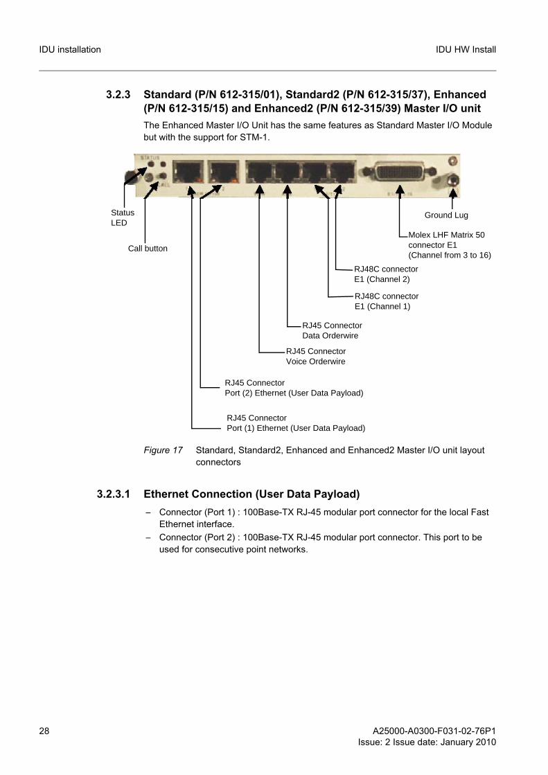
3.2.3 Standard (P/N 612-315/01), Standard2 (P/N 612-315/37), Enhanced (P/N 612-315/15) and Enhanced2 (P/N 612-315/39) Master I/O unitThe Enhanced Master I/O Unit has the same features as Standard Master I/O Module but with the support for STM-1.
Figure 17 Standard, Standard2, Enhanced and Enhanced2 Master I/O unit layout connectors
3.2.3.1 Ethernet Connection (User Data Payload)– Connector (Port 1) : 100Base-TX RJ-45 modular port connector for the local Fast
Ethernet interface.– Connector (Port 2) : 100Base-TX RJ-45 modular port connector. This port to be
used for consecutive point networks.
Status LED
RJ45 ConnectorPort (2) Ethernet (User Data Payload)
Molex LHF Matrix 50connector E1(Channel from 3 to 16)
Ground Lug
Call button
RJ45 ConnectorPort (1) Ethernet (User Data Payload)
RJ45 Connector Voice Orderwire
RJ45 Connector Data Orderwire
RJ48C connectorE1 (Channel 1)
RJ48C connectorE1 (Channel 2)
A25000-A0300-F031-02-76P1Issue: 2 Issue date: January 2010
29
IDU HW Install IDU installation
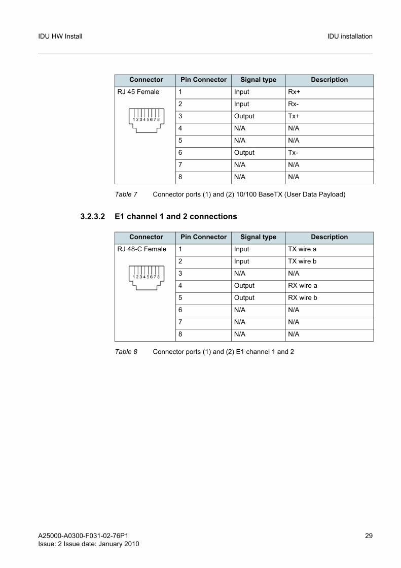
3.2.3.2 E1 channel 1 and 2 connections
Connector Pin Connector Signal type Description
RJ 45 Female 1 Input Rx+
2 Input Rx-
3 Output Tx+
4 N/A N/A
5 N/A N/A
6 Output Tx-
7 N/A N/A
8 N/A N/A
Table 7 Connector ports (1) and (2) 10/100 BaseTX (User Data Payload)
Connector Pin Connector Signal type Description
RJ 48-C Female 1 Input TX wire a
2 Input TX wire b
3 N/A N/A
4 Output RX wire a
5 Output RX wire b
6 N/A N/A
7 N/A N/A
8 N/A N/A
Table 8 Connector ports (1) and (2) E1 channel 1 and 2
30 A25000-A0300-F031-02-76P1Issue: 2 Issue date: January 2010
IDU HW InstallIDU installation
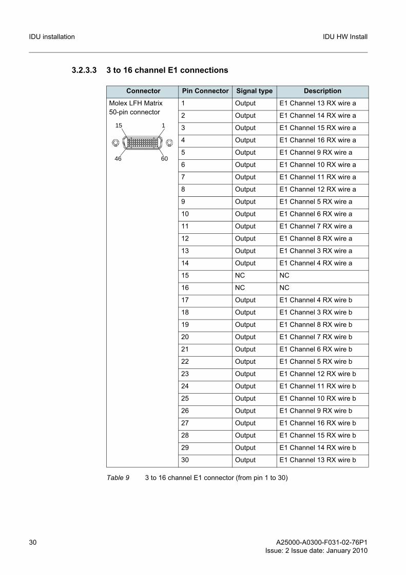
3.2.3.3 3 to 16 channel E1 connections
Connector Pin Connector Signal type Description
Molex LFH Matrix 50-pin connector
1 Output E1 Channel 13 RX wire a
2 Output E1 Channel 14 RX wire a
3 Output E1 Channel 15 RX wire a
4 Output E1 Channel 16 RX wire a
5 Output E1 Channel 9 RX wire a
6 Output E1 Channel 10 RX wire a
7 Output E1 Channel 11 RX wire a
8 Output E1 Channel 12 RX wire a
9 Output E1 Channel 5 RX wire a
10 Output E1 Channel 6 RX wire a
11 Output E1 Channel 7 RX wire a
12 Output E1 Channel 8 RX wire a
13 Output E1 Channel 3 RX wire a
14 Output E1 Channel 4 RX wire a
15 NC NC
16 NC NC
17 Output E1 Channel 4 RX wire b
18 Output E1 Channel 3 RX wire b
19 Output E1 Channel 8 RX wire b
20 Output E1 Channel 7 RX wire b
21 Output E1 Channel 6 RX wire b
22 Output E1 Channel 5 RX wire b
23 Output E1 Channel 12 RX wire b
24 Output E1 Channel 11 RX wire b
25 Output E1 Channel 10 RX wire b
26 Output E1 Channel 9 RX wire b
27 Output E1 Channel 16 RX wire b
28 Output E1 Channel 15 RX wire b
29 Output E1 Channel 14 RX wire b
30 Output E1 Channel 13 RX wire b
Table 9 3 to 16 channel E1 connector (from pin 1 to 30)
1
60
15
46

A25000-A0300-F031-02-76P1Issue: 2 Issue date: January 2010
31
IDU HW Install IDU installation
Connector Pin Connector Signal type Description
Molex LFH Matrix 50-pin connector
31 Input E1 Channel 16 TX wire a
32 Input E1 Channel 15 TX wire a
33 Input E1 Channel 9 TX wire a
34 Input E1 Channel 14 TX wire a
35 Input E1 Channel 10 TX wire a
36 Input E1 Channel 13 TX wire a
37 Input E1 Channel 11 TX wire a
38 Input E1 Channel 4 TX wire a
39 Input E1 Channel 12 TX wire a
40 Input E1 Channel 3 TX wire a
41 Input E1 Channel 5 TX wire a
42 Input E1 Channel 8 TX wire a
43 Input E1 Channel 6 TX wire a
44 Input E1 Channel 7 TX wire a
45 NC NC
46 NC NC
47 Input E1 Channel 7 TX wire b
48 Input E1 Channel 6 TX wire b
49 Input E1 Channel 8 TX wire b
50 Input E1 Channel 5 TX wire b
51 Input E1 Channel 3 TX wire b
52 Input E1 Channel 12 TX wire b
53 Input E1 Channel 4 TX wire b
54 Input E1 Channel 11 TX wire b
55 Input E1 Channel 13 TX wire b
56 Input E1 Channel 10 TX wire b
57 Input E1 Channel 14 TX wire b
58 Input E1 Channel 9 TX wire b
59 Input E1 Channel 15 TX wire b
60 Input E1 Channel 16 TX wire b
Table 10 3 to 16 channel E1 connector (from pin 31 to 60)
1
60
15
46

32 A25000-A0300-F031-02-76P1Issue: 2 Issue date: January 2010
IDU HW InstallIDU installation
Figure 18 HD-60 14xE1 shielded cable
A25000-A0300-F031-02-76P1Issue: 2 Issue date: January 2010
33
IDU HW Install IDU installation
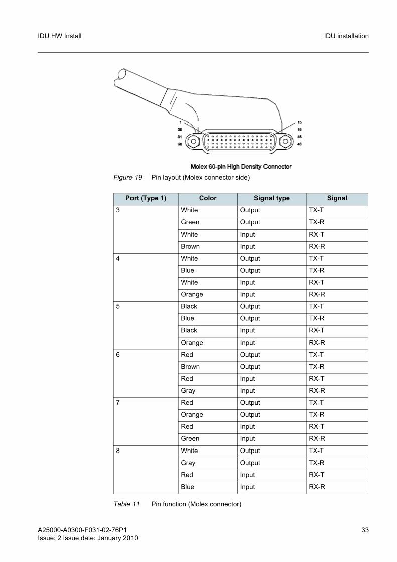
Figure 19 Pin layout (Molex connector side)
Port (Type 1) Color Signal type Signal
3 White Output TX-T
Green Output TX-R
White Input RX-T
Brown Input RX-R
4 White Output TX-T
Blue Output TX-R
White Input RX-T
Orange Input RX-R
5 Black Output TX-T
Blue Output TX-R
Black Input RX-T
Orange Input RX-R
6 Red Output TX-T
Brown Output TX-R
Red Input RX-T
Gray Input RX-R
7 Red Output TX-T
Orange Output TX-R
Red Input RX-T
Green Input RX-R
8 White Output TX-T
Gray Output TX-R
Red Input RX-T
Blue Input RX-R
Table 11 Pin function (Molex connector)
34 A25000-A0300-F031-02-76P1Issue: 2 Issue date: January 2010
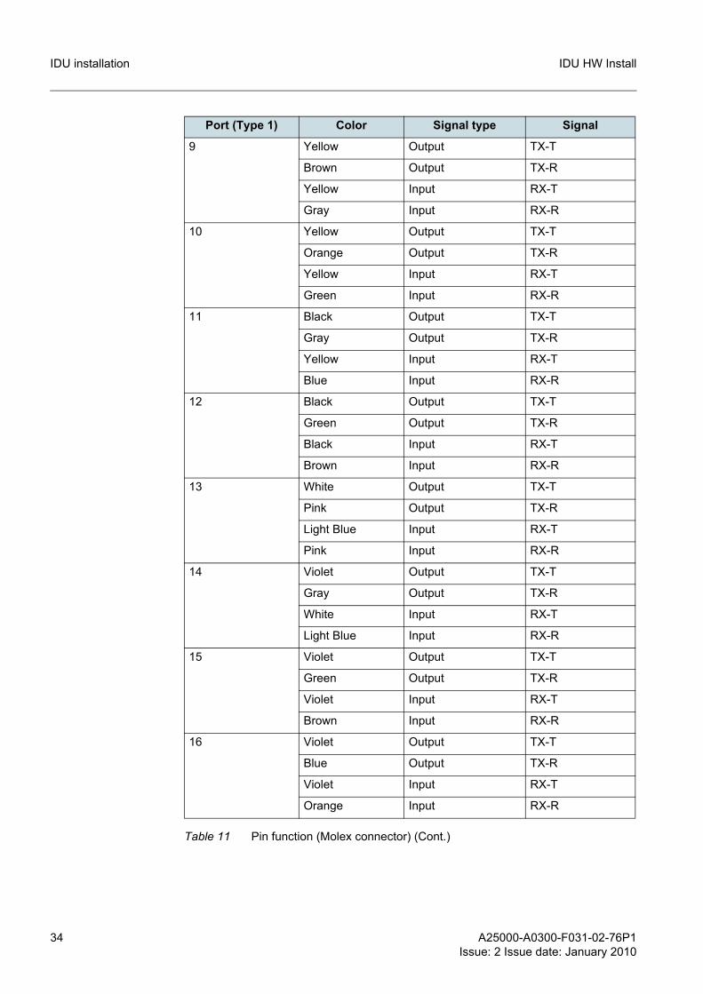
IDU HW InstallIDU installation
9 Yellow Output TX-T
Brown Output TX-R
Yellow Input RX-T
Gray Input RX-R
10 Yellow Output TX-T
Orange Output TX-R
Yellow Input RX-T
Green Input RX-R
11 Black Output TX-T
Gray Output TX-R
Yellow Input RX-T
Blue Input RX-R
12 Black Output TX-T
Green Output TX-R
Black Input RX-T
Brown Input RX-R
13 White Output TX-T
Pink Output TX-R
Light Blue Input RX-T
Pink Input RX-R
14 Violet Output TX-T
Gray Output TX-R
White Input RX-T
Light Blue Input RX-R
15 Violet Output TX-T
Green Output TX-R
Violet Input RX-T
Brown Input RX-R
16 Violet Output TX-T
Blue Output TX-R
Violet Input RX-T
Orange Input RX-R
Port (Type 1) Color Signal type Signal
Table 11 Pin function (Molex connector) (Cont.)
A25000-A0300-F031-02-76P1Issue: 2 Issue date: January 2010
35
IDU HW Install IDU installation
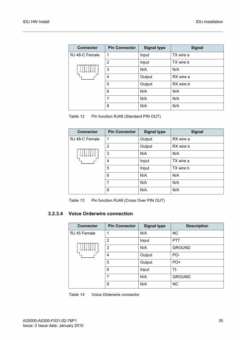
3.2.3.4 Voice Orderwire connection
Connector Pin Connector Signal type Signal
RJ 48-C Female 1 Input TX wire a
2 Input TX wire b
3 N/A N/A
4 Output RX wire a
5 Output RX wire b
6 N/A N/A
7 N/A N/A
8 N/A N/A
Table 12 Pin function RJ48 (Standard PIN OUT)
Connector Pin Connector Signal type Signal
RJ 48-C Female 1 Output RX wire a
2 Output RX wire b
3 N/A N/A
4 Input TX wire a
5 Input TX wire b
6 N/A N/A
7 N/A N/A
8 N/A N/A
Table 13 Pin function RJ48 (Cross Over PIN OUT)
Connector Pin Connector Signal type Description
RJ 45 Female 1 N/A NC
2 Input PTT
3 N/A GROUND
4 Output PO-
5 Output PO+
6 Input TI-
7 N/A GROUND
8 N/A NC
Table 14 Voice Orderwire connector

36 A25000-A0300-F031-02-76P1Issue: 2 Issue date: January 2010
IDU HW InstallIDU installation
3.2.3.5 DATA Orderwire connection The data orderwire channel can have two different interfaces: RS232 or RS422 (soft-ware selectable).
Connector Pin Connector Signal type Description
RJ 45 Female 1 Output TX Clock -
2 Output TX Clock +
3 Output TX Data -
4 Input RX Data -
5 Input RX Data +
6 Output TX Data +
7 Input RX Clock -
8 Input RX Clock +
Table 15 DATA Orderwire (RS422) connection
Connector Pin Connector Signal type Description
RJ 45 Female 1 N/A NC
2 N/A NC
3 N/A GROUND
4 N/A NC
5 Input RX Data +
6 Output TX Data +
7 N/A NC
8 N/A NC
Table 16 DATA Orderwire (RS232) connection
A25000-A0300-F031-02-76P1Issue: 2 Issue date: January 2010
37
IDU HW Install IDU installation
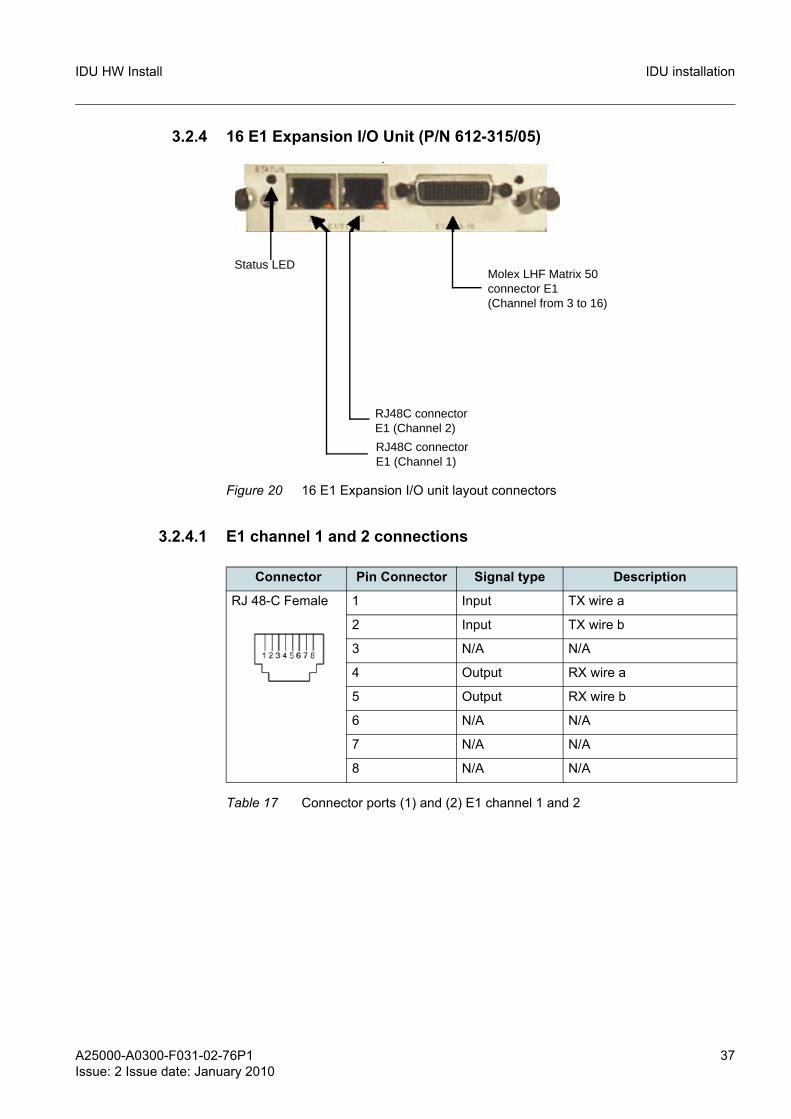
3.2.4 16 E1 Expansion I/O Unit (P/N 612-315/05)
Figure 20 16 E1 Expansion I/O unit layout connectors
3.2.4.1 E1 channel 1 and 2 connections
Status LEDMolex LHF Matrix 50connector E1(Channel from 3 to 16)
RJ48C connectorE1 (Channel 1)
RJ48C connectorE1 (Channel 2)
Connector Pin Connector Signal type Description
RJ 48-C Female 1 Input TX wire a
2 Input TX wire b
3 N/A N/A
4 Output RX wire a
5 Output RX wire b
6 N/A N/A
7 N/A N/A
8 N/A N/A
Table 17 Connector ports (1) and (2) E1 channel 1 and 2
38 A25000-A0300-F031-02-76P1Issue: 2 Issue date: January 2010
IDU HW InstallIDU installation
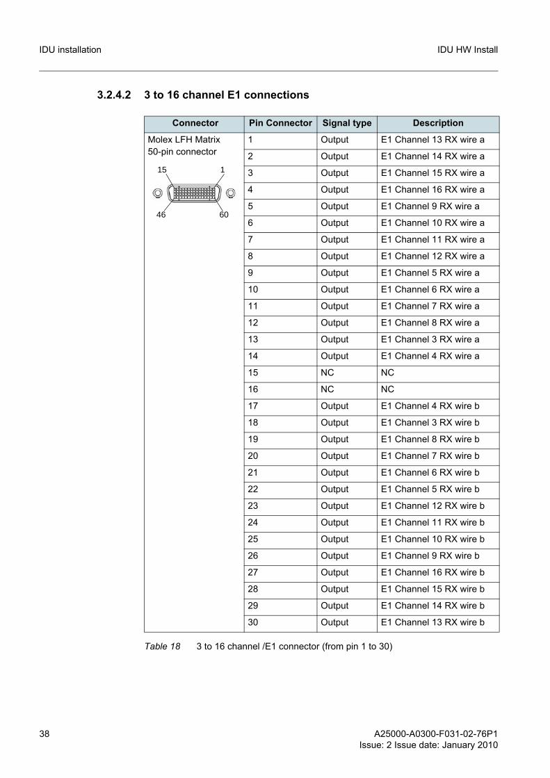
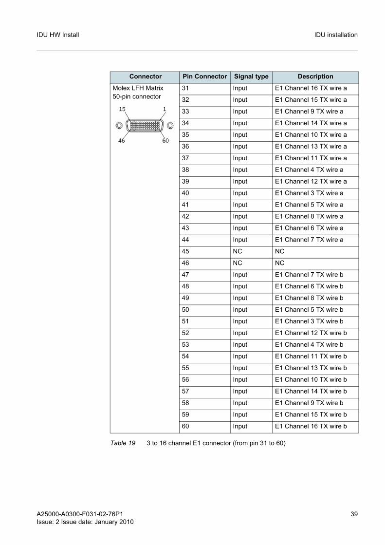
3.2.4.2 3 to 16 channel E1 connections
Connector Pin Connector Signal type Description
Molex LFH Matrix 50-pin connector
1 Output E1 Channel 13 RX wire a
2 Output E1 Channel 14 RX wire a
3 Output E1 Channel 15 RX wire a
4 Output E1 Channel 16 RX wire a
5 Output E1 Channel 9 RX wire a
6 Output E1 Channel 10 RX wire a
7 Output E1 Channel 11 RX wire a
8 Output E1 Channel 12 RX wire a
9 Output E1 Channel 5 RX wire a
10 Output E1 Channel 6 RX wire a
11 Output E1 Channel 7 RX wire a
12 Output E1 Channel 8 RX wire a
13 Output E1 Channel 3 RX wire a
14 Output E1 Channel 4 RX wire a
15 NC NC
16 NC NC
17 Output E1 Channel 4 RX wire b
18 Output E1 Channel 3 RX wire b
19 Output E1 Channel 8 RX wire b
20 Output E1 Channel 7 RX wire b
21 Output E1 Channel 6 RX wire b
22 Output E1 Channel 5 RX wire b
23 Output E1 Channel 12 RX wire b
24 Output E1 Channel 11 RX wire b
25 Output E1 Channel 10 RX wire b
26 Output E1 Channel 9 RX wire b
27 Output E1 Channel 16 RX wire b
28 Output E1 Channel 15 RX wire b
29 Output E1 Channel 14 RX wire b
30 Output E1 Channel 13 RX wire b
Table 18 3 to 16 channel /E1 connector (from pin 1 to 30)
1
60
15
46
A25000-A0300-F031-02-76P1Issue: 2 Issue date: January 2010
39
IDU HW Install IDU installation
Connector Pin Connector Signal type Description
Molex LFH Matrix 50-pin connector
31 Input E1 Channel 16 TX wire a
32 Input E1 Channel 15 TX wire a
33 Input E1 Channel 9 TX wire a
34 Input E1 Channel 14 TX wire a
35 Input E1 Channel 10 TX wire a
36 Input E1 Channel 13 TX wire a
37 Input E1 Channel 11 TX wire a
38 Input E1 Channel 4 TX wire a
39 Input E1 Channel 12 TX wire a
40 Input E1 Channel 3 TX wire a
41 Input E1 Channel 5 TX wire a
42 Input E1 Channel 8 TX wire a
43 Input E1 Channel 6 TX wire a
44 Input E1 Channel 7 TX wire a
45 NC NC
46 NC NC
47 Input E1 Channel 7 TX wire b
48 Input E1 Channel 6 TX wire b
49 Input E1 Channel 8 TX wire b
50 Input E1 Channel 5 TX wire b
51 Input E1 Channel 3 TX wire b
52 Input E1 Channel 12 TX wire b
53 Input E1 Channel 4 TX wire b
54 Input E1 Channel 11 TX wire b
55 Input E1 Channel 13 TX wire b
56 Input E1 Channel 10 TX wire b
57 Input E1 Channel 14 TX wire b
58 Input E1 Channel 9 TX wire b
59 Input E1 Channel 15 TX wire b
60 Input E1 Channel 16 TX wire b
Table 19 3 to 16 channel E1 connector (from pin 31 to 60)
1
60
15
46
40 A25000-A0300-F031-02-76P1Issue: 2 Issue date: January 2010
IDU HW InstallIDU installation
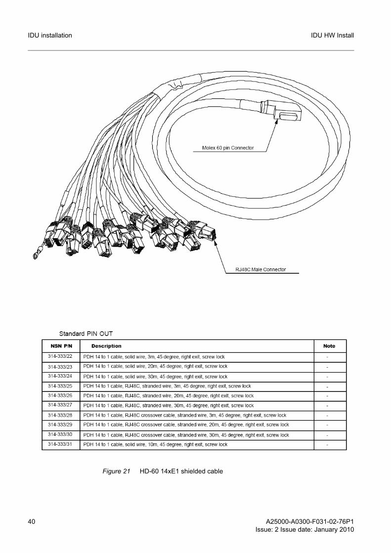
Figure 21 HD-60 14xE1 shielded cable
A25000-A0300-F031-02-76P1Issue: 2 Issue date: January 2010
41
IDU HW Install IDU installation
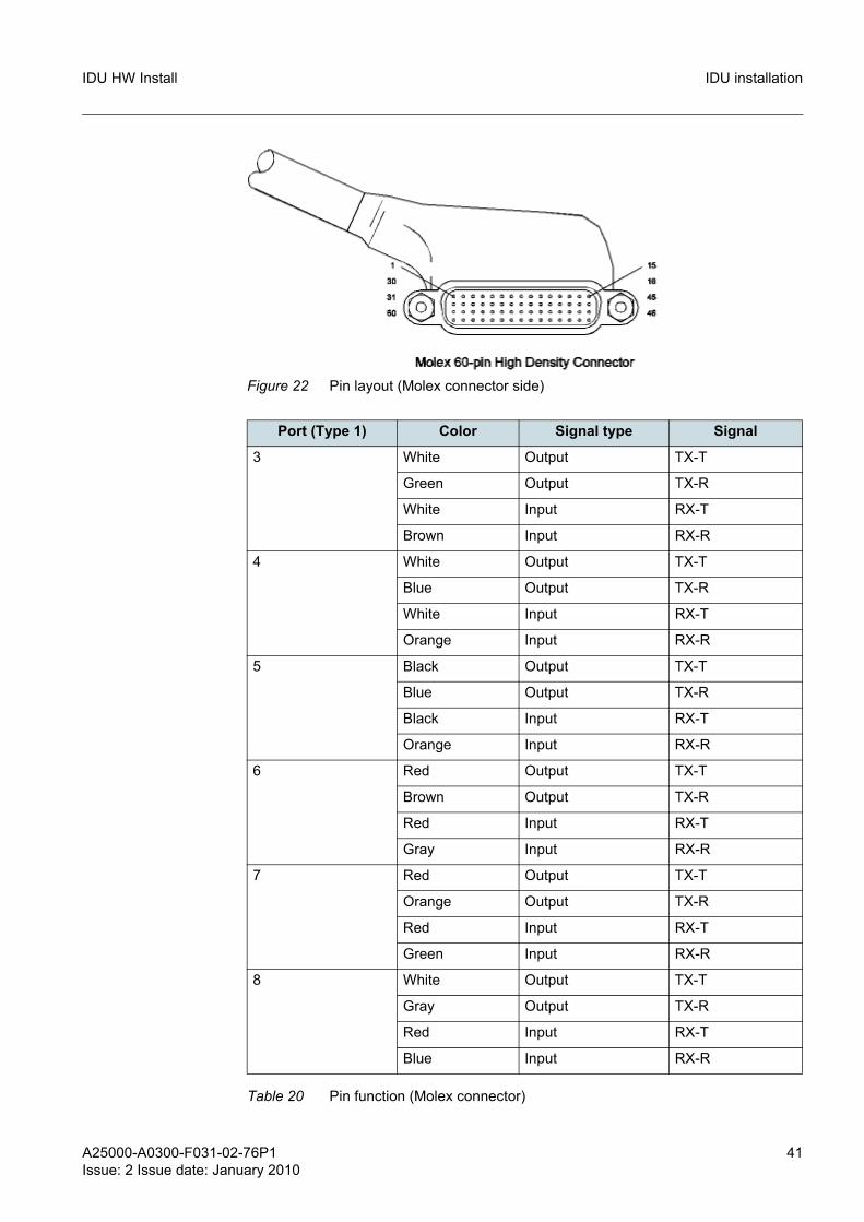
Figure 22 Pin layout (Molex connector side)
Port (Type 1) Color Signal type Signal
3 White Output TX-T
Green Output TX-R
White Input RX-T
Brown Input RX-R
4 White Output TX-T
Blue Output TX-R
White Input RX-T
Orange Input RX-R
5 Black Output TX-T
Blue Output TX-R
Black Input RX-T
Orange Input RX-R
6 Red Output TX-T
Brown Output TX-R
Red Input RX-T
Gray Input RX-R
7 Red Output TX-T
Orange Output TX-R
Red Input RX-T
Green Input RX-R
8 White Output TX-T
Gray Output TX-R
Red Input RX-T
Blue Input RX-R
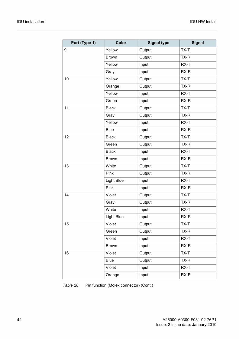
Table 20 Pin function (Molex connector)
42 A25000-A0300-F031-02-76P1Issue: 2 Issue date: January 2010
IDU HW InstallIDU installation
9 Yellow Output TX-T
Brown Output TX-R
Yellow Input RX-T
Gray Input RX-R
10 Yellow Output TX-T
Orange Output TX-R
Yellow Input RX-T
Green Input RX-R
11 Black Output TX-T
Gray Output TX-R
Yellow Input RX-T
Blue Input RX-R
12 Black Output TX-T
Green Output TX-R
Black Input RX-T
Brown Input RX-R
13 White Output TX-T
Pink Output TX-R
Light Blue Input RX-T
Pink Input RX-R
14 Violet Output TX-T
Gray Output TX-R
White Input RX-T
Light Blue Input RX-R
15 Violet Output TX-T
Green Output TX-R
Violet Input RX-T
Brown Input RX-R
16 Violet Output TX-T
Blue Output TX-R
Violet Input RX-T
Orange Input RX-R
Port (Type 1) Color Signal type Signal
Table 20 Pin function (Molex connector) (Cont.)
A25000-A0300-F031-02-76P1Issue: 2 Issue date: January 2010
43
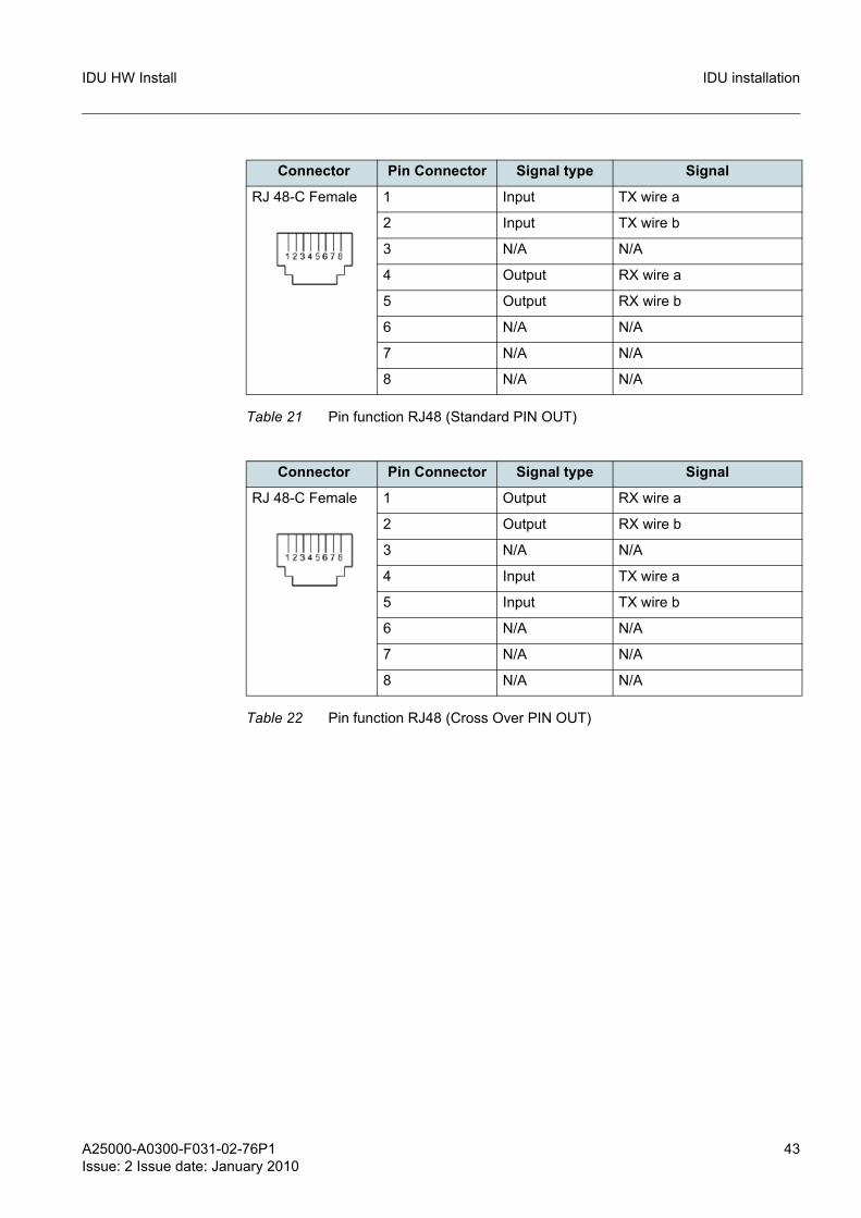
IDU HW Install IDU installation
Connector Pin Connector Signal type Signal
RJ 48-C Female 1 Input TX wire a
2 Input TX wire b
3 N/A N/A
4 Output RX wire a
5 Output RX wire b
6 N/A N/A
7 N/A N/A
8 N/A N/A
Table 21 Pin function RJ48 (Standard PIN OUT)
Connector Pin Connector Signal type Signal
RJ 48-C Female 1 Output RX wire a
2 Output RX wire b
3 N/A N/A
4 Input TX wire a
5 Input TX wire b
6 N/A N/A
7 N/A N/A
8 N/A N/A
Table 22 Pin function RJ48 (Cross Over PIN OUT)
44 A25000-A0300-F031-02-76P1Issue: 2 Issue date: January 2010
IDU HW InstallIDU installation
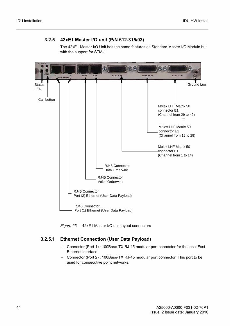
3.2.5 42xE1 Master I/O unit (P/N 612-315/03)The 42xE1 Master I/O Unit has the same features as Standard Master I/O Module but with the support for STM-1.
Figure 23 42xE1 Master I/O unit layout connectors
3.2.5.1 Ethernet Connection (User Data Payload)– Connector (Port 1) : 100Base-TX RJ-45 modular port connector for the local Fast
Ethernet interface.– Connector (Port 2) : 100Base-TX RJ-45 modular port connector. This port to be
used for consecutive point networks.
Status LED
RJ45 ConnectorPort (2) Ethernet (User Data Payload)
Molex LHF Matrix 50connector E1(Channel from 1 to 14)
Ground Lug
Call button
RJ45 ConnectorPort (1) Ethernet (User Data Payload)
RJ45 Connector Voice Orderwire
RJ45 Connector Data Orderwire
Molex LHF Matrix 50connector E1(Channel from 15 to 28)
Molex LHF Matrix 50connector E1(Channel from 29 to 42)
A25000-A0300-F031-02-76P1Issue: 2 Issue date: January 2010
45
IDU HW Install IDU installation
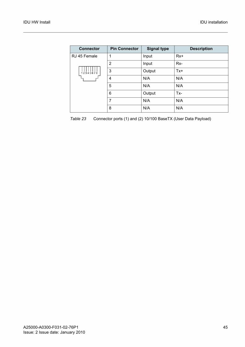
Connector Pin Connector Signal type Description
RJ 45 Female 1 Input Rx+
2 Input Rx-
3 Output Tx+
4 N/A N/A
5 N/A N/A
6 Output Tx-
7 N/A N/A
8 N/A N/A
Table 23 Connector ports (1) and (2) 10/100 BaseTX (User Data Payload)
46 A25000-A0300-F031-02-76P1Issue: 2 Issue date: January 2010
IDU HW InstallIDU installation
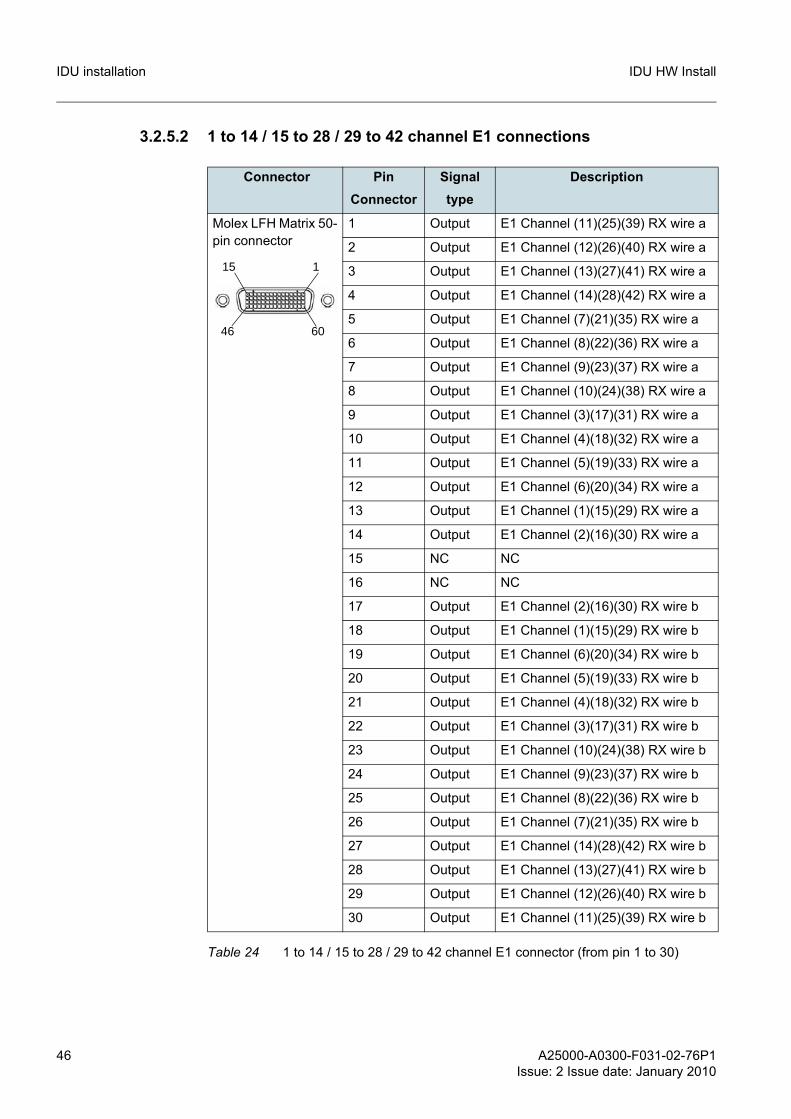
3.2.5.2 1 to 14 / 15 to 28 / 29 to 42 channel E1 connections
Connector Pin Connector
Signal type
Description
Molex LFH Matrix 50-pin connector
1 Output E1 Channel (11)(25)(39) RX wire a
2 Output E1 Channel (12)(26)(40) RX wire a
3 Output E1 Channel (13)(27)(41) RX wire a
4 Output E1 Channel (14)(28)(42) RX wire a
5 Output E1 Channel (7)(21)(35) RX wire a
6 Output E1 Channel (8)(22)(36) RX wire a
7 Output E1 Channel (9)(23)(37) RX wire a
8 Output E1 Channel (10)(24)(38) RX wire a
9 Output E1 Channel (3)(17)(31) RX wire a
10 Output E1 Channel (4)(18)(32) RX wire a
11 Output E1 Channel (5)(19)(33) RX wire a
12 Output E1 Channel (6)(20)(34) RX wire a
13 Output E1 Channel (1)(15)(29) RX wire a
14 Output E1 Channel (2)(16)(30) RX wire a
15 NC NC
16 NC NC
17 Output E1 Channel (2)(16)(30) RX wire b
18 Output E1 Channel (1)(15)(29) RX wire b
19 Output E1 Channel (6)(20)(34) RX wire b
20 Output E1 Channel (5)(19)(33) RX wire b
21 Output E1 Channel (4)(18)(32) RX wire b
22 Output E1 Channel (3)(17)(31) RX wire b
23 Output E1 Channel (10)(24)(38) RX wire b
24 Output E1 Channel (9)(23)(37) RX wire b
25 Output E1 Channel (8)(22)(36) RX wire b
26 Output E1 Channel (7)(21)(35) RX wire b
27 Output E1 Channel (14)(28)(42) RX wire b
28 Output E1 Channel (13)(27)(41) RX wire b
29 Output E1 Channel (12)(26)(40) RX wire b
30 Output E1 Channel (11)(25)(39) RX wire b
Table 24 1 to 14 / 15 to 28 / 29 to 42 channel E1 connector (from pin 1 to 30)
1
60
15
46
A25000-A0300-F031-02-76P1Issue: 2 Issue date: January 2010
47
IDU HW Install IDU installation
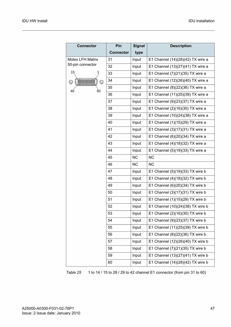
Connector Pin Connector
Signal type
Description
Molex LFH Matrix 50-pin connector
31 Input E1 Channel (14)(28)(42) TX wire a
32 Input E1 Channel (13)(27)(41) TX wire a
33 Input E1 Channel (7)(21)(35) TX wire a
34 Input E1 Channel (12)(26)(40) TX wire a
35 Input E1 Channel (8)(22)(36) TX wire a
36 Input E1 Channel (11)(25)(39) TX wire a
37 Input E1 Channel (9)(23)(37) TX wire a
38 Input E1 Channel (2)(16)(30) TX wire a
39 Input E1 Channel (10)(24)(38) TX wire a
40 Input E1 Channel (1)(15)(29) TX wire a
41 Input E1 Channel (3)(17)(31) TX wire a
42 Input E1 Channel (6)(20)(34) TX wire a
43 Input E1 Channel (4)(18)(32) TX wire a
44 Input E1 Channel (5)(19)(33) TX wire a
45 NC NC
46 NC NC
47 Input E1 Channel (5)(19)(33) TX wire b
48 Input E1 Channel (4)(18)(32) TX wire b
49 Input E1 Channel (6)(20)(34) TX wire b
50 Input E1 Channel (3)(17)(31) TX wire b
51 Input E1 Channel (1)(15)(29) TX wire b
52 Input E1 Channel (10)(24)(38) TX wire b
53 Input E1 Channel (2)(16)(30) TX wire b
54 Input E1 Channel (9)(23)(37) TX wire b
55 Input E1 Channel (11)(25)(39) TX wire b
56 Input E1 Channel (8)(22)(36) TX wire b
57 Input E1 Channel (12)(26)(40) TX wire b
58 Input E1 Channel (7)(21)(35) TX wire b
59 Input E1 Channel (13)(27)(41) TX wire b
60 Input E1 Channel (14)(28)(42) TX wire b
Table 25 1 to 14 / 15 to 28 / 29 to 42 channel E1 connector (from pin 31 to 60)
1
60
15
46

48 A25000-A0300-F031-02-76P1Issue: 2 Issue date: January 2010
IDU HW InstallIDU installation
Figure 24 HD-60 14xE1 shielded cable
A25000-A0300-F031-02-76P1Issue: 2 Issue date: January 2010
49
IDU HW Install IDU installation
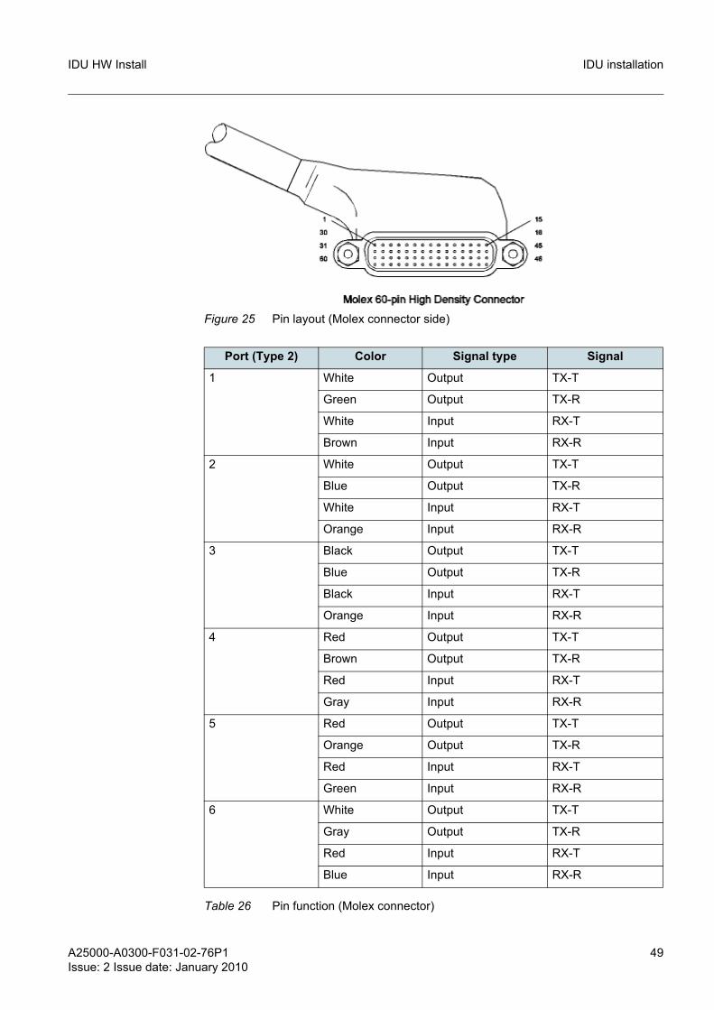
Figure 25 Pin layout (Molex connector side)
Port (Type 2) Color Signal type Signal
1 White Output TX-T
Green Output TX-R
White Input RX-T
Brown Input RX-R
2 White Output TX-T
Blue Output TX-R
White Input RX-T
Orange Input RX-R
3 Black Output TX-T
Blue Output TX-R
Black Input RX-T
Orange Input RX-R
4 Red Output TX-T
Brown Output TX-R
Red Input RX-T
Gray Input RX-R
5 Red Output TX-T
Orange Output TX-R
Red Input RX-T
Green Input RX-R
6 White Output TX-T
Gray Output TX-R
Red Input RX-T
Blue Input RX-R
Table 26 Pin function (Molex connector)
50 A25000-A0300-F031-02-76P1Issue: 2 Issue date: January 2010
IDU HW InstallIDU installation
7 Yellow Output TX-T
Brown Output TX-R
Yellow Input RX-T
Gray Input RX-R
8 Yellow Output TX-T
Orange Output TX-R
Yellow Input RX-T
Green Input RX-R
9 Black Output TX-T
Gray Output TX-R
Yellow Input RX-T
Blue Input RX-R
10 Black Output TX-T
Green Output TX-R
Black Input RX-T
Brown Input RX-R
11 White Output TX-T
Pink Output TX-R
Light Blue Input RX-T
Pink Input RX-R
12 Violet Output TX-T
Gray Output TX-R
White Input RX-T
Light Blue Input RX-R
13 Violet Output TX-T
Green Output TX-R
Violet Input RX-T
Brown Input RX-R
14 Violet Output TX-T
Blue Output TX-R
Violet Input RX-T
Orange Input RX-R
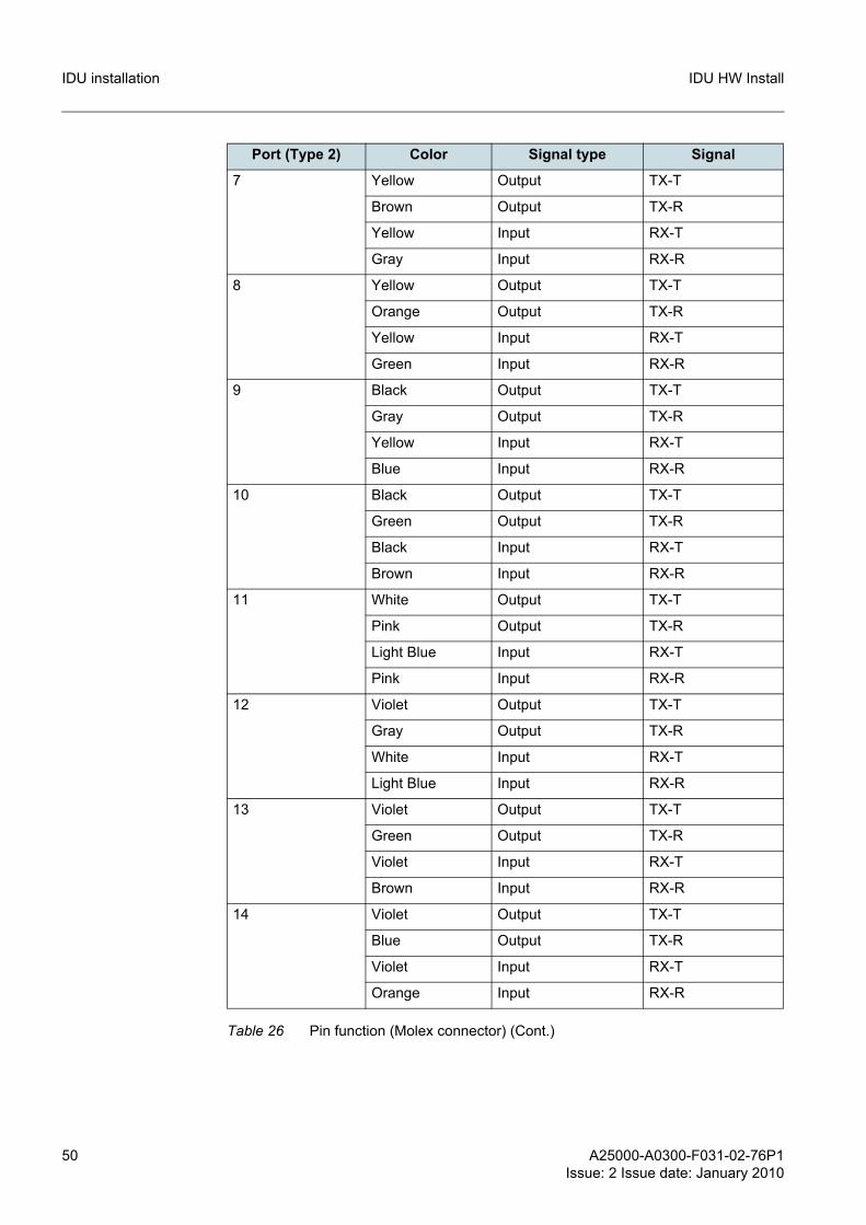
Port (Type 2) Color Signal type Signal
Table 26 Pin function (Molex connector) (Cont.)

A25000-A0300-F031-02-76P1Issue: 2 Issue date: January 2010
51
IDU HW Install IDU installation
3.2.5.3 Voice Orderwire connection
Connector Pin Connector Signal type Signal
RJ 48-C Female 1 Input TX wire a
2 Input TX wire b
3 N/A N/A
4 Output RX wire a
5 Output RX wire b
6 N/A N/A
7 N/A N/A
8 N/A N/A
Table 27 Pin function RJ48 (Standard PIN OUT)
Connector Pin Connector Signal type Signal
RJ 48-C Female 1 Output RX wire a
2 Output RX wire b
3 N/A N/A
4 Input TX wire a
5 Input TX wire b
6 N/A N/A
7 N/A N/A
8 N/A N/A
Table 28 Pin function RJ48 (Cross Over PIN OUT)
Connector Pin Connector Signal type Description
RJ 45 Female 1 N/A NC
2 Input PTT
3 N/A GROUND
4 Output PO-
5 Output PO+
6 Input TI-
7 N/A GROUND
8 N/A NC
Table 29 Voice Orderwire connector
52 A25000-A0300-F031-02-76P1Issue: 2 Issue date: January 2010
IDU HW InstallIDU installation
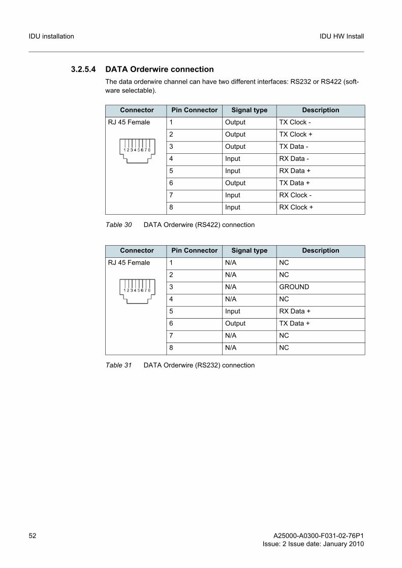
3.2.5.4 DATA Orderwire connection The data orderwire channel can have two different interfaces: RS232 or RS422 (soft-ware selectable).
Connector Pin Connector Signal type Description
RJ 45 Female 1 Output TX Clock -
2 Output TX Clock +
3 Output TX Data -
4 Input RX Data -
5 Input RX Data +
6 Output TX Data +
7 Input RX Clock -
8 Input RX Clock +
Table 30 DATA Orderwire (RS422) connection
Connector Pin Connector Signal type Description
RJ 45 Female 1 N/A NC
2 N/A NC
3 N/A GROUND
4 N/A NC
5 Input RX Data +
6 Output TX Data +
7 N/A NC
8 N/A NC
Table 31 DATA Orderwire (RS232) connection
A25000-A0300-F031-02-76P1Issue: 2 Issue date: January 2010
53
IDU HW Install IDU installation
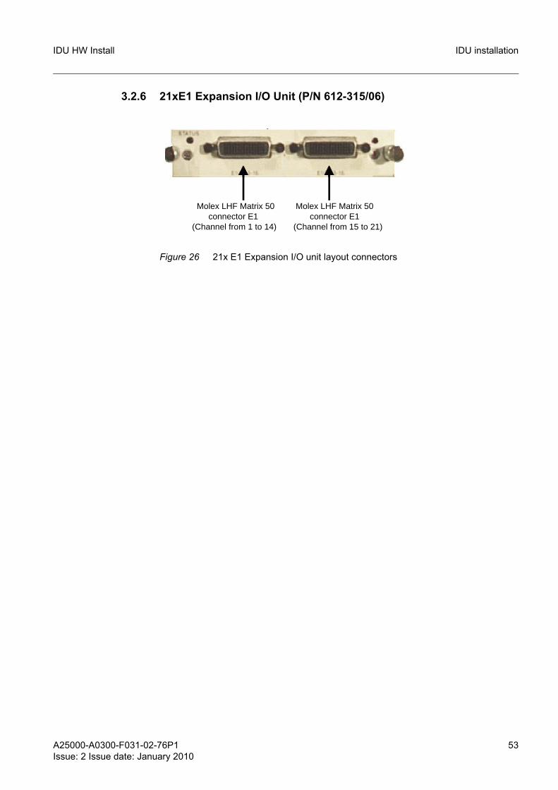
3.2.6 21xE1 Expansion I/O Unit (P/N 612-315/06)
Figure 26 21x E1 Expansion I/O unit layout connectors
Molex LHF Matrix 50connector E1
(Channel from 15 to 21)
Molex LHF Matrix 50connector E1
(Channel from 1 to 14)
54 A25000-A0300-F031-02-76P1Issue: 2 Issue date: January 2010
IDU HW InstallIDU installation
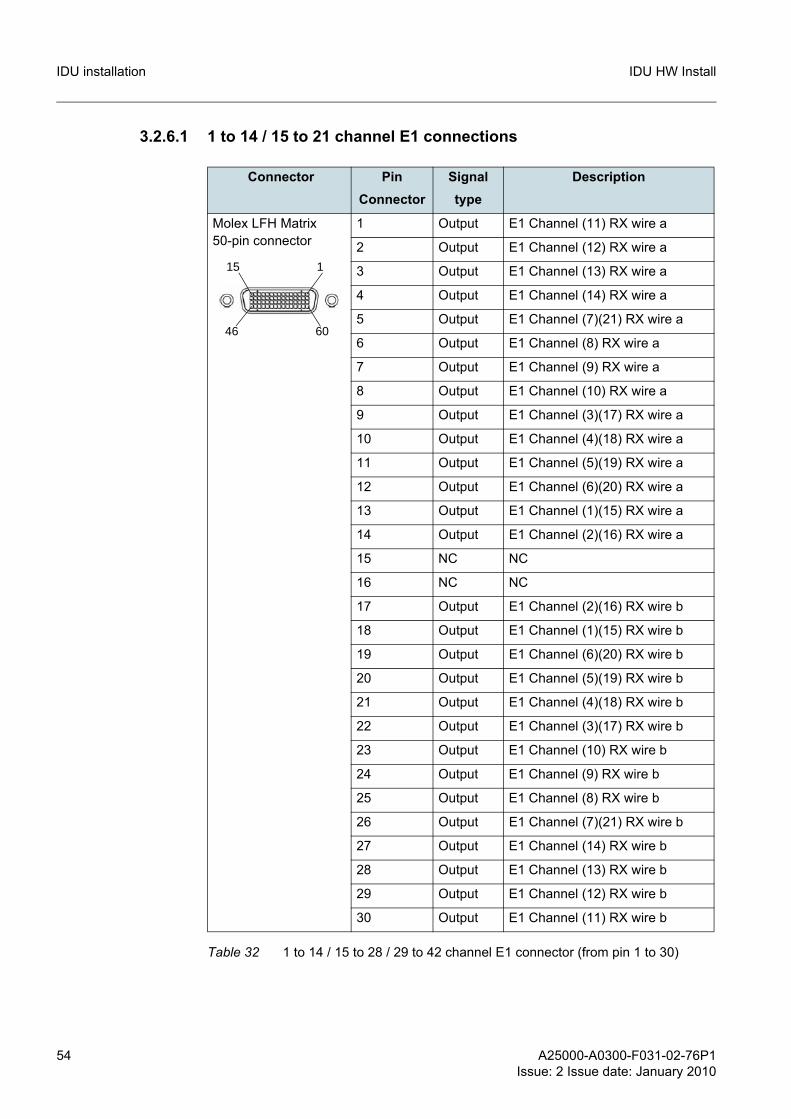
3.2.6.1 1 to 14 / 15 to 21 channel E1 connections
Connector Pin Connector
Signal type
Description
Molex LFH Matrix 50-pin connector
1 Output E1 Channel (11) RX wire a
2 Output E1 Channel (12) RX wire a
3 Output E1 Channel (13) RX wire a
4 Output E1 Channel (14) RX wire a
5 Output E1 Channel (7)(21) RX wire a
6 Output E1 Channel (8) RX wire a
7 Output E1 Channel (9) RX wire a
8 Output E1 Channel (10) RX wire a
9 Output E1 Channel (3)(17) RX wire a
10 Output E1 Channel (4)(18) RX wire a
11 Output E1 Channel (5)(19) RX wire a
12 Output E1 Channel (6)(20) RX wire a
13 Output E1 Channel (1)(15) RX wire a
14 Output E1 Channel (2)(16) RX wire a
15 NC NC
16 NC NC
17 Output E1 Channel (2)(16) RX wire b
18 Output E1 Channel (1)(15) RX wire b
19 Output E1 Channel (6)(20) RX wire b
20 Output E1 Channel (5)(19) RX wire b
21 Output E1 Channel (4)(18) RX wire b
22 Output E1 Channel (3)(17) RX wire b
23 Output E1 Channel (10) RX wire b
24 Output E1 Channel (9) RX wire b
25 Output E1 Channel (8) RX wire b
26 Output E1 Channel (7)(21) RX wire b
27 Output E1 Channel (14) RX wire b
28 Output E1 Channel (13) RX wire b
29 Output E1 Channel (12) RX wire b
30 Output E1 Channel (11) RX wire b
Table 32 1 to 14 / 15 to 28 / 29 to 42 channel E1 connector (from pin 1 to 30)
1
60
15
46
A25000-A0300-F031-02-76P1Issue: 2 Issue date: January 2010
55
IDU HW Install IDU installation
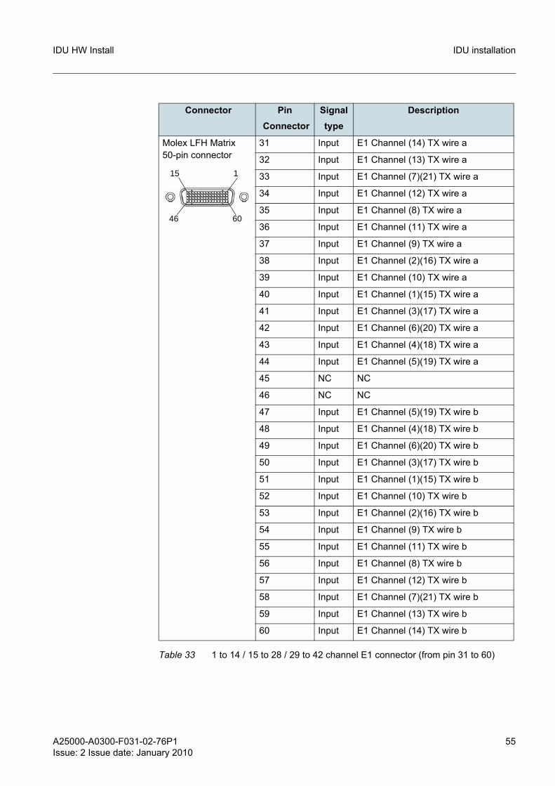
Connector Pin Connector
Signal type
Description
Molex LFH Matrix 50-pin connector
31 Input E1 Channel (14) TX wire a
32 Input E1 Channel (13) TX wire a
33 Input E1 Channel (7)(21) TX wire a
34 Input E1 Channel (12) TX wire a
35 Input E1 Channel (8) TX wire a
36 Input E1 Channel (11) TX wire a
37 Input E1 Channel (9) TX wire a
38 Input E1 Channel (2)(16) TX wire a
39 Input E1 Channel (10) TX wire a
40 Input E1 Channel (1)(15) TX wire a
41 Input E1 Channel (3)(17) TX wire a
42 Input E1 Channel (6)(20) TX wire a
43 Input E1 Channel (4)(18) TX wire a
44 Input E1 Channel (5)(19) TX wire a
45 NC NC
46 NC NC
47 Input E1 Channel (5)(19) TX wire b
48 Input E1 Channel (4)(18) TX wire b
49 Input E1 Channel (6)(20) TX wire b
50 Input E1 Channel (3)(17) TX wire b
51 Input E1 Channel (1)(15) TX wire b
52 Input E1 Channel (10) TX wire b
53 Input E1 Channel (2)(16) TX wire b
54 Input E1 Channel (9) TX wire b
55 Input E1 Channel (11) TX wire b
56 Input E1 Channel (8) TX wire b
57 Input E1 Channel (12) TX wire b
58 Input E1 Channel (7)(21) TX wire b
59 Input E1 Channel (13) TX wire b
60 Input E1 Channel (14) TX wire b
Table 33 1 to 14 / 15 to 28 / 29 to 42 channel E1 connector (from pin 31 to 60)
1
60
15
46

56 A25000-A0300-F031-02-76P1Issue: 2 Issue date: January 2010
IDU HW InstallIDU installation
Figure 27 HD-60 14xE1 shielded cable
A25000-A0300-F031-02-76P1Issue: 2 Issue date: January 2010
57
IDU HW Install IDU installation
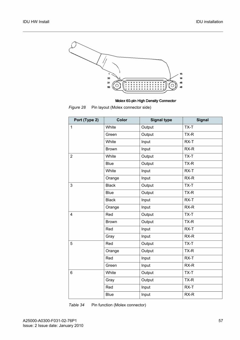
Figure 28 Pin layout (Molex connector side)
Port (Type 2) Color Signal type Signal
1 White Output TX-T
Green Output TX-R
White Input RX-T
Brown Input RX-R
2 White Output TX-T
Blue Output TX-R
White Input RX-T
Orange Input RX-R
3 Black Output TX-T
Blue Output TX-R
Black Input RX-T
Orange Input RX-R
4 Red Output TX-T
Brown Output TX-R
Red Input RX-T
Gray Input RX-R
5 Red Output TX-T
Orange Output TX-R
Red Input RX-T
Green Input RX-R
6 White Output TX-T
Gray Output TX-R
Red Input RX-T
Blue Input RX-R
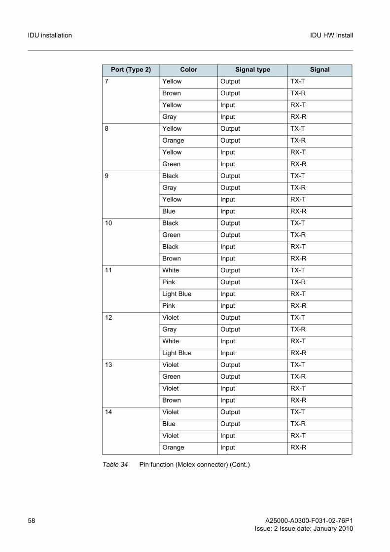
Table 34 Pin function (Molex connector)
58 A25000-A0300-F031-02-76P1Issue: 2 Issue date: January 2010
IDU HW InstallIDU installation
7 Yellow Output TX-T
Brown Output TX-R
Yellow Input RX-T
Gray Input RX-R
8 Yellow Output TX-T
Orange Output TX-R
Yellow Input RX-T
Green Input RX-R
9 Black Output TX-T
Gray Output TX-R
Yellow Input RX-T
Blue Input RX-R
10 Black Output TX-T
Green Output TX-R
Black Input RX-T
Brown Input RX-R
11 White Output TX-T
Pink Output TX-R
Light Blue Input RX-T
Pink Input RX-R
12 Violet Output TX-T
Gray Output TX-R
White Input RX-T
Light Blue Input RX-R
13 Violet Output TX-T
Green Output TX-R
Violet Input RX-T
Brown Input RX-R
14 Violet Output TX-T
Blue Output TX-R
Violet Input RX-T
Orange Input RX-R
Port (Type 2) Color Signal type Signal
Table 34 Pin function (Molex connector) (Cont.)

A25000-A0300-F031-02-76P1Issue: 2 Issue date: January 2010
59
IDU HW Install IDU installation
Connector Pin Connector Signal type Signal
RJ 48-C Female 1 Input TX wire a
2 Input TX wire b
3 N/A N/A
4 Output RX wire a
5 Output RX wire b
6 N/A N/A
7 N/A N/A
8 N/A N/A
Table 35 Pin function RJ48 (Standard PIN OUT)
Connector Pin Connector Signal type Signal
RJ 48-C Female 1 Output RX wire a
2 Output RX wire b
3 N/A N/A
4 Input TX wire a
5 Input TX wire b
6 N/A N/A
7 N/A N/A
8 N/A N/A
Table 36 Pin function RJ48 (Cross Over PIN OUT)
60 A25000-A0300-F031-02-76P1Issue: 2 Issue date: January 2010
IDU HW InstallIDU installation
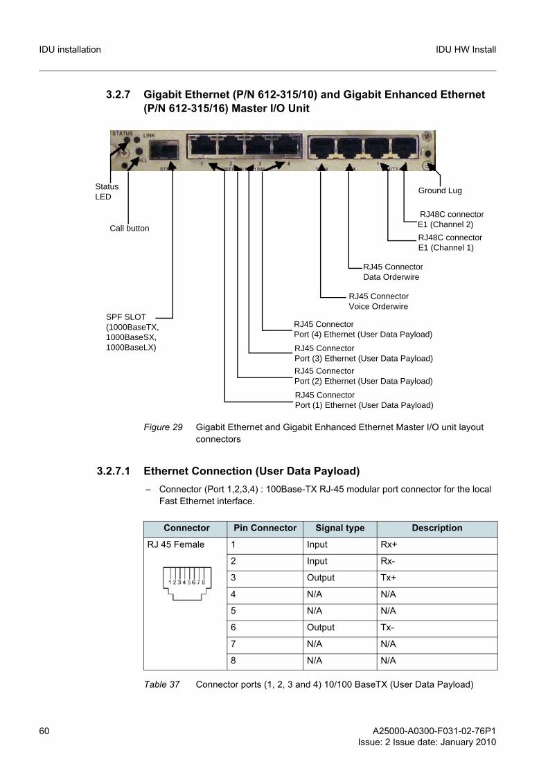
3.2.7 Gigabit Ethernet (P/N 612-315/10) and Gigabit Enhanced Ethernet (P/N 612-315/16) Master I/O Unit
Figure 29 Gigabit Ethernet and Gigabit Enhanced Ethernet Master I/O unit layout connectors
3.2.7.1 Ethernet Connection (User Data Payload)– Connector (Port 1,2,3,4) : 100Base-TX RJ-45 modular port connector for the local
Fast Ethernet interface.
SPF SLOT(1000BaseTX,1000BaseSX, 1000BaseLX)
Status LED
RJ45 ConnectorPort (4) Ethernet (User Data Payload)
Ground Lug
RJ45 ConnectorPort (3) Ethernet (User Data Payload)
RJ45 Connector Voice Orderwire
RJ45 Connector Data Orderwire
RJ48C connectorE1 (Channel 1)
RJ48C connectorE1 (Channel 2)
RJ45 ConnectorPort (2) Ethernet (User Data Payload)
RJ45 ConnectorPort (1) Ethernet (User Data Payload)
Call button
Connector Pin Connector Signal type Description
RJ 45 Female 1 Input Rx+
2 Input Rx-
3 Output Tx+
4 N/A N/A
5 N/A N/A
6 Output Tx-
7 N/A N/A
8 N/A N/A
Table 37 Connector ports (1, 2, 3 and 4) 10/100 BaseTX (User Data Payload)
A25000-A0300-F031-02-76P1Issue: 2 Issue date: January 2010
61
IDU HW Install IDU installation
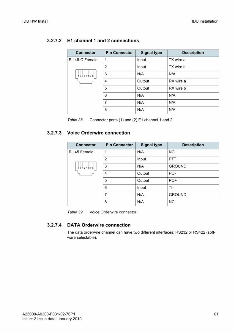
3.2.7.2 E1 channel 1 and 2 connections
3.2.7.3 Voice Orderwire connection
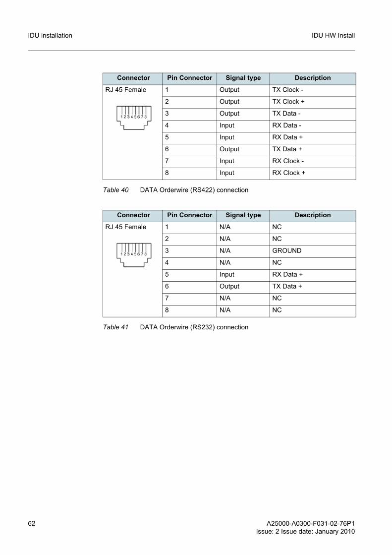
3.2.7.4 DATA Orderwire connectionThe data orderwire channel can have two different interfaces: RS232 or RS422 (soft-ware selectable).
Connector Pin Connector Signal type Description
RJ 48-C Female 1 Input TX wire a
2 Input TX wire b
3 N/A N/A
4 Output RX wire a
5 Output RX wire b
6 N/A N/A
7 N/A N/A
8 N/A N/A
Table 38 Connector ports (1) and (2) E1 channel 1 and 2
Connector Pin Connector Signal type Description
RJ 45 Female 1 N/A NC
2 Input PTT
3 N/A GROUND
4 Output PO-
5 Output PO+
6 Input TI-
7 N/A GROUND
8 N/A NC
Table 39 Voice Orderwire connector
62 A25000-A0300-F031-02-76P1Issue: 2 Issue date: January 2010
IDU HW InstallIDU installation
Connector Pin Connector Signal type Description
RJ 45 Female 1 Output TX Clock -
2 Output TX Clock +
3 Output TX Data -
4 Input RX Data -
5 Input RX Data +
6 Output TX Data +
7 Input RX Clock -
8 Input RX Clock +
Table 40 DATA Orderwire (RS422) connection
Connector Pin Connector Signal type Description
RJ 45 Female 1 N/A NC
2 N/A NC
3 N/A GROUND
4 N/A NC
5 Input RX Data +
6 Output TX Data +
7 N/A NC
8 N/A NC
Table 41 DATA Orderwire (RS232) connection
A25000-A0300-F031-02-76P1Issue: 2 Issue date: January 2010
63
IDU HW Install IDU installation
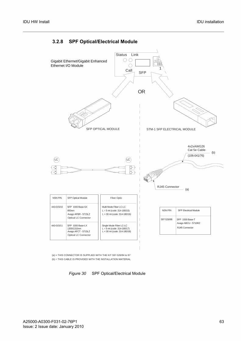
3.2.8 SPF Optical/Electrical Module
Figure 30 SPF Optical/Electrical Module
SFP 1000 Base-SX
850nm
SFP 1000 Base-LX1300/1310nm
STM-1 SFP ELECTRICAL MODULESFP OPTICAL MODULE
Avago AFCT - 5715LZ
RJ45 Connector
Avago ABCU - 5710RZ
SFP 1000 Base-T
Avago AFBR - 5715LZ
Optical LC Connector
Optical LC Connector
SFPCall
Status Link
1
Gigabit Ethernet I/O Module
443-015/10
443-015/11
L = 30 mt (code: 314-180/16)
Multi Mode Fiber LC-LC
L = 30 mt (code: 314-180/18)L = 5 mt (code: 314-180/17)Single Mode Fiber LC-LC
L = 5 mt (code: 314-180/15)
NSN P/N SFP Optical Module Fiber Optic
(a) = THIS CONNECTOR IS SUPPLIED WITH THE KIT 597-526/94 to 97
(b) = THIS CABLE IS PROVIDED WITH THE INSTALLATION MATERIAL
RJ45 Connector
(a)
Cat 5e Cable
(106-041/76)
4x2xAWG26
(b)
SFP Electrical Module
597-526/98
NSN P/N
LC LC
OR
Gigabit Ethernet/Gigabit Enhanced Ethernet I/O Module
64 A25000-A0300-F031-02-76P1Issue: 2 Issue date: January 2010
IDU HW InstallIDU installation
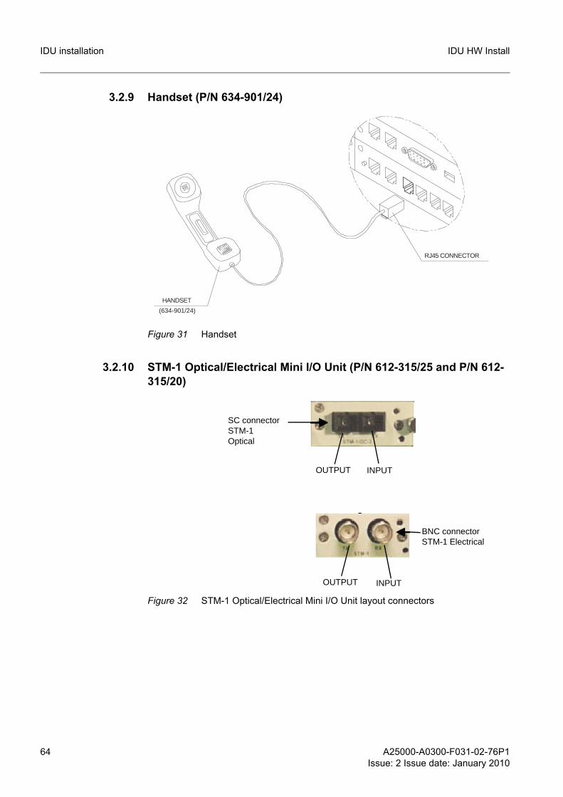
3.2.9 Handset (P/N 634-901/24)
Figure 31 Handset
3.2.10 STM-1 Optical/Electrical Mini I/O Unit (P/N 612-315/25 and P/N 612-315/20)
Figure 32 STM-1 Optical/Electrical Mini I/O Unit layout connectors
RJ45 CONNECTOR
HANDSET
(634-901/24)
BNC connectorSTM-1 Electrical
SC connectorSTM-1Optical
OUTPUT INPUT
OUTPUT INPUT
A25000-A0300-F031-02-76P1Issue: 2 Issue date: January 2010
65
IDU HW Install IDU installation
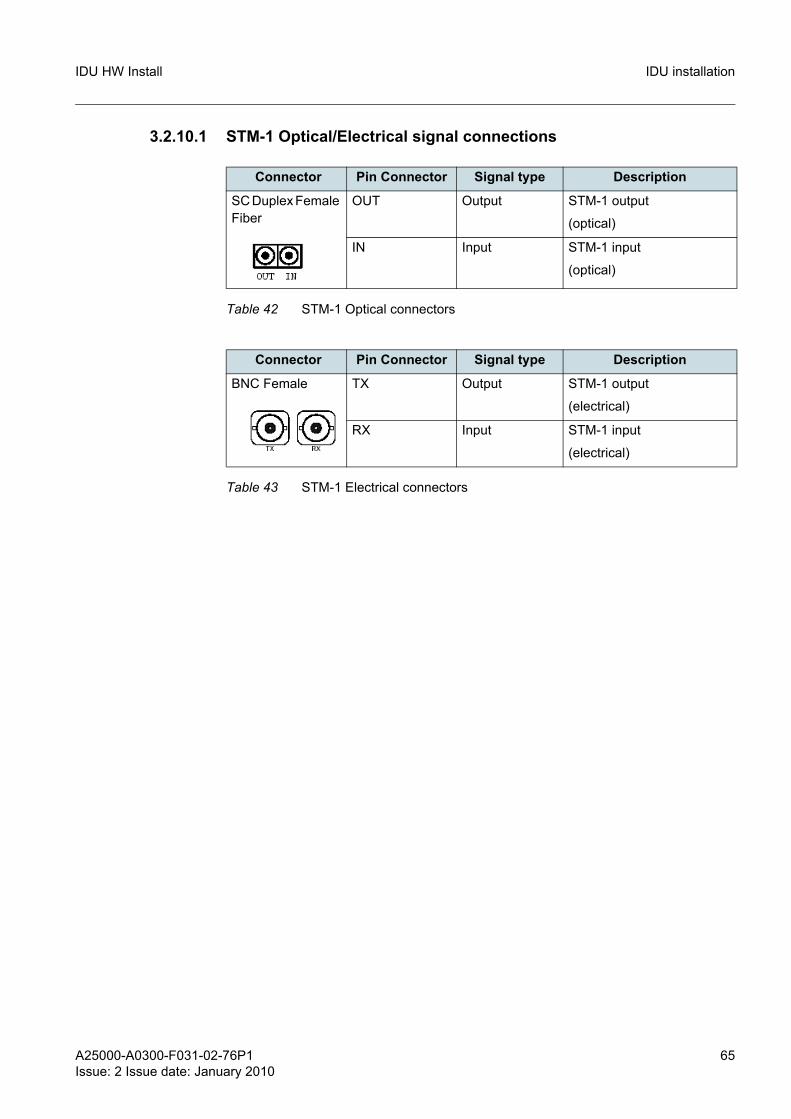
3.2.10.1 STM-1 Optical/Electrical signal connections
Connector Pin Connector Signal type Description
SC Duplex Female Fiber
OUT Output STM-1 output
(optical)
IN Input STM-1 input
(optical)
Table 42 STM-1 Optical connectors
Connector Pin Connector Signal type Description
BNC Female TX Output STM-1 output
(electrical)
RX Input STM-1 input
(electrical)
Table 43 STM-1 Electrical connectors
66 A25000-A0300-F031-02-76P1Issue: 2 Issue date: January 2010
IDU HW InstallIDU installation
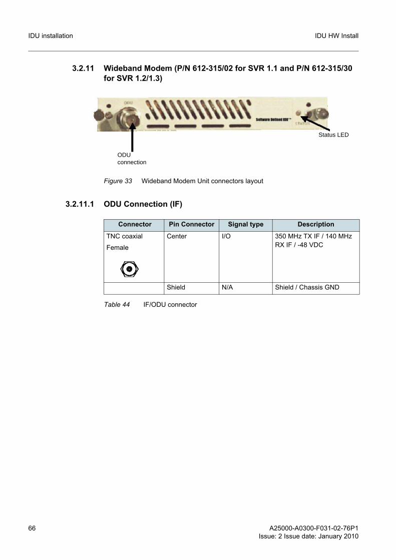
3.2.11 Wideband Modem (P/N 612-315/02 for SVR 1.1 and P/N 612-315/30 for SVR 1.2/1.3)
Figure 33 Wideband Modem Unit connectors layout
3.2.11.1 ODU Connection (IF)
ODUconnection
Status LED
Connector Pin Connector Signal type Description
TNC coaxial
Female
Center I/O 350 MHz TX IF / 140 MHz RX IF / -48 VDC
Shield N/A Shield / Chassis GND
Table 44 IF/ODU connector
A25000-A0300-F031-02-76P1Issue: 2 Issue date: January 2010
67
IDU HW Install Patch Panel installation
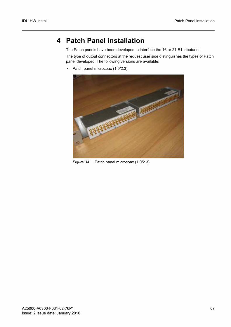
4 Patch Panel installationThe Patch panels have been developed to interface the 16 or 21 E1 tributaries.
The type of output connectors at the request user side distinguishes the types of Patch panel developed. The following versions are available:
• Patch panel microcoax (1.0/2.3)
Figure 34 Patch panel microcoax (1.0/2.3)
68 A25000-A0300-F031-02-76P1Issue: 2 Issue date: January 2010
IDU HW InstallPatch Panel installation
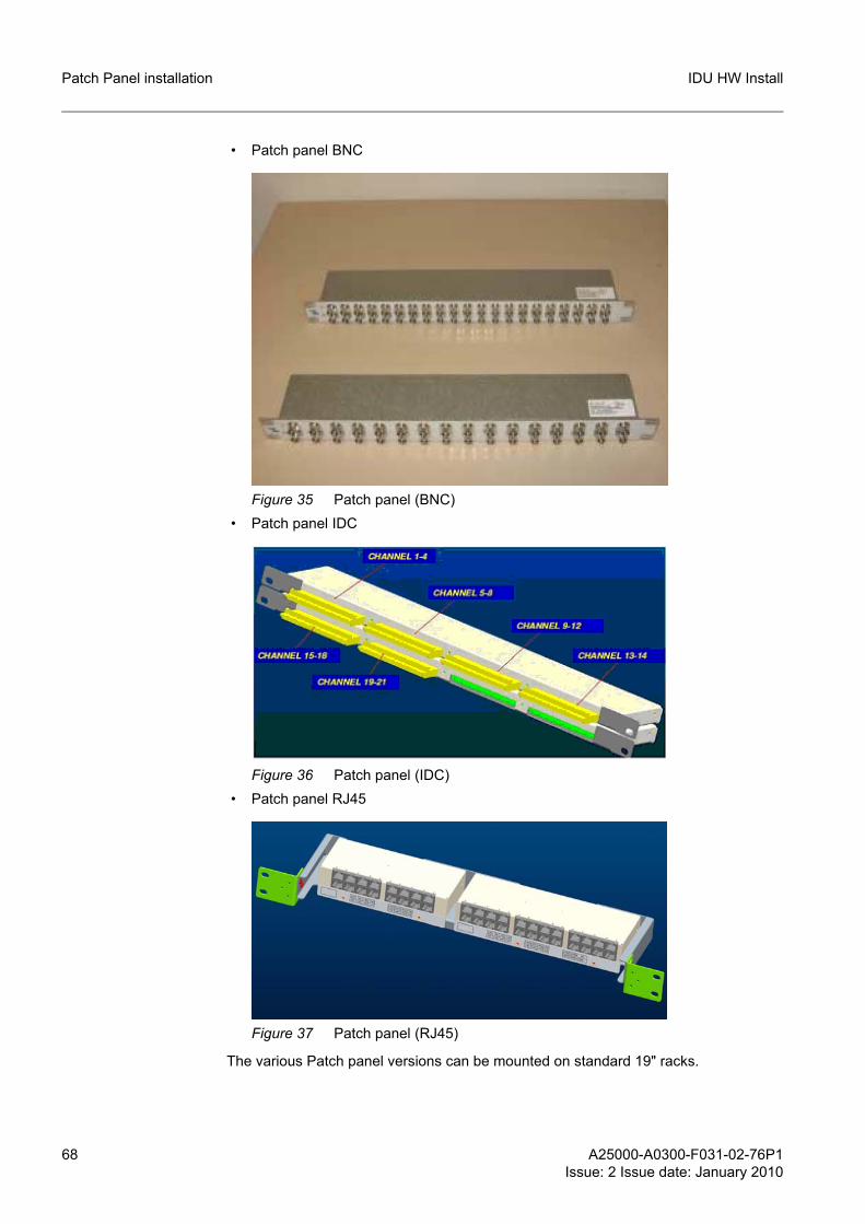
• Patch panel BNC
Figure 35 Patch panel (BNC) • Patch panel IDC
Figure 36 Patch panel (IDC) • Patch panel RJ45
Figure 37 Patch panel (RJ45)
The various Patch panel versions can be mounted on standard 19" racks.
A25000-A0300-F031-02-76P1Issue: 2 Issue date: January 2010
69
IDU HW Install Patch Panel installation
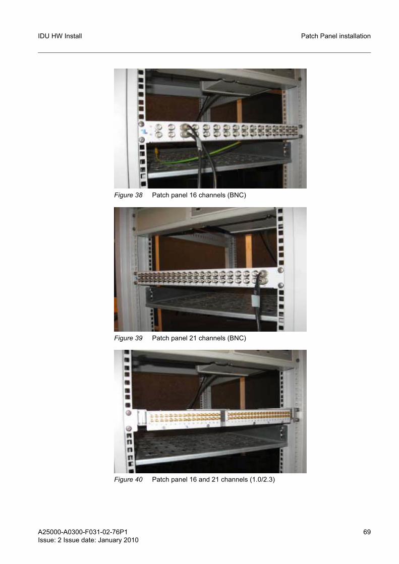
Figure 38 Patch panel 16 channels (BNC)
Figure 39 Patch panel 21 channels (BNC)
Figure 40 Patch panel 16 and 21 channels (1.0/2.3)
70 A25000-A0300-F031-02-76P1Issue: 2 Issue date: January 2010
IDU HW InstallPatch Panel installation
g All types of Patch panels are provided at the back with a faston-female terminated ground cord which must be connected to the fastons on the ground bars of the racks.
4.1 BNC patch panelsThese Patch panels, both in the 16 and 21 channel version, can be installed in the 19" rack with 4 caged nuts and M6 standard screws.
4.2 1.0/2.3 and RJ45 patch panelsThese patch panels need a mechanical support for fastening to the rack (frame).
Figure 41 Frame for 1.0/2.3 and RJ45 connector Patch panel
The bottom plate of the frame is provided with slits housing the fastening tabs present on the Patch panels.
The 1.0/2.3 connector Patch panel are provided on the front panel with two unloosable.
g Screw the cited screws in an alternate manner a bit at a time in order that the Patch panel seats straight onto the frame.
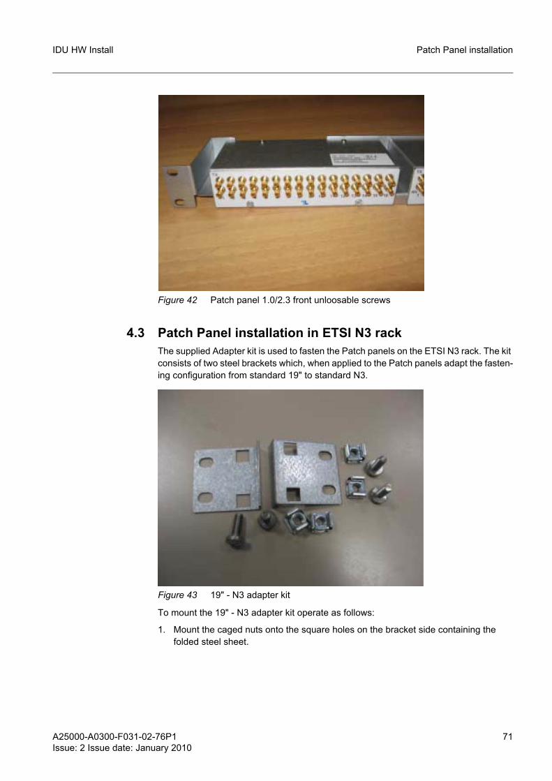
A25000-A0300-F031-02-76P1Issue: 2 Issue date: January 2010
71
IDU HW Install Patch Panel installation
Figure 42 Patch panel 1.0/2.3 front unloosable screws
4.3 Patch Panel installation in ETSI N3 rackThe supplied Adapter kit is used to fasten the Patch panels on the ETSI N3 rack. The kit consists of two steel brackets which, when applied to the Patch panels adapt the fasten-ing configuration from standard 19" to standard N3.
Figure 43 19" - N3 adapter kit
To mount the 19" - N3 adapter kit operate as follows:
1. Mount the caged nuts onto the square holes on the bracket side containing the folded steel sheet.
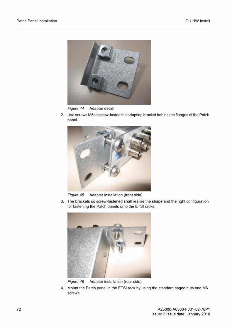
72 A25000-A0300-F031-02-76P1Issue: 2 Issue date: January 2010
IDU HW InstallPatch Panel installation
Figure 44 Adapter detail2. Use screws M6 to screw-fasten the adapting bracket behind the flanges of the Patch
panel.
Figure 45 Adapter installation (front side)3. The brackets so screw-fastened shall realise the shape and the right configuration
for fastening the Patch panels onto the ETSI racks.
Figure 46 Adapter installation (rear side)4. Mount the Patch panel in the ETSI rack by using the standard caged nuts and M6
screws.
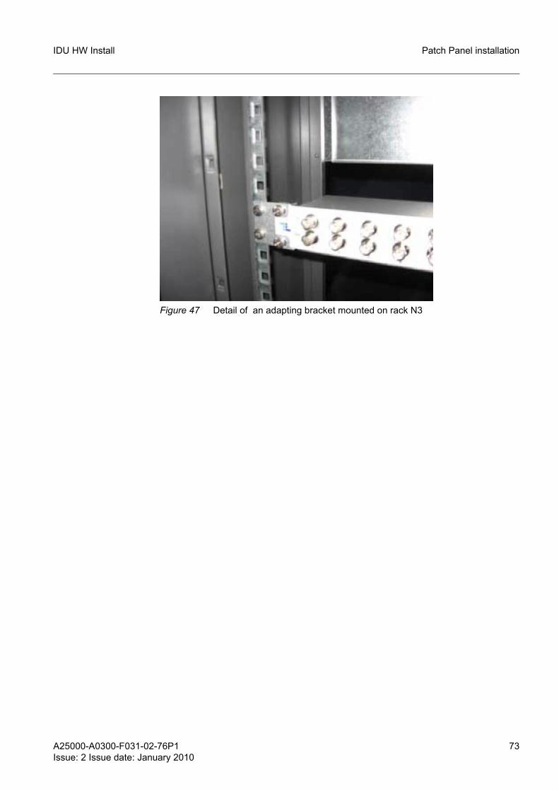
A25000-A0300-F031-02-76P1Issue: 2 Issue date: January 2010
73
IDU HW Install Patch Panel installation
Figure 47 Detail of an adapting bracket mounted on rack N3
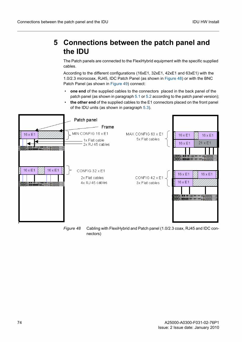
74 A25000-A0300-F031-02-76P1Issue: 2 Issue date: January 2010
IDU HW InstallConnections between the patch panel and the IDU
5 Connections between the patch panel and the IDUThe Patch panels are connected to the FlexiHybrid equipment with the specific supplied cables.
According to the different configurations (16xE1, 32xE1, 42xE1 and 63xE1) with the 1.0/2.3 microcoax, RJ45, IDC Patch Panel (as shown in Figure 48) or with the BNC Patch Panel (as shown in Figure 49) connect:
• one end of the supplied cables to the connectors placed in the back panel of the patch panel (as shown in paragraph 5.1 or 5.2 according to the patch panel version);
• the other end of the supplied cables to the E1 connectors placed on the front panel of the IDU units (as shown in paragraph 5.3).
Figure 48 Cabling with FlexiHybrid and Patch panel (1.0/2.3 coax, RJ45 and IDC con-nectors)
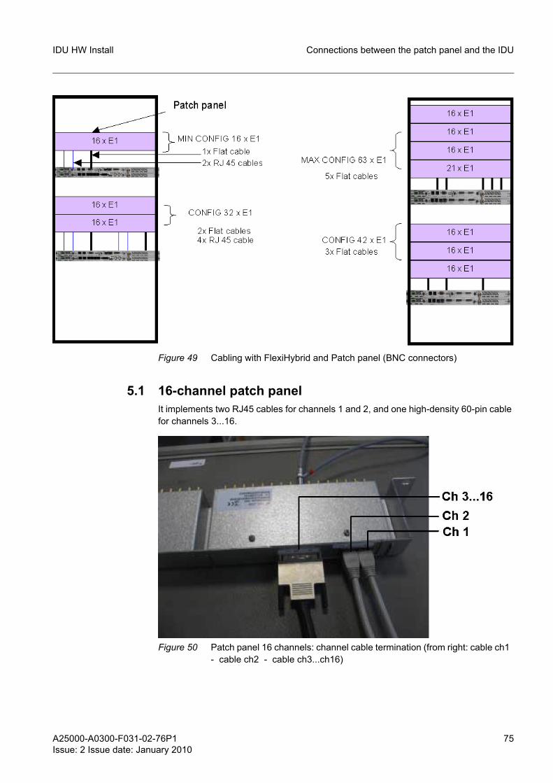
A25000-A0300-F031-02-76P1Issue: 2 Issue date: January 2010
75
IDU HW Install Connections between the patch panel and the IDU
Figure 49 Cabling with FlexiHybrid and Patch panel (BNC connectors)
5.1 16-channel patch panelIt implements two RJ45 cables for channels 1 and 2, and one high-density 60-pin cable for channels 3...16.
Figure 50 Patch panel 16 channels: channel cable termination (from right: cable ch1 - cable ch2 - cable ch3...ch16)
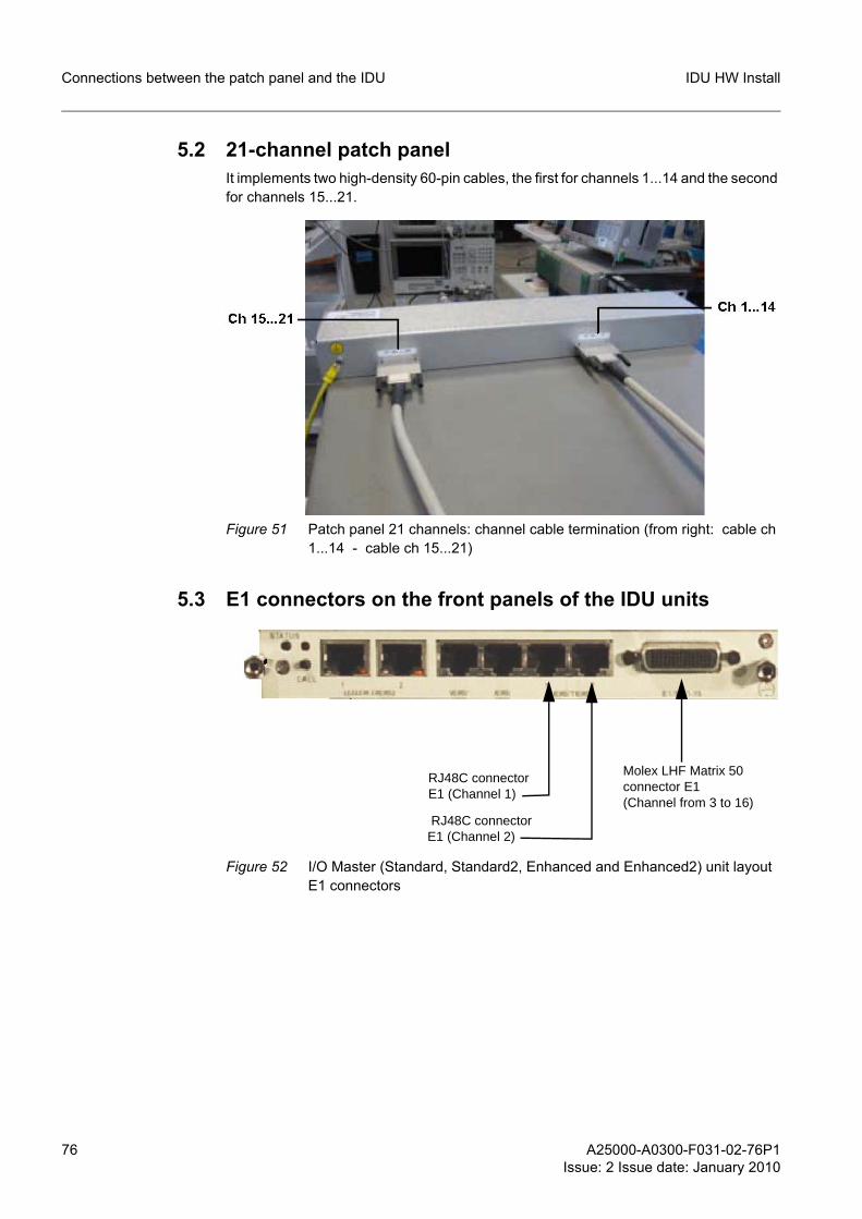
76 A25000-A0300-F031-02-76P1Issue: 2 Issue date: January 2010
IDU HW InstallConnections between the patch panel and the IDU
5.2 21-channel patch panelIt implements two high-density 60-pin cables, the first for channels 1...14 and the second for channels 15...21.
Figure 51 Patch panel 21 channels: channel cable termination (from right: cable ch 1...14 - cable ch 15...21)
5.3 E1 connectors on the front panels of the IDU units
Figure 52 I/O Master (Standard, Standard2, Enhanced and Enhanced2) unit layout E1 connectors
Molex LHF Matrix 50connector E1(Channel from 3 to 16)
RJ48C connectorE1 (Channel 1)
RJ48C connectorE1 (Channel 2)
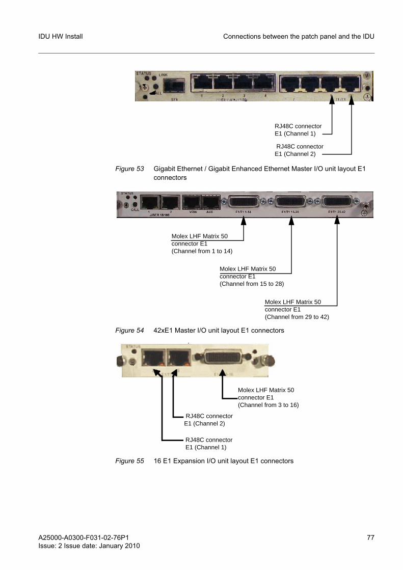
A25000-A0300-F031-02-76P1Issue: 2 Issue date: January 2010
77
IDU HW Install Connections between the patch panel and the IDU
Figure 53 Gigabit Ethernet / Gigabit Enhanced Ethernet Master I/O unit layout E1 connectors
Figure 54 42xE1 Master I/O unit layout E1 connectors
Figure 55 16 E1 Expansion I/O unit layout E1 connectors
RJ48C connectorE1 (Channel 1)
RJ48C connectorE1 (Channel 2)
Molex LHF Matrix 50connector E1(Channel from 1 to 14)
Molex LHF Matrix 50connector E1(Channel from 15 to 28)
Molex LHF Matrix 50connector E1(Channel from 29 to 42)
Molex LHF Matrix 50connector E1(Channel from 3 to 16)
RJ48C connectorE1 (Channel 1)
RJ48C connectorE1 (Channel 2)
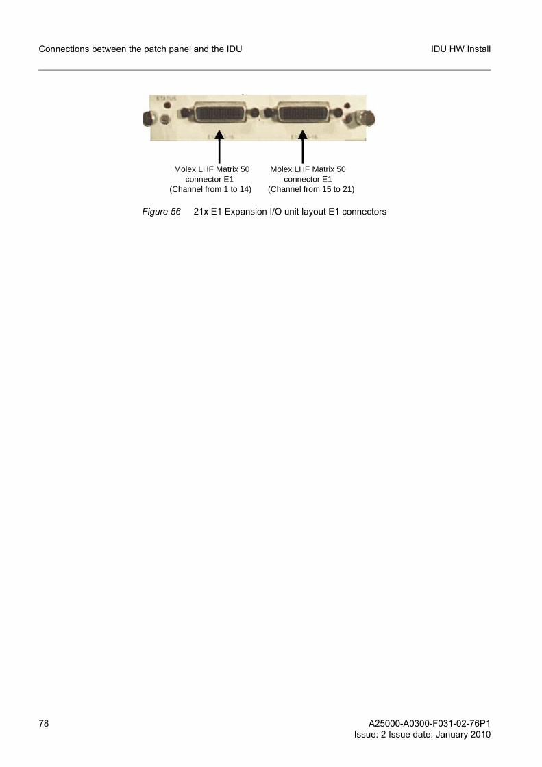
78 A25000-A0300-F031-02-76P1Issue: 2 Issue date: January 2010
IDU HW InstallConnections between the patch panel and the IDU
Figure 56 21x E1 Expansion I/O unit layout E1 connectors
Molex LHF Matrix 50connector E1
(Channel from 15 to 21)
Molex LHF Matrix 50connector E1
(Channel from 1 to 14)
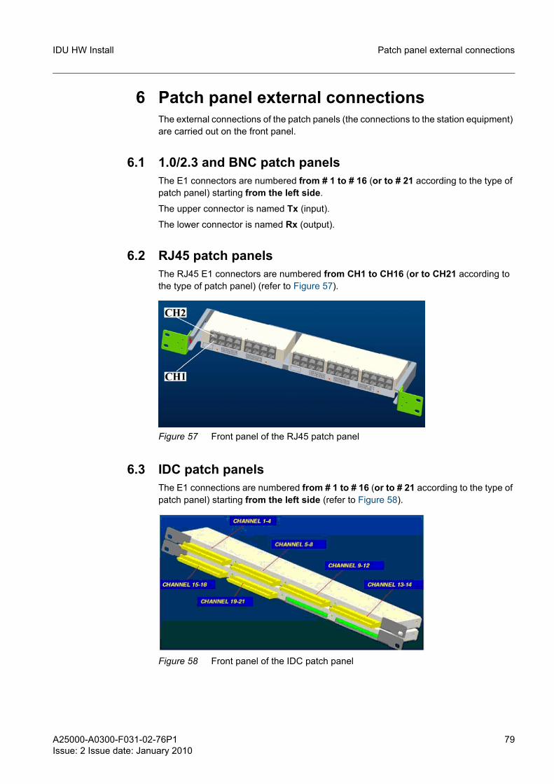
A25000-A0300-F031-02-76P1Issue: 2 Issue date: January 2010
79
IDU HW Install Patch panel external connections
6 Patch panel external connectionsThe external connections of the patch panels (the connections to the station equipment) are carried out on the front panel.
6.1 1.0/2.3 and BNC patch panelsThe E1 connectors are numbered from # 1 to # 16 (or to # 21 according to the type of patch panel) starting from the left side.
The upper connector is named Tx (input).
The lower connector is named Rx (output).
6.2 RJ45 patch panelsThe RJ45 E1 connectors are numbered from CH1 to CH16 (or to CH21 according to the type of patch panel) (refer to Figure 57).
Figure 57 Front panel of the RJ45 patch panel
6.3 IDC patch panelsThe E1 connections are numbered from # 1 to # 16 (or to # 21 according to the type of patch panel) starting from the left side (refer to Figure 58).
Figure 58 Front panel of the IDC patch panel
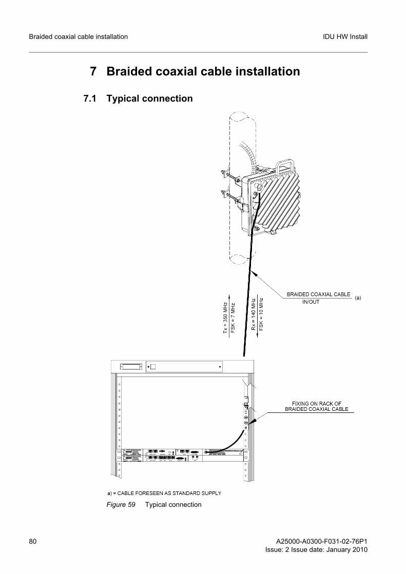
80 A25000-A0300-F031-02-76P1Issue: 2 Issue date: January 2010
IDU HW InstallBraided coaxial cable installation
7 Braided coaxial cable installation
7.1 Typical connection
Figure 59 Typical connection
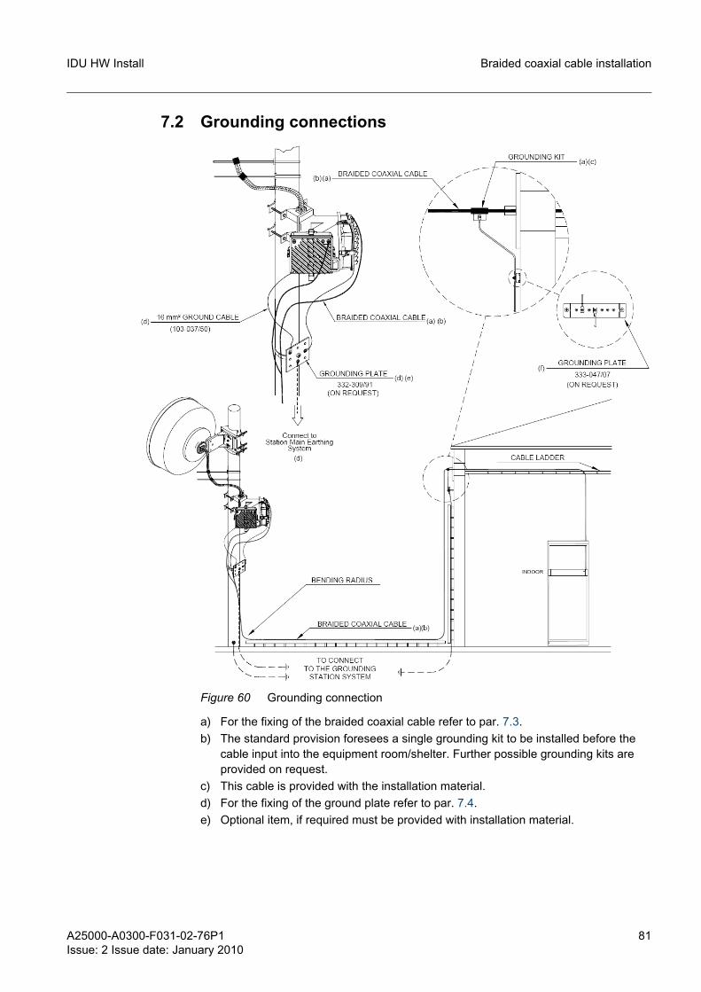
A25000-A0300-F031-02-76P1Issue: 2 Issue date: January 2010
81
IDU HW Install Braided coaxial cable installation
7.2 Grounding connections
Figure 60 Grounding connection
a) For the fixing of the braided coaxial cable refer to par. 7.3.b) The standard provision foresees a single grounding kit to be installed before the
cable input into the equipment room/shelter. Further possible grounding kits are provided on request.
c) This cable is provided with the installation material.d) For the fixing of the ground plate refer to par. 7.4.e) Optional item, if required must be provided with installation material.
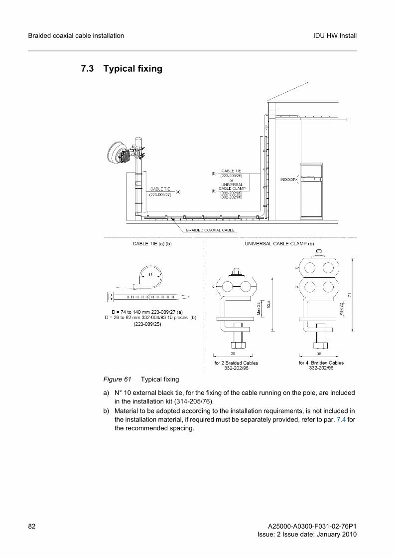
82 A25000-A0300-F031-02-76P1Issue: 2 Issue date: January 2010
IDU HW InstallBraided coaxial cable installation
7.3 Typical fixing
Figure 61 Typical fixing
a) N° 10 external black tie, for the fixing of the cable running on the pole, are included in the installation kit (314-205/76).
b) Material to be adopted according to the installation requirements, is not included in the installation material, if required must be separately provided, refer to par. 7.4 for the recommended spacing.
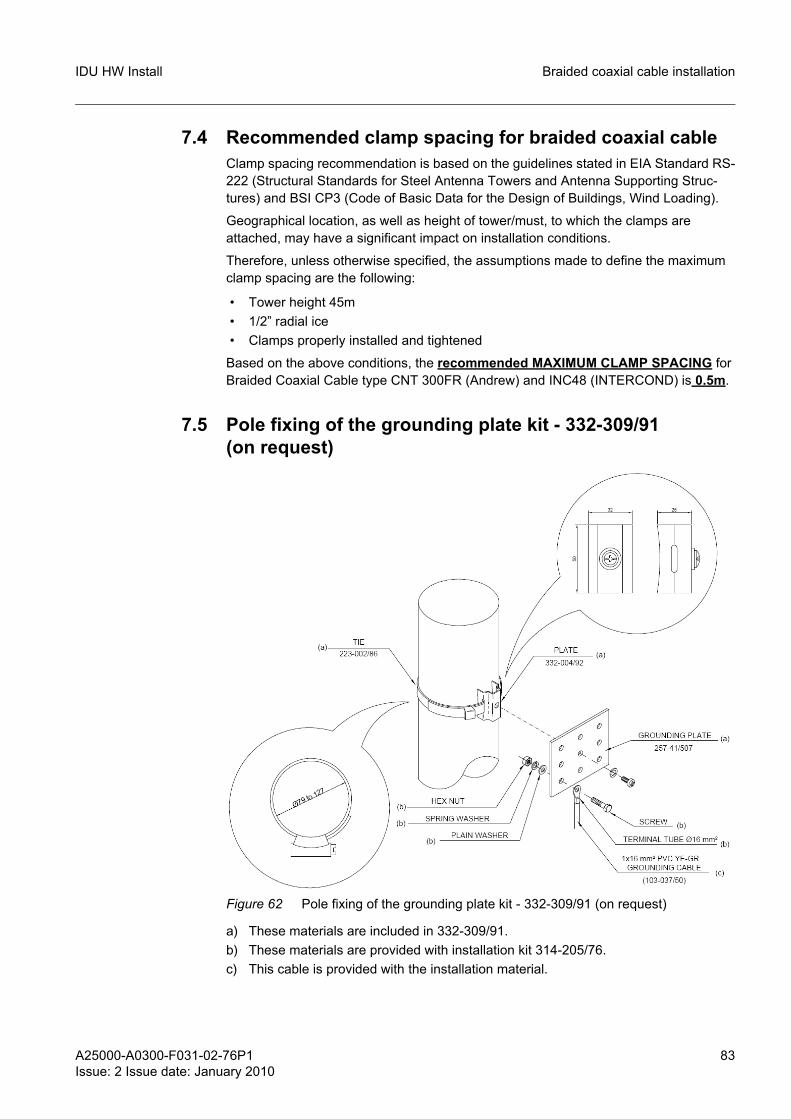
A25000-A0300-F031-02-76P1Issue: 2 Issue date: January 2010
83
IDU HW Install Braided coaxial cable installation
7.4 Recommended clamp spacing for braided coaxial cableClamp spacing recommendation is based on the guidelines stated in EIA Standard RS-222 (Structural Standards for Steel Antenna Towers and Antenna Supporting Struc-tures) and BSI CP3 (Code of Basic Data for the Design of Buildings, Wind Loading).
Geographical location, as well as height of tower/must, to which the clamps are attached, may have a significant impact on installation conditions.
Therefore, unless otherwise specified, the assumptions made to define the maximum clamp spacing are the following:
• Tower height 45m • 1/2” radial ice • Clamps properly installed and tightened
Based on the above conditions, the recommended MAXIMUM CLAMP SPACING for Braided Coaxial Cable type CNT 300FR (Andrew) and INC48 (INTERCOND) is 0.5m.
7.5 Pole fixing of the grounding plate kit - 332-309/91 (on request)
Figure 62 Pole fixing of the grounding plate kit - 332-309/91 (on request)
a) These materials are included in 332-309/91.b) These materials are provided with installation kit 314-205/76.c) This cable is provided with the installation material.
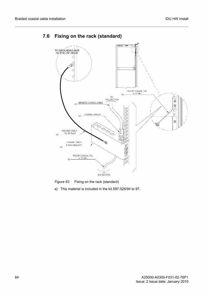
84 A25000-A0300-F031-02-76P1Issue: 2 Issue date: January 2010
IDU HW InstallBraided coaxial cable installation
7.6 Fixing on the rack (standard)
Figure 63 Fixing on the rack (standard)
a) This material is included in the kit 597-526/94 to 97.
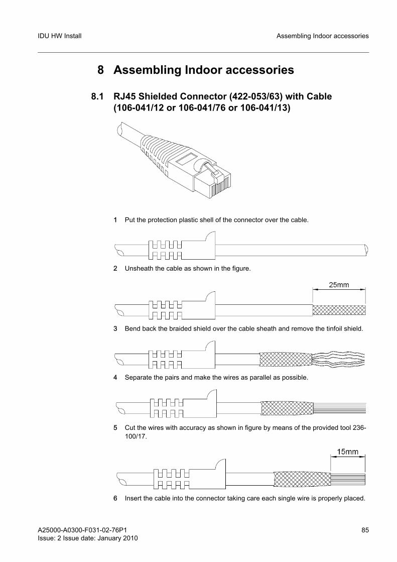
A25000-A0300-F031-02-76P1Issue: 2 Issue date: January 2010
85
IDU HW Install Assembling Indoor accessories
8 Assembling Indoor accessories
8.1 RJ45 Shielded Connector (422-053/63) with Cable (106-041/12 or 106-041/76 or 106-041/13)
1 Put the protection plastic shell of the connector over the cable.
2 Unsheath the cable as shown in the figure.
3 Bend back the braided shield over the cable sheath and remove the tinfoil shield.
4 Separate the pairs and make the wires as parallel as possible.
5 Cut the wires with accuracy as shown in figure by means of the provided tool 236-100/17.
6 Insert the cable into the connector taking care each single wire is properly placed.
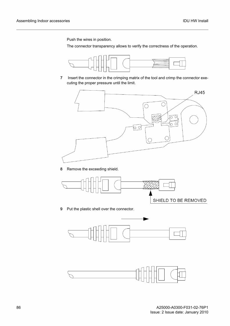
86 A25000-A0300-F031-02-76P1Issue: 2 Issue date: January 2010
IDU HW InstallAssembling Indoor accessories
Push the wires in position.
The connector transparency allows to verify the correctness of the operation.
7 Insert the connector in the crimping matrix of the tool and crimp the connector exe-cuting the proper pressure until the limit.
8 Remove the exceeding shield.
9 Put the plastic shell over the connector.
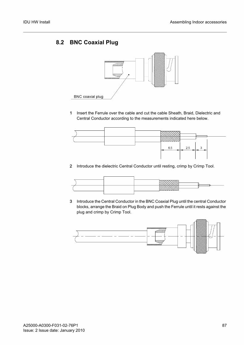
A25000-A0300-F031-02-76P1Issue: 2 Issue date: January 2010
87
IDU HW Install Assembling Indoor accessories
8.2 BNC Coaxial Plug
1 Insert the Ferrule over the cable and cut the cable Sheath, Braid, Dielectric and Central Conductor according to the measurements indicated here below.
2 Introduce the dielectric Central Conductor until resting, crimp by Crimp Tool.
3 Introduce the Central Conductor in the BNC Coaxial Plug until the central Conductor blocks, arrange the Braid on Plug Body and push the Ferrule until it rests against the plug and crimp by Crimp Tool.
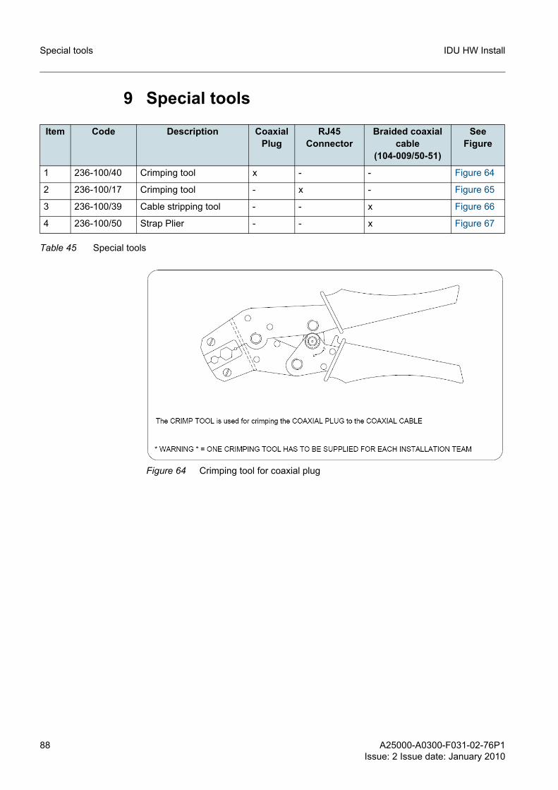
88 A25000-A0300-F031-02-76P1Issue: 2 Issue date: January 2010
IDU HW InstallSpecial tools
9 Special tools
Figure 64 Crimping tool for coaxial plug
Item Code Description CoaxialPlug
RJ45 Connector
Braided coaxial cable
(104-009/50-51)
SeeFigure
1 236-100/40 Crimping tool x - - Figure 64
2 236-100/17 Crimping tool - x - Figure 65
3 236-100/39 Cable stripping tool - - x Figure 66
4 236-100/50 Strap Plier - - x Figure 67
Table 45 Special tools
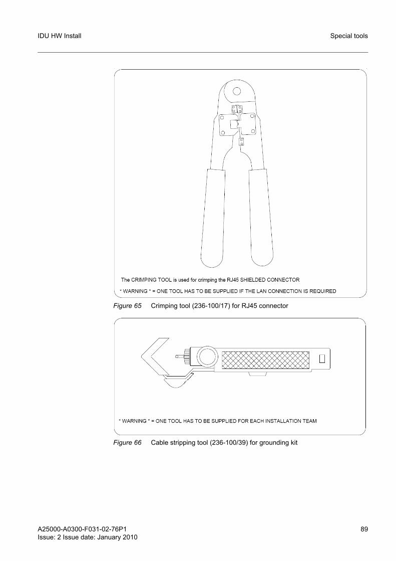
A25000-A0300-F031-02-76P1Issue: 2 Issue date: January 2010
89
IDU HW Install Special tools
Figure 65 Crimping tool (236-100/17) for RJ45 connector
Figure 66 Cable stripping tool (236-100/39) for grounding kit
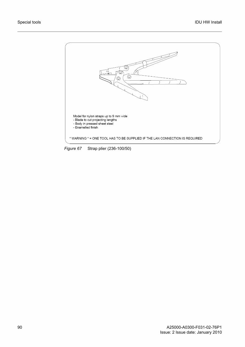
90 A25000-A0300-F031-02-76P1Issue: 2 Issue date: January 2010
IDU HW InstallSpecial tools
Figure 67 Strap plier (236-100/50)
Top Related