


Languages
Pages
Legal


HYPERLOOP ACCELERATOR
By
Michael Eraci
Mohammad Jaber
Shivam Sharma
Final Report for ECE 445, Senior Design, Spring 2015
TA: Benjamin Cahill
7th may 2015
Project No. 24

ii
Abstract
The hyper loop is a conceptual super-fast fifth mode of transportation, the designs for which have been
put forth by Elon musk, the CEO of Tesla Motors & SpaceX. The designs have been made public for
anyone to view and improve upon as musk hopes this to be an open-source project. The main concept
of hyper loop involves the movement of an aerodynamic capsule through partial vacuum tubes
Since, Spring 2013, the Department of Mechanical Engineering at the University of Illinois, has been
working to create a proof of concept prototype of the hyper loop. The prototype consists of a loop of
partial vacuum tubing and aims to launch a small capsule around it. The goal of our project is to build a
linear accelerator in the form a multi-stage coil gun in order to impart enough momentum to a capsule
to move around the loop continuously without reset
iii
Contents
1. Introduction .............................................................................................................................................. 1
1.1 Block Diagram
2 Design ......................................................................................................................................................... 2
2.1 General Description ............................................................................................................................ 2
2.2 Power & Control Circuitry……………………………………………………………………………………………………………..2
2.2.1 Power Circuitry
2.2.2 Control Circuitry
2.3 Electromagnetic Theory & Coil Design…………………………………………………………………………………………...4
2.3.1 Introduction
2.3.2 Equations
2.3.3 Important Parameters
2.3.4 Determining Optimal Capsule Length
3. Design Verification .................................................................................................................................... 9
3.1 Circuit Functionality ............................................................................................................................ 9
3.1.1 Capsile KineticsError! Bookmark not defined.
3.1.2 Sensitivity of sensors
3.1.3 Power Source
3.1.4 Thyristor Activation
3.2 Testing to verify optimal capsule length………………………………………………………………………………………9
3.3 Inductance testing……………………………………………………………………………………………………………………....10
4. Costs ........................................................................................................................................................ 11
4.1 Parts .................................................................................................................................................. 11
4.2 Labor ................................................................................................................................................. 12
5. Conclusion ............................................................................................................................................... 13
iv
5.1 Accomplishments .............................................................................................................................. 13
5.2 Future work ....................................................................................................................................... 13
References .................................................................................................................................................. 14
Appendix A Requirement and Verification Table ................................................................................... 15
Appendix B Arduino Code………………………………………………………………………………………………………………….16
1
1. Introduction
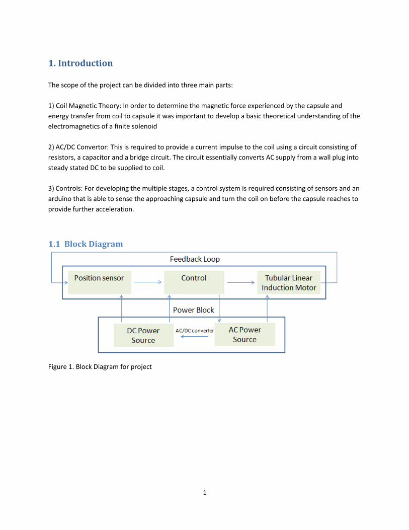
The scope of the project can be divided into three main parts:
1) Coil Magnetic Theory: In order to determine the magnetic force experienced by the capsule and
energy transfer from coil to capsule it was important to develop a basic theoretical understanding of the
electromagnetics of a finite solenoid
2) AC/DC Convertor: This is required to provide a current impulse to the coil using a circuit consisting of
resistors, a capacitor and a bridge circuit. The circuit essentially converts AC supply from a wall plug into
steady stated DC to be supplied to coil.
3) Controls: For developing the multiple stages, a control system is required consisting of sensors and an
arduino that is able to sense the approaching capsule and turn the coil on before the capsule reaches to
provide further acceleration.
1.1 Block Diagram
Figure 1. Block Diagram for project
2
2 Design
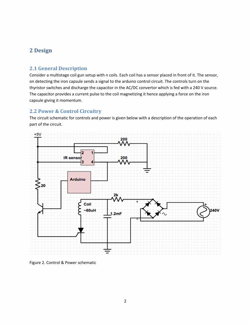
2.1 General Description Consider a multistage coil gun setup with n coils. Each coil has a sensor placed in front of it. The sensor,
on detecting the iron capsule sends a signal to the arduino control circuit. The controls turn on the
thyristor switches and discharge the capacitor in the AC/DC convertor which is fed with a 240 V source.
The capacitor provides a current pulse to the coil magnetizing it hence applying a force on the iron
capsule giving it momentum.
2.2 Power & Control Circuitry The circuit schematic for controls and power is given below with a description of the operation of each
part of the circuit.
Figure 2. Control & Power schematic
3
2.2.1 Power Circuitry The premise of our charging circuit is that 240 VRMS needs to be converted into 260 VDC in
order to charge a Capacitor. Once the capacitor is charged, one can use the control circuit to
discharge the capacitor through the coil to generate a pulse.
A 240 VRMS wall power input goes through a bridge rectifier that takes the absolute value of
the input voltage. The output of the rectifier goes through a 2kΩ 50W power resistor to the 1.2
µF capacitor to charge the capacitor when the bridge rectifier voltage is higher than the
capacitor voltage, and slowly discharge the capacitor for the brief period when the bridge
rectifier voltage is lower than the capacitor voltage.
While this method for charging a capacitor is crude, our requirements for the coil only need the
capacitor voltage to reach 260V within 10 seconds. For designing purposes we will engineer 4
time constants within 10 seconds to allow for recharging. We chose to use a 2kΩ resistor with
the 1.2 µF capacitor that created a time constant of 2.4 seconds. Thus we estimated it would
take 9.6 seconds to charge the capacitor (it actually took 8 seconds).
2.2.2 Control Circuitry An Arduino Uno is used to measure the intensity of the input from an IR sensor. The Arduino is
necessary because each sensor has different sensitivities to reflected IR light. That causes the
threshold signal to differ for each sensor and requires us to use the Arduino to calibrate the
output of each sensor for use in our design.
Once the sensors tell the Arduino to fire a coil, the Arduino provides a small base current to an
NPN common emitter circuit. The common emitter circuit amplifies the Arduino signal and
provides at least 100mA to a thyristor in order to activate the firing of the coil. Without the
thyristor the Arduino would burn out since it can only provide up to 40 mA.
One last note on the control circuit is that we used a 9V battery as a supply to the Arduino, the sensors,
and the thyristor base current. For future work we will use a down-transformer to build the 9V source
into the circuit.
4
2.3 Electromagnetic Theory & Coil Design
2.3.1 Introduction The basic electromagnetic theory involved in the operation of a coil gun is as follows.
Consider a circular coil of winding with “N” turns. When we pass a current (“I”) through the coil,
given ampere’s law, magnetic flux (“ϕ”) is established in the area encompassed by the coil. This
magnetic field is strongest at the center of the coil and decreases axially. The coil is now
essentially a temporary magnet with the north pole at the face through which magnetic flux
lines come out and the other face the south pole.
A ferromagnetic material in the vicinity of the coil (temporary magnet) will get magnetized. The
surface of the material facing a particular pole of the coil is magnetized as an opposite pole.
Magnetic dipoles within the ferromagnetic material will align themselves so that the material is
attracted to the magnetic field. In this way the ferromagnetic cylinder will experience an
attractive force due to the magnetic field and get accelerated towards the coil. In a multi-stage
coil, coils are placed next to each other and once the cylinder has passed completely through
one coil, the current through it is turned off (if the current remained on then once the
ferromagnetic material was on the other side it would experience attractive force in the
direction it just came from) and the current in the coil next to it is turned on. This way the
ferromagnetic material continues to experience attractive forces in the same direction and can
be linearly accelerated.
2.3.2 Equation for Magnetic Field Intensity and Force for a single coil The first step towards building the coil gun required us to establish a model to study the
magnetic field produced by the coil and the magnetic force experienced by the capsule. After
consulting with the mechanical engineering team it was decided that a linear model for
magnetic field obtained from a research paper [1] would be used. The linear model is described
below
This section uses a linear model to approximate the magnetic field intensity (H) and magnetic
force (F) at a point ‘p’, some distance x from the coil with N turns. H and F are then plotted as a
function of distance.
5
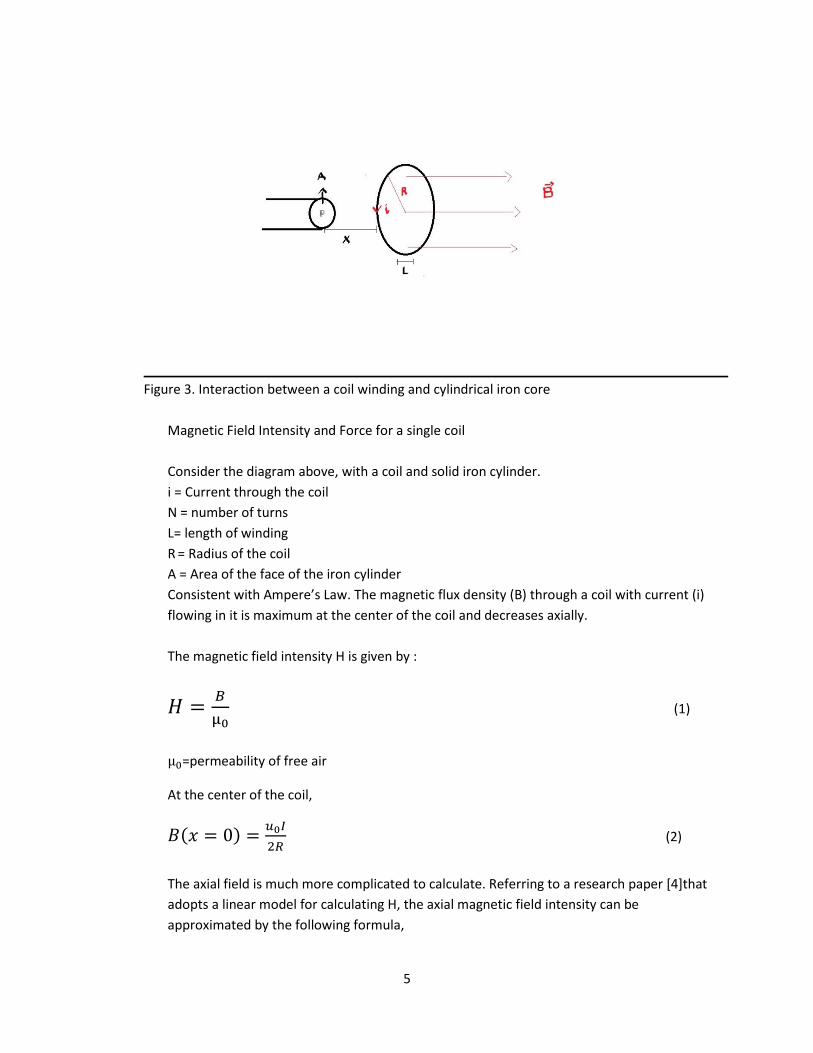
Figure 3. Interaction between a coil winding and cylindrical iron core
Magnetic Field Intensity and Force for a single coil
Consider the diagram above, with a coil and solid iron cylinder.
i = Current through the coil
N = number of turns
L= length of winding
R = Radius of the coil
A = Area of the face of the iron cylinder
Consistent with Ampere’s Law. The magnetic flux density (B) through a coil with current (i)
flowing in it is maximum at the center of the coil and decreases axially.
The magnetic field intensity H is given by :
𝐻 =𝐵
µ0 (1)
µ0=permeability of free air
At the center of the coil,
𝐵(𝑥 = 0) =𝑢0𝐼
2𝑅 (2)
The axial field is much more complicated to calculate. Referring to a research paper [4]that
adopts a linear model for calculating H, the axial magnetic field intensity can be
approximated by the following formula,
6
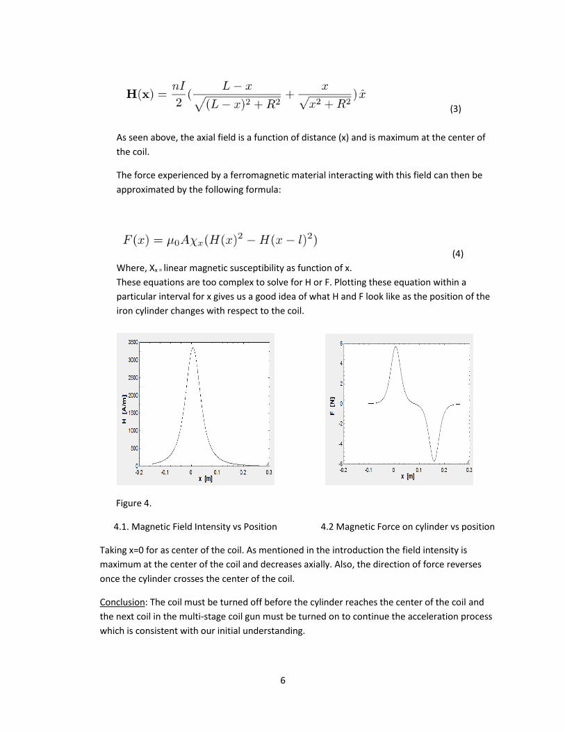
(3)
As seen above, the axial field is a function of distance (x) and is maximum at the center of
the coil.
The force experienced by a ferromagnetic material interacting with this field can then be
approximated by the following formula:
(4)
Where, Χx = linear magnetic susceptibility as function of x.
These equations are too complex to solve for H or F. Plotting these equation within a
particular interval for x gives us a good idea of what H and F look like as the position of the
iron cylinder changes with respect to the coil.
Figure 4.
4.1. Magnetic Field Intensity vs Position 4.2 Magnetic Force on cylinder vs position
Taking x=0 for as center of the coil. As mentioned in the introduction the field intensity is
maximum at the center of the coil and decreases axially. Also, the direction of force reverses
once the cylinder crosses the center of the coil.
Conclusion: The coil must be turned off before the cylinder reaches the center of the coil and
the next coil in the multi-stage coil gun must be turned on to continue the acceleration process
which is consistent with our initial understanding.
7
2.3.3 Important coil parameters The following are the parameters of the coil gun system that crucially define its function:
Coil Radius: “R” ( this is the radius of the coil + the thickness of the PVC pipe (hyperloop tubing)
it is wrapped around)
Coil Length: “c”
Coil # Turns: “N”
Coil Inductance: “L”
Capsule Radius: “r”
Capsule Length: “l”
Capsule Material Permeability: “µ”
Minimum distance the capsule must be placed from the center of the coil to experience
maximum force: “x”
Distance between coils for the multi-stage: “y”
Since we took over the project from a previous team, certain parameters of the coil gun were fixed from
the beginning and we had to work within those constraints:
R=4.125cm
N=300
c=1.3 cm
r=2.475cm (because the hyperloop concept requires that the radius of the capsule be 60% of the radius
of the tubing)
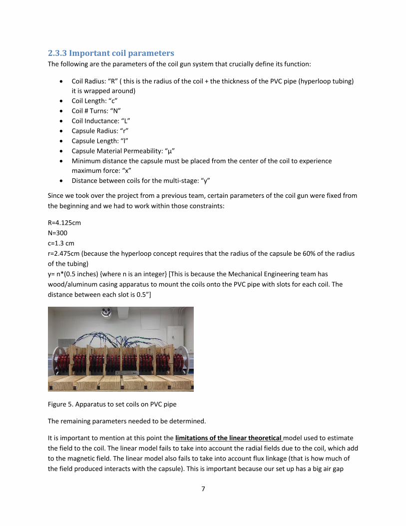
y= n*(0.5 inches) where n is an integer [This is because the Mechanical Engineering team has
wood/aluminum casing apparatus to mount the coils onto the PVC pipe with slots for each coil. The
distance between each slot is 0.5”]
Figure 5. Apparatus to set coils on PVC pipe
The remaining parameters needed to be determined.
It is important to mention at this point the limitations of the linear theoretical model used to estimate
the field to the coil. The linear model fails to take into account the radial fields due to the coil, which add
to the magnetic field. The linear model also fails to take into account flux linkage (that is how much of
the field produced interacts with the capsule). This is important because our set up has a big air gap
8
between the coil and the capsule. Thus, there isn’t 100% energy transfer from the coil to capsule. It is
important to know how much energy is lost in the air gap to truly determine the force and velocity
gained by the capsule. Since flux linkage is associated with the dimensions of the iron capsule, the first
step was to estimate an ideal length “l” for the capsule. In order to determine optimal “l”, we first tried
to manipulate the Force Equation (4). However, the results obtained were unsatisfactory. This, I believe,
was due to the limitation of the linear theoretical model mentioned above. At that point, ww decided to
try to solve the problem empirically through testing. In order to determine the optimal length, we
decided to manipulate the relationship between the inductance of coil and its parameters.
2.3.4 Determining optimal length of capsule In order to determine optimal length, first we need to look at the relationship among the current
through the coil (I) , the flux through the coil (φ) and the inductance of the coil (L), given by
φ = L/I (9)
Now, consider a coil with an air core. Its inductance is given by :
𝐿𝑎𝑖𝑟 = 𝑢0𝑁2𝐴/𝑐 (10)
Now consider an iron core with area of cross-section and length same as that of the coil. Its Inductance
is given by
𝐿𝑖𝑟𝑜𝑛 =𝑢𝑚𝑁2𝐴
𝑙 (11)
Where, um is the permeability of the iron core.
From (10), it is evident that the inductance of the coil is inversely proportional to its length. From (9), we
see that the flux through the coil is proportional to L for a fixed I. I is determined by our bridge circuit
and is fixed. From (11), we also see that the inductance of a coil with an iron core inside it, is maximum
when the iron completely occupies the volume inside the coil. Thus, the flux through the coil will also be
maximum for that case. Hence, the force experienced by the capsule will also be maximum. It is safe to
assume at this point the optimal length of the capsule should be equal to that of the coil. Further
evidence is provided for this when we consider reluctance of an iron core. Reluctance (R ) in magnetic
circuits is akin to resistance in electrical circuits. The Reluctance of an iron core is defined as its
opposition to establish flux in the core as is given by
𝑅 =𝑙
µ𝑚∗𝐴 (12)
Hence, in order to have maximum flux through the core its length should be as small as possible. Thus,
l=c is a good estimate to take. Since, the radius of the core is fixed, smallest possible l will also minimize
its weight and hence air friction during its motion.
Further, tests were conducted to affirm this approximation and are described in the verifications
section.
9
3. Design Verification The parts to verify fall into two categories: circuit functionality, and desired physical properties.
3.1 Circuit Functionality
3.1.1 Capsule Kinetics
To ensure the motor can sufficiently accelerate the capsule, we placed a barrier 20cm downstream from
the coils. When fired, the capsule was able to consistently hit the barrier. In addition, we were able to
engineer the system to not need a reset button, which is a requirement for automatically re-firing. We
passed two capsules through the coil and both were accelerated to hit the barrier.
3.1.2 Sensitivity of Sensors
Each IR sensor was unique in that some we more sensitive to reflected light than others. While all
sensors provided a baseline voltage of 0.8V-1V, when the capsule passed over the sensor the voltage
would go from 1.2V-3V. As such we set a threshold voltage of 1.1V to fire the capsule. We also
programmed an LED light to turn on whenever a sensor detected the capsule. We used this LED for
demonstration purposes and it operated as expected.
3.1.3 Power Source
When fired, the capacitors used to generate the pulse need to recharge faster than the time it would
take for the capsule to make it around the loop. We estimated this time would be 10 seconds. While we
designed the recharging to be finished in 9.6 seconds, we were pleasantly surprised when it only took 8
seconds to recharge to 210 VDC. We used an iPhone as a timer and a voltmeter to measure the DC
voltage.
3.1.4 Thyristor Activation
To ensure that the Thyristors turns on to activate the coil current we needed to supply at least 100mA to
the base of the Thyristor. Because we are using a common emitter setup, we can measure the current
through the 20 Ω resistor as a measure of the thyristor base current. When the Arduino output to the
common emitter base was 5V the 20 Ω resistor current was 166 mA which is more than enough to turn
on the thyristor. When attached to the coil, the thyristor consistently fired the coil as expected.
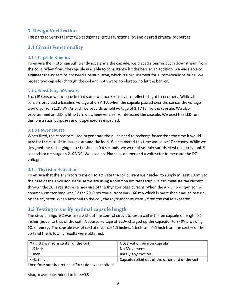
3.2 Testing to verify optimal capsule length The circuit in figure 2 was used without the control circuit to test a coil with iron capsule of length 0.5
inches (equal to that of the coil). A source voltage of 220V charged up the capacitor to 340V providing
60J of energy.The capsule was placed at distance 1.5 inches, 1 inch and 0.5 inch from the center of the
coil and the following results were obtained:
X ( distance from center of the coil) Observation on iron capsule
1.5 inch No Movement
1 inch Barely any motion
<=0.5 inch Capsule rolled out of the other end of the coil
Therefore our theoretical affirmation was realized.
Also, x was determined to be <=0.5
10
3.3 Test to determine coil inductance The relationship between a coil’s inductance and its parameters is as described below:
𝐿 = 𝑢0𝑁2𝐴/𝑐 (5)
Where u0 = permeability of free air
A = area of cross-section of the coil.
The theoretical value of inductance was found to be L= 6.053 mH. It was important that this value was
verified through experimental testing.
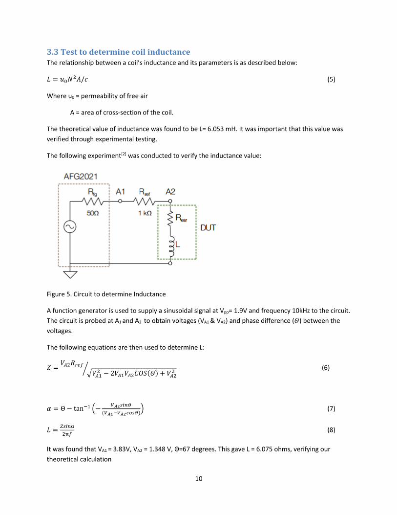
The following experiment[2] was conducted to verify the inductance value:
Figure 5. Circuit to determine Inductance
A function generator is used to supply a sinusoidal signal at Vpp= 1.9V and frequency 10kHz to the circuit.
The circuit is probed at A1 and A2 to obtain voltages (VA1 & VA2) and phase difference (𝛩) between the
voltages.
The following equations are then used to determine L:
𝑍 =𝑉𝐴2𝑅𝑟𝑒𝑓
√𝑉𝐴12 − 2𝑉𝐴1𝑉𝐴2𝐶𝑂𝑆(𝛩) + 𝑉𝐴2
2⁄ (6)
𝛼 = Θ − tan−1 (−𝑉𝐴2𝑠𝑖𝑛𝛩
(𝑉𝐴1−𝑉𝐴2𝑐𝑜𝑠𝛩)) (7)
𝐿 =𝑍𝑠𝑖𝑛α
2π𝑓 (8)
It was found that VA1 = 3.83V, VA2 = 1.348 V, Θ=67 degrees. This gave L = 6.075 ohms, verifying our
theoretical calculation
11
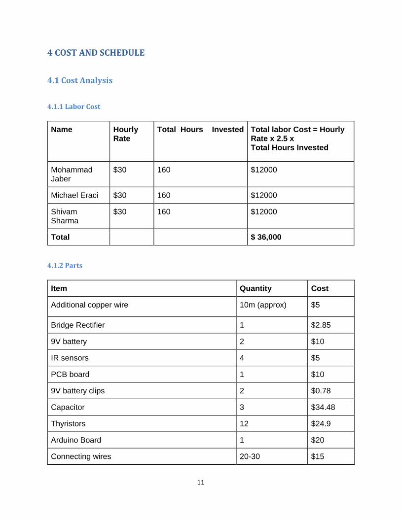
4 COST AND SCHEDULE
4.1 Cost Analysis
4.1.1 Labor Cost
Name Hourly Rate
Total Hours Invested Total labor Cost = Hourly Rate x 2.5 x
Total Hours Invested
Mohammad Jaber
$30 160 $12000
Michael Eraci $30 160 $12000
Shivam Sharma
$30 160 $12000
Total
$ 36,000
4.1.2 Parts
Item Quantity Cost
Additional copper wire 10m (approx) $5
Bridge Rectifier 1 $2.85
9V battery 2 $10
IR sensors 4 $5
PCB board 1 $10
9V battery clips 2 $0.78
Capacitor 3 $34.48
Thyristors 12 $24.9
Arduino Board 1 $20
Connecting wires 20-30 $15
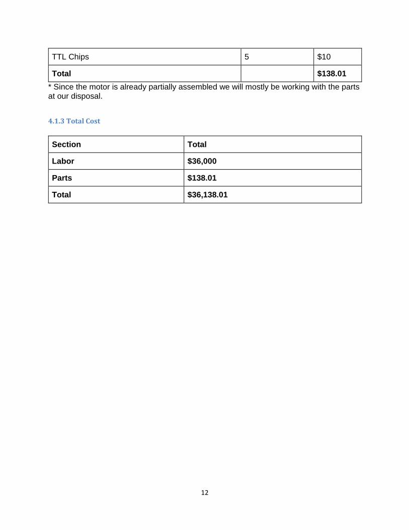
12
TTL Chips 5 $10
Total
$138.01
* Since the motor is already partially assembled we will mostly be working with the parts at our disposal.
4.1.3 Total Cost
Section Total
Labor $36,000
Parts $138.01
Total $36,138.01
13
5. Conclusion
5.1 Accomplishments We successfully demoed a two stage coil gun. The two coils imparted momentum to a two inch piece of
iron and move it approximately 0.2m. The sensor and controls allowed for continuous operation of coil
gun without having to reset the 240V source.
5.2 Uncertainties The logic component of our circuit is powered through a 9V lithium battery. Since, these batteries have
limited life, they will need to be replaced at some point in the future.
5.3 Future work Future work involves building the control and AC to DC convertor circuits for 18 coils, in order to get the
capsule to navigate the entire loop of tubing.
Work also needs to be done to impart power to the control circuit through the 240V source instead of
the 9V battery.

14
References
[1] Jeff Holzgrafe, Nathan Lintz, Nick Eyre, & Jay Patterson, Effect of Projectile Design on Coil Gun
Performance ,Franklin W. Olin College of Engineering, December 14, 2012;
http://www.nickeyre.com/images/coilgun.pdf
[2] Tektronix manual. Attached as a separate file in the e-mail
[3] Thyristor (BT 139-600) datasheet
http://www.farnell.com/datasheets/1758085.pdf
[4] Bridge Rectifier (583-MP154) datasheet
http://www.mouser.com/ds/2/345/mp1505-1510-14294.pdf
[5] Capacitor (667-EET-HC2E1220A) datasheet
http://www.farnell.com/datasheets/1758085.pdf
15
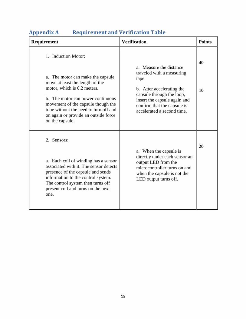
Appendix A Requirement and Verification Table
Requirement Verification Points
1. Induction Motor:
a. The motor can make the capsule
move at least the length of the
motor, which is 0.2 meters.
b. The motor can power continuous
movement of the capsule though the
tube without the need to turn off and
on again or provide an outside force
on the capsule.
a. Measure the distance
traveled with a measuring
tape.
b. After accelerating the
capsule through the loop,
insert the capsule again and
confirm that the capsule is
accelerated a second time.
40
10
2. Sensors:
a. Each coil of winding has a sensor
associated with it. The sensor detects
presence of the capsule and sends
information to the control system.
The control system then turns off
present coil and turns on the next
one.
a. When the capsule is
directly under each sensor an
output LED from the
microcontroller turns on and
when the capsule is not the
LED output turns off.
20
16
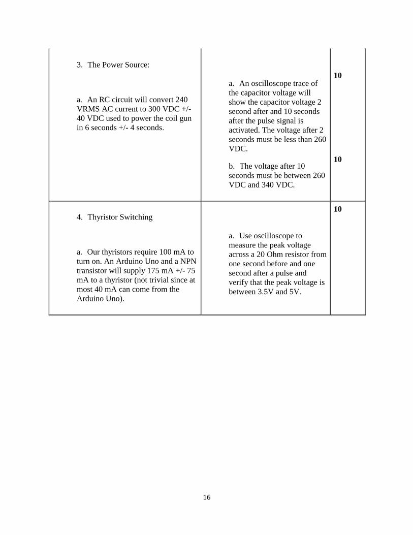
3. The Power Source:
a. An RC circuit will convert 240
VRMS AC current to 300 VDC +/-
40 VDC used to power the coil gun
in 6 seconds +/- 4 seconds.
a. An oscilloscope trace of
the capacitor voltage will
show the capacitor voltage 2
second after and 10 seconds
after the pulse signal is
activated. The voltage after 2
seconds must be less than 260
VDC.
b. The voltage after 10
seconds must be between 260
VDC and 340 VDC.
10
10
4. Thyristor Switching
a. Our thyristors require 100 mA to
turn on. An Arduino Uno and a NPN
transistor will supply 175 mA +/- 75
mA to a thyristor (not trivial since at
most 40 mA can come from the
Arduino Uno).
a. Use oscilloscope to
measure the peak voltage
across a 20 Ohm resistor from
one second before and one
second after a pulse and
verify that the peak voltage is
between 3.5V and 5V.
10

17
Appendix B Arduino Code
void setup ()
pinMode(2, OUTPUT);
pinMode(3, OUTPUT);
pinMode(4, OUTPUT);
pinMode(5, OUTPUT);
pinMode(6, OUTPUT);
pinMode(7, OUTPUT);
pinMode(13, OUTPUT);
Serial.begin(9600);
void loop()
int pulseDuration=50;
int threshold=100;
int val0=analogRead(A0);
int val1=analogRead(A1);
int val2=analogRead(A2);
int val3=analogRead(A3);
int val4=analogRead(A4);
int val5=analogRead(A5);
// Serial.println(val0);
// Serial.println(val1);
// Serial.println(val2);
// Serial.println(val3);
18
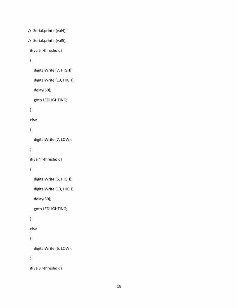
// Serial.println(val4);
// Serial.println(val5);
if(val5 >threshold)
digitalWrite (7, HIGH);
digitalWrite (13, HIGH);
delay(50);
goto LEDLIGHTING;
else
digitalWrite (7, LOW);
if(val4 >threshold)
digitalWrite (6, HIGH);
digitalWrite (13, HIGH);
delay(50);
goto LEDLIGHTING;
else
digitalWrite (6, LOW);
if(val3 >threshold)
19
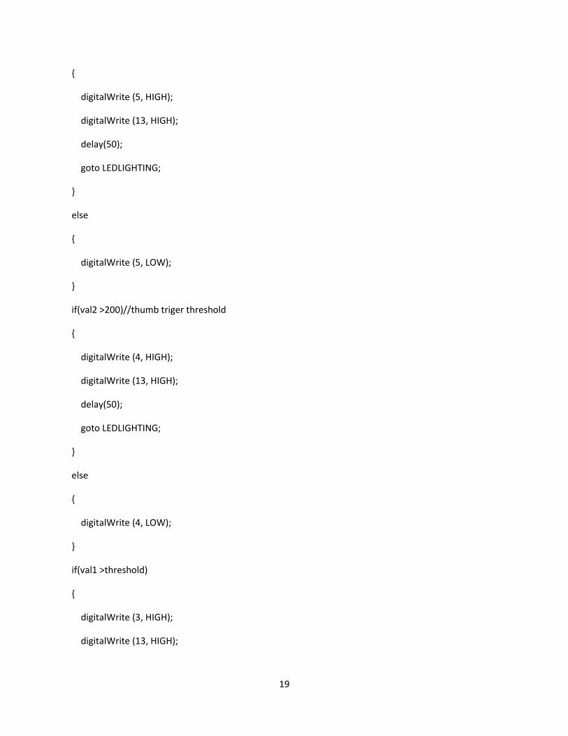
digitalWrite (5, HIGH);
digitalWrite (13, HIGH);
delay(50);
goto LEDLIGHTING;
else
digitalWrite (5, LOW);
if(val2 >200)//thumb triger threshold
digitalWrite (4, HIGH);
digitalWrite (13, HIGH);
delay(50);
goto LEDLIGHTING;
else
digitalWrite (4, LOW);
if(val1 >threshold)
digitalWrite (3, HIGH);
digitalWrite (13, HIGH);
20
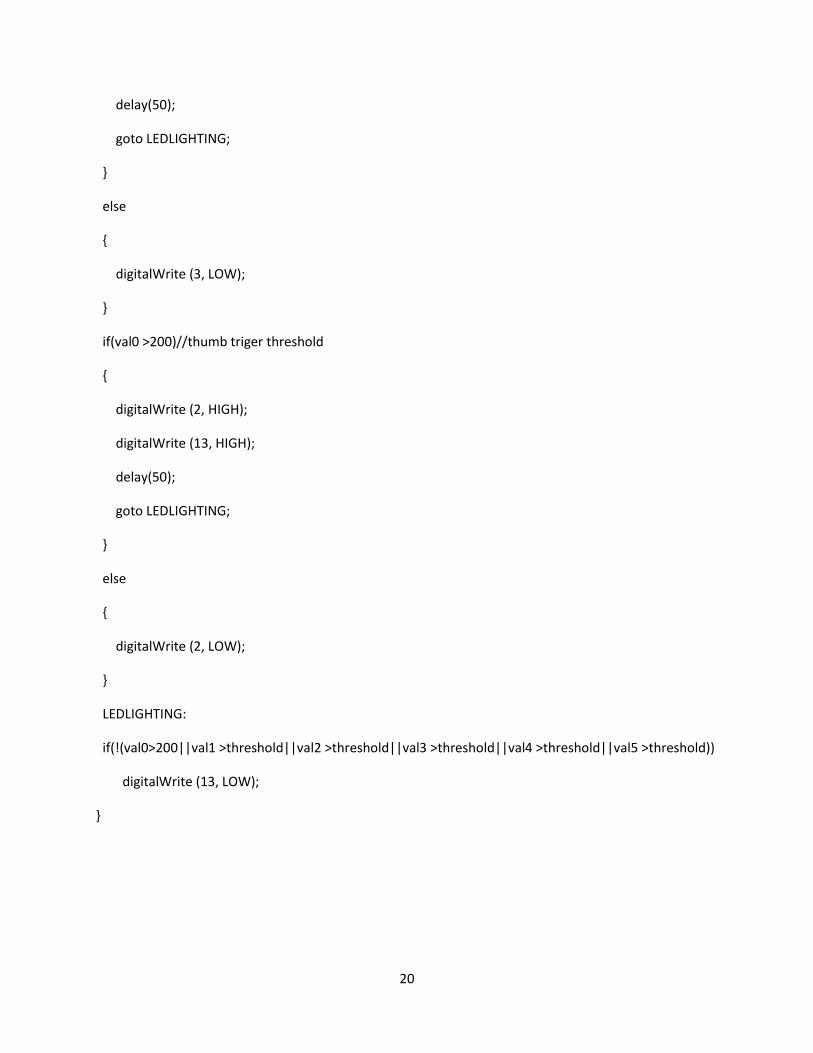
delay(50);
goto LEDLIGHTING;
else
digitalWrite (3, LOW);
if(val0 >200)//thumb triger threshold
digitalWrite (2, HIGH);
digitalWrite (13, HIGH);
delay(50);
goto LEDLIGHTING;
else
digitalWrite (2, LOW);
LEDLIGHTING:
if(!(val0>200||val1 >threshold||val2 >threshold||val3 >threshold||val4 >threshold||val5 >threshold))
digitalWrite (13, LOW);
Top Related