


Languages
Pages
Legal


Hydronic D4 (Ram Application)Installation, Troubleshooting & Repair Manual
Espar
February 2000
HYDRONIC D4 for DODGE RAM DIESEL ENGINES
Heater Model25 1917 01Installation is for 24 valve enginesKit CA 1917 31
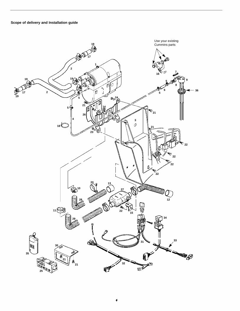
1 Hydronic heater2 Bracket3 Muffler/Exhaust4 7 day timer5 Inlet water hose6 Outlet water hose
1
2
3
4
5
6
*
24 Valve
Note: This install is for model years 1998- and up
For ease of install make sure the fuel tank isless than 1/4 tank full
Having a hoist will reduce install time andmake install easier.
Heater Warnings to Installer
• Correct installation of this heater is necessary to ensuresafe and proper operation. Read and understand this manu-al before attempting to install the heater. Failure to follow allthese instructions could cause serious or fatal injury
Explosion Hazard
• Heater must be turned off while re-fueling.• Do not install heater in enclosed areas where combustible
fumes may be present.
Fire Hazard
• Install the exhaust system so it will maintain a minimum dis-tance of 50mm(2”) from any flammable or heat sensitivematerial.
• Ensure that the fuel system is intact and there are no leaks.
Asphyxiation Hazard
• Route the heater exhaust so that exhaust fumes cannotenter any passenger compartments.
• If running exhaust components through an enclosed com-partment, ensure that it is vented to the outside.
Safety Hazard on Coolant Heaters Used With Improper Antifreeze Mixtures
• The proper operation of the Espar coolant heaters requiresthat the coolant in the system to be heated contain a propermixture of water and antifreeze to prevent coolant fromfreezing or slushing.
• If the coolant becomes slushy or frozen, the heater’s coolantpump cannot move the coolant properly causing a blockageof the circulating system. Once this occurs, pressurew i l l build up rapidly in the heater and the coolant hose couldeither burst or blow off at the connection point to the heater.
• This situation could cause engine damage and/or personali n j u r y. Extreme care should be taken to ensure a proper mix-ture of water and antifreeze is used in the coolant system.
• Refer to the engine manufacturer’s or coolant manufactur-er’s recommendations for your specific requirements.
Note: During electrical welding work on the vehicledisconnect the power to the heater in order to protect the control unit.
Note: The heater is equipped with a high voltage cutout as well a low voltage cutout.
Direct questions to Espar Heater Systems
USA 1-800-387-4800CDA 1-800-668-5676
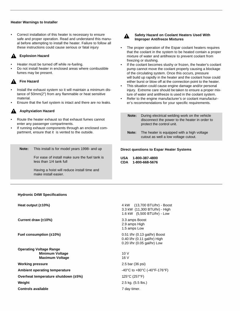
Hydronic D4W Specifications
Heat output (±10%) 4 kW (13,700 BTU/hr) - Boost3.3 kW (11,300 BTU/hr) - High1.6 kW (5,500 BTU/hr) - Low
Current draw (±10%) 3.3 amps Boost2.9 amps High1.5 amps Low
Fuel consumption (±10%) 0.51 l/hr (0.13 gal/hr) Boost0.40 l/hr (0.11 gal/hr) High0.20 l/hr (0.05 gal/hr) Low
Operating Voltage RangeMinimum Voltage 10 VMaximum Voltage 16 V
Working pressure 2.5 bar (36 psi)
Ambient operating temperature -40°C to +80°C (-40°F-176°F)
Overheat temperature shutdown (±5%) 125°C (257°F)
Weight 2.5 kg. (5.5 lbs.)
Controls available 7 day timer.

3
Espar’s 7 day timer is capable of setting up to 3 preset starttimes within 24 hrs. or 1 start time within 7 days. It also hasother functions such as a current time display and diagnosticcapabilities. Refer to instructions provided with timer for settingoptions.
7 day timer
HYDRONIC D4
Introduction
Espar’s Hydronic D4 heater offers an affordable heating solu-tion for small trucks, particularly for Dodge Ram users. Its com-pact size enables a simple installation and eliminates the needfor electrical plug-ins. The heater is quality engineered to pro-vide a dependable means of heating and is capable of puttingout between 5,500 to 13,700 BTU’s/hr. It features automaticheat regulation while being fuel and power efficient.
The heater pumps coolant from the engine, heats it and returnsit to the engine. By routing the hot coolant through the vehiclesheat exchanger it is also possible to heat the interior of thevehicle.
Since the heater runs on diesel fuel using 12 volt power, it isable to operate completely independent of the vehicle engine.A temperature regulating switch in the unit regulates the coolanttemperature between a low of 65°C (149°F) and a high of 80°C(176°F) by automatically cycling the heater.
The Hydronic D4 is controlled from the vehicle cab by a timerwhich can be set to come on from up to 7 days in advance.
A flame sensor, temperature regulating and overheat switch areamong the safety features which make the Hydronic D4 a safeand dependable heating system.
Water outlet
Exhaustoutlet
Combustion air
Fuel metering pump
Water inlet
Fuel inletCombustion air blower
Overheat sensor
Glow pin
Combustion chamber
Heat exchanger
Flame sensor
Temperature sensor
Control unit
Water pump
Note: For ease of install, please follow instructions insequence. All circled numbers indicate prepa-ration steps.
4
Scope of delivery and Installation guide
1
2
2
16
34
5
5
5
7
8
9
10
11
12
13
14
15
17
17
18
19
19
19 19
20
21
36
21
21
21
22
22
22
23
27
28
29
3031 33
34
32
25
35
26
24
22
22
21
21
5
6
Use your existingCummins parts

1 Remove negative terminals from the two batteries
2 For ease of install jack up vehicle and remove front wheelon drivers side.
3 Remove starter motor by removing 3 (10mm 12pt) boltsfrom starter - let starter hang down from battery cables.
4 Locate the lift pump (engine block-driver side-lower rear),remove the straight banjo fuel fitting off the lift pump. Use17mm wrench to remove banjo bolt, being careful of the 2washers on the bolt. Squeeze tabs on the lock to removethe fuel line from the banjo fitting. A 90° banjo fuel fittingwill be installed after the frame bracket has been installed.
5 In the driver side wheel well remove existing bolts holdingbrake line support bracket. Thread bolt hole #2 with a pre-viously removed factory bolt ...continued
5
Scope of delivery
Description Part Number
1 12V Hydronic D4 heater 25 1917 01
2 Coolant hose 20mm 25 1917 80 00 01
3 Frame bracket CA0 10 086
4 Plastic fuel line 2mm ID 090 31 117
5 Clamp 9mm 10 2063 00 90 98
6 Fuel hose 3.5mm ID 360 75 300
7 Dust cap CA0 12 050
8 Fuel pipe reducer CA0 12 092
9 Fuel pick-up assembly CA0 12 093
10 Clamp 16-25mm ID 10 2064 01 60 25
11 Clamp 26mm 152 61 102
12 End sleeve 24mm exhaust 25 1482 80 00 01
13 End sleeve with crossbar 25 1688 80 12 01
14 Spacer mounting bracket 25 1864 80 00 02
15 Bracket muffler CA0 10 087
16 Banjo fuel fitting CA0 12 101
17 Reducing pipe 20 1645 89 00 06
18 Cable ties CA1 00 005
Description Part Number
19 Hose clamp CA1 10 038
20 Intake clamp CA1 10 052
21 Bolt M6x12 CA3 00 103
22 Spin lock bolt CA3 000140
23 Hex nut M6 CA3 00 208
24 Spring washer `CA3 00 308
25 7 day timer 22 1000 30 36 00
26 Saddle Bracket 25 1864 80 00 01
27 Muffler 25 1864 81 01 00
28 Air intake hose 360 00 099
29 Flex. exhaust 360 61 550
30 Bracket for 7day timer CA0 10 061
31 Engine compartment harness CA1 60 403
32 Dash harness CA1 60 405
33 Grommet 20 1280 09 01 03
34 Relay 12V 203 00 065
35 Remote Heater Starter (optional) CA1 00 150
36 Grommet for sending unit CA0 12 093-003(2000 model and up only)
Preparation / Bracket Installation / Heater Mount
Starter motor
10mm 12pt bolt
Brake bracket
Clip
4
3
5

6 To slide frame bracket into position, use a pry bar or largescrew driver to lift the brake line support bracket awayfrom the frame rail. Slide bracket behind brake lines sothat the Frame bracket sits behind the brake line supportbracket at bolt #4; and in front of brake line bracket atbolts #2 and #3. See graphics. When bracket has beenslid into position install Espar supplied bolt at #2 - fingertight then install bolts #1 through 4 supplied with kit - usea standard wrench to tighten bolts till snug.
7 Install saddle bracket onto Espar frame bracket using 4nuts and bolts supplied in kit (Radius of bracket facingdown, see graphic). Tighten.
8 Thread bolt and spacer provided with kit into threadedhole in the side of heater. Slide heater from the topsideinto saddle bracket, (heater water outlets facing towardsthe front of the truck) and snap into place. Tighten boltwith spacer. Use hole in center of frame bracket to accessbolt. Insert bolt into opposite side of heater and tighten.Heater is now mounted and secure.
Note: You will have to slightly push brake lines outof the way. (on four wheel ABS)
6
bolt #2
bolt #1
bolt #3
bolt #4
Espar bracket is slid on top of brakeline support bracket at this point
Sits beneathbrake linebracket
Sits on topof brakelinebracket
Over tightening will pull thread out of frame
Bolt and Spacer
Water in
Bolt
Water out
Fuel intake
Saddle bracket
Frame mount
Espar Heater on Bracket Steering column
6
7
8
7
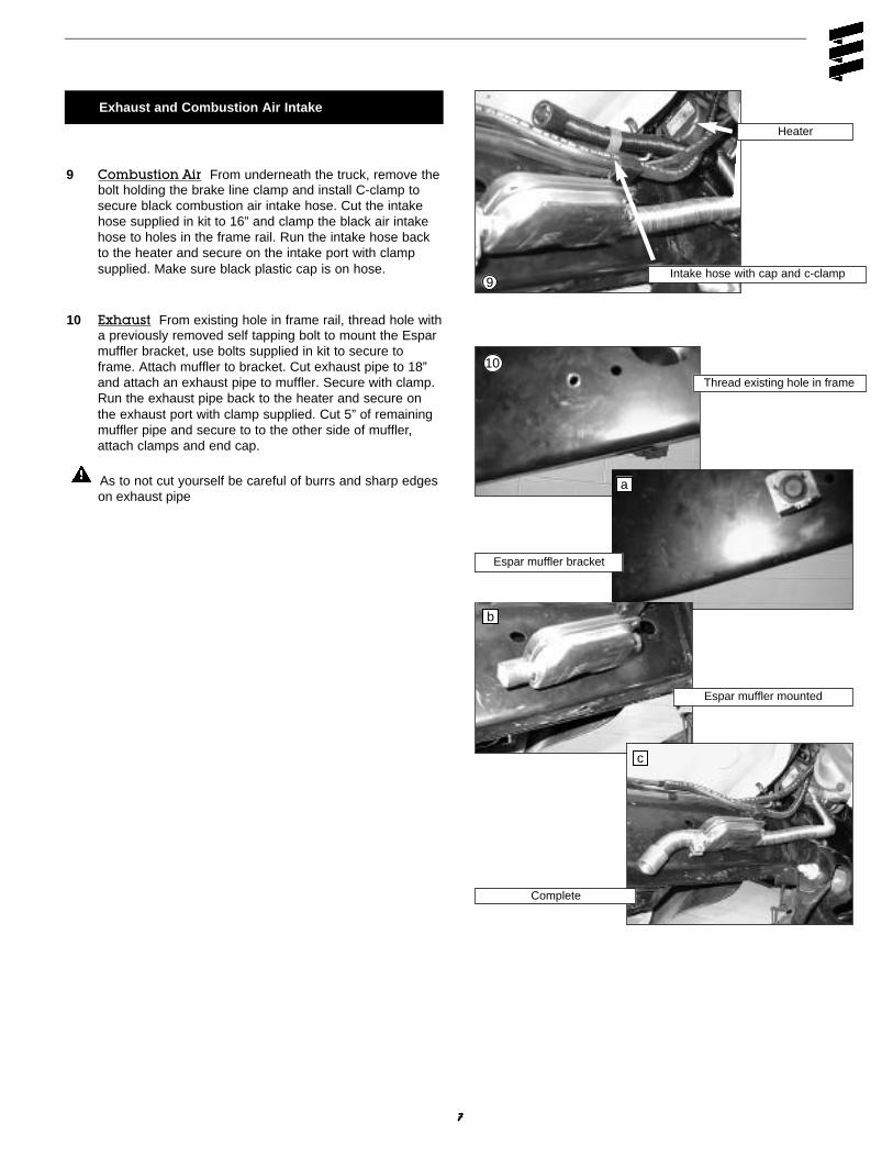
Exhaust and Combustion Air Intake
9 Combustion Air From underneath the truck, remove thebolt holding the brake line clamp and install C-clamp tosecure black combustion air intake hose. Cut the intakehose supplied in kit to 16” and clamp the black air intakehose to holes in the frame rail. Run the intake hose backto the heater and secure on the intake port with clampsupplied. Make sure black plastic cap is on hose.
10 Exhaust From existing hole in frame rail, thread hole witha previously removed self tapping bolt to mount the Esparmuffler bracket, use bolts supplied in kit to secure toframe. Attach muffler to bracket. Cut exhaust pipe to 18”and attach an exhaust pipe to muffler. Secure with clamp.Run the exhaust pipe back to the heater and secure onthe exhaust port with clamp supplied. Cut 5” of remainingmuffler pipe and secure to to the other side of muffler,attach clamps and end cap.
As to not cut yourself be careful of burrs and sharp edgeson exhaust pipe
Thread existing hole in frame
Espar muffler bracket
Espar muffler mounted
Complete
Intake hose with cap and c-clamp
Heater
a
b
c
9
10
8
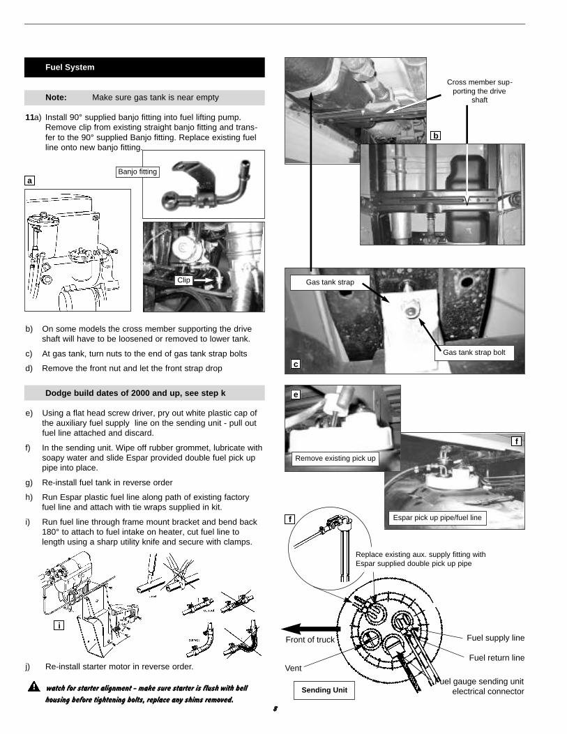
Fuel System
Note: Make sure gas tank is near empty
11a) Install 90° supplied banjo fitting into fuel lifting pump.Remove clip from existing straight banjo fitting and trans-fer to the 90° supplied Banjo fitting. Replace existing fuelline onto new banjo fitting.
b) On some models the cross member supporting the driveshaft will have to be loosened or removed to lower tank.
c) At gas tank, turn nuts to the end of gas tank strap bolts
d) Remove the front nut and let the front strap drop
Dodge build dates of 2000 and up, see step k
e) Using a flat head screw driver, pry out white plastic cap ofthe auxiliary fuel supply line on the sending unit - pull outfuel line attached and discard.
f) In the sending unit. Wipe off rubber grommet, lubricate withsoapy water and slide Espar provided double fuel pick uppipe into place.
g) Re-install fuel tank in reverse order
h) Run Espar plastic fuel line along path of existing factoryfuel line and attach with tie wraps supplied in kit.
i) Run fuel line through frame mount bracket and bend back180° to attach to fuel intake on heater, cut fuel line tolength using a sharp utility knife and secure with clamps.
j) Re-install starter motor in reverse order.
watch for starter alignment - make sure starter is flush with bell
housing before tightening bolts, replace any shims removed.
Gas tank strap
Gas tank strap bolt
Sending Unit
Fuel return line
Fuel supply line
Fuel gauge sending unitelectrical connector
Vent
Replace existing aux. supply fitting withEspar supplied double pick up pipe
Front of truck
Cross member sup-porting the drive
shaft
Clip
Espar pick up pipe/fuel line
Remove existing pick up
Banjo fittinga
b
c
e
f
f
i

Plumbing
12 Find center of plumbing hose supplied in kit and cut inhalf. For a perfect fit, heater hose can be trimmed at ends.
13 Clamp coolant hoses to the heater ports of the heater andrun heater hoses over the cylinder head to the inlet hoseof the heat exchanger (passenger side). Attach waterclamp pliers (2) to existing hose (inlet hose of the heatexchanger) running into firewall. Slice inlet hose in two and install reducers provided in kit,attaching with hose clamps provided. Installplumbing as shown in diagram to ensureproper coolant flow.
14 Secure coolant lines with clamps provided.
k) For Dodge 2000 and up build dates: The sending unit hasbeen modified. To adapt for this you will need to drill a40mm (1 9/16”) hole in the sending unit at the postionshown in illustration k (x marks the spot). A grommet, sup-plied in kit should then be inserted into the hole and theespar pick-up pipe can then be slid into place. Espar fuel nipples shouldface between the 11 and12 o’clock position.Return to step g.
9
Water inlet hose to heater
Water outputhose from heater
To engine
Water inlet to heatexchanger in cab
Reducer
Reducer
Fire wall(passenger side)
Espar fuel nipplesshould face the 11to 12 o’clock postion
Grommet
Bleed screw
Coolant from heatingcore back to engine
Coolant fromengine to heat-ing core. (inlethose to heatexchanger.)
12
13
k
Sending Unit
Front of truck

10
Electrical Wiring
15 Timer can be mounted anywhere inside cab. Espar rec-ommends under the dash on passenger side.
a) From inside cab remove the 3 screws from knee bolster atdash (drivers side) and locate a suitable place to drillthrough the firewall. The 2 sheet metal screws make for agood reference. If at all possible use existing factory hole.
b) Drill a 17.5mm (3/4”) hole in the firewall at driver side andfeed engine compartment harness through so that bare ter-minals of engine compartment harness are protrudingthrough to the inside of vehicle. Secure grommet in firewalland make connection at heater.
Do not attach wires to battery. This will be done at a laterstage.
c) Run relay mounting block and fuse block from engine com-partment harness to the vehicle fuse box on drivers sidewheel well. Drill 1/8” hole in fenderwell to accommodatefuses. Drill second hole after mounting. Secure relay andfuse block to engine compartment with self tapping screwsprovided. Secure covers on blade fuses.
d) When mounting timer under dash - remove glove box andfeed dash harness wires back across to drivers side, tiewrap and run over steering column.
e) Take the 2 prong connector and the 4 prong connectorfrom the dash harness and match them up to the terminalson the engine compartment harness that had been runthrough the fire wall.
2 prong -black, black/violet. 4 prong -red, yellow, brown, blue/white.
Install terminals into connectors of engine compartmentharness and match to corresponding positions of dashharness. Make connections.
f) Using a test light to verify, locate a run and accessories12V source from junction box (driver side). The blue wire atjunction box has proven to be one.Verify this.
g) Attach red clam shell connector provided in kit to the runand accessories wire and insert pink male spade connectorfrom dash harness to clam shell connector.
Preferable timer mount
Remove Knee bolster
Reference - 2 screws
Hole in firewall drivers side
Glove box with dash harness
Clam shell connector with spade connector
Switch, Main and Blower fuses
Relay mounting block
a
a
b
c
f
d
15

11
h) Drill 2 holes under dash to accommodate 7-day timerbracket. Bolt bracket down using hardware supplied.
i) Feed wires with terminal block through the bracket andconnect to timer.
j) Slide and lock timer into bracket
k) Run remaining black and black/violet stripe wires with con-nectors to the vehicle blower motor (passenger side under-neath dash). Disconnect the connectors at vehicle blowermotor and insert the Espar connectors.
l) Re-install dash in reverse order
m) Connect positive (+) red wire with ring terminal from enginecompartment harness onto the positive post in fuse panelon fender well. Connect brown negative (-) wire with ringterminal from engine compartment harness onto the nega-tive post of battery.
Bracket positioned under dash
7 day timer socket connection
Blower connectors
Vehicle fuse box
Note: To paint the 7 day timer bracket to match theinterior; refer to the tune-up decal locatedunder the hood. Secondary color is the interi-or. Contact manufacturer for recommendedpaint applications.
h
i
j
k
m

12
1.1 Blower motor1.2 Glow pin1.5 Overheat sensor1.12 Flame sensor1.13 Temperature sensor2.1 Control unit2.2 Fuel metering pump2.7 25 amp main fuse2.8 20 amp vehicle blower fuse2.9 5 amp timer fuse3.2.9 7 day timer5.1 Battery6 Remote Heater Starter
(optional)
Hydronic D4 - Dodge Ram Application
Wiring Diagram
Model 25 1917 01
Heater Interior
Optional RemoteHeater starterP/N: CA0 00 150
6

13
Read carefully to ensure no engine damage
16 Fill radiator as high as possible, open bleed screw onheater until water flows out continuously (15-30 secs.) -close screw.
17 At timer - press clock button twice to stop clock fromflashing, push on/off switch to activate heater, the yel-low indicator will come on in the switch to show it’s activat-ed and 7 day timer will read 120 minutes. Heater will takefrom 1-3 minutes to start on the first attempt ( this isbecause the fuel pump has to draw fuel for the first timefrom the fuel tank). Once heater is running you’ll see asmall decrease in the level of your coolant at the radiator.Fill radiator as needed until coolant is replenished. Thistakes approximately 15-20 minutes. Your system is nowbled and you can now replace radiator cap. Turn heateroff.
18 Start truck and hold engine to 1500-2000 r.p.m. for 1-2 min-utes, this will ensure that you have bled fuel system of airbubbles from removing and replacing the fuel fitting.
Installation is now complete
Read instructions on 7-day timer to preset times for heaterrun times and general information. Set the time first so thatprogrammed times align themselves correspondingly. If atany time work is done on the heater and power is discon-nected please reset timer to correct time if programmedtimes are to work.
Bleeding Instructions
Bleed screw
Periodic Maintenance
• Visual check of all fuel lines for leaks. Check and if necessary replace fuel filter inserts.
• Visual check of electrical lines and connections for corrosion.• Run your heater at least once a month during the year
(for a minimum of 15 minutes).• Maintain your batteries and all electrical connections in
good condition. With insufficient power the heater will notstart. Low and high voltage cutouts will shut the heaterdown automatically.
• Use fuel suitable for the climate (see engine manufacturersrecommendations). Blending used engine oil with diesel fuel is not permitted.
• Check the glow pin and replace if necessary.
Troubleshooting
In the event of failure there are several items which should be checked first before any major troubleshootingis done. Check:
• Circuit breakers and fuses. • Electrical lines and connections • For interference in Combustion air and Exhaust pipes.• That there is fuel in the tank.• Battery voltage
Self Diagnostics
The heater is equipped with selfdiagnostic capability. You canretrieve information on theheaters last 5 faults using theEspar 7 day timer . Espar’s 7 day timer has a fault coderetrieval device built into the unit. This function automaticallyactivates if the heater is experiencing problems.
• Fault codes appear on the LCD display screen• Codes can be translated from the charts on the following
pages.

14
Fault Code Fault Description Causes / Repair
000 Normal Operation
010 Overvoltage Check voltage between terminals 1(red) and 2(brown) at connector. This must be less than 15.9 volts.Check vehicle charging system.
011 Under voltage shut down Check voltage between terminals 1(red) and 2(brown) at connector. This must be greater than 10.2 voltsCheck batteries and connections.
012 Overheating Check for possible causes of overheat (water circuit), Sensor.Check overheat switch resistance values. Temperature at temperature sensor or overheat sensor is greater than 125°C
014 Possible overheating detected Difference of measured values at temperature sensor >15°C(difference evaluation) (min. 70°C water temperature and metering pump in
operation); Check temperature sensor and overheating sensor,replace if necessary.
015 Too many overheats Remove cause of over heat. Reset control unit using 7 day timer or fault code retrieval device to unlock control unit.
020 Open circuit - glow pin Check glow pin, replace if necessary
021 Short circuit - glow plug Check glow pin, replace if necessary
030 Combustion air blower motor Blower impeller or electric motor jammed (frozen solid, dirty,etc.) Remedy jam, replace electric motor if necessary
031 Combustion air blower motor Check lead to combustion air motor for continuity, replace motor if necessary
032 Combustion air blower motor short-circuit Check combustion air blower motor (electric motor); replace if necessary. Check power supply (chafed, corroded etc.)
041 Water pump break Check supply lead to water pump for continuity, remedy break, replace water pump if necessary
042 Water pump short-circuit Check supply lead to water pump for short circuit, check water pump, replace water pump if necessary
047 Short circuit - fuel metering pump Check for wires for short to fuel metering pump. Test fuel metering pump. Replace if necessary
048 Open circuit - fuel metering pump Check supply lead to metering pump for continuity, remedy break, replace if necessary
050 Too many no start attempts Safety time counter reading exceeded. Reset control unit using 7 day timer or fault code retrieval device to unlock control unit
051 Faulty flame recognition At start, if flame sensor is a above 70°C > 240 seconds; check exhaust gas and combustion air supply, check flame sensor,replace if necessary.
052 No start safety time exceeded No flame detected on start attempt.Check fuel delivery and fuel supply, Check exhaust gas and combustion air ducts
053 Flame cutout in boost mode Heater has started successfully the flame has extinguished. Check fuel supply. Check combustion air and exhaust flow.Check flame sensor resistance value. Replace flame sensor if necessary

15
Fault Code Fault Description Causes / Repair
054 Flame cutout in high mode Heater has started successfully the flame has extinguished.Check fuel supply. Check combustion air and exhaust flow.
056 Flame cutout in low mode Check flame sensor resistance value.
060 Open circuit - temperature sensor Temperature sensor detects a value beyond it's range. Check connections. Check sensor resistance values between 11 and 12 at connector B2 > 2 MΩ (if open circuit)
061 Short circuit - temperature sensor Check connections. Check sensor resistance values between 11 and 12 at connector B2< 50 MΩ (if short circuit)
064 Open circuit - flame sensor Sensor is sensing value outside of range. Check connection leads. Resistance values between 13 and 14 at connectorB2 > 3040 Ω (if open circuit)
065 Short circuit - flame sensor Check connection leads. Resistance values between 13 and 14 at connector B2 < 780 Ω (if short circuit).
071 Open circuit - overheat sensor Check connection leads. Resistance values between 9 and 10 at connector B2 > 2 MΩ (if open circuit)
072 Short circuit - overheat sensor Check connection leads. Resistance values between 9 and 10 at connector B2 < 50 MΩ (if short circuit)
090 Control unit defect (internal fault) Control unit malfunction due to interference voltage from092 Control unit defective(ROM error) vehicle electrical system; possible causes low batteries, 093 Control unit defective(RAM error) charges, other sources of interference, eliminate interference
voltages. Internal faults detected in microprocessor/ memory detected. Replace control unit
097 Control unit defective (power failure) Internal failure. Replace control unit
099 Control unit defective (eeprom error) Exchange the control unit100101102103

1 Cover, metering pump
2 Water pump assembly
When mounting, place O-rings on connection on waterpump housing
3 Metering pump and bracket
16
Fuel Quantity Test
The fuel Quantity should be tested if the heater has difficultystarting or maintaining a flame.
Note: Measure the fuel quantity when the battery iss u fficiently charged. At least 11V and at most 13V should be applied at the control unit during measurement.
Preparation
• Remove metering pump cover
• Pull the fuel line off the combustion chamber and insert into a graduated measuring glass
• Switch the heater on, when fuel delivery is uniform (approximately 40 seconds after switching on), the fuel lineis full and bled.
• Switch heater off
• Empty measuring glass and replace
Repair Steps
Disassembly / Assembly
1 Cover, metering pump2 Water pump, assembly3 Metering pump and bracket4 Cover, blower5 Control unit and cover6 Glow pin7 Flame sensor8 Cable harness9 Electric motor, complete10 Combustion chamber with flame tube11 Heat exchanger and jacket
Measurement
• Switch heater on
• Fuel delivery stars automaticallyapproximately 40 seconds afterswitching on
• Hold the graduated measuringglass at the glow pin height dur-ing measurement
• After 90 seconds of fuel delivery,it will shut off automatically
• Switch heater off.
• Read off quantity of fuel deliveryin the graduated measuringglass
Evaluation
Nominal value - max.7.5 cm3 / 90 seconds
- min. 6.5 cm3 / 90 seconds
If measured quantity of fuel is o v e r or u n d e r the nominal value,the metering pump must be replaced or fuel restriction eliminated

17
4 Cover, blower 5 Control unit and cover
6 Glow pin 7 Flame sensorFor removal of tab receptacles, use AMP extractor tool
8 Cable Harness 9 Electric motor, complete
10 Combustion chamber with flame tube 11 Heat exchanger and jacketAlign slot on heat exchanger (arrow) with lug in jacket

18
Parts Diagram
HYDRONIC D4W
Model 25 1917

19
Ref.
No. Description Part Number
1 Outer casing 25 1917 01 01 01
2 Combustion air blower with cover 25 1917 99 15 00
3 Cover 25 1917 01 00 02
4 Burner 25 1917 19 00 00
5 Heat exchanger 25 1864 06 00 01
6 Control unit 25 1917 51 00 04
7 Cover 25 1864 01 00 03
8 Water pump 25 1917 99 25 00
9 Fuel metering pump 25 1917 45 00 00
10 Strainer 20 1312 00 00 06
11 Holder for fuel metering pump 25 1917 01 00 07
12 Seal 25 1864 99 00 21
13 O-ring 25 1864 99 00 23
14 Glow pin 25 1864 01 10 00
15 Flame sensor 25 1864 35 00 00
16 Cable section with overheat & temperature sensors, glow plug and main connectors 25 1917 01 12 00
17 Cable section with overheat & temperature sensors 25 1917 01 13 00
18 Spring leaf 25 1864 01 00 05
19 Cover fuel metering pump 25 1917 01 00 03
20 O-ring 320 75 105
21 O-ring 25 1864 99 00 30
22 Fuel hose 360 75 292
23 Hose clip 10 2063 00 70 78
24 Hose clip 103 10 087
25 Bleed screw 25 1017 25 00 11
26 Washer Hardware
27 Tapite screw 25 1864 99 00 24
28 Spring washer 171 22 112
29 Hexagon nut 110 10 024
30 Grommet 25 1917 01 00 05
31 Cover 20 1673 25 01 01
32 Tapite screw 109 10 027
33 Tapite screw 25 1864 99 00 28
34 Bolt 25 1864 99 00 26
35 Tapite screw 25 1864 99 00 29
36 Tapite screw 25 1864 99 00 27
37 Counter sunk screw 25 1864 99 00 25
38 Rubber boots 320 31 120
HYDRONIC D4W Description & Part #’s

1st. Printing - November 1998
Printed in Canada
P/N: 610-123-1098
Espar Products, Inc.
6435 Kestrel RoadMississauga, Ontario
Canada L5T 1Z8
9675 Harrison Rd, Suite 102Romulus, Michigan
48174U.S.A.
Canada (Tel): 905-670-0960800-668-5676
Fax: 905-670-0728
U.S. (Tel): 800-387-4800
Member of the Worldwide Eberspächer GmbH Group of Companies
Top Related