


Languages
Pages
Legal

67
0738-8551/01/$.50© 2001 by CRC Press LLC
Critical Reviews in Biotechnology, 21(2):67–110 (2001)
Hydrodynamic Damage to Animal Cells
Yusuf ChistiInstitute of Technology and Engineering, Massey University, Private Bag 11 222, Palmerston North,New Zealand. Telephone: +64-6-356-9099 ext. 2911. Fax: +64-6-350-5604. E-mail address:[email protected]
Table of Contents
I. Introduction ............................................................................................. 68
II. Shear Forces in Process Equipment ................................................... 68
A. Gas-Agitated Bioreactors .................................................................. 69
B. Mechanically Stirred Vessels ............................................................ 73
C. Pipework and Flow Channels ........................................................... 74
D. Turbulent Jets ................................................................................... 79
E. Shear Phenomena in Isotropic Turbulence ...................................... 81
F. Effects of Suspended Particles on Turbulence ................................ 84
III. Shear Effects on Cells ........................................................................... 84
A. Suspended Cells ............................................................................... 84
1. Hybridomas and Suspension-Adapted Cells ............................. 84
2. Blood Cells ................................................................................. 91
B. Adherent Cells .................................................................................. 94
1. Cells on Stationary Surfaces ..................................................... 94
2. Cells on Suspended Microcarriers ............................................. 95
C. Shear Effects on the Cell Cycle ..................................................... 102
IV. Concluding Remarks .......................................................................... 102
68
V. Nomenclature ....................................................................................... 104
References ......................................................................................................... 105
ABSTRACT: Animal cells are affected by hydrodynamic forces that occur in culture vessel, transferpiping, and recovery operations such as microfiltration. Depending on the type, intensity, and durationof the force, and the specifics of the cell, the force may induce various kinds of responses in the subjectcells. Both biochemical and physiological responses are observed, including apoptosis and purelymechanical destruction of the cell. This review examines the kinds of hydrodynamic forces encoun-tered in bioprocessing equipment and the impact of those forces on cells. Methods are given forquantifying the magnitude of the specific forces, and the response thresholds are noted for thecommon types of cells cultured in free suspension, supported on microcarriers, and anchored tostationary surfaces.
KEY WORDS: animal cell culture, bioreactors cell damage, erythrocytes, shear effects.
I. INTRODUCTION
Human and animal cell cultures are widelyused to produce vaccines, therapeutic proteins,and diagnostic antibodies.1,2 Advances in tissueregeneration from in vitro cultured cells prom-ise to further expand the demand for cell cul-ture processes, and additional explosive growthis likely as methods are established for gener-ating functional organs such as heart and kid-ney from cells.
Cells are delicate. Culture and processingof cells invariably expose them to variouslyintense hydrodynamic forces. A sufficientlyintense force will destroy cells outright, whilea force of lesser magnitude may induce variousphysiological responses, including death, with-out necessarily causing any obvious physicaldamage. This review examines the nature ofthe forces encountered in bioprocessing andthe effects of these forces on cells. The discus-sion considers freely suspended cells and thoseanchored to suspended microcarriers and sta-tionary surfaces. Following convention, themany kinds of damaging forces are collectivelyreferred to here as “shear forces”, even thoughthe damage many not be always attributable toshear stress or shear rate. The focus is only onthe damaging phenomena that cannot be as-
cribed to gas bubbles. The damaging effects ofsparging with a gas have been treated compre-hensively in several other reviews.3-9
II. SHEAR FORCES IN PROCESSEQUIPMENT
Substantial information exists on the ef-fects of hydrodynamic forces on cells in de-fined flow geometries such as viscometers andcapillaries,3,10-16 but little is known about shearfields in bioreactors17-19 and other process equip-ment such as pumps and valves. Whereas se-lection of more shear-tolerant cell lines can behelpful, successful culture of shear-sensitivebiocatalysts requires attention to bioreactordesign and operation. In many cases, the needto prevent cell lysis persists beyond thebioreactor culture step and into various stagesof downstream processing, even when the cellsare not the final product. Unwanted cell lysismakes purification of extracellular secretedproducts difficult. In addition, stability of anextracellular protein product may be severelycompromised by contact with large amounts ofproteases that are released from lysing cells.20,21
Premature lysis may cause other processingproblems. One example of shear-related viabil-
69
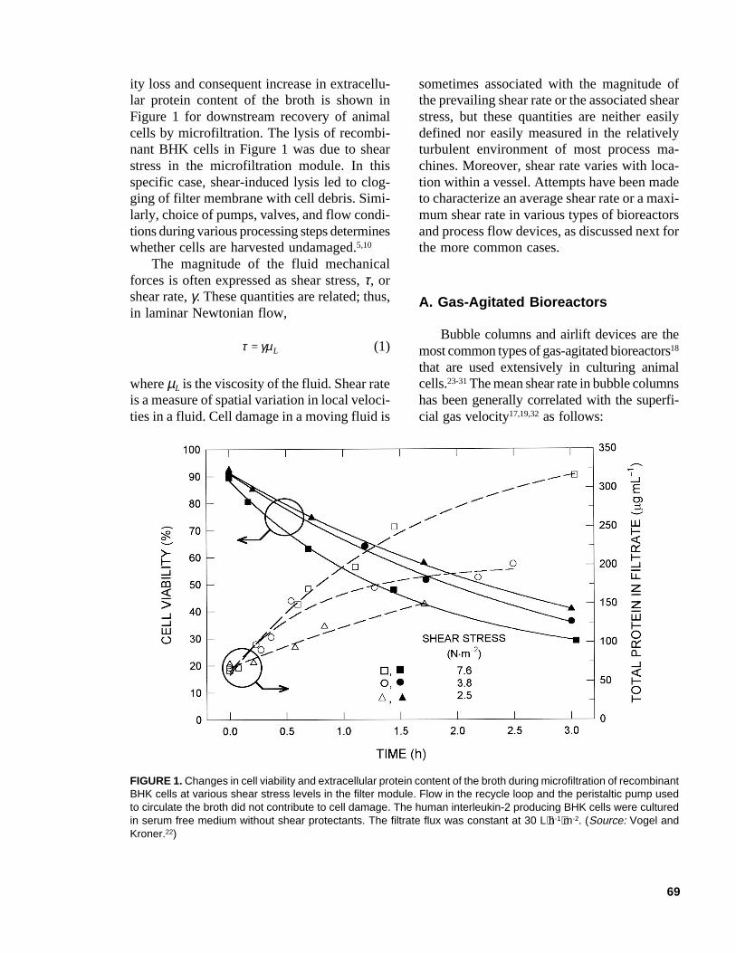
ity loss and consequent increase in extracellu-lar protein content of the broth is shown inFigure 1 for downstream recovery of animalcells by microfiltration. The lysis of recombi-nant BHK cells in Figure 1 was due to shearstress in the microfiltration module. In thisspecific case, shear-induced lysis led to clog-ging of filter membrane with cell debris. Simi-larly, choice of pumps, valves, and flow condi-tions during various processing steps determineswhether cells are harvested undamaged.5,10
The magnitude of the fluid mechanicalforces is often expressed as shear stress, τ, orshear rate, γ. These quantities are related; thus,in laminar Newtonian flow,
τ γµ= L (1)
where µL is the viscosity of the fluid. Shear rateis a measure of spatial variation in local veloci-ties in a fluid. Cell damage in a moving fluid is
sometimes associated with the magnitude ofthe prevailing shear rate or the associated shearstress, but these quantities are neither easilydefined nor easily measured in the relativelyturbulent environment of most process ma-chines. Moreover, shear rate varies with loca-tion within a vessel. Attempts have been madeto characterize an average shear rate or a maxi-mum shear rate in various types of bioreactorsand process flow devices, as discussed next forthe more common cases.
A. Gas-Agitated Bioreactors
Bubble columns and airlift devices are themost common types of gas-agitated bioreactors18
that are used extensively in culturing animalcells.23-31 The mean shear rate in bubble columnshas been generally correlated with the superfi-cial gas velocity17,19,32 as follows:
FIGURE 1. Changes in cell viability and extracellular protein content of the broth during microfiltration of recombinantBHK cells at various shear stress levels in the filter module. Flow in the recycle loop and the peristaltic pump usedto circulate the broth did not contribute to cell damage. The human interleukin-2 producing BHK cells were culturedin serum free medium without shear protectants. The filtrate flux was constant at 30 L⋅h-1⋅m-2. (Source: Vogel andKroner.22)
70
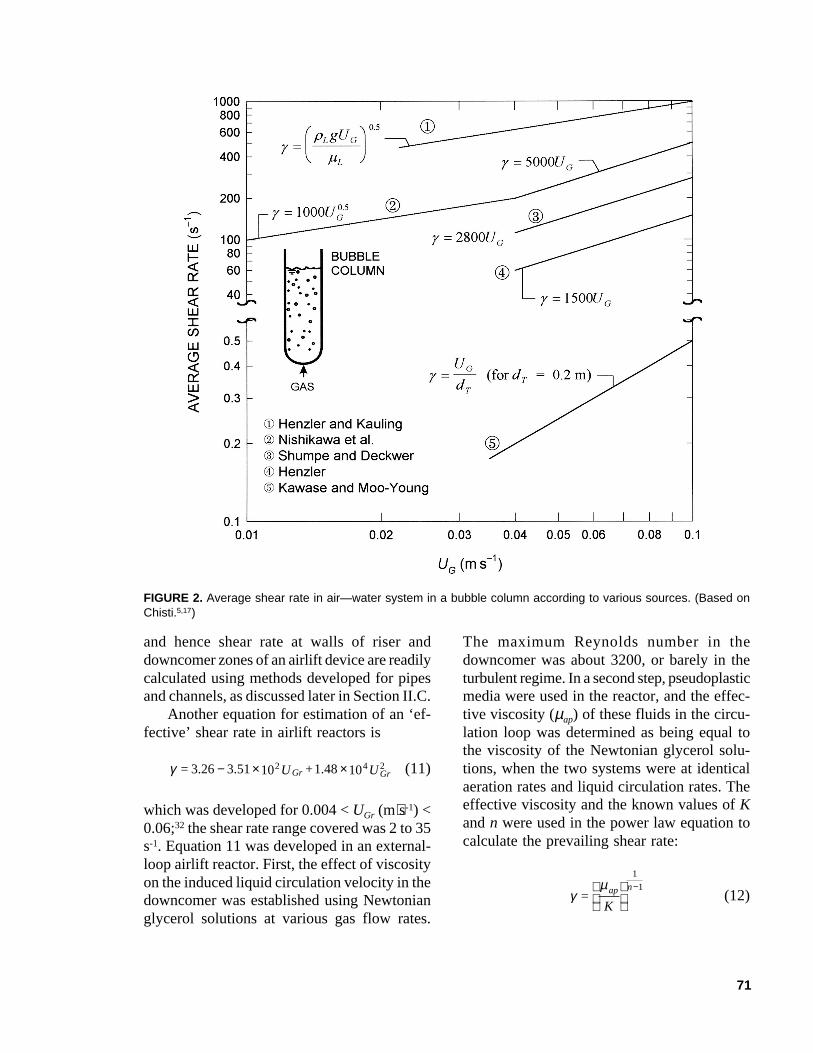
γ = kUGa (2)
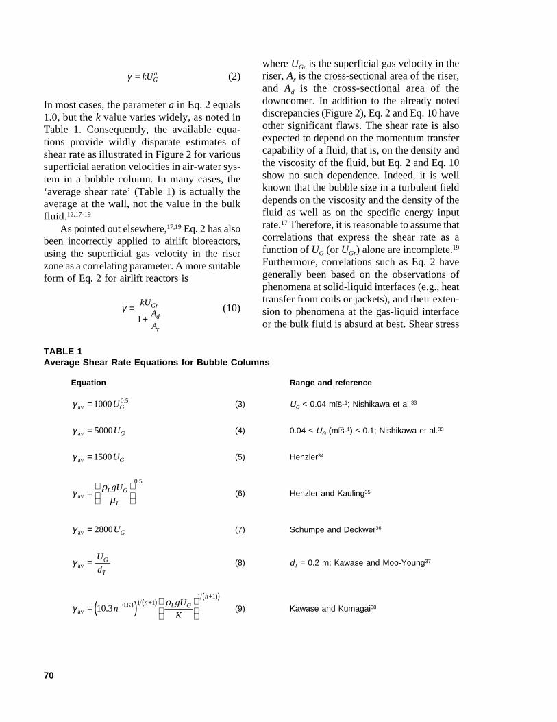
In most cases, the parameter a in Eq. 2 equals1.0, but the k value varies widely, as noted inTable 1. Consequently, the available equa-tions provide wildly disparate estimates ofshear rate as illustrated in Figure 2 for varioussuperficial aeration velocities in air-water sys-tem in a bubble column. In many cases, the‘average shear rate’ (Table 1) is actually theaverage at the wall, not the value in the bulkfluid.12,17-19
As pointed out elsewhere,17,19 Eq. 2 has alsobeen incorrectly applied to airlift bioreactors,using the superficial gas velocity in the riserzone as a correlating parameter. A more suitableform of Eq. 2 for airlift reactors is
γ =+
kUA
A
Gr
d
r
1(10)
where UGr is the superficial gas velocity in theriser, Ar is the cross-sectional area of the riser,and Ad is the cross-sectional area of thedowncomer. In addition to the already noteddiscrepancies (Figure 2), Eq. 2 and Eq. 10 haveother significant flaws. The shear rate is alsoexpected to depend on the momentum transfercapability of a fluid, that is, on the density andthe viscosity of the fluid, but Eq. 2 and Eq. 10show no such dependence. Indeed, it is wellknown that the bubble size in a turbulent fielddepends on the viscosity and the density of thefluid as well as on the specific energy inputrate.17 Therefore, it is reasonable to assume thatcorrelations that express the shear rate as afunction of UG (or UGr) alone are incomplete.19
Furthermore, correlations such as Eq. 2 havegenerally been based on the observations ofphenomena at solid-liquid interfaces (e.g., heattransfer from coils or jackets), and their exten-sion to phenomena at the gas-liquid interfaceor the bulk fluid is absurd at best. Shear stress
TABLE 1Average Shear Rate Equations for Bubble Columns
Equation Range and reference
γav =1000 0 5UG. (3) UG < 0.04 m⋅s-1; Nishikawa et al.33
γav = 5000UG (4) 0.04 ≤ UG (m⋅s-1) ≤ 0.1; Nishikawa et al.33
γav =1500UG (5) Henzler34
γ ρµav =
L G
L
gU0 5.
(6) Henzler and Kauling35
γav = 2800UG (7) Schumpe and Deckwer36
γav =U
dG
T
(8) dT = 0.2 m; Kawase and Moo-Young37
γ ρav = ( )
− +( )
+( )10 3 0 63 1 1
1 1
. .)
ngU
K
n L G
n
(9) Kawase and Kumagai38
71
and hence shear rate at walls of riser anddowncomer zones of an airlift device are readilycalculated using methods developed for pipesand channels, as discussed later in Section II.C.
Another equation for estimation of an ‘ef-fective’ shear rate in airlift reactors is
γ = U + UGr Gr3 26 3 51 10 1 48 102 4 2. . .− × × (11)
which was developed for 0.004 < UGr (m⋅s-1) <0.06;32 the shear rate range covered was 2 to 35s-1. Equation 11 was developed in an external-loop airlift reactor. First, the effect of viscosityon the induced liquid circulation velocity in thedowncomer was established using Newtonianglycerol solutions at various gas flow rates.
The maximum Reynolds number in thedowncomer was about 3200, or barely in theturbulent regime. In a second step, pseudoplasticmedia were used in the reactor, and the effec-tive viscosity (µap) of these fluids in the circu-lation loop was determined as being equal tothe viscosity of the Newtonian glycerol solu-tions, when the two systems were at identicalaeration rates and liquid circulation rates. Theeffective viscosity and the known values of Kand n were used in the power law equation tocalculate the prevailing shear rate:
γµ
=K
nap
1
1−
(12)
FIGURE 2. Average shear rate in air—water system in a bubble column according to various sources. (Based onChisti.5,17)
72
The calculated shear rates were correlated withthe superficial gas velocity in the riser, as notedin Eq. 11.32 Although written in terms of thesuperficial gas velocity in the riser, Eq. 11 mayusefully be expressed in terms of the specificpower input in the reactor, as recommendedelsewhere.19
Because the procedure used32 in develop-ing Eq. 11 equated the viscosity-associated re-duction in the liquid circulation velocity in dif-ferent fluids, it gave in some sense a shear ratein the vicinity of the interface between the fluidand the walls of the reactor;17,19 shear rate in thebulk flow, which is the quantity of interest inmost cases, was not quantified. Furthermore,the method of analysis used32 applies strictly toa laminar flow regime, quite unlike the flowsituations encountered in most practical opera-tions.
Compared with bubble columns, Eq. 11yields quite low values for shear rates in airliftreactors as noted by Shi et al.32 In such com-parisons, care needs to be taken to ensure thatthe devices are being compared at identicalvalues of specific power inputs.17,19 AlthoughShi et al.32 did not adhere to this criterion, thespecific geometry of the reactor they used wassuch that the error was small. Unlike what theauthors concluded, Eq. 11 is not suitable forcorrelating mass transfer from gas bubbles orsuspended solids, because it does not give shearrates at gas-liquid or particle-liquid interfaces.Similarly, the usefulness of the shear rate cal-culated using Eq. 11, for correlating survival offragile biocatalysts, remains questionable.
Following a methodology identical to thatof Shi et al.32 but in a 0.7 m3 external-loopairlift device, Al-Masry39 obtained the equa-tion
γw = U + UGr Gr14 9 11 1 24 392 103 2. . .+ × (13)
for Ad/Ar of unity in a 1.6-m-tall reactor oper-ated such that the superficial gas velocity in theriser remained below 0.07 m⋅s-1.39 The wall shearrate values were almost always less than 120 s-1.Equation 13 is subject to the same criticisms as
Eq. 11. To account for effects of reactor geom-etry, Al-Masry39 correlated their data and thatof Shi et al.32 with the equation
γw = UA
AhGr
d
rD3 36 1 132 56
0 890 44. .
..−( ) +
− (14)
which applied to 0.0018 ≤ UGr (m⋅s-1) ≤ 0.07;0.11 ≤ Ad/Ar ≤ 1.0; and 1.4 ≤ hD (m) ≤ 6.Equation 13 and Eq. 14 disregard effects ofmomentum transport properties on shear rateeven though such effects are known to ex-ist.35,38,40,41
An alternative, mechanistic approach toquantifying the bulk shear rate in various zonesof airlift bioreactors has been advanced byGrima et al.12 Because the hydrodynamic envi-ronment in various zones of airlift reactors tendsto be quite different, characterization of shearrate by a single global value is not sensible.The overall shear rates can be deceptively low,even though damaging levels may be experi-enced in the high-shear zones;12 hence, the ap-proach of Grima et al.12 is preferred. Thismethod computes shear rates using reliableexpressions for energy dissipation in variouszones of airlift reactors.17,42
Some directly measured shear rated data inan airlift bioreactor for hybridoma culture havebecome available.43 At aeration power input of~9 W⋅m-3 in the BSA-supplemented medium(BSA concentration = 1 g⋅L-1), the mean shearrate values in the downcomer were ~100 s-1 andwere independent of height.43 For the sameconditions, the mean wall shear rate values inthe riser zone varied axially from a high of~600 s-1 at 0.06 m from the sparger to ~100 s-1
about midway up the riser. Measured averagewall shear rate values were reduced by BSAsupplementation, but this effect was largelyindependent of the BSA concentration over therange 0.1 to 1.0 g⋅L-1. Although the BSA con-centration over the range 0.1 to 1.0 g⋅L-1 did notfurther affect the mean wall shear rate value,the concentration affected the probability dis-tribution of the shear rates 0.06 m above the
73
sparger: higher concentrations produced nar-rower distributions.43 These results were ob-tained in a concentric draft-tube airlift devicethat was sparged in the draft-tube. The aspectratio of the vessel was ~7 and the Ar/Ad ratiowas ~0.7. Significantly, these observations re-garding the axial variation in the mean wallshear rate (γw) do not agree with Eq. 14 whichpredicts a hyperbolic increase in γw with in-creasing height hD of dispersion.
Other attempts at characterizing the hydro-dynamic forces have focused on the structureof turbulence44 in water and power law solu-tions (K = 0.0194 Pa⋅s0.973 and 0.0596 Pa⋅s0.958)in an external-loop airlift reactor. The reactorachieved complete gas-liquid separation, andthere was no gas in the downcomer. Measure-ments of local root mean square velocity fluc-tuations as an indicator of turbulence intensityshowed a slight decrease from the center of theriser to the wall. These measurements were ata constant gas velocity of 2.05 × 10⁻² m⋅s-1. Themagnitudes of the velocity fluctuations weresimilar for all media; however, the velocityfluctuations were much lower in the gas-freedowncomer than in the riser despite similarvalues of Reynolds numbers in the two zones.Based on measurements of one-dimensionalenergy spectra in the center of the riser,44 tur-
bulence could not be considered isotropic, par-ticularly in power law fluids. Other evidencealso supports a lack of isotropic turbulence inairlift and bubble column reactors under typi-cal conditions of operation45,46 and at the scalesof interest.
B. Mechanically Stirred Vessels
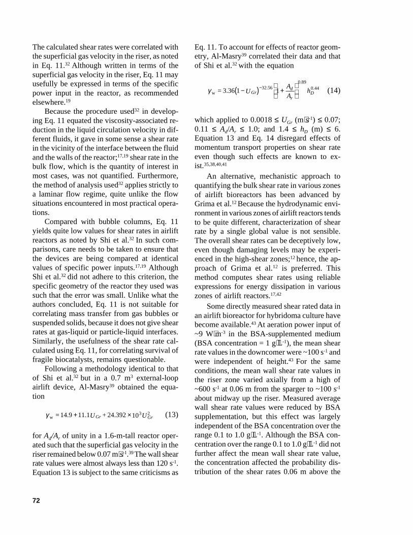
Mechanically stirred bioreactors are widelyused to culture animal cells.2,47-57 The localvelocity at a fixed position in a stirred bioreactorfluctuates around a mean value, hence the shearrate fluctuates. In the discharge streams of aRushton turbine (Figure 3), the fluctuating com-ponent of the local velocity increases with therotational speed of the impeller. The magni-tude of fluctuations depends on the specificlocation in the tank, the type of impeller, theagitation speed, and the properties of the fluid.In tanks with radial flow impellers such asRushton turbines, the velocity fluctuations aregreatest near the impeller tip and decline rap-idly as one moves radially outward from thetip. Elsewhere in the vessel, the velocity fluc-tuations are reduced yet further. Because ofthese factors, several different characteristicshear rate values may be identified, including
FIGURE 3. Rushton turbine.
74
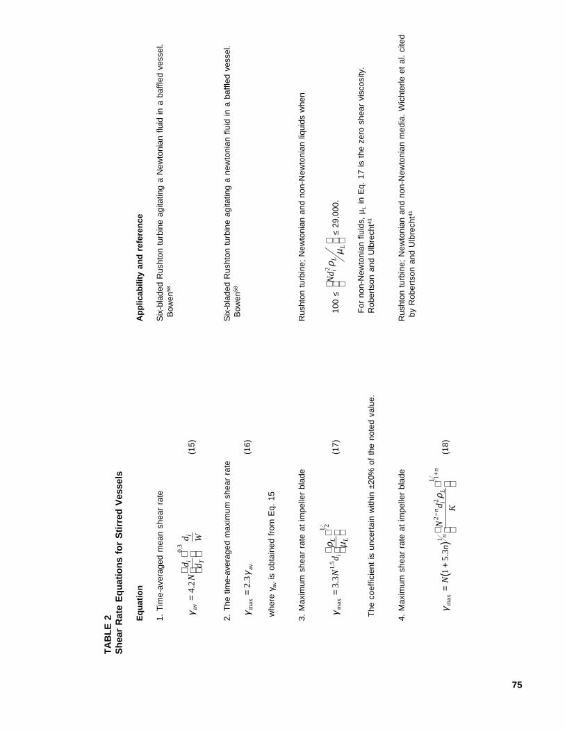
the time-averaged mean shear rate, the maxi-mum shear rate at the impeller, and the shearrate in the region swept by the impeller blades.Some of the expressions for estimating thevarious shear rates are summarized in Table 2.
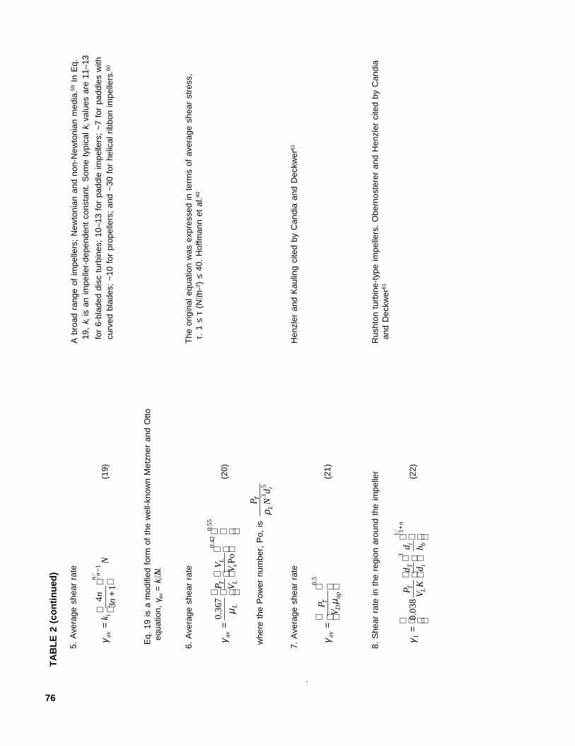
The available shear rate correlations arecompared in Figure 4 for water in a standardstirred tank60 agitated with a 0.1-m-diametersix-bladed Rushton turbine. For some context,the shear rate around a rising bubble may beapproximated as the ratio of the terminal risevelocity to the bubble diameter (or radius);hence,
γav =2U
dB
B
(23)
In air-water, under conditions typical of bubblecolumns and airlift reactors, the bubble risevelocity UB is about 0.2 m·s-1, and the bubblediameter dB is about 0.006 m. Thus, the inter-facial shear rate approximates to 67 s-1 if theinterface is nonmobile. Lower shear rates areexpected at circulating interfaces. Under someconditions, the turbulence field in a mechani-cally agitated vessel may be locally isotropic.When this happens, the equations in Table 2still provide useful estimates of maximum andthe average bulk shear rate values, but the shearrate associated with the fluid microeddies alsobecomes an important consideration as dis-cussed in Section II.E.
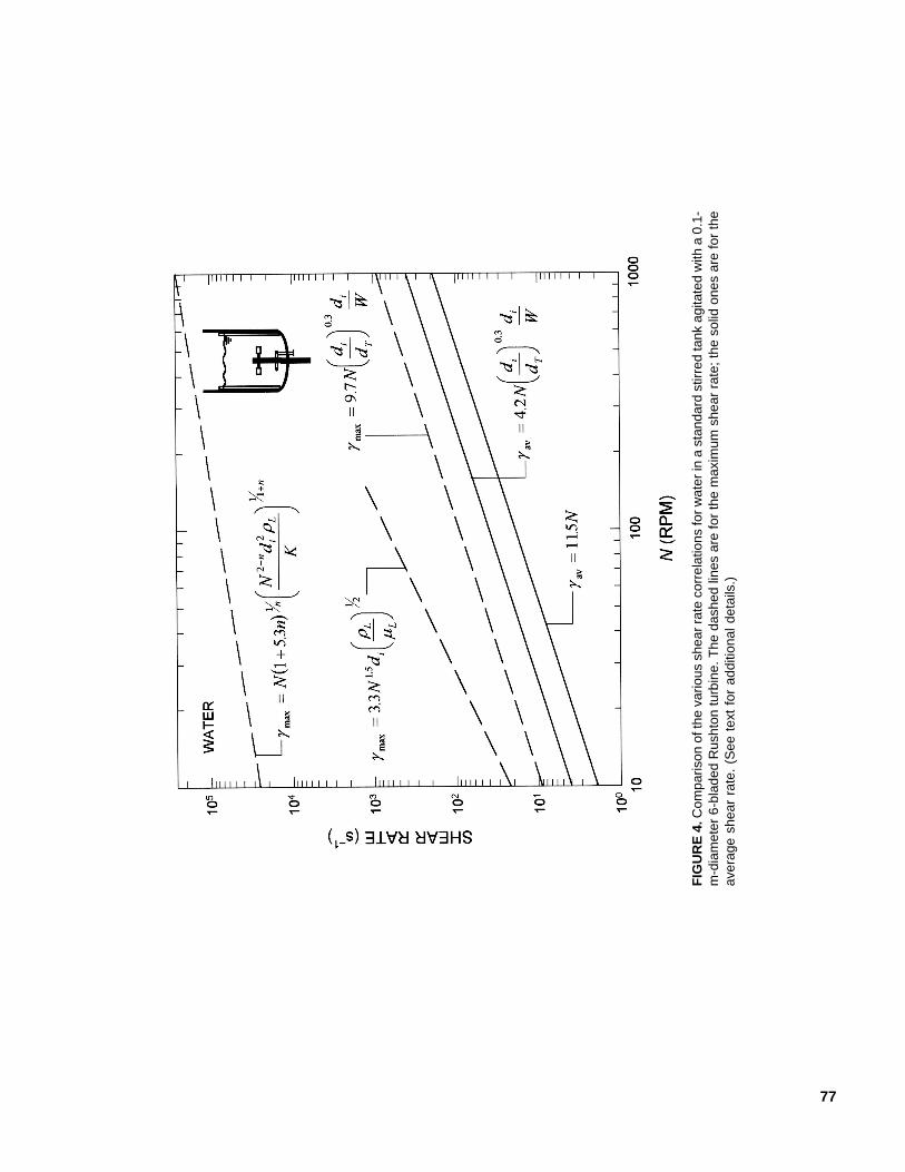
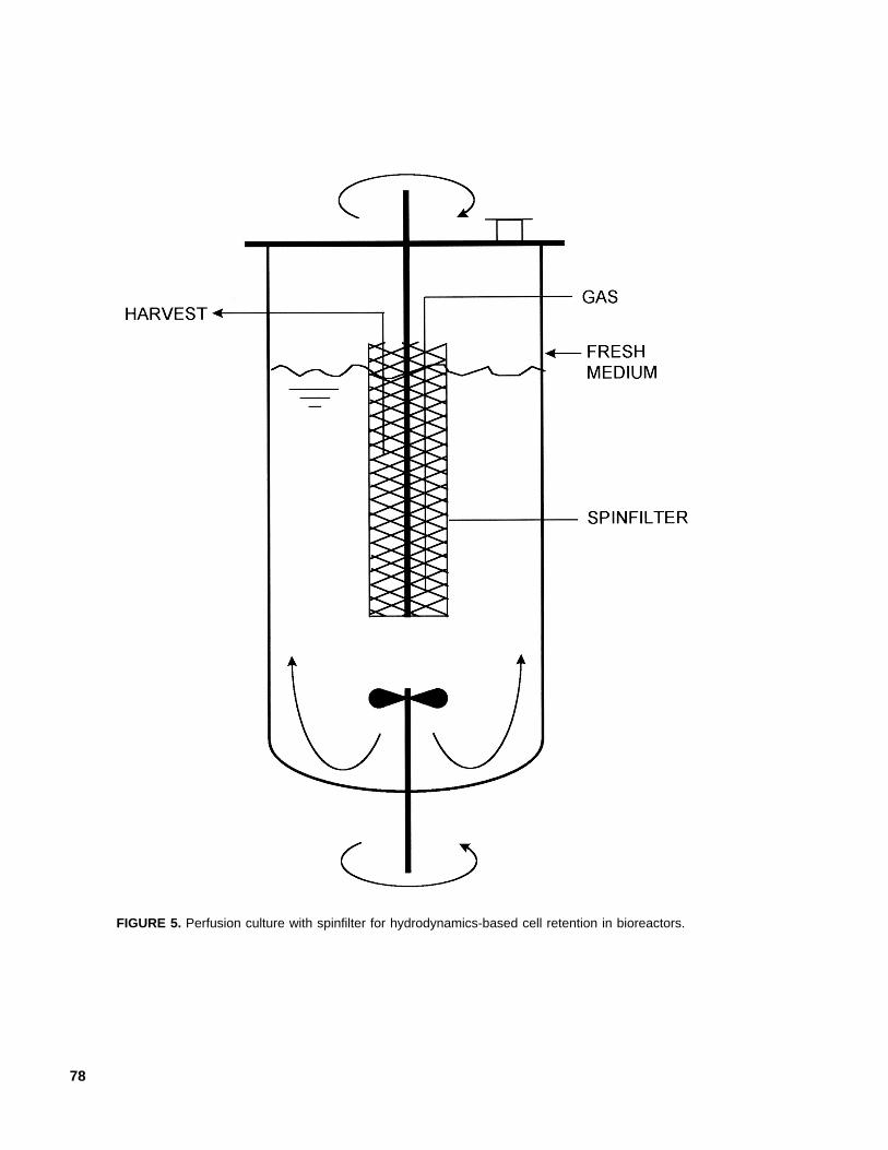
In perfusion culture of suspended animalcells, ‘spinfilters’ (Figure 5), or rotating cylin-ders made of wire mesh, are sometimes used toretain cells in the bioreactor. The wire screenopenings are significantly larger (e.g., 25 µm)than the cells, which are retained by a hydrody-namic mechanism requiring rapid rotation (e.g.,500 rpm) of the spinfilter. The cell-free spentmedium is withdrawn from the zone within therotating screen. Rotation of spinfilters does notgenerally damage animal cells.62 The cell-freezone within the rotating screen is sometimesused for aeration by sparging. Shear effectsmay become important in other designs of per-fusion devices.63
C. Pipework and Flow Channels
Flow in pipes and channels occurs com-monly during the transfer of culture betweenbioreactors, while harvesting, and during re-covery processes such as microfiltration andultrafiltration.21,22,47,64 Cell culture broths almostalways behave as Newtonian fluids. The brothviscosity is typically close to 0.75 × 10⁻³
Pa⋅s.52,65,66 In developed laminar flow of aNewtonian fluid through a straight tube of di-ameter d, the shear rate at the wall depends onthe mean flow velocity, UL, as follows:
γw = 8U
dL (24)
For a rectangular channel of height h, the maxi-mum or wall shear rate in developed laminarflow is
γw = 6U
hL (25)
where UL is again the mean flow velocity.The wall shear stress (i.e., the maximum
value) in a flow channel such as the riser of anairlift reactor is related to the pressure drop(∆P), the length L of channel, and the hydraulicdiameter;18 thus,
τ w = d
LP
4∆ (26)
Consequently, in turbulent flow, the wall shearstress is
τ ρw = 1
22C Uf L L (27)
where ρL is the liquid density and Cf is theFanning friction factor. The latter is relatedwith the Reynolds number as follows
CU d
fL L
L
=
−
0 07920 25
..
ρµ
(28)
75
TA
BL
E 2
Sh
ear
Rat
e E
qu
atio
ns
for
Sti
rred
Ves
sels
Eq
uat
ion
Ap
plic
abili
ty a
nd
ref
eren
ce
1. T
ime-
aver
aged
mea
n sh
ear
rate
Six
-bla
ded
Rus
hton
tur
bine
agi
tatin
g a
New
toni
an f
luid
in a
baf
fled
vess
el.
Bow
en58
γ av=
42
03
..
Nd d
d Wi T
i(1
5)
2. T
he t
ime-
aver
aged
max
imum
she
ar r
ate
Six
-bla
ded
Rus
hton
tur
bine
agi
tatin
g a
new
toni
an f
luid
in a
baf
fled
vess
el.
Bow
en58
γγ
max
.=
23
av(1
6)
whe
re γ
av is
obt
aine
d fr
om E
q. 1
5
3. M
axim
um s
hear
rat
e at
impe
ller
blad
eR
usht
on t
urbi
ne;
New
toni
an a
nd n
on-N
ewto
nian
liqu
ids
whe
n
γρ µ
max
..
=
3
31
5
1 2
Nd i
L L
(17)
100 ≤
Nd i
LL
2ρ
µ
≤
29,0
00.
For
non
-New
toni
an f
luid
s, µ
L in
Eq.
17
is t
he z
ero
shea
r vi
scos
ity.
The
coe
ffici
ent
is u
ncer
tain
with
in ±
20%
of
the
note
d va
lue.
Rob
erts
on a
nd U
lbre
cht41
4. M
axim
um s
hear
rat
e at
impe
ller
blad
eR
usht
on t
urbi
ne;
New
toni
an a
nd n
on-N
ewto
nian
med
ia.
Wic
hter
le e
t al
. ci
ted
by R
ober
tson
and
Ulb
rech
t41
γρ
max
.=
+(
)
−
+N
nN
d Kn
ni
Ln
15
31
22
1 1
(18)
76
5. A
vera
ge s
hear
rat
eA
bro
ad r
ange
of
impe
llers
; N
ewto
nian
and
non
-New
toni
an m
edia
.59 I
n E
q.19
, k i
is a
n im
pelle
r-de
pend
ent
cons
tant
. S
ome
typi
cal k
i val
ues
are
11–1
3
γ av=
+
−
kn
nN
i
nn
4
31
1(1
9)fo
r 6-
blad
ed d
isc
turb
ines
; 10
–13
for
padd
le im
pelle
rs;
~7
for
padd
les
with
curv
ed b
lade
s; ~
10 f
or p
rope
llers
; an
d ~
30 f
or h
elic
al r
ibbo
n im
pelle
rs.60
Eq.
19
is a
mod
ified
for
m o
f th
e w
ell-k
now
n M
etzn
er a
nd O
ttoeq
uatio
n, γ
av=
k i⋅N
.
6. A
vera
ge s
hear
rat
eT
he o
rigin
al e
quat
ion
was
exp
ress
ed in
ter
ms
of a
vera
ge s
hear
str
ess,
τ. 1
≤ τ
(N⋅m
-2 ) ≤
40.
Hof
fman
n et
al.40
γµ
avP
o=
0
367
042
055
..
.
L
T L
L
s
P V
V V(2
0)
whe
re t
he P
ower
num
ber,
Po,
is
P Nd
T
Li
ρ3
5
7. A
vera
ge s
hear
rat
eH
enzl
er a
nd K
aulin
g ci
ted
by C
andi
a an
d D
eckw
er61
.
γµ
av=
P
VT
Da
p
05.
(21)
8. S
hear
rat
e in
the
reg
ion
arou
nd t
he im
pelle
rR
usht
on t
urbi
ne-t
ype
impe
llers
. O
bern
oste
rer
and
Hen
zler
cite
d by
Can
dia
and
Dec
kwer
61
γ I=
+
00
38
31 1
.P V
K
d d
d hT L
T i
i b
n
(22)
TA
BL
E 2
(co
nti
nu
ed)
77
FIG
UR
E 4
. Com
paris
on o
f the
var
ious
she
ar r
ate
corr
elat
ions
for
wat
er in
a s
tand
ard
stirr
ed ta
nk a
gita
ted
with
a 0
.1-
m-d
iam
eter
6-b
lade
d R
usht
on tu
rbin
e. T
he d
ashe
d lin
es a
re fo
r th
e m
axim
um s
hear
rat
e; th
e so
lid o
nes
are
for
the
aver
age
shea
r ra
te.
(See
tex
t fo
r ad
ditio
nal d
etai
ls.)
78
FIGURE 5. Perfusion culture with spinfilter for hydrodynamics-based cell retention in bioreactors.
79
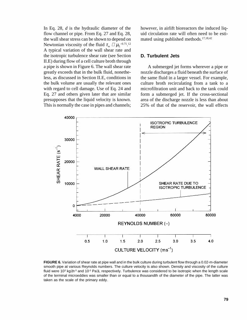
In Eq. 28, d is the hydraulic diameter of theflow channel or pipe. From Eq. 27 and Eq. 28,the wall shear stress can be shown to depend onNewtonian viscosity of the fluid τw ∝ µL
–0.75.12
A typical variation of the wall shear rate andthe isotropic turbulence shear rate (see SectionII.E) during flow of a cell culture broth througha pipe is shown in Figure 6. The wall shear rategreatly exceeds that in the bulk fluid, nonethe-less, as discussed in Section II.E, conditions inthe bulk volume are usually the relevant oneswith regard to cell damage. Use of Eq. 24 andEq. 27 and others given later that are similarpresupposes that the liquid velocity is known.This is normally the case in pipes and channels;
however, in airlift bioreactors the induced liq-uid circulation rate will often need to be esti-mated using published methods.17,18,42
D. Turbulent Jets
A submerged jet forms wherever a pipe ornozzle discharges a fluid beneath the surface ofthe same fluid in a larger vessel. For example,culture broth recirculating from a tank to amicrofiltration unit and back to the tank couldform a submerged jet. If the cross-sectionalarea of the discharge nozzle is less than about25% of that of the reservoir, the wall effects
FIGURE 6. Variation of shear rate at pipe wall and in the bulk culture during turbulent flow through a 0.02-m-diametersmooth pipe at various Reynolds numbers. The culture velocity is also shown. Density and viscosity of the culturefluid were 103 kg⋅m-3 and 10-3 Pa⋅s, respectively. Turbulence was considered to be isotropic when the length scaleof the terminal microeddies was smaller than or equal to a thousandth of the diameter of the pipe. The latter wastaken as the scale of the primary eddy.
80
can be neglected and the jet is said to be ‘free.’A jet is turbulent when the Reynolds number atthe orifice exceeds about 3000. In a stable sub-merged turbulent jet, the maximum shear stressoccurs in the direction of discharge, six to sevennozzle diameters downstream from the orifice.This shear stress is given as
τ ρmax .J = 0 018 2L ou (29)
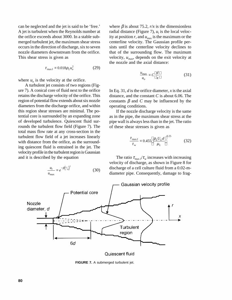
where uo is the velocity at the orifice.A turbulent jet consists of two regions (Fig-
ure 7). A conical core of fluid next to the orificeretains the discharge velocity of the orifice. Thisregion of potential flow extends about six nozzlediameters from the discharge orifice, and withinthis region shear stresses are minimal. The po-tential core is surrounded by an expanding zoneof developed turbulence. Quiescent fluid sur-rounds the turbulent flow field (Figure 7). Thetotal mass flow rate at any cross-section in theturbulent flow field of a jet increases linearlywith distance from the orifice, as the surround-ing quiescent fluid is entrained in the jet. Thevelocity profile in the turbulent region is Gaussianand it is described by the equation
u
uel
rx
max
=− ( )β
2
(30)
where β is about 75.2, r/x is the dimensionlessradial distance (Figure 7), ul is the local veloc-ity at position r, and umax is the maximum or thecenterline velocity. The Gaussian profile per-sists until the centerline velocity declines tothat of the surrounding flow. The maximumvelocity, umax, depends on the exit velocity atthe nozzle and the axial distance:
u
uC
d
xo
max =
(31)
In Eq. 31, d is the orifice diameter, x is the axialdistance, and the constant C is about 6.06. Theconstants β and C may be influenced by theoperating conditions.
If the nozzle discharge velocity is the sameas in the pipe, the maximum shear stress at thepipe wall is always less than in the jet. The ratioof these shear stresses is given as
ττ
ρµ
maxJ
w
=
0 4550 25
..
L L
L
U d (32)
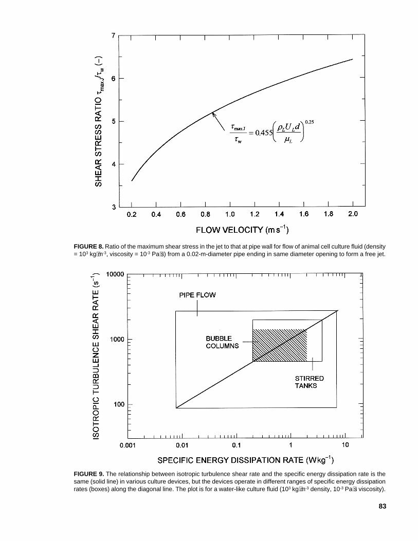
The ratio τmax J/τw increases with increasingvelocity of discharge, as shown in Figure 8 fordischarge of a cell culture fluid from a 0.02-m-diameter pipe. Consequently, damage to frag-
FIGURE 7. A submerged turbulent jet.
81
ile cells may occur during transfer operationssuch as inoculation of a bioreactor even thoughthe velocity in the transfer pipe may be rela-tively low. These effects can be avoided bydischarging the jet above the level of the re-ceiving fluid such that the liquid flows downthe vessel wall.
Energy dissipation rates in turbulent jetsare nonuniform. Dissipation is greatest near theaxis of the jet and declines radially outward,becoming negligible at dimensionless radialdistances (r/x) of greater than 0.2. In the fullydeveloped turbulent region, the radially aver-aged energy dissipation rate E declines withaxial location as follows:
Ed u
xo=
η 4 3
3
/ (33)
where the constant η is about 50.67,68
E. Shear Phenomena in IsotropicTurbulence
A turbulence field in any process equip-ment is said to be isotropic when the size of theprimary eddies generated by the turbulencecausing mechanism is a thousandfold or morecompared with the size of the energy dissipat-ing microeddies. Depending on the situation,the length scale of the primary eddies may beapproximated as the width of the impeller bladeor the diameter of the impeller in a stirred tank.In bubble columns and airlift bioreactors, thelength scale of primary eddies is approximatedas the diameter of the column (or the risertube), or the diameter of the bubble issuingfrom the gas sparger;5,18 the latter approach ispreferred because a rising bubble is the pri-mary source of turbulence in most gas-agitatedbioreactors.
Shear stress, shear rate, the dimensions ofmicroeddies, and other characteristics of floware ultimately determined by the energy inputand dissipation rates in the fluid. The local shearrate in the vicinity of an eddy in an isotropically
turbulent field may be estimated as the ratio ofthe velocity and the length of the eddy; hence,
γ µ
ρiL
L
u= =l l2 (34)
where ρL and µL are, respectively, the densityand the viscosity of the fluid. The mean length,l, and the velocity, u, of the microeddies arerelated with the specific energy dissipation rateE in the turbulence field; thus,
l =
−µρ
L
L
E
34 1
4 (35)
and
uEL
L
=
µρ
14
(36)
Generally, all the energy imparted to a fluid isdissipated in microeddies, and E equals the rateof energy input. Equations 34 to 36 apply whenlocal isotropic turbulence prevails.
For single-phase pipe flow, the specificenergy dissipation rate is
EU P
LL
L
= ∆ρ
(37)
where ∆P is the pressure drop over the tubelength L, and UL is the mean flow velocity. Thepressure drop may be computed using the ear-lier noted Eqs. 26 to 28. The energy dissipationrate in bubble columns and airlift vessels is afunction of the superficial aeration velocity;17,18
thus
E gUG= (bubble columns) (38)
and
E gU
A
A
Gr
d
r
=+1
(airlift bioreactors) (39)
82
Methods for calculating the specific energydissipation rate in stirred vessels have beendiscussed elsewhere.60,69 The mean energy dis-sipation rate in an unaerated vessel is given as
EN di= Po
VL
3 5
(40)
where Po is the power number, di is the diam-eter of the impeller, and N is the rotation speed(s-1). In developed turbulent flow in stirredvessels, that is, when the impeller Reynoldsnumber (Ndi L L
2 ρ µ ) exceeds 104, the power
number is generally constant for a given typeof impeller and tank geometry. The constantPower number values are noted in Table 3 forsome common types of impellers in baffledstirred tanks. The energy dissipation rate in thepresence of aeration is generally less than inthe equivalent ungassed state. The extent ofreduction depends on the aeration rate used. Intypically aerated conditions in microbial cul-ture, the energy dissipated is generally 50 to60% of the nonsparged case; however, in ani-mal cell culture the aeration rates are so smallthat power number is barely affected by aera-tion.
The local energy dissipation varies greatlyfrom the mean value in a stirred tank. Themaximum energy dissipation occurs in the vi-cinity of the impellers and this maximum valuecan be calculated using the equation
E N di= Po 3 2 (41)
Equation 41 assumes that dissipation oc-curs in the volume around the impeller, butit disregards flow through that volume. Ifthe volume flowing through the impellerzone in 1 s is taken into account, the maxi-mum specific energy dissipation will re-duce by a factor that depends on the rota-tional speed and the geometry of theimpeller.
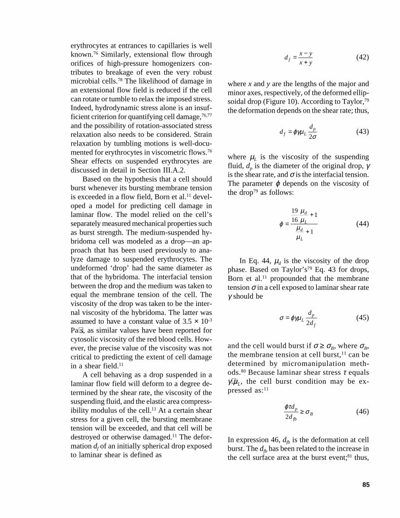
As noted in Figure 9, the same relationshipexists between the isotropic turbulence shearrate and the specific energy dissipation rate invarious culture devices; however, because thedifferent devices operate in different ranges ofspecific energy dissipation rates, the shear ratesexperienced by cells are different under typi-cally used culture conditions. Generally, if abiocatalyst particle is much smaller than thecalculated length, l, of the microeddies, theparticle is simply carried around by the fluideddy, without experiencing any disruptive force.In contrast, a particle that is larger than thelength scale of the eddy will experience pres-sure differentials on its surface. The resultingforce may kill or rupture the cell. Turbulencewithin the fluid is only one factor contributingto cell damage in a bioreactor. Other damage-causing phenomena are interparticle collisions;collisions with walls, other stationary surfaces,and the impeller; shear forces associated withbubble rupture at the surface of the fluid;3-6,8
phenomena linked with bubble coalescence,breakup, and rise;70,71 and bubble formation atthe gas sparger. Some of these damaging phe-nomena are discussed in other sections of this
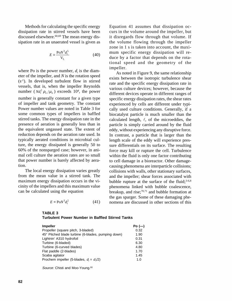
TABLE 3Turbulent Power Number in Baffled Stirred Tanks
Impeller Po (—)Propeller (square pitch, 3-bladed) 0.3245° Pitched blade turbine (6-blades, pumping down) 1.90Lightnin’ A310 hydrofoil 0.31Turbine (6-bladed) 6.30Turbine (6-curved blades) 4.80Flat paddle (2-blades) 1.70Scaba agitator 1.45Prochem impeller (5-blades, di = dT/2) 1.0
Source: Chisti and Moo-Young.60
83
FIGURE 8. Ratio of the maximum shear stress in the jet to that at pipe wall for flow of animal cell culture fluid (density= 103 kg⋅m-3, viscosity = 10-3 Pa⋅s) from a 0.02-m-diameter pipe ending in same diameter opening to form a free jet.
FIGURE 9. The relationship between isotropic turbulence shear rate and the specific energy dissipation rate is thesame (solid line) in various culture devices, but the devices operate in different ranges of specific energy dissipationrates (boxes) along the diagonal line. The plot is for a water-like culture fluid (103 kg⋅m-3 density, 10-3 Pa⋅s viscosity).

84
article. Other approaches to calculating shearstresses in turbulent flow are discussed byCherry and Kwon.72
Summarizing, several possible shear ratevalues may be calculated for a given situationin a bioprocess device. Not every calculatedvalue is appropriate or relevant to the problemat hand. For pneumatically agitated bioreactors,when the turbulence characteristics in the bulkfluid are the relevant ones, the preferred ap-proach is to use Eq. 34 for shear rate in thevicinity of eddies. The same applies to me-chanically stirred tanks. In flow systems suchas pipes and channels, the shear rate at the wallis always greater than in bulk flow (Figure 6);nevertheless, the shear rate in the bulk fluid isgenerally the more relevant with regards to celldamage. There are two reasons for this: (1)because of hydrodynamic forces cells typicallymove away from the walls; and (2) a relativelyhigh shear rate in laminar flow of the boundarylayer adjacent to walls is less damaging than asimilar shear rate in turbulent flow away fromwalls.5 In some cases, the relevant shear ratemay be that at the interface of a rising bubbleunless turbulence is so intense that bubbles donot rise freely. Other situations would be con-trolled by the bubble rupture events,3,4,6,8,73 asdiscussed later. In yet other cases, the fluideddy shear rate and the maximum shear rate atthe impeller will need to be taken into account.Factors such as the frequency of passage of asensitive biocatalyst through a high shear re-gion may need to be considered for cyclic flowssuch as occur in stirred tanks, airlift devices,and recycle loops.
F. Effects of Suspended Particles onTurbulence
Suspended particles such as cells andmicrocarriers themselves modulate turbulence.These effects are complex74 and depend on theratio of the particle diameter dp and the lengthof the energy-containing eddy, le. Small par-ticles follow the fluid flow, and some of the
turbulent energy is transformed into the par-ticles’ kinetic energy.75 When dp/le is smallerthan 0.1, the particle dissipates energy and tur-bulence is dampened. Larger particles (dp/le >0.1) enhance small-scale turbulence throughwakes induced by their relative velocity withrespect to the fluid.75 How much turbulence isenhanced or dampened depends on the system,not on the magnitude of dp/le. When the con-centration of solids in suspension exceeds 20 to30% (by vol), the dominant mechanism affect-ing the flow is particle-particle interactions andnot particle-fluid interactions.75 In microcarrierculture of animal cells, the volume fraction ofsolids is typically less than 10%, but higherconcentrations may occur in processes such asthe expanded bed chromatography of the wholebroth.20
III. SHEAR EFFECTS ON CELLS
A. Suspended Cells
1. Hybridomas and Suspension-Adapted Cells
Freely suspended animal cells in bubble-free bioreactors are not damaged by mechani-cal agitation even at intensities much greaterthan the ones used in typical processing. Ex-ceptions occur in extensional or elongationalflow in certain high-shear devices even whenthe flow is laminar.76,77 Extensional orelongational flow is produced whenever thecross-sectional area of the flow channel re-duces (e.g., at an orifice on the wall of a tankor at the entrance of a capillary connected to alarger reservoir). The fluid elements undergo-ing extensional flow stretch and thin. Suspendedparticles also experience elongational forces inthe direction of flow and compression perpen-dicular to the flow streamlines. Drops subjectedto extension flow can rupture. Although no cellis a homogeneous fluid, suspended animal cellssuch as granulocytes and hybridomas behavesimilar to drops in a shear field. Rupture of
85
erythrocytes at entrances to capillaries is wellknown.76 Similarly, extensional flow throughorifices of high-pressure homogenizers con-tributes to breakage of even the very robustmicrobial cells.78 The likelihood of damage inan extensional flow field is reduced if the cellcan rotate or tumble to relax the imposed stress.Indeed, hydrodynamic stress alone is an insuf-ficient criterion for quantifying cell damage,76,77
and the possibility of rotation-associated stressrelaxation also needs to be considered. Strainrelaxation by tumbling motions is well-docu-mented for erythrocytes in viscometric flows.76
Shear effects on suspended erythrocytes arediscussed in detail in Section III.A.2.
Based on the hypothesis that a cell shouldburst whenever its bursting membrane tensionis exceeded in a flow field, Born et al.11 devel-oped a model for predicting cell damage inlaminar flow. The model relied on the cell’sseparately measured mechanical properties suchas burst strength. The medium-suspended hy-bridoma cell was modeled as a drop—an ap-proach that has been used previously to ana-lyze damage to suspended erythrocytes. Theundeformed ‘drop’ had the same diameter asthat of the hybridoma. The interfacial tensionbetween the drop and the medium was taken toequal the membrane tension of the cell. Theviscosity of the drop was taken to be the inter-nal viscosity of the hybridoma. The latter wasassumed to have a constant value of 3.5 × 10⁻³
Pa⋅s, as similar values have been reported forcytosolic viscosity of the red blood cells. How-ever, the precise value of the viscosity was notcritical to predicting the extent of cell damagein a shear field.11
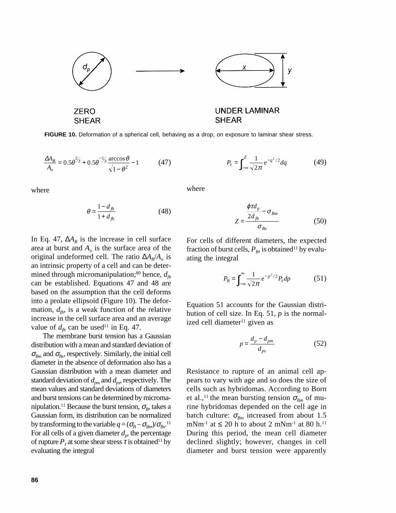
A cell behaving as a drop suspended in alaminar flow field will deform to a degree de-termined by the shear rate, the viscosity of thesuspending fluid, and the elastic area compress-ibility modulus of the cell.11 At a certain shearstress for a given cell, the bursting membranetension will be exceeded, and that cell will bedestroyed or otherwise damaged.11 The defor-mation df of an initially spherical drop exposedto laminar shear is defined as
dx y
x yf =−+
(42)
where x and y are the lengths of the major andminor axes, respectively, of the deformed ellip-soidal drop (Figure 10). According to Taylor,79
the deformation depends on the shear rate; thus,
dd
f Lp=ϕγµσ2
(43)
where µL is the viscosity of the suspendingfluid, dp is the diameter of the original drop, γis the shear rate, and σ is the interfacial tension.The parameter ϕ depends on the viscosity ofthe drop79 as follows:
ϕ
µµµµ
=+
+
19
161
1
d
L
d
L
(44)
In Eq. 44, µd is the viscosity of the dropphase. Based on Taylor’s79 Eq. 43 for drops,Born et al.11 propounded that the membranetension σ in a cell exposed to laminar shear rateγ should be
σ ϕγµ= Lp
f
d
d2(45)
and the cell would burst if σ ≥ σB, where σB,the membrane tension at cell burst,11 can bedetermined by micromanipulation meth-ods.80 Because laminar shear stress τ equalsγ⋅µL, the cell burst condition may be ex-pressed as:11
ϕτσ
d
dp
fbB2
≥ (46)
In expression 46, dfb is the deformation at cellburst. The dfb has been related to the increase inthe cell surface area at the burst event;81 thus,
86
∆A
AB
o
= +−
−−
0 5 0 51
12
313
2. .
arccosθ θ θ
θ(47)
where
θ =−+
1
1
d
dfb
fb
(48)
In Eq. 47, ∆AB is the increase in cell surfacearea at burst and Ao is the surface area of theoriginal undeformed cell. The ratio ∆AB/Ao isan intrinsic property of a cell and can be deter-mined through micromanipulation;80 hence, dfb
can be established. Equations 47 and 48 arebased on the assumption that the cell deformsinto a prolate ellipsoid (Figure 10). The defor-mation, dfb, is a weak function of the relativeincrease in the cell surface area and an averagevalue of dfb can be used11 in Eq. 47.
The membrane burst tension has a Gaussiandistribution with a mean and standard deviation ofσBm and σBs, respectively. Similarly, the initial celldiameter in the absence of deformation also has aGaussian distribution with a mean diameter andstandard deviation of dpm and dps, respectively. Themean values and standard deviations of diametersand burst tensions can be determined by microma-nipulation.11 Because the burst tension, σB, takes aGaussian form, its distribution can be normalizedby transforming to the variable q = (σB – σBm)/σBs.11
For all cells of a given diameter dp, the percentageof rupture Pτ at some shear stress τ is obtained11 byevaluating the integral
P e dqqZ
τ π= −
−∞∫1
2
2 2/ (49)
where
Z
d
dp
fbBm
Bs
=−
ϕτσ
σ2
(50)
For cells of different diameters, the expectedfraction of burst cells, PB, is obtained11 by evalu-ating the integral
P e P dpBp= −
−∞
∞
∫ 1
2
2 2
π τ/ (51)
Equation 51 accounts for the Gaussian distri-bution of cell size. In Eq. 51, p is the normal-ized cell diameter11 given as
pd d
dp pm
ps
=−
(52)
Resistance to rupture of an animal cell ap-pears to vary with age and so does the size ofcells such as hybridomas. According to Bornet al.,11 the mean bursting tension σBm of mu-rine hybridomas depended on the cell age inbatch culture: σBm increased from about 1.5mNm-1 at ≤ 20 h to about 2 mNm-1 at 80 h.11
During this period, the mean cell diameterdeclined slightly; however, changes in celldiameter and burst tension were apparently
FIGURE 10. Deformation of a spherical cell, behaving as a drop, on exposure to laminar shear stress.
87
unrelated.80 Through the culture period, themean value of the ∆AB/Ao ratio was about 2.11
Born et al.11 noted that the percent disruptionpredicted by the model compared well withthe experimental data for various levels ofapplied laminar shear stress in a cone-and-plate viscometer.
The cell damage model of Born et al.11 im-plies that a cell exposed a certain laminar shearstress is either disrupted or it remains unaffected;thus, cell loss is predicted to be independent ofthe duration of exposure. In theory, the modelshould allow a prediction of the cell survivalbehavior from mechanical property data mea-sured by micromanipulation. Born et al.11 pro-vide some evidence in support of their model,but its broader applicability remains question-able in view of the many nonconforming obser-vations.82-84 As pointed out in Section III.B.2, acell will experience debilitating damage andeffective loss of function long before damagingforces reach the threshold of physical destruc-tion. Consequently, unless there is a direct andidentifiable relationship between loss of func-tion prior to physical rupture and the rupturethreshold conditions, the practical utility of theapproach propounded is limited at best. Also,cells sheared in a cone-and-plate device experi-ence different levels of shear stress dependingon how far they are from the apex of the cone.Indeed, cells nearer the apex have been observedto undergo severe deformations, while those nearthe edge of the cone may be little affected.76
For a hybridoma line, Born et al.11 reportedthat exposure to laminar shear stress (208 N⋅m-2)in unaerated flow in a cone-and-plate viscom-eter led to substantial loss in cell count andviability within 20 min. At a constant 180-sexposure, increasing shear stress over 100 to350 N⋅m-2 linearly enhanced cell disruption,with >90% of the cells being destroyed at 350N⋅m-2 stress level.11 Shear stress levels of theorder of 100 to 300 N⋅m-2 do occur duringbubble rupture at the surface of a bioreactor.85
In view of the reported observations,11 simi-larly high values of shear stress also damagehybridomas in unaerated laminar flow.
Shear stress related damage to a mouse-mouse hybridoma was examined by Abu-Reeshand Kargi82 under laminar and turbulent condi-tions in a coaxial cylinder Searle viscometer.Cells were exposed to 5 to 100 N⋅m-2 shearstress levels for 0.5 to 3.0 h. At a given shearstress and exposure time, turbulent shear wasmuch more damaging than laminar shear82 asalso reported in the past83 for protozoa andplant cells.86 Under turbulent conditions, dam-age occurred when shear stress exceeded 5 N⋅m-2.82
Respiratory activity of the cells was damagedearlier than the cell membrane, thus implyingtransmission of the stress signal to the interiorof the cell. Cell damage followed first-orderkinetics both in laminar and turbulent environ-ments. For turbulent shear stress levels of 5 to30 N⋅m-2, the death rate constant (kd) increasedexponentially with increasing stress level; thekd values varied over 0.1 to 1.0 h-1. In coaxialcylinder viscometers with a gap width w and aninner cylinder of diameter di rotating at periph-eral speed UT, the laminar-turbulent flow tran-sition is defined by Taylor number (Ta) that isgiven as
Ta=
ρµ
L T
L i
U w w
d
20 5.
(53)
The flow is laminar when Ta < 41.3. Lami-nar flow with Taylor vortices occurs when 41.3< Ta < 400. Fully developed turbulent flowobtains when Taylor number exceeds 400. Abu-Reesh and Kargi82 varied the rotational speedof the inner cylinder and the viscosity of thesuspending fluid to attain different values ofTaylor number. The viscosity was varied byadding 2000 kDa dextran.
For hybridoma cells separately grown incontinuous culture at various specific growthrates, Petersen et al.87 concluded that shear sen-sitivity in a Couette viscometer at a constantshear rate of 5000 s-1 was independent of growthrate or of the metabolic state for cells fromexponential growth phase. The same cell linewas more sensitive to viscometric shear during
88
lag and stationary phases. This behavior con-trasts with that of microbial cells that generallybecome increasingly shear sensitive as the spe-cific growth rate increases.78 The latter behav-ior is associated with poorer development ofcell walls in faster growing cells, but animalcells do not have walls and this possibly ex-plains the different behavior.
For a suspended mouse myeloma line inturbulent capillary flow, McQueen et al.13 noteda threshold average wall shear stress value of180 N⋅m-2 when lysis first commenced. Al-though the flow caused lysis, it had no effect onviability,13 suggesting that cells at variousgrowth stages were equally affected. The sud-den flow contraction at the entrance to the cap-illary may have contributed to cell lysis, but theresidence time in the capillary also had an ef-fect at otherwise constant average wall shearstress level. The rate of lysis was first-order incell number. Above the threshold shear stressvalue, the specific lysis rate increased withincreasing level of shear stress.13 The growthrate and the DNA synthesis rate of the cellsexposed to the shearing environment were un-affected when the surviving cells were returnedto a normal quiescent growth environment.13 Inother studies cited by McQueen et al.,13 theshear stress threshold for damage has been re-ported as 0.87 N⋅m-2 for a mouse hybridomaand 1.5 N⋅m-2 for insect cells. Higher shearsensitivity of another mouse cell line relative toa human carcinoma has been reported.10
For human cervical carcinoma HeLa S3and mouse abdominal fibroblast L929,Augenstein et al.10 observed lysis of suspendedcells in turbulent flow through stainless steelcapillaries. Cell death could be correlated withthe average wall shear stress level or the powerdissipation within the capillaries. The L929line was more sensitive than the human cell.Control experiments showed that the positivedisplacement pumps used to circulate the cellsthrough capillaries contributed little to cell ly-sis.10 Average wall shear stress levels of (0.1-2.0) × 103 N⋅m-2 were sufficient to induce cellinactivation for the two lines. According to
Shiragami,15 the mean shear stress acting oncells suspended in capillary flow is the shearstress at the capillary walls, so long as the ratioof the cell’s diameter to that of the capillary is<0.08.
For a hybridoma examined by Shiragami,88
the specific rate of monoclonal antibody pro-duction in a surface aerated spinner flask de-pended on the agitation speed. In a 250-mLspinner vessel an agitation rate of ~180 rpmgave the highest specific antibody productionrate. The specific productivities were reducedat higher or lower values of agitation speed.The increased antibody production with increas-ing agitation was associated supposedly withenhanced secretion in a more turbulent envi-ronment.88 Oxygen transfer effects may havebetter explained the observations (see Ref. 66),but no data were reported on this aspect.
Damage to murine hybridomas was ob-served by Jan et al.62 in stirred tanks equippedwith marine impellers agitated at sufficientlyhigh speeds that vortexing occurred and gasentrained into the medium. Even at these highspeeds, damage could be prevented by bafflingthe tank, which suppressed vortex formation.Usually though, vortexing is not a problem inlarge-scale cell culture. Unbaffled, marine im-peller-stirred tanks were used successfully byChisti47 in industrial culture of several hybri-doma lines. Effects of agitation on hybridomaculture in the absence of sparging or surfaceentrainment were further examined by Smithand Greenfield.55 Culture growth was unaffectedby agitation intensity (100 or 600 rpm) in theRPMI medium supplemented with fetal bovineserum (10% vol/vol). However, in PFHM IImedium supplemented with either Pluronic F68,fetal bovine serum, or bovine serum albumin,and agitated at 600 rpm (impeller tip speed =1.6 m⋅s-1, power input = 1 kW⋅m-3) the resultswere different: the agitation intensity did notaffect the exponential growth rate, but oncegrowth had ceased, the decline phase was sub-stantially faster than in control experiments.55
Using steady-state continuous culture of ahybridoma in a surface aerated baffled vessel
89
stirred with a paddle impeller, Abu-Reesh andKargi89 showed that agitation tip speeds up to~0.7 m⋅s-1 did not damage cells in a mediumsupplemented with 15% (vol/vol) horse serum.At a lower serum concentration of 7.5%, im-peller tip speeds of ~0.5 m⋅s-1 damaged cellsand the specific death rate increased with in-creasing impeller tip speed. Whether any gasentrainment or vortexing occurred was not clear.In media with 7.5% serum, increasing dilutionrate over 0.02 to 0.50 h-1 reduced the viable cellconcentration at constant impeller tip speeds of0.21 m⋅s-1 and 0.52 m⋅s-1.89 The agitation-asso-ciated damage was first order in cell number.An insect cell line (S. frugiperda, Sf9) wasmore prone to damage. In unaerated stirredcultures, the specific growth rate declined no-ticeably as the tip speed of standard Rushtonturbine increased over 0.24 to 0.94 m⋅s-1 inparallel batch experiments.90 At 0.70 m⋅s-1 tipspeed in paired batch cultures, the growth ratewas slightly faster in a marine impeller stirredvessel than in one agitated with a standardRushton turbine.90
Elias et al.48 subjected quiescent environ-ment cultured human erythrocytic leukocytesto agitation (120 min) in 250-mL Bellco spin-ner flasks and characterized cell damage as afunction of agitation speed of the suspended42-mm-diameter magnetic bar agitator. The agi-tation tip speeds tested were 0.105, 0.21, and0.315 m⋅s-1. Relative to static T-flask culture,the viable cell count as measured by dye exclu-sion was only marginally reduced at 0.210 and0.315 m⋅s-1 tip speeds; however, the cells sub-jected to these agitation speeds (120 min) failedto proliferate on transfer to a quiescent envi-ronment.48 In contrast, cells that had not beenagitated, or agitated only at 0.105 m⋅s-1, grewnormally when transferred to a static environ-ment. The cells were cultured in RMPI 1640supplemented with 10% fetal bovine serum.Thus, in some cases at least, turbulence in theabsence of aeration does apparently damagecells even under typically used culture condi-tions, but the damage may go unnoticed be-cause of the limitations of the dye exclusion
methodology91 unless growth profiles are re-corded over a significant period. According toElias et al.,48 microscopic observations revealedsignificant damage to actin cytoskeletal net-work of cells exposed to 0.21 m⋅s-1 (120 min)impeller speed.
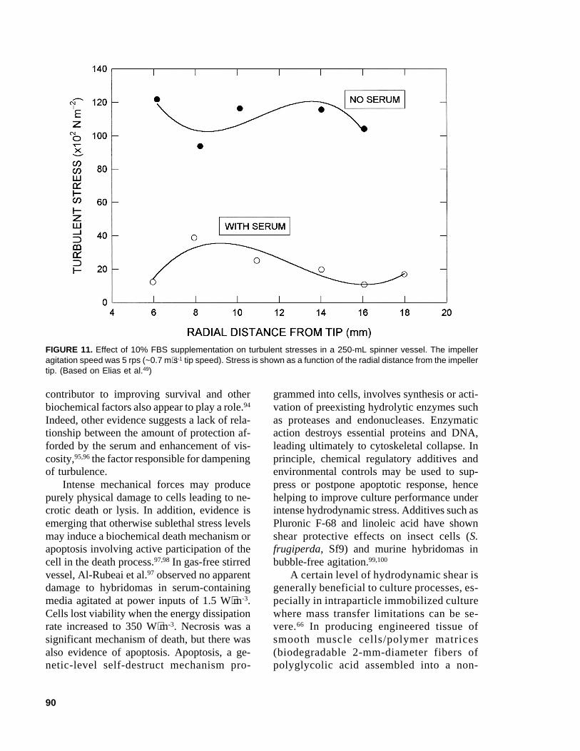
Cells grown in FBS-supplemented media,when exposed to a previously nondamagingagitation speed of 0.105 m⋅s-1 in the absence of10% FBS, failed to proliferate on transfer to acomplete medium.48 At a higher agitation speedof 0.21 m⋅s-1, supplementation with serum failedto protect cells. These observations were inter-preted in terms of the turbulence dampeningeffect of serum. For otherwise equivalent con-ditions, the addition of 10% FBS to RPMI1640 medium reduced turbulence as indicatedby reduced root mean square velocity fluctua-tions measured by laser doppler anemometry.48
Similarly, FBS supplementation reduced tur-bulent shear stresses in the fluid as shown inFigure 11.48 In another study, supplementationof the culture medium with BSA reduced theaverage wall shear stress in an airlift device.43
This effect was largely independent of the BSAconcentration over the range 0.1 to 1.0 g⋅L-1;however, BSA stimulated the hybridoma cellgrowth only at concentrations of 0.4 g⋅L-1 orgreater.43 (Note: 1 g⋅L-1 protein is equivalent toabout 2% (vol/vol) serum; therefore, 0.2 to2.0% serum may be sufficient to reduce turbu-lence in boundary layers next to a ridged sur-face.) Because growth stimulation did not oc-cur until a concentration of 0.4 g⋅L-1, whereasturbulence was dampened at a lower concen-tration, and the damaging effect was indepen-dent of concentration, the turbulence dampen-ing alone may not be a sufficient explanationfor the observed improved growth.
The precise nature of the protective effectof serum is not clear; however, in view of themeasurements,43,48 supplementation with suffi-cient serum clearly dampens turbulence andseveral authors have suggested this to be thesurvival enhancing mechanism of serum.51,92,93
Nevertheless, available data43 do not supportthe turbulence-dampening effect as the sole
90
contributor to improving survival and otherbiochemical factors also appear to play a role.94
Indeed, other evidence suggests a lack of rela-tionship between the amount of protection af-forded by the serum and enhancement of vis-cosity,95,96 the factor responsible for dampeningof turbulence.
Intense mechanical forces may producepurely physical damage to cells leading to ne-crotic death or lysis. In addition, evidence isemerging that otherwise sublethal stress levelsmay induce a biochemical death mechanism orapoptosis involving active participation of thecell in the death process.97,98 In gas-free stirredvessel, Al-Rubeai et al.97 observed no apparentdamage to hybridomas in serum-containingmedia agitated at power inputs of 1.5 W⋅m-3.Cells lost viability when the energy dissipationrate increased to 350 W⋅m-3. Necrosis was asignificant mechanism of death, but there wasalso evidence of apoptosis. Apoptosis, a ge-netic-level self-destruct mechanism pro-
grammed into cells, involves synthesis or acti-vation of preexisting hydrolytic enzymes suchas proteases and endonucleases. Enzymaticaction destroys essential proteins and DNA,leading ultimately to cytoskeletal collapse. Inprinciple, chemical regulatory additives andenvironmental controls may be used to sup-press or postpone apoptotic response, hencehelping to improve culture performance underintense hydrodynamic stress. Additives such asPluronic F-68 and linoleic acid have shownshear protective effects on insect cells (S.frugiperda, Sf9) and murine hybridomas inbubble-free agitation.99,100
A certain level of hydrodynamic shear isgenerally beneficial to culture processes, es-pecially in intraparticle immobilized culturewhere mass transfer limitations can be se-vere.66 In producing engineered tissue ofsmooth muscle cells/polymer matrices(biodegradable 2-mm-diameter fibers ofpolyglycolic acid assembled into a non-
FIGURE 11. Effect of 10% FBS supplementation on turbulent stresses in a 250-mL spinner vessel. The impelleragitation speed was 5 rps (~0.7 m⋅s-1 tip speed). Stress is shown as a function of the radial distance from the impellertip. (Based on Elias et al.49)

91
woven matrix), Kim et al.101 noted that seed-ing of the matrix under agitation led to sig-nificantly higher intramatrix cell densitiesthan when cells were seeded under staticconditions. Moreover, the higher cell densi-ties were attained more rapidly than thelower densities of static culture. In addition,the relative rates of synthesis of elastin andcollagen were significantly greater in seededmatrices cultured with agitation than in onesgrown statically.101 A lower possible supplyof oxygen or other nutrient may have re-duced the performance of static seedingmethodology. In view of the above-refer-enced studies and similar others, sufficientlyintense fluid mechanical forces other thanthose associated with aeration do affect cells.Table 4 provides a summary of the damag-ing thresholds of impeller tip speed andspecific power input for several kinds ofsuspended cells.
2. Blood Cells
Studies of shear effects on blood cells arerelevant in blood banking, processing, and trans-fusion. Also, shear susceptibility of cells hasimportant implications in the development ofcertain diseases and the design of biomedicaldevices such as artificial heart valves and heart-lung machines. Mammalian erythrocytes, orred blood cells, are the best studied of animalcells.5,76,102 Erythrocytes and leukocytes (whiteblood cells), being suspended cells in vivo, likelyexperience the kind of stresses encountered inbioreactors and various other industrial pro-cessing devices; hence, these cells may providea broad general insight into mechanical behav-ior of other cells of mammalian origin. Indeed,suitably chosen erythrocytes have been recom-mended as a standard cell for comparative as-sessment of the damaging potential of varioushydrodynamic environments.103 Because eryth-
TABLE 4Damaging Threshold Values of Impeller Tip Speed or Specific Power Input for SomeAnimal Cells
Stirred bioreactors Impeller tip speed (m ⋅⋅⋅⋅⋅s-1)
Human erythrocytic leukocytes (serumsupplemented) ≤0.21
S. frugiperda Sf9 (unaerated) <0.7Several hybridomas >1 (axial flow impellers)Hybridoma in stationary phase (no sparging) ~1.6 m⋅s-1 impeller tip speed
or power input of 1 kW⋅m-3
Hybridoma (serum-supplemented 15% vol/vol,surface aerated) ≥0.7
Hybridoma as above (serum-supplemented7.5%, surface aerated) ≤0.5
Hybridomas, serum-containing media, gas-freestirred vessel power inputs of <350 W⋅m-3
Airlift bioreactors Power input (W ⋅⋅⋅⋅⋅m-3)
Vero cells on microcarriers, medium with10% serum >2.6
Bubble columns Power input (W ⋅⋅⋅⋅⋅m-3)
Myeloma, serum-supplemented medium ~0.42
92
rocytes do not multiply in vitro, the effects ofcell damaging forces are not masked by growth-associated adaptation, changes in cell size, andstages of growth.
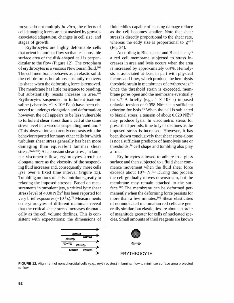
Erythrocytes are highly deformable cellsthat orient in laminar flow so that least possiblesurface area of the disk-shaped cell is perpen-dicular to the flow (Figure 12). The cytoplasmof erythrocytes is a viscous Newtonian fluid.102
The cell membrane behaves as an elastic solid:the cell deforms but almost instantly recoversits shape when the deforming force is removed.The membrane has little resistance to bending,but substantially resists increase in area.102
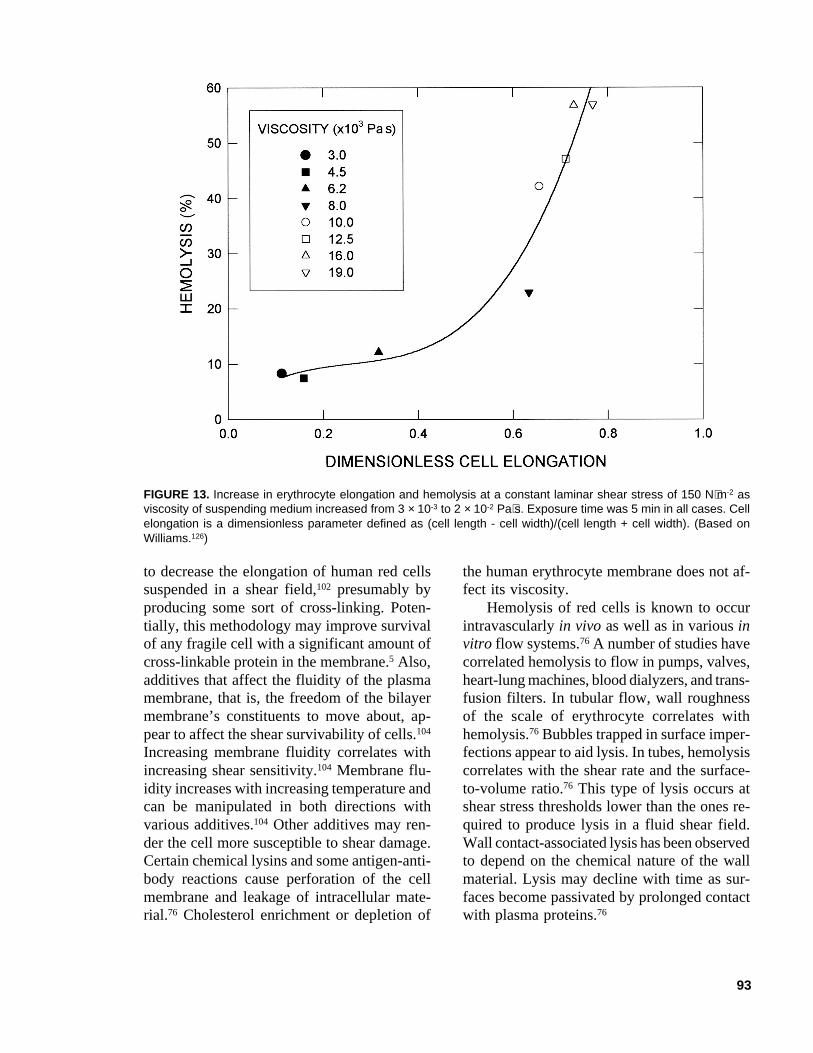
Erythrocytes suspended in turbulent isotonicsaline (viscosity ~1 × 10⁻³ Pa⋅s) have been ob-served to undergo elongation and deformation;however, the cell appears to be less vulnerableto turbulent shear stress than a cell at the samestress level in a viscous suspending medium.76
(This observation apparently contrasts with thebehavior reported for many other cells for whichturbulent shear stress generally has been moredamaging than equivalent laminar shearstress.82,83,86) At a constant shear stress, in lami-nar viscometric flow, erythrocytes stretch orelongate more as the viscosity of the suspend-ing fluid increases and, consequently, more cellslyse over a fixed time interval (Figure 13).Tumbling motions of cells contribute greatly torelaxing the imposed stresses. Based on mea-surements in turbulent jets, a critical lytic shearstress level of 4000 N⋅m-2 has been reported forvery brief exposures (~10-5 s).76 Measurementson erythrocytes of different mammals revealthat the critical shear stress increases dramati-cally as the cell volume declines. This is con-sistent with expectations: the dimensions of
fluid eddies capable of causing damage reduceas the cell becomes smaller. Note that shearstress is directly proportional to the shear rate,whereas the eddy size is proportional to γi
–0.5
(Eq. 34).According to Blackshear and Blackshear,76
a red cell membrane subjected to stress in-creases in area and lysis occurs when the areais increased by approximately 6.4%. Hemoly-sis is associated at least in part with physicalfactors and flow, which produce the hemolysisthreshold strain in membranes of erythrocytes.76
Once the threshold strain is exceeded, mem-brane pores open and the membrane eventuallytears.76 A briefly (e.g., 1 × 10⁻² s) imposeduniaxial tension of 0.058 N⋅m-1 is a sufficientcriterion for lysis.76 When the cell is subjectedto biaxial stress, a tension of about 0.029 N⋅m-1
may produce lysis. In viscometric stress forprescribed periods, time to lysis declines as theimposed stress is increased. However, it hasbeen shown conclusively that shear stress aloneis not a sufficient predictor of hemolysis rate orthresholds;76 cell shape and tumbling also playa role.
Erythrocytes allowed to adhere to a glasssurface and then subjected to a fluid shear com-mence movement when the fluid shear forceexceeds about 10-11 N.102 During this processthe cell gradually moves downstream, but themembrane may remain attached to the sur-face.102 The membrane can be deformed per-manently when the deforming force persists formore than a few minutes.102 Shear elasticitiesof nonnucleated mammalian red cells are gen-erally similar, but elasticities are about an orderof magnitude greater for cells of nucleated spe-cies. Small amounts of thiol reagents are known
FIGURE 12. Alignment of nonspheroidal cells (e.g., erythrocytes) in laminar flow to minimize surface area projectedto flow.
93
to decrease the elongation of human red cellssuspended in a shear field,102 presumably byproducing some sort of cross-linking. Poten-tially, this methodology may improve survivalof any fragile cell with a significant amount ofcross-linkable protein in the membrane.5 Also,additives that affect the fluidity of the plasmamembrane, that is, the freedom of the bilayermembrane’s constituents to move about, ap-pear to affect the shear survivability of cells.104
Increasing membrane fluidity correlates withincreasing shear sensitivity.104 Membrane flu-idity increases with increasing temperature andcan be manipulated in both directions withvarious additives.104 Other additives may ren-der the cell more susceptible to shear damage.Certain chemical lysins and some antigen-anti-body reactions cause perforation of the cellmembrane and leakage of intracellular mate-rial.76 Cholesterol enrichment or depletion of
the human erythrocyte membrane does not af-fect its viscosity.
Hemolysis of red cells is known to occurintravascularly in vivo as well as in various invitro flow systems.76 A number of studies havecorrelated hemolysis to flow in pumps, valves,heart-lung machines, blood dialyzers, and trans-fusion filters. In tubular flow, wall roughnessof the scale of erythrocyte correlates withhemolysis.76 Bubbles trapped in surface imper-fections appear to aid lysis. In tubes, hemolysiscorrelates with the shear rate and the surface-to-volume ratio.76 This type of lysis occurs atshear stress thresholds lower than the ones re-quired to produce lysis in a fluid shear field.Wall contact-associated lysis has been observedto depend on the chemical nature of the wallmaterial. Lysis may decline with time as sur-faces become passivated by prolonged contactwith plasma proteins.76
FIGURE 13. Increase in erythrocyte elongation and hemolysis at a constant laminar shear stress of 150 N⋅m-2 asviscosity of suspending medium increased from 3 × 10⁻³ to 2 × 10⁻² Pa⋅s. Exposure time was 5 min in all cases. Cellelongation is a dimensionless parameter defined as (cell length - cell width)/(cell length + cell width). (Based onWilliams.126)
94
In capillaries of ~1 mm in diameter, anupper limit on the mean tube velocity of 6 m⋅s-1
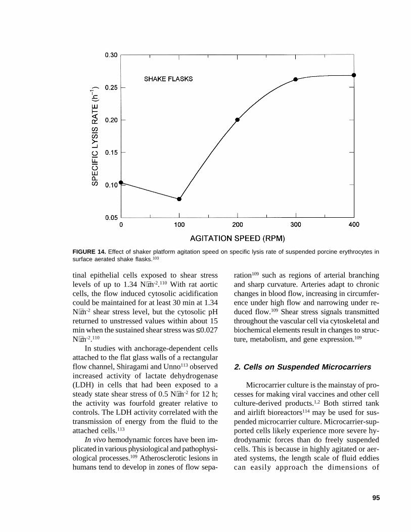
has been suggested for capillaries with sharp-edged entrances, and blood with a viscosity of4 × 10-3 Pa⋅s.76 This corresponds to a Reynoldsnumber of 1500 inside the capillary and anaverage wall shear rate of about 4800 s-1. Ve-locities as high as 17 m⋅s-1 (i.e., a Reynoldsnumber of ~4200) may be employed insidecapillaries with carefully flared entrances.76 Aswith other animal cells, erythrocytes subjectedto bubbling are susceptible to bubble rupture-associated damage;103 however, damage occursalso in surface aerated shake flasks, and thespecific lysis rate increases with increasingspeed of the shaker platform for the range of100 to 400 rpm, as shown in Figure 14. Theslight decline in lysis rate at 100 rpm (Figure14) was associated with improved surface aera-tion relative to a static flask.103
In comparison with erythrocytes, the cyto-plasm of leukocytes has markedly differentrheological properties,105 but the properties ofleukocyte membrane are similar to those of thered cell membrane. Leukocytes adhering tovascular endothelium detach when the shearstress is between 26.5 and 106.0 N⋅m-2.105 Ac-cording to work cited by Prokop and Bajpai,86
a shear stress level of 60 N⋅m-2 applied over 10min should lyse about one-fourth of a leuko-cyte population. In another study, sublethalshear stresses of 10 and 20 N⋅m-2 applied over10 min in a Couette viscometer affected thebiochemical response of human T cells relativeto unsheared controls.106 Therefore, it seems,that cells in vivo in circulation are apparentlymore shear resistant than ones studied in vitro.
B. Adherent Cells
1. Cells on Stationary Surfaces
Quite low shear stress levels, for example,between 0.25 and 0.60 N⋅m-2 in laminar flow,107
can interfere with the process of cell attach-ment to surfaces; however, once the cells are
attached and spread out, they may tolerate higherstresses. Prevailing shear stress also affects howcells orient during attachment and spread on asurface. In vitro studies in a parallel plate lami-nar flow chamber (τ = 2.3 N⋅m-2) confirmedthat surface adherent endothelial cells seededunder static conditions for 1 h, when exposedto flow, became oriented parallel to the flowaxis and were more elongated than ones grownunder static conditions.108 When the static in-cubation period was lengthened (24 to 48 h) sothat cells attained confluence, orientation wasdisparate and was not affected by subsequentflow. Morphological response of endothelialcells has been suggested as being indicative oflocal hydromechanical forces. A cell’s adap-tive response, for example, a reduced projectedarea relative to static conditions, reduces thefluid motion associated forces experienced bythe cell.108 The presence of suspended cellssuch as erythrocytes in the flowing fluid hasbeen observed to affect the spread of attachedendothelial cells. This effect is apparently dueto collisions between suspended erythrocytesand the endothelial cells and also due to theviscosity enhancing effect of suspended cells.Laminar shear stress of the order of 0.5 to 10.0N⋅m-2 may remove adherent cells from sur-faces,65 but even lower values (e.g., 0.1 to 1.0N⋅m-2) are known to affect cellular morphol-ogy, permeability, and gene expression.65
Sublethal shear stress levels cause no obvi-ous physical damage but may produce variousbiochemical and physiological responses.106,109-112
Shear stress strongly stimulates endothelial cellsto produce nitric oxide.111 Other physiologicalresponses have been reported. In studies withrat aortic endothelial cells anchored on the in-ternal walls of glass capillaries, laminar shearstress was shown to affect the cytosolic pHbecause of preferential leakage of certain ionsout of the cells into the buffer saline.110 Thisreversible permeability enhancement occurredeven at stress levels as low as 0.05 N⋅m-2 appliedover short durations (~2 min). Similar effectswere noted with human aortic endothelial cellsbut not with human skin fibroblasts or rat intes-
95
tinal epithelial cells exposed to shear stresslevels of up to 1.34 N⋅m-2.110 With rat aorticcells, the flow induced cytosolic acidificationcould be maintained for at least 30 min at 1.34N⋅m-2 shear stress level, but the cytosolic pHreturned to unstressed values within about 15min when the sustained shear stress was ≤0.027N⋅m-2.110
In studies with anchorage-dependent cellsattached to the flat glass walls of a rectangularflow channel, Shiragami and Unno113 observedincreased activity of lactate dehydrogenase(LDH) in cells that had been exposed to asteady state shear stress of 0.5 N⋅m-2 for 12 h;the activity was fourfold greater relative tocontrols. The LDH activity correlated with thetransmission of energy from the fluid to theattached cells.113
In vivo hemodynamic forces have been im-plicated in various physiological and pathophysi-ological processes.109 Atherosclerotic lesions inhumans tend to develop in zones of flow sepa-
ration109 such as regions of arterial branchingand sharp curvature. Arteries adapt to chronicchanges in blood flow, increasing in circumfer-ence under high flow and narrowing under re-duced flow.109 Shear stress signals transmittedthroughout the vascular cell via cytoskeletal andbiochemical elements result in changes to struc-ture, metabolism, and gene expression.109
2. Cells on Suspended Microcarriers
Microcarrier culture is the mainstay of pro-cesses for making viral vaccines and other cellculture-derived products.1,2 Both stirred tankand airlift bioreactors114 may be used for sus-pended microcarrier culture. Microcarrier-sup-ported cells likely experience more severe hy-drodynamic forces than do freely suspendedcells. This is because in highly agitated or aer-ated systems, the length scale of fluid eddiescan easily approach the dimensions of
FIGURE 14. Effect of shaker platform agitation speed on specific lysis rate of suspended porcine erythrocytes insurface aerated shake flasks.103
96
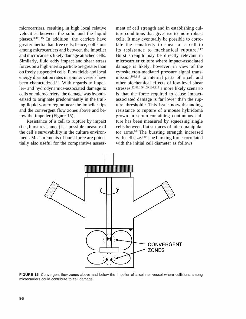
microcarriers, resulting in high local relativevelocities between the solid and the liquidphases.3,47,115 In addition, the carriers havegreater inertia than free cells; hence, collisionsamong microcarriers and between the impellerand microcarriers likely damage attached cells.Similarly, fluid eddy impact and shear stressforces on a high-inertia particle are greater thanon freely suspended cells. Flow fields and localenergy dissipation rates in spinner vessels havebeen characterized.116 With regards to impel-ler- and hydrodynamics-associated damage tocells on microcarriers, the damage was hypoth-esized to originate predominantly in the trail-ing liquid vortex region near the impeller tipsand the convergent flow zones above and be-low the impeller (Figure 15).
Resistance of a cell to rupture by impact(i.e., burst resistance) is a possible measure ofthe cell’s survivability in the culture environ-ment. Measurements of burst force are poten-tially also useful for the comparative assess-
ment of cell strength and in establishing cul-ture conditions that give rise to more robustcells. It may eventually be possible to corre-late the sensitivity to shear of a cell toits resistance to mechanical rupture.117
Burst strength may be directly relevant inmicrocarrier culture where impact-associateddamage is likely; however, in view of thecytoskeleton-mediated pressure signal trans-mission109,118 to internal parts of a cell andother biochemical effects of low-level shearstresses,82,86,106,109,110,119 a more likely scenariois that the force required to cause impact-associated damage is far lower than the rup-ture threshold.5 This issue notwithstanding,resistance to rupture of a mouse hybridomagrown in serum-containing continuous cul-ture has been measured by squeezing singlecells between flat surfaces of micromanipula-tor arms.80 The bursting strength increasedwith cell size.120 The bursting force correlatedwith the initial cell diameter as follows:
FIGURE 15. Convergent flow zones above and below the impeller of a spinner vessel where collisions amongmicrocarriers could contribute to cell damage.
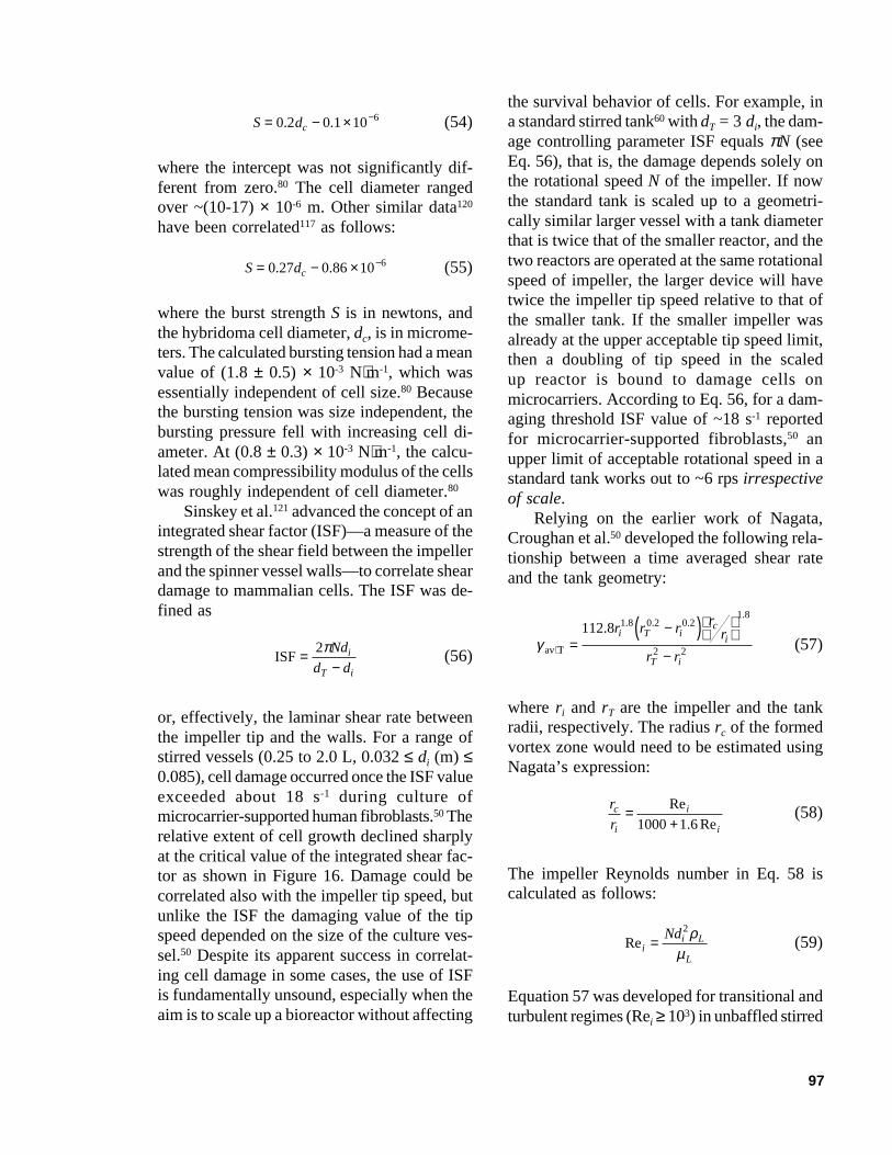
97
S dc= − × −0 2 0 1 106. . (54)
where the intercept was not significantly dif-ferent from zero.80 The cell diameter rangedover ~(10-17) × 10-6 m. Other similar data120
have been correlated117 as follows:
S dc= − × −0 27 0 86 106. . (55)
where the burst strength S is in newtons, andthe hybridoma cell diameter, dc, is in microme-ters. The calculated bursting tension had a meanvalue of (1.8 ± 0.5) × 10-3 N⋅m-1, which wasessentially independent of cell size.80 Becausethe bursting tension was size independent, thebursting pressure fell with increasing cell di-ameter. At (0.8 ± 0.3) × 10-3 N⋅m-1, the calcu-lated mean compressibility modulus of the cellswas roughly independent of cell diameter.80
Sinskey et al.121 advanced the concept of anintegrated shear factor (ISF)—a measure of thestrength of the shear field between the impellerand the spinner vessel walls—to correlate sheardamage to mammalian cells. The ISF was de-fined as
ISF=−
2πNd
d di
T i
(56)
or, effectively, the laminar shear rate betweenthe impeller tip and the walls. For a range ofstirred vessels (0.25 to 2.0 L, 0.032 ≤ di (m) ≤0.085), cell damage occurred once the ISF valueexceeded about 18 s-1 during culture ofmicrocarrier-supported human fibroblasts.50 Therelative extent of cell growth declined sharplyat the critical value of the integrated shear fac-tor as shown in Figure 16. Damage could becorrelated also with the impeller tip speed, butunlike the ISF the damaging value of the tipspeed depended on the size of the culture ves-sel.50 Despite its apparent success in correlat-ing cell damage in some cases, the use of ISFis fundamentally unsound, especially when theaim is to scale up a bioreactor without affecting
the survival behavior of cells. For example, ina standard stirred tank60 with dT = 3 di, the dam-age controlling parameter ISF equals πN (seeEq. 56), that is, the damage depends solely onthe rotational speed N of the impeller. If nowthe standard tank is scaled up to a geometri-cally similar larger vessel with a tank diameterthat is twice that of the smaller reactor, and thetwo reactors are operated at the same rotationalspeed of impeller, the larger device will havetwice the impeller tip speed relative to that ofthe smaller tank. If the smaller impeller wasalready at the upper acceptable tip speed limit,then a doubling of tip speed in the scaledup reactor is bound to damage cells onmicrocarriers. According to Eq. 56, for a dam-aging threshold ISF value of ~18 s-1 reportedfor microcarrier-supported fibroblasts,50 anupper limit of acceptable rotational speed in astandard tank works out to ~6 rps irrespectiveof scale.
Relying on the earlier work of Nagata,Croughan et al.50 developed the following rela-tionship between a time averaged shear rateand the tank geometry:
γav T⋅ =−( )
−
112 8 1 8 0 2 0 21 8
2 2
. . . ..
r r r rr
r r
i T ic
i
T i
(57)
where ri and rT are the impeller and the tankradii, respectively. The radius rc of the formedvortex zone would need to be estimated usingNagata’s expression:
r
rc
i
i
i
=+Re
. Re1000 1 6(58)
The impeller Reynolds number in Eq. 58 iscalculated as follows:
Reii L
L
Nd=2ρµ
(59)
Equation 57 was developed for transitional andturbulent regimes (Rei ≥ 103) in unbaffled stirred
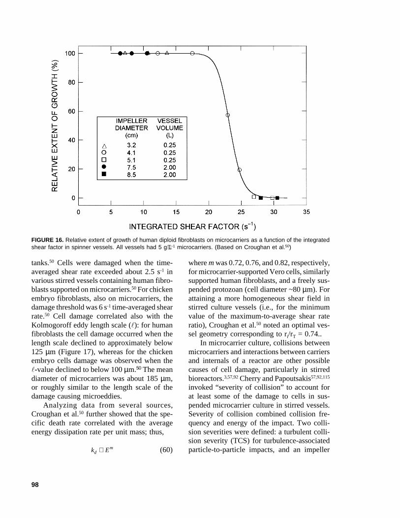
98
tanks.50 Cells were damaged when the time-averaged shear rate exceeded about 2.5 s-1 invarious stirred vessels containing human fibro-blasts supported on microcarriers.50 For chickenembryo fibroblasts, also on microcarriers, thedamage threshold was 6 s-1 time-averaged shearrate.50 Cell damage correlated also with theKolmogoroff eddy length scale (l): for humanfibroblasts the cell damage occurred when thelength scale declined to approximately below125 µm (Figure 17), whereas for the chickenembryo cells damage was observed when thel-value declined to below 100 µm.50 The meandiameter of microcarriers was about 185 µm,or roughly similar to the length scale of thedamage causing microeddies.
Analyzing data from several sources,Croughan et al.50 further showed that the spe-cific death rate correlated with the averageenergy dissipation rate per unit mass; thus,
k Edm∝ (60)
where m was 0.72, 0.76, and 0.82, respectively,for microcarrier-supported Vero cells, similarlysupported human fibroblasts, and a freely sus-pended protozoan (cell diameter ~80 µm). Forattaining a more homogeneous shear field instirred culture vessels (i.e., for the minimumvalue of the maximum-to-average shear rateratio), Croughan et al.50 noted an optimal ves-sel geometry corresponding to ri/rT = 0.74..
In microcarrier culture, collisions betweenmicrocarriers and interactions between carriersand internals of a reactor are other possiblecauses of cell damage, particularly in stirredbioreactors.3,57,92 Cherry and Papoutsakis57,92,115
invoked “severity of collision” to account forat least some of the damage to cells in sus-pended microcarrier culture in stirred vessels.Severity of collision combined collision fre-quency and energy of the impact. Two colli-sion severities were defined: a turbulent colli-sion severity (TCS) for turbulence-associatedparticle-to-particle impacts, and an impeller
FIGURE 16. Relative extent of growth of human diploid fibroblasts on microcarriers as a function of the integratedshear factor in spinner vessels. All vessels had 5 g⋅L-1 microcarriers. (Based on Croughan et al.50)
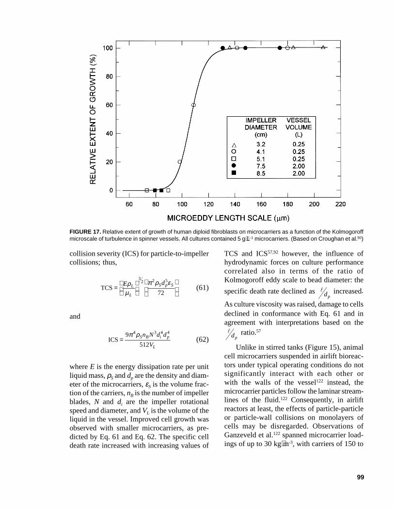
99
collision severity (ICS) for particle-to-impellercollisions; thus,
TCS=
E dL
L
S p Sρµ
π ρ ε3
2 2 5
72(61)
and
ICS=9
512
4 3 4 4π ρS B i p
L
n N d d
V(62)
where E is the energy dissipation rate per unitliquid mass, ρS and dp are the density and diam-eter of the microcarriers, εS is the volume frac-tion of the carriers, nB is the number of impellerblades, N and di are the impeller rotationalspeed and diameter, and VL is the volume of theliquid in the vessel. Improved cell growth wasobserved with smaller microcarriers, as pre-dicted by Eq. 61 and Eq. 62. The specific celldeath rate increased with increasing values of
TCS and ICS57,92 however, the influence ofhydrodynamic forces on culture performancecorrelated also in terms of the ratio ofKolmogoroff eddy scale to bead diameter: the
specific death rate declined as
ldp
increased.
As culture viscosity was raised, damage to cellsdeclined in conformance with Eq. 61 and inagreement with interpretations based on the
ldp
ratio.57
Unlike in stirred tanks (Figure 15), animalcell microcarriers suspended in airlift bioreac-tors under typical operating conditions do notsignificantly interact with each other orwith the walls of the vessel122 instead, themicrocarrier particles follow the laminar stream-lines of the fluid.122 Consequently, in airliftreactors at least, the effects of particle-particleor particle-wall collisions on monolayers ofcells may be disregarded. Observations ofGanzeveld et al.122 spanned microcarrier load-ings of up to 30 kg⋅m-3, with carriers of 150 to
FIGURE 17. Relative extent of growth of human diploid fibroblasts on microcarriers as a function of the Kolmogoroffmicroscale of turbulence in spinner vessels. All cultures contained 5 g⋅L-1 microcarriers. (Based on Croughan et al.50)
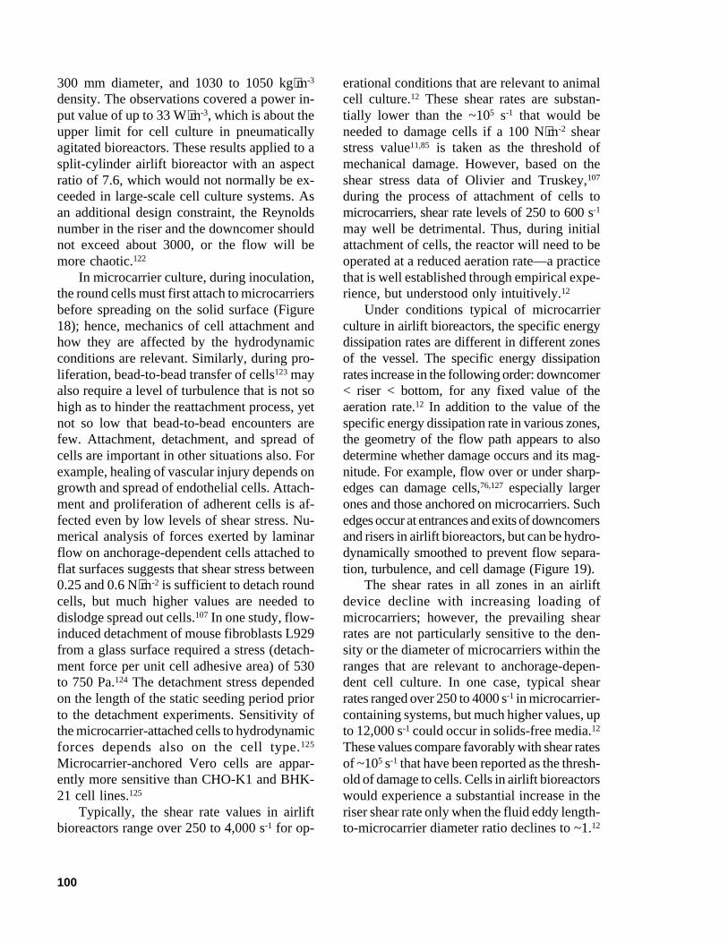
100
300 mm diameter, and 1030 to 1050 kg⋅m-3
density. The observations covered a power in-put value of up to 33 W⋅m-3, which is about theupper limit for cell culture in pneumaticallyagitated bioreactors. These results applied to asplit-cylinder airlift bioreactor with an aspectratio of 7.6, which would not normally be ex-ceeded in large-scale cell culture systems. Asan additional design constraint, the Reynoldsnumber in the riser and the downcomer shouldnot exceed about 3000, or the flow will bemore chaotic.122
In microcarrier culture, during inoculation,the round cells must first attach to microcarriersbefore spreading on the solid surface (Figure18); hence, mechanics of cell attachment andhow they are affected by the hydrodynamicconditions are relevant. Similarly, during pro-liferation, bead-to-bead transfer of cells123 mayalso require a level of turbulence that is not sohigh as to hinder the reattachment process, yetnot so low that bead-to-bead encounters arefew. Attachment, detachment, and spread ofcells are important in other situations also. Forexample, healing of vascular injury depends ongrowth and spread of endothelial cells. Attach-ment and proliferation of adherent cells is af-fected even by low levels of shear stress. Nu-merical analysis of forces exerted by laminarflow on anchorage-dependent cells attached toflat surfaces suggests that shear stress between0.25 and 0.6 N⋅m-2 is sufficient to detach roundcells, but much higher values are needed todislodge spread out cells.107 In one study, flow-induced detachment of mouse fibroblasts L929from a glass surface required a stress (detach-ment force per unit cell adhesive area) of 530to 750 Pa.124 The detachment stress dependedon the length of the static seeding period priorto the detachment experiments. Sensitivity ofthe microcarrier-attached cells to hydrodynamicforces depends also on the cell type.125
Microcarrier-anchored Vero cells are appar-ently more sensitive than CHO-K1 and BHK-21 cell lines.125
Typically, the shear rate values in airliftbioreactors range over 250 to 4,000 s-1 for op-
erational conditions that are relevant to animalcell culture.12 These shear rates are substan-tially lower than the ~105 s-1 that would beneeded to damage cells if a 100 N⋅m-2 shearstress value11,85 is taken as the threshold ofmechanical damage. However, based on theshear stress data of Olivier and Truskey,107
during the process of attachment of cells tomicrocarriers, shear rate levels of 250 to 600 s-1
may well be detrimental. Thus, during initialattachment of cells, the reactor will need to beoperated at a reduced aeration rate—a practicethat is well established through empirical expe-rience, but understood only intuitively.12
Under conditions typical of microcarrierculture in airlift bioreactors, the specific energydissipation rates are different in different zonesof the vessel. The specific energy dissipationrates increase in the following order: downcomer< riser < bottom, for any fixed value of theaeration rate.12 In addition to the value of thespecific energy dissipation rate in various zones,the geometry of the flow path appears to alsodetermine whether damage occurs and its mag-nitude. For example, flow over or under sharp-edges can damage cells,76,127 especially largerones and those anchored on microcarriers. Suchedges occur at entrances and exits of downcomersand risers in airlift bioreactors, but can be hydro-dynamically smoothed to prevent flow separa-tion, turbulence, and cell damage (Figure 19).
The shear rates in all zones in an airliftdevice decline with increasing loading ofmicrocarriers; however, the prevailing shearrates are not particularly sensitive to the den-sity or the diameter of microcarriers within theranges that are relevant to anchorage-depen-dent cell culture. In one case, typical shearrates ranged over 250 to 4000 s-1 in microcarrier-containing systems, but much higher values, upto 12,000 s-1 could occur in solids-free media.12
These values compare favorably with shear ratesof ~105 s-1 that have been reported as the thresh-old of damage to cells. Cells in airlift bioreactorswould experience a substantial increase in theriser shear rate only when the fluid eddy length-to-microcarrier diameter ratio declines to ~1.12
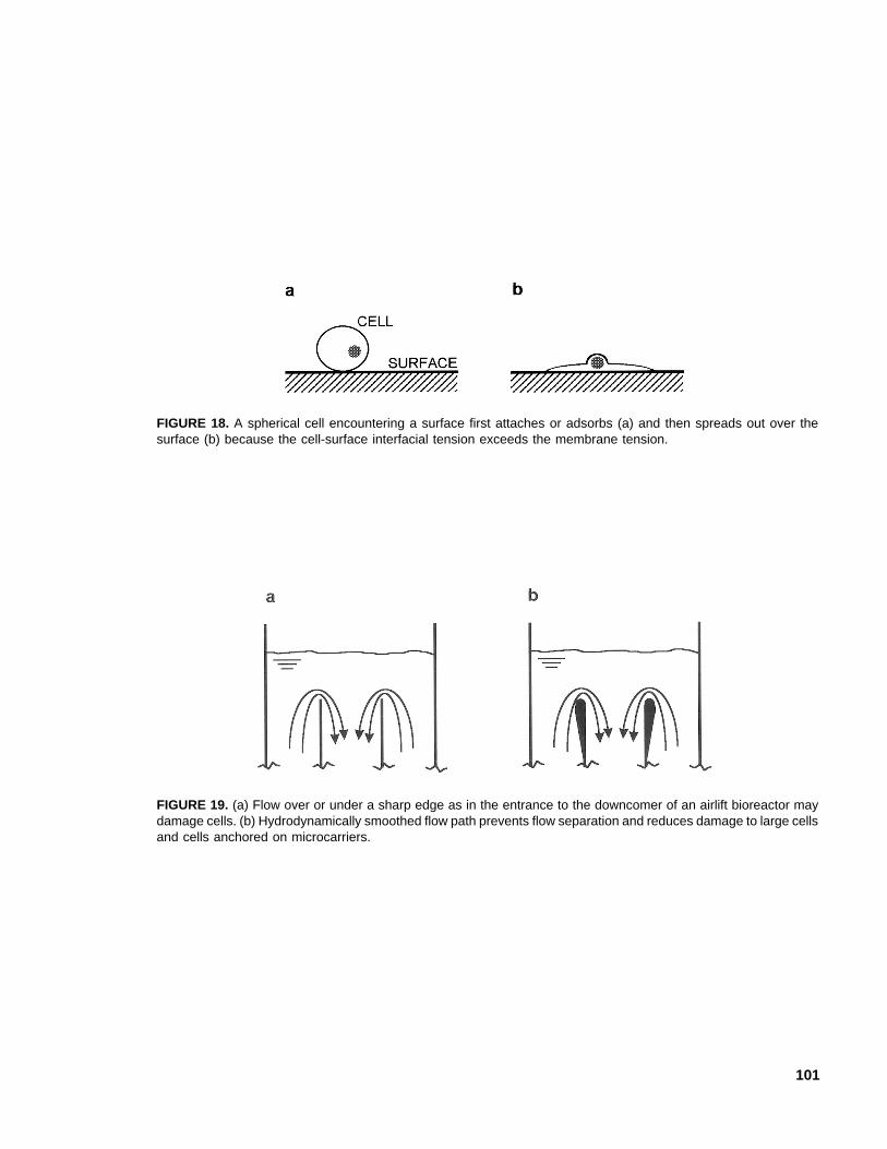
101
FIGURE 18. A spherical cell encountering a surface first attaches or adsorbs (a) and then spreads out over thesurface (b) because the cell-surface interfacial tension exceeds the membrane tension.
FIGURE 19. (a) Flow over or under a sharp edge as in the entrance to the downcomer of an airlift bioreactor maydamage cells. (b) Hydrodynamically smoothed flow path prevents flow separation and reduces damage to large cellsand cells anchored on microcarriers.
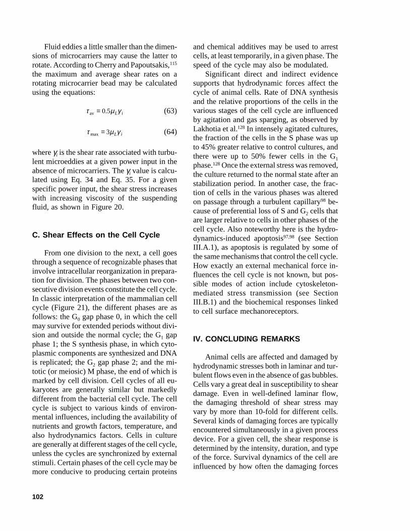
102
Fluid eddies a little smaller than the dimen-sions of microcarriers may cause the latter torotate. According to Cherry and Papoutsakis,115
the maximum and average shear rates on arotating microcarrier bead may be calculatedusing the equations:
τ µ γav = 0 5. L i (63)
τ µ γmax = 3 L i (64)
where γi is the shear rate associated with turbu-lent microeddies at a given power input in theabsence of microcarriers. The γi value is calcu-lated using Eq. 34 and Eq. 35. For a givenspecific power input, the shear stress increaseswith increasing viscosity of the suspendingfluid, as shown in Figure 20.
C. Shear Effects on the Cell Cycle
From one division to the next, a cell goesthrough a sequence of recognizable phases thatinvolve intracellular reorganization in prepara-tion for division. The phases between two con-secutive division events constitute the cell cycle.In classic interpretation of the mammalian cellcycle (Figure 21), the different phases are asfollows: the G0 gap phase 0, in which the cellmay survive for extended periods without divi-sion and outside the normal cycle; the G1 gapphase 1; the S synthesis phase, in which cyto-plasmic components are synthesized and DNAis replicated; the G2 gap phase 2; and the mi-totic (or meiosic) M phase, the end of which ismarked by cell division. Cell cycles of all eu-karyotes are generally similar but markedlydifferent from the bacterial cell cycle. The cellcycle is subject to various kinds of environ-mental influences, including the availability ofnutrients and growth factors, temperature, andalso hydrodynamics factors. Cells in cultureare generally at different stages of the cell cycle,unless the cycles are synchronized by externalstimuli. Certain phases of the cell cycle may bemore conducive to producing certain proteins
and chemical additives may be used to arrestcells, at least temporarily, in a given phase. Thespeed of the cycle may also be modulated.
Significant direct and indirect evidencesupports that hydrodynamic forces affect thecycle of animal cells. Rate of DNA synthesisand the relative proportions of the cells in thevarious stages of the cell cycle are influencedby agitation and gas sparging, as observed byLakhotia et al.128 In intensely agitated cultures,the fraction of the cells in the S phase was upto 45% greater relative to control cultures, andthere were up to 50% fewer cells in the G1
phase.128 Once the external stress was removed,the culture returned to the normal state after anstabilization period. In another case, the frac-tion of cells in the various phases was alteredon passage through a turbulent capillary98 be-cause of preferential loss of S and G2 cells thatare larger relative to cells in other phases of thecell cycle. Also noteworthy here is the hydro-dynamics-induced apoptosis97,98 (see SectionIII.A.1), as apoptosis is regulated by some ofthe same mechanisms that control the cell cycle.How exactly an external mechanical force in-fluences the cell cycle is not known, but pos-sible modes of action include cytoskeleton-mediated stress transmission (see SectionIII.B.1) and the biochemical responses linkedto cell surface mechanoreceptors.
IV. CONCLUDING REMARKS
Animal cells are affected and damaged byhydrodynamic stresses both in laminar and tur-bulent flows even in the absence of gas bubbles.Cells vary a great deal in susceptibility to sheardamage. Even in well-defined laminar flow,the damaging threshold of shear stress mayvary by more than 10-fold for different cells.Several kinds of damaging forces are typicallyencountered simultaneously in a given processdevice. For a given cell, the shear response isdetermined by the intensity, duration, and typeof the force. Survival dynamics of the cell areinfluenced by how often the damaging forces
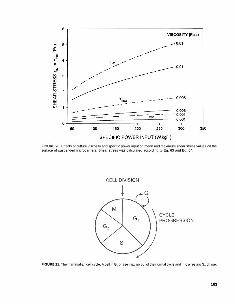
103
FIGURE 21. The mammalian cell cycle. A cell in G1 phase may go out of the normal cycle and into a resting G0 phase.
FIGURE 20. Effects of culture viscosity and specific power input on mean and maximum shear stress values on thesurface of suspended microcarriers. Shear stress was calculated according to Eq. 63 and Eq. 64.
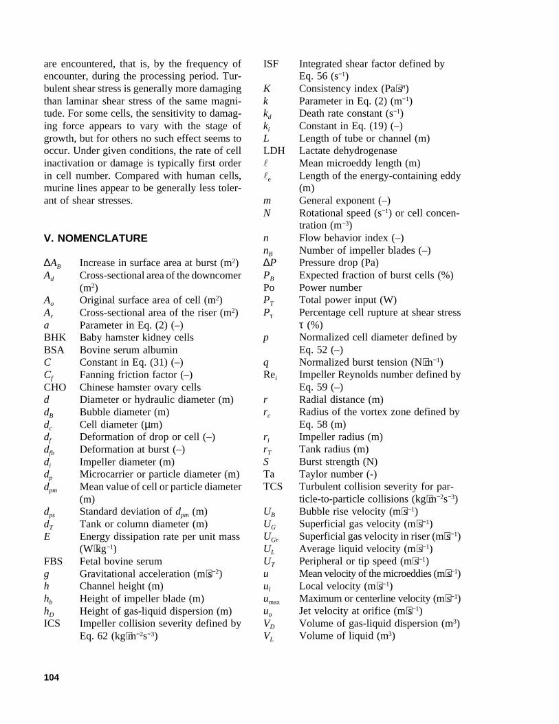
104
are encountered, that is, by the frequency ofencounter, during the processing period. Tur-bulent shear stress is generally more damagingthan laminar shear stress of the same magni-tude. For some cells, the sensitivity to damag-ing force appears to vary with the stage ofgrowth, but for others no such effect seems tooccur. Under given conditions, the rate of cellinactivation or damage is typically first orderin cell number. Compared with human cells,murine lines appear to be generally less toler-ant of shear stresses.
V. NOMENCLATURE
∆AB Increase in surface area at burst (m2)Ad Cross-sectional area of the downcomer
(m2)Ao Original surface area of cell (m2)Ar Cross-sectional area of the riser (m2)a Parameter in Eq. (2) (–)BHK Baby hamster kidney cellsBSA Bovine serum albuminC Constant in Eq. (31) (–)Cf Fanning friction factor (–)CHO Chinese hamster ovary cellsd Diameter or hydraulic diameter (m)dB Bubble diameter (m)dc Cell diameter (µm)df Deformation of drop or cell (–)dfb Deformation at burst (–)di Impeller diameter (m)dp Microcarrier or particle diameter (m)dpm Mean value of cell or particle diameter
(m)dps Standard deviation of dpm (m)dT Tank or column diameter (m)E Energy dissipation rate per unit mass
(W⋅kg−1)FBS Fetal bovine serumg Gravitational acceleration (m⋅s−2)h Channel height (m)hb Height of impeller blade (m)hD Height of gas-liquid dispersion (m)ICS Impeller collision severity defined by
Eq. 62 (kg⋅m−2s−3)
ISF Integrated shear factor defined byEq. 56 (s−1)
K Consistency index (Pa⋅sn)k Parameter in Eq. (2) (m−1)kd Death rate constant (s−1)ki Constant in Eq. (19) (–)L Length of tube or channel (m)LDH Lactate dehydrogenasel Mean microeddy length (m)le Length of the energy-containing eddy
(m)m General exponent (–)N Rotational speed (s−1) or cell concen-
tration (m−3)n Flow behavior index (–)nB Number of impeller blades (–)∆P Pressure drop (Pa)PB Expected fraction of burst cells (%)Po Power numberPT Total power input (W)Pτ Percentage cell rupture at shear stress
τ (%)p Normalized cell diameter defined by
Eq. 52 (–)q Normalized burst tension (N⋅m−1)Rei Impeller Reynolds number defined by
Eq. 59 (–)r Radial distance (m)rc Radius of the vortex zone defined by
Eq. 58 (m)ri Impeller radius (m)rT Tank radius (m)S Burst strength (N)Ta Taylor number (-)TCS Turbulent collision severity for par-
ticle-to-particle collisions (kg⋅m−2s−3)UB Bubble rise velocity (m⋅s−1)UG Superficial gas velocity (m⋅s−1)UGr Superficial gas velocity in riser (m⋅s−1)UL Average liquid velocity (m⋅s−1)UT Peripheral or tip speed (m⋅s−1)u Mean velocity of the microeddies (m⋅s−1)ul Local velocity (m⋅s−1)umax Maximum or centerline velocity (m⋅s−1)uo Jet velocity at orifice (m⋅s−1)VD Volume of gas-liquid dispersion (m3)VL Volume of liquid (m3)
105
Vs Effective energy dissipation volume orthe volume swept by the impeller (m3)
W Width of the impeller blade (m)w Viscometer gap width (m)x Distance along x axis (m)y Distance along y axis (m)Z Parameter defined by Eq. 50 (–)
A. Greek Symbols
β Parameter in Eq. 30 (–)γ Shear rate (s−1)γav Average shear rate (s−1)γav⋅T Time-averaged shear rate (s−1)γI Shear rate in the region around the
impeller (s−1)γi Isotropic turbulence shear rate defined
by Eq. 34 (s−1)γmax Time averaged maximum shear rate
(s−1)γw Wall shear rate (s−1)εS Volume fraction of microcarriers or
solids (–)η Constant in Eq. 33 (–)θ Parameter defined by Eq. 48 (–)µap Effective or apparent viscosity (Pa⋅s)µd Viscosity of the drop phase (Pa⋅s)µL Viscosity of liquid (Pa⋅s)π Pi (-)ρL Density of liquid (kg⋅m−3)ρS Density of microcarriers or solid (kg⋅m−3)σ Interfacial tension or membrane ten-
sion (N⋅m−1)σB Membrane tension at cell burst
(N⋅m−1)σBm Mean value of σB (N⋅m−1)σBs Standard deviation of σBm (N⋅m−1)τ Shear stress (N⋅m−2)τav Average value of Kolmogoroff shear
stress on microcarrier (N⋅m−2)τmax Maximum value of Kolmogoroff shear
stress on microcarrier (N⋅m−2)τmax J Maximum shear stress in a submerged
free jet (N⋅m−2)τw Wall shear stress (N⋅m−2)ϕ Parameter defined by Eq. 44 (–)
REFERENCES
1. Lubiniecki, A.S., Ed., 1990. Large-Scale Mamma-lian Cell Culture Technology. Dekker, New York.
2. Spier, R.E., Ed., 2000. Encyclopedia of Cell Tech-nology, John Wiley, New York.
3. Papoutsakis, E.T., 1991. Fluid-mechanical dam-age of animal cells in bioreactors. TrendsBiotechnol. 9, 427–437.
4. Papoutsakis, E.T., 1991. Media additives for pro-tecting freely suspended animal cells against agi-tation and aeration damage. Trends Biotechnol.9, 316–324.
5. Chisti, Y., 1999. Shear sensitivity. In: Flickinger,M.C., Drew, S.W. (Eds.), in Encyclopediaof Bioprocess Technology: Fermentation,Biocatalysis, and Bioseparation. Vol. 5, JohnWiley, New York, pp. 2379–2406.
6. Chisti, Y., 2000. Animal-cell damage in spargedbioreactors. Trends Biotechnol. 18, 420–432.
7. Chattopadhyay, D., Garcia-Briones, M., Venkat,R., and Chalmers, J.J., 1997. Hydrodynamic prop-erties in bioreactors. In: Hauser, H., Wagner, R.(Eds.), Mammalian Cell Biotechnology in Pro-tein Production. Walter de Gruyter & Co., Ber-lin, pp. 319–343.
8. Chalmers, J.J., 1998. Gas bubbles and their in-fluence on microorganisms. Appl. Mech. Rev.51, 113–120.
9. Hua, J., Erickson, L.E., Yiin, T.-Y., and Glasgow,L.A., 1993. Review of the effects of shear andinterfacial phenomena on cell viability. Crit. Rev.Biotechnol. 13, 305–328.
10. Augenstein, D.C., Sinskey, A.J., and Wang,D.I.C., 1971. Effect of shear on the death of twostrains of mammalian tissue cells. Biotechnol.Bioeng. 13, 409–418.
11. Born, C., Zhang, Z., Al-Rubeai, M., and Tho-mas, C.R., 1992. Estimation of disruption ofanimal cells by laminar shear stress. Biotechnol.Bioeng. 40, 1004–1010.
12. Grima, E., Chisti, Y., and Moo-Young, M., 1997.Characterization of shear rates in airliftbioreactors for animal cell culture. J. Biotechnol.54, 195–210.
13. McQueen, A., Meilhoc, E., and Bailey, J.E., 1987.Flow effects on the viability and lysis of sus-
106
pended mammalian cells. Biotechnol. Lett. 9,831–836.
14. Ludwig, A., Kretzmer, G., and Schügerl, K.,1992. Determination of a “critical shear stresslevel” applied to adherent mammalian cells.Enzyme Microb. Technol. 14, 209–213.
15. Shiragami, N., 1994. Development of a newmethod for testing strength of cells against fluidshear stress. Bioprocess Eng. 10, 47–51.
16. Thomas, C.R., 1990. Problems of shear in bio-technology. In: Winkler, M.R. (Ed.), ChemicalEngineering Problems in Biotechnology.Elsevier, London, pp. 23–93.
17. Chisti, Y., 1989. Airlift Bioreactors. Elsevier,London.
18. Chisti, Y., 1998. Pneumatically agitatedbioreactors in industrial and environmentalbioprocessing: Hydrodynamics, hydraulics andtransport phenomena. Appl. Mech. Rev. 51, 33–112.
19. Chisti, Y. and Moo-Young, M., 1989. On thecalculation of shear rate and apparent viscosityin airlift and bubble column bioreactors.Biotechnol. Bioeng. 34, 1391–1392.
20. Lutkemeyer, D., Ameskamp, N., Tebbe, H.,Wittler, J., and Lehmann, J., 1999. Estimation ofcell damage in bench- and pilot-scale affinityexpanded-bed chromatography for the purifica-tion of monoclonal antibodies. Biotechnol.Bioeng. 65, 114–119.
21. Chisti, Y., 1998. Strategies in downstream pro-cessing. In: Subramanian, G. (Ed.), Bioseparationand Bioprocessing: A Handbook. Vol. 2, Wiley-VCH, New York, pp. 3–30.
22. Vogel, J.H. and Kroner, K.-H., 1999. Controlledshear filtration: a novel technique for animal cellseparation. Biotechnol. Bioeng. 63, 663–674.
23. Arathoon, W.R. and Birch, J.R., 1986. Large-scale cell culture in biotechnology. Science 232,1390–1395.
24. Birch, J.R., Lambert, K., Thompson, P.W.,Kenney, A.C., and Wood, L.A., 1987. Antibodyproduction with airlift fermentors. In: Lydersen,B.K. (Ed.), Large Scale Cell Culture Technol-ogy. Hanser Publishers, New York, pp. 1–20.
25. Emery, A.N., Lavery, M., Williams, B., andHanda, A., 1987. Large-scale hybridoma cul-ture. In: Webb, C., Mavituna, F. (Eds.), Plant
and Animal Cells: Process Possibilities. EllisHorwood, Chichester, pp. 137–146.
26. Handa, A., Emery, A.N., and Spier, R.E., 1987.On the evaluation of gas-liquid interfacial ef-fects on hybridoma viability in bubble columnbioreactors. Devel. Biol. Stand. 66, 241–253.
27. Handa-Corrigan, A., Emery, A.N., and Spier,R.E., 1989. Effect of gas-liquid interfaces on thegrowth of suspended mammalian cells: mecha-nisms of cell damage by bubbles. Enzyme Microb.Technol. 11, 230–235.
28. Jöbses, I., Martens, D., and Tramper, J., 1991.Lethal events during gas sparging in animal cellculture. Biotechnol. Bioeng. 37, 484–490.
29 Martens, D.E., de Gooijer, C.D., Beuvery, E.C.,and Tramper, J., 1992. Effect of serum concen-tration on hybridoma viable cell density and pro-duction of monoclonal antibodies in CSTRs andon shear sensitivity in air-lift loop reactors.Biotechnol. Bioeng. 39, 891–897.
30. Tramper, J., Joustra, D., and Vlak, J.M., 1987.Bioreactor design for growth of shear-sensitiveinsect cells. In: Webb, C., Mavituna, F. (Eds.),Plant and Animal Cells: Process Possibilities.Ellis Horwood, Chichester, pp. 125–136.
31. Tramper, J., Smit, D., Straatman, J., and Vlak,J.M., 1987. Bubble column design for growth offragile insect cells. Bioprocess Eng. 2, 37–41.
32. Shi, L.K., Riba, J.P., and Angelino, H., 1990.Estimation of effective shear rate for aeratednon-Newtonian liquids in airlift bioreactor. Chem.Eng. Commun. 89, 25–35.
33. Nishikawa, M., Kato, H., and Hashimoto, K.,1977. Heat transfer in aerated tower filled withnon-Newtonian liquid. Ind. Eng. Chem. ProcessDes. Develop. 16, 133–137.
34. Henzler, H.J., 1980. Begasen höherviskoserFlüssigkeiten. Chem. -Ing. -Techn. 52, S 643–652.
35. Henzler, H.J. and Kauling, J., 1985. Scale-up ofmass transfer in highly viscous liquids. Presentedat the 5th European Conference on Mixing,Würzberg, Germany, paper 30, BHRA, Cranfield,pp. 303–312.
36. Schumpe, A. and Deckwer, W.-D., 1987. Vis-cous media in tower bioreactors: Hydrodynamiccharacteristics and mass transfer properties.Bioprocess Eng. 2, 79–94.
107
37. Kawase, Y. and Moo-Young, M., 1986. Influ-ence of non-Newtonian flow behaviour on masstransfer in bubble columns with and withoutdraft tubes. Chem. Eng. Commun. 40, 67–83.
38. Kawase, Y. and Kumagai, T., 1991. Apparentviscosity for non-Newtonian fermentation me-dia in bioreactors. Bioprocess Eng. 7, 25–28.
39. Al-Masry, W.A., 1999. Effect of scale-up onaverage shear rates for aerated non-Newtonianliquids in external loop airlift reactors. Biotechnol.Bioeng. 62, 494–498.
40. Hoffmann, J., Buescher, K., and Hempel, D.C.,1995. Determination of maximum shear-stressin stirred vessels. (In German.) Chem. -Ing. -Techn. 67, 210–214.
41. Robertson, B. and Ulbrecht, J.J., 1987. Measure-ment of shear rate on an agitator in a fermenta-tion broth. In: Ho, C.S., Oldshue, J.Y. (Eds.),Biotechnology Processes: Scale-Up and Mixing.American Institute of Chemical Engineers, NewYork, pp. 31–35.
42. Chisti, Y., Halard, B. and Moo-Young, M., 1988.Liquid circulation in airlift reactors. Chem. Eng.Sci. 43, 451–457.
43. Hülscher, M., Pauli, J., and Onken, U., 1990.Influence of protein concentration on mechani-cal cell damage and fluid dynamics in airliftreactors for mammalian cell culture. FoodBiotechnol. 4(1), 157–166.
44. Okada, K., Shibano, S., and Akagi, Y., 1993.Turbulent properties in bubble-flow region inexternal-loop airlift bubble column. J. Chem.Eng. Jpn 26, 637–643.
45. Lübbert, A. and Larson, B., 1990. Detailed in-vestigations of the multiphase flow in airlift towerloop reactors. Chem. Eng. Sci. 45, 3047–3053.
46. Lübbert, A., Larson, B., Wan, L.W., and Bröring,S., 1990. Local mixing behaviour of airliftmultiphase chemical reactors. I. Chem. E. Symp.Ser. 121, 203–213.
47. Chisti, Y., 1993. Animal cell culture in stirredbioreactors: observations on scale-up. BioprocessEng. 9, 191–196.
48. Elias, C.B., Desai, R.B., Patole, M.S., Joshi,J.B., and Mashelkar, R.A., 1995. Turbulent shearstress–effect on mammalian cell culture and mea-surement using laser doppler anemometer. Chem.Eng. Sci. 50, 2431–2440.
49. Michaels, J.D., Petersen, J.F., McIntire, L.V.,and Papoutsakis, E.T., 1991. Protection mecha-nisms of freely suspended animal cells (CRL8018) from fluid-mechanical injury. Viscomet-ric and bioreactor studies using serum, PluronicF68 and polyethylene glycol. Biotechnol. Bioeng.38, 169–180.
50. Croughan, M.S., Hamel, J.-F., and Wang, D.I.C.,1987. Hydrodynamic effects on animal cellsgrown in microcarrier cultures. Biotechnol.Bioeng. 29, 130–141.
51. Croughan, M.S., Sayre, E.S., and Wang, D.I.C.,1989. Viscous reduction of turbulent damage inanimal cell culture. Biotechnol. Bioeng. 33, 862–872.
52. Lavery, M. and Nienow, A.W., 1987. Oxygentransfer in animal cell culture medium.Biotechnol. Bioeng. 30, 368–373.
53. Oh, S.K.W., Nienow, A.W., Al-Rubeai, M., ndEmery, A.N., 1989. The effects of agitation in-tensity with and without continuous sparging onthe growth and antibody production of hybri-doma cells. J. Biotechnol. 12, 45–62.
54. Oh, S.K.W., Nienow, A.W., Al-Rubeai, M., andEmery, A.N., 1992. Further studies of the cul-ture of mouse hybridomas in an agitatedbioreactor with and without continuous sparging.J. Biotechnol. 22, 245–270.
55. Smith, C.G. and Greenfield, P.F., 1992. Me-chanical agitation of hybridoma suspension cul-tures: metabolic effects of serum, Pluronic F68,and albumin supplements. Biotechnol. Bioeng.40, 1045–1055.
56. van der Pol, L. and Tramper, J., 1998. Shearsensitivity of animal cells from a culture-me-dium perspective. Trends Biotechnol. 16, 323–328.
57. Cherry, R.S. and Papoutsakis, E.T., 1989. Growthand death rates of bovine embryonic kidney cellsin turbulent microcarrier bioreactors. BioprocessEng. 4, 81–89.
58. Bowen, R., 1986. Unraveling the mysteries ofshear-sensitive mixing systems. Chem. Eng. June9, 55–63.
59. Calderbank, P.H. and Moo-Young, M.B., 1959.The prediction of power consumption in theagitation of non-Newtonian fluids. Trans. I.Chem. E. 37, 26–33.
108
60. Chisti, Y. and Moo-Young, M., 1999. Fermenta-tion technology, bioprocessing, scale-up andmanufacture. In: Moses, V., Cape, R.E.,Springham, D.G. (Eds.), Biotechnology: TheScience and the Business. 2nd ed., HarwoodAcademic Publishers, New York, pp. 177–222.
61. Candia, J.-L.F. and Deckwer, W.-D., 1999.Xanthan gum. In: Flickinger, M.C., Drew, S.W.(Eds.), Encyclopedia of Bioprocess Technology:Fermentation, Biocatalysis, and Bioseparation.Vol. 5, John Wiley, New York, pp. 2695–2711.
62. Jan, D.C.-H., Emery, A.N. and Al-Rubeai, M.,1993. Use of a spin-filter can reduce disruptionof hybridoma cells in a bioreactor. Biotechnol.Techniques 7, 351–356.
63. LaPorte, T.L., Shevitz, J., Kim, Y., and Wang,S.S., 1996. Long term shear effects on a hybri-doma cell line by dynamic perfusion devices.Bioprocess Eng. 15, 1–7.
64. Chisti, Y., 1992. Assure bioreactor sterility.Chem. Eng. Progress 88(9), 80–85.
65. Aunins, J.G. and Henzler, H.-J., 1993. Aerationin cell culture bioreactors. In: Rehm, H.-J., Reed,G. (Eds.), Biotechnology. Vol. 3, 2nd ed., VCH,Weinheim, pp. 219–281.
66. Chisti, Y., 1999. Mass transfer. In: Flickinger,M.C., Drew, S.W. (Eds.), Encyclopediaof Bioprocess Technology: Fermentation,Biocatalysis, and Bioseparation. Vol. 3, JohnWiley, New York, pp. 1607–1640.
67. Baldyga, J., Bourne, J.R., and Zimmerman, B.,1994. Investigation of mixing in jet reactors us-ing fast, competitive-consecutive reactions.Chem. Eng. Sci. 49, 1937–1946.
68. Baldyga, J., Bourne, J.R., and Gholap, R.V.,1995. The influence of viscosity on mixing in jetreactors. Chem. Eng. Sci. 50, 1877–1880.
69. Nienow, A.W., 1998. Hydrodynamics of stirredbioreactors. Appl. Mech. Rev. 51, 3–32.
70. Michaels, J.D., Mallik, A.K., and Papoutsakis,E.T., 1996. Sparging and agitation-induced in-jury of cultured animal cells: do cell-to-bubbleinteractions in the bulk liquid injure cells?Biotechnol. Bioeng. 51, 399–409.
71. Meier, S.J., Hatton, T.A., and Wang, D.I.C., 1999.Cell death from bursting bubbles: role of cellattachment to rising bubbles in sparged reactors.Biotechnol. Bioeng. 62, 468–478.
72. Cherry, R.S. and Kwon, K.-Y., 1990. Transientshear stresses on a suspension cell in turbulence.Biotechnol. Bioeng. 36, 563–571.
73. Wu, J., 1995. Mechanism of animal cell damageassociated with gas bubbles and cell protectionby medium additives. J. Biotechnol. 43, 81–94.
74. Gore, R.A. and Crowe, C.T., 1989. Effect ofparticle size on modulating turbulent intensity.Int. J. Multiphase Flow 15, 279–285.
75. Caulet, P.J.C., van der Lans, R.G.J.M., and Luyben,K.Ch.A.M., 1996. Hydrodynamical interactionsbetween particles and liquid flows in biochemicalapplications. Chem. Eng. J. 62, 193–206.
76. Blackshear, P.L. and Blackshear, G.L., 1987.Mechanical hemolysis. In: Skalak, R., Chien, S.(Eds.), Handbook of Bioengineering. McGraw-Hill, New York, pp. 15.1–15.19.
77. Garcia-Briones, M.A. and Chalmers, J.J., 1994.Flow parameters associated with hydrodynamiccell injury. Biotechnol. Bioeng. 44, 1089–1098.
78. Chisti, Y. and Moo-Young, M., 1986. Disrup-tion of microbial cells for intracellular products.Enzyme Microb. Technol. 8, 194–204.
79. Taylor, G.I., 1934. The formation of emulsionsin definable fields of flow. Proc. Roy. Soc. 146,501–525.
80. Zhang, Z., Ferenczi, M.A., and Thomas, C.R.,1992. A micromanipulation technique with atheoretical cell model for determining mechani-cal properties of single mammalian cells. Chem.Eng. Sci. 47, 1347–1354.
81. Lawden, D.F., 1980. Elliptic Functions and Appli-cations. Springer-Verlag, New York, pp. 100–102.
82. Abu-Reesh, I. and Kargi, F., 1989. Biologicalresponses of hybridoma cells to defined hydro-dynamic shear stress. J. Biotechnol. 9, 167–178.
83. Midler, M. and Finn, R.K., 1966. A model sys-tem for evaluating shear in the design of stirredfermentors. Biotechnol. Bioeng. 8, 71–84.
84. Zhong, J.-J., Fujiyama, K., Seki, T., and Yoshida,T., 1994. A quantitative analysis of shear effectson cell suspension and cell culture of Perillafrutescens in bioreactors. Biotechnol. Bioeng. 44,649–654.
85. Doran, P.M., 1993. Design of reactors for plantcells and organs. Adv. Biochem. Eng. Biotechnol.48, 115–168.
109
86. Prokop, A., Bajpai, R.K., 1992. The sensitivityof biocatalysts to hydrodynamic shear stress. Adv.Appl. Microbiol. 37, 165–232.
87. Petersen, J.F., McIntire, L.V., and Papoutsakis,E.T., 1990. Shear sensitivity of hybridoma cellsin batch, fed-batch, and continuous cultures.Biotechnol. Prog. 6, 114–120.
88. Shiragami, N., 1997. Effect of shear rate onhybridoma cell metabolism. Bioprocess Eng. 16,345–347.
89. Abu-Reesh, I. and Kargi, F., 1991. Biologicalresponses of hybridoma cells to hydrodynamicshear in an agitated bioreactor. Enzyme Microb.Technol. 13, 913–919.
90. Kioukia, N., Nienow, A.W., Al-Rubeai, M., andEmery, A.N., 1996. Influence of agitation andsparging on the growth rate and infection ofinsect cells in bioreactors and a comparison withhybridoma culture. Biotechnol. Prog. 12, 779–785.
91. Cook, J.A. and Mitchell, J.B., 1989. Viabilitymeasurements in mammalian cell systems. Anal.Biochem. 179, 1–7.
92. Cherry, R.S. and Papoutsakis, E.T., 1988. Physi-cal mechanisms of cell damage in microcarriercell culture bioreactors. Biotechnol. Bioeng. 32,1001–1014.
93. McQueen, A. and Bailey, J.E., 1989. Influenceof serum level, cell line, flow type and viscosityon flow-induced lysis of suspended mammaliancells. Biotechnol. Lett. 11, 531–536.
94. Ramirez, O.T. and Mutharasan, R., 1992. Effectof serum on the plasma membrane fluidity ofhybridomas: an insight into its shear protectivemechanism. Biotechnol. Prog. 8, 40–50.
95. Goldblum, S., Bae, Y.-K., Hink, W.F., andChalmers, J.J., 1990. Protective effect of methylcellulose and other polymers on insect cells sub-jected to laminar shear stress. Biotechnol. Prog.6, 383–390.
96. Kunas, K.T. and Papoutsakis, E.T., 1990. The pro-tective effect of serum against hydrodynamic dam-age of hybridoma cells in agitated and surface-aerated bioreactors. J. Biotechnol. 15, 57–70.
97. Al-Rubeai, M., Singh, R.P., Goldman, M.H.,and Emery, A.N., 1995. Death mechanisms ofanimal cells in conditions of intensive agitation.Biotechnol. Bioeng. 45, 463–472.
98. Al-Rubeai, M., Singh, R.P., Emery, A.N., andZhang, Z., 1995. Cell-cycle and cell-size depen-dence of susceptibility to hydrodynamic-forces.Biotechnol. Bioeng. 46, 88–92.
99. Butler, M., Huzel, N., Barnabé, N., Gray, T., and Bajno,L., 1999. Linoleic acid improves the robustness of cellsin agitated cultures. Cytotechnology 30, 27–36.
100. Palomares, L.A., González, M., Ramírez, O.T.,2000. Evidence of Pluronic F-68 direct interac-tion with insect cells: impact on shear protec-tion, recombinant protein, and baculovirus pro-duction. Enzyme Microb. Technol. 26, 324–331.
101. Kim, B.-Y., Putnam, A.J., Kulik, T.J., andMooney, D.J., 1998. Optimizing seeding andculture methods to engineer smooth muscle tis-sue on biodegradable polymer matrices.Biotechnol. Bioeng. 57, 46–54.
102. Hochmuth, R.M., 1987. Properties of red bloodcells. In: Skalak, R., Chien, S. (Eds.), Handbookof Bioengineering. McGraw-Hill, New York, pp.12.1–12.17.
103. Zhang, Z., Chisti, Y., and Moo-Young, M., 1995.Effects of the hydrodynamic environment andshear protectants on survival of erythrocytes insuspension. J. Biotechnol. 43, 33–40.
104. Ramírez, O.T. and Mutharasan, R., 1990. Therole of the plasma membrane fluidity on the shearsensitivity of hybridomas grown under hydrody-namic stress. Biotechnol. Bioeng. 36, 911–920.
105. Schmid-Schönbein, G.W., 1987. Rheology ofleukocytes. In: Skalak, R., Chien, S. (Eds.), Hand-book of Bioengineering. McGraw-Hill, NewYork, pp. 13.1–13.25.
106. Chittur, K.K., McIntire, L.V., and Rich, R.R.,1988. Shear stress effects on human T cell func-tion. Biotechnol. Prog. 4(2), 89–96.
107. Olivier, L.A. and Truskey, G.A., 1993. A nu-merical analysis of forces exerted by laminarflow on spreading cells in a parallel plate flowchamber assay. Biotechnol. Bioeng. 42, 963–973.
108. Sirois, E., Charara, J., Ruel, J., Dussault, J.C.,Gagnon, P., and Doillon, C.J., 1998. Biomaterials19, 1925–1934. Endothelial cells exposed toerythrocytes under shear stress: an in vitro study.
109. Papadaki, M. and Eskin, S.G., 1997. Effects offluid shear stress on gene regulation of vascularcells. Biotechnol. Prog. 13, 209–221.
110
110. Ziegelstein, R.C., Cheng, L., and Capogrossi,M.C., 1992. Flow-dependent cytosolic acidifica-tion of vascular endothelial cells. Science 258,656–659.
111. Niebauer, J., Dulak, J., Chan, J.R., Tsao, P.S.,and Cooke, J.P., 1999. Gene transfer of nitricoxide synthase: Effects on endothelial biology.J. Am. Coll. Cardiol. 34, 1201–1207.
112. Lakhotia, S., Bauer, K.D., and Papoutsakis, E.T.,1993. Fluid-mechanical forces in agitatedbioreactors reduce the CD13 and CD33 surfaceproteins content of HL60 cells. Biotechnol.Bioeng. 41, 868–877.
113. Shiragami, N. and Unno, H., 1994. Effect ofshear stress on activity of cellular enzyme inanimal cell. Bioprocess Eng. 10, 43–45.
114. Dai, X., Ouyang, F., and Qi, Y., 1994. Prelimi-nary investigation on anchorage-dependent cellculture by air-lift suspending microcarriers. In:Teo, W.K., Yap, M.G.S., Oh, S.K.W. (Eds.), BetterLiving Through Biochemical Engineering. Uni-versity of Singapore, Singapore, pp. 408–410.
115. Cherry, R.S. and Papoutsakis, E.T., 1986. Hy-drodynamic effects on cells in agitated tissueculture reactors. Bioprocess Eng. 1, 29–41.
116. Venkat, R.V., Stock, L.R. and Chalmers, J.J.,1996. Study of hydrodynamics in microcarrierculture spinner vessels: a particle trackingvelocimetry approach. Biotechnol. Bioeng. 49,456–466.
117. Chisti, Y. and Moo-Young, M., 1993. Effec-tively use fragile biocatalysts in bioreactors.Chimica Oggi 11(3–4), 25–27.
118. Cherry, R.S., 1993. Animal cells in turbulent flu-ids: Details of the physical stimulus and the bio-logical response. Biotechnol. Adv. 11, 279–299.
119. Toshisuke, M., Hiroki, K., Koji, M., Masao, Y.,and Yoshio, Y., 1993. Disruption of cytoskeletalstructures mediates endotheline-1 gene expres-
sion in cultured porcine aortic endothelial cells.J. Clin. Invest. 92, 1706–1712.
120. Zhang, Z., Ferenczi, M.F., Lush, A.C., and Tho-mas, C.R., 1991. A novel micromanipulationtechnique for measuring the bursting strength ofsingle mammalian cells. Appl. Microbiol.Biotechnol. 36, 208–210.
121. Sinskey, A.J., Fleishaker, R.J., Tyo, M.A., Giard,D.-J., and Wang, D.I.C., 1981. Production ofcell-derived products: virus and interferon. Ann.N. Y. Acad. Sci. 369, 47–59.
122. Ganzeveld, K.J., Chisti, Y., and Moo-Young,M., 1995. Hydrodynamic behaviour of animalcell microcarrier suspensions in split-cylinderairlift bioreactors. Bioprocess Eng. 12, 239–247.
123. Wang, Y. and Ouyang, F., 1999. Bead-to-beadtransfer of Vero cells in microcarrier culture.Bioprocess Eng. 21, 211–213.
124. Yamamoto, A., Mishima, S., Maruyama, N., andSumita, M., 1998. A new technique for directmeasurement of the shear force necessary todetach a cell from a material. Biomaterials 19,871–879.
125. Wu, S.-C., 1999. Influence of hydrodynamicshear stress on microcarrier-attached cell growth:Cell line dependency and surfactant protection.Bioprocess Eng. 21, 201–206.
126. Williams, A.R., 1973. Viscoelasticity of the hu-man erythrocyte membrane. Biorheology 10,313–319.
127. Suzuki, T., Matsuo, T., Ohtaguchi, K., and Koide,K., 1995. Gas-sparged bioreactors for CO2 fixa-tion by Dunaliella tertiolecta. J. Chem. Technol.Biotechnol. 62, 351–358.
128. Lakhotia, S., Bauer, K.D., and Papoutsakis, E.T.,1992. Damaging agitation intensities increaseDNA-synthesis rate and alter cell-cycle phasedistributions of CHO cells. Biotechnol. Bioeng.40, 978–990.
Top Related