


Languages
Pages
Legal


Hydro-Guard Flushing & Monitoring SystemsHydro-Guard automatic flushing and monitoring systems are used by utilities throughout North America to maintain water quality throughout their distribution systems. These systems can be programmed to flush on a scheduled sequence and to monitor a variety of water quality conditions, including chlorine residuals, temperature, pH, flow, turbidity, and pressure.
In areas within the distribution system where it is difficult to maintain an acceptable level of disinfectant residual, or where taste, color or odor issues are leading to customer complaints, Mueller Co. provides automated flushing and water quality sampling solutions. The Hydro-Guard system can be programmed to flush a line and monitor water quality conditions in distribution piping. When conditions warrant, the device automatically initiates flushing and helps a utility to comply with USEPA Safe Drinking Water Standards. This system conserves water, reduces chlorine consumption, and improves customer satisfaction, while requiring minimal supervision by utility personnel. • By maintaining water quality with a higher degree of consistency, Hydro-Guard helps utilities reduce complaints, improve compliance and lower operating costs.
Since pressure management in pipe networks is fundamental to providing safe drinking water, Mueller Co. provides a user-friendly and cost-effective technology to continuously monitor pressure in potable water distribution systems. The pressure monitoring system, typically installed in DMAs or pressure zones; on PRVs; system interconnnects; and water storage tanks, reports at user-defined intervals via cellular service. Data is logged; made available for periodic upload; and stored for up to two years on a secure web server. When a pressure spike occurs, utility personnel can be notified within minutes by email and text messaging. This technology is currently available in North America only. • By monitoring pressure, infrastructure failures can be avoided, non-revenue water can be reduced, energy costs can be reduced and public safety is improved.
HG-6 Portable Flushing System HG-3 Permanent Flushing System Remote Pressure Monitoring System
Item Description:Hydro-Guard® HG-1 utilizes a 12" air gap to prevent backflow. According to the associated part number, this device is to have 2" piping and valve; be constructed of Schedule 80 PVC; have an 18" bury depth; and be housed in a low-profile, above grade, light green enclosure.
HG1AIN2PVC018LPLGHG1 A IN 2 PVC 018 LPLG
HG
-1 A
tmos
heric
Dis
char
ge
Air G
ap B
ackfl
ow
Built-
in (N
OD
E) P
rogr
amm
er
2" In
let V
alve
PVC
Pip
e M
ater
ial
18" B
ury
Dep
th
Low
Pro
file,
Lig
ht G
reen
§§
§
Part Numbering Example
Components in contact with potable water will also comply with latest requirements of the Federal Safe Drinking Water Act.
HYDRO-GUARD® FLUSHING & MONTORING SYSTEMS
Shaded area indicates change Rev. 2-16
16.1
HYDRO-GUARD® TEMPORARY(PORTABLE) FLUSHING SYSTEMS
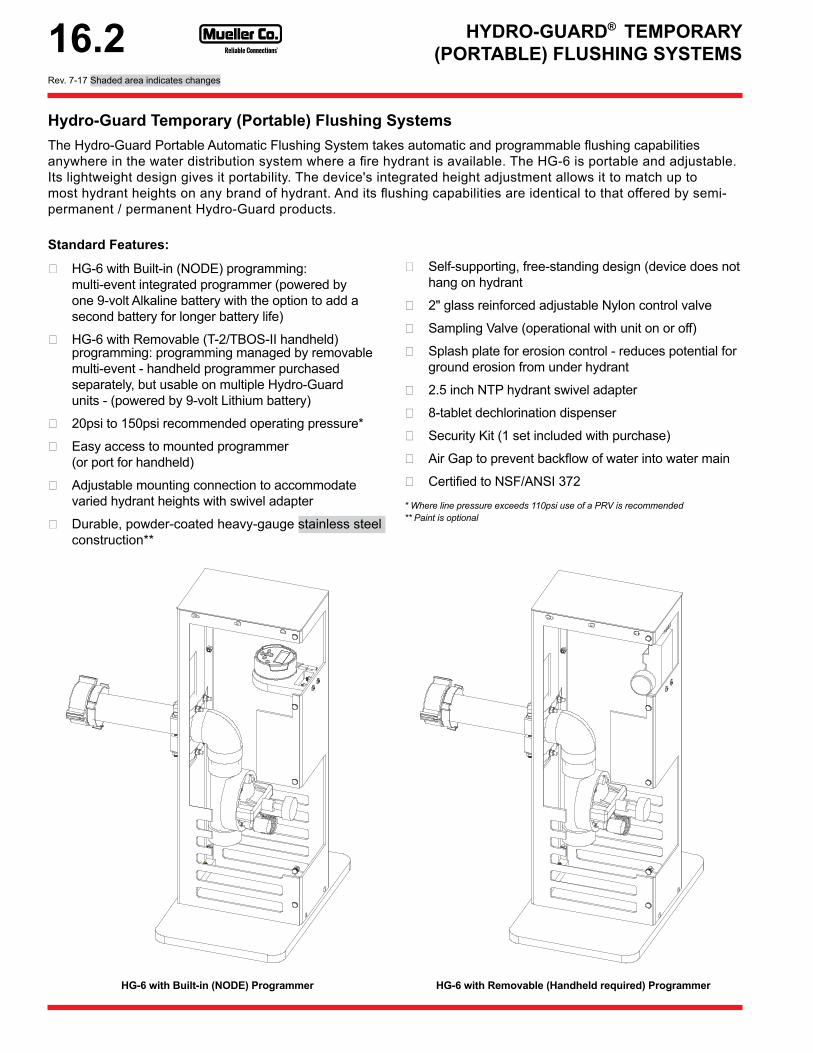
Hydro-Guard Temporary (Portable) Flushing SystemsThe Hydro-Guard Portable Automatic Flushing System takes automatic and programmable flushing capabilities anywhere in the water distribution system where a fire hydrant is available. The HG-6 is portable and adjustable. Its lightweight design gives it portability. The device's integrated height adjustment allows it to match up to most hydrant heights on any brand of hydrant. And its flushing capabilities are identical to that offered by semi-permanent / permanent Hydro-Guard products.
Standard Features:
❏ HG-6 with Built-in (NODE) programming: multi-event integrated programmer (powered by one 9-volt Alkaline battery with the option to add a second battery for longer battery life)
❏ HG-6 with Removable (T-2/TBOS-II handheld) programming: programming managed by removable multi-event - handheld programmer purchased separately, but usable on multiple Hydro-Guard units - (powered by 9-volt Lithium battery)
❏ 20psi to 150psi recommended operating pressure*
❏ Easy access to mounted programmer (or port for handheld)
❏ Adjustable mounting connection to accommodate varied hydrant heights with swivel adapter
❏ Durable, powder-coated heavy-gauge stainless steel construction**
HG-6 with Built-in (NODE) Programmer
❏ Self-supporting, free-standing design (device does not hang on hydrant
❏ 2" glass reinforced adjustable Nylon control valve
❏ Sampling Valve (operational with unit on or off)
❏ Splash plate for erosion control - reduces potential for ground erosion from under hydrant
❏ 2.5 inch NTP hydrant swivel adapter
❏ 8-tablet dechlorination dispenser
❏ Security Kit (1 set included with purchase)
❏ Air Gap to prevent backflow of water into water main
❏ Certified to NSF/ANSI 372
* Where line pressure exceeds 110psi use of a PRV is recommended** Paint is optional
HG-6 with Removable (Handheld required) Programmer
Rev. 7-17 Shaded area indicates changes
16.2

Hydro-Guard (Hydrant Mount) ■ HG6 = Hydrant Mount /
Discharges to Ground
Backflow Prevention ■ A = Air Gap
Programming
❏ IN = Built-In (NODE)
❏ RM = Removavle (T-2) 5
❏ SM = SMART Controller Upgrade 6
Valve/Inlet Size ■ 2 = 2" Valve & Piping
Pipe Material
❏ BRN = No Lead Brass Piping (includes Dechlor and Sampling)
❏PVC = Brass Connection with Schedule 80 PVC Piping 4; Dechlor and Sampling are not included
Bury Depth ■ 000 = None / Hydrant Mount
Enclosure Type
❏ LPUN = Unpainted 4
❏ LPRR = Red
❏ LPYY = Yellow
4 - Unpainted enclosures are only available with Hydrant Flushing models that are equipped with Schedule 80 PVC piping and do not require dechlorination system.5 - Where an "RM" code is indicated for controller type a handheld controller will be required. The handheld controller (PN: 545687) is sold separately. One handheld controller can be used to manage programming on an unlimited number of "RM" equipped flushing systems. 6 - Where an "SM" code is indicated for controller type a SMART Multi-Parameter Monitoring and Flushing Controller will be utilized. As of this date, the SMART Multi-Parameter Controller will monitor for up to three water quality parameters (analyzers sold separately) including chlorine, temperature, pH, pressure and turbidity.
Ordering GuideTo order a Hydro-Guard automatic flushing and monitoring system, simply choose the desired options from the chart below and contact your Mueller Sales Representative for pricing. ■ indicates option is included with the unit.
HYDRO-GUARD® TEMPORARY (PORTABLE)FLUSHING SYSTEMS ORDERING GUIDE
HG-6 Flushing System
Shaded area indicates change Rev. 7-17
Stainless Steel Housing
16.3

HYDRO-GUARD® PERMANENT FLUSHING SYSTEMS
Hydro-Guard Permanent Flushing SystemsHydro-Guard Permanent Flushing Systems provide a fully automated solution for flushing water distribution lines. The units can be designed to operate reliably in warm and cold climates. Designed for use with a built-in (NODE) multi-event programmer, Hydro-Guard systems are programmed to flush a water line multiple times per day, seven days a week, with flush durations ranging from one minute to six hours per program. Water can be discharged atmospherically onto the system's splash plate or direct into a sewer system.
Standard Features:
❏ Programming managed by a multi-event battery powered handheld programmer (9-volt Alkaline battery)
❏ Battery and programming interface accessible from top of unit (9-volt Lithium)
❏ 20psi to 150psi recommended operating pressure (valve rated to 200psi) (for pressures in excess of 110psi the use of a PRV is recommended).
❏ Free standing design
❏ Lockable, polyethylene housing provides durability, UV and impact resistance
❏ Cold climate units feature a patented freeze protection system features a self-draining dual check valve
HG-3
❏ The HG-1 & HG-3 feature an energy dissipating stain-less steel shield and integral heavy-duty UV protected splash plate (est. 135 gpm).
❏ OEM-installed Dechlorination System (8-tablet capacity)
❏ OEM-installed Sampling System (allows sample collection with unit on or off)
❏ Security Kit (1 set included with purchase)
❏ HG-3 & HG-4 Cold climate units feature a patented Cam-Lock™ Release System
❏ HG-8 Cold climate & HG-8 Warm climate devices are below grade designs with only a lid at grade
❏ Certified to NSF/ANSI 372
TJM 3/17/14
HG-8 DIRECT DISCHARGE ASSEMBLY
Complete 1" Valve and Meter Replacement Assembly 546779
1" Coiled Tubing Assy
Cast Iron Vault Lid 546787
HG8 Plate Rest 546799
21" Dia. Below-Grade Vault 790015
Reinforcing Ring 700014
2" Foam Insulation Pad 546785
9-Volt Lithium Battery HG-A102L
1" CoiledTubing Assembly
Reinforced Ring700014
Complete 1" Valve& Meter ReplacementAssembly546779
9-Volt Lithium BatteryHG-A102L
21" Diameter Below-Grade Vault790015
2" FoamInsulation Pad546785
HG-8 Plate Rest546799
Vault Lid546787
HG-8 Cold ClimateHG-1HG-8 Warm Climate
Rev. 4-17 Shaded area indicates changes
16.4

WARM CLIMATES
Hydro-Guard WARM Climate (without freeze protection)
Discharge
❏ HG1 = On the Ground 8
❏ HG2 = Direct Discharge
❏HG8 = Direct Discharge - Flushing System Below Grade; Direct Flush to Storm Sewer, Pond or Swale 7
Backflow Prevention
❏ A = Air Gap
❏ D = Double Check 1
❏ R = RPZ 1
Programming
❏ IN = Built-In (NODE)
❏ RM = Removable (T-2) 5
❏ SM = SMART Controller Upgrade 6
Inlet Size ❏ 2 = 2"
Pipe Material❏ PVC = Schedule 80 PVC
❏ BRN = No Lead Brass
Bury Depth
❏ 000 = None
❏ 018 = 18" (HG-1 & HG-2 only)
❏ 036 = 36" (HG-8 WC only)
❏ 042 = 42" (HG-8 WC only)
Enclosure Type
❏ LPLG = Low Profile, Green
❏ HPLG = High Profile, Green
❏ HPTN = High Profile, Tan
❏ UNGD = (only available for HG-8)
COLD CLIMATES
Hydro-Guard COLD Climate (with freeze protection)
Discharge
❏ HG3 = Flush onto Ground 7
❏HG4 = Direct Flush to Storm Sewer, Pond or Swale 7
❏HG8 = Flushing System Below Grade; Direct Flush to Storm Sewer, Pond or Swale 7
Backflow Prevention❏ A = Air Gap
❏ D = Double Check 1
Programming
❏ IN = Built-In (NODE)
❏ RM = Removable (T-2) 5
❏ SM = SMART Controller Upgrade 6
Inlet Size❏ 1 = 1" (only available for HG-8)
❏ 2 = 2"
Pipe Material❏ PVC = Schedule 80 PVC
❏ BRN = No Lead Brass
Bury Depth
❏ 018 = 18"
❏ 036 = 36"
❏ 048 = 48"
❏ 060 = 60"
❏ 084 = 84"
❏ 108 = 108"
Enclosure Type❏ LPLG = Low Profile, Green
❏ UNGD = None 2, 3
1 - Double Check or RPZ backflow prevention is only offered on devices with an 18” bury depth and low profile enclosure, with the exception of any device that is constructed using a Below Grade enclosure (I.E. HG-8 Warm Climate)2 - HG-8 cold climate is only available with 1” poly-coil tubing and brass fittings 3 - Minimum bury depth for HG-8 cold climate flushing system with no above-grade enclosure is estimated to be 48"5 - Where an "RM" code is indicated for controller type a handheld controller will be required. The handheld controller (PN: 545687) is sold separately. One handheld controller can be used to manage programming on an unlimited number of "RM" equipped flushing systems.6 - Where an "SM" code is indicated for controller type a SMART Multi-Parameter Monitoring and Flushing Controller will be utilized. The SMART Multi-Parameter Controller will monitor for up to five water quality parameters (analyzers sold separately) including chlorine, temperature, pH, pressure and turbidity7 - For cold climates the Low Pressure Relief Valve / Double Check freeze protection system is utilized to prevent freeze damage. When the flushing system ceases to flush the water in the service lines of the device are drained of water to reduce the possibility of freeze damage.8 - TVC freeze protection is only available on the HG-11Basic/S [HG1A--2---000LPLG] andHG-2 style devices.
HYDRO-GUARD® PERMANENT FLUSHING SYSTEMS ORDERING INSTRUCTIONS
Ordering InstructionsTo order a Hydro-Guard automatic flushing and monitoring system, simply choose the desired options from the chart below and contact your Mueller Sales Representative for pricing. ■ indicates option is included with the unit.
Optional Equipment
545687 ❏ TBOS II handheld
-TCV ❏ Option TCV freeze protection 8
Shaded area indicates change Rev. 5-17
HSZ0060010/HG-A134 ❏ HG-5 Hydrant Defender with HG-6 lock (red)
HSZ0060014/HG-A134 ❏ HG-5 Hydrant Defender with HG-6 lock (yellow)
16.5

HYDRO-GUARD® S.M.A.R.T. FLUSHMANAGEMENT OPTIONS
Hydro-Guard S.M.A.R.T. Flush Management OptionsThe Hydro-Guard S.M.A.R.T. Flushing System is the ultimate automated flush management system. S.M.A.R.T. enabled flushing can be set to occur either by scheduled flush times or in response to real-time analysis of local water quality. What's more it allows two-way communication and remote flush and water quality management via either a secure web portal or a secure interface with end-user's existing SCADA via MODBUS TCP protocol.
By way of this two-way communication, the utility can receive near-time updates from each Hydro-Guard Unit in the distribution system equipped with the S.M.A.R.T. controller. It can be integrated with a residual analyzer and a variety of other water quality management devices. This integration will allow the Hydro-Guard S.M.A.R.T. Flushing System to flush only when the disinfectant residual drops below the parameters established by the end-user, as opposed to flushing on a set time based schedule. S.M.A.R.T. technology takes water conservation and cost management to a whole new level of potential savings.
Standard Features:
❏ Hydro-Guard S.M.A.R.T. Controller
❏ Hydro-Guard S.M.A.R.T. Management RTU with Ethernet
❏ Premium grade analyzers and sensors
❏ Web-based two way management software
❏ MODBUS TCP for SCADA integration
❏ Monitor multiple water quality parameters (chlorine, temperature, pH, turbidity, etc.)
❏ System management assisted by remote telemetry
❏ Premium grade protective enclosure with optional tamper notification
❏ Weather-proof protective enclosure
❏ Hydro-Guard Flushing System (model to be determined through client/Hydro-Guard consultation)
S.M.A.R.T. Flushing System
Rev. 12-16 Shaded area indicates changes
16.6

STEP 1 - SELECT MODEL
Selection Code Special Instructions
Select One
S.M.A.R.T. Controller SM 6 - ■STEP 2 - SELECT CHLORINE ANALYZER
Total Chlorine/ Mueller Specified TC - ❏
Free Chlorine/ Mueller Specified FC - ❏
STEP 3 - SELECT RADIO COMMUNICATION OPTION
Cellular Radio (GSM) G - ❏
Cellular Radio (CDMA) A - ❏
Ethernet Radio ET - ❏
Bluetooth Radio BT Can be added to other Radio options ❏
Wireless LAN Wifi WF - ❏
2.4 gHz / End User Spec 24 - ❏
STEP 4 - SELECT ANTENNA OPTION
Low Profile L - ❏
Boom Antenna (Responsibility of End User) U - ❏
No Antenna Required N - ❏
STEP 5 - SELECT BACKFLOW OPTION
Air Gap AG - ❏
Double Check Valve 1 DC - ❏
Reduced Pressure Zone (RPZ) 1 RZ - ❏
STEP 5 - SELECT ENCLOSURE / HOUSING
Ground Mount 33" Height G3 - ❏
Ground Mount 60" Height G6 - ❏
STEP 6 - SELECT POWER SOURCE
120 - Volt AC AC - ■
1 - Double Check or RPZ backflow prevention is only offered on devices with an 18” bury depth and low profile enclosure, with the exception of any device that is constructed using a Below Grade enclosure.
6 - Where an "SM" code is indicated for controller type a SMART Multi-Parameter Monitoring and Flushing Controller will be utilized. The SMART Multi-Parameter Controller will monitor for up to five water quality parameters (analyzers sold separately) including chlorine, temperature, pH, pressure and turbidity.
Ordering InstructionsTo order a Hydro-Guard automatic flushing and monitoring system, simply choose the desired options from the chart below and contact your Mueller Sales Representative for pricing. ■ indicates option is included with the unit.
HYDRO-GUARD® S.M.A.R.T. FLUSHORDERING INSTRUCTIONS
STEP 7 - SELECT FREEZE PROTECTION
Selection Code Special Instructions
Select One
Heater FH - ❏
Heater + Heat Tape FT - ❏
No Heater Required NF - ❏
STEP 8 - SELECT SYSTEM SECURITY
Tamper Switch T - ❏
Flow Detection Sensor F - ❏
Manual On/Off Switch M - ❏
No Security Option Required N - ❏
STEP 9 - SELECT WATER QUALITY MONITORING SENSORS
Chlorine Analyzer CL - ■pH Sensor PH - ❏
Turbidity Sensor TU - ❏
Control Valve with PRV PV
Flow Meter / Control Valve Combo** FM - ❏
Temperature Sensor TP Reports: GPM/Total ❏
TOC Sensor TC - ❏
Pressure PS - ❏
STEP 10 - SELECT HYDRO-GUARD FLUSHING DEVICE (REQUIRED)
HG-6 S.M.A.R.T. HG6B B = Brass ❏ Brass
HG-7 All-in-One Enclosure HG7A B = Brass, P = PVC
❏ Brass❏ SCH80 PVC
HG-7 All-in-One Enclosure HG7D B = Brass, P = PVC
❏ Brass❏ SCH80 PVC
Shaded area indicates change Rev. 5-17
16.7

HYDRO-GUARD®
SAMPLING STATIONS
Hydro-Guard Sampling StationsThe Hydro-Guard Blow-Off Sampling Station (B.O.S.S.) provides a reliable and user-friendly method for taking water quality samples from a utility's own water distribution line. Using a permanent, dedicated sampling point allows utility personnel to access sample locations at their convenience—no appointment necessary. Hydro-Guard Sampling Stations are for use in warm or cold climates, with a variety of freeze protection options available for the protection of these devices in even the coldest of climates.
Standard Features: ❏ Bury depths of 12" to 72"
❏ No lead brass or stainless steel piping components
❏ Free standing, self-supporting needs no additional pad or post
❏ Self-locking enclosure❏ HDPE or Powder-coated
aluminum, lockable support frame with powder-coating for corrosion resistance
Optional Features: ❏ Mechanical thermal control
valve freeze protection❏ Internal curb stop and
drain freeze protection
❏ Internal curb stop with VAC line freeze protection
UV Protected, Impact ResistantLockable Enclosure 9.5" Square , 25" Tall
3/8" Sample PortBrass or Stainless Steel
1/4" Sample Port Ball Valve
External 1" MuellerCurb Stop (Optional)
Distribution Line
Supplied by Others
Base & Frame (StandardPowdercoated Steel or 316SS)
3/8" Internal PipingBrass or Stainless Steel
Stainless Steel Support Clamps TYP. 2
MUELLER CONFIDENTIALTITLE TO AND OWNERSHIP OF
THIS ENGINEERING DATA REMAINS
IN MUELLER CO. NO USE IS TO BE
MADE OF THIS DATA EXCEPT ASSPECIFICALLY AUTHORIZED BY
MUELLER CO. ASSENT ON THE
PART OF RECIPIENTS TO THESE
CONDITIONS IS PRESUMED.
BSS05-CHA-00-SPTypical Install
DATE: 12/10/2012 (887)-864-8500DWG: TJMCleveland, TN
BSS05-CHA-00-SP Cold Climate Sample Station Installation
B.O.S.S. BSS-02 Sample Station with TCV
style freeze protection
Above Grade Solutions Below Grade SolutionsStandard Features: ❏ Incorporated into Mueller Relocator with horizontal
inlet and outlet❏ M.I.P. meter thread used to retrofit dual check
with sampling into existing meter set❏ Available for use with 5/8”; 5/8” x ¾”; ¾”; and 1”
meter setters❏ Sampling wand (sold separately)❏ Easy access ❏ No above grade housing to maintain❏ Sanitary cap included for protection of sample
quick connect at meter setter❏ No lead brass or stainless steel quick connect
valve for sure-fit connection of sample wand and sample point
❏ No valve to open at meter setter connection ❏ Wand constructed of 3/8” stainless steel tubing
with a ball valve
Sampling Wand: 547800(for use with all
samplers & relocators)
5/8" x 3/4" Relocator: 203H1445 - - - - 02N
(for use with 5/8"x3/4" SEAERS)
Rev. 4-17 Shaded area indicates changes
16.8

STEP 1 - SELECT MODEL
Type Code Select OneBlow-Off Sampling Station BSS ■STEP 2 - SELECT BLOW OFF SIZENo Blow Off Valve Included (DIV or CHA) 05 ❏
1" Blow Off Valve Included (DIV or CHA) 01 ❏
2" Blow Off Valve Included (CHA) 02 ❏
NOTE: 1" Station CHA Enclosure Option
STEP 3 - SELECT BURY DEPTH12" (standard) 12 ■36" 36 ❏
54" 54 ❏
60" 60 ❏
72" 72 ❏
STEP 4 - ENCLOSURE & COLORCHA Enclosures for 1" Models
Blue CHABL ❏
Light Green CHALG ❏
Dark Green CHADG ❏
CHA Enclosures for 2" Models
Blue CHABL ❏
Light Green CHALG ❏
Dark Green CHADG ❏
MUE Heavy Gauge Aluminum Powder Coated Enclosures
Dark Green 1" MUDG1 ❏
Water Blue 1" MUWB1 ❏
Brown 1" MUBR1 ❏
Purple 1" MURP1 ❏
Dark Green 2" MUDG2 ❏
Water Blue 2" MUWB2 ❏
Brown 2" MUBR2 ❏
Purple 2" MUPR2 ❏
Custom Sizes Call ❏OPTIONS
Item Used On CodeTD Key All DIV HG-A2006
Hex/Shoulder Bolt Key All CHA HG-A2023
Curb Stop Key CSR, CSD, VCS HG-20087
ID Tag *** Any Model HG-20033
Vacuum Pump VAC & VCS HG-A107
2" MPT x 2.5" NST 2" BSS HG-29011
Cyber Lock Key All CHA HG-A2008Notes:* Vacuum without Curb Stop only available on 12" models** 316 Stainless Steel frame for SGE070739CHA16 or SGE101042CHA16 Enclosures*** 3 lines and 25 characters per lineAll Safety Guard BOSS products can be custom built to meet the utilities specifications.
Ordering InstructionsTo order a Hydro-Guard automatic flushing and monitoring system, simply choose the desired options from the chart below and contact your Mueller Sales Representative for pricing. ■ indicates option is included with the unit.
STEP 5 - SELECT FREEZE PROTECTION
Type Code Select OneNo Freeze Protection 000 ■Vacuum Port for Manual Vacuum * VAC ❏
Thermal Control Valve - Auto Discharge of Water TCV ❏
Curb Stop that can be shut off after use CSR ❏
Curb Stop that drains after shut off CSD ❏
Vacuum Port for Manual Vacuum with Curb Stop VCS ❏
STEP 5 - SELECT INTERNAL COMPONENTSNo Lead Brass Component Construction NL ■Stainless Steel Interior Component Construction 12" SS ❏
Stainless Steel Interior Component Construction 36" SS ❏
Stainless Steel Interior Component Construction 54" SS ❏
Stainless Steel Interior Component Construction 60" SS ❏
Stainless Steel Interior Component Construction 72" SS ❏
STEP 6 - SELECT ENCLOSURE SUPPORT FRAMEStandard Powder-Coated Steel 00 ❏
316 Stainless Steel ** 16 ❏
HYDRO-GUARD® SAMPLING STATIONS ORDERING INSTRUCTIONS
Shaded area indicates change Rev. 4-17
Above Ground Sample Stations
Below Ground Sample Stations
Code Size Select One203H1445----02N 5/8"x3/4" ❏
- 5/8" ❏
- 3/4" ❏
- 1" ❏
547800 Universal sampling wand ❏
16.9
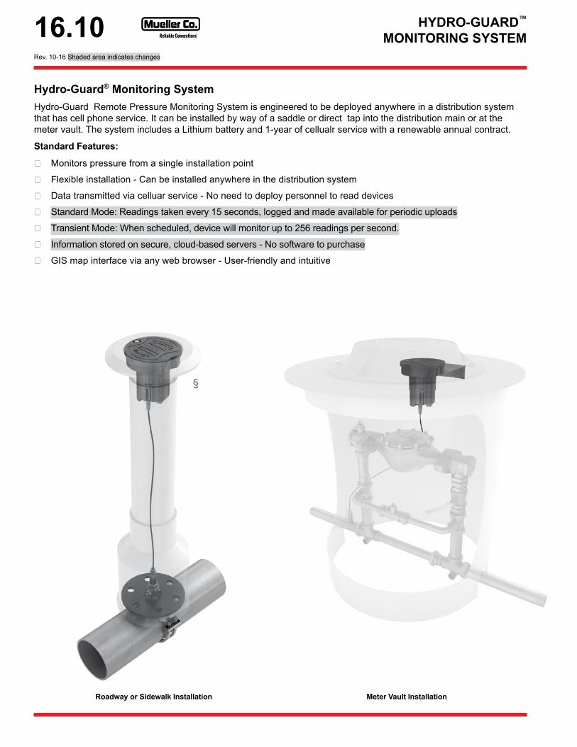
Hydro-Guard® Monitoring SystemHydro-Guard Remote Pressure Monitoring System is engineered to be deployed anywhere in a distribution system that has cell phone service. It can be installed by way of a saddle or direct tap into the distribution main or at the meter vault. The system includes a Lithium battery and 1-year of cellualr service with a renewable annual contract.
Standard Features:
❏ Monitors pressure from a single installation point
❏ Flexible installation - Can be installed anywhere in the distribution system
❏ Data transmitted via celluar service - No need to deploy personnel to read devices
❏ Standard Mode: Readings taken every 15 seconds, logged and made available for periodic uploads
❏ Transient Mode: When scheduled, device will monitor up to 256 readings per second.
❏ Information stored on secure, cloud-based servers - No software to purchase
❏ GIS map interface via any web browser - User-friendly and intuitive
Roadway or Sidewalk Installation Meter Vault Installation
§
HYDRO-GUARD™ MONITORING SYSTEM
Rev. 10-16 Shaded area indicates changes
16.10

Ordering GuideBelow is a simplified ordering guide to help select the options available. Please contact your Mueller sales representative for additional details and assistance.
HYDRO-GUARD™ MONITORING SYSTEM ORDERING GUIDE
STEP 1 - SELECT MODELSelection Code Other Select One
Pressure Monitoring System for installation in Vault or on Tank IWT1 ❏
Pressure Monitoring Sytem for Installation in Roadway IWT2 ❏
STEP 2 - SELECT TYPE of CELLULAR SERVICEGSM (AT&T) G - ❏
CDMA (Verizon) C - ❏
STEP 3 - SELECT CORPORATIONSTOP
IWT1 - No Corp. Included NC None ■IWT2 - Mueller 300 Ball Corp Included 45 3/4" ❏
STEP 4 - SELECT SERVICE SADDLE
IWT1 - No Saddle Included NOSADDLE None ■BR2B (3/4" cc) BR2B0474 4.74 - 5.32 - ❏
For use on Ductile / Cast Iron
BR2B0684 6.84 - 7.45 - ❏
BR2B0899 8.99 - 9.67 - ❏
BR2B1104 11.04 - 12.12 - ❏
BR2B1314 13.14 - 14.58 - ❏
BR2B1522 15.22 - 16.88 - ❏
BR2B1732 17.32 - 19.19 - ❏
BR2S (3/4" cc) BR2S0474 4.74 - 5.32 - ❏
For use on A-C, Cast Iron, & Ductile
BR2S0684 6.84 - 7.45 - ❏
BR2S0899 8.99 - 9.67 - ❏
BR2S1104 11.04 - 12.12 - ❏
BR2S1314 13.14 - 14.58 - ❏
BR2S1522 15.22 - 16.88 - ❏
BR2S1732 17.32 - 19.19 - ❏
BR2W (3/4" cc) BR2W1800 18.00 - 19.50 - ❏
For use on A-C, Cast Iron, & Ductile
BR2W2000 20.00 - 24.60 - ❏
BR2W2400 24.00 - 25.00 - ❏
STEP 5 - SELECT COMPOSITE VALVE BOX with 12" Cast Iron Upper Section
IWT1 - No Valve Box Included NOV - ■IWT2 - Mueller Valve Box 3' 03C 3-foot ❏
IWT2 - Mueller Valve Box 5' 05C 5-foot ❏
IWT2 - Mueller Valve Box 7' 07C 7-foot ❏
IWT2 - Mueller Valve Box 9' 09C 9-foot ❏
STEP 6 - SELECT SECURITY OPTIONLocking Lid LR Locking Nut ❏
OPTIONAL PARTSCast Iron Valve Box AJBV-4C Roadway Install ❏
Shaded area indicates change Rev. 10-16
16.11

ENCLOSURES
EnclosuresEnclosures are ideal for protecting valuable utility assets from the environment or vandalism.
Mueller offers a wide range of sizes, materials and options to meet a utility's need to cover a sample station, air release valve, or any other water or wastewater asset.
Standard Features:
❏ Plastic enclosures are UV and impact resistant polyethylene
❏ Metal enclosures are high-strength Aluminum, painted with Mueller® hydrant-quality finishes
❏ Powder-coated steel enclosures offer easy access to equipment and are available in a wide range of color options
❏ Below grade base for stability
❏ Most options offer 360° accessibility
❏ Corrosion resistant
❏ 1-year limited warranty
SGE140024CHA(not available in CA, AZ, NV, OR, & WA)
SGE080833DIV
SGE142435CHA00
Rev. 10-16 Shaded area indicates changes
16.12

STEP 1 - SELECT MODELType Code Select OneEnclosure SGE ■STEP 2 - SELECT ENCLOSURE STYLEPart Number Select One
ROUNDSGE180034CHA1 ❏SGE140024CHA1 ❏
SQUARECHA / StandardSGE070739CHASP ❏SGE101042CHASP ❏SGE121247CHASP ❏CHA / 316 Stainless SteelSGE070739CHA16 ❏SGE101042CHA16 ❏SGE121247CHA16 ❏DIVSGE080833DIV ❏SGE101029DIV ❏SGE121229DIV ❏MUE / Heavy Gauge Aluminum (Powder Coated)MUE080833PS ❏MUE101033PS ❏Custom Sized ❏
RECTANGLECHASGE142435CHA00 Standard Form ❏SGE142435CHA16 316 Stainless Steel ❏
DIVSGE163125DIVWO Without Insulation ❏SGE1633125DIVWI With Insulation ❏SGE203426DIVWO Without Insulation ❏SGE203426DIVWI With Insulation ❏
ROCK545781 For HG-2 / HG-4 ** ❏545782 For HG-5 ** ❏
OPTIONSItem Code Select OneTD Key (All DIV) HG-A2006 ❏Hex & Shoulder Bolt Lock Key Combo (All CHA except 14x24x35)
HG-A2023 ❏
P Key (CHA 14x24x35) HG-15113 ❏Curb Stop Key HG-20087 ❏ID Tag * (Any Model) HG-20033 ❏Vacuum Pump HG-A107 ❏
CHA Style EnclosuresShape Width Depth Height Part Number
Square
07" 07" 39" S G E 0 7 0 7 3 9 C H A
10" 10" 42" S G E 1 0 1 0 4 2 C H A
12" 12" 47" S G E 1 2 1 2 4 7 C H A
Rectangle 14" 24" 35" S G E 1 4 2 4 3 5 C H A
BL = Blue LG = Light Green DG = Dark GreenSS = Sand Sone* GR = Granite PR = Purple* Multi-colored faux stone appearance
ENCLOSURESORDERING INSTRUCTIONS
STEP 3 - SELECT COLORColor Code Select OneDIV & CHABlue BL ❏Light Green LG ❏Dark Green DG ❏CHA ONLYSand Stone SS ❏Granite GR ❏Purple PR ❏Tan TN ❏MUE ONLYDark Green DG ❏Water Blue BL ❏Brown BR ❏Purple PR ❏White WH ❏Black BK ❏
Ordering InstructionsTo order an Enclosure, simply choose the desired options from the chart below and contact your Mueller Sales Representative for pricing. ■ indicates option is included with the unit.
Part Numbering Example
1 - Not available in CA, AZ, NV, OR, & WA)
Shaded area indicates change Rev. 10-16
16.13

OPTIONAL EQUIPMENT &REPLACEMENT PARTS
Optional EquipmentType CodeHandheld Programmer for T2 Programmer Interface 545687
Security Kit (includes screw driver) for HG-1/HG-3 design (prior to 11/2015) HG-A103104
PSV - Portable Sample Valve (HG-1/HG-2/HG-5) HG-S116
Hydrant Wrench (HG-6) HG-A133Locking Device (HG-6) HG-A134Sample Port Upgrade for former HG-3 HG-S135Securing Screw Driver for former HG-1 & HG-3 (prior to 11/2015) HG-A103
Security Wrench HG-A104Portable Sample Valve HG-S116Portable Sample Valve - Stainless HG-S116BWinterizing Vacuum Pump for VAC Sample Stations HG-A107
Latching Solenoid for T2 Equipped Devices - 17" (HG1B/S, HG2, HG5) HG-S255B
Latching Solenoid for T2 Equipped Devices - 33" (HG6BA) HG-S256B
Latching Solenoid for T2 Equipped Devices - 50" (HG-1) HG-S257B
Replacement TBOS T-2 Controller Interface 545686HG-3 Ground Plate Sup-Assembly (prior to 11/2015) HG-S119
Low Pressure Relief Valve HG-S120HG-3 Diffuser Sub-Assembly (prior to 11/2015) HG-S121
HG-3 Riser Sub-Assembly (prior to 11/2015) HG-S122
HG-3/4 Bottom Plate Sub-Assembly HG-S123HG-1 Riser Assembly (since 11/2015) 546703HG-1 Above Grade Housing (since 11/2015) 546284
HG-1/HG-3 Decholorination Assembly (since 11/2015) 546519
Male Quick Connection HG-123104Male Quick Connection Cap HG-123105Femal Camlock - 2" HG-13101HG-1 NODE Bracket (since 11/2015) 546708HG-1/HG-3 Housing Diffusion Top (since 11/2015) 546514
HG-1/HG-3 Housing Diffusion Screen (since 11/2015) 546515
Hydrant Defender with HG-6 lock (red) HSZ0060010/HG-A134Hydrant Defender with HG-6 lock (yellow) HSZ0060014/HG-A134
Replacement Parts and Kits
Type CodeEPDM (HIT Valve) Diaphragm HG-16035HG-1 Control Valve Sub-Assembly (prior to 11/2015) HG-S101Banjo Connection Replacement Gasket HG-V102HG-1/HG-3 Ground Plate Gasket (prior to 11/2015) HG-01144HG-1/HG-3 Cap O-Ring Replacement (prior to 11/2015) HG-0119
HIT Valve with Flow Control HG-123100HIT Valve without Flow Control HG-123100BHG-1/HG-3 Cap Security Screws (prior to 11/2015) HG-13159HG-6 Cover Security Screws HG01126HG-3/HG-4 Low Pressure Relief Valve HG-S120Banjo Connection Female Sub-Assembly HG-S1252" HIT Valve Top Sub-Assembly HG-16037HG-1 Retrofit Kit for Conversion to RB TBOS T2 HG1-T2HG-2 Retrofit Kit for Conversion to RB TBOS T2 HG2-T2HG-3 Retrofit Kit for Conversion to RB TBOS T2 HG3-T2HG-4 Retrofit Kit for Conversion to RB TBOS T2 HG4-T2HG-5 Retrofit Kit for Conversion to RB TBOS T2 HG5-T2HG-6 Retrofit Kit for Conversion to RB TBOS T2 HG6-T2HG-1 Basic/S 1" Retrofit Kit for Conversion RB TBOS T2 HG1BS1-T2
HG-1 Basic/S 2" Retrofit Kit for Conversion RB TBOS T2 HG1BS2-T2
HG-1 Basic Retrofit Kit for Conversion RB TBOS T2 HG1BA-T2
Retrofit Kit for HG-1 HG1-NODERetrofit Kit for HG-2 HG2-NODERetrofit Kit for HG-6 HG6-NODERetrofit Kit for HG-1-Basic/A HG1BS-NODENODE Controller Sub-Assembly HG-5292Freeze Protection Adaptpr HG-FP108Hydrant Swivel Adaptor HG-16018Hex Lock Replacement Kit HG-A2009Thermal Control Valve Replacement HG-FP100Thermal Control Valve Complete Assembly Replacement Kit 546846KIT
Replacement TBOS T2 Adaptor & O-Ring (prior to 11/2015) 546110
HG-A103/A104 Hunter NODE withBermad Solenoid
HG-2 HG-123100 HG-A134 Handheld PN: 545687
Rev. 4-17 Shaded area indicates changes
16.14
Top Related