


Languages
Pages
Legal


BookID 124849_ChapID 11_Proof# 1 - 20/10/2008
Chapter 11 Polymer–Iron Oxide Based Magnetic Nanocomposites
Mrinal Pal and Abhijit De
Abstract The thrust to develop magnetic particles, both fundamentally and techno-logically, arose out of the necessity for application of this in many spheres of the human race. Physical and chemical properties of lower dimension (nanoscale) particles are very much different from their bulk counterpart. Magnetic nanocomposites depicted quite a few unique properties like very low as well as very high coercivity, superparamagnetism, blocking temperature etc., which opened up new vistas in this area. It was quite evident that iron oxide, in different phases and alloys formed the basic macroscopic magnetic material. In the past few decades it was clear that besides developing magnetic particles as a pure material, there arose a tremendous compulsion to probe into diversions for an inter disciplinary area engulfing chemical and biological sciences for the benefit of mankind. One such effort resulted in determining the compatibility of nano-scale magnetic particles (metal oxides, particularly iron oxide) with polymeric materials to form organic/inorganic composites. Amongst the many questions, which generated with time, a few have been typically selected and addressed in this chapter. This chapter primarily concentrates on ways to prepare (both chemical and physical processes), understand structural aspects, magnetic behavior, electrical and optical properties of polymer–iron oxide based magnetic nanocomposites. Some interesting applications are discussed at the end of the chapter.
Abbreviations CCD : Charge coupled device; CM : Ceramic method ; DTA: Differential thermal analysis ; FTIR: Fourier transform infrared ; GCR: Glass-ceramic route ; HEBM : High-energy ball milling ; IAA: Iron (III) tris (3-allylacety-lacetonate) ; IO: Iron oxide ; IS: Isomer shift ; KG: Kilo gauss ; MBE: Molecular beam epitaxy ; MER: Magnetite epoxy resins ; MF: Magnetic fluids ; MS: Mössbauer spectroscopy ; MW: Microwave ; MZF Manganese zinc ferrite ; nm: Nanometer ; NR Natural rubber ; NZF: Nickel zinc ferrite ; PEG: Polyethylene glycol ; PMAA: Poly-methacrylic acid ; PVA: Polyvinyl acetate ; PVB: Poly vinyl butyral ; RFC: Rubber ferrite composite ; SEM: Scanning electron micro-scopy ; SGM: Sol-gel method ; TEM: Transmission electron microscope ; UV:
L. Merhari (ed.), Hybrid Nanocomposites for Nanotechnology, 1DOI 10.1007/978-0-387-30428-1_11, © Springer Science + Business Media LLC 2009
1
2
3
4
5
6
7
8
9
10
11
12
13
14
15
16
17
18
19
20
21
22
23
24
25
26
27
28
29
3031
M. Pal and A. De (�) Department of Physics , Presidency College , Kolkata 700 073 , India e-mail: [email protected]
Merhari_Ch11.indd 1Merhari_Ch11.indd 1 10/25/2008 2:04:15 AM10/25/2008 2:04:15 AM

2 M. Pal and A. De
BookID 124849_ChapID 11_Proof# 1 - 20/10/2008
Ultra-violet ; VSM: Vibrating sample magnetometer ; XPS: X-ray photoelectron spectroscopy ; XRD: X-ray diffraction ; m m: Micrometer ; m -XRF: Micro-focus X-ray fluorescence ; E
a : Anisotropy energy ; E
z : Zeeman energy ; H
c : Coercive
force ; H eff
: Hyperfine field ; k : Boltzmann’s constant ; K : Anisotropy constant ; M
s : Saturation magnetization of individual domain ; M
sa : Saturation magnetiza-
tion of the assembly or assembled particles ; M r : Remanence magnetization ; T
B :
Blocking temperature ; T c : Curie temperature ; T
N : Néel temperature ; V : Volume ;
D : Quadrupole splitting ; b : Full width at half maximum (FWHM) ; l : X-ray wave-length ; t : Relaxation time ; m : Magnetic moment .
11.1 Retrospect and Motivation
Why study magnetism and run after magnetic materials? If ever we were to ask such a question the answer is naturally – nature! Yes, there is no doubt that it was none other than nature that was primarily responsible to give us such a ver-satile topic and provide us with the material. We may recall our grandfather talking, where/when a man lazing with a stick was stunned to find the metal-end of the stick stuck to a stone . This was later termed lodestone or magnetite. Going a step ahead/further, fine particles of magnetite having single domain structure, existing inside living cells or organisms, are also known to depict magnetotaxis (direction seeking) effect gover ning their movement guided by earth’s magnetic field. A strong technology driven motivation has been the guiding factor to exploit and enhance the properties in the area of high-density magnetic recording, ferrofluids, etc. Further tremendous impact on theoretical interests like, super-paramagnetism, large coercivity, quantum tunneling of magnetization and giant magnetoresistance has been realized. Yet another additional aspect is miniaturi-zation, which brings about convenience and economy. All throughout the devel-opment process of inorganic/organic magnetic materials the basic motivation was sheer compulsion for applications critical to human race which are technology related areas (communication, space science, etc.) and interdisciplinary avenues (drug delivery or target specific drugs for treatment for dreaded diseases like cancer). There are also some critical challenges to be met to encounter the ever-increasing problems threatening the human race.
11.2 Introduction to Magnetism
11.2.1 Brief Overview
The magnetic properties of solids generally originate from the motion or spin of electrons. Magnetic materials vary from one another depending on the differences
32
33
34
35
36
37
38
39
40
41
42
43
44
45
46
47
48
49
50
51
52
53
54
55
56
57
58
59
60
61
62
63
64
65
66
Merhari_Ch11.indd 2Merhari_Ch11.indd 2 10/25/2008 2:04:15 AM10/25/2008 2:04:15 AM
11 Polymer-Iron Oxide based magnetic Nanocomposites 3
BookID 124849_ChapID 11_Proof# 1 - 20/10/2008
in the spin of electrons and their mutual interaction with the other quantum factors. The magnetic behavior of materials can be classified into the following five major groups:
1. Diamagnetism 2. Paramagnetism 3. Ferromagnetism 4. Ferrimagnetism 5. Antiferromagnetism
Materials in the first two groups are those that exhibit no collective magnetic interactions and are not magnetically ordered. Materials in the last three groups exhibit a long-range magnetic order below a certain critical temperature. Ferromagnetic and ferrimagnetic materials are usually what we consider as being magnetic (i.e., behaving like iron). The remaining three are so weakly magnetic that they are usually thought of as “nonmagnetic.”
1. Diamagnetism Diamagnetism is a fundamental property of all matter, although it is usually very
weak. This is due to the non-cooperative behavior of the orbiting electrons when exposed to an applied magnetic field. Diamagnetic substances are composed of atoms, which have no net magnetic moments (i.e., all the orbital shells are filled and there are no unpaired electrons). However, when exposed to a field, a negative magnetization is produced and thus susceptibility is negative.
2. Paramagnetism In paramagnetic materials, some of the atoms or ions in the material have a net
magnetic moment due to unpaired electrons in a partially filled orbital. One of the most important atoms with unpaired electrons is iron. However, the individual magnetic moments do not interact magnetically, and like diamagnetism, the magne-tization is zero when the field is removed. In the presence of a field, a partial align-ment of the atomic magnetic moments in the direction of the field results in a net positive magnetization and positive susceptibility.
3. Ferromagnetism In ferromagnetic materials, the atomic moments exhibit very strong interactions.
Electronic exchange forces results in a parallel or anti-parallel alignment of atomic moments which produce these interactions. Exchange forces are very large, equiva-lent to a field of the order 1,000 Tesla, or approximately a 100 million times the strength of the earth’s magnetic field. The exchange force is a quantum mechanical phenomenon due to the relative orientation of the spins of two electrons. Ferromagnetic materials exhibit parallel alignment of moments resulting in large net magnetization even in the absence of a magnetic field. The elements Fe, Ni and Co and many of their alloys are typical ferromagnetic materials. Two distinct char-acteristics of ferromagnetic materials are their spontaneous magnetization and the existence of magnetic ordering temperature.
67
68
69
70
71
72
73
74
75
76
77
78
79
80
81
82
83
84
85
86
87
88
89
90
91
92
93
94
95
96
97
98
99
100
101
102
103
104
105
106
107
Merhari_Ch11.indd 3Merhari_Ch11.indd 3 10/25/2008 2:04:15 AM10/25/2008 2:04:15 AM
4 M. Pal and A. De
BookID 124849_ChapID 11_Proof# 1 - 20/10/2008
4. Ferrimagnetism In ionic compounds, such as oxides, more complex forms of magnetic ordering
can occur due to their crystal structure. One type of magnetic ordering is ferrimagnet-ism. In this case the magnetic structure is composed of two magnetic sub lattices (called A and B) separated by oxygen atom. The exchange interactions are mediated by oxygen anions. When this happens, the interactions are called indirect or super-exchange interactions. The strongest super-exchange interactions result in an anti-parallel alignment of spins between the A and B sub lattices. In ferrimagnets, the magnetic moments of the A and B sub lattices are not equal and result in a net mag-netic moment. Ferrimagnetism is therefore similar to ferromagnetism. It exhibits all the hallmarks of ferromagnetic behavior of spontaneous magnetization, Curie temperature, hysteresis and remanence. However, ferro- and ferrimagnets have different magnetic ordering.
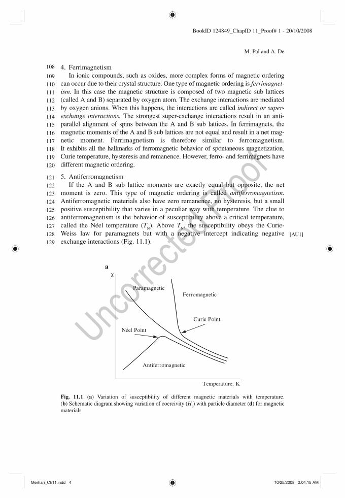
5. Antiferromagnetism If the A and B sub lattice moments are exactly equal but opposite, the net
moment is zero. This type of magnetic ordering is called antiferromagnetism. Antiferromagnetic materials also have zero remanence, no hysteresis, but a small positive susceptibility that varies in a peculiar way with temperature. The clue to antiferromagnetism is the behavior of susceptibility above a critical temperature, called the Néel temperature ( T
N ). Above T
N , the susceptibility obeys the Curie-
Weiss law for paramagnets but with a negative intercept indicating negative exchange interactions (Fig . 11.1 ).
[AU1]
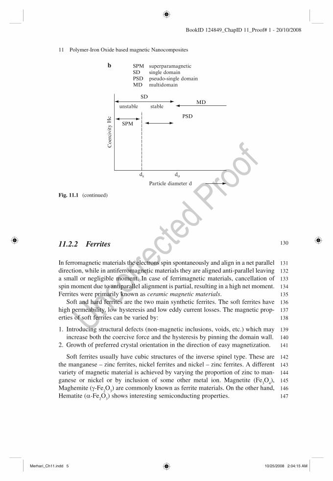
Fig. 11.1 ( a ) Variation of susceptibility of different magnetic materials with temperature. ( b ) Schematic diagram showing variation of coercivity ( H
c ) with particle diameter ( d ) for magnetic
materials
Antiferromagnetic
Curie Point
a
FerromagneticParamagnetic
Néel Point
Temperature, K
χ
108
109
110
111
112
113
114
115
116
117
118
119
120
121
122
123
124
125
126
127
128
129
Merhari_Ch11.indd 4Merhari_Ch11.indd 4 10/25/2008 2:04:15 AM10/25/2008 2:04:15 AM
11 Polymer-Iron Oxide based magnetic Nanocomposites 5
BookID 124849_ChapID 11_Proof# 1 - 20/10/2008
11.2.2 Ferrites
In ferromagnetic materials the electrons spin spontaneously and align in a net parallel direction, while in antiferromagnetic materials they are aligned anti-parallel leaving a small or negligible moment. In case of ferrimagnetic materials, cancellation of spin moment due to antiparallel alignment is partial, resulting in a high net moment. Ferrites were primarily known as ceramic magnetic materials .
Soft and hard ferrites are the two main synthetic ferrites. The soft ferrites have high permeability, low hysteresis and low eddy current losses. The magnetic prop-erties of soft ferrites can be varied by:
1. Introducing structural defects (non-magnetic inclusions, voids, etc.) which may increase both the coercive force and the hysteresis by pinning the domain wall.
2. Growth of preferred crystal orientation in the direction of easy magnetization.
Soft ferrites usually have cubic structures of the inverse spinel type. These are the manganese – zinc ferrites, nickel ferrites and nickel – zinc ferrites. A different variety of magnetic material is achieved by varying the proportion of zinc to man-ganese or nickel or by inclusion of some other metal ion. Magnetite (Fe
3 O
4 ),
Maghemite ( g -Fe 2 O
3 ) are commonly known as ferrite materials. On the other hand,
Hematite ( a -Fe 2 O
3 ) shows interesting semiconducting properties.
PSDSPM
MDstableunstable
ds do
Coe
rciv
ity
Hc
SPM superparamagneticSD single domainPSD pseudo-single domainMD multidomain
SD
Particle diameter d
b
Fig. 11.1 (continued)
130
131
132
133
134
135
136
137
138
139
140
141
142
143
144
145
146
147
Merhari_Ch11.indd 5Merhari_Ch11.indd 5 10/25/2008 2:04:15 AM10/25/2008 2:04:15 AM

6 M. Pal and A. De
BookID 124849_ChapID 11_Proof# 1 - 20/10/2008
11.2.3 Bulk vs. Fine Particles
The initial interest to work with fine particles and thin films of magnetic materials was kindled reading well-known texts [1, 2] . In contrast to macroscopic bulk fea-tures, fine particles of magnetic materials in pure form have shown some interesting features leading to fascinating technical applications. The spectrum of applications is tremendous which at one end we have high-efficiency motor, fridge magnet, and storage media devices and high frequency applications at the other. For such applica-tions both very soft (FeCuNbSiB) and very hard (NdFeB) magnetic materials are essential for nanocomposites.
Superparamagnetism and exchange anisotropy are prime aspects where it is assumed that the particles are single-domain and uniaxial. Usually uniaxial refers to direction for easy axis of magnetization. Consider an assembly of uniaxial, single-domain particles. The anisotropy energy density E for such a system is:
θ = K Sin 2 ( K is the anisotropy constant in erg/cm 3 , and θ is the angle between saturation magnetization M
s and easy axis). The energy barrier that must be over-
come before a particle can reverse its magnetization is: KV = ∆ E (ergs). The prod-uct of saturation magnetization of individual domain ( M
s ) and volume element of
fine particle system ( V ) gives the magnetic moment/movement of the system. When K = 0, each particle in a system has no anisotropy, and the moment/movement of each particle can have any direction as a result of the classical theory of paramag-netism. For such an assembly of magnetic particles (fine iron particles) in a non-magnetic matrix (solid mercury), the magnetization of such an assembly is:
( ),M n L am= (11.1)
where a = m H /kT and the saturation magnetization M sa = n m , where n is the number
of particles per unit volume of assembled particles and m is the magnetic moment per particle. Initial ( M
i ) and remanence ( M
r ) magnetizations are related with
relaxation time ( t ) as
r i exp( / ).M M t t= − (11.2)
The magnetization of fine-particle magnetic solids, M , is given by the Langevin equation,
sa/ coth( / / ),M M H kT kT Hm m= − (11.3)
where H is the field, T is the absolute temperature, m (= M s V ) is the magnetic
moment per particle, and k is the Boltzmann’s constant [3] . Hysteresis appears and superparamagnetism disappears when particles of a
certain size are cooled to a particular temperature, or when the particle size at constant temperature increases beyond a particular diameter D
P . This means that
the determination of critical values of temperature or size is highly fundamental.
148
149
150
151
152
153
154
155
156
157
158
159
160
161
162
163
164
165
166
167
168
169
170
171
172
173
174
175
176
177
178
179
180
181
182
183
184
Merhari_Ch11.indd 6Merhari_Ch11.indd 6 10/25/2008 2:04:15 AM10/25/2008 2:04:15 AM
11 Polymer-Iron Oxide based magnetic Nanocomposites 7
BookID 124849_ChapID 11_Proof# 1 - 20/10/2008
Initially spherical particles of iron of diameter about 50 Å dispersed in solid mercury at 200°K and 77°K depicted superparamagnetic nature. At 4.2°K the parti-cles in the assembly do not have sufficient thermal energy for complete thermal equilibrium with the applied field during the time required for experimentation.
An assembly of fine particles of cobalt, say spherical particle Co of diameter 68 Å and t of 0.1 s at room temperature, tries to reach thermal equilibrium ( M
r ) almost
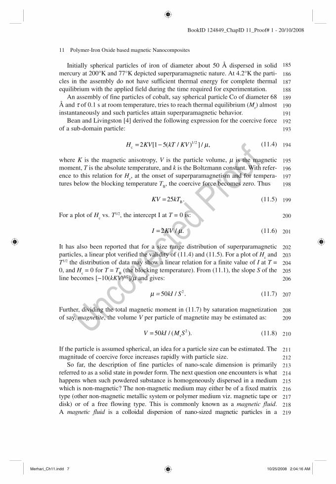
instantaneously and such particles attain superparamagnetic behavior. Bean and Livingston [4] derived the following expression for the coercive force
of a sub-domain particle:
1/2c 2 [1 5( / ) ] / ,H KV kT KV m= − (11.4)
where K is the magnetic anisotropy, V is the particle volume, m is the magnetic moment, T is the absolute temperature, and k is the Boltzmann constant. With refer-ence to this relation for H
c , at the onset of superparamagnetism and for tempera-
tures below the blocking temperature T B , the coercive force becomes zero. Thus
B25 .KV kT= (11.5)
For a plot of H c vs. T 1/2 , the intercept I at T = 0 is:
2 / .I KV m= (11.6)
It has also been reported that for a size range distribution of superparamagnetic particles, a linear plot verified the validity of (11.4) and (11.5). For a plot of H
c and
T 1/2 the distribution of data may show a linear relation for a finite value of I at T = 0, and H
c = 0 for T = T
B (the blocking temperature). From (11.1), the slope S of the
line becomes [−10( kKV ) 1/2 ]/ m and gives:
250 / .kI Sm = (11.7)
Further, dividing the total magnetic moment in (11.7) by saturation magnetization of say, magnetite , the volume V per particle of magnetite may be estimated as:
2s50 / ( ).V kI M S= (11.8)
If the particle is assumed spherical, an idea for a particle size can be estimated. The magnitude of coercive force increases rapidly with particle size.
So far, the description of fine particles of nano-scale dimension is primarily referred to as a solid state in powder form. The next question one encounters is what happens when such powdered substance is homogeneously dispersed in a medium which is non-magnetic? The non-magnetic medium may either be of a fixed matrix type (other non-magnetic metallic system or polymer medium viz. magnetic tape or disk) or of a free flowing type. This is commonly known as a magnetic fluid . A magnetic fluid is a colloidal dispersion of nano-sized magnetic particles in a
185
186
187
188
189
190
191
192
193
194
195
196
197
198
199
200
201
202
203
204
205
206
207
208
209
210
211
212
213
214
215
216
217
218
219
Merhari_Ch11.indd 7Merhari_Ch11.indd 7 10/25/2008 2:04:16 AM10/25/2008 2:04:16 AM
8 M. Pal and A. De
BookID 124849_ChapID 11_Proof# 1 - 20/10/2008
non-magnetic carrier. Non-magnetic materials could either be metallic for instance Hg systems [1] or any organic matrix compound. In a magnetic fluid, in contrast to bulk properties of magnetic materials in powder or solid state, the rotational freedom of the particles enables the magnetization process to be independent of particle ani-sotropy. So in ferrofluids the magnetization represents the degree of alignment of the magnetic moments of the particles. This is the Zeeman energy, E
z = m H , where m is
the magnetic moment of the particle and H the applied magnetic field. If a matrix is solidified in presence of an applied magnetic field, a magnetically textured sample is obtained which has particles of fixed orientation. In such a system, the Neel rota-tion of magnetic moments, away from the easy axis of the particle decides the in-field magnetization process. The applied magnetic field and the process temperature during sample preparation influence the statistical distribution of anisotropy axes. Basically, two types of dispersed systems have been of prime importance. Firstly, in a mono-dispersed system it was fundamental to estimate the difference between the normalized magnetization curves for magnetically textured samples and ferrofluids . Secondly, in a poly-dispersed system an increase in anisotropy energy ( E
a = KV ,
where K is the effective anisotropy constant and V = particle volume) is referred to resistance to magnetization . When E
a � E
z the difference between magnetization of
fluid and textured fluid is very small for a particular temperature. The grain size, in the free state or in thin film or in any other configuration, is
usually calculated using Scherrer’s equation [5]
),D k Cosl / (b q= (11.9)
where D is the grain size, l the X-ray wavelength, b (in radian) is the full width at half maximum (FWHM) of the peaks, θ the reflection angle and k is a constant of value ~1.
11.2.4 Thin Films
The term thin film refers to “down-scale” of bulk material, which is reached when the thickness of the material is equal to less than 1 m m. This means the surface prop-erty of the material is dominant compared to its bulk counterpart. Such geometrical configuration of any material is unable to stand by itself and necessarily needs a substrate on which it is grown or deposited and is able to arrive at a lower strain energy to form stable films. In certain special cases “stand alone films” may be developed, but their uses have been rather limited. The substrate may be amorphous or crystalline in nature. The sticking probability of the deposited film material on the substrate material depends on the lattice matching between them. For low sticking probability, films tend to peel off the substrate surface.
Thin films are grown using either a physical or a chemical process. Contamination and undesired oxidation are serious problems during the growth of thin films, which can be overcome using ultra-high vacuum techniques. Usual physical processes to
220
221
222
223
224
225
226
227
228
229
230
231
232
233
234
235
236
237
238
239
240
241
242
243
244
245
246
247
248
249
250
251
252
253
254
255
256
257
258
Merhari_Ch11.indd 8Merhari_Ch11.indd 8 10/25/2008 2:04:17 AM10/25/2008 2:04:17 AM
11 Polymer-Iron Oxide based magnetic Nanocomposites 9
BookID 124849_ChapID 11_Proof# 1 - 20/10/2008
grow thin films are sputtering, thermal evaporation, electron beam evaporation, molecular beam epitaxy (MBE), etc. MBE has the capability to grow films of thick-ness of a single atomic layer. Multilayer or sandwich structures are also possible to be grown in various configurations.
Under this section probably it may be more relevant to include the term film, which could engulf both thick and thin films. However, it will be discussed that inorganic oxides need an organic coating as holding or a support medium for very important applications.
As an ending note to this section, the magnetic materials are broadly classified as soft (easily magnetized) and hard (difficult to magnetize). “Soft” magnets (e.g., Ni/Fe alloy, Fe, etc.) have low magnetic coercive field (<10 Oe) and almost zero remanent magnetization. On the other hand, “hard” magnets (e.g., iron oxide doped with Co, CrO
2 , Fe particles, barium ferrite, etc.) have high magnetic coercive field
(>100 Oe) and significant remanent magnetization.
11.3 Preparation Methods
Some preparation methods for growing organic/inorganic magnetic nanocompos-ites are discussed below.
11.3.1 Chemical Methods
11.3.1.1 Co-precipitation Method
The process of co-precipitation deals with precipitation of multi-component or com-pound system in a matrix medium. Solid precipitates are formed and are filtered for a homogeneous matrix formation. A solution of inorganic or organic salt forms the co-precipitation agent. It is important that the essential compound be insoluble in the mother liquid. Mixing rate, pH, temperature, concentration, etc. are the main param-eters, which need to be regulated carefully [6] . After proper drying and subsequent annealing, nanostructure materials are obtained in the system. Lot of care must be taken to maintain homogeneity of the nanostructure material in the matrix medium.
11.3.1.2 Sol-Gel Method (SGM)
The sol-gel chemistry is based on the hydrolysis and condensation of alkoxides, M (OR)
z , where M z+ is a metal, and “R” an alkyl group (R = Me, Et,). Alkoxides are not
miscible with water so that a common solvent, usually the parent alcohol ROH, has to be used. The oxide network progressively grows from the solution, leading to the forma-tion of oligomers, oxopolymers, colloids (sols or gels), and finally a solid phase [7] .
259
260
261
262
263
264
265
266
267
268
269
270
271
272
273
274
275
276
277
278
279
280
281
282
283
284
285
286
287
288
289
290
291
Merhari_Ch11.indd 9Merhari_Ch11.indd 9 10/25/2008 2:04:18 AM10/25/2008 2:04:18 AM

10 M. Pal and A. De
BookID 124849_ChapID 11_Proof# 1 - 20/10/2008
Dispersions of colloids in liquids are basic to the formation of sols . Gel is short form of gelation implying growth and linking together of polymeric units to form a continuous network. It is interesting to note that at the very first stage of SGM an initial formation of amorphous network in the solution state precedes the process of crystal-lization. This is a distinct feature and in contrast to the crystallization process [8] . Mostly metal alkoxides, having a metal ion and alkyl group, are used as a starting compound. The process involves formation of an amorphous gel from solution through hydrolysis and poly-condensation reactions. Drying treatments in selected ambient are necessary as the obtained amorphous gel product contains sufficient amount of water and organic residues. Subsequent annealing of dehydrated gels is necessary to produce nanocrystalline materials. SGM favors low temperature processing. Large-scale application is rather discouraged as the parent metal alkoxides are highly expensive.
11.3.1.3 Solvent Evaporation Method
The process of solvent evaporation method is probably one of the simplest methods to select starting compounds, generate reaction pathways and treatment of end prod-ucts. It has tremendous potential for large-scale production, variety of combination compatibility and applications. In fact, solvent evaporation method may be diverted towards spray drying, rapid evaporation, flame pyrolysis, and thermolysis to develop nanosized mixed-oxide powders from a polymer matrix based precursor solution [9– 11] . In Sect. 5.1 a detailed description of this method has been discussed.
In the solvent evaporation method, the solvent can be retrieved in a closed system and can be made to use again, which is not the case under normal exhaust. Indeed, letting the solvent escape to the atmosphere is undesirable to both envi-ronment and economy.
11.3.1.4 Combustion Method
The two main aspects of the combustion method are externally induced and self-sustaining combustion synthesis. The self-sustaining combustion method is rapid and avoids formation of intermediate crystalline phases that require inter-diffusion for complete reaction.
11.3.2 Physical Methods
11.3.2.1 Conventional Ceramic Method
The ceramic method (CM) is one of the most primitive and well-proven methods to produce powder material. Primarily this process was used to develop ferrite materi-als even industrially. There are some typical steps followed for manufacture of polycrystalline ferrites in powder form [12] . CM begins with the usual weighing of
292
293
294
295
296
297
298
299
300
301
302
303
304
305
306
307
308
309
310
311
312
313
314
315
316
317
318
319
320
321
322
323
324
325
326
Merhari_Ch11.indd 10Merhari_Ch11.indd 10 10/25/2008 2:04:18 AM10/25/2008 2:04:18 AM

11 Polymer-Iron Oxide based magnetic Nanocomposites 11
BookID 124849_ChapID 11_Proof# 1 - 20/10/2008
raw materials. Then it has to be either dry mixing i.e., pressing or wet mixing i.e., filtering and drying of compounds, to get the product materials. Then pre-sintering is done, then crushing follows. The next step is dry mixing or wet milling, filtering and dry powdering. Then the obtained material is mixed with a binder or lubricant. Granulation of the material is done for homogeneous product formation. This is followed by die pressing and finally sintering to get the net product.
One of the advanced versions of CM is the glass-ceramic route (GCR). Glass–ceramics basically refers to controlled crystallization of appropriate glasses. Precipitation of different types of nanocrystalline phases in selected parent glass systems is performed using two-stage heat treatment programs. Heat treatment at nucleation and crystallization temperature is highly critical during formation of glass materials. Differential thermal analysis (DTA) provides both, the crystalline temperature and the glass transition temperature from which the nucleation temperature is estimated. Pal et al. [13, 14] reported that nanoparticles of certain compounds remained well protected within the glass matrix.
11.3.2.2 Sputtering
For the process of sputtering, a target material which may be composed of a single element or compound form is selected as an electrode in a vacuum chamber. The requirement of high to ultra-high vacuum of the deposition chamber reduces the probability for contamination. Gas (argon or krypton or a reactive gas by combining with proportions of hydrogen or oxygen) plasma is generated thereby creating a mix-ture of ions of high energy, accelerated and bombarded onto the target. Atoms and clusters, both neutral and ionic, are ejected from the target, which are essential to the formation of films on selected substrates placed at required position inside the chamber. The sputtering parameters like, plasma environment, its pressure, sputtering power, duration for film growth, substrate temperature regulate ionic movement and control the type of film material. Stavroyiannis et al. [15] could estimate the ratio of atoms to clusters or ions to neutrals produced, depending on the mass and energy of the pro-jectile ion and a variety of other experimental parameters. The process involving co-sputtering is more efficient for materials with low mutual solubility. In situ annealing of sputtered grown films has been known to control the material from being amor-phous or crystalline. One of the major drawbacks for sputtering is formation of clus-ters in the film material. However, for large scale production or in-line process for film growth sputtering has proved to be of immense potential.
11.3.2.3 Molecular Beam Epitaxy (MBE)
MBE is one of the most advanced processes to grow highly precise controlled layered films. However, ultrahigh vacuum conditions and stringent technological setup are critical during film growth. This is a technique in which epitaxial layers are grown on temperature controlled substrates by impinging molecular or atomic beams evapo-rated from effusion sources under ultrahigh vacuum conditions. Inoue et al. [16]
327
328
329
330
331
332
333
334
335
336
337
338
339
340
341
342
343
344
345
346
347
348
349
350
351
352
353
354
355
356
357
358
359
360
361
362
363
364
365
366
Merhari_Ch11.indd 11Merhari_Ch11.indd 11 10/25/2008 2:04:18 AM10/25/2008 2:04:18 AM

12 M. Pal and A. De
BookID 124849_ChapID 11_Proof# 1 - 20/10/2008
reported that in contrast to conventional evaporation techniques the beam intensities of each source and the substrate temperature in MBE can be separately controlled to achieve epitaxial growth depending on the selection of substrate material.
11.3.2.4 Melt Spinning
Preparation of two-phase magnetic materials involving coupling of hard and soft magnetic materials have been possible employing the process of melt spinning. Alloy ingots are prepared selecting starting materials of about three to five elements. Combinations of such starting materials are usually heated by employing arc melting in some inert atmosphere. The alloy ingots are crushed into small pieces which are transferred to quartz crucibles with a nozzle diameter less than one millimeter. Melt spinning amorphous ribbon samples of various thicknesses are prepared using single roll melt spinning equipment with a copper roll in an inert atmosphere. Ping and Hono [17] reported amorphous samples which were sealed in an evacuated quartz tube and annealed for different time periods. The process of melts spinning offered minimum interface contamination and favored production of porosity free materials. Altering the annealing conditions controlled the grain sizes inside the samples. Melt spinning is a viable process for large-scale production of required material.
11.3.2.5 Mechanical Alloying
Mechanical alloying or mechanical milling or high-energy ball milling (HEBM) is usu-ally employed to prepare nanocrystalline alloys. The starting powder material is intro-duced in a vial containing a number of milling balls and subjected to vigorous shaking. Such violent action brings about energy transfer to the powdered particles in the mills by virtue of shearing action or impact of the high velocity balls with the powder. This leads to the formation of nanostructured materials. The dimension and structure of nanoparti-cles in the powdered material depends on parameters like milling speed, type, size, size distribution of balls, ball to powder weight ratio, milling atmosphere, etc. [18] . The prime hindrance of HEBM is contamination from the ball material. HEBM is one of the present commercial technological processes for large-scale production of material.
11.4 Iron Oxide (IO)
11.4.1 Pure Phase
Iron ferrite is probably the oldest magnetic material known to mankind. Magnetite (Fe
3 O
4 ), also known as ferrous ferrite, has a cubic structure. Their general form is
MO. Fe 2 O
3 , where M is a divalent metal ion like Mn, Fe, Ni, Co, Mg, etc.
Maghemite ( g -Fe 2 O
3 ) is ferrimagnetic in nature, has a cubic structure or spinel
crystal structure, made by oxidizing magnetite:
367
368
369
370
371
372
373
374
375
376
377
378
379
380
381
382
383
384
385
386
387
388
389
390
391
392
393
394
395
396
397
398
399
400
401
Merhari_Ch11.indd 12Merhari_Ch11.indd 12 10/25/2008 2:04:18 AM10/25/2008 2:04:18 AM
11 Polymer-Iron Oxide based magnetic Nanocomposites 13
BookID 124849_ChapID 11_Proof# 1 - 20/10/2008
3 4 2 2 32 Fe O ½ O 3Fe O+ →
Maghemite is unstable and transforms to hematite ( a -Fe 2 O
3 ) on heating above 673
K in air. The magnetic ions (Fe 3+ ) in g -Fe 2 O
3 are identical in nature and ferrimagnetism
is due to unequal distribution of such ions in the available sites. The tetragonal cell of g -Fe
2 O
3 is obtained as conversion from Fe
3 O
4 . A unit cell of Fe
3 O
4 contains eight
molecules. Maghemite can be considered as a Fe (II)-deficient magnetite. The structure of g -Fe
2 O
3 has inverse spinel structure and is represented as Fe 3+ [Fe 3+
40/3
1/8 ] O
32 ,
where represents the vacancy site present in the lattice. The Fe 3+ ions outside the square bracket represent tetrahedral position and the Fe 3+ ions inside the square bracket represent the octahedral position. The structure is based around a face centered cubic array of oxygen atoms with the cations filling either the tetrahedral or octahedral inter-stices within this array. There are 16 (out of 32) occupied octahedral sites and 8 (out of 64) occupied tetrahedral sites in the unit cell g -Fe
2 O
3 . Thus a molecule of g -Fe
2 O
3
corresponding to a unit cell can be calculated to have a net moment of 2.5 m B .
The naturally occurring maghemite usually forms by weathering or low-tempera-ture oxidation of spinels containing ferrous iron, commonly magnetic or titanium magnetite. They exist as widespread yellow pigment in sediments. Encyclopaedia Britannica says that maghemite exhibits strong magnetism and remanence. Its struc-ture is isometric, of defective spinel form, and somewhat iron-deficient. It is metastable with respect to hematite and forms a continuous metastable solid with magnetite.
Usually g -Fe 2 O
3 is synthesized from a -goethite. The process of transformation
of a -goethite to g -Fe 2 O
3 is represented as:
2 3 3 4 2 3- FeOOH - Fe O Fe O - Fe Oα → α → → γ
Compounds like lepidrocite [ g -FeO (OH)] when treated with pyridine and oxidized for long hours give complete conversion to g -Fe
2 O
3 having nanosized particle
dimension (Venkataraman 2001 ). In some cases the conversion of Fe(OH) 2 to
g -Fe 2 O
3 gets accelerated by heating and may take place through intermediates such
as FeO(OH) and Fe 3 O
4 [19] .
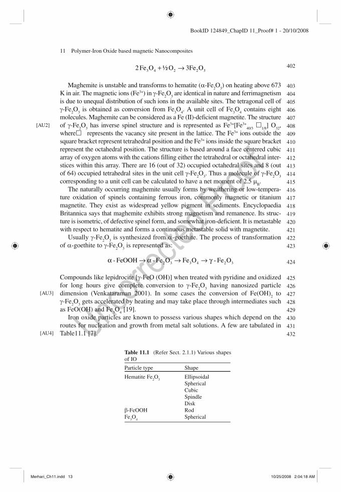
Iron oxide particles are known to possess various shapes which depend on the routes for nucleation and growth from metal salt solutions. A few are tabulated in Table 11.1 [7] .
[AU2]
[AU3]
[AU4]
Table 11.1 (Refer Sect. 2.1.1) Various shapes of IO
Particle type Shape
Hematite Fe 2 O
3 Ellipsoidal
Spherical Cubic Spindle Disk
b -FeOOH Rod Fe
3 O
4 Spherical
402
403
404
405
406
407
408
409
410
411
412
413
414
415
416
417
418
419
420
421
422
423
424
425
426
427
428
429
430
431
432
Merhari_Ch11.indd 13Merhari_Ch11.indd 13 10/25/2008 2:04:18 AM10/25/2008 2:04:18 AM
14 M. Pal and A. De
BookID 124849_ChapID 11_Proof# 1 - 20/10/2008
11.4.2 Composite
Ni 1–x
Zn x Fe
2 O
4 (NZF) and Mn
1–x Zn
x Fe
2 O
4 (MZF) are among zinc-based ferrite com-
posites that have attracted attention [20– 22] . Iron oxide was alloyed either with other ferromagnetic/ferrimagnetic or divalent elements. More details relevant to this compound will be discussed in the next section.
11.5 Metal Oxide Polymer Magnetic Nanocomposites
Metal salts (MX) when dissolved in an aqueous medium dissociate into ions in the solution. The negative charge of anions X z− balances the positive charge of the atom M z+ [7] . When a polymer structure provider (polyvinyl alcohol – PVA, polyvinyl acetate, polyethylene glycol, etc.) is added to the metal compound, particularly nitrates, following the solution evaporation process, two phenomena are known to occur. Firstly, during addition of optimum amount of the polymer material to the mixed metal nitrate solution, the polar groups of the long chain polymer play a wrapping and covering role for the cations in the solution. A mutual contact between cations is restricted, which limits the growth of cations in size. Thus the metal ions remain uniformly distributed in the viscous liquid during evaporation. Secondly, complete evaporation of PVA gives out carbonaceous material, which provides heat through combustion for the formation of fine single-phase ferrite powders at a relatively low external temperature. Pramanik and Pathak [10] reported addition of urea to a mixture of metal compound, appropriate solvent, and polymer structure provider . It was observed that urea acted as a retardant which arrested the crystallization of the precursor powder during complete evaporation of the polymer structure provider added solution.
PVA is one of the most widely used polymers to support formation of metal oxide polymer nanocomposites. PVA of general structure (–C
2 H
4 O)
n has the following char-
acteristics: crystal system – monoclinic, space groupP2 1 /m-C
2h 2 , lattice constants – a =
7.81 Å, b = 2.25 Å, c = 5.51 Å and b = 91.7°, number of chains per unit cell – N = 2, molecular conformation – planar zigzag, and crystal density of 1.35 g/cc. PVA pre-pared from polyvinyl acetate has an atactic structure i.e., at-PVA. PVA prepared from isotactic -polyvinyl ethers by low temperature polymerization has isotactic structure i.e., it-PVA . Polarized infrared (IR) spectrum of it-PVA shows parallel dichroism bands at 3,340 and 1,460 cm −1 , while for at-PVA it is observed at 1,141 and 909 cm −1 [23] .
11.5.1 Polymer Coated Magnetic Nanoparticles
To arrive at the formation of polymer coated magnetic nanoparticles, selection of parent compounds, and generation of precursor materials with follows up routes for final product formation are highly critical.
433
434
435
436
437
438
439
440
441
442
443
444
445
446
447
448
449
450
451
452
453
454
455
456
457
458
459
460
461
462
463
464
465
466
467
468
Merhari_Ch11.indd 14Merhari_Ch11.indd 14 10/25/2008 2:04:18 AM10/25/2008 2:04:18 AM

11 Polymer-Iron Oxide based magnetic Nanocomposites 15
BookID 124849_ChapID 11_Proof# 1 - 20/10/2008
Recalling the Sect. 3.1.3 for solvent evaporation method , metal nitrates or equivalents may be selected as solute and hydrolyzed in aqueous medium to form a precursor solution. Let us concentrate on iron III nitrate (Fe(NO)
3 ·9H
2 O) as a
solute and 2methoxy-ethanol (CH 3 –O–CH
2 –CH
2 –OH) as the solvent. Any potential
reaction involving 2methoxy-ethanol (2ME) is not very likely, as the solution tem-perature was not raised above 443 K. It could be simple boiling and evaporation of the solvent rather than its decomposition. In general the reaction may be as:
⋅ → + +3 2 2 2[M(NO) 9H O] M O H O NOx yX z m
This means a combination of iron III nitrate (I3N) with a solvent such as 2methoxy-ethanol and heating to dryness in air gives probable oxides of iron. The freshly prepared samples (Table 11.2 ) do not show any presence of oxy-hydrides but the tendency of their formation cannot be restricted if kept exposed to air. The process to grow iron oxide by the solvent evaporation method is briefly described below. Iron III nitrate is highly soluble in 2methoxy-ethanol giving a characteristic red color to the solution. The solutions were prepared as weight/volume (w/v) ratio; i.e., 1 mg iron III nitrate in 1 ml 2methoxy-ethanol giving 1:1 (w/v) solution (Table 11.2 ). They were transferred to crucibles containing 1 mg PVA in 10 ml-distilled water at room temperature. The crucibles were mounted on the hotplate, in the air, with constant stirring of the solution. The temperature of the hotplate was gradually raised in stages. At about 333 K bubbles appeared and at 353 K the solution began to boil. The temperature was kept constant to maintain the bubbling process till the solution became viscous. The heating process was continued to the final tempera-tures ranging from 393 K to 443 K for about 2 h till the viscous solution became a dry powdery mass. For rapid evaporation the solution temperature can be increased, but it was observed that increased vigorous bubbling led to the loss of the material. The end product was dry powdery mass, which easily crumpled to a homogeneous form. No heavy granules or coagulated particles were observed.
In the process of solvent evaporation method PVA having a molecular weight of about 125,000 to higher values were used [10, 11] . PVA [general structure (–C
2 H
4 O)
n ] having a degree of polymerization of 1,700 corresponding to a molecu-
lar weight 44 × 1,700 = 74,800 were tried for the same process [9] . Yogo et al. [24] could hydrolyse Iron (III) tris (3-allylacetylacetonate) [IAA] to
form antiferrimagnetic a -Fe 2 O
3 . This was possible, as Fe in IAA exists in trivalent
Table 11.2 (Refer Sect. 5.1): A set of powder samples grown by using the proc-ess of solvent evaporation method
Code Preparation conditions Product nature
Sample 1 1:5(w/v) I3N in 2ME, 443 K Amorphous Sample 2 1:1(w/v) I3N in 2ME, 443 K Crystalline ( g -Fe
2 O
3 & Fe
3 O
4 )
Sample 3 1:1(w/v) I3N in 2ME, 393 K Crystalline ( g -Fe 2 O
3 )
Sample 4 1:1(w/v) I3N in 2ME, 443 K + 10%(w/v) sucrose solution
Crystalline ( g -Fe 2 O
3 , Fe
3 O
4 &
a -Fe 2 O
3 )
469
470
471
472
473
474
475
476
477
478
479
480
481
482
483
484
485
486
487
488
489
490
491
492
493
494
495
496
497
498
499
500
501
Merhari_Ch11.indd 15Merhari_Ch11.indd 15 10/25/2008 2:04:18 AM10/25/2008 2:04:18 AM
16 M. Pal and A. De
BookID 124849_ChapID 11_Proof# 1 - 20/10/2008
form. Polymerization of IAA at 373 K for 42 h in ethanol resulted to IAA oligomer. An oligomer is a polymer having comparatively few monomer units in the mole-cule. IAA oligomer, which has good solubility in ethanol, hydrolyzes in hydrazine for conversion of Fe (III) to Fe (II). Ferrimagnetic iron oxide, having spinel oxide, resulted to IAA when the molar ratio was above 4 in the hydrolysis process.
In an interesting effort to develop iron oxide (IO) powders from organic based compounds, amorphous iron oxide was produced by the pyrolysis of iron pentacar-bonyl [Fe(CO)
5 ] in a modified domestic microwave (MW) oven in refluxing chlo-
robenzene as a solvent under air [25] . Initially a solution mixture of iron pentacarbonyl and cholorobenzene was irradiated and refluxed simultaneously for 20 min with 90% of the MW instruments power (90% meant that on/off irradiation cycles were in the ratio 9/1). The process of MW irradiation raised the temperature of the solution mixture. Cooling of the mixture was followed by centrifuge with chlorobenzene and pentane, and drying under vacuum (approximately 308 K and 15 mm Hg) for 24 h. When such iron oxide powders, amorphous Fe
2 O
3 , were sub-
jected to a heating process at 773 K under vacuum the final product was hematite. Palchik et al. [25] employed differential scanning calorimetry (DSC) using nitro-
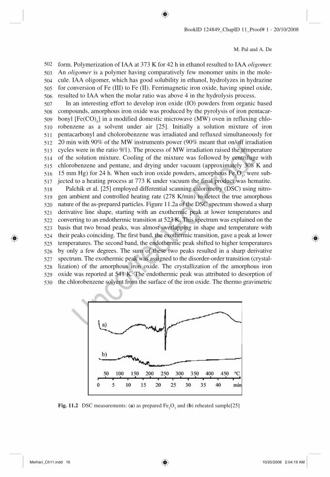
gen ambient and controlled heating rate (278 K/min) to detect the true amorphous nature of the as-prepared particles. Figure 11.2a of the DSC spectrum showed a sharp derivative line shape, starting with an exothermic peak at lower temperatures and converting to an endothermic transition at 523 K. This spectrum was explained on the basis that two broad peaks, was almost overlapping in shape and temperature with their peaks coinciding. The first band, the exothermic transition, gave a peak at lower temperatures. The second band, the endothermic peak shifted to higher temperatures by only a few degrees. The sum of these two peaks resulted in a sharp derivative spectrum. The exothermic peak was assigned to the disorder-order transition (crystal-lization) of the amorphous iron oxide. The crystallization of the amorphous iron oxide was reported at 541 K. The endothermic peak was attributed to desorption of the chlorobenzene solvent from the surface of the iron oxide. The thermo gravimetric
Fig. 11.2 DSC measurements: ( a ) as prepared Fe 2 O
3 and ( b ) reheated sample [25]
502
503
504
505
506
507
508
509
510
511
512
513
514
515
516
517
518
519
520
521
522
523
524
525
526
527
528
529
530
Merhari_Ch11.indd 16Merhari_Ch11.indd 16 10/25/2008 2:04:19 AM10/25/2008 2:04:19 AM

11 Polymer-Iron Oxide based magnetic Nanocomposites 17
BookID 124849_ChapID 11_Proof# 1 - 20/10/2008
analysis (TGA) spectrum supported the existence of the endothermic peak and attributed it to desorption of the material from the surface. On cooling the DSC-heated sample and reheating, a flat line was detected (Fig. 11.2b ).The absence of any characteristic peak for reheating process indicated that the as-prepared sample was truly amorphous and not X-ray amorphous. The exothermic peak at 516 K was interpreted as the amorphous-crystalline transition.
11.5.1.1 Structural Aspects
The foremost work to develop any material pertains to its basic structure. No doubt, the most well proven X-ray diffraction (XRD) of the polymer based powdered fer-rites (metal oxides) were performed to probe the phase (amorphous or crystalline or biphasic) existing in the material [9, 10, 25– 29] .
Initially, one may commence with a very simple route to form hybrid organic–inorganic magnetic nanocomposites. Considering the case for solution evaporation method it was observed that very less proportions of iron III nitrate in solution state (under heavy dilution) led to the formation of scanty precursors (Sample1 in Table 11.2 ) [9] . This probably caused incomplete network structure in solid state and generated amorphous structured material. At a higher amount of solute in solution phase and maintaining a drying temperature of 393–453 K resulted in crystalline powdered materials. For 1:1 (weight/volume) iron III nitrate in 2ME and drying temperature of 393 K the powdered material (Sample 3) showed XRD peaks at 2 θ = 30°, 35.2°, 43.2°, 54°, and 63.2°C corresponding to (220), (311), (400), (422) and (440) respectively. All such crystallographic planes confirm the presence of almost pure phase of g -Fe
2 O
3 . At 2 θ = 54° the situation is a bit tricky. This is because it
refers to both (511) (2 = 54.8, [28] and (422) (2 θ = 53.8°, [10] corresponding to Fe
3 O
4 and g -Fe
2 O
3 respectively. However, such a situation is not unlikely. Both
g -Fe (III) 2 O
3 and Fe
3 O
4 (Fe (III) [Fe (II) Fe (III) ]O
4 ) belong to the spinel structure and have
the lattice constants of 834 and 839 pm, respectively. Therefore, the exact phase is
Table 11.3 (Refer Sect. 5.1.1) – crystallographic planes and phases of IO from refer-ences – XRD analysis – [25– 29]
Maghemite Magnetite Hematite
G -Fe 2 O
3 Fe
3 O
4 a -Fe
2 O
3
2 θ (°) (hkl) 2 θ (°) (hkl) 2 θ (°) (hkl) 30.4 (220) 24.4 (012) 35.6 (311) 35.2 (311) 33.2 (104) 37.3 (222) 38.2 (222) 36.0 (110) 43.4 (400) 44.5 (400) 38.9 (113) 53.8 (422) 48.6 (024) 57.4 (511) 54.8 (511) 54.3 (116) 63.0 (440) 64.8 (531) 57.7 (018) 74.4 (533) 61.1 (214)
531
532
533
534
535
536
537
538
539
540
541
542
543
544
545
546
547
548
549
550
551
552
553
554
555
556
557
Merhari_Ch11.indd 17Merhari_Ch11.indd 17 10/25/2008 2:04:19 AM10/25/2008 2:04:19 AM

18 M. Pal and A. De
BookID 124849_ChapID 11_Proof# 1 - 20/10/2008
not determined by XRD (Table 11.3 ). Usually, fine particles reveal a smaller value of saturation magnetization compared with that of bulk. Under such circumstances existence of both phases may be declared. For a particular sample the relative peak heights (Table 11.4 ) were estimated from the peak intensities, which were normal-ized with respect to the domin ant crystallographic plane. This has been done to understand crystallographic plane growth conditions. Sample 2 was prepared at a higher temperature of 443 K and was found to possess a mixed phase of both g -Fe
2 O
3 and Fe
3 O
4 crystalline peaks (Table 11.2 and 11.4 ). A sample was tried
(Sample 4) by including sucrose solution as suggested by Pramanik and Pathak [10] . It was observed that this sample (Sample 4) primarily had crystalline peaks corresponding to a -Fe
2 O
3 along with the dominant (311) peak of g -Fe
2 O
3 . A com-
parison of peak positions with other references may not be always conclusive (Table 11.5 ). However, standard XRD peaks confirm the peak positions declared in the table for low molecular weight polymer based iron oxide. Figure 11.3 is sup-portive of the difference between Maghemite – C and Hematite XRD peak posi-tions [27] . Samples prepared with the addition of sucrose to the parent solution during their growth provided higher energy routes for chemical reaction. As a result, Fe
3 O
4 and g -Fe
2 O
3 got converted to a -Fe
2 O
3 at higher temperature. The main
purpose to grow phases of pure iron oxide, by solvent evaporation, was to under-stand the conditions favoring formation of maghemite or hematite or magnetite
Some more processes are discussed to form a comparative study and develop a complete picture for structure formation in hybrid magnetic nanocomposites. Venkatraman et al. [29] showed conversion of a -Fe
2 O
3 to g -Fe
2 O
3 in presence of
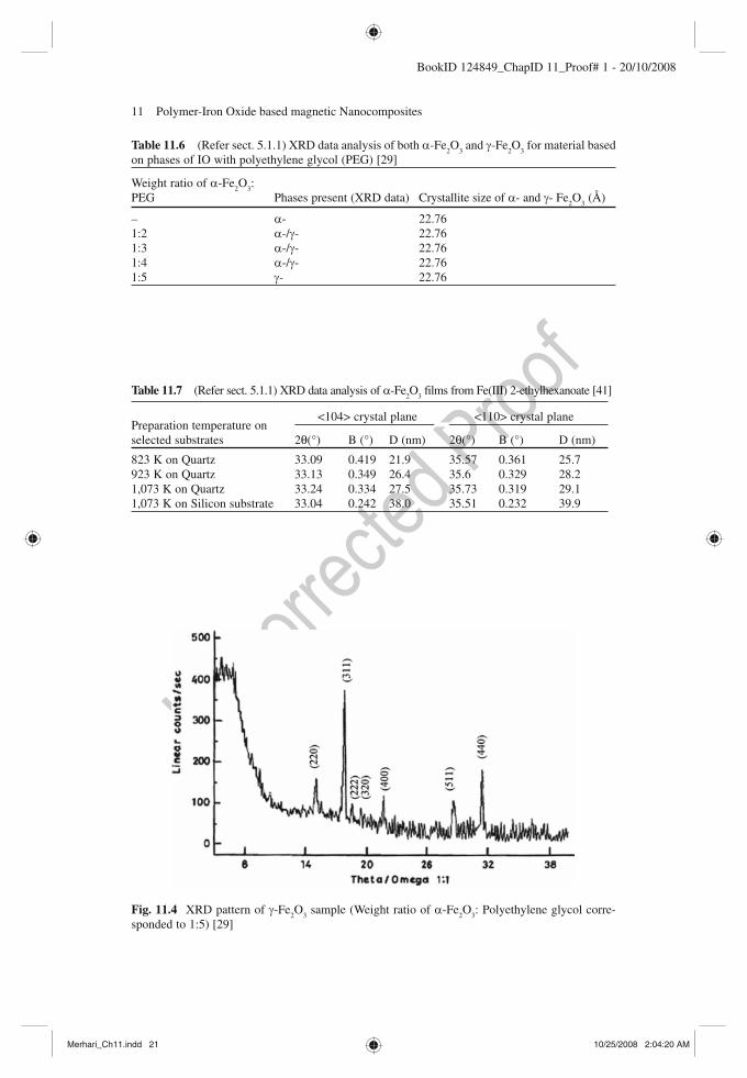
polyethylene glycol (PEG) in different weight ratios (Tables 11.6 and 11.7 ). For a comparison the relative peak heights were calculated from their data for sample giving pure g -Fe
2 O
3 . The most dominant crystallographic peak was at (311). The
normalized value of other peaks at (440), (220), (511), (400), (222) and (320) were 0.68, 0.27, 0.25, 0.21, 0.11 and 0.07 respectively (Fig. 11.4 )
Jungk and Feldmann [27] used the polyol method to obtain iron oxide particles which were isolated by centrifugation. During the synthesis process, g -Fe
2 O
3 began
to form at a temperature of 453 K indicating that the polyol medium was sufficient to produce the pure oxide instead of a hydroxide. A characteristic brownish red color confirmed g -Fe
2 O
3 . However, at a higher temperature of 523 K the material
transformed to a -Fe 2 O
3 giving a red colored powder (Fig. 11.3 ).
By now it is well known that processes involving higher heating profiles or stages favored a high degree of crystalline materials. In one of such cases, Pramanik and Pathak [10] reported XRD of NiFe
2 O
4 , CoFe
2 O
4 and ZnFe
2 O
4 precursor pow-
ders, prepared in the presence of urea with varying calcinations, temperature and time. The virgin samples prepared at lower temperatures were amorphous. Heating samples at 723 K (for 2 h) led to the formation of crystalline peaks at (311) and (400). Continued heating at 723 K (for 24 h) caused a slight improvement to the peak formations. Further rising/raising it to a higher temperature of 873 K (for 2 h) had a remarkable improvement of crystalline structure giving rise to peaks at (311), (220), (400), (422), (440) and (511). The growth of crystallinity in the precursor powders enhanced after thermal decomposition at 723 K and higher temperature
558
559
560
561
562
563
564
565
566
567
568
569
570
571
572
573
574
575
576
577
578
579
580
581
582
583
584
585
586
587
588
589
590
591
592
593
594
595
596
597
598
599
600
601
602
Merhari_Ch11.indd 18Merhari_Ch11.indd 18 10/25/2008 2:04:19 AM10/25/2008 2:04:19 AM

11 Polymer-Iron Oxide based magnetic Nanocomposites 19
BookID 124849_ChapID 11_Proof# 1 - 20/10/2008
Tabl
e 11
.4
(Ref
er S
ect.
11.5
.1.1
) X
RD
ana
lysi
s fo
r lo
w m
olec
ular
wei
ght p
olym
er b
ased
IO
[9]
Sam
ple
num
ber
2 Sa
mpl
e nu
mbe
r 3
Sam
ple
num
ber
4
2 θ (
°)
(hkl
) pl
ane
Phas
e R
elat
ive
Peak
H
eigh
t*
2 θ (
°)
(hkl
) pl
ane
Phas
e R
elat
ive
Peak
H
eigh
t*
2 θ(
°)
(hkl
) pl
ane
Phas
e R
elat
ive
Peak
H
eigh
t*
– –
– –
– –
– –
19.6
–
– 0.
18
30
(220
) g -
Fe 2 O
3 0.
3 30
(2
20)
g -Fe
2 O 3
0.33
30
(2
20)
g -Fe
2 O 3
0.26
35
.6
(311
) g -
Fe 2 O
3 1.
0 35
.2
(311
) g -
Fe 2 O
3 1.
0 35
.6
(311
) g -
Fe 2 O
3 1.
0 44
.8
(400
) Fe
3 O 4
0.35
43
.2
(400
) g -
Fe 2 O
3 0.
26
48.8
(0
24)
a -F
e 2 O 3
0.26
54
(5
11)
Or
(422
) Fe
3 O 4
Or
g -Fe
2 O 3
0.24
54
(5
11)
Or
(422
) Fe
3 O 4
Or
g -Fe
2 O 3
0.21
54
(1
16)
a -F
e 2 O 3
0.12
62.8
(4
40)
g -Fe
2 O 3
0.61
63
.2
(440
) g -
Fe2O
3 0.
3 57
.2
(511
) g -
Fe 2 O
3 0.
2 64
.8
(531
) Fe
3 O 4
0.24
62
.8
(531
) Fe
3 O 4
0.55
75
.6
– –
0.15
64
.8
(533
) Fe
3 O 4
0.19
73
.2
– –
0.15
Merhari_Ch11.indd 19Merhari_Ch11.indd 19 10/25/2008 2:04:19 AM10/25/2008 2:04:19 AM

BookID 124849_ChapID 11_Proof# 1 - 20/10/2008
Table 11.5 (Refer sect. 5.1.1) – XRD data analysis (measured values of 2 θ , B (FWHM) for polymer coated IO) (311) & (440) planes [9] )
(311) – g -Fe 2 O
3
Code 2θ (°) B (°) D (nm) Sample 2 35.64 0.5443 34.06 Sample 3 35.63 0.609 30.45 Sample 4 35.59 0.6141 30.18 (440) – g -Fe
2 O
3
Code 2θ (°) B (°) D (nm) Sample 2 62.83 0.6434 32.14 Sample 3 62.95 0.7159 28.9
Fig. 11.3 ( a ) XRD of Fe 2 O
3 particles after preparation, ICDD reference 39-1346, Maghemite-C,
synthetic and ( b ) after heating to 523 K (ICDD reference 33-0664, Hematite, synthetic) [27]
Merhari_Ch11.indd 20Merhari_Ch11.indd 20 10/25/2008 2:04:20 AM10/25/2008 2:04:20 AM
11 Polymer-Iron Oxide based magnetic Nanocomposites 21
BookID 124849_ChapID 11_Proof# 1 - 20/10/2008
Table 11.6 (Refer sect. 5.1.1) XRD data analysis of both a -Fe 2 O
3 and g -Fe
2 O
3 for material based
on phases of IO with polyethylene glycol (PEG) [29]
Weight ratio of a -Fe 2 O
3 :
PEG Phases present (XRD data) Crystallite size of a - and g - Fe 2 O
3 (Å)
– a - 22.76 1:2 a -/ g - 22.76 1:3 a -/ g - 22.76 1:4 a -/ g - 22.76 1:5 g - 22.76
Table 11.7 (Refer sect. 5.1.1) XRD data analysis of a -Fe 2 O
3 films from Fe(III) 2-ethylhexanoate [41]
Preparation temperature on selected substrates
<104> crystal plane <110> crystal plane
2θ(°) B (°) D (nm) 2θ(°) B (°) D (nm)
823 K on Quartz 33.09 0.419 21.9 35.57 0.361 25.7 923 K on Quartz 33.13 0.349 26.4 35.6 0.329 28.2 1,073 K on Quartz 33.24 0.334 27.5 35.73 0.319 29.1 1,073 K on Silicon substrate 33.04 0.242 38.0 35.51 0.232 39.9
Fig. 11.4 XRD pattern of g -Fe 2 O
3 sample (Weight ratio of a -Fe
2 O
3 : Polyethylene glycol corre-
sponded to 1:5) [29]
Merhari_Ch11.indd 21Merhari_Ch11.indd 21 10/25/2008 2:04:20 AM10/25/2008 2:04:20 AM

22 M. Pal and A. De
BookID 124849_ChapID 11_Proof# 1 - 20/10/2008
treatments. Increasing calcination temperature also increased the crystallite size in all the powder materials. At heat treatment temperatures of about 973 K, the pow-ders prepared by PVA (molecular weight = 125,000) by the evaporation route, in the presence of urea, yielded finer crystallites (~17 nm) compared to the crystallites (~25 nm) of the powders prepared in absence of urea (Figs. 11.5 and 11.6 ).
The selection of polymer as a starting material to form organic–inorganic nano-composite materials has been very critical. Why in many cases was PVA selected as the polymer provider? The reason was probably some interesting structural fea-ture of PVA. From X-ray diffraction analysis, PVA prepared from polyvinyl acetate was found to be highly crystalline. It was suggested that the difference in size between acetate groups and hydrogen atoms is much too great to get accommo-dated and occupy equivalent positions in a crystal structure [30] .
Let us begin addressing the foremost queries pertaining to bonding or bond structure formation in the hybrid organic–inorganic magnetic nanocomposites. The issues are:
• Identification, determination and conforming metal oxides, • Original structure of polymeric compound which provides the organic base to
the nanocomposite, and • Retention of the molecular structure after organic–inorganic composite
formation.
Pure FTIR spectrum of PVA is shown in Fig. 11.8a [9] . The molecular modes of vibration and existence are being given in Table 11.8 . An initial comparison of PVA with those reported earlier FTIR absorption peaks at 3439.32 cm −1 and 1,455.35 cm −1 may be indicating type it-PVA [23] . However, confirmation for such a declara-tion demands a detailed analysis using FTIR with polarized radiation. FTIR spec-troscopy of pyrrole shows peaks at 780, 1,090 and 3,400 cm −1 [28] . Moreover,
2000
0
10 20 30 40 50 60 70
Inte
nsity
(a.u
.)
2q (�)
Fig. 11.5 XRD spectrum of Manganese zinc ferrite (MZF) (Mn (1–x)
Zn x Fe
2 O
4 ) where x = 0.4 [22]
603
604
605
606
607
608
609
610
611
612
613
614
615
616
617
618
619
620
621
622
623
624
625
626
627
Merhari_Ch11.indd 22Merhari_Ch11.indd 22 10/25/2008 2:04:20 AM10/25/2008 2:04:20 AM

11 Polymer-Iron Oxide based magnetic Nanocomposites 23
BookID 124849_ChapID 11_Proof# 1 - 20/10/2008
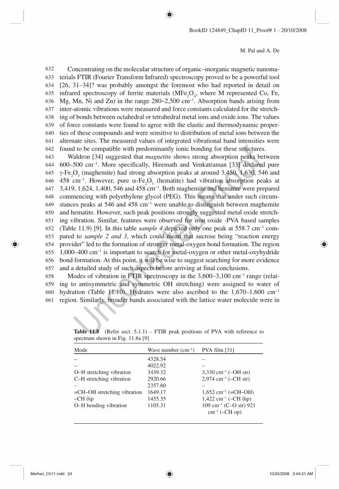
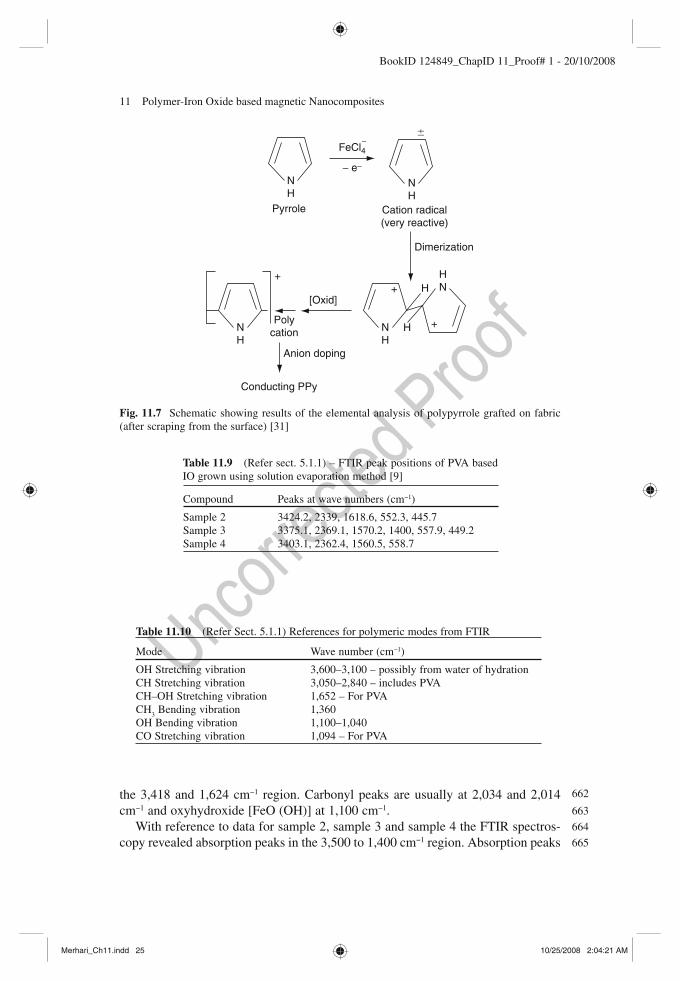
molecular bond structures of PVA were compared with polypyrrole (PPy) (3,400 cm −1 (–NH str), 3,100 cm −1 (C–H str), 1,529 cm −1 (C = C and C–C str), 1,445 cm −1 (C–N str), 1,295 cm −1 (C–H and N–H def), 1,242 cm −1 (C–N str and C–H def) and 1,050 cm −1 (–CH def)) [31] (Fig. 11.7 ).
Fig. 11.6 (1) XRD spectra of 10 nm IO nanoparticles (a) without and (b) with oxidation by (CH
3 )
3 NO. (2) XRD spectra of (a) 3 nm, (b) 5 nm, (c) 10 nm, (d) 16 nm and (e) 25 nm IO particles
without oxidation by (CH 3 )
3 NO [9]
628
629
630
631
Merhari_Ch11.indd 23Merhari_Ch11.indd 23 10/25/2008 2:04:20 AM10/25/2008 2:04:20 AM
24 M. Pal and A. De
BookID 124849_ChapID 11_Proof# 1 - 20/10/2008
Concentrating on the molecular structure of organic–inorganic magnetic nanoma-terials FTIR (Fourier Transform Infrared) spectroscopy proved to be a powerful tool [26, 31– 34] ? was probably amongst the foremost who had reported in detail on infrared spectroscopy of ferrite materials (MFe
2 O
4 , where M represented Co, Fe,
Mg, Mn, Ni and Zn) in the range 280–2,500 cm −1 . Absorption bands arising from inter-atomic vibrations were measured and force constants calculated for the stretch-ing of bonds between octahedral or tetrahedral metal ions and oxide ions. The values of force constants were found to agree with the elastic and thermodynamic proper-ties of these compounds and were sensitive to distribution of metal ions between the alternate sites. The measured values of integrated vibrational band intensities were found to be compatible with predominantly ionic bonding for these structures.
Waldron [34] suggested that magnetite shows strong absorption peaks between 600–500 cm −1 . More specifically, Hiremath and Venkatraman [33] declared pure g -Fe
2 O
3 (maghemite) had strong absorption peaks at around 3,450, 1,630, 546 and
458 cm −1 . However, pure a -Fe 2 O
3 (hematite) had vibration absorption peaks at
3,419, 1,624, 1,400, 546 and 458 cm −1 . Both maghemite and hematite were prepared commencing with polyethylene glycol (PEG). This means that under such circum-stances peaks at 546 and 458 cm −1 were unable to distinguish between maghemite and hematite. However, such peak positions strongly suggested metal oxide stretch-ing vibration. Similar, features were observed for iron oxide -PVA based samples (Table 11.9 ) [9] . In this table sample 4 depicted only one peak at 558.7 cm −1 com-pared to sample 2 and 3 , which could mean that sucrose being “reaction energy provider” led to the formation of stronger metal-oxygen bond formation. The region 1,000–400 cm −1 is important to search for metal-oxygen or other metal-oxyhydride bond formation. At this point, it will be wise to suggest searching for more evidence and a detailed study of such aspects before arriving at final conclusions.
Modes of vibration in FTIR spectroscopy in the 3,600–3,100 cm −1 range (relat-ing to antisymmetric and symmetric OH stretching) were assigned to water of hydration (Table 11.10 ). Hydrates were also ascribed to the 1,670–1,600 cm −1 region. Similarly, broader bands associated with the lattice water molecule were in
Table 11.8 (Refer sect. 5.1.1) – FTIR peak positions of PVA with reference to spectrum shown in Fig. 11.8a [9]
Mode Wave number (cm −1 ) PVA film [31]
– 4328.54 – – 4022.92 – O–H stretching vibration 3439.32 3,330 cm −1 (–OH str) C–H stretching vibration 2920.66 2,974 cm −1 (–CH str) – 2357.60 – =CH–OH stretching vibration 1649.17 1,652 cm −1 (=CH–OH) –CH d ip 1455.35 1,422 cm −1 (–CH d ip) O–H bending vibration 1105.31 109 cm −1 (C–O str) 921
cm −1 (–CH op)
632
633
634
635
636
637
638
639
640
641
642
643
644
645
646
647
648
649
650
651
652
653
654
655
656
657
658
659
660
661
Merhari_Ch11.indd 24Merhari_Ch11.indd 24 10/25/2008 2:04:21 AM10/25/2008 2:04:21 AM
11 Polymer-Iron Oxide based magnetic Nanocomposites 25
BookID 124849_ChapID 11_Proof# 1 - 20/10/2008
NH
NH
NH
HN
NH
�
FeCl4-
Pyrrole Cation radical(very reactive)
Dimerization
H
H
Anion doping
Polycation
Conducting PPy
[Oxid]
+
+
+
- e-
Fig. 11.7 Schematic showing results of the elemental analysis of polypyrrole grafted on fabric (after scraping from the surface) [31]
Table 11.9 (Refer sect. 5.1.1) – FTIR peak positions of PVA based IO grown using solution evaporation method [9]
Compound Peaks at wave numbers (cm −1 )
Sample 2 3424.2, 2339, 1618.6, 552.3, 445.7 Sample 3 3375.1, 2369.1, 1570.2, 1400, 557.9, 449.2 Sample 4 3403.1, 2362.4, 1560.5, 558.7
Table 11.10 (Refer Sect. 5.1.1) References for polymeric modes from FTIR
Mode Wave number (cm −1 )
OH Stretching vibration 3,600–3,100 – possibly from water of hydration CH Stretching vibration 3,050–2,840 – includes PVA CH–OH Stretching vibration 1,652 – For PVA CH
3 Bending vibration 1,360
OH Bending vibration 1,100–1,040 CO Stretching vibration 1,094 – For PVA
the 3,418 and 1,624 cm −1 region. Carbonyl peaks are usually at 2,034 and 2,014 cm −1 and oxyhydroxide [FeO (OH)] at 1,100 cm −1 .
With reference to data for sample 2, sample 3 and sample 4 the FTIR spectros-copy revealed absorption peaks in the 3,500 to 1,400 cm −1 region. Absorption peaks
662
663
664
665
Merhari_Ch11.indd 25Merhari_Ch11.indd 25 10/25/2008 2:04:21 AM10/25/2008 2:04:21 AM
26 M. Pal and A. De
BookID 124849_ChapID 11_Proof# 1 - 20/10/2008
near 3,400–3,300 cm −1 were possibly due to water of hydration, while those about 1,650–1,550 cm −1 could be from =CH–OH and weaker modes of CH bonding con-tributed by PVA. So, it may be possible to say that some molecular contributions from PVA do exist, but the peak positions change from their parent configuration due to resultant effect in the nanocomposite.
Yu and Chow [35] reported on surface-functionalized magnetic nanoparticles by synthesis of poly-methacrylic acid (PMAA) coated maghemite nanoparticles in aqueous solution. Maghemite nanoparticles with an average diameter of about 6–10 nm were fabricated and were coated with PMAA by emulsion polymerization. From FTIR and thermal analysis chemical adsorption of methacrylic acid on the maghemite nanoparticle surface was confirmed and the existence of a symmetrical carboxylate bonding was suggested. It was further claimed that the free carboxyl group of PMAA provided the site for immobilization of foreign molecules.
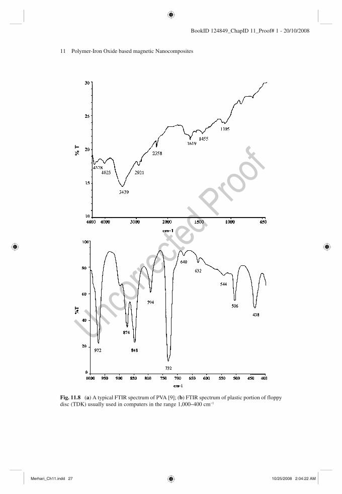
An effort was made to understand some characteristic features of a mem-ory device. For this purpose infrared spectroscopy (FTIR) of a piece of floppy disc (TDK) was done. The point of interest was to compare the vibration absorption spectrum of the organic–inorganic composite with that of the pure inorganic oxide magnetic material. This was the reason why the region from 1,000 to 400 cm −1 was scanned in particular. It can be observed that the pol-ymer-based floppy disk has a very strong and characteristic absorption of infrared radiation. Such absorption behavior of molecules in the polymer of the floppy disk is predominant over absorption characteristics of the metal oxide. As a consequence, the infrared absorption modes of metal oxides are rather camouflaged. However, further work in this aspect may be interesting to the readers. A typical FTIR spectrum of a cut piece of floppy disc (TDK) has been shown (Figs 11.8b and 11.9 ).
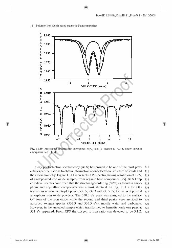
In Sect. 5.1 preparation of amorphous iron oxide powders using microwave heat-ing was described. Structural confirmation of amorphous and crystalline states of such iron oxide powders was done using X-ray photoelectron spectroscopy (XPS) and Mössbauer spectroscopy (MS). The MS spectra of amorphous and crystalline samples at 300 K are displayed in Fig 11.10 [25] . Figure 11.10a shows the MS spectrum for the amorphous sample. The central part of the spectrum exhibits only a broad doublet, which clearly indicates that no long-range magnetic ordering is present. The two quadrupole doublets with a relative ratio of ~2:1 were assigned to unequivalent Fe sites in the amorphous material. The hyperfine parameters of the major doublets were IS = 0.38(1) and quadrupole splitting D = eqQ/2 = 0.56(1), and for the minor one IS = 0.40(1) mm/s and D = 0.96(1) mm/s respectively, with a common line width of 0.30(1) mm/s. Such values are typical for Fe +3 in the high-spin state, and the doublets were attributed to Fe
2 O
3 in the amorphous form. On the
other hand, MS spectrum for the crystalline sample depicted clearly typical hyper-fine magnetic splitting confirming long-range magnetic ordering at low tempera-tures. The interpretation of the spectrum resulted in a magnetic hyperfine field of H
eff = 523(2) kOe, and IS = 0.38(1) mm/s, with an effective quadrupole splitting of
D eff
= 0.21(1) mm/s. The data was in good agreement with g -Fe 2 O
3 : H
eff = 520(1)
kOe and D eff
= 0.22(1) mm/s.
666
667
668
669
670
671
672
673
674
675
676
677
678
679
680
681
682
683
684
685
686
687
688
689
690
691
692
693
694
695
696
697
698
699
700
701
702
703
704
705
706
707
708
709
710
Merhari_Ch11.indd 26Merhari_Ch11.indd 26 10/25/2008 2:04:22 AM10/25/2008 2:04:22 AM
11 Polymer-Iron Oxide based magnetic Nanocomposites 27
BookID 124849_ChapID 11_Proof# 1 - 20/10/2008
Fig. 11.8 ( a ) A typical FTIR spectrum of PVA [9] ; ( b ) FTIR spectrum of plastic portion of floppy disc (TDK) usually used in computers in the range 1,000–400 cm −1
Merhari_Ch11.indd 27Merhari_Ch11.indd 27 10/25/2008 2:04:22 AM10/25/2008 2:04:22 AM

28 M. Pal and A. De
BookID 124849_ChapID 11_Proof# 1 - 20/10/2008
a
b
c
Fig. 11.9 FTIR spectra for Iron Oxide ( a ) Sample 2, ( b ) Sample 3, and ( c ) Sample 4 [9] as described in Table 11.2
Merhari_Ch11.indd 28Merhari_Ch11.indd 28 10/25/2008 2:04:23 AM10/25/2008 2:04:23 AM
11 Polymer-Iron Oxide based magnetic Nanocomposites 29
BookID 124849_ChapID 11_Proof# 1 - 20/10/2008
X-ray photoelectron spectroscopy (XPS) has proved to be one of the most pow-erful experimentations to obtain information about electronic structure of solids and their stoichiometry. Figure 11.11 represents XPS spectra, having resolution of 1 eV, of as-deposited iron oxide samples from organic base compounds [25] . XPS Fe2p core-level spectra confirmed that the short-range-ordering (SRO) as found in amor-phous and crystalline compounds was almost identical. In Fig. 11.11a the O1s transitions represented triplet peaks, 530.5, 532.3 and 533.5 eV, for the as deposited amorphous iron oxide powders. The 530.5 eV peak was assigned to the surface O 2− ions of the iron oxide while the second and third peaks were ascribed to adsorbed oxygen species (532.3 and 533.5 eV), mostly water and carbonate. However, in the annealed sample which transformed to hematite, only one peak at 531 eV appeared. From XPS the oxygen to iron ratio was detected to be 3.1:2.
Fig. 11.10 Mössbauer spectra: ( a ) amorphous Fe 2 O
3 and ( b ) heated to 773 K under vacuum
amorphous Fe 2 O
3 [25]
711
712
713
714
715
716
717
718
719
720
721
722
Merhari_Ch11.indd 29Merhari_Ch11.indd 29 10/25/2008 2:04:24 AM10/25/2008 2:04:24 AM

30 M. Pal and A. De
BookID 124849_ChapID 11_Proof# 1 - 20/10/2008
Figure 11.11b shows a doublet peak. The binding energy at 711 eV was assigned to the Fe2p
3/2 transition and at 725 eV to the Fe2p
1/2 transition.
11.5.1.2 Magnetic Behavior
In a very initial and simple step, demonstrated in an undergraduate laboratory, it was observed that placing a permanent magnet near to the crucible containing the powdered iron oxide attracted the total powdery mass. Further lowering of the magnet towards
a200
160
120
80
40
120
100
80
60
Inte
nsity
(C
PS
) �
10
Inte
nsity
(C
PS
) �
10
b
536
735 730 725 720 715 710 705
534 532 530 528binding energy (eV)
binding energy (eV)
Fig. 11.11 X-ray photoelectron spectroscopy (XPS) spectra of the as-prepared product: ( a ) XPS spectra of the Fe2p core level and ( b ) spectra of the O1s transitions [25]
723724725726727728729730731732733734735736737738739740741742743744745746747748749750751752753754755756757758759760761762763764765766767768769770771772773774775776
Merhari_Ch11.indd 30Merhari_Ch11.indd 30 10/25/2008 2:04:25 AM10/25/2008 2:04:25 AM

11 Polymer-Iron Oxide based magnetic Nanocomposites 31
BookID 124849_ChapID 11_Proof# 1 - 20/10/2008
the powdered iron oxide pulled the whole mass out of the crucible and nothing remained in the crucible. This indicated that despite using PVA as a non-magnetic substance in solution and heating process, no non-magnetic substance exists in the powdered material. However, it was expected that some residual non-magnetic sub-stance remains in the crucible. This strongly suggests that either the polymeric substance decomposes/evaporates to the atmosphere or gets bonded to iron oxide in some form or the other.
Vibrating Sample Magnetometry (VSM) gives a description of the magnetic nature of the magnetic nanocomposite. Typical VSM results of magnetic nano-composite materials are shown in many systems (Figs. 11.12 , 11.16 , 11.19 , 11.20 and 11.23 ). In one of the cases it is interesting to observe the characteristic VSM of amorphous iron oxide prepared from organic compound (Fig. 11.12 ) [28] . The figure indicates a characteristic superparamagnetic behavior of iron oxide particles though saturation magnetization and hysteresis does not occur even at 15 Kgauss.
Yogo et al. [24] reported that in the case of hybrid IAA, oligomer methylhy-drazine was a stronger reducing agent than hydrazine for the formation of spi-nel oxide. Selection of the reducing agent imposes a greater influence on the magnitude of saturation magnetization of iron oxide hybrid compared to varia-tion in solution concentration. The molar ratio of iron, hydrazine derivative and water was maintained at 1:4:10 [24] . The hybrid formed at a higher solution concentration, the hydrolysis of Fe–O bonds and crystallization of magnetic particles precede more rapidly yielding magnetic particles with higher crystal regularity. A comparison of values for saturation magnetization is compiled in Table 11.11 .
Fig. 11.12 Magnetic measurements of amorphous Fe 2 O
3 (magnetization versus applied field) [25]
777
778
779
780
781
782
783
784
785
786
787
788
789
790
791
792
793
794
795
796
797
798
799
800
801
Merhari_Ch11.indd 31Merhari_Ch11.indd 31 10/25/2008 2:04:25 AM10/25/2008 2:04:25 AM
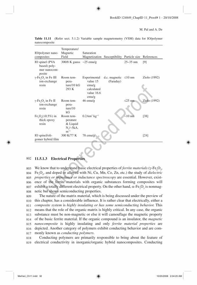
32 M. Pal and A. De
BookID 124849_ChapID 11_Proof# 1 - 20/10/2008
11.5.1.3 Electrical Properties
We know that to understand basic electrical properties of ferrite materials ( g -Fe 2 O
3 ,
Fe 3 O
4 , and doped or alloyed with Ni, Cu, Mn, Co, Zn, etc.) the study of dielectric
properties or impedance or inductance spectroscopy are essential. However, exist-ence of the ferrite materials with organic substances forming composites will exhibit a totally different electrical property. On the other hand, a -Fe
2 O
3 is nonmag-
netic but shows semiconducting properties. The nature of the matrix material, which is being discussed under the preview of
this chapter, has a considerable influence. It is rather clear that electrically, either a composite system is highly insulating or has some semiconducting behavior. This means that the role of the organic matrix is highly critical. In any case, the organic substance must be non-magnetic or else it will camouflage the magnetic property of the basic ferrite material. If the organic compound is an insulator, the magnetic nanocomposite is highly insulating and only ferrite material properties are depicted. Another category of polymers exhibit conducting behavior and are com-monly known as conducting polymers .
Conducting polymers are primarily responsible to bring about the feature of electrical conductivity in inorganic/organic hybrid nanocomposites. Conducting
Table 11.11 (Refer sect. 5.1.2) Variable sample magnetometry (VSM) data for IO/polymer nanocomposite
IO/polymer nano-composites
Temperature/Magnetic Field
Saturation Magnetization Susceptibility Particle size References
IO spinel (PVA based) poly-mer nanocom-posite
300/8 K gauss ~25 emu/g 25–35 nm [9]
g -Fe 2 O
3 in Fe III
ion-exchange resin
Room tem-pera-ture/10 kG 293 K
Experimental value 15 emu/g calculated value 16.6 emu/g
d.c. magnetic (Faraday)
£ 10 nm Ziolo (1992)
g -Fe 2 O
3 in Fe II
ion-exchange resin
Room tem-pera-ture/10 kG
46 emu/g £ 25 nm Ziolo (1992)
Fe 3 O
4 ( £ 0.5%) in
thick epoxy resin
Room tem-perature & Liquid N
2 /~5kA.
m −1
0.2Am 2 kg −1 ~10 nm [38]
IO spinel/oli-gomer hybrid film
300 K/77 K 78 emu/g [24]
802
803
804
805
806
807
808
809
810
811
812
813
814
815
816
817
818
819
Merhari_Ch11.indd 32Merhari_Ch11.indd 32 10/25/2008 2:04:25 AM10/25/2008 2:04:25 AM

11 Polymer-Iron Oxide based magnetic Nanocomposites 33
BookID 124849_ChapID 11_Proof# 1 - 20/10/2008
polymers usually have electrical conductivity which can be tailored to desired val-ues, and are organic electrochromic materials with chemically active surfaces. However, they are chemically sensitive and are mechanically unprocessable. Unique dimensional properties of nanomaterials offer more sites for surface reactivity and a high degree of porosity in sol form, improved mechanical properties, and disperses homogeneously in the matrix medium. Nanocomposites are a combination of conducting polymers and inorganic nanoparticles. These are highly useful and technologically important.
Polypyrrole, an example of non-magnetic conducting polymer , gives high degree nanocomposites. Iron oxide, as a magnetic nanomaterial, forms nanocom-posites with polypyrrole by a process of simultaneous gelation of oxide. A variation of conductivity as a function of concentration of polypyrrole depicts an optimum maximum value rather than monotonic increase in conductivity. In a report it was observed that the electrical conductivity changed by almost 2 orders of magnitude, with a maximum value of 11.3 s cm −1 [28] . The electrical conduction phenomenon may be explained on basis of percolation theory [39] . Percolation theory predicts that for a certain optimum amount of concentration of the conducting polymer a full conducting path is formed for the flow of the current.
11.5.1.4 Optical Behaviour
Figure 11.13 shows diffuse reflection of g -Fe 2 O
3 and a -Fe
2 O
3 , based on the polyol
method, in the visible to near UV region. From 300 nm till about 550 nm both phases had no reflection. Above 550 nm till 800 nm a phase transformation from maghemite to hematite drastically increased the reflection. In accordance with the
Fig. 11.13 Diffuse reflection of Fe 2 O
3 particles after preparation (squares) and after heating to
523 K (circles) [27]
820
821
822
823
824
825
826
827
828
829
830
831
832
833
834
835
836
837
838
839
840
841
842
Merhari_Ch11.indd 33Merhari_Ch11.indd 33 10/25/2008 2:04:26 AM10/25/2008 2:04:26 AM
34 M. Pal and A. De
BookID 124849_ChapID 11_Proof# 1 - 20/10/2008
crystal structure, the color of the powder changed significantly from brownish red to characteristic red after heating to 523 K [27] .
11.5.2 Embedded Magnetic Nanoparticles
11.5.2.1 Ion Exchange Resin
The polymer matrix may either be commercial based or in-lab synthesized ion-exchange resin. Ziolo et al. [36] selected a commercial ion-exchange resin, which was com-posed of sulphonated polysterene cross linked with divinyl benzene to form a three-dimensional, porous polymer network. The dry resin exhibited the property of cation exchange . The cross linked resin was in the form of spherical beads of diameter 30–150 m m. The resin was exchanged with Fe (II) or Fe (III) from an aqueous solu-tion of the respective chloride. The process of washing removed excess physisorbed Fe ions. From elemental analysis of the resins, Fe: S atom ratios of 1:2 or 1:3 con-firmed complete ion exchange. Considering Fe (II) resin, exposure to a solution of NaOH caused a rapid change in color to green followed by a gradual change to deep red-black on exposure to air. Heating to 333 K followed by the drop wise addition of a dilute aqueous H
2 O
2 solution accelerated the conversion to oxide formation. For Fe
(III) resin, an aqueous suspension of the resin was heated and maintained at 333 K during drop wise addition of N
2 H
4 with stirring. Aqueous NaOH was added in subse-
quent steps to make it highly alkaline (pH ~ 13–14). For both the resins the stirring was continued for many hours, then they were washed with water several times to bring them to neutral pH and finally dried. From elemental analysis of Fe (II) and Fe (III) resins, the Fe content was found to be 9.8 and 7.8% respectively.
Structural Properties
Transmission electron microscope (TEM) analysis of Fe (II) in an ion-exchange resin (Fig. 11.14 ) [36] depicted a relatively uniform, high-density distribution of oxide in the polymer matrix (Fig. 11.15 ). The TEM micrograph showed the crystal-line phase present in the material of either spherical or cubic shape, which were only due to iron oxide ( g -Fe
2 O
3 ) particles. Higher iron oxide contents or loadings
increased the particle size rather than their number. However, with multiple load-ings of Fe initially the number (density) of particles increased in the polymer matrix rather than their size. By increasing the cyclic process many folds, the oxide particle size could be varied from about 5 to 25 nm.
Magnetic Properties
Using vibrating sample magnetometry (VSM), a Fe (II) ion-exchange resin com-posite having 15.28% Fe, meaning 21.8% by weight loading of g -Fe
2 O
3 , was shown
843
844
845
846
847
848
849
850
851
852
853
854
855
856
857
858
859
860
861
862
863
864
865
866
867
868
869
870
871
872
873
874
875
876
877
Merhari_Ch11.indd 34Merhari_Ch11.indd 34 10/25/2008 2:04:27 AM10/25/2008 2:04:27 AM

11 Polymer-Iron Oxide based magnetic Nanocomposites 35
BookID 124849_ChapID 11_Proof# 1 - 20/10/2008
AU5
to possess a magnetic saturation moment of 15 emu/g (experimental value) at a magnetic field of 10 kG (Table 11.11 ) (Ziolo 1992 ). The superparamagnetic behav-ior of nanocomposites was also confirmed from measurements of dc magnetic susceptibility, determined by the Faraday method as a function of temperature and magnetic field. Field dependent magnetization at low temperatures (10 K), field cooled and zero field cooled, brought out the hysteresis in the iron oxide compos-ites and confirmed that the particles were magnetically single-phased (Fig. 11.16 ). Coercivity of about 1 kOe indicated randomly oriented equiaxial particles with cubic magnetocrystalline anisotropy [40] .
O3S·
O3S· O3S·Na+
O3S·Na+
O3S·Na+
O3S·Na+
Fe2+2 NaOH
Fe(OH)2
FeCl2 · 4H2O for recycling
g -Fe2O3H2O2
D
Fig. 11.14 Schematic of the g -Fe 2 O
3 precipitation process using Fe (II) in an ion-exchange resin [36]
Fig. 11.15 Bright-field transmission electron micrograph of a microtomed section of composite containing 21.8% g -Fe
2 O
3 by weight in an 8% cross-linked polystyrene resin. The iron oxide
particles range in size from 5 to 10 nm [36]
878
879
880
881
882
883
884
885
886
Merhari_Ch11.indd 35Merhari_Ch11.indd 35 10/25/2008 2:04:27 AM10/25/2008 2:04:27 AM

36 M. Pal and A. De
BookID 124849_ChapID 11_Proof# 1 - 20/10/2008
Optical Nature
Optical absorption of the Fe (II) ion-exchange resin composite having the form of spherical beads of diameter about 45 m m was observed in the visible region (4,500–7,500 Å) [36] . Using optical microprobe for the absorption measurements, the lens effects with field stops to limit the effective aperture near the optical axis under parallel illumination in the region 5–7 m m of the beads could be minimized, and the refractive index (calibrated depth-measurement scale) calculated (average refractive index = 1.6 ± 0.1 for the 21.8% by weight loaded beads) after correction for reflection loss.
1.6a
b
1.2
0.8
0.4
0
−0.4
−0.8
−1.2
−1.6−10 −8 −6 −4 −2 0
Applied field (kOe)2 4 6 8 10
Mag
net
izat
ion
(em
u/g
)
Field cooledH = 200 Oe
1.6
1.2
0.8
0.4
0
−0.4
−0.8
−1.2
−1.6−10 −8 −6 −4 −2 0
Applied field (kOe)2 4 6 8 10
Mag
net
izat
ion
(em
u/g
)
Zero field cooled
Fig. 11.16 ( a ) Field-cooled magnetization curve at 10 K and 200 Oe for a Fe (II) resin containing 8.5 nm g -Fe
2 O
3 at 2% by weight; ( b ) Zero-field-cooled curve at 10 K for the same sample [36]
887
888
889
890
891
892
893
894
Merhari_Ch11.indd 36Merhari_Ch11.indd 36 10/25/2008 2:04:27 AM10/25/2008 2:04:27 AM
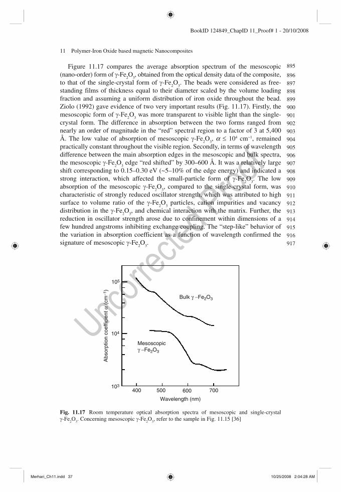
11 Polymer-Iron Oxide based magnetic Nanocomposites 37
BookID 124849_ChapID 11_Proof# 1 - 20/10/2008
Figure 11.17 compares the average absorption spectrum of the mesoscopic (nano-order) form of g -Fe
2 O
3 , obtained from the optical density data of the composite,
to that of the single-crystal form of g -Fe 2 O
3 . The beads were considered as free-
standing films of thickness equal to their diameter scaled by the volume loading fraction and assuming a uniform distribution of iron oxide throughout the bead. Ziolo (1992) gave evidence of two very important results (Fig. 11.17 ). Firstly, the mesoscopic form of g -Fe
2 O
3 was more transparent to visible light than the single-
crystal form. The difference in absorption between the two forms ranged from nearly an order of magnitude in the “red” spectral region to a factor of 3 at 5,400 Å. The low value of absorption of mesoscopic g -Fe
2 O
3 , a £ 10 4 cm −1 , remained
practically constant throughout the visible region. Secondly, in terms of wavelength difference between the main absorption edges in the mesoscopic and bulk spectra, the mesoscopic g -Fe
2 O
3 edge “red shifted” by 300–600 Å. It was a relatively large
shift corresponding to 0.15–0.30 eV (~5–10% of the edge energy) and indicated a strong interaction, which affected the small-particle form of g -Fe
2 O
3 . The low
absorption of the mesoscopic g -Fe 2 O
3 , compared to the single-crystal form, was
characteristic of strongly reduced oscillator strength, which was attributed to high surface to volume ratio of the g -Fe
2 O
3 particles, cation impurities and vacancy
distribution in the g -Fe 2 O
3 , and chemical interaction with the matrix. Further, the
reduction in oscillator strength arose due to confinement within dimensions of a few hundred angstroms inhibiting exchange coupling. The “step-like” behavior of the variation in absorption coefficient as a function of wavelength confirmed the signature of mesoscopic g -Fe
2 O
3 .
105
104
103
Abs
orpt
ion
coef
ficie
nt α
(cm
−1)
400 500 600 700
Wavelength (nm)
Bulk γ −Fe2O3
Mesoscopicγ −Fe2O3
Fig. 11.17 Room temperature optical absorption spectra of mesoscopic and single-crystal g -Fe
2 O
3 . Concerning mesoscopic g -Fe
2 O
3 , refer to the sample in Fig. 11.15 [36]
895
896
897
898
899
900
901
902
903
904
905
906
907
908
909
910
911
912
913
914
915
916
917
Merhari_Ch11.indd 37Merhari_Ch11.indd 37 10/25/2008 2:04:28 AM10/25/2008 2:04:28 AM
38 M. Pal and A. De
BookID 124849_ChapID 11_Proof# 1 - 20/10/2008
11.5.2.2 Epoxy Resin
Thorpe et al. [38] worked with aqueous suspension of 10 nm magnetite particles (sizes about 1–2 m m across) in bis-phenol-based epoxy matrix, using sonication to attain uniform dispersion in the medium, and then hardening the resin by means of a polyamine-based hardener. It was observed using optical microscopy (126×) that for samples containing magnetite particles above 0.5% in the epoxy resin matrix, clumps of larger size introduced irregular spheroid shapes. The sizes were as large as several tens of microns across.
Structural Properties
Magnetite (approximately 5 wt%) phase was confirmed from XRD in magnetite epoxy resins (MER) [38] . Heating of such MER indicated absence of water in the material and an estimation of magnetostatic forces which confirmed spherical shapes of magnetites.
Optical microscopy of MER showed relatively large elongated clumps of magnetite particles in MER. Scanning electron microscopy (SEM) of MER revealed clumping formation of about 50 m m for samples containing 2% of magnetite, but nothing of that sort was observed at concentrations of 0.39% magnetite samples. Such a phenomenon was also confirmed from TEM results. It was concluded that in the case of the mag-netite dispersion the magnetostatic forces produced the spherical agglomerates in the aqueous phase. After and during the hardening stage, the water was displaced by epoxy and the magnetite agglomerates maintained their spherical shape.
Micro-focus X-ray fluorescence ( m -XRF) offers yet another way to detect mag-netite agglomeration in MER or polymeric or glassy matrices, at much lower con-centrations. The X-ray beam (white radiation) with a spot dimension of about 1–2 m m, a solid-state detector (to measure fluorescent radiation) and a background fil-tration are characteristic of m -XRF. A typical m -XRF analysis of MER is repre-sented in Fig.11.18. Figure 11.18a indicates the difference in concentration, which is evident from the number of peaks in each sample. Figures 11.18b , c are subse-quent scans (in a different position) for each sample on an expanded scale. Figure 11.18c is the best of the three spectra, as some of the background interference was filtered out. In Fig.11.18c most of the peaks in the filtered spectrum fall into two categories, i.e., narrowest peaks with a base of about 7 m m, and the rest with con-siderable wider bases. The narrowest peaks probably correspond to single aggre-gates, whereas the wider peaks could be caused by a combination of aggregates at various depths. This was primarily due to the size of the beam and the dispersion of the X-rays in the sample. It was speculated that small angle X-ray detectors could examine aggregated or single particles of the order of 10 nm or better. With a high-intensity photon source, m -XRF spectroscopy has shown its potential as a powerful tool for the characterization of solid nanodispersions at very low concen-trations. On the other hand TEM could detect nanodispersions in thin samples (up to 200 nm) at concentrations of >0.1%. At low concentrations TEM measurements
918
919
920
921
922
923
924
925
926
927
928
929
930
931
932
933
934
935
936
937
938
939
940
941
942
943
944
945
946
947
948
949
950
951
952
953
954
955
956
957
958
Merhari_Ch11.indd 38Merhari_Ch11.indd 38 10/25/2008 2:04:28 AM10/25/2008 2:04:28 AM
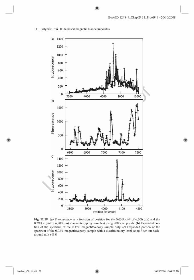
11 Polymer-Iron Oxide based magnetic Nanocomposites 39
BookID 124849_ChapID 11_Proof# 1 - 20/10/2008
Fig. 11.18 ( a ) Fluorescence as a function of position for the 0.03% ( left of 6,200 m m) and the 0.39% ( right of 6,200 m m) magnetite (epoxy samples) using 200 scan points. ( b ) Expanded por-tion of the spectrum of the 0.39% magnetite/epoxy sample only. ( c ) Expanded portion of the spectrum of the 0.03% magnetite/epoxy sample with a discriminatory level set to filter out back-ground noise [38]
Merhari_Ch11.indd 39Merhari_Ch11.indd 39 10/25/2008 2:04:28 AM10/25/2008 2:04:28 AM
40 M. Pal and A. De
BookID 124849_ChapID 11_Proof# 1 - 20/10/2008
were difficult because of the large inter-agglomerate distances. The synchro m -XRF spectroscopy extended the range of sample size to several orders greater than the detection level of TEM. Moreover, it was also capable to detect small concentra-tions of particles in thick opaque samples. The absolute detection limit provided by synchro m -XRF spectroscopy was very low (~10 −16 g).
Magnetic Properties
It was interesting to learn that hysteresis curves for MER containing Fe 3 O
4 concentra-
tions greater than 1.5 wt% were irregular and not characteristic of bulk or mesoscopic (10 nm) magnetite. However, for MER containing about 0.39% magnetite in epoxy, typical hysteresis curves were obtained. It was suggested that at higher concentrations of magnetite, ~3.4% magnetite epoxy sample, clumping occurred resulting in irregu-lar hysteresis curves. So, in a way low and high concentration of magnetite in MER referred to two-dimensional and three-dimensional agglomerates [38] .
The coercive force (40–60 Am −1 ) of small non-interacting particles has been known to increase with particle size up to a certain optimum value (~5–20 nm). The saturation magnetization of the MER samples having low concentrations increased linearly with the concentration of magnetite in the epoxy. The individual particles were less than a single domain in size (superparamagnetic), and therefore it appeared that there was little interaction of particles below a concentration of 0.5–1 wt%.
Optical Properties
The IAA oligomer hybrid films were cast on a fused silica substrate from an ethanol solution consisting of hybrid and 10 wt% poly (vinylbutyral) (PVB) [24] . The hybrid was prepared through hydrolysis of IAA oligomer with 4 equivalent of CH
3 NHNH
2
and 1/6 equivalent of water at 50°C for 3 h, because the films were required to have not only magnetism but also transparency (Fig. 11.19 ). The hybrid films contained 10 wt% IO. The change of magnetization with applied field for the IAA oligomer hybrid film at 300 K has been shown (Fig. 11.20 ). The magnetic induction clearly indicates that the transparent film is magnetic, though the film has no coercive force.
A comparison of the optical transmittance and absorption coefficient as func-tions of wavelength and photon energy in the region 1,000–2,600 nm for iron oxide spinel/oligomer hybrid film on a fused silica and absorption of PVB is highlighted in Fig. 11.21 . It is observed that the absorption coefficient is small compared with that of bulk Fe
3 O
4 . A single-crystal g -Fe
2 O
3 thin film having a thickness of about
0.3 m m, epitaxially grown on an MgO substrate, showed a refractive index of about 3.0 corresponding to that of hematite (Ziolo 1992).
Xue et al. [41] prepared thin films of a -Fe 2 O
3 from Fe (III) 2-ethylhexanoate
which is a metal organic compound, employing spin – coating process for film growth on silicon substrates. From FTIR of a -Fe
2 O
3 films, peaks at 1323.3, 1423.5,
1589.4 and 1716.7 cm −1 were attributed to C–H modes. The chain ( n (C–H)) in the
959
960
961
962
963
964
965
966
967
968
969
970
971
972
973
974
975
976
977
978
979
980
981
982
983
984
985
986
987
988
989
990
991
992
993
994
995
996
997
Merhari_Ch11.indd 40Merhari_Ch11.indd 40 10/25/2008 2:04:30 AM10/25/2008 2:04:30 AM
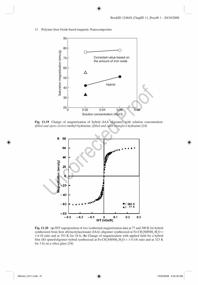
11 Polymer-Iron Oxide based magnetic Nanocomposites 41
BookID 124849_ChapID 11_Proof# 1 - 20/10/2008
90
80
70
60
50
40
30
20
Sat
urat
ion
mag
netiz
atio
n (e
mu/
g)
0 0.02 0.04
Solution concentration (mol/l)
0.06 0.08
Hybrid
Corrected value based onthe amount of Iron oxide
Fig. 11.19 Change of magnetization of hybrid (IAA oligomer) with solution concentration: ( filled and open circles ) methyl hydrazine; ( filled and open triangles ) hydrazine [24]
Fig. 11.20 ( a ) H/T superposition of two isothermal magnetization data at 77 and 300 K for hybrid synthesized from Iron allylacetylacetonate (IAA) oligomer synthesized at Fe:CH
3 NHNH
2 :H
2 O =
1:4:10 ratio and at 353 K for 24 h; ( b ) Change of magnetization with applied field for a hybrid film (IO spinel/oligomer hybrid synthesized at Fe:CH
3 NHNH
2 :H
2 O = 1:4:1/6 ratio and at 323 K
for 3 h) on a silica glass [24]
Merhari_Ch11.indd 41Merhari_Ch11.indd 41 10/25/2008 2:04:30 AM10/25/2008 2:04:30 AM

42 M. Pal and A. De
BookID 124849_ChapID 11_Proof# 1 - 20/10/2008
Fig. 11.21 (I) Optical transmittance and absorption coefficient as functions of wavelength and h n for IO spinel/oligomer hybrid film on a fused silica substrate: ( filled circle ) absorption of poly (vinyl-butyral) PVB; (II) Optical transmittances as a function of wavelength for IO spinel/oligomer hybrid film and PVB film: (a) absorption edge of bulk g -Fe
2 O
3 , (b) absorption edge of bulk Fe
3 O
4 , (a) mag-
netic hybrid film on a fused silica substrate, and (b) PVB film on a fused silica substrate [24]
2b
1.5
1
0.5
0
−0.5
−1
−1.5
−2
Mag
netiz
atio
n (e
mu
/g)
−5 −4 −3 −2 −1 0Applied field (kOe)
1 2 3 4 5
Fig.11.20. continiued
Merhari_Ch11.indd 42Merhari_Ch11.indd 42 10/25/2008 2:04:31 AM10/25/2008 2:04:31 AM

11 Polymer-Iron Oxide based magnetic Nanocomposites 43
BookID 124849_ChapID 11_Proof# 1 - 20/10/2008
metal-organic molecule was identified at 2,961 cm −1 . The amorphous a -Fe 2 O
3 films
had a broad absorption band at 532 cm −1 , while crystalline a -Fe 2 O
3 films showed a
1,085 cm −1 band corresponding to FeO. The basic idea was to study the phase transition from amorphous to crystalline in the films, which occurred at an annealing temperature of about 733 K. The corresponding XRD data are being tabulated (Table 11.7 ).
11.5.2.3 Magnetic Fluids (MF)
Typically MF are realized as ferrofluids . It was a two-fold investigation. Firstly, mag-netic particles of two ferrofluids differing in magneto-crystalline energy of the dis-persed particles were considered. Secondly, textured fluids were introduced in paraffin wax under different texturing magnetic fields [42] . In one such type of a sample, magnetite particles showed anisotropy energy much greater than thermal energy at room temperature. In another type of a sample, Mn–Zn ferrite particles had thermal energy greater than the anisotropy energy. Chain formation in ferrofluid films was observed using CCD camera under different magnetic field [20] (Fig. 11.22 ).
11.5.2.4 Rubber Ferrite Composite (RFC)
Nickel zinc ferrites Ni 1–x
Zn x Fe
2 O
4 (NZF) and Mn
1–x Zn
x Fe
2 O
4 (MZF) [21, 22, 37]
were prepared using the ceramic technique [12] . Natural rubber (NR) and butyl rubber (BR) were selected as the polymer matrix for mixing the magnetic filler
Fig. 11.21 (continued)
998
999
1000
1001
1002
1003
1004
1005
1006
1007
1008
1009
1010
1011
1012
1013
1014
1015
1016
Merhari_Ch11.indd 43Merhari_Ch11.indd 43 10/25/2008 2:04:32 AM10/25/2008 2:04:32 AM
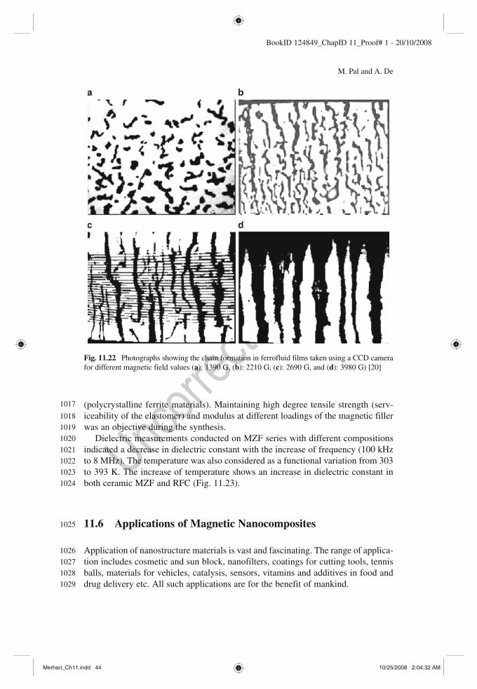
44 M. Pal and A. De
BookID 124849_ChapID 11_Proof# 1 - 20/10/2008
(polycrystalline ferrite materials). Maintaining high degree tensile strength (serv-iceability of the elastomer) and modulus at different loadings of the magnetic filler was an objective during the synthesis.
Dielectric measurements conducted on MZF series with different compositions indicated a decrease in dielectric constant with the increase of frequency (100 kHz to 8 MHz). The temperature was also considered as a functional variation from 303 to 393 K. The increase of temperature shows an increase in dielectric constant in both ceramic MZF and RFC (Fig. 11.23 ).
11.6 Applications of Magnetic Nanocomposites
Application of nanostructure materials is vast and fascinating. The range of applica-tion includes cosmetic and sun block, nanofilters, coatings for cutting tools, tennis balls, materials for vehicles, catalysis, sensors, vitamins and additives in food and drug delivery etc. All such applications are for the benefit of mankind.
Fig. 11.22 Photographs showing the chain formation in ferrofluid films taken using a CCD camera for different magnetic field values ( a ): 1390 G, ( b ): 2210 G, ( c ): 2690 G, and ( d ): 3980 G) [20]
1017
1018
1019
1020
1021
1022
1023
1024
1025
1026
1027
1028
1029
Merhari_Ch11.indd 44Merhari_Ch11.indd 44 10/25/2008 2:04:32 AM10/25/2008 2:04:32 AM
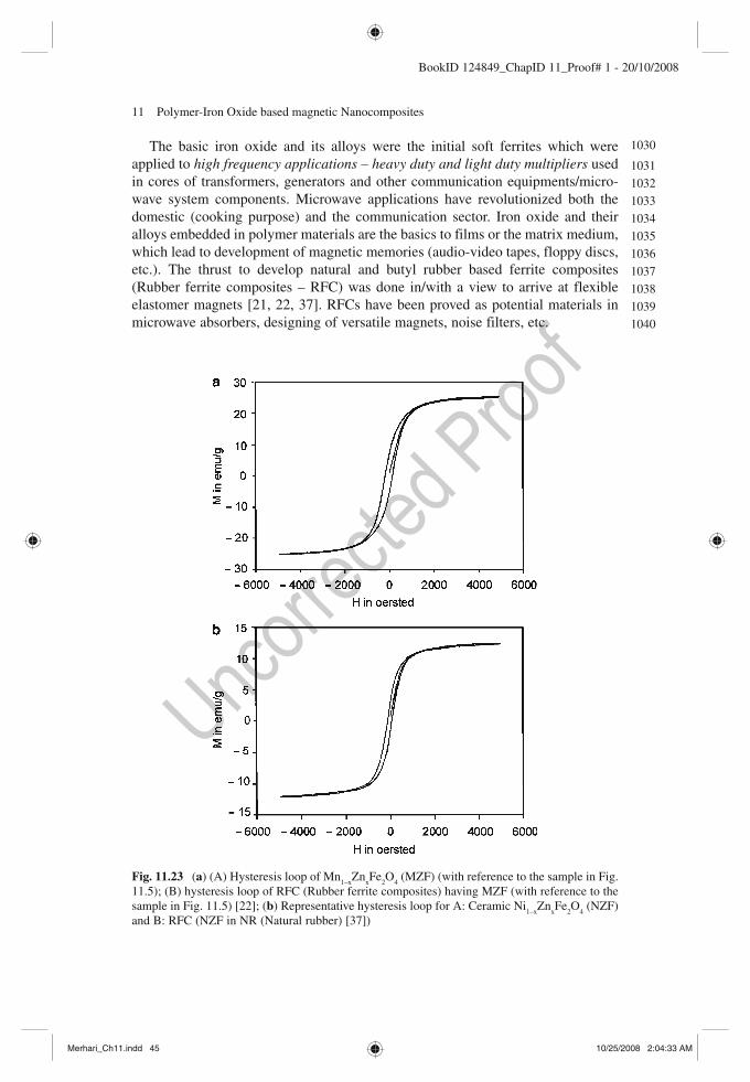
11 Polymer-Iron Oxide based magnetic Nanocomposites 45
BookID 124849_ChapID 11_Proof# 1 - 20/10/2008
The basic iron oxide and its alloys were the initial soft ferrites which were applied to high frequency applications – heavy duty and light duty multipliers used in cores of transformers, generators and other communication equipments/micro-wave system components. Microwave applications have revolutionized both the domestic (cooking purpose) and the communication sector. Iron oxide and their alloys embedded in polymer materials are the basics to films or the matrix medium, which lead to development of magnetic memories (audio-video tapes, floppy discs, etc.). The thrust to develop natural and butyl rubber based ferrite composites (Rubber ferrite composites – RFC) was done in/with a view to arrive at flexible elastomer magnets [21, 22, 37] . RFCs have been proved as potential materials in microwave absorbers, designing of versatile magnets, noise filters, etc.
Fig. 11.23 ( a ) (A) Hysteresis loop of Mn 1–x
Zn x Fe
2 O
4 (MZF) (with reference to the sample in Fig.
11.5 ); (B) hysteresis loop of RFC (Rubber ferrite composites) having MZF (with reference to the sample in Fig. 11.5 ) [22] ; ( b ) Representative hysteresis loop for A: Ceramic Ni
1–x Zn
x Fe
2 O
4 (NZF)
and B: RFC (NZF in NR (Natural rubber) [37] )
1030
1031
1032
1033
1034
1035
1036
1037
1038
1039
1040
Merhari_Ch11.indd 45Merhari_Ch11.indd 45 10/25/2008 2:04:33 AM10/25/2008 2:04:33 AM
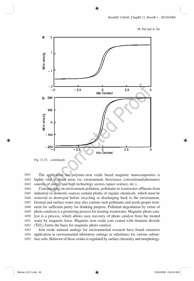
46 M. Pal and A. De
BookID 124849_ChapID 11_Proof# 1 - 20/10/2008
The application for polymer–iron oxide based magnetic nanocomposites is highly vital in thrust areas viz. environment, bioscience, conventional/alternative sources of energy and high technology sectors (space science, etc.).
Concentrating on environment pollution, pollutants in wastewater effluents from industrial or domestic sources contain plenty of organic chemicals, which must be removed or destroyed before recycling or discharging back to the environment. Ground and surface water may also contain such pollutants and needs proper treat-ment for sufficient purity for drinking purpose. Pollutant degradation by virtue of photo catalysis is a promising process for treating wastewater. Magnetic photo cata-lyst is a process, which allows easy recovery of photo catalyst from the treated water by magnetic force. Magnetic iron oxide core coated with titanium dioxide (TiO
2 ) forms the basis for magnetic photo catalyst.
Iron oxide mineral analogs for environmental research have found extensive application in environmental laboratory settings as substitutes for various subsur-face soils. Behavior of these oxides is regulated by surface chemistry and morphology.
Fig. 11.23. (continued)
1041
1042
1043
1044
1045
1046
1047
1048
1049
1050
1051
1052
1053
1054
1055
Merhari_Ch11.indd 46Merhari_Ch11.indd 46 10/25/2008 2:04:34 AM10/25/2008 2:04:34 AM

11 Polymer-Iron Oxide based magnetic Nanocomposites 47
BookID 124849_ChapID 11_Proof# 1 - 20/10/2008
There are reports where iron oxide mineral analogs are characterized to represent natural iron oxide minerals in water distribution systems and in subsurface environ-ments. Iron oxide mineral analogs were procured as crushed corrosion products from a water pipe and glass beads coated with iron oxide by a forced acid hydrolysis technique [43] . Corrosion products were found to be a mixture of five highly crystalline forms of iron oxide including goethite ( a -FeOOH), ferrihydrite (Fe
5 O
7 (OH)
4 H
2 O), iron hydroxide (Fe (OH)
3 ), ferroxyhite ( d -FeOOH), and
lepidocrocite ( g -FeOOH). Though we have been mainly discussing on the soft magnetic materials, hard
magnetic nanoparticles have shown immense potential for increasing magnetic storage devices.
Magnetic nanomaterials have also been used in filters to remove selected impu-rities from various types of fluids. The separation of organic contaminants such as polyaromatic hydrocarbons from water and the removal of sulfur compounds from hydrocarbon fuels are also being investigated with magnetic fluids.
The most promising aspect of pharmaceuticals and medicine as it relates to nanotechnology is currently drug delivery . In the area of biomedicine, nano-scale dimensional features are those for cell (10–100 m m), virus (20–450 nm), protein (5–50 nm). This is quite indicative that magnetic nanoparticles be associated with biomedicines. Magnetic nanoparticles can be coated with biological molecules to make them interactive with or bind to a biological entity, thereby providing a spe-cific tag or address for controllable mechanism. The nanoparticles are magnetic, which means they obey Coulomb’s law and can be manipulated by an external magnetic field gradient. This action at a distance, combined with the intrinsic pen-etrability of magnetic fields into human tissue, opens up many applications involv-ing the transport and immobilization of magnetic nanoparticles, or of magnetically tagged biological entities. Thus a package can be delivered (say an anticancer drug) and targeted to the affected region of the body i.e., a tumor. There are reports on some special physical properties of magnetic nanoparticles for their potential appli-cation in biomedicine [44, 45] .
In the area for cancer treatment, a relatively non-specific feature of chemother-apy is one of its major disadvantages. The therapeutic drugs are administered intra-venously leading to general systematic distribution, resulting in deleterious side effects as the drug attacks normal, healthy cells in addition to the target tumor cells. However, if such treatments could be localized or brought exactly to the affected site, then the continued use of very potent and effective agents could be made pos-sible. This was probably the main impetus to recognize the purpose to use magnetic carriers to target specific sites (generally cancerous tumors) within the body. In magnetically targeted therapy, a cytotoxic drug is attached to a biocompatible mag-netic nanoparticle carrier [46] . The PMAA coated maghemite nanoparticles are recognized as potential magnetically targeted drug carriers by adsorbing an anti-cancer drug (carboplatin) by virtue of the ion-dipole interaction between CO
2 − of
PMAA and carboplatin [35] . Towards mid-twentieth century, impetus for research in space and astronomy
grew rapidly. There arose a necessity for controlling liquids in space (zero gravity
1056
1057
1058
1059
1060
1061
1062
1063
1064
1065
1066
1067
1068
1069
1070
1071
1072
1073
1074
1075
1076
1077
1078
1079
1080
1081
1082
1083
1084
1085
1086
1087
1088
1089
1090
1091
1092
1093
1094
1095
1096
1097
1098
1099
1100
Merhari_Ch11.indd 47Merhari_Ch11.indd 47 10/25/2008 2:04:35 AM10/25/2008 2:04:35 AM

48 M. Pal and A. De
BookID 124849_ChapID 11_Proof# 1 - 20/10/2008
problems). This led to the development of ferrofluids , which are colloidal suspensions of magnetic nanoparticles (e.g., Fe
3 O
4 of size about 10 nm
) in a
liquid. The response of ferrofluids to external magnetic fields offered smooth control of fluid movement required for mechanical or other physical action. Magnetic elements and their alloy oxides (Fe, Co, Zn, and Mn) were basic to ferrofluids. Mostly ferrofluids refer to magnetite (Fe
3 O
4 ) nanoparticles in some
liquid medium. It is essential that the nanoparticles remain separate from one another in the liquid medium forming a homogenous system. If there is any tendency for agglomeration of magnetic nanoparticles in the medium, it will cause anisotropic behavior of the ferrofluid, which in turn will spoil its purpose. Magnetic and van der Waals interactions must be overcome to prevent the par-ticles from agglomeration into larger particles. Superparamagnetic property is highly dependent on particle size. Thermal motion of magnetic particles that are smaller than 10 nm in size is sufficient to prevent agglomeration due to magnetic interactions. Surfactants (oleic acid or tetramethylammonium hydrox-ide) are added to oil-based or aqueous-based ferrofluids to prevent the nanopar-ticles from approaching one another very closely. The surfactants are basically long-chain hydrocarbon with a polar head that attaches itself to the surface of the magnetite particle. The long chains comprising the tails, act as a repellent cushion and prevent the close approach of another particle. Spikes are observed when the ferrofluids are subjected to strong magnetic fields. Such spikes arise from a tendency of the particles to line up along the magnetic field lines to lower their energy. The presence of surface tension in fluids restricts the extent to which the particles can align themselves within the field. The main application areas of ferrofluids are:
1. Mechanical movements in regions not easily approachable viz. rotating shaft seals in X-ray generators and in vacuum chambers.
2. High speed computer disk drives. 3. Improving performance of loudspeakers (damping of unwanted resonance and
dissipating heat in the coils). 4. Migratory sense of animals. 5. Biomedical applications (targeted medicines and magnetic resonance imaging
MRI).
Magnetic materials (FeBO 3 and FeF
3 ) transparent in the visible region (absorption
coefficient £ 40 cm −1 ) at room temperature have caught up tremendous interest (Ziolo 1992) and [47] . This area included colored magnets, bead like magnets and low-density magnetic microphores.
11.7 Prospective Areas and Challenges
There are some excellent contributions in the area of organic–inorganic magnetic nanocomposites [2, 47– 49] , and Ziolo 1992.
1101
1102
1103
1104
1105
1106
1107
1108
1109
1110
1111
1112
1113
1114
1115
1116
1117
1118
1119
1120
1121
1122
1123
1124
1125
1126
1127
1128
1129
1130
1131
1132
1133
1134
1135
1136
1137
1138
1139
1140
Merhari_Ch11.indd 48Merhari_Ch11.indd 48 10/25/2008 2:04:35 AM10/25/2008 2:04:35 AM

11 Polymer-Iron Oxide based magnetic Nanocomposites 49
BookID 124849_ChapID 11_Proof# 1 - 20/10/2008
Since early 1990s magnetic properties of molecular based materials caught the interest of physicists, chemists and mathematicians. A host of interdisciplinary areas opened up with bioscience providing the living conditions and man-made problems.
Structural based problems and their relation to different magnetic properties kindled the initial interest. To state a few are simple dinuclear or oligonuclear spe-cies, one-dimensional materials (Spin Hamiltonians). A few examples could be cited: molecular ferrimagnet (based on copper (II)-manganese (II) derivatives, organic building blocks (dithiocarbamate iron (III) complex), polycarbenes, Prussian blue compounds, etc.
Certain systems comprising of a finite number of interacting magnetic centers led to an interdisciplinary approach for zero-dimensional magnets, thanks to quan-tum effects in magnets. The main hurdles were to obtain assemblies of identical particles, which had to scale exponentially with the size of the particles. It was understood that magnetic interaction between the particles be minimized. To cite some examples viz. iron loaded ferritin, Mn
12 (a cluster of twelve Mn ions) acetate,
cluster of eight iron (III) ions, etc. Yet another area of immense interest has been magnetic semiconductors and
diluted magnetic semiconductors (ZnO: Co or Mn) [49– 51] . We identify some challenges, which can be the goal setters for research in
organic-inorganic magnetic nanocomposites:
(a) Better synthesis method to ensure nanomaterials of desired size, distribution, shape, morphology and chemical composition resulting in the most required properties.
(b) More sophisticated tools to characterize and study the nanomaterials. (c) Specific care to prevent coarsening of magnetic particles. (d) Clear understanding of the relationship between microstructure and related
properties. (e) Especially, for magnetic nanocomposites one cannot go on reducing the size in
the superparamagnetic region for higher storage capacity. This brings about instability in the system.
11.8 Concluding Remarks
In this chapter some aspects of iron oxide/organic magnetic nanocomposite materials have been addressed. The primary concern dealt with different ways to develop iron oxide and its alloys, which originated from organic based compounds. By pursuing so many different phases of iron oxide, amorphous and crystalline structures were studied. It is quite apparent that many more areas have not been included.
Molecular composition and bonding configurations existing in organic–inorganic nanocomposites were studied employing mainly infrared spectroscopy. It is this area which is still not yet fully understood.
1141
1142
1143
1144
1145
1146
1147
1148
1149
1150
1151
1152
1153
1154
1155
1156
1157
1158
1159
1160
1161
1162
1163
1164
1165
1166
1167
1168
1169
1170
1171
1172
1173
1174
1175
1176
1177
1178
1179
1180
Merhari_Ch11.indd 49Merhari_Ch11.indd 49 10/25/2008 2:04:35 AM10/25/2008 2:04:35 AM

50 M. Pal and A. De
BookID 124849_ChapID 11_Proof# 1 - 20/10/2008
It is very clear that there are host of routes to arrive at organic–inorganic mag-netic nanocomposites. Till date plenty of research has been carried out. However, there are many questions still unanswered and not properly understood. The target and motivation to achieve such a goal, as briefly compiled in the application part, is also set. Everyday problems keep modifying our priority areas and it is not sure which pathway nanotechnology will follow but it can be concluded with certainty that world will be different from what we know now.
Acknowledgements I (AD) am highly grateful to the Department of Science and Technology (DST) – Funds for Improvement in Science and Technology (FIST) for providing essential sup-port to build the basic infrastructure for research and development, and the graduate advance labo-ratory for academic development in our department. I am also thankful to the University Grants Commission (UGC) to provide me scope and funds by granting me a project UGC-MNR (2002–2004) in an area which was fairly new to me. I thank all my colleagues in our department and members of my family who provided me the impetus and encouragement to complete this chapter despite of many shortcomings. I am indebted to Dr M. Pal who on my request joined me as coau-thor, in the final stage, to make this chapter a success. Finally, I must thank Prof. L. Merhari for giving me the opportunity to form such a chapter, providing me constant guidance and attending to any of my queries.
References
1 . Cullity B.D. (1972) Introduction to Magnetic Materials . Addison-Wesley , Reading, MA , pp 383 – 441 .
2. Blundell S.J. (2001) Magnetism in Condensed Matter . Oxford University Press , New York , pp 180 – 182 .
3 . Morrish A.H. (1965) The Physical Principles of Magnetism . Wiley , New York , p 360 . 4. Bean C. and Livingston J. (1959) Journal of Alied Physics Sulementary 30 , p 1205 . 5 . Klug H.P. and Alexander L.E. (1954) X-Ray Diffraction Procedures – For polycrystalline and
Amorphous Materials . Wiley , New York , p 687 . 6. Pathak A. and Pramanik P. (2000) Nanoparticles of Oxides Through Chemical Route
(Nanomaterials) (ed.) Chakraborty D., 47. 7. Pierre A.C. (1998) Introduction to Sol-Gel Processing . USA , Kluwer , p 24 – 47 ; 110,161 . 8 . Roy R. (1987) Ceramics by the solution sol-gel route . Science 238 , pp 1664 – 1669 . 9. De A. (2004) Low molecular weight polymer based nanostructured ferrite materials. In:
Nano 2004 India: International Conference on Nano-Materials: Synthesis, Characterization and Alication, Kolkata, India. Tata McGraw-Hill, New Delhi, India, 496–498.
10 . Pramanik P. and Pathak A. (1994) A new chemical route for the preparation of fine ferrite powders . Bulletin of Materials Science 17 , pp 967 – 975 .
11 . Pramanik P. (1999) A novel chemical route for the preparation of nanosized oxides, phos-phates, vanadates, molybdates and tungstates . Bulletin of Materials Science 22 , pp 335 – 339 .
12. Valenzuela R. (1994) Magnetic Ceramics . Cambridge University Press , Cambridge, New York .
13 . Pal M. , Brahma P. , Chakravorty D. , Bhattacharya D. and Maiti H.S. (1997) Preparation of nanocrystalline barium hexaferrite in a glass medium . Nanostructured Materials 8 , pp 731 – 738 .
14 . Pal M. , Das D. , Chintalapudi S.N. and Chakravorty D. (2000) Preparation of nanocomposites containing iron and nickel-zinc ferrite . Journal of Materials Research 15 , pp 683 – 688 .
[AU6]
1181
1182
1183
1184
1185
1186
1187
11881189119011911192119311941195119611971198
1199
12001201120212031204120512061207120812091210121112121213121412151216121712181219122012211222122312241225
Merhari_Ch11.indd 50Merhari_Ch11.indd 50 10/25/2008 2:04:36 AM10/25/2008 2:04:36 AM
11 Polymer-Iron Oxide based magnetic Nanocomposites 51
BookID 124849_ChapID 11_Proof# 1 - 20/10/2008
15 . Stavroyiannis S. , Panagiotopoulos I. , Niarchous D. (1998) CoPt/Ag nanocomposites for high density recording media . Alied Physics Letters A 73 , p 3453
16 . Inoue N. , Kawamura Y. and Morimoto K. (1997) Molecular beam epitaxy: Handbook of Nanophase Materials (ed.) A N Goldstein . Marcel Dekker , New York , pp 83 – 140 .
17 . Ping D.H. and Hono K. (1998) Partitioning of Ga and Co atoms in a Fe 3 B/Nd 2 Fe 14 B nano-composite magnet . Journal of Alied Physics 83 , p 7769 .
18 . McCormick P.G. , Miao W.F. , Smith P.A.I. , Ding J. and Street R. (1998) Mechanically alloyed nanocomposite magnets . Journal of Alied Physics 83 , p 6256 .
19 . Craik D.J. (1975) Magnetic Oxides part 2 . Wiley , New York , pp 697 – 708 . 20 . Abraham V.S. , Swapna Nair S. , Rajesh S. , Sajeev U.S. and Anantharaman M.R. (2004)
Magnetic field induced assembling of nanoparticles in ferrofluidic liquid thin film based on Ni
x Fe
1–x Fe
2 O
4 . Bulletin of Materials Science 27 , pp 155 – 161 .
21 . Anantharaman M.R. , Sindhu S. , Jagatheesan S. , Malini K.A. and Kurian P. (1999) Dielectric properties of rubber ferrite composites containing mixed ferrites . Journal of Physics D: Alied Physics 32 , pp 1801 – 1810 .
22 . Mohammed E.M. , Malini K.A. , Kurian P. , and Anantharaman M.R. (2002) Modification of dielectric and mechanical properties of rubber ferrite composites containing manganese zinc ferrite . Materials Research Bulletin 37 , pp 753 – 768
23. Tadakoro H. (1979) Structure of Polymers . Wiley-Interscience , San Francisco , pp 213 – 214 ; 358; 381 .
24 . Yogo T. , Nakamura T. , Sakamoto W. , and Hirano S. (2000) Synthesis of transparent magnetic particle/organic hybrid films using iron-organics . Journal of Material Research 15 (10) , pp 2114 – 2120 .
25 . Palchik O. , Felner I. , Kataby G. and Gedanken A. (2000) Amorphous iron oxide prepared by microwave heating . Journal of Materials Research 15 (10) , pp 2176 – 2181 .
26 . Chauhan P. , Annapoorni S. and Trikha S.K. (1998) Preparation, characterization and optical properties of a -Fe
2 O
3 films by sol-spinning process . Bulletin of Material Science 21 ,
pp 381 – 385 . 27. Jungk H-O. , and Feldmann C. (2000) Nanoagglomerated, submicron a -Fe
2 O
3 particles:
Preparation and alication . Journal of Material Research 15 , pp 2244 – 2248 . 28 . Suri K. , Annapoorni S. , and Tandon R.P. (2001) Phase change induced by polypyrrole in
iron-oxide polypyrrole nanocomposite . Bulletin of Materials Science 24 , pp 563 – 567 . 29 . Venkatraman A. , Hiremath V.A. , Date S.K. and Kulkarni S.D. (2001) A new combustion
route to g -Fe 2 O
3 synthesis . Bulletin of Materials Science 24 , pp 617 – 621 .
30 . Bunn C.W. (1948) Crystal structure of polyvinyl alcohol . Nature 161 , pp 929 – 930 . 31 . Dhawan S.K. and Trivadi D.C. (1993) Thin conducting polypyrrole film on insulating surface
and its alications . Bulletin of Material Science 16 , pp 371 – 380 . 32 . Deb P. , Biswas T. , Sen D. , Basumallick A. and Mazumder S. (2002) Characteristics of Fe
2 O
3
nanoparticles prepared by heat treatment of a non-aqueous powder precipitate . Journal of Nanoparticle Research 4 , pp 91 – 97 .
33 . Hiremath V.A. and Venkatraman A. (2003) Dielectric, electrical and infrared studies of g -Fe
2 O
3 prepared by combustion method . Bulletin of Material Science 26 , p 391 – 396 .
34 . Waldron R.D. (1955) Infrared spectra of ferrites . Physical Review 99 , pp 1727 – 1735 . 35. Yu S. and Chow G.M. (2004) Carboxyl group (–CO 2 H) functionalized ferromagnetic iron
oxide nanoparticles for potential bio-alications . Journal of Materials Chemistry 14 , p p2781 36 . Ziolo R.F. , Giannelis E.P. , Weinstein B.A. , O’Horo M.P. , Ganguly B.N. , Mehrotra V. ,
Russell M.W. , and Huffman D.R. (1992) Matrix-mediated synthesis of nanocrystalline g -Fe
2 O
3 : A new optically transparent magnetic material . Science 257 , pp 219 – 223 .
37 . Anantharaman M.R. , Malini K.A. , Sindhu S. , Mohammed E.M. , Date S.K. , Kulkarni S.D. , Joy P.A. and Kurian P. (2001) Tailoring magnetic and dielectric properties of rubber ferrite composites containing mixed ferrites . Bulletin of Material Science 24 , pp 623 – 631 .
38. Thorpe A.N. , Senftle F.E. , Holt M. , Grant J. , Lowe W. , Anderson H. , Williams E ., Monkres and Barkatt A . (2000) Magnetization, micro-X-ray fluorescence, and transmission electron
12261227122812291230123112321233123412351236123712381239124012411242124312441245124612471248124912501251125212531254125512561257125812591260126112621263126412651266126712681269127012711272127312741275127612771278
Merhari_Ch11.indd 51Merhari_Ch11.indd 51 10/25/2008 2:04:36 AM10/25/2008 2:04:36 AM
52 M. Pal and A. De
BookID 124849_ChapID 11_Proof# 1 - 20/10/2008
Author Queries
Chapter No.: Merhari_Ch11
Queries Details Required Author’s Response
AU1 The figures given are not in sequence and some some figures are not cited, so figures citation has been added. Please check whether the insertion of the figure citations 11.1, 11.7, 11.9, 11.14, 11.19, 11.22, 11.23 in the text are appropriate.
AU2 Please check whether you intend to have box here.
AU3 The reference “Venkataraman 2001” is cited but not given in the list. Please provide.
AU4 Please check the insertion of the table citations 11.3, 11.5, 11.7, 11.10 in the text are appropriate.
AU5 The reference “Ziolo 1992” is cited but not given in the list. Please provide.
AU6 Please provide the publisher name and location for the refer-ence [6]
microscopy studies of low concentrations of nanoscale Fe 3 O
4 particles in epoxy resin . Journal
of Materials Research 15 , pp 2488 – 2493 . 39. Stauffer D. (1985) Introduction to Percolation Theory . Taylor & Francis , London . 40. Kneller E. (1969) Magnetism and Metallurgy, Vol. 1, chapter 1 (eds.) Berkowitz A.E. and
Kneller E. Academic, New York. 41 . Xue S. , Ousi-Benomar W. and Lessard R.A. (1994) a -Fe
2 O
3 thin films prepared by metalor-
ganic deposition from Fe (III) 2-ethylhexanoate . Thin Solid Films 250 , pp 194 – 201 . 42 . Gadhvi M. , Upadhyay R.V. , Parekh K. and Mehta R.V. (2004) Magnetically textured fer-
rofluid in a non-magnetic matrix: magnetic properties . Bulletin of Materials Science 27 , pp 163 – 168 .
43. Borch T. , Biederman J.A. , Mogk D.W. , Butterfield P.W. , Camper A.K. and Jordan R.N. (2003) Characterization of Two Iron Oxide Models for Environmental Research: Microscopic and Spectroscopic Studies – A Research Report . Center for Biofilm Engineering, Montana State University , Bozeman, MT .
44 . Pankhurst Q.A. , Connolly J. , Jones S.K. and Dobson J. (2003) Alications of magnetic nano-particles in biomedicine . Journal of Physics D: Alied Physics 36 , pp R167 – R181 .
45. Shinkai M. (2002) Functional magnetic particles for medical alication . Journal of Bioscience and Bioengineering 94 , pp 606 – 613 .
46 . Kaámár S., Koneracká M., Kopáanský P., Timko M., Sequiera A., De, and Trevan M. (2001) Entrapment of anticancer drug 5 Fluorouracil in magnetoliposome vesicles. Zborník konf. SSB, 127.
47 . Ziolo R.F. (1994) Magnets-value of the first step . R&D Innovator 3 (11) , p 127 . 48. Kahn O. (1993) Molecular Magnetism . Wiley , Weinheim . 49 . Samarth N. (2006) Semiconductor physics: Magnetic manipulations . Nature 442 ,
pp 359 – 360 . 50. Rubi D. , Calleja A. , Arbiol J. , Capdevila X.G. , Segarra M. , Aragonès L.I. and Fontcuberta J.
(2005) Structural and magnetic properties of ZnO: TM (TM: Co, Mn) nanopowders . Journal of Magnetism and Magnetic Materials 316 (2) , pp e211 – e214 .
51. Pal M. and Pal M. (2005) Nanocrystalline Mn-doped ZnO by chemical route . Japanese Journal of Alied Physics 44 , pp 7901 – 7903 .
127912801281128212831284128512861287128812891290129112921293129412951296129712981299130013011302130313041305130613071308
Merhari_Ch11.indd 52Merhari_Ch11.indd 52 10/25/2008 2:04:36 AM10/25/2008 2:04:36 AM
Top Related