


Languages
Pages
Legal

Prepared GoBe Consultants Ltd, September 2021
Checked Sarah Randall, September 2021
Accepted Francesca De Vita, Orsted, September 2021
Approved Julian Carolan, Orsted, September 2021
Doc. no. B2.2.F
Version A
[
Hornsea Project Four: Reports PINS Document Reference: B2.2 APFP Regulation: 5(2)(g)
B2.2: Report to Inform Appropriate Assessment Part 9: Appendix F: Maximum Design Scenario
Page 1/29
Doc. No: B2.2.F
Ver. No. A
Impact Receptor
Group
Maximum Design Scenario (MDS) Assessed Justification
Construction
Temporary habitat
disturbance in the
Hornsea Four array
area and offshore
Export Cable Corridor
(ECC) from
construction activities.
Benthic and
Intertidal
Ecology
Temporary habitat disturbance of 75,895,509 m2
Array Area:
Foundation seabed preparation = 779,106 m2
• 110 GBS (Wind Turbine Generator (WTG) type) foundations for WTGs = 411,321 m2;
• 70 suction caisson jacket (WTG type) foundations for WTGs = 198,870 m2. Six small
Offshore Substations (OSS) on suction caisson jacket (small OSS) foundations and
three large OSS on GBS (large OSS) foundations = 156,594 m2; and
• One accommodation platform on a suction caisson jacket (small OSS) foundation
= 12,321 m2.
Jack up and anchoring operations = 1,063,200 m2
• WTG installation jack up vessel (JUV) footprint (six legs, 170 m2 per foot, four jack-
up operations per turbine) = 734,400 m2;
• WTG installation vessel anchor footprints (100 m2 per anchor, eight anchors per
vessel, two anchored vessels per turbine) = 288,000 m2; and
• OSS and accommodation platform installation JUV footprint (six legs, 170 m2 per
foot, four jack-up operations per structure) = 40,800 m2.
Cable seabed preparation and installation in the array area = 37,950,000 m2
• Boulder and sandwave clearance in array area (690 km length, 40 m width) =
27,600,000 m2;
• Burial of array cables (600 km length, 15 m width) = 9,000,000 m2; and
• Burial of inter-connector cables (90 km length, 15 m width) = 1,350,000 m2.
Note the 15 m cable width is located within the boulder and sandwave clearance
40 m width.
Offshore ECC:
• Foundation seabed preparation for three suction caisson jacket (small OSS)
foundations = 36,963 m2; and
• OSS installation JUV footprint (six legs, 170 m2 per foot, four jack-up operations
per structure) = 12,240 m2.
Export cable seabed preparation and installation = 36,054,000 m2
• -Boulder and sandwave clearance in offshore ECC (654 km length, 40 m width) =
26,160,000 m2;
• -Burial of export cables (654 km length, 15 m width) = 9,810,000 m2; and
• Cable jointing (four joints per cable, six cables, 3,500 m2 per joint) = 84,000 m2.
The temporary disturbance relates to
seabed preparation for foundations and
cables, jack up and anchoring operations,
and cable installation. It should be noted
that the seabed preparation area for
foundations is less than the footprint of the
foundation scour protection and the
footprint of infrastructure is assessed as a
permanent impact in the operations and
maintenance phase.
It should be noted that the MDS presents a
precautionary approach to temporary
habitat disturbance because it counts both
the total footprint of seabed clearance as
well as cable burial across both the array
and offshore ECC. This approach
effectively counts the footprint of seabed
habitat to be impacted by construction in
the same area twice. However, this
precautionary approach has been taken
because there is some potential for
recovery of habitats between the activities
due to project timescales.
Page 2/29
Doc. No: B2.2.F
Ver. No. A
Impact Receptor
Group
Maximum Design Scenario (MDS) Assessed Justification
• Note the 15 m cable width is located within the boulder and sandwave clearance
40 m width.
Temporary increase in
SSC and sediment
deposition in the
Hornsea Four array
area and offshore ECC.
Benthic and
Intertidal
Ecology
Total volume 12,192,331 m3.
WTG Foundations:
• 110 turbines on GBS (WTG type) foundations requiring seabed preparation,
resulting in the suspension of 685,794 m3 of sediment.
• 70 Suction Caisson Jacket (WTG type) foundations requiring seabed preparation,
resulting in the suspension of 359,427 m3 of sediment.
OSS Foundations (array):
• Six OSS on suction caisson jacket (small OSS) foundations and three OSS on GBS
(large OSS) foundations requiring seabed preparation, resulting in the suspension
of 737,130 m3 of sediment.
Offshore Accommodation Platform Foundations:
• One suction caisson jacket (small OSS) foundation requiring seabed preparation,
resulting in the suspension of 57,245 m3 of sediment.
High Voltage Alternating Current (HVAC) Booster Station Foundations:
• Three suction caisson jacket (small OSS) foundations requiring seabed
preparation, resulting in the suspension of 171,735 m3 of sediment.
Sandwave Clearance:
• Sandwave clearance for 600 km of array cables resulting in the suspension of
769,000 m3 of sediment;
• Sandwave clearance for 90 km of interconnector cables resulting in the
suspension of 115,000 m3 of sediment; and
• Sandwave clearance for 654 km of export cables resulting in the suspension of
834,000 m3 of sediment.
Cable Trenching:
• Installation of 600 km of array cables by Controlled Flow Excavation (CFE)
resulting in the suspension of 3,600,000 m3 of sediment;
• Installation of 90 km of interconnector cables resulting in the suspension of
540,000 m3 of sediment;
• Installation of six export cables by CFE resulting in the suspension of 3,903,000 m3
of sediment (excluding the part of the export cable within the array); and
• Up to 420,000 m3 of sediment from up to four cable joints per export cable in the
The MDS for foundation installation results
from the largest volume suspended from
seabed preparation (GBS and suction
caisson jacket foundations).
For cable installation, the MDS results from
the greatest volume from sandwave
clearance and installation using energetic
means (CFE). This also assumes the largest
number of cables and the greatest burial
depth.
Page 3/29
Doc. No: B2.2.F
Ver. No. A
Impact Receptor
Group
Maximum Design Scenario (MDS) Assessed Justification
ECC.
Temporary increase in
SSC and sediment
deposition in the
intertidal area.
Benthic and
Intertidal
Ecology
Eight offshore cofferdam HDD exit pits require excavation of 20,000 m3 (8 x 2,500
m3) which will be side-cast onto the adjacent seabed. Backfilling of exit pits will
recover a similar amount to be from the surrounding seabed, as required. HDD exit
pits will come out below MLWS, so will not directly impact the intertidal.
HDD Bentonite drilling fluid loss per cable 265 m3.
The MDS for temporary habitat
disturbance in the intertidal area from the
HDD works is included. It is important to
note that HDD exit pits will be located
below MLWS.
Direct and indirect
seabed disturbances
leading to the release
of sediment
contaminants.
Benthic and
Intertidal
Ecology
The MDS for seabed disturbance is presented above (Temporary increase in SSC and
sediment deposition in the Hornsea Four array area and offshore ECC).
The MDS for foundation installation results
from the largest volume suspended from
seabed preparation (GBS and suction
caisson jacket foundations).
For cable installation, the MDS results from
the greatest volume from sandwave
clearance and installation using energetic
means (CFE). This also assumes the largest
number of cables and the greatest burial
depth.
Permanent Threshold
Shift (PTS) and
Temporary Threshold
Shift (TTS) from piling
noise
Marine
Mammals
Spatial MDS:
• 180 Wind Turbine Generators (WTGs) on monopile foundations;
• Six small and three large Offshore Substations (OSS) on monopile foundations;
• One accommodation platform on a monopile foundation;
• Three High Voltage Alternating Current (HVAC) Booster Stations (small OSS) on
monopile foundations;
• Maximum design: 5,000 kJ hammer energy, 4.4 hours piling duration including a
30 min soft start and 22.5 min ramp up;
• Most likely: 4,000 kJ hammer energy, 2.1 hours piling duration including a 30
min soft start and 22.5 min ramp up;
• Total WTG piling days: 216 assuming 1.2 days per monopile over a 12 month
piling period;
• Total non-WTG piling days: 16 assuming 1.2 days per monopile over a 12
month piling period; and
The piling scenario with the largest PTS
impact ranges represent the maximum
design scenario. This differs between
species depending on the frequency
characteristics emitted during installation
of each pile type and the hearing of the
species (e.g. for high frequency cetaceans
such as harbour porpoise, pin piles have a
larger PTS impact range whereas for low
frequency cetaceans, monopiles have a
larger PTS impact range).
The maximum number of piled foundations
would represent the temporal maximum
Behavioural
disturbance from piling
noise
Marine
Mammals
Page 4/29
Doc. No: B2.2.F
Ver. No. A
Impact Receptor
Group
Maximum Design Scenario (MDS) Assessed Justification
• Simultaneous piling: only two piles will be piled simultaneously within the
Hornsea Four array area.
Temporal MDS:
• 180 WTGs on piled jacket (WTG-type) foundations, three piles per jacket (540
total);
• Six small OSS on piled jacket (small OSS) foundations and three large OSS on
piled jacket (large OSS) foundations (144 total piles);
• One accommodation platform on a piled jacket (small OSS) foundation (16
total piles);
• Three HVAC Booster Stations on piled jacket (small OSS) foundations (48 total
piles);
• Maximum design: 3,000 kJ hammer energy, 4.4 hours piling duration including a
30 min soft start and 22.5 min ramp up;
• Most likely: 1,750 kJ hammer energy, 2.1 hours piling duration including a 30
min soft start and 22.5 min ramp up;
• Total WTG piling days: 270 assuming 1.5 days per jacket foundation over a 12
month piling period;
• Total non-WTG piling days: 39 assuming 3 days per jacket foundation over a 12
month piling period; and
• Simultaneous piling: only two piles will be piled simultaneously within the Hornsea
Four array area.
design scenario for disturbance. The
maximum predicted impact range for
underwater noise for piled foundations
would represent the spatial maximum
design scenario for disturbance.
Vessel collision risk Marine
Mammals
Wind Turbine Foundation Installation:
• Up to 2,880 return trips over a 12-month period.
Wind Turbine Installation:
• Up to 900 return trips over a 24-month period.
OSS Installation (all OSSs and the accommodation platform):
• Up to 270 return trips over a two-month period.
OSS Foundation Installation (all OSSs and the accommodation platform):
• Up to 180 return trips over a two-month period.
Inter-Array and Interconnector Cable Installation:
• Up to 1,488 return trips over a 24-month period.
The maximum numbers of vessels and
associated vessel movements represents
the maximum potential for collision risk
and disturbance.
Disturbance from
vessels
Marine
Mammals
Page 5/29
Doc. No: B2.2.F
Ver. No. A
Impact Receptor
Group
Maximum Design Scenario (MDS) Assessed Justification
Offshore Export Cable Installation:
• Up to 408 return trips over a 24-month period.
Total:
• Up to eight vessels in any given 5 km2 at any one time.
Non-piling noise (e.g.
cable laying, dredging)
Marine
Mammals
• Surface lay, mechanical trenching, dredging, jetting, ploughing, controlled flow
excavation, vertical injection, rock cutting.
• Total length of array cables: 600 km;
• Total length of interconnector cables: 90 km;
• Where possible, the export cables will be buried below the seabed through to
landfall.;
• Total length of export cables: 654 km (6 cables x 109 km cable length); and
• Total duration of cable installation: 36 months.
Maximum potential for underwater noise
impacts.
PTS from Unexploded
Ordnance (UXO)
clearance
Marine
Mammals
UXO Clearance:
• Estimated 2,263 targets;
• 86 UXOs may require clearance;
• up to 5 UXO could be detonated per day.
Estimated maximum design based on data
from other projects in the Hornsea Zone. A
detailed UXO survey would be completed
prior to construction. The type, size (net
explosive quantities (NEQ)) and number of
possible detonations and duration of UXO
clearance operations is therefore not
known at this stage.
Disturbance from UXO
clearance
Marine
Mammals
Reduction in prey
availability
Marine
Mammals
See MDS for Fish and Shellfish Ecology assessment (Volume A2, Chapter 3: Fish and Shellfish Ecology).
Reduction in foraging
ability
Marine
Mammals
Total volume 12,192,331 m3
WTG Foundations:
• 110 turbines on Gravity Base Structure (GBS) (WTG type) foundations requiring
seabed preparation, resulting in the suspension of 685,794 m3 of sediment; and
• 70 Suction Caisson Jacket (WTG type) foundations requiring seabed
preparation, resulting in the suspension of 359,427 m3 of sediment.
OSS Foundations (array):
The maximum impacts from remedial
cable burial and cable repairs of array,
interconnector and export cables result
from the use of CFE. This assumes the
largest number of cables, repair events, the
greatest burial depth and greatest
length/area of maintenance. This results in
the maximum sediment volume
disturbance.
Page 6/29
Doc. No: B2.2.F
Ver. No. A
Impact Receptor
Group
Maximum Design Scenario (MDS) Assessed Justification
• Six OSS on suction caisson jacket (small OSS) foundations and three OSS on GBS
(large OSS) foundations requiring seabed preparation, resulting in the
suspension of 737,130 m3 of sediment.
Offshore Accommodation Platform Foundations:
• One suction caisson jacket (small OSS) foundation requiring seabed
preparation, resulting in the suspension of 57,245 m3 of sediment.
High Voltage Alternating Current (HVAC) Booster Station Foundations:
• Three suction caisson jacket (small OSS) foundations requiring seabed
preparation, resulting in the suspension of 171,735 m3 of sediment.
Sandwave Clearance:
• Sandwave clearance for 600 km of array cables resulting in the suspension of
769,000 m3 of sediment;
• Sandwave clearance for 90 km of interconnector cables resulting in the
suspension of 115,000 m3 of sediment; and
• Sandwave clearance for 654 km of export cables resulting in the suspension of
834,000 m3 of sediment.
Cable Trenching:
• Installation of 600 km of array cables by Controlled Flow Excavation (CFE)
resulting in the suspension of 3,600,000 m3 of sediment;
• Installation of 90 km of interconnector cables resulting in the suspension of
540,000 m3 of sediment;
• Installation of six export cables by CFE resulting in the suspension of 3,903,000
m3 of sediment (excluding the part of the export cable within the array); and
• Up to 420,000 m3 of sediment from up to four cable joints per export cable in
the ECC.
Disturbance and
displacement from
increased vessel
activity and
Offshore and
Intertidal
Ornithology
Construction Vessels / Helicopters within Array Area:
• Up to eight construction vessels in a given 5 km2 area with approximately three
or four 5 km2 areas at any one time.
• Single phase of offshore construction over approximately 3 years.
The maximum estimated number of
development areas within the array area
with vessels operating concurrently would
Page 7/29
Doc. No: B2.2.F
Ver. No. A
Impact Receptor
Group
Maximum Design Scenario (MDS) Assessed Justification
helicopters within the
array area
WTG Installation:
• -Up to two installation vessels (Jack Up Vessels (JUV) or anchored) (90 return
trips);
• Up to 12 support vessels (270 return trips);
• Up to 24 transport vessels (540 return trips); and
• Up to 135 helicopter return trips.
WTG Foundation Installation:
• 6 installation vessels (2 anchored or 4DP2 or 6 x Tugs) (90 return trips if anchored
or DP2. 540 return trips if Tugs);
• 19 support vessels (900 return trips);
• 40 transport/feeder vessels (including tugs) (720 return trips);
• 12 dredging vessels (720 return trips); and
• 180 helicopter return trips.
OSS and Accommodation Platform Installation:
• 2 installation vessels (36 return trips);
• 12 support vessels (162 return trips);
• 4 transport/feeder vessels (72 return trips); and
• 63 helicopter return trips.
OSS and Accommodation Platform Foundation Installation:
• 2 installation vessels (24 return trips);
• 12 support vessels (108 return trips);
• 4 transport/feeder vessels (48 return trips); and
• 42 helicopter return trips.
Array and Interconnector Cable Installation:
• 3 main cable laying vessels (204 return trips);
• 3 main cable burial vessels (204 return trips);
• 12 support vessels (1,080 return trips); and
cause the greatest disturbance to birds on
site.
Page 8/29
Doc. No: B2.2.F
Ver. No. A
Impact Receptor
Group
Maximum Design Scenario (MDS) Assessed Justification
• 396 helicopter return trips.
Indirect impacts during
the construction phase
within the array area
through effects on
habitats and prey
species
Offshore and
Intertidal
Ornithology
See MDS for Fish and Shellfish Ecology assessment (Volume A2, Chapter 3: Fish and Shellfish Ecology) and for the Benthic and
Intertidal Ecology assessment (Volume A2, Chapter 2: Benthic and Intertidal Ecology).
Disturbance and
displacement from
vessel activity within
the ECC area
Offshore and
Intertidal
Ornithology
Construction Vessels within ECC:
• 3 cable laying vessels (96 return trips)
• 3 cable jointing vessels (72 return trips)
• 3 cable burial vessels (96 return tips)
• 15 support vessels (144 return trips)
• 800 helicopter return trips
• Single phase of offshore construction over approximately 3 years.
The assumption is that vessels would be in
situ from start to finish, so any disturbance
events would be throughout entire period.
Disturbance and
displacement from
presence and
operation of
construction
machinery/vehicles
within the cable
landfall area
Offshore and
Intertidal
Ornithology
Horizontal Directional Drilling (HDD) Installation:
• Eight offshore HDD exits pits;
• Minimum 6 m entry pit and 5m exit pit depth;
• Small 4x4 vehicles related to emergency response on the beach; and
• Small 4x4 on beach to monitor the drill head using handheld equipment.
Cable Laying:
• Maximum duration of cable laying via HDD is 24 months within a 32 month period.
The assumption is that the process would
be undertaken by HDD methods, so no
open trenching, cable laying and burial of
the export cable would be required.
Therefore, MDS activities to be assess are
limited, though they are to take place over
a maximum of 24 months within a 32
month period (allowing for up to six months
of weather-related downtime).
Direct impacts on
designated sites:
Temporary
construction areas
could occupy areas
leading to loss and/or
degradation of
designated sites
Ecology and
Nature
Conservation
Onshore Export Cable Corridor:
• Construction duration: 30 months;
• Primary logistics compounds: Number: 1, Size: 140x140 m, Duration: 36
months;
• Secondary Logistics compounds: Number: 7, Size: 90x90 m, Duration: 36
months;
• ECC: Length: 39 km (approximate), Width: 80 m, Area: 3,120,000 m2;
• Haul Road: Number: 1, Width: 6 m (with 7 m passing places), Length: 39 km,
Maximum Depth: 1 m, Average Depth: 0.4 m;
These parameters represent maximum
ground disturbance conditions both in
terms of potential size of area affected and
in terms of duration of expected
disturbance.
Page 9/29
Doc. No: B2.2.F
Ver. No. A
Impact Receptor
Group
Maximum Design Scenario (MDS) Assessed Justification
• Temporary access roads: Number: 36, Width: 6 m (with 7 m passing places),
Maximum Depth: 1 m, Average Depth: 0.4 m;
• Joint Bays: Number: 240, Depth 2.5 m, Area: 225 m2 per Joint Bay, Joint Bay
compounds: 240 40x40 m compounds;
• Link Boxes: Number: 240, Depth: 2 m, Area: 9 m2 per Link Box; and
• HDDs: Number: 112, HDD compounds (entry and exit):224 70x70 m
compounds, HDD compounds hardstanding: 46 50x50 m (at approximately
20% of all HDD locations).
400 kV ECC:
• Number of cable circuits: 4;
• Cable trench depth: 1.5 m;
• Approximate Length: 1 km; and
• Width: 60 m.
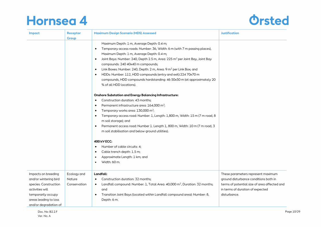
Impacts on bat
species: Construction
activities will
temporarily occupy
areas leading to loss
and/or degradation of
habitat and loss of
habitat connectivity
used by bats for
roosting, commuting
and/or foraging
Ecology and
Nature
Conservation
Landfall:
• Construction duration: 32 months;
• Landfall compound: Number: 1, Total Area: 40,000 m2, Duration: 32 months;
and
• Transition Joint Bays (located within Landfall compound area): Number: 8,
Depth: 6 m.
Onshore Export Cable Corridor:
• Construction duration: 30 months;
• Primary logistics compounds: Number: 1, Size: 140x140 m, Duration: 36
months;
• Secondary Logistics compounds: Number: 7, Size: 90x90 m, Duration: 36
months;
• ECC: Length: 39 km (approximate), Width: 80 m, Area: 3,120,000 m2;
• Number of cable circuits (HVAC system): 6
• Cable trench: Depth: 1.5 m, Width at base: 1.5 m, Width at surface: 5 m;
• Haul Road: Number: 1, Width: 6 m (with 7 m passing places), Length: 39 km,
These parameters represent the maximum
number of crossings, construction duration
and building design parameters that could
potentially disrupt bat
commuting/foraging habitat and/or bat
roosts.
For further detail, see Volume A4, Annex
4.2: Onshore Crossing Schedule.
Page 10/29
Doc. No: B2.2.F
Ver. No. A
Impact Receptor
Group
Maximum Design Scenario (MDS) Assessed Justification
Maximum Depth: 1 m, Average Depth: 0.4 m;
• Temporary access roads: Number: 36, Width: 6 m (with 7 m passing places),
Maximum Depth: 1 m, Average Depth: 0.4 m;
• Joint Bays: Number: 240, Depth 2.5 m, Area: 225 m2 per Joint Bay, Joint Bay
compounds: 240 40x40 m compounds;
• Link Boxes: Number: 240, Depth: 2 m, Area: 9 m2 per Link Box; and
• HDDs: Number: 112, HDD compounds (entry and exit):224 70x70 m
compounds, HDD compounds hardstanding: 46 50x50 m (at approximately 20
% of all HDD locations).
Onshore Substation and Energy Balancing Infrastructure:
• Construction duration: 43 months;
• Permanent infrastructure area: 164,000 m2;
• Temporary works area: 130,000 m2;
• Temporary access road: Number: 1, Length: 1,800 m, Width: 15 m (7 m road, 8
m soil storage); and
• Permanent access road: Number 1. Length 1, 800 m, Width: 10 m (7 m road, 3
m soil stabilisation and below ground utilities).
400 kV ECC:
• Number of cable circuits: 4;
• Cable trench depth: 1.5 m;
• Approximate Length: 1 km; and
• Width: 60 m.
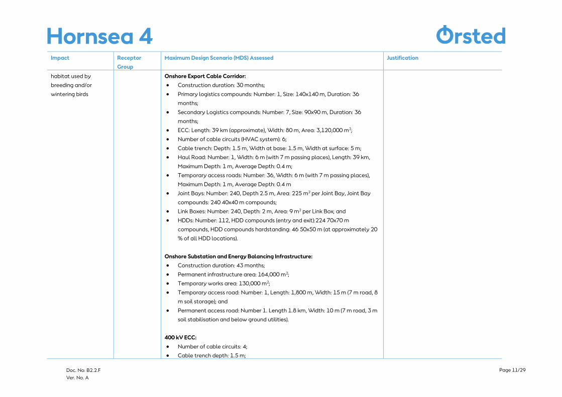
Impacts on breeding
and/or wintering bird
species: Construction
activities will
temporarily occupy
areas leading to loss
and/or degradation of
Ecology and
Nature
Conservation
Landfall:
• Construction duration: 32 months;
• Landfall compound: Number: 1, Total Area: 40,000 m2, Duration: 32 months;
and
• Transition Joint Bays (located within Landfall compound area): Number: 8,
Depth: 6 m.
These parameters represent maximum
ground disturbance conditions both in
terms of potential size of area affected and
in terms of duration of expected
disturbance.
Page 11/29
Doc. No: B2.2.F
Ver. No. A
Impact Receptor
Group
Maximum Design Scenario (MDS) Assessed Justification
habitat used by
breeding and/or
wintering birds
Onshore Export Cable Corridor:
• Construction duration: 30 months;
• Primary logistics compounds: Number: 1, Size: 140x140 m, Duration: 36
months;
• Secondary Logistics compounds: Number: 7, Size: 90x90 m, Duration: 36
months;
• ECC: Length: 39 km (approximate), Width: 80 m, Area: 3,120,000 m2;
• Number of cable circuits (HVAC system): 6;
• Cable trench: Depth: 1.5 m, Width at base: 1.5 m, Width at surface: 5 m;
• Haul Road: Number: 1, Width: 6 m (with 7 m passing places), Length: 39 km,
Maximum Depth: 1 m, Average Depth: 0.4 m;
• Temporary access roads: Number: 36, Width: 6 m (with 7 m passing places),
Maximum Depth: 1 m, Average Depth: 0.4 m
• Joint Bays: Number: 240, Depth 2.5 m, Area: 225 m2 per Joint Bay, Joint Bay
compounds: 240 40x40 m compounds;
• Link Boxes: Number: 240, Depth: 2 m, Area: 9 m2 per Link Box; and
• HDDs: Number: 112, HDD compounds (entry and exit):224 70x70 m
compounds, HDD compounds hardstanding: 46 50x50 m (at approximately 20
% of all HDD locations).
Onshore Substation and Energy Balancing Infrastructure:
• Construction duration: 43 months;
• Permanent infrastructure area: 164,000 m2;
• Temporary works area: 130,000 m2;
• Temporary access road: Number: 1, Length: 1,800 m, Width: 15 m (7 m road, 8
m soil storage); and
• Permanent access road: Number 1. Length 1.8 km, Width: 10 m (7 m road, 3 m
soil stabilisation and below ground utilities).
400 kV ECC:
• Number of cable circuits: 4;
• Cable trench depth: 1.5 m;
Page 12/29
Doc. No: B2.2.F
Ver. No. A
Impact Receptor
Group
Maximum Design Scenario (MDS) Assessed Justification
• Approximate Length: 1 km; and
• Width: 60 m.
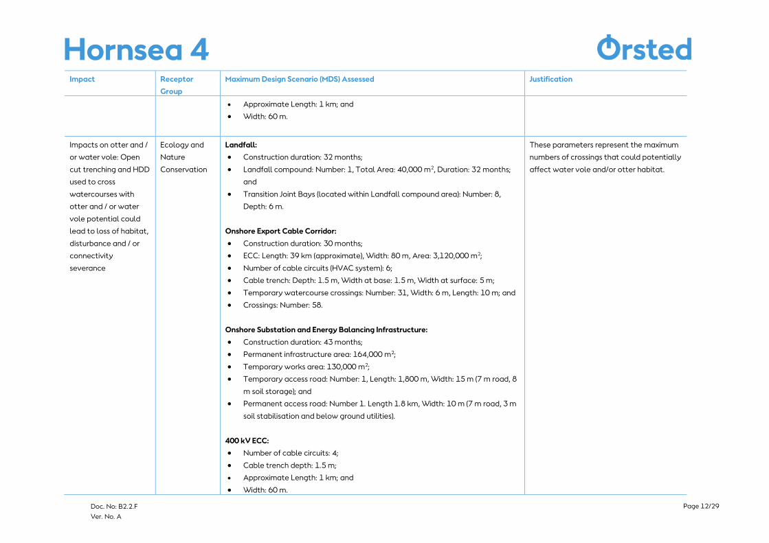
Impacts on otter and /
or water vole: Open
cut trenching and HDD
used to cross
watercourses with
otter and / or water
vole potential could
lead to loss of habitat,
disturbance and / or
connectivity
severance
Ecology and
Nature
Conservation
Landfall:
• Construction duration: 32 months;
• Landfall compound: Number: 1, Total Area: 40,000 m2, Duration: 32 months;
and
• Transition Joint Bays (located within Landfall compound area): Number: 8,
Depth: 6 m.
Onshore Export Cable Corridor:
• Construction duration: 30 months;
• ECC: Length: 39 km (approximate), Width: 80 m, Area: 3,120,000 m2;
• Number of cable circuits (HVAC system): 6;
• Cable trench: Depth: 1.5 m, Width at base: 1.5 m, Width at surface: 5 m;
• Temporary watercourse crossings: Number: 31, Width: 6 m, Length: 10 m; and
• Crossings: Number: 58.
Onshore Substation and Energy Balancing Infrastructure:
• Construction duration: 43 months;
• Permanent infrastructure area: 164,000 m2;
• Temporary works area: 130,000 m2;
• Temporary access road: Number: 1, Length: 1,800 m, Width: 15 m (7 m road, 8
m soil storage); and
• Permanent access road: Number 1. Length 1.8 km, Width: 10 m (7 m road, 3 m
soil stabilisation and below ground utilities).
400 kV ECC:
• Number of cable circuits: 4;
• Cable trench depth: 1.5 m;
• Approximate Length: 1 km; and
• Width: 60 m.
These parameters represent the maximum
numbers of crossings that could potentially
affect water vole and/or otter habitat.
Page 13/29
Doc. No: B2.2.F
Ver. No. A
Impact Receptor
Group
Maximum Design Scenario (MDS) Assessed Justification
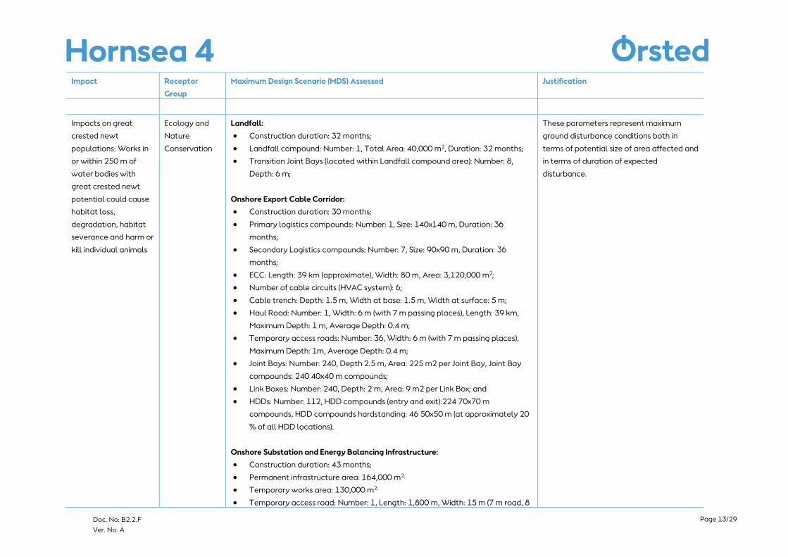
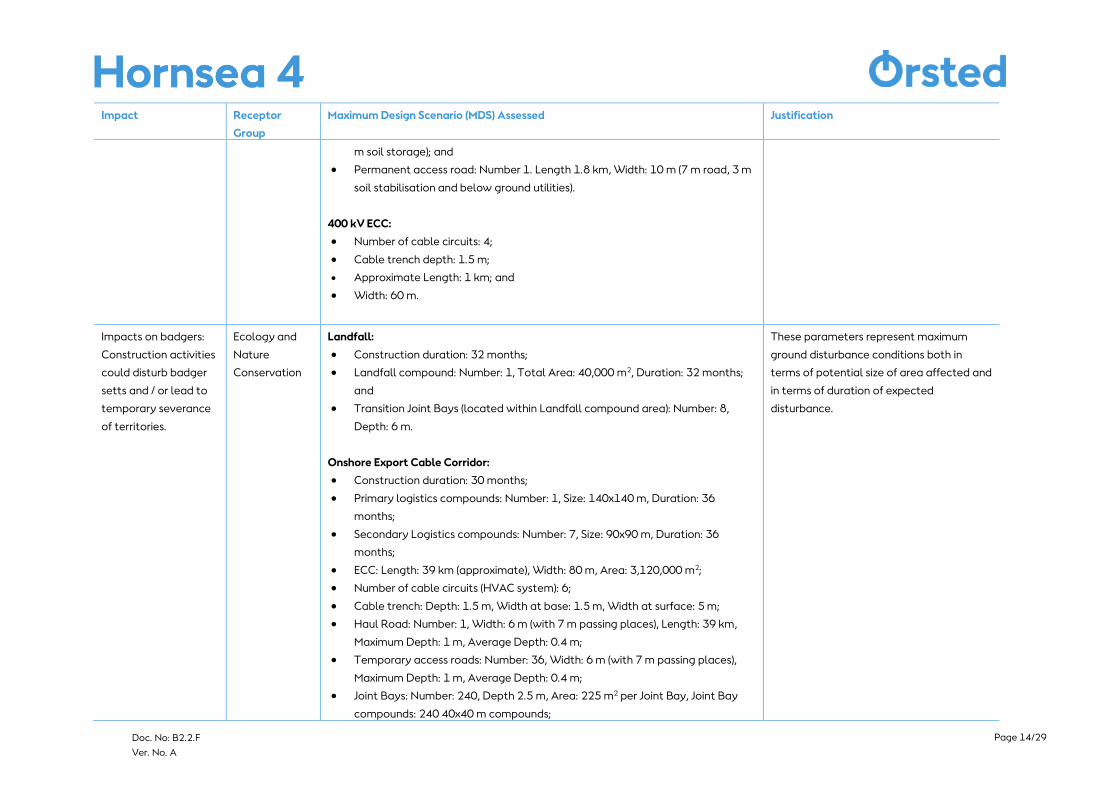
Impacts on great
crested newt
populations: Works in
or within 250 m of
water bodies with
great crested newt
potential could cause
habitat loss,
degradation, habitat
severance and harm or
kill individual animals
Ecology and
Nature
Conservation
Landfall:
• Construction duration: 32 months;
• Landfall compound: Number: 1, Total Area: 40,000 m2, Duration: 32 months;
• Transition Joint Bays (located within Landfall compound area): Number: 8,
Depth: 6 m;
Onshore Export Cable Corridor:
• Construction duration: 30 months;
• Primary logistics compounds: Number: 1, Size: 140x140 m, Duration: 36
months;
• Secondary Logistics compounds: Number: 7, Size: 90x90 m, Duration: 36
months;
• ECC: Length: 39 km (approximate), Width: 80 m, Area: 3,120,000 m2;
• Number of cable circuits (HVAC system): 6;
• Cable trench: Depth: 1.5 m, Width at base: 1.5 m, Width at surface: 5 m;
• Haul Road: Number: 1, Width: 6 m (with 7 m passing places), Length: 39 km,
Maximum Depth: 1 m, Average Depth: 0.4 m;
• Temporary access roads: Number: 36, Width: 6 m (with 7 m passing places),
Maximum Depth: 1m, Average Depth: 0.4 m;
• Joint Bays: Number: 240, Depth 2.5 m, Area: 225 m2 per Joint Bay, Joint Bay
compounds: 240 40x40 m compounds;
• Link Boxes: Number: 240, Depth: 2 m, Area: 9 m2 per Link Box; and
• HDDs: Number: 112, HDD compounds (entry and exit):224 70x70 m
compounds, HDD compounds hardstanding: 46 50x50 m (at approximately 20
% of all HDD locations).
Onshore Substation and Energy Balancing Infrastructure:
• Construction duration: 43 months;
• Permanent infrastructure area: 164,000 m2;
• Temporary works area: 130,000 m2;
• Temporary access road: Number: 1, Length: 1,800 m, Width: 15 m (7 m road, 8
These parameters represent maximum
ground disturbance conditions both in
terms of potential size of area affected and
in terms of duration of expected
disturbance.
Page 14/29
Doc. No: B2.2.F
Ver. No. A
Impact Receptor
Group
Maximum Design Scenario (MDS) Assessed Justification
m soil storage); and
• Permanent access road: Number 1. Length 1.8 km, Width: 10 m (7 m road, 3 m
soil stabilisation and below ground utilities).
400 kV ECC:
• Number of cable circuits: 4;
• Cable trench depth: 1.5 m;
• Approximate Length: 1 km; and
• Width: 60 m.
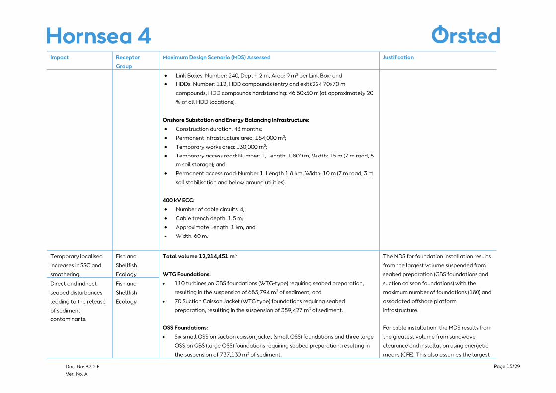
Impacts on badgers:
Construction activities
could disturb badger
setts and / or lead to
temporary severance
of territories.
Ecology and
Nature
Conservation
Landfall:
• Construction duration: 32 months;
• Landfall compound: Number: 1, Total Area: 40,000 m2, Duration: 32 months;
and
• Transition Joint Bays (located within Landfall compound area): Number: 8,
Depth: 6 m.
Onshore Export Cable Corridor:
• Construction duration: 30 months;
• Primary logistics compounds: Number: 1, Size: 140x140 m, Duration: 36
months;
• Secondary Logistics compounds: Number: 7, Size: 90x90 m, Duration: 36
months;
• ECC: Length: 39 km (approximate), Width: 80 m, Area: 3,120,000 m2;
• Number of cable circuits (HVAC system): 6;
• Cable trench: Depth: 1.5 m, Width at base: 1.5 m, Width at surface: 5 m;
• Haul Road: Number: 1, Width: 6 m (with 7 m passing places), Length: 39 km,
Maximum Depth: 1 m, Average Depth: 0.4 m;
• Temporary access roads: Number: 36, Width: 6 m (with 7 m passing places),
Maximum Depth: 1 m, Average Depth: 0.4 m;
• Joint Bays: Number: 240, Depth 2.5 m, Area: 225 m2 per Joint Bay, Joint Bay
compounds: 240 40x40 m compounds;
These parameters represent maximum
ground disturbance conditions both in
terms of potential size of area affected and
in terms of duration of expected
disturbance.
Page 15/29
Doc. No: B2.2.F
Ver. No. A
Impact Receptor
Group
Maximum Design Scenario (MDS) Assessed Justification
• Link Boxes: Number: 240, Depth: 2 m, Area: 9 m2 per Link Box; and
• HDDs: Number: 112, HDD compounds (entry and exit):224 70x70 m
compounds, HDD compounds hardstanding: 46 50x50 m (at approximately 20
% of all HDD locations).
Onshore Substation and Energy Balancing Infrastructure:
• Construction duration: 43 months;
• Permanent infrastructure area: 164,000 m2;
• Temporary works area: 130,000 m2;
• Temporary access road: Number: 1, Length: 1,800 m, Width: 15 m (7 m road, 8
m soil storage); and
• Permanent access road: Number 1. Length 1.8 km, Width: 10 m (7 m road, 3 m
soil stabilisation and below ground utilities).
400 kV ECC:
• Number of cable circuits: 4;
• Cable trench depth: 1.5 m;
• Approximate Length: 1 km; and
• Width: 60 m.
Temporary localised
increases in SSC and
smothering.
Fish and
Shellfish
Ecology
Total volume 12,214,451 m3
WTG Foundations:
• 110 turbines on GBS foundations (WTG-type) requiring seabed preparation,
resulting in the suspension of 685,794 m3 of sediment; and
• 70 Suction Caisson Jacket (WTG type) foundations requiring seabed
preparation, resulting in the suspension of 359,427 m3 of sediment.
OSS Foundations:
• Six small OSS on suction caisson jacket (small OSS) foundations and three large
OSS on GBS (large OSS) foundations requiring seabed preparation, resulting in
the suspension of 737,130 m3 of sediment.
The MDS for foundation installation results
from the largest volume suspended from
seabed preparation (GBS foundations and
suction caisson foundations) with the
maximum number of foundations (180) and
associated offshore platform
infrastructure.
For cable installation, the MDS results from
the greatest volume from sandwave
clearance and installation using energetic
means (CFE). This also assumes the largest
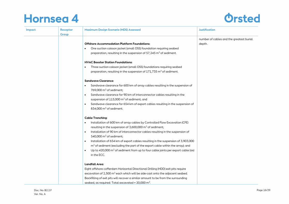
Direct and indirect
seabed disturbances
leading to the release
of sediment
contaminants.
Fish and
Shellfish
Ecology
Page 16/29
Doc. No: B2.2.F
Ver. No. A
Impact Receptor
Group
Maximum Design Scenario (MDS) Assessed Justification
Offshore Accommodation Platform Foundations:
• One suction caisson jacket (small OSS) foundation requiring seabed
preparation, resulting in the suspension of 57,245 m3 of sediment.
HVAC Booster Station Foundations:
• Three suction caisson jacket (small OSS) foundations requiring seabed
preparation, resulting in the suspension of 171,735 m3 of sediment.
Sandwave Clearance:
• Sandwave clearance for 600 km of array cables resulting in the suspension of
769,000 m3 of sediment;
• Sandwave clearance for 90 km of interconnector cables resulting in the
suspension of 115,000 m3 of sediment; and
• Sandwave clearance for 654 km of export cables resulting in the suspension of
834,000 m3 of sediment.
Cable Trenching:
• Installation of 600 km of array cables by Controlled Flow Excavation (CFE)
resulting in the suspension of 3,600,000 m3 of sediment;
• Installation of 90 km of interconnector cables resulting in the suspension of
540,000 m3 of sediment;
• Installation of 654 km of export cables resulting in the suspension of 3,903,000
m3 of sediment (excluding the part of the export cable within the array); and
• Up to 420,000 m3 of sediment from up to four cable joints per export cable (six)
in the ECC.
Landfall Area:
Eight offshore cofferdam Horizontal Directional Drilling (HDD) exit pits require
excavation of 2,500 m3 each which will be side-cast onto the adjacent seabed.
Backfilling of exit pits will recover a similar amount to be from the surrounding
seabed, as required. Total excavated = 20,000 m3.
number of cables and the greatest burial
depth.
Page 17/29
Doc. No: B2.2.F
Ver. No. A
Impact Receptor
Group
Maximum Design Scenario (MDS) Assessed Justification
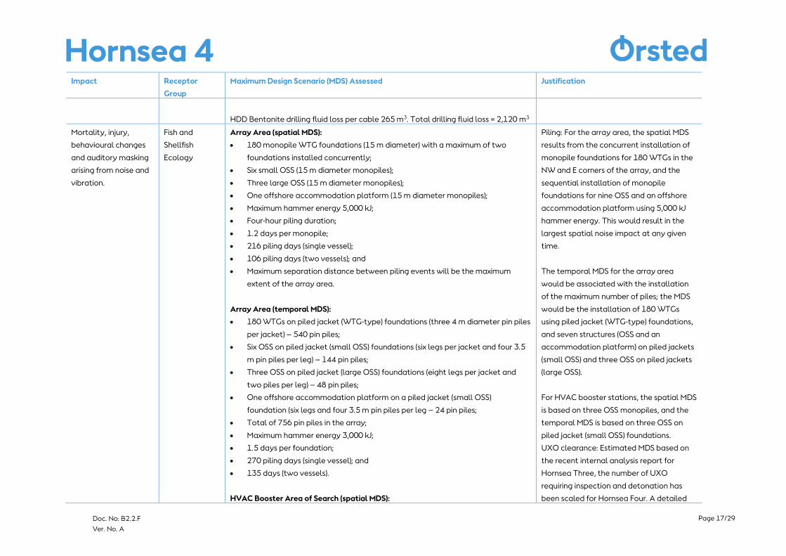
HDD Bentonite drilling fluid loss per cable 265 m3. Total drilling fluid loss = 2,120 m3
Mortality, injury,
behavioural changes
and auditory masking
arising from noise and
vibration.
Fish and
Shellfish
Ecology
Array Area (spatial MDS):
• 180 monopile WTG foundations (15 m diameter) with a maximum of two
foundations installed concurrently;
• Six small OSS (15 m diameter monopiles);
• Three large OSS (15 m diameter monopiles);
• One offshore accommodation platform (15 m diameter monopiles);
• Maximum hammer energy 5,000 kJ;
• Four-hour piling duration;
• 1.2 days per monopile;
• 216 piling days (single vessel);
• 106 piling days (two vessels); and
• Maximum separation distance between piling events will be the maximum
extent of the array area.
Array Area (temporal MDS):
• 180 WTGs on piled jacket (WTG-type) foundations (three 4 m diameter pin piles
per jacket) – 540 pin piles;
• Six OSS on piled jacket (small OSS) foundations (six legs per jacket and four 3.5
m pin piles per leg) – 144 pin piles;
• Three OSS on piled jacket (large OSS) foundations (eight legs per jacket and
two piles per leg) – 48 pin piles;
• One offshore accommodation platform on a piled jacket (small OSS)
foundation (six legs and four 3.5 m pin piles per leg – 24 pin piles;
• Total of 756 pin piles in the array;
• Maximum hammer energy 3,000 kJ;
• 1.5 days per foundation;
• 270 piling days (single vessel); and
• 135 days (two vessels).
HVAC Booster Area of Search (spatial MDS):
Piling: For the array area, the spatial MDS
results from the concurrent installation of
monopile foundations for 180 WTGs in the
NW and E corners of the array, and the
sequential installation of monopile
foundations for nine OSS and an offshore
accommodation platform using 5,000 kJ
hammer energy. This would result in the
largest spatial noise impact at any given
time.
The temporal MDS for the array area
would be associated with the installation
of the maximum number of piles; the MDS
would be the installation of 180 WTGs
using piled jacket (WTG-type) foundations,
and seven structures (OSS and an
accommodation platform) on piled jackets
(small OSS) and three OSS on piled jackets
(large OSS).
For HVAC booster stations, the spatial MDS
is based on three OSS monopiles, and the
temporal MDS is based on three OSS on
piled jacket (small OSS) foundations.
UXO clearance: Estimated MDS based on
the recent internal analysis report for
Hornsea Three, the number of UXO
requiring inspection and detonation has
been scaled for Hornsea Four. A detailed
Page 18/29
Doc. No: B2.2.F
Ver. No. A
Impact Receptor
Group
Maximum Design Scenario (MDS) Assessed Justification
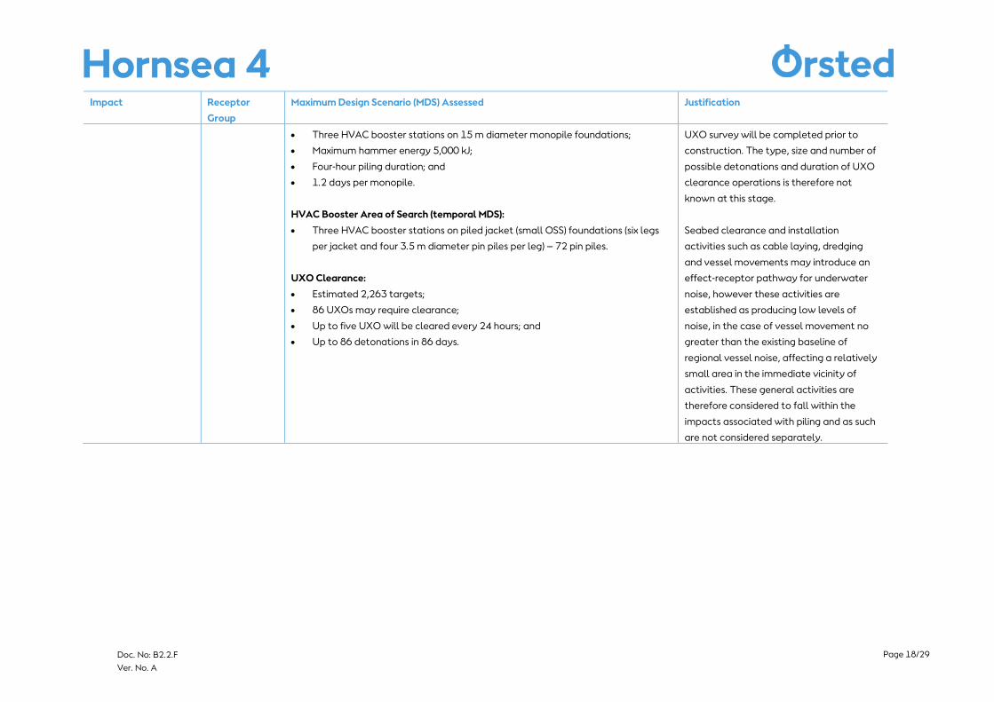
• Three HVAC booster stations on 15 m diameter monopile foundations;
• Maximum hammer energy 5,000 kJ;
• Four-hour piling duration; and
• 1.2 days per monopile.
HVAC Booster Area of Search (temporal MDS):
• Three HVAC booster stations on piled jacket (small OSS) foundations (six legs
per jacket and four 3.5 m diameter pin piles per leg) – 72 pin piles.
UXO Clearance:
• Estimated 2,263 targets;
• 86 UXOs may require clearance;
• Up to five UXO will be cleared every 24 hours; and
• Up to 86 detonations in 86 days.
UXO survey will be completed prior to
construction. The type, size and number of
possible detonations and duration of UXO
clearance operations is therefore not
known at this stage.
Seabed clearance and installation
activities such as cable laying, dredging
and vessel movements may introduce an
effect-receptor pathway for underwater
noise, however these activities are
established as producing low levels of
noise, in the case of vessel movement no
greater than the existing baseline of
regional vessel noise, affecting a relatively
small area in the immediate vicinity of
activities. These general activities are
therefore considered to fall within the
impacts associated with piling and as such
are not considered separately.
Page 19/29
Doc. No: B2.2.F
Ver. No. A
Impact Receptor
Group
Maximum Design Scenario (MDS) Assessed Justification
Operation and Maintenance
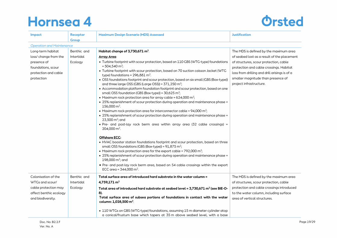
Long-term habitat
loss/ change from the
presence of
foundations, scour
protection and cable
protection
Benthic and
Intertidal
Ecology
Habitat change of 3,730,671 m2.
Array Area:
• Turbine footprint with scour protection, based on 110 GBS (WTG-type) foundations
= 504,540 m2;
• Turbine footprint with scour protection, based on 70 suction caisson Jacket (WTG
type) foundations = 296,881 m2.
• OSS foundations footprint and scour protection, based on six small (GBS (Box-type))
and three large OSS (GBS (Large OSS)) = 371,250 m2;
• Accommodation platform foundation footprint and scour protection, based on one
small OSS foundation (GBS (Box-type)) = 30,625 m2;
• Maximum rock protection area for array cable = 624,000 m2;
• 25% replenishment of scour protection during operation and maintenance phase =
156,000 m2.
• Maximum rock protection area for interconnector cable = 94,000 m2;
• 25% replenishment of scour protection during operation and maintenance phase =
23,500 m2; and
• Pre- and post-lay rock berm area within array area (32 cable crossings) =
204,000 m2.
Offshore ECC:
• HVAC booster station foundations footprint and scour protection, based on three
small OSS foundations (GBS (Box-type)) = 91,875 m2;
• Maximum rock protection area for the export cable = 792,000 m2;
• 25% replenishment of scour protection during operation and maintenance phase =
198,000 m2; and
• Pre- and post-lay rock berm area, based on 54 cable crossings within the export
ECC area = 344,000 m2.
The MDS is defined by the maximum area
of seabed lost as a result of the placement
of structures, scour protection, cable
protection and cable crossings. Habitat
loss from drilling and drill arisings is of a
smaller magnitude than presence of
project infrastructure.
Colonisation of the
WTGs and scour/
cable protection may
affect benthic ecology
and biodiversity.
Benthic and
Intertidal
Ecology
Total surface area of introduced hard substrate in the water column =
4,759,171 m2
Total area of introduced hard substrate at seabed level = 3,730,671 m2 (see BIE-O-
8).
Total surface area of subsea portions of foundations in contact with the water
column: 1,028,500 m2.
• 110 WTGs on GBS (WTG-type) foundations, assuming 15 m diameter cylinder atop
a conical/frustum base which tapers at 35 m above seabed level, with a base
The MDS is defined by the maximum area
of structures, scour protection, cable
protection and cable crossings introduced
to the water column, including surface
area of vertical structures.
Page 20/29
Doc. No: B2.2.F
Ver. No. A
Impact Receptor
Group
Maximum Design Scenario (MDS) Assessed Justification
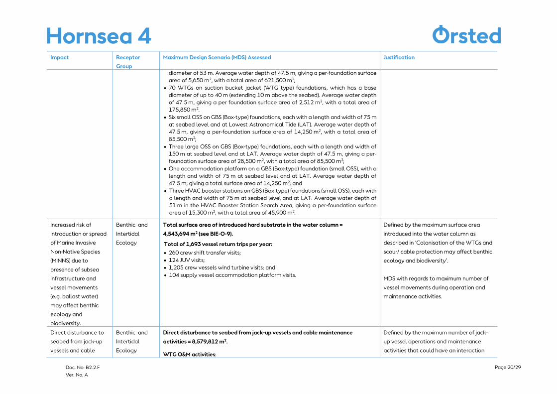
diameter of 53 m. Average water depth of 47.5 m, giving a per-foundation surface
area of 5,650 m2, with a total area of 621,500 m2;
• 70 WTGs on suction bucket jacket (WTG type) foundations, which has a base
diameter of up to 40 m (extending 10 m above the seabed). Average water depth
of 47.5 m, giving a per foundation surface area of 2,512 m2, with a total area of
175,850 m2.
• Six small OSS on GBS (Box-type) foundations, each with a length and width of 75 m
at seabed level and at Lowest Astronomical Tide (LAT). Average water depth of
47.5 m, giving a per-foundation surface area of 14,250 m2, with a total area of
85,500 m2;
• Three large OSS on GBS (Box-type) foundations, each with a length and width of
150 m at seabed level and at LAT. Average water depth of 47.5 m, giving a per-
foundation surface area of 28,500 m2, with a total area of 85,500 m2;
• One accommodation platform on a GBS (Box-type) foundation (small OSS), with a
length and width of 75 m at seabed level and at LAT. Average water depth of
47.5 m, giving a total surface area of 14,250 m2; and
• Three HVAC booster stations on GBS (Box-type) foundations (small OSS), each with
a length and width of 75 m at seabed level and at LAT. Average water depth of
51 m in the HVAC Booster Station Search Area, giving a per-foundation surface
area of 15,300 m2, with a total area of 45,900 m2.
Increased risk of
introduction or spread
of Marine Invasive
Non-Native Species
(MINNS) due to
presence of subsea
infrastructure and
vessel movements
(e.g. ballast water)
may affect benthic
ecology and
biodiversity.
Benthic and
Intertidal
Ecology
Total surface area of introduced hard substrate in the water column =
4,543,694 m2 (see BIE-O-9).
Total of 1,693 vessel return trips per year:
• 260 crew shift transfer visits;
• 124 JUV visits;
• 1,205 crew vessels wind turbine visits; and
• 104 supply vessel accommodation platform visits.
Defined by the maximum surface area
introduced into the water column as
described in ‘Colonisation of the WTGs and
scour/ cable protection may affect benthic
ecology and biodiversity’.
MDS with regards to maximum number of
vessel movements during operation and
maintenance activities.
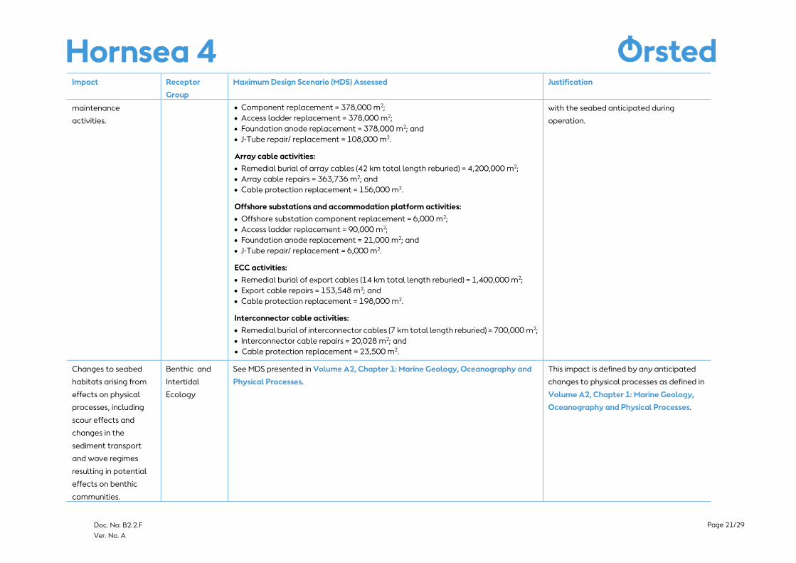
Direct disturbance to
seabed from jack-up
vessels and cable
Benthic and
Intertidal
Ecology
Direct disturbance to seabed from jack-up vessels and cable maintenance
activities = 8,579,812 m2.
WTG O&M activities:
Defined by the maximum number of jack-
up vessel operations and maintenance
activities that could have an interaction
Page 21/29
Doc. No: B2.2.F
Ver. No. A
Impact Receptor
Group
Maximum Design Scenario (MDS) Assessed Justification
maintenance
activities.
• Component replacement = 378,000 m2;
• Access ladder replacement = 378,000 m2;
• Foundation anode replacement = 378,000 m2; and
• J-Tube repair/ replacement = 108,000 m2.
Array cable activities:
• Remedial burial of array cables (42 km total length reburied) = 4,200,000 m2;
• Array cable repairs = 363,736 m2; and
• Cable protection replacement = 156,000 m2.
Offshore substations and accommodation platform activities:
• Offshore substation component replacement = 6,000 m2;
• Access ladder replacement = 90,000 m2;
• Foundation anode replacement = 21,000 m2; and
• J-Tube repair/ replacement = 6,000 m2.
ECC activities:
• Remedial burial of export cables (14 km total length reburied) = 1,400,000 m2;
• Export cable repairs = 153,548 m2; and
• Cable protection replacement = 198,000 m2.
Interconnector cable activities:
• Remedial burial of interconnector cables (7 km total length reburied) = 700,000 m2;
• Interconnector cable repairs = 20,028 m2; and
• Cable protection replacement = 23,500 m2.
with the seabed anticipated during
operation.
Changes to seabed
habitats arising from
effects on physical
processes, including
scour effects and
changes in the
sediment transport
and wave regimes
resulting in potential
effects on benthic
communities.
Benthic and
Intertidal
Ecology
See MDS presented in Volume A2, Chapter 1: Marine Geology, Oceanography and
Physical Processes.
This impact is defined by any anticipated
changes to physical processes as defined in
Volume A2, Chapter 1: Marine Geology,
Oceanography and Physical Processes.
Page 22/29
Doc. No: B2.2.F
Ver. No. A
Impact Receptor
Group
Maximum Design Scenario (MDS) Assessed Justification
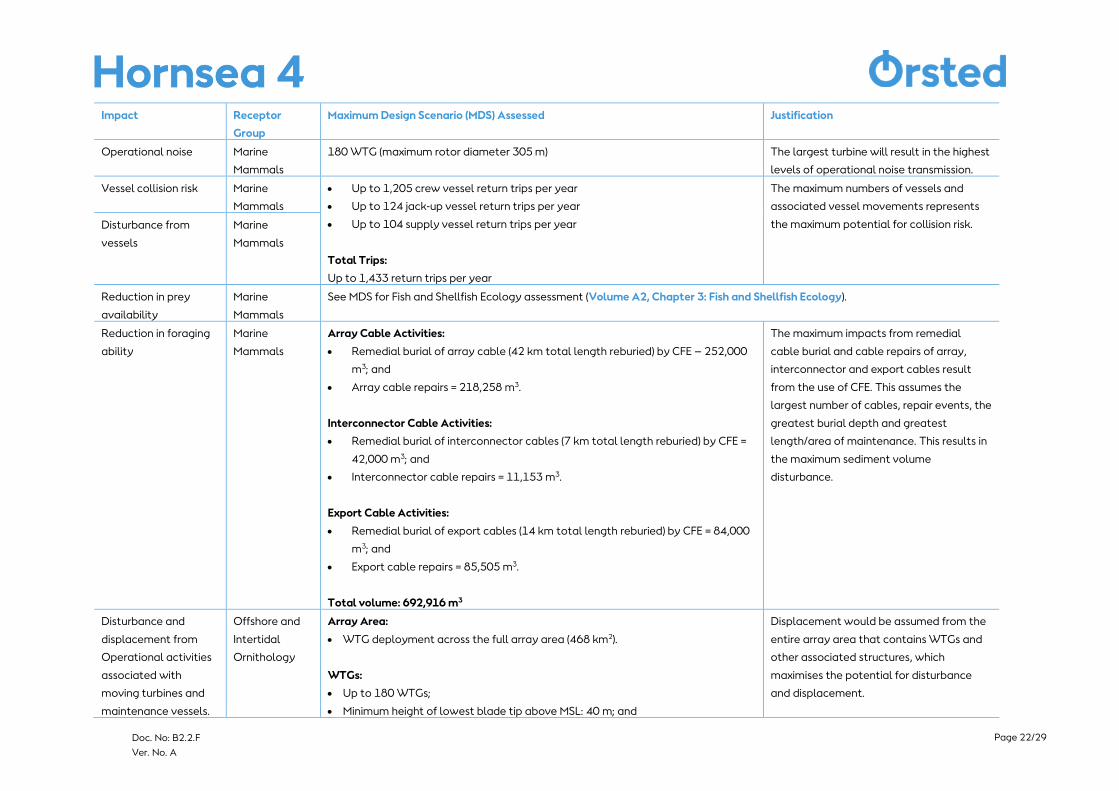
Operational noise Marine
Mammals
180 WTG (maximum rotor diameter 305 m) The largest turbine will result in the highest
levels of operational noise transmission.
Vessel collision risk Marine
Mammals
• Up to 1,205 crew vessel return trips per year
• Up to 124 jack-up vessel return trips per year
• Up to 104 supply vessel return trips per year
Total Trips:
Up to 1,433 return trips per year
The maximum numbers of vessels and
associated vessel movements represents
the maximum potential for collision risk. Disturbance from
vessels
Marine
Mammals
Reduction in prey
availability
Marine
Mammals
See MDS for Fish and Shellfish Ecology assessment (Volume A2, Chapter 3: Fish and Shellfish Ecology).
Reduction in foraging
ability
Marine
Mammals
Array Cable Activities:
• Remedial burial of array cable (42 km total length reburied) by CFE – 252,000
m3; and
• Array cable repairs = 218,258 m3.
Interconnector Cable Activities:
• Remedial burial of interconnector cables (7 km total length reburied) by CFE =
42,000 m3; and
• Interconnector cable repairs = 11,153 m3.
Export Cable Activities:
• Remedial burial of export cables (14 km total length reburied) by CFE = 84,000
m3; and
• Export cable repairs = 85,505 m3.
Total volume: 692,916 m3
The maximum impacts from remedial
cable burial and cable repairs of array,
interconnector and export cables result
from the use of CFE. This assumes the
largest number of cables, repair events, the
greatest burial depth and greatest
length/area of maintenance. This results in
the maximum sediment volume
disturbance.
Disturbance and
displacement from
Operational activities
associated with
moving turbines and
maintenance vessels.
Offshore and
Intertidal
Ornithology
Array Area:
• WTG deployment across the full array area (468 km2).
WTGs:
• Up to 180 WTGs;
• Minimum height of lowest blade tip above MSL: 40 m; and
Displacement would be assumed from the
entire array area that contains WTGs and
other associated structures, which
maximises the potential for disturbance
and displacement.
Page 23/29
Doc. No: B2.2.F
Ver. No. A
Impact Receptor
Group
Maximum Design Scenario (MDS) Assessed Justification
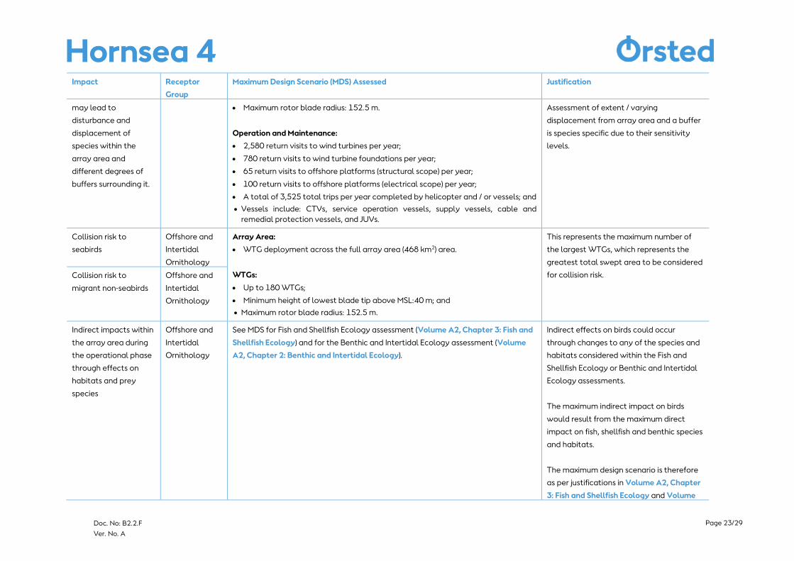
may lead to
disturbance and
displacement of
species within the
array area and
different degrees of
buffers surrounding it.
• Maximum rotor blade radius: 152.5 m.
Operation and Maintenance:
• 2,580 return visits to wind turbines per year;
• 780 return visits to wind turbine foundations per year;
• 65 return visits to offshore platforms (structural scope) per year;
• 100 return visits to offshore platforms (electrical scope) per year;
• A total of 3,525 total trips per year completed by helicopter and / or vessels; and
• Vessels include: CTVs, service operation vessels, supply vessels, cable and
remedial protection vessels, and JUVs.
Assessment of extent / varying
displacement from array area and a buffer
is species specific due to their sensitivity
levels.
Collision risk to
seabirds
Offshore and
Intertidal
Ornithology
Array Area:
• WTG deployment across the full array area (468 km2) area.
WTGs:
• Up to 180 WTGs;
• Minimum height of lowest blade tip above MSL:40 m; and
• Maximum rotor blade radius: 152.5 m.
This represents the maximum number of
the largest WTGs, which represents the
greatest total swept area to be considered
for collision risk. Collision risk to
migrant non-seabirds
Offshore and
Intertidal
Ornithology
Indirect impacts within
the array area during
the operational phase
through effects on
habitats and prey
species
Offshore and
Intertidal
Ornithology
See MDS for Fish and Shellfish Ecology assessment (Volume A2, Chapter 3: Fish and
Shellfish Ecology) and for the Benthic and Intertidal Ecology assessment (Volume
A2, Chapter 2: Benthic and Intertidal Ecology).
Indirect effects on birds could occur
through changes to any of the species and
habitats considered within the Fish and
Shellfish Ecology or Benthic and Intertidal
Ecology assessments.
The maximum indirect impact on birds
would result from the maximum direct
impact on fish, shellfish and benthic species
and habitats.
The maximum design scenario is therefore
as per justifications in Volume A2, Chapter
3: Fish and Shellfish Ecology and Volume
Page 24/29
Doc. No: B2.2.F
Ver. No. A
Impact Receptor
Group
Maximum Design Scenario (MDS) Assessed Justification
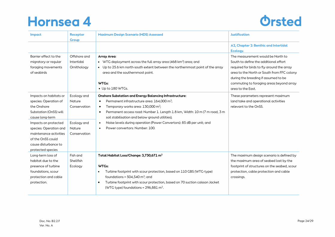
A2, Chapter 2: Benthic and Intertidal
Ecology.
Barrier effect to the
migratory or regular
foraging movements
of seabirds
Offshore and
Intertidal
Ornithology
Array Area:
• WTG deployment across the full array area (468 km2) area; and
• Up to 25.6 km north-south extent between the northernmost point of the array
area and the southernmost point.
WTGs:
• Up to 180 WTGs.
The measurement would be North to
South to define the additional effort
required for birds to fly around the array
area to the North or South from FFC colony
during the breeding if assumed to be
commuting to foraging areas beyond array
area to the East.
Impacts on habitats or
species: Operation of
the Onshore
Substation (OnSS) will
cause long-term
Ecology and
Nature
Conservation
Onshore Substation and Energy Balancing Infrastructure:
• Permanent infrastructure area: 164,000 m2;
• Temporary works area: 130,000 m2;
• Permanent access road: Number 1. Length 1.8 km, Width: 10 m (7 m road, 3 m
soil stabilisation and below ground utilities);
• Noise levels during operation (Power Convertors): 85 dB per unit; and
• Power convertors: Number: 100.
These parameters represent maximum
land take and operational activities
relevant to the OnSS.
Impacts on protected
species: Operation and
maintenance activities
of the OnSS could
cause disturbance to
protected species
Ecology and
Nature
Conservation
Long-term loss of
habitat due to the
presence of turbine
foundations, scour
protection and cable
protection.
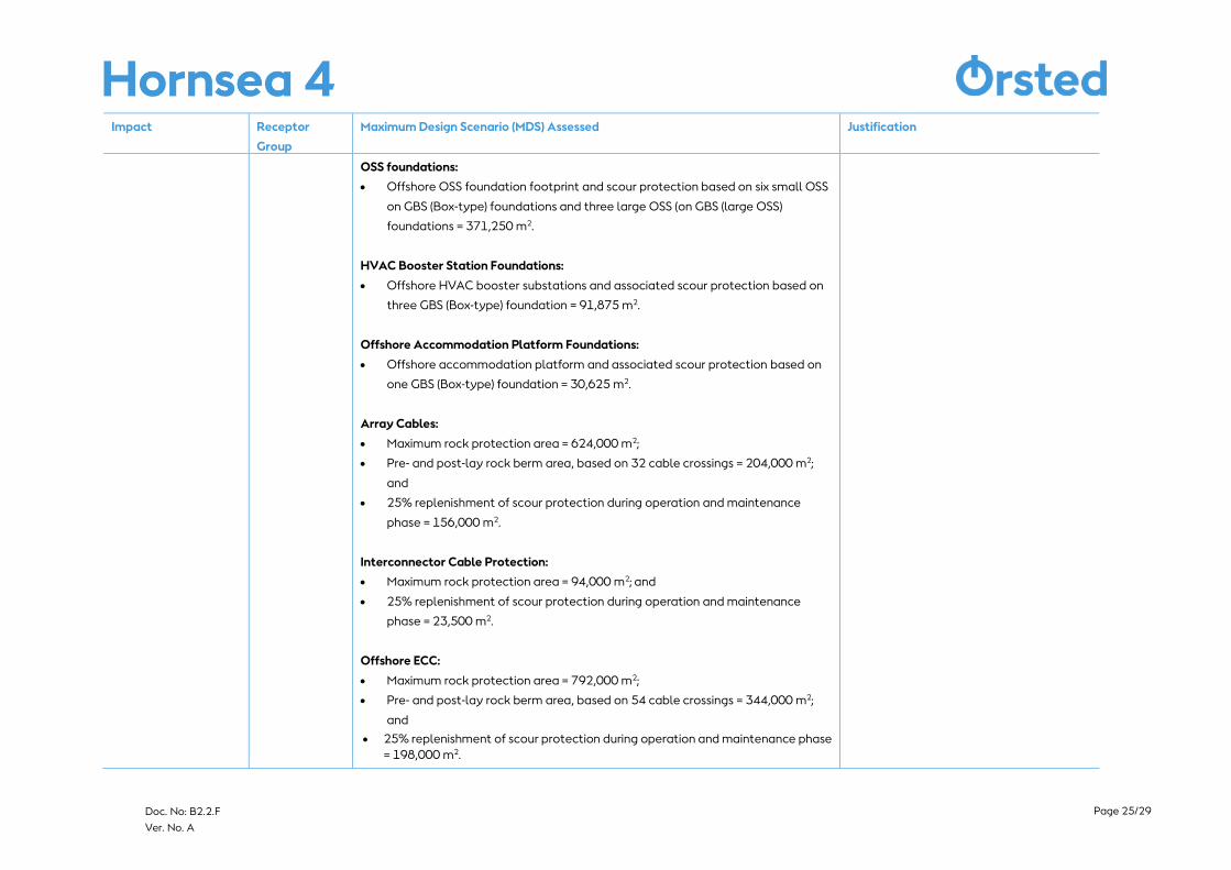
Fish and
Shellfish
Ecology
Total Habitat Loss/Change: 3,730,671 m2
WTGs:
• Turbine footprint with scour protection, based on 110 GBS (WTG-type)
foundations = 504,540 m2; and
• Turbine footprint with scour protection, based on 70 suction caisson Jacket
(WTG type) foundations = 296,881 m2.
The maximum design scenario is defined by
the maximum area of seabed lost by the
footprint of structures on the seabed, scour
protection, cable protection and cable
crossings.
Page 25/29
Doc. No: B2.2.F
Ver. No. A
Impact Receptor
Group
Maximum Design Scenario (MDS) Assessed Justification
OSS foundations:
• Offshore OSS foundation footprint and scour protection based on six small OSS
on GBS (Box-type) foundations and three large OSS (on GBS (large OSS)
foundations = 371,250 m2.
HVAC Booster Station Foundations:
• Offshore HVAC booster substations and associated scour protection based on
three GBS (Box-type) foundation = 91,875 m2.
Offshore Accommodation Platform Foundations:
• Offshore accommodation platform and associated scour protection based on
one GBS (Box-type) foundation = 30,625 m2.
Array Cables:
• Maximum rock protection area = 624,000 m2;
• Pre- and post-lay rock berm area, based on 32 cable crossings = 204,000 m2;
and
• 25% replenishment of scour protection during operation and maintenance
phase = 156,000 m2.
Interconnector Cable Protection:
• Maximum rock protection area = 94,000 m2; and
• 25% replenishment of scour protection during operation and maintenance
phase = 23,500 m2.
Offshore ECC:
• Maximum rock protection area = 792,000 m2;
• Pre- and post-lay rock berm area, based on 54 cable crossings = 344,000 m2;
and
• 25% replenishment of scour protection during operation and maintenance phase
= 198,000 m2.
Page 26/29
Doc. No: B2.2.F
Ver. No. A
Impact Receptor
Group
Maximum Design Scenario (MDS) Assessed Justification
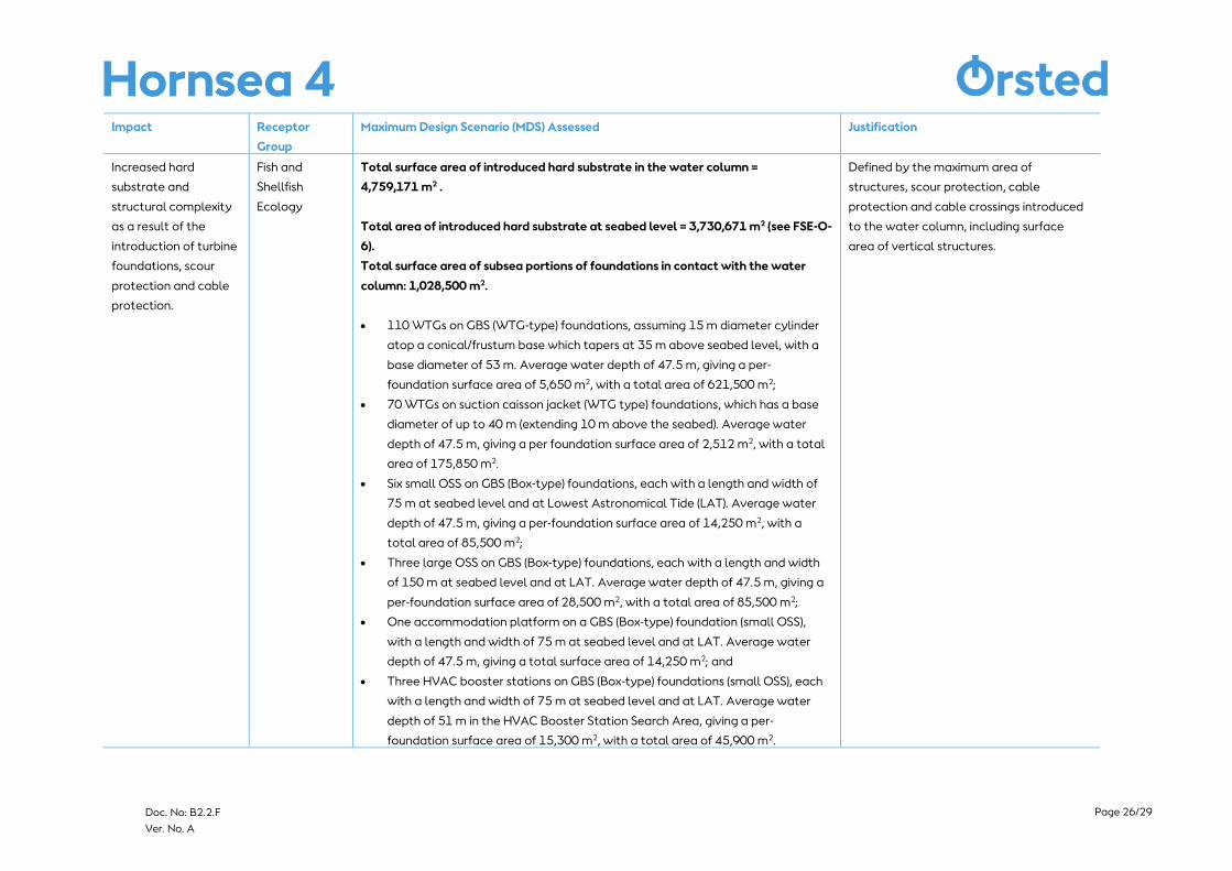
Increased hard
substrate and
structural complexity
as a result of the
introduction of turbine
foundations, scour
protection and cable
protection.
Fish and
Shellfish
Ecology
Total surface area of introduced hard substrate in the water column =
4,759,171 m2 .
Total area of introduced hard substrate at seabed level = 3,730,671 m2 (see FSE-O-
6).
Total surface area of subsea portions of foundations in contact with the water
column: 1,028,500 m2.
• 110 WTGs on GBS (WTG-type) foundations, assuming 15 m diameter cylinder
atop a conical/frustum base which tapers at 35 m above seabed level, with a
base diameter of 53 m. Average water depth of 47.5 m, giving a per-
foundation surface area of 5,650 m2, with a total area of 621,500 m2;
• 70 WTGs on suction caisson jacket (WTG type) foundations, which has a base
diameter of up to 40 m (extending 10 m above the seabed). Average water
depth of 47.5 m, giving a per foundation surface area of 2,512 m2, with a total
area of 175,850 m2.
• Six small OSS on GBS (Box-type) foundations, each with a length and width of
75 m at seabed level and at Lowest Astronomical Tide (LAT). Average water
depth of 47.5 m, giving a per-foundation surface area of 14,250 m2, with a
total area of 85,500 m2;
• Three large OSS on GBS (Box-type) foundations, each with a length and width
of 150 m at seabed level and at LAT. Average water depth of 47.5 m, giving a
per-foundation surface area of 28,500 m2, with a total area of 85,500 m2;
• One accommodation platform on a GBS (Box-type) foundation (small OSS),
with a length and width of 75 m at seabed level and at LAT. Average water
depth of 47.5 m, giving a total surface area of 14,250 m2; and
• Three HVAC booster stations on GBS (Box-type) foundations (small OSS), each
with a length and width of 75 m at seabed level and at LAT. Average water
depth of 51 m in the HVAC Booster Station Search Area, giving a per-
foundation surface area of 15,300 m2, with a total area of 45,900 m2.
Defined by the maximum area of
structures, scour protection, cable
protection and cable crossings introduced
to the water column, including surface
area of vertical structures.
Page 27/29
Doc. No: B2.2.F
Ver. No. A
Impact Receptor
Group
Maximum Design Scenario (MDS) Assessed Justification
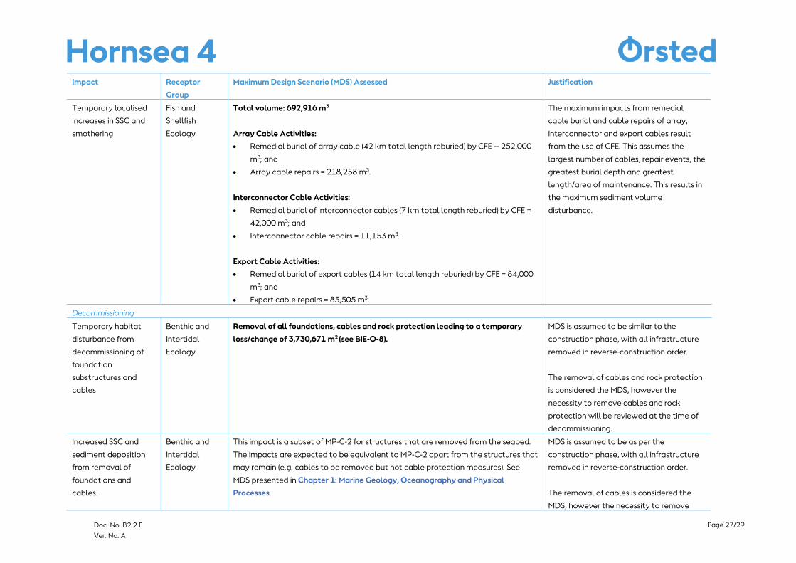
Temporary localised
increases in SSC and
smothering
Fish and
Shellfish
Ecology
Total volume: 692,916 m3
Array Cable Activities:
• Remedial burial of array cable (42 km total length reburied) by CFE – 252,000
m3; and
• Array cable repairs = 218,258 m3.
Interconnector Cable Activities:
• Remedial burial of interconnector cables (7 km total length reburied) by CFE =
42,000 m3; and
• Interconnector cable repairs = 11,153 m3.
Export Cable Activities:
• Remedial burial of export cables (14 km total length reburied) by CFE = 84,000
m3; and
• Export cable repairs = 85,505 m3.
The maximum impacts from remedial
cable burial and cable repairs of array,
interconnector and export cables result
from the use of CFE. This assumes the
largest number of cables, repair events, the
greatest burial depth and greatest
length/area of maintenance. This results in
the maximum sediment volume
disturbance.
Decommissioning
Temporary habitat
disturbance from
decommissioning of
foundation
substructures and
cables
Benthic and
Intertidal
Ecology
Removal of all foundations, cables and rock protection leading to a temporary
loss/change of 3,730,671 m2 (see BIE-O-8).
MDS is assumed to be similar to the
construction phase, with all infrastructure
removed in reverse-construction order.
The removal of cables and rock protection
is considered the MDS, however the
necessity to remove cables and rock
protection will be reviewed at the time of
decommissioning.
Increased SSC and
sediment deposition
from removal of
foundations and
cables.
Benthic and
Intertidal
Ecology
This impact is a subset of MP-C-2 for structures that are removed from the seabed.
The impacts are expected to be equivalent to MP-C-2 apart from the structures that
may remain (e.g. cables to be removed but not cable protection measures). See
MDS presented in Chapter 1: Marine Geology, Oceanography and Physical
Processes.
MDS is assumed to be as per the
construction phase, with all infrastructure
removed in reverse-construction order.
The removal of cables is considered the
MDS, however the necessity to remove
Page 28/29
Doc. No: B2.2.F
Ver. No. A
Impact Receptor
Group
Maximum Design Scenario (MDS) Assessed Justification
cables will be reviewed at the time of
decommissioning.
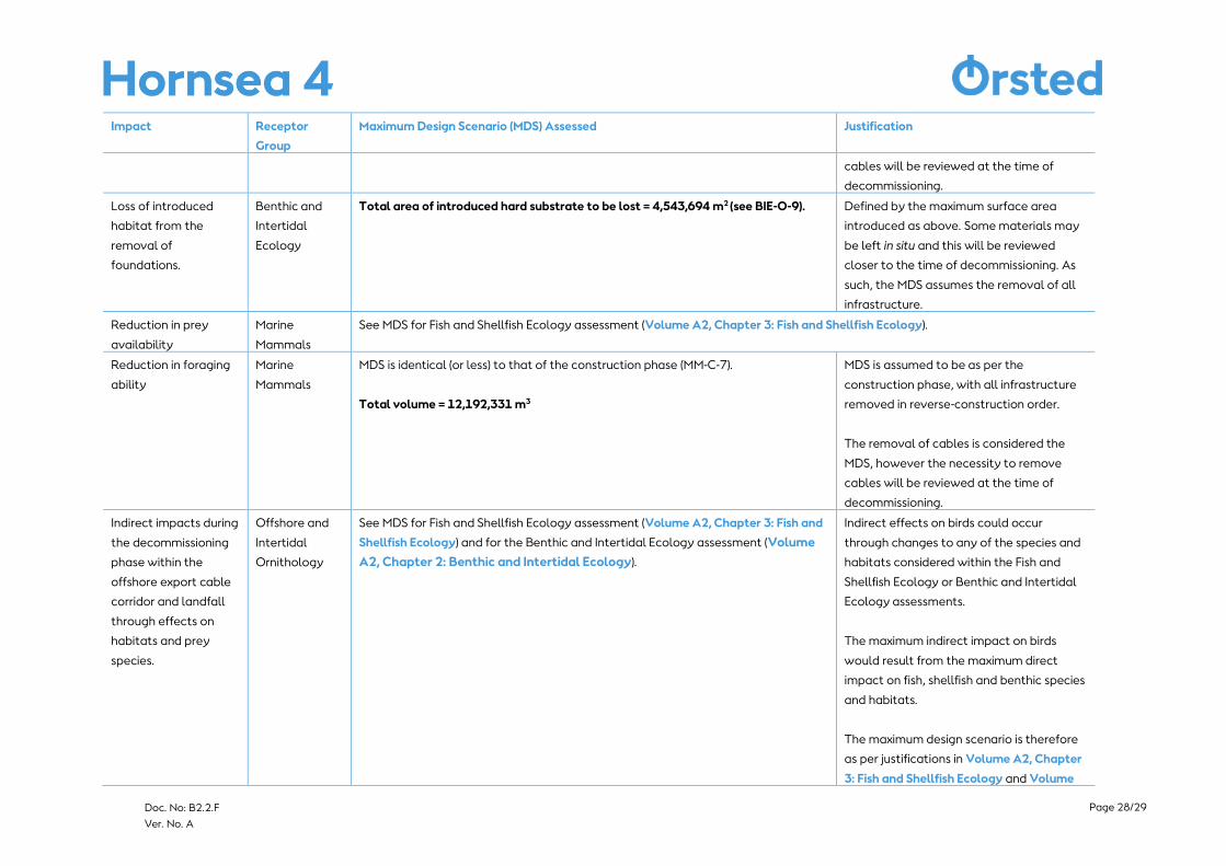
Loss of introduced
habitat from the
removal of
foundations.
Benthic and
Intertidal
Ecology
Total area of introduced hard substrate to be lost = 4,543,694 m2 (see BIE-O-9). Defined by the maximum surface area
introduced as above. Some materials may
be left in situ and this will be reviewed
closer to the time of decommissioning. As
such, the MDS assumes the removal of all
infrastructure.
Reduction in prey
availability
Marine
Mammals
See MDS for Fish and Shellfish Ecology assessment (Volume A2, Chapter 3: Fish and Shellfish Ecology).
Reduction in foraging
ability
Marine
Mammals
MDS is identical (or less) to that of the construction phase (MM-C-7).
Total volume = 12,192,331 m3
MDS is assumed to be as per the
construction phase, with all infrastructure
removed in reverse-construction order.
The removal of cables is considered the
MDS, however the necessity to remove
cables will be reviewed at the time of
decommissioning.
Indirect impacts during
the decommissioning
phase within the
offshore export cable
corridor and landfall
through effects on
habitats and prey
species.
Offshore and
Intertidal
Ornithology
See MDS for Fish and Shellfish Ecology assessment (Volume A2, Chapter 3: Fish and
Shellfish Ecology) and for the Benthic and Intertidal Ecology assessment (Volume
A2, Chapter 2: Benthic and Intertidal Ecology).
Indirect effects on birds could occur
through changes to any of the species and
habitats considered within the Fish and
Shellfish Ecology or Benthic and Intertidal
Ecology assessments.
The maximum indirect impact on birds
would result from the maximum direct
impact on fish, shellfish and benthic species
and habitats.
The maximum design scenario is therefore
as per justifications in Volume A2, Chapter
3: Fish and Shellfish Ecology and Volume
Page 29/29
Doc. No: B2.2.F
Ver. No. A
Impact Receptor
Group
Maximum Design Scenario (MDS) Assessed Justification
A2, Chapter 2: Benthic and Intertidal
Ecology.
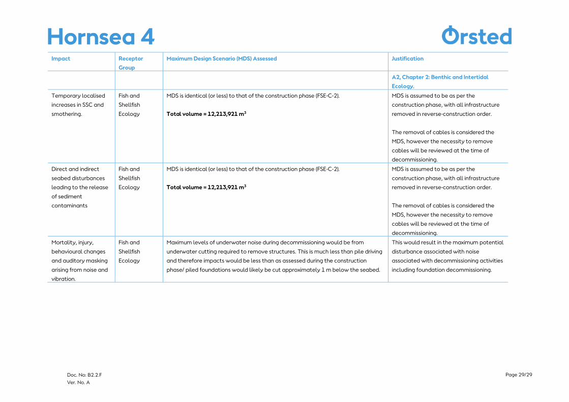
Temporary localised
increases in SSC and
smothering.
Fish and
Shellfish
Ecology
MDS is identical (or less) to that of the construction phase (FSE-C-2).
Total volume = 12,213,921 m3
MDS is assumed to be as per the
construction phase, with all infrastructure
removed in reverse-construction order.
The removal of cables is considered the
MDS, however the necessity to remove
cables will be reviewed at the time of
decommissioning.
Direct and indirect
seabed disturbances
leading to the release
of sediment
contaminants
Fish and
Shellfish
Ecology
MDS is identical (or less) to that of the construction phase (FSE-C-2).
Total volume = 12,213,921 m3
MDS is assumed to be as per the
construction phase, with all infrastructure
removed in reverse-construction order.
The removal of cables is considered the
MDS, however the necessity to remove
cables will be reviewed at the time of
decommissioning.
Mortality, injury,
behavioural changes
and auditory masking
arising from noise and
vibration.
Fish and
Shellfish
Ecology
Maximum levels of underwater noise during decommissioning would be from
underwater cutting required to remove structures. This is much less than pile driving
and therefore impacts would be less than as assessed during the construction
phase/ piled foundations would likely be cut approximately 1 m below the seabed.
This would result in the maximum potential
disturbance associated with noise
associated with decommissioning activities
including foundation decommissioning.
Top Related